
A-9155 - Audio Amplifier ONKYO - Free user manual and instructions
Find the device manual for free A-9155 ONKYO in PDF.
| Product Type | Integrated Amplifier |
| Brand | ONKYO |
| Model | A-9155 |
| Dimensions (W × H × D) | 435 × 121 × 344 mm |
| Weight | 6.8 kg |
| Power Supply | AC 230 V, 50 Hz |
| Power Consumption | 160 W |
| Standby Consumption | 0.2 W |
| Rated Output Power (IEC) | 2 × 65 W under 4 Ω, 1 kHz, 2 channels |
| Maximum Output Power (JEITA) | 2 × 80 W under 4 Ω, 1 kHz, 2 channels |
| Dynamic Power | 90 W + 90 W (4 Ω), 55 W + 55 W (8 Ω) |
| Total Harmonic Distortion | 0.08% (1 kHz, 1 W) |
| Damping Factor | 60 (1 kHz, 8 Ω) |
| Speaker Impedance | 4–16 Ω |
| Analog Audio Inputs | PHONO, CD, TUNER, TAPE, LINE/DOCK |
| Analog Audio Outputs | LINE/DOCK, TAPE |
| Speaker Outputs | 2 pairs (A, B) |
| Headphone Output | 1 (6.35 mm jack) |
| Frequency Response (CD) | 10 Hz – 100 kHz, +1 dB / –3 dB |
| Signal-to-Noise Ratio (CD, IHF-A) | 100 dB |
| Tone Controls | Bass: ±10 dB at 100 Hz, Treble: ±10 dB at 10 kHz, Loudness: +8 dB at 100 Hz, +4 dB at 10 kHz |
| Special Features | DIRECT mode, precision motorized volume control, discrete output circuit, audiophile capacitors |
| Care and Cleaning | Wipe with a dry or slightly damp cloth (mild soapy water). Do not use solvents. |
| Safety | Do not expose to water, do not open the casing, unplug during storms or prolonged disuse. |
| Spare Parts and Repairability | AC fuse not user accessible. Contact Onkyo after-sales service for any repairs. |
Frequently Asked Questions - A-9155 ONKYO
User questions about A-9155 ONKYO
0 question about this device. Answer the ones you know or ask your own.
Ask a new question about this device
Download the instructions for your Audio Amplifier in PDF format for free! Find your manual A-9155 - ONKYO and take your electronic device back in hand. On this page are published all the documents necessary for the use of your device. A-9155 by ONKYO.
USER MANUAL A-9155 ONKYO
Integrated Amplifier
A-9355/A-9155
Instruction Manual
Thank you for purchasing an Onkyo Integrated Amplifier. Please read this manual thoroughly before making connections and plugging in the unit.
Following the instructions in this manual will enable you to obtain optimum performance and listening enjoyment from your new Integrated Amplifier.
Please retain this manual for future reference.
Contents
Introduction 2
Connections 10
Enjoying Audio Sources. 14
Troubleshooting 17
Specifications 19
WARNING:
TO REDUCE THE RISK OF FIRE OR ELECTRIC SHOCK, DO NOT EXPOSE THIS APPARATUS TO RAIN OR MOISTURE.
CAUTION:
TO REDUCE THE RISK OF ELECTRIC SHOCK, DO NOT REMOVE COVER (OR BACK). NO USER-SERVICEABLE PARTS INSIDE. REFER SERVICING TO QUALIFIED SERVICE PERSONNEL.

WARNING
RISK OF ELECTRIC SHOCK
DO NOT OPEN
AVIS
RISQUE DE CHOC ELECTRIQUE
NE PAS OUVIR


The lightning flash with arrowhead symbol, within an equilateral triangle, is intended to alert the user to the presence of uninsulated "dangerous voltage" within the product's enclosure that may be of sufficient magnitude to constitute a risk of electric shock to persons.

The exclamation point within an equilateral triangle is intended to alert the user to the presence of important operating and maintenance (servicing) instructions in the literature accompanying the appliance.
Important Safety Instructions
-
Read these instructions.
-
Keep these instructions.
-
Heed all warnings.
-
Follow all instructions.
-
Do not use this apparatus near water.
-
Clean only with dry cloth.
-
Do not block any ventilation openings. Install in accordance with the manufacturer's instructions.
-
Do not install near any heat sources such as radiators, heat registers, stoves, or other apparatus (including amplifiers) that produce heat.
-
Do not defeat the safety purpose of the polarized or grounding-type plug. A polarized plug has two blades with one wider than the other. A grounding type plug has two blades and a third grounding prong. The wide blade or the third prong are provided for your safety. If the provided plug does not fit into your outlet, consult an electrician for replacement of the obsolete outlet.
-
Protect the power cord from being walked on or pinched particularly at plugs, convenience receptacles, and the point where they exit from the apparatus.
-
Only use attachments/accessories specified by the manufacturer.
-
Use only with the cart, stand, tripod, bracket, or table specified by the manufacturer, or sold with the apparatus. When a cart is used, use caution when moving the cart/apparatus combination to avoid injury from tip-over.
PORTABLE CART WARNING

S3125A
- Unplug this apparatus during lightning storms or when unused for long periods of time.
-
Refer all servicing to qualified service personnel. Servicing is required when the apparatus has been damaged in any way, such as power-supply cord or plug is damaged, liquid has been spilled or objects have fallen into the apparatus, the apparatus has been exposed to rain or moisture, does not operate normally, or has been dropped.
-
Damage Requiring Service
Unplug the apparatus from the wall outlet and refer servicing to qualified service personnel under the following conditions:
A. When the power-supply cord or plug is damaged,
B. If liquid has been spilled, or objects have fallen into the apparatus,
C. If the apparatus has been exposed to rain or water,
D. If the apparatus does not operate normally by following the operating instructions. Adjust only those controls that are covered by the operating instructions as an improper adjustment of other controls may result in damage and will often require extensive work by a qualified technician to restore the apparatus to its normal operation,
E. If the apparatus has been dropped or damaged in any way, and
F. When the apparatus exhibits a distinct change in performance this indicates a need for service.
- Object and Liquid Entry
Never push objects of any kind into the apparatus through openings as they may touch dangerous voltage points or short-out parts that could result in a fire or electric shock.
The apparatus shall not be exposed to dripping or splashing and no objects filled with liquids, such as vases shall be placed on the apparatus.
Don't put candles or other burning objects on top of this unit.
- Batteries
Always consider the environmental issues and follow local regulations when disposing of batteries.
- If you install the apparatus in a built-in installation, such as a bookcase or rack, ensure that there is adequate ventilation.
Leave 20cm (8") of free space at the top and sides and 10cm (4") at the rear. The rear edge of the shelf or board above the apparatus shall be set 10cm (4") away from the rear panel or wall, creating a flue-like gap for warm air to escape.
- Recording Copyright—Unless it's for personal use only, recording copyrighted material is illegal without the permission of the copyright holder.
- AC Fuse—The AC fuse inside the unit is not user-serviceable. If you cannot turn on the unit, contact your Onkyo dealer.
- Care—Occasionally you should dust the unit all over with a soft cloth. For stubborn stains, use a soft cloth dampened with a weak solution of mild detergent and water. Dry the unit immediately afterwards with a clean cloth. Don't use abrasive cloths, thinners, alcohol, or other chemical solvents, because they may damage the finish or remove the panel lettering.
4. Power Warning
BEFORE PLUGGING IN THE UNIT FOR THE FIRST TIME, READ THE FOLLOWING SECTION CAREFULLY.
AC outlet voltages vary from country to country. Make sure that the voltage in your area meets the voltage requirements printed on the unit's rear panel (e.g., AC 230 V, 50 Hz or AC 120 V, 60 Hz).
The power cord plug is used to disconnect this unit from the AC power source. Make sure that the plug is readily operable (easily accessible) at all times.
Some models have a voltage selector switch for compatibility with power systems around the world. Before you plug in such a model, make sure that the voltage selector is set to the correct voltage for your area.
Pressing the [STANDBY/ON] button on the remote controller to select Standby mode does not fully shutdown the unit. If you do not intend to use the unit for an extended period, remove the power cord from the AC outlet.
- Never Touch this Unit with Wet Hands—Never handle this unit or its power cord while your hands are wet or damp. If water or any other liquid gets inside this unit, have it checked by your Onkyo dealer.
6. Handling Notes
- If you need to transport this unit, use the original packaging to pack it how it was when you originally bought it.
- Do not leave rubber or plastic items on this unit for a long time, because they may leave marks on the case.
- This unit's top and rear panels may get warm after prolonged use. This is normal.
- If you do not use this unit for a long time, it may not work properly the next time you turn it on, so be sure to use it occasionally.
For British models
Replacement and mounting of an AC plug on the power supply cord of this unit should be performed only by qualified service personnel.
IMPORTANT
The wires in the mains lead are coloured in accordance with the following code:
Blue: Neutral
Brown: Live
As the colours of the wires in the mains lead of this apparatus may not correspond with the coloured markings identifying the terminals in your plug, proceed as follows:
The wire which is coloured blue must be connected to the terminal which is marked with the letter N or coloured black.
The wire which is coloured brown must be connected to the terminal which is marked with the letter L or coloured red.
IMPORTANT
The plug is fitted with an appropriate fuse. If the fuse needs to be replaced, the replacement fuse must approved by ASTA or BSI to BS1362 and have the same ampere rating as that indicated on the plug. Check for the ASTA mark or the BSI mark on the body of the fuse.
If the power cord's plug is not suitable for your socket outlets, cut it off and fit a suitable plug. Fit a suitable fuse in the plug.
For European Models
Declaration of Conformity
We, ONKYO EUROPE ELECTRONICS GmbH LIEGNITZERSTRASSE 6, 82194 GROEBENZELL, GERMANY

declare in own responsibility, that the ONKYO product described in this instruction manual is in compliance with the corresponding technical standards such as EN60065, EN55013, EN55020 and EN61000-3-2, -3-3.
GROEBENZELL, GERMANY

K. MIYAGI
ONKYO EUROPE ELECTRONICS GmbH
Introduction
Important Safety Instructions 2
Precautions 3
Table of Contents. 4
Features 4
Supplied Accessories. 5
Using the Remote Controller 5
Installing the Remote Controller's Batteries.....5
Front & Rear Panels.. 6
Front Panel 6
Rear Panel. 7
Remote Controller. 8
Remote Controller (Buttons to control the A-9355/A-9155) 8
Remote Controller (Buttons to control Onkyo products other than A-9355/A-9155)......8
Connections
Connecting the A-9355/A-9155 10
Connecting Your Speakers 10
Before Making any Connections 11
Audio Components. 11
Connecting a Turntable 11
Connecting a CD Player 11
Connecting a Tuner 12
Connecting a Cassette Deck 12
Connecting an MD Recorder 12
Connecting a Remote Interactive Dock (RI Dock) 12
Connecting a TV or Other Component with an Audio Output. 12
Connecting RI Components. 13
Connecting Another Component's Power Cord 13
Enjoying Audio Sources
Connecting the Power Cord. 14
Turning On the A-9355/A-9155. 14
Selecting Speaker Set A or B 14
Listening to Components 15
Muting the A-9355/A-9155 (remote controller only) 15
Using Headphones. 15
Using the Tone Controls. 16
Setting the PURE DIRECT Function (A- 9355) 16
Setting the DIRECT Function (A-9155) ...16
Adjusting the Bass 16
Adjusting the Treble 16
Loudness Control 16
Recording 16
Others
Troubleshooting. 17
Specifications. 19
Features
A-9355 Integrated Digital Amplifier
Exclusive Onkyo VL Digital 2-Channel Amplifier
70 W/Ch into 8 ohms (IEC)
85 W/Ch into 8 ohms (JEITA)
Massive Power Transformer
All Discrete Output Stage Circuitry
Low-impedance, Thick Bus Plate
Optimum Gain Volume Circuitry
Audiophile-Grade Capacitors
Precision Motor Volume Control
□ Tone Control (Bass/ Treble/ Loudness On/Off)
Pure Direct Mode
Discrete Phono Equalizer Circuitry
6 Audio Inputs and 2 Outputs
Speaker A/B Drive
Thick, Hi-Rigidity, Anti-Resonant Flat Chassis
Aluminum Front Panel and Volume Knob
Gold-Plated Headphone Jack
AC Outlet Installed
□ RI-Dock Compatible Remote Control
A-9155 Integrated Amplifier
65 W/Ch into 4 ohms (IEC)
All Discrete Output Stage Circuitry
Optimum Gain Volume Circuitry
Audiophile-Grade Capacitors
Precision Motor Volume Control
□ Tone Control (Bass/ Treble/ Loudness On/Off)
Direct Mode
Phono Equalizer Circuitry
5 Audio Inputs and 2 Outputs
Speaker A/B Drive
Hi-Rigidity, Anti-Resonant Chassis
Aluminum Front Panel and Volume Knob
Gold Plated Headphone Jack
AC Outlet Installed
RI-Dock Compatible Remote Control
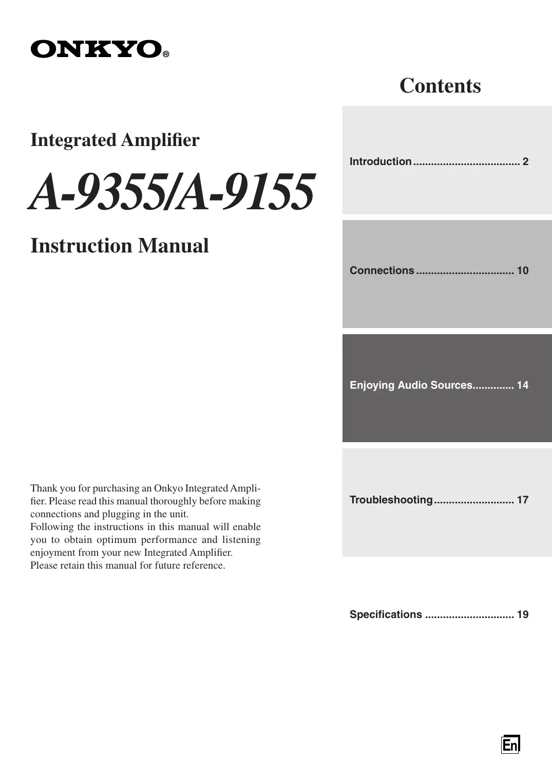
Make sure you have the following accessories:
Remote controller & two batteries (AA/R6)
In catalogs and on packaging, the letter added to the end of the product name indicates the color of the
A-9355/A-9155. Specifications and operation are the same regardless of color.
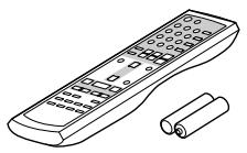
Using the Remote Controller
Point the remote controller toward the remote control sensor.
Notes:
- The remote controller may not work reliably if the A-9355/A-9155 is subjected to bright light, such as direct sunlight or inverter-type fluorescent lights. Keep this in mind when installing.
- If another remote controller of the same type is used in the same room, or the A-9355/A-9155 is installed close to equipment that uses infrared rays, the remote controller may not work reliably.
- Don't put anything, such as a book, on the remote controller, because the buttons may be pressed inadvertently, thereby draining the batteries.
- The remote controller may not work reliably if the A-9355/A-9155 is installed in a rack behind colored glass doors. Keep this in mind when installing.
- The remote controller will not work if there's an obstacle between it and the A-9355/A-9155's remote control sensor.
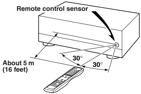
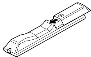
Installing the Remote Controller's Batteries
1 To open the battery compartment, press the small hollow and slide open the cover.
2 Insert the two supplied batteries (AA/R6) in accordance with the polarity diagram inside the battery compartment.
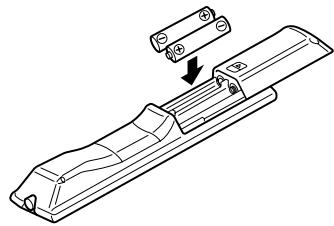
3 Slide the cover shut.
Notes:
- If the remote controller doesn't work reliably, try replacing the batteries.
- Don't mix new and old batteries or different types of batteries.
- If you intend not to use the remote controller for a long time, remove the batteries to prevent damage from leakage or corrosion.
- Flat batteries should be removed as soon as possible to prevent damage from leakage or corrosion.
Front Panel
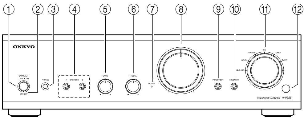
This illustration is for A-9355.
For detailed information, refer to the pages in parentheses.
① POWER switch (14)
This is the main power switch. When set to OFF, the A-9355/A-9155 is completely shutdown. When set to ON, the A-9355/A-9155 can be set to On or Standby.
② STANDBY indicator (14)
This indicator lights up when the A-9355/A-9155 is in Standby mode (Only the remote controller can be used to set the A-9355/A-9155 to Standby).
③ PHONES jack (15)
This phone jack is for connecting a standard pair of stereo headphones for private listening.
④ SPEAKERS A/B buttons and indicators (14)
These buttons are used to select which speaker set, A or B, outputs sound. The indicators show if each speaker set is on or off.
⑤ BASS control (16)
This control is for adjusting the level of bass sounds.
⑥ TREBLE control (16)
This control is for adjusting the level of treble sounds.
⑦ MUTING indicator (15)
The indicator lights up while muting function is activated.
Volume control (15)
This control is used to adjust the volume of the A-9355/A-9155.
(9) (A-9355) PURE DIRECT button and indicator (16)
This button turns the PURE DIRECT function on and off. The indicator lights up when the PURE DIRECT function is on.
(A-9155) DIRECT button and indicator (16)
This button turns the DIRECT function on and off. The indicator lights up when the DIRECT function is on.
10 LOUDNESS button and indicator (16)
This button is for reinforcing both treble and bass when the volume is turned down low. Pressing the button turns the LOUDNESS function on and off. The indicator lights up when the LOUDNESS function is on.
Input selector and indicators (15)
This control is used to select the input sources. These indicators show the currently selected input source.
Remote control sensor (5)
This sensor receives control signals from the remote controller.
Rear Panel
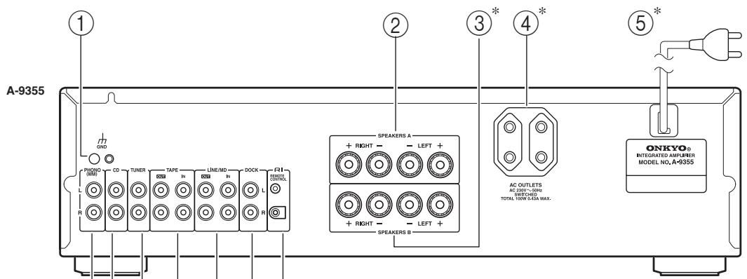
* Note that the number and geometry of each terminal may vary depending on product numbers and/or destined countries or lands.
The above illustration depicts a European model.
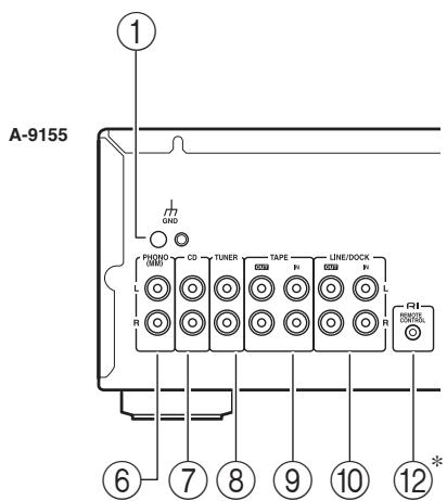
① Grounding terminal
This terminal is for connecting a turntable's ground wire.
② SPEAKERS A
These terminal posts are for connecting speaker set A.
③ SPEAKERS B
These terminal posts are for connecting speaker set B.
④ AC OUTLETS
These AC outlets can be used to supply power to another audio components. The type of outlets depend on the country in which you purchased the A-9355/A-9155.
⑤ Power Cord
After finished all the required connections, plug the power cord into a wall socket.
⑥ PHONO (MM) input
This analog audio input is for connecting a turntable with a moving-magnet cartridge.
⑦ CD input
This analog audio input is for connecting a CD player's analog audio output.
⑧ TUNER input
This analog audio input is for connecting a tuner's analog audio output.
⑨ TAPE IN/OUT
This analog audio input and output are for connecting a cassette deck with an analog audio output and input.
(10) (A-9355) LINE/MD IN/OUT (A-9155) LINE/DOCK IN/OUT
This analog audio input and output are for connecting a component's with an analog audio output and input. (MD recorder, TV, RI Dock, etc.)
1 DOCK IN (A-9355 only)
This analog audio input is for connecting a component's analog audio output (RI Dock, etc.).
⑫ R I REMOTE CONTROL jacks
The A-9355 has two jacks and the A-9155 has one. These RI (Remote Interactive) jacks can be connected to the RI jacks on your other Onkyo audio components. The A-9355/A-9155's remote controller can then be used to control all of your components. To use RI , you must make an analog audio connection between the A-9355/A-9155 and each component.
See pages 10-14 for connection information.
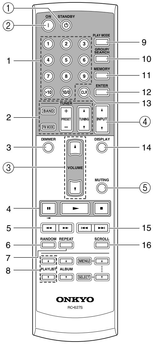
Remote Controller (Buttons to control the A-9355/A-9155)
This section describes the function of the buttons to control the A-9355/A-9155.
① STANDBY button (14)
This button is used to set the A-9355/A-9155 to Standby.
② ON button (14)
This button is used to turn on the A-9355/A-9155.
③ VOLUME [] / [] buttons (15)
These buttons adjust the volume of the A-9355/A-9155.
④ INPUT [▲]/[▼] buttons (15)
These buttons are used to select from the following input sources: LINE, HDD, PHONO, CD, TUNER, TAPE or MD.
⑤ MUTING button (15)
This button is used to mute the A-9355/A-9155.
Remote Controller (Buttons to control Onkyo products other than A-9355/A-9155)
When other Onkyo audio components are connected to the A-9355/A-9155 via RI, you can control them by using the corresponding buttons for each component listed in the following table.
Example: For 6 - Random button
- When the A-9355 has a MD player connected to the LINE/MD terminal, or a CD player to the CD terminal, the button functions as "RANDOM" control.
- When the A-9355 has a RI dock connected to the DOCK terminal, or the A-9155 has a RI dock connected to the LINE/DOCK terminal, the button functions as "SHUFFLE" control.
- The button functions as "DOLBY NR" control, when a cassette deck is connected to the TAPE terminal.
| Connecting Terminal | LINE/MD(A-9355) | DOCK(A-9355)LINE/DOCK(A-9155) | CD | TUNER | TAPE | |
| Component and(INPUT Name)Button on RemoteController | MDRecorder(MD) | RI Dock(DOCK) | CD Player(CD) | Tuner(TUNER) | Cassette Tape Deck(TAPE) | |
| 1 | 1 - 9 | 1 - 9 | 1 - 9 | |||
| 10/0 | 10/0 | 10//0 | ||||
| >10 | >10 | >10 | ||||
| 2 | BAND | BAND | ||||
| FM MODE | FM MODE | |||||
| PRESET +/- | PRESET +/- | |||||
| TUNING▲/▼ | TUNING▲/▼ | |||||
| 3 | DIMMER | DIMMER | ||||
| 4 | II | II | II | II | II* | |
| ▶ | ▶ | ▶ | ▶ | ▶* | ||
| ■ | ■ | ■ | ■ | ■* | ||
| 5 | ←/→ | ←/→ | ←/→ | ←/→ | ||
| 6 | RANDOM | RANDOM | SHUFFLE | RANDOM | DOLBY NR | |
| 7 | REPEAT | REPEAT | REPEAT | REPEAT | REV MODE | |
| 8 | PLAYLIST▲/▼ | PLAYLIST▲/▼ | ||||
| ALBUM▲/▼ | ALBUM▲/▼ | |||||
| MENU/SELECT/▲/▼ | MENU/SELECT/▲/▼ | |||||
| 9 | PLAY MODE | PLAY MODE | PLAY MODE | |||
| 10 | GROUP/SEARCH | GROUP | SEARCH(MP3 CD) | |||
| 11 | MEMORY | MEMORY | MEMORY | |||
| 12 | ENTER | ENTER | ENTER | |||
| 13 | CLR | CLR | CLR | |||
| 14 | DISPLAY | DISPLAY | BACKLIGHT | DISPLAY | ||
| 15 | ↓/→ | ↓/→ | ↓/→ | ↓/→ | ←/→ | |
| 16 | SCROLL | SCROLL | BACKLIGHT |
- Note also that some of the RI connected products may not be controlled with these buttons. For detailed information, refer to the relevant manuals provided for the individual products.
- For detailed information on the function of individual buttons, see Instruction Manual of the listed components.
- In the table above, blank cells indicate no function is available by pressing the button.
Connecting Your Speakers
Speaker Connection Precautions
You can connect one or two sets of speakers (A/B) to the A-9355/A-9155, and select which set outputs sound, or use both sets at the same time.
For both speakers A and B, make sure to connect them with Left and Right in pairs.
- If you connect both speaker sets to terminal A and B respectively to deliver sound at the same time, only connect speakers with an impedance of 8 ohms or more but less than 16 ohms. If you use speakers with a lower impedance, and use the A-9355/A-9155 at high volume levels for a long period of time, the built-in protection circuit may be activated.
- If you use speakers with an impedance of 4 to 8 ohms, connect them to either terminal A or B, or otherwise do not use both speaker sets simultaneously to deliver sound.
- Disconnect the power cord from the wall outlet before making any connections.
- Read the instructions supplied with your speakers.
- Pay close attention to speaker wiring polarity. In other words, connect positive (+) terminals only to positive (+) terminals, and negative (-) terminals only to negative (-) terminals. If you get them the wrong way around, the sound will be out of phase and will sound unnatural.
- Unnecessarily long or very thin speaker cables may affect the sound quality and should be avoided.
- Be careful not to short the positive and negative wires. Make sure also the wires do not touch the rear panel. Doing so may damage the A-9355/A-9155.
- Don't connect more than one cable to each speaker terminal. Doing so may damage the A-9355/A-9155.
- Don't connect a speaker to more than one pair of speaker terminals.
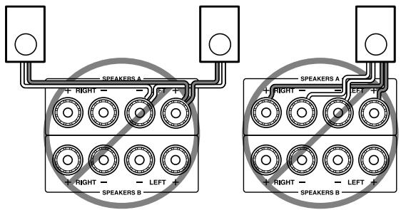
Connecting the Speaker Cables
1 Strip about 15mm (5/8 inch) of insulation from the ends of the speaker cables, and twist the bare wires tightly, as shown.

2 Unscrew the terminal.

3 Fully insert the bare wires.
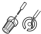
4 Screw the terminal tight.

The following illustration shows which speaker should be connected to each pair of terminals.
Before Making any Connections
- Always refer to the instructions that came with the component that you are connecting.
- Do not plug in the power cord until all connections have been properly made.
- Do not bind audio cables with power cords and speaker cables. Doing so may adversely affect the sound quality.
- To prevent interference, keep power cords and speaker cables away from the tuner's antenna.
RCA Audio Connection Color Coding
- Red connectors are used for the right channel, and white connectors are used for the left channel.
- Push each plug in all the way to make a good connection (loose connections can cause noise or malfunctions).

Audio Components
Connecting a Turntable
The A-9355/A-9155's PHONO input jacks are for use with moving-magnet (MM) type cartridges.
Use an analog audio cable to connect the
A-9355/A-9155's PHONO L/R jacks to the audio output jacks on the turntable, as shown.
If your amplifier has shorting pin plugs, remove the shorting pin plugs before connecting your turntable.
Notes:
- If the turntable has a ground wire, connect it to A-9355/A-9155's GND terminal. With some turntables, connecting the ground wire may cause hum, in which case it should be disconnected.
- If the turntable has a moving-coil (MC) type cartridge, you'll need a commercially available MC phono preamp. In this case, connect the turntable to the phono preamp's input, and connect the phono preamp's output to the A-9355/A-9155's PHONO L/R jacks.
Connecting a CD Player
Use an analog audio cable to connect the
A-9355/A-9155's CD L/R jacks to the analog audio output jacks on the CD player, as shown.
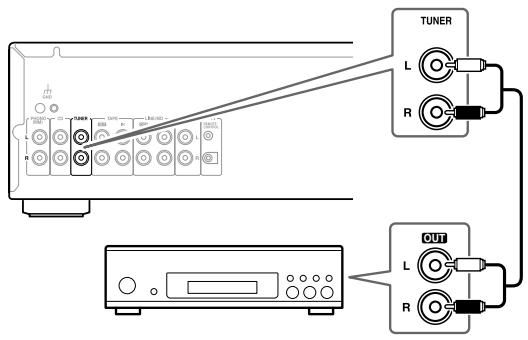
Connecting a Tuner
Use an analog audio cable to connect the A-9355/A-9155's TUNER L/R jacks to the analog audio output jacks on the tuner, as shown.
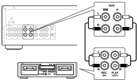
Connecting a Cassette Deck
Use an analog audio cable to connect the A-9355/A-9155's TAPE IN L/R jacks to the cassette deck's analog audio output jacks, and use another analog audio cable to connect the A-9355/A-9155's TAPE OUT L/R jacks to the cassette deck's analog audio input jacks, as shown.
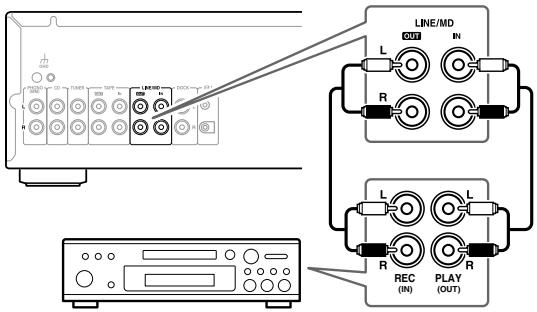
Connecting an MD Recorder
Use an analog audio cable to connect the A-9355/A-9155's MD IN L/R jacks to the MD recorder's analog audio output jacks, and use another analog audio cable to connect the A-9355/A-9155's MD OUT L/R jacks to the MD recorder's analog audio input jacks, as shown.
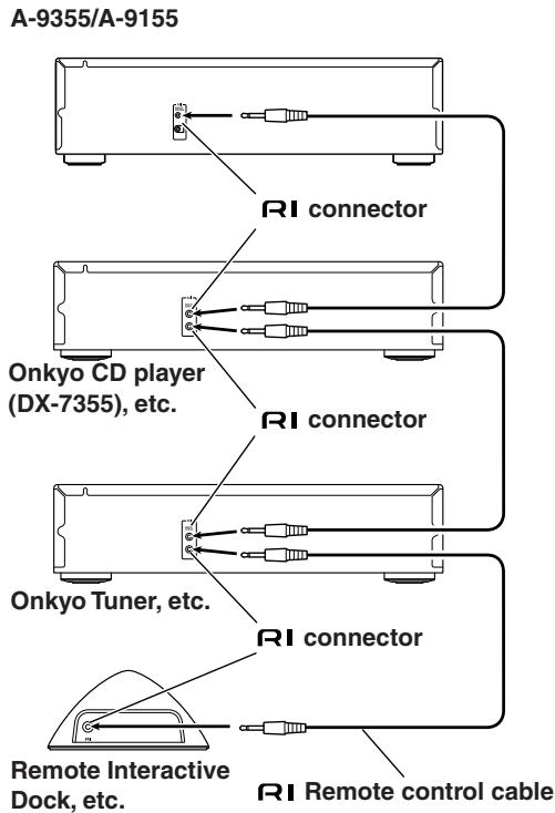
Connecting a Remote Interactive Dock (RI Dock)
Use an analog audio cable to connect the A-9355's DOCK Jack or A-9155's LINE/DOCK IN jack to the RI Dock's analog audio output jacks, and use an Rl cable to connect the A-9355/A-9155's Rl jack to the RI Dock's Rl jack, as shown.
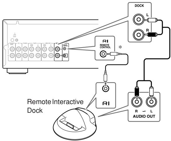
* See page 13 to connect multiple audio components using Rl jacks.
Note:
If you use the Onkyo Remote Interactive Dock (DS-A1), flip the RI MODE switch to "HDD" which is located on the underside.
Connecting a TV or Other Component with an Audio Output
Use an analog audio cable to connect the A-9355's LINE/MD IN jack or A-9155's LINE/DOCK IN jack to the analog audio output jacks on the TV or other component, as shown.
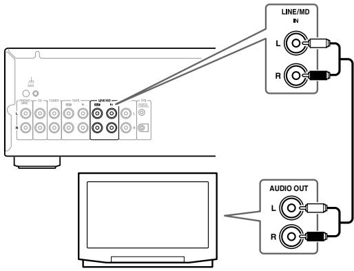
Note:
If your TV has no audio output, you can connect the A-9355/A-9155 to an audio output on your VCR and use its tuner.
Connecting R1 Components
With RI (Remote Interactive), you can control your RI-compatible Onkyo CD player, Tuner, and so on with the A-9355/A-9155's remote controller. If you connect other Onkyo components to the A-9355/A-9155 with the appropriate RI and audio cables, you can use the following system functions. RI cables are special cables solely for use with Onkyo products (no RI cables are supplied with the A-9355/A-9155).
When you set the A-9355/A-9155 to Standby, all connected components will go on Standby as well (the A-9355/A-9155's POWER switch must be set to ON for this to work).
Direct Change
When playback is started on an audio component connected via R1, the A-9355/A-9155 will automatically select that component as the input source.
Remote Control Operation
You can control all components in your system by using the A-9355/A-9155's remote controller. See page 8 and 9 for more information.
- To use R1, you must make an analog audio connection between the A-9355/A-9155 and each audio component.
Notes:
-
Push each plug in all the way to make a good connection.
-
A-9355: The A-9355 has two RI jacks. If you want to connect two or more audio components to the A-9355, it is advisable to connect any of two components directly to the A-9355 for better audio quality, in stead of linking all the components using the daisy chain method.
- Use only dedicated RI cables for RI connections (no RI cables are supplied with the A-9355/A-9155).
- The A-9355 has two RI jacks. They're all the same, so you can use either of them.
- R1 jacks should be connected only to Onkyo components. Connecting them to another manufacturer's component may cause the A-9355/A-9155 to malfunction.
- Some components may not support all R functions. See the manuals supplied with your other Onkyo components for more information.
Connecting Another Component's Power Cord
The A-9355/A-9155 has a switched AC OUTLETS on its rear panel. These can be used to connect the power cord of another audio component that you intend to use with the A-9355/A-9155.
After you power on the A-9355/A-9155, you can feed or shut off power to the connected component by turning on or off the remote controller switch. Use the AC outlet of the A-9355/A-9155 to feed only components that have no STANDBY/ON function, like Onkyo DX-7355 CD player. For Onkyo products equipped with RI terminals that have a STANDBY/ON function, allocate a normal outlet that is energized on a steady basis.
Note:
Do not connect any other devices than audio components.
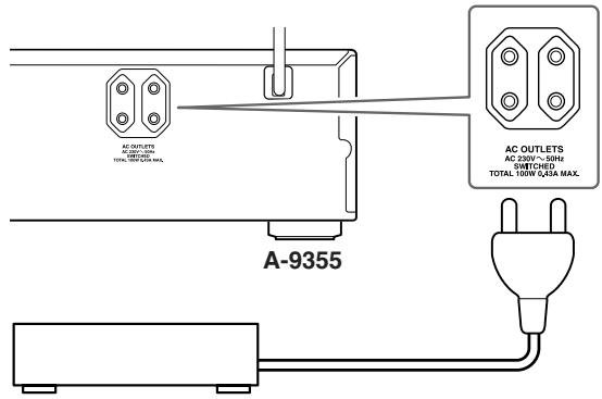
Caution:
Make sure that the maximum power requirement of the component connected to the AC OUTLETS do not exceed the capacity printed on the A-9355/A-9155's rear panel (100W).
Connecting the Power Cord
- Before connecting the power cord, connect all your speakers and audio components.
- Turning on the A-9355/A-9155 may cause a momentary power surge, which might interfere with other electrical equipment on the same circuit. If this is a problem, plug the A-9355/A-9155 into a different branch circuit.
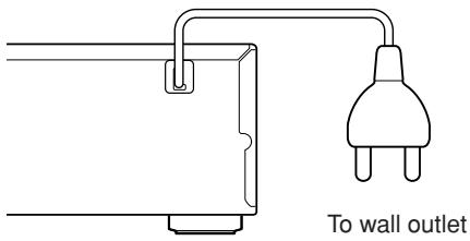
For home electric appliances which require a measureable amount of power, do not use the same wall outlet in which the A-9355/A-9155 is plugged so that the A-9355/A-9155 may operate under optimum conditions. Allocate them another wall outlet.
Turning On the A-9355/A-9155
1
A-9355/A-9155
Press the [POWER] switch.
The A-9355/A-9155 retains the power mode (on/standby) in which the amplifier was the last time you turned off the system.
Notes:
- The A-9355/A-9155 is shipped with the [POWER] switch in the OFF position (■). When the power cord is connected for the very first time or the [POWER] switch is set to ON (■) position, the A-9355/A-9155 will turn on.
- When it's turned on, the A-9355/A-9155 outputs no sound for about five seconds. This allows the circuits to stabilize.

2
Remote controller
STANDBY

To turn the A-9355/A-9155 on, press the [ON] button on the remote controller.
The STANDBY indicator goes off. To set the A-9355/A-9155 to Standby, press the [STANDBY] button on the remote controller.
The STANDBY indicator lights up.
Notes:
- To shut down the A-9355/A-9155 completely, set the [POWER] switch to the OFF position (■).
- For the sake of speaker protection, the A-9355/A-9155 waits for approximately 10 seconds after powered on before the system becomes stable to start delivering sound.
Powering on the whole system
This operation is available when you have Onkyo products with STANDBY/ON function connected through RI. Press first the ON button on the remote controller to turn the A-9355/A-9155 on. Press once again the ON button on the remote controller to power on every Onkyo component that is connected to the A-9355/A-9155 via RI.
Powering on the all the components at a time that are R I connected to the A- 9355/A- 9155
With the A-9355/A-9155 powered on, press and hold the ON button on the remote controller for more than 16 seconds. The system goes Standby. Now you can power on all the components connected to the A-9355/A-9155 at a time by pressing the ON button on the remote controller.
- To restore the setting, use the same procedure mentioned above.
Selecting Speaker Set A or B
SPEAKER selector
You can select which set of speakers outputs sound, or you can use both sets at the same time.
To output sound from the speakers connected to the SPEAKERS A terminals, press the SPEAKERS [A] button. The indicator above that button will light up. To output sound from the speakers connected to the SPEAKERS B terminals, press the SPEAKERS [B] button. The indicator above that button will light up. To output sound from all connected speakers, press the SPEAKERS [A] and SPEAKERS [B] button so that both indicators are on.
Listening to Components
1
A-9355/A-9155
Remote controller
Turn the input selector to select the component that you want to listen to.
LINE/MD (A-9355): Select to listen to the component connected to the LINE/MD jacks.
DOCK (A-9355): Select to listen to the component connected to the DOCK jacks.
LINE/DOCK (A-9155): Select to listen to the component connected to the LINE/DOCK jacks.
PHONO: Select to listen to the turntable connected to the PHONO jacks.
CD: Select to listen to the component connected to the CD jacks.
TUNER: Select to listen to the component connected to the TUNER jacks.
TAPE: Select to hear the component connected to the TAPE IN jacks.
When selecting with the remote controller, use the INPUT [Δ] / [] buttons.
2
Start playback on the selected component.
3
A-9355/ A-9155

Remote controller

VOLUME

To adjust the volume, use the A-9355/A-9155's Volume control, or the remote controller's VOL-UME [▲]/[▼] buttons.
Turn Volume control clockwise to increase the volume or counterclockwise to decrease the volume.
Muting the A-9355/A-9155 (remote controller only)
You can temporarily mute the output of the A-9355/A-9155.
1
MUTING

Press the remote controller's [MUTING] button.
The A-9355/A-9155 is muted. The MUTING indicator flashes.
MUTING

To unmute the A-9355/A-9155, press the [MUTING] button again. Note:
The Mute function will be cancelled if the remote controller's VOLUME buttons are pressed.
Using Headphones
You can connect a pair of stereo headphones (1/4-inch phone plug) to the A-9355/A-9155's PHONES jack for private listening.
Notes:
- Always turn down the volume before connecting your headphones.
(A-9355) All connected speakers are turned off while the headphones plug is inserted in the PHONES jack. - (A-9155) All connected speakers are not turned off even when the headphones plug is inserted in the PHONES jack. Press the SPEAKERS [A] or [B] button to mute the speakers.
Using the Tone Controls
Setting the PURE DIRECT Function (A-9355)
The [PURE DIRECT] button turns the PURE DIRECT function on and off.
When the PURE DIRECT function is off, the tone controls can be used to
adjust the sound, and the PURE DIRECT indicator goes off.
When the PURE DIRECT function is on, the tone controls are bypassed, so you can enjoy a pure sound. The PURE DIRECT indicator lights up.

PURE DIRECT
Setting the DIRECT Function (A-9155)
The [DIRECT] button turns the DIRECT function on and off.
When the DIRECT function is off, the tone controls can be used to adjust the sound, and the DIRECT indicator goes off.
When the DIRECT function is on, the tone controls are bypassed, so you can enjoy a pure sound. The DIRECT indicator lights up.

DIRECT
Adjusting the Bass
The BASS control adjusts bass sounds. Turn it up to make them louder. Turn it down to make them quieter.
Adjusting the Treble
The TREBLE control adjusts treble sounds. Turn it up to make them louder. Turn it down to make them quieter.
Loudness Control
By pressing the [LOUDNESS] button, both treble and bass are reinforced when the volume is turned down low. Use this button according to the music

LOUDNESS
source and according to the listening area. Its purpose is to enrich the natural sound effects of both the treble and bass.
The indicator lights up when the LOUDNESS function is on.
- When the PURE DIRECT (or DIRECT) function is on, turn the function off to use the LOUDNESS effect.
Recording
Unless you have the full consent of the copyright holder, copyright laws prohibit using your recordings for anything other than personal enjoyment!
1
Use the input selector to select the component that you want to record from.
2
Prepare the recorder:
- Set the recorder so that it's ready for recording.
- If necessary, adjust the recording level on the recorder.
- See the recorder's manual for more information.
3
Start playback on the component selected in step 1.
Note:
If you select another input source during recording, the newly selected input source will be recorded.
Notes:
- (A-9355) You can record on a recorder that's connected to the LINE/MD OUT or TAPE OUT L/R jacks.
- (A-9155) You can record on a recorder that's connected to the TAPE OUT L/R or LINE/DOCK OUT L/R jacks.
- The tone controls have no effect on the signal being recorded.
If you have any trouble using the A-9355/A-9155, look for a solution here. If you can't resolve the issue yourself, contact your Onkyo dealer.
Power
Can't turn on the A-9355/A-9155.
- Make sure that the power cord is properly plugged into the wall outlet.
- Unplug the power cord from the wall outlet, wait ten seconds or more, then plug it in again.
The STANDBY indicator is flashing.
- The amp protection circuit has been activated. Remove the power cord from the wall outlet immediately and contact your Onkyo dealer.
Turning on the system from Standby without using remote controller.
- Begin by turning the POWER switch off (■). Next, with the SPEAKERS A button pressed, turn the POWER switch on (■).
Audio
There's no sound or it's very quiet.
- Make sure that all audio plugs are pushed in all the way (page 11).
- Make sure that the inputs and outputs of all components are connected properly.
- Make sure that the polarity of the speaker cables is correct and that the bare wires are in contact with the metal part of each speaker terminal (page 10).
- Make sure that the correct input source is selected (page 15).
- If the MUTING indicator flashes, press the remote controller's [MUTING] button to unmute the A-9355/A-9155 (page 15).
- Make sure that none of the cables are bent, twisted, or damaged.
- To use a turntable with a moving-coil (MC) type cartridge, you need a commercially available MC phono preamp (page 11).
- Verify if the SPEAKERS selector is configured correctly. If "OFF" is selected, no sound will be output from any of the speakers (page 14).
Noise can be heard.
- Using cable ties to bundle audio cables with power cords, speaker cables, and so on may degrade the audio performance, so don't bundle them together.
- An audio cable may be picking up interference. Try repositioning your cables.
The tone controls have no effect.
- (A-9355) If the PURE DIRECT indicator lights up, the PURE DIRECT function is on and the tone controls have no effect. Press the [PURE DIRECT] button to turn the function off. The PURE DIRECT indicator will go off (page 16).
- (A-9155) If the DIRECT indicator lights up, the DIRECT function is on and the tone controls have no effect. Press the [DIRECT] button to turn the function off. The DIRECT indicator will go off (page 16).
Remote Controller
The remote controller doesn't work.
- Make sure that the batteries are installed with the correct polarity (page 5).
- Install new batteries. Don't mix different types of batteries or old and new batteries (page 5).
- Make sure that the remote controller is not too far away from the A-9355/A-9155 and that there's no obstruction between the remote controller and the A-9355/A-9155's remote control sensor (page 5).
- Make sure that the A-9355/A-9155 is not subjected to direct sunshine or inverter-type fluorescent lights. Relocate if necessary (page 5).
- If the A-9355/A-9155 is installed in a rack or cabinet with colored glass doors, the remote controller may not work reliably when the doors are closed (page 5).
Can't control other components?
- If it's an Onkyo component, make sure that the RI cable and analog audio cable are connected properly. Connecting only an RI cable won't work. (page 13)
The A-9355/A-9155 contains a microcomputer for signal processing and control functions. In very rare situations, severe interference, noise from an external source, or static electricity may cause it to lock up. In the unlikely event that this happens, unplug the power cord from the wall outlet, wait at least ten seconds, and then plug it back in again.
Onkyo is not responsible for damages (such as CD rental fees) due to unsuccessful recordings caused by the unit's malfunction. Before you record important data, make sure that the material will be recorded correctly.
How to reset:
Begin by turning the POWER switch off (■). Next, with the SPEAKERS A and B buttons pressed at the same time, turn the POWER switch on (■). The whole display lights up and then the A-9355/A-9155 is reset, with the system turned on.
| A-9355 Integrated Digital Amplifier | A-9155 Integrated Amplifier | |
| Rated Output Power European (IEC): Maximum Output Power (JEITA): Dynamic power: THD (total harmonic distortion): Damping factor: Input sensitivity and impedance: Output level and impedance: Phono overload: Frequency response: Tone control: SN ratio: Speaker impedance: | 2ch × 70 W at 4 Ω, 1kHz, 2ch driven 2ch × 85 W at 4 Ω, 1kHz, 2ch driven 75 W + 75 W (4 Ω) 38 W + 38 W (8 Ω) 0.08 % (1 kHz, 1 W) | 2ch × 65 W at 4 Ω, 1kHz, 2ch driven 2ch × 80 W at 4 Ω, 1kHz, 2ch driven 90 W + 90 W (4 Ω) 55 W + 55 W (8 Ω) 0.08 % (Power Rated) 0.08 % (1 kHz, 1 W) |
| 60 (1 kHz, 8 Ω) 200 mV, 50 kΩ (LINE) 2.5 mV, 50 kΩ (PHONO MM) 200 mV, 2.2 kΩ (REC OUT) 70 mV (MM, 1 kHz, 0.5 %) 10 Hz–60 kHz, +1 dB–3 dB (CD) +10 dB, -10 dB, 100 Hz (BASS) +10 dB, -10 dB, 10 kHz (TREBLE) +8 dB, 100 Hz (LOUDNESS) +4 dB, 10 kHz (LOUDNESS) 100 dB (CD, IHF-A) 70 dB (PHONO, IHF-A) | 60 (1 kHz, 8 Ω) 150 mV, 50 kΩ (LINE) 2.5 mV, 50 kΩ (PHONO MM) 150 mV, 2.2 kΩ (REC OUT) 64 mV (MM, 1 kHz, 0.5 %) 10 Hz–100 kHz, +1 dB–3 dB (CD) +10 dB, -10 dB, 100 Hz (BASS) +10 dB, -10 dB, 10 kHz (TREBLE) +8 dB, 100 Hz (LOUDNESS) +4 dB, 10 kHz (LOUDNESS) 100 dB (CD, IHF-A) 70 dB (PHONO, IHF-A) | |
| 4–16 Ω | 4–16 Ω | |
| Power supply: European: Asian: | AC 230 V, 50 Hz AC 120 V, 60 Hz AC 220-230 V, 50/60 Hz | AC 230 V, 50 Hz |
| Power consumption European: Stand-by power consumption: Dimensions (W × H × D): Weight: | 46 W 45 W (120 V) 51 W (220V) 0.2 W 435 × 124 × 344 mm 17-1/8" × 4-7/8" × 13-9/16" 7.3 kg (16.1 lbs) | 160 W 0.2 W 435 × 121 × 344 mm 17-1/8" × 4-3/4" × 13-9/16" 6.8 kg (15.0 lbs) |
| Analog inputs: Analog outputs: Speaker outputs: Phones: | PHONO, CD, TUNER, TAPE, LINE/MD, DOCK LINE/MD, TAPE 2 (A, B) 1 | PHONO, CD, TUNER, TAPE, LINE/DOCK LINE/DOCK, TAPE 2 (A, B) 1 |
Specifications and features are subject to change without notice.
ONKYO CORPORATION
Sales & Product Planning Div.: 2-1, Nisshin-cho, Neyagawa-shi, OSAKA 572-8540, JAPAN
Tel: 072-831-8023 Fax: 072-831-8124
18 Park Way, Upper Saddle River, N.J. 07458, U.S.A.
Tel: 201-785-2600 Fax: 201-785-2650 http://www.us.onkyo.com/
ONKYO EUROPE ELECTRONICS GmbH
Liegnitzerstrasse 6, 82194 Groebenzell, GERMANY
Tel: +49-8142-4401-0 Fax: +49-8142-4401-555 http://www.eu.onkyo.com/
ONKYO EUROPE UK Office
Suite 1, Gregories Court, Gregories Road, Beaconsfield, Buckinghamshire, HP9 1HQ
UNITED KINGDOM Tel: +44-(0)1494-681515 Fax: +44(0)-1494-680452
ONKYO CHINA LIMITED
Unit 1 & 12, 9/F, Ever Gain PlazaTower 1, 88, Container Port Road, Kwai Chung,
N.T., HONG KONG Tel: 852-2429-3118 Fax: 852-2428-9039
http://www.ch.onkyo.com/

D0702-1
- Integrated Amplifier
- A-9355/A-9155
- Instruction Manual
- Contents
- WARNING:
- CAUTION:
- WARNING
- AVIS
- Important Safety Instructions
- PORTABLE CART WARNING
- Power Warning
- Handling Notes
- For British models
- IMPORTANT
- For European Models
- Declaration of Conformity
- Introduction
- Connections
- Enjoying Audio Sources
- Others
- Features
- A-9155 Integrated Amplifier
- Using the Remote Controller
- Notes:
- Installing the Remote Controller's Batteries
- Front Panel
- Rear Panel
- ① Grounding terminal
- ② SPEAKERS A
- ③ SPEAKERS B
- ④ AC OUTLETS
- ⑤ Power Cord
- ⑥ PHONO (MM) input
- ⑦ CD input
- ⑧ TUNER input
- ⑨ TAPE IN/OUT
- (A-9355) LINE/MD IN/OUT (A-9155) LINE/DOCK IN/OUT
- DOCK IN (A-9355 only)
- ⑫ R I REMOTE CONTROL jacks
- Remote Controller (Buttons to control the A-9355/A-9155)
- Remote Controller (Buttons to control Onkyo products other than A-9355/A-9155)
- Example: For 6 - Random button
- Connecting Your Speakers
- Speaker Connection Precautions
- Connecting the Speaker Cables
- Before Making any Connections
- RCA Audio Connection Color Coding
- Audio Components
- Connecting a Turntable
- Connecting a CD Player
- Connecting a Tuner
- Connecting a Cassette Deck
- Connecting an MD Recorder
- Connecting a Remote Interactive Dock (RI Dock)
- Note:
- Connecting a TV or Other Component with an Audio Output
- Connecting R1 Components
- Direct Change
- Remote Control Operation
- Connecting Another Component's Power Cord
- Connecting the Power Cord
- Turning On the A-9355/A-9155
- Press the [POWER] switch.
- Powering on the whole system
- Powering on the all the components at a time that are R I connected to the A- 9355/A- 9155
- Selecting Speaker Set A or B
- Muting the A-9355/A-9155 (remote controller only)
- Using Headphones
- Using the Tone Controls
- Setting the PURE DIRECT Function (A-9355)
- Setting the DIRECT Function (A-9155)
- Adjusting the Bass
- Adjusting the Treble
- Loudness Control
- Recording
- Prepare the recorder:
- Power
- Can't turn on the A-9355/A-9155.
- The STANDBY indicator is flashing.
- Turning on the system from Standby without using remote controller.
- Audio
- There's no sound or it's very quiet.
- Noise can be heard.
- The tone controls have no effect.
- Remote Controller
- The remote controller doesn't work.
- Can't control other components?
- How to reset:
- ONKYO CORPORATION
Brand : ONKYO
Model : A-9155
Category : Audio Amplifier