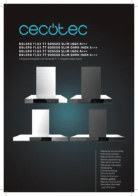
Bolero Flux Tt 609500 Slim A - Range hood CECOTEC - Free user manual and instructions
Find the device manual for free Bolero Flux Tt 609500 Slim A CECOTEC in PDF.


| Product Type | Wall-mounted range hood |
| Brand | Cecotec |
| Model | Bolero Flux Tt 609500 Slim A |
| Dimensions (W x D x H) | 60 x 30 x 10 cm |
| Net weight | 8 kg |
| Power supply | 220-240 V ~ 50 Hz |
| Motor power | 150 W |
| Lighting | LED 2 x 1.5 W |
| Speeds | 3 speeds + intensive speed |
| Max noise level | 65 dB(A) |
| Energy class | A |
| Max airflow | 650 m³/h |
| Control type | Touch |
| Grease filter | Metal filter, dishwasher safe |
| Charcoal filter | Optional, replace every 3 to 6 months |
| Special functions | Timer, filter saturation indicator |
| Exhaust mode | External exhaust or recirculation (with charcoal filter) |
| Material | Stainless steel and tempered glass |
| Cleaning and maintenance | Washable grease filters, clean surface with soft cloth and non-abrasive cleaner |
| Safety | Automatic shut-off after 10 hours of continuous operation |
| Spare parts available | Grease filters, charcoal filters, LED bulbs |
| Repairability | Repairability index of 7.5/10 |
Frequently Asked Questions - Bolero Flux Tt 609500 Slim A CECOTEC
User questions about Bolero Flux Tt 609500 Slim A CECOTEC
0 question about this device. Answer the ones you know or ask your own.
Ask a new question about this device
Download the instructions for your Range hood in PDF format for free! Find your manual Bolero Flux Tt 609500 Slim A - CECOTEC and take your electronic device back in hand. On this page are published all the documents necessary for the use of your device. Bolero Flux Tt 609500 Slim A by CECOTEC.
USER MANUAL Bolero Flux Tt 609500 Slim A CECOTEC
Safety instructions 9
-
Parts and components 71
-
Before use 71
-
Installation 72
-
Operation 75
-
Troubleshooting 77
-
Cleaning and maintenance 78
-
Recycling of electrical and electronic equipment 79
-
Copyright 79
-
Simplified EU Declaration of Conformity 80
SOMMAIRE
EN • The coding in this manual is generic and applies to all code variants of the appliance.
Read the following instructions carefully before using the appliance. Keep this instruction manual for future reference or new users.
- This appliance can be used by children aged 8 years and above and people with reduced physical, sensory or mental capabilities or lack of experience and knowledge if they have been given supervision or instruction concerning the use of the appliance in a safe way and understand the hazards involved. Children must not play with the appliance. Cleaning and user maintenance must not be carried out by children without supervision.
- This appliance is intended for domestic use only and is not suitable for use in commercial establishments such as bars, restaurants, farms, hotels, motels, and offices.
- If the power cord is damaged, it must be replaced by Cecotec's Official Technical Support Service or similar qualified personnel to avoid risks.
- Means for disconnection must be incorporated in the fixed wiring in accordance with the wiring rules.
- There must be adequate ventilation of the room when the kitchen hood is used at the same time as gas or other fuel burning appliances.
- There is a risk of fire if cleaning is not carried out according to the instructions.
- Do not flambé under the kitchen hood.
- CAUTION: Accessible parts can become hot when used with cooking appliances.
- Air must not be discharged into a duct that is used to exhaust fumes from appliances burning gas or other fuels.
- The minimum distance between the worktop and the lowest part of the kitchen hood, when it is located above
ENGLISH
a gas appliance, must be at least 65 cm. If the installation instructions for the gas appliance specify a greater distance, this must be taken into account. The distance of 65 cm can be reduced for:
III. Non-combustible parts of kitchen hoods.
IV. Parts operating at safety extra-low voltage (provided that these parts do not give access to live parts if they are deformed).
- The air discharge regulations must be complied with.
- The kitchen hood is intended for installation only over a hob with four cooking zones.
- Things you should never do:
IV. Do not attempt to use the kitchen hood without the mesh filter or if the filter is excessively dirty or greasy!
V. Do not install the kitchen hood above a cooker with a high level grill.
VI. Do not leave pans unattended during use because overheated fats or oils may catch fire.
- Accumulation of grease in the kitchen hood can cause a fire hazard. Clean the appliance according to the instructions in this manual.
- Exercise extreme caution when cleaning the appliance. Risk of burns and/or cuts. We recommend the use of gloves.
- Never leave open flames under the kitchen hood.
- If the kitchen hood is damaged, do not attempt to use it.
- When the kitchen hood and other non-electrically powered appliances are in simultaneous operation, the negative pressure in the room must not exceed 4 Pa (4 x 10⁻⁵ bar).
- Important! Always disconnect the power supply during installation and maintenance.
-
The kitchen hood must be installed in accordance with the installation instructions and in compliance with all measurements.
-
All installation work must be carried out by a qualified person or electrician.
- Dispose of the packaging material carefully. Children are vulnerable to it.
- Pay attention to sharp edges inside the kitchen hood, especially during installation and cleaning.
- Make sure that the duct does not have bends sharper than 90 degrees, as this will reduce the efficiency of the kitchen hood.
- Warning: Failure to install the screws or fastening device in accordance with these instructions may result in electrical hazards.
- Warning: Before accessing the electrical terminals, all power supply circuits must be disconnected.
- There must be adequate ventilation of the room when the kitchen hood is used at the same time as gas or other fuel burning appliances.
- Caution: The appliance and its accessible parts may become hot during operation. Be careful not to touch any accessible parts. Children under 8 years old must stay away, unless they are supervised.
- Local air discharge regulations must be complied with.
- For safety reasons, only use the supplied fixing or mounting screws (if applicable, depending on the model) or screws of the same size as those recommended in this instruction manual.
- Do not use a steam cleaner.
- NEVER attempt to extinguish a fire with water. Instead, switch off the appliance and then smother the flames using, for example, a lid or a fire blanket.
- Never use extension leads, multiple socket connections or external timer connection elements.
ENGLISH
- If the power cord is damaged, it must be replaced by the official Cecotec Technical Support Service or by similarly qualified technicians to prevent hazards.
- The appliance must not be operated if the power supply cord is damaged or cut.
- If the appliance stops working or malfunctions abnormally, disconnect it from the mains and contact the official Cecotec Technical Support Service.
- Cecotec disclaims all liability for any damage or injury caused as a result of failure to follow the installation and/or operating instructions contained in this instruction manual.
INSTRUCTIONS DE SÉCURITÉ
The graphics in this manual are schematic representations and may not exactly match the product.
2. BEFORE USE
- This appliance comes in a packaging designed to protect it during transport. Remove the appliance from its box. You can keep the original box and other packaging materials in a safe place to prevent damage to the appliance if you need to transport it in the future. If you wish to dispose of the original packaging, make sure all items are recycled properly.
- Check that all parts and components are included and in good condition. If any of them are missing or damaged, please contact Cecotec's Official Technical Support Service immediately.
Box content:
- Extractor hood
- Instruction manual
- 2 carbon filters (not installed)
- Instruction manual
- Do not remove the product's serial number in order to keep proper traceability if technical assistance is required.
ENGLISH
3. INSTALLATION
NOTE: To ensure optimal air extraction, it is essential to comply with the following guidelines: Failure to follow these instructions will reduce performance and increase the noise level of the kitchen hood.
- All installation work must be carried out only by a qualified electrician or competent person.
- Do not connect the hood's exhaust duct to an existing ventilation system used for another appliance, such as a chimney.
- Figure 2 shows the kitchen hood dimensions.
Ventilation methods
Fig. 3
A. Roof ventilation: The duct exits vertically through the roof.
B. Wall ventilation: The duct exits horizontally through an external wall.
C. Recirculation (without ventilation): Air is purified through carbon filters (included, not installed) and returned to the kitchen. A deflector is required to direct the air.
Fig. 3 key:
A. Roof ventilation
- Roof
- Ventilation duct
- Hood
B. Wall ventilation
- Ventilation duct
- Hood
- Cover
C. Recirculation
- Deflector
- Hood
Ventilation system requirements
- The exhaust outlet must lead to the exterior. It must not end up in a loft, attic or other enclosed space.
- Use only rigid metal ventilation ducts. Plastic or flexible aluminium ducts (foil-type) are not recommended.
-
The ventilation system must include a damper. If the wall or roof cap already has one, do not use the damper supplied with the hood.
-
To maximise ventilation performance:
- Minimise duct length and number of bends.
- Maintain constant duct diameter.
- Seal all connections with duct tape to prevent leaks.
- Seal the exterior wall or roof opening around the cap with mastic.
- The hood must be installed at a height of 650-750 mm above the hob.
Guidelines for optimal air extraction
- The extraction duct bend angle must not be less than 120^ , and the duct must maintain a horizontal or upward path from the exit point to the exterior wall.
- After installation, ensure the hood is horizontally level to prevent grease accumulation on one side.
- Ensure the selected extraction duct complies with relevant standards and is fire-resistant.
Hood installation
Included hardware
Fig. 4
A. Expansion plugs (∅ 8 mm) - 9 pcs.
B. Fixing screws (ST4.0 x 30 mm) - 9 pcs.
C. Short screws (ST4.0 x 8 mm) - 4 pcs.
Installation steps
- Secure mounting plate: Drill 3 holes in the wall, insert 3 expansion plugs and screw the mounting plate with 3 fixing screws (4x30 mm). Fig. 5 and 6
- Mount the hood: Hang the hood body on the mounting plate. Fig. 7
- Remove the grease filters and mark from the inside the position of the two additional security holes.
- Remove the hood, drill the two holes, insert the plugs and rehang the hood to secure it permanently with the two security screws.
Decorative chimney installation
- Slide the upper chimney section (inner) over the lower section (outer). Pay attention to the position of the ventilation slots, depending on extraction or recirculation use. Fig. 8
- Place the lower section on the hood. Fix the lower wall bracket to the wall using 2 plugs and 2 screws (4x30 mm). Fig. 9
- Extend the upper chimney section to the desired height. Mark and drill the holes for the upper wall bracket.
ENGLISH
- Fix the upper wall bracket to the wall using 2 plugs and 2 screws (4x30 mm).
- Secure the upper chimney section to the upper wall bracket with 2 short screws (4x8 mm). Fig. 10
The air outlet duct curve angle must not be less than 120^ . Align the duct horizontally.
Alternatively, the duct should rise from the starting point and be conducted to an exterior wall. Fig. 11
After installation, ensure the kitchen hood is horizontally positioned to prevent grease accumulation on one side.
Ensure the selected outlet duct for installation complies with relevant standards and is fire-resistant.
Fig. 8 key:
- Upper part of the chimney (interior)
- Wall bracket
- Lower part of the chimney (exterior)
Fig. 10 key:
- Wall plug
- Wall bracket
- Screw (4 mm x 8 mm)
- Screw (4 mm x 30 mm)
Extraction tube installation (extraction mode)
Fig. 12
Note: Remove the protective film from the chimney before installation.
- Non-return valve installation: Attach the valve to the hood's air outlet.
- Exhaust tube installation: Connect the extraction tube to the non-return valve.
Fig. 13 key:
- One-way valve
- Air outlet
- Exhaust tube
Activated carbon filter installation
Fig. 13
When used in recirculation mode, carbon filters must be used to remove unpleasant food odours from the air.
- Remove the grease filters before installing the carbon filters.
- Place the carbon filter on the fan housing shaft, aligning the filter holes with the shaft.
- Rotate the carbon filter clockwise until securely fixed. To remove, rotate anticlockwise.
- Reinstall the grease filters.
Note:
Ensure the filter is securely fastened to prevent it from becoming detached and causing a hazard.
Be aware that suction power will be reduced when carbon filters are used.
Light replacement
Fig. 14
Note:
- Light replacement must only be carried out by qualified personnel.
- Before starting, disconnect all electrical connections.
- Allow the light to cool before replacing it.
-
Gloves should be worn to prevent direct hand contact, as this can shorten the lighting lifespan.
-
Remove the grease filters to access the light holders.
- Locate the light holders. In some models, the holders are covered by a light panel that must be removed first.
- Remove the LED panel and bracket screws, disconnect the light wiring and carefully replace the light.
- Reassemble everything after replacing the lamp and ensure all screws are fixed in the same position.
- Always use the same type and amperage of light for replacement.
4. OPERATION
Power On/Off button
- From standby mode: A 0.5-second press activates the hood at low speed.
- During operation: A short press turns off the hood. The lighting remains on when pressing this icon to stop the fan.
- Long press (3 seconds): Deactivates all functions (motor and light) and the hood enters standby mode.
- LED indicator light: Red in standby mode and off during operation.
ENGLISH
Light On/Off button
Colour temperature adjustment:
- With the hood in standby mode, press and hold the button for 3 seconds to enter setting mode. The + and - button LEDs will flash.
- Use the + and - buttons to adjust the light temperature from 3200K (warm) to 6500K (cool).
Brightness adjustment:
- Within temperature adjustment mode, a short press on the light button changes brightness intensity in the following sequence: 100% -> 75% -> 50% -> 75% -> 100%.
- Exit setting mode: Press and hold the light button to save settings and exit. The default light temperature is 3200K.
Speed decrease button
Decreases motor speed.
Speed increase button
Increases motor speed.
Speed indicator light
The speed level is indicated by a colour code:
- Green: Low speed.
- Yellow: Medium speed.
- Blue: High speed.
- Slow flashing blue: Booster 1.
- Fast flashing blue: Booster 2.
Filter cleaning indicator light
The indicator light illuminates after 20 hours of cumulative use.
Press and hold this button for 3 seconds to turn off the indicator and reset the hour counter.
Automatic mode button (AUTO)
- With the hood in standby mode, press and hold this button for 1 second to activate AUTO mode. The button LED will display a slow flash.
- After 30 seconds of detection, a beep will confirm activation. The thermal sensor will automatically adjust motor speed according to detected heat.
-
If no heat is detected, the motor will turn off after 3 minutes.
-
If you activate the fan manually while AUTO mode is active, AUTO mode will be deactivated. When you switch off the fan, AUTO mode will be reactivated.
- To deactivate AUTO mode, press and hold this button.
Air Cleaning function button
- With the hood in standby mode, press and hold this button for 1 second to activate this function.
- The hood will operate at low speed for 5 minutes and turn off for 55 minutes. This cycle will repeat continuously.
- During the 5-minute operation, the button LED will flash green. During the 55-minute pause, the LED will remain solid green. If the Air Cleaning function is activated and the cooker hood is switched on manually, the function will stop automatically. However, when the hood is switched off, the function will resume automatically.
- To deactivate the function, press and hold the button for 1 second.
Hand movement control function
Increase speed: In standby mode, wave your hand from left to right over the control panel to turn on the hood and sequentially increase speed (Off -> Low -> Medium -> High -> Booster 1 -> Booster 2).
Turn off motor: During operation, wave your hand from right to left to turn off the motor. In standby mode, the Hand Movement Control function will be switched off. Press and hold the "+" touch icon for 3 seconds to activate the function and press again for 3 seconds to deactivate it.
5. TROUBLESHOOTING
| PROBLEM | POSSIBLE CAUSE | SOLUTION |
| The light turns on, but the motor does not work. | Ventilation is blocked. | Remove the obstruction. |
| The capacitor is faulty. | Replace the capacitor by contacting Cecotec's Official Technical Support Service. | |
| The motor is faulty. | Replace the motor by contacting Cecotec's Official Technical Support Service. |
ENGLISH
| The motor does not work and the light does not turn on. | The light is faulty. | Replace the LED light by contacting Cecotec's Official Technical Support Service. |
| The plug is loose. | Secure the plug in the power socket. | |
| The kitchen hood vibrates. | The fan wheel is damaged. | Replace the fan wheel by contacting Cecotec's Official Technical Support Service. |
| The motor is not properly secured. | Secure the motor. | |
| The hood is not properly fixed to the wall. | Secure the hood. | |
| Smoke is not properly extracted. | The distance between the hood and the hob is excessive. | Reduce the height of the hood. |
| Excess airflow. | Reduce airflow by closing windows or doors. |
6. CLEANING AND MAINTENANCE
Warning: Switch off and unplug the hood before carrying out any cleaning tasks.
External surfaces:
External surfaces are susceptible to scratches and stains. Use mild cleaning agents and immediately remove any residue of alkaline or acidic substances (such as lemon juice or vinegar).
Stainless steel surfaces:
Clean regularly with a specific stainless steel cleaner.
Always wipe in the direction of the grain to prevent surface scratches.
Control panel:
Clean with a damp cloth and mild detergent. Ensure the cloth is well wrung out.
Dry with a soft cloth to remove excess moisture.
Grease filters:
Clean filters monthly to prevent fire hazards.
Filters collect grease, smoke and dust, affecting hood efficiency.
Wash filters with warm water and neutral detergent. Allow to air dry before reinstalling.
Warning: Do not use wire wool or abrasive brushes, as they could permanently damage the filter surface.
7. RECYCLING OF ELECTRICAL AND ELECTRONIC EQUIPMENT
This symbol indicates that, according to the applicable regulations, the product and/or battery must be disposed of separately from household waste. When this product reaches the end of its shelf life, you should dispose of the batteries/accumulators and take them to a collection point designated by the local authorities.
For detailed information on how to properly dispose of electrical and
electronic equipment and/or the corresponding batteries, consumers should contact their local authorities.
Compliance with the above guidelines will help protecting the environment.
8. COPYRIGHT
The intellectual property rights over the texts in this manual belong to CECOTEC INNOVACIONES, S.L. All rights reserved. The content of this publication may not, either in part or in its entirety, be reproduced, stored in a retrieval system, transmitted or distributed by any means (electronic, mechanical, photocopying, recording or similar) without prior authorisation from CECOTEC INNOVACIONES, S.L.
ENGLISH
9. SIMPLIFIED EU DECLARATION OF CONFORMITY
CE Cecotec Innovaciones hereby declares that this appliance complies with the essential requirements and other relevant provisions of the regulations applicable in the European Union. This appliance has been designed, manufactured and tested in compliance with required safety and quality standards. The full text of the EU Declaration of Conformity can be found on the following website: https://cecotec.es/es/information/declaration-of-conformity
1. PIÈCES ET COMPOSANTS
Img. 1
B. Ventilation murale
- Cheville
- Support mural
- Vis (4 mm x 8 mm)
- Vis (4 mm x 30 mm)
ulaşabilirsiniz: https://cecotec.es/es/information/declaration-of-conformity
1. MEPH KAI E≡APTHMATA
Σχήμα 1
- loafag loafag loafag loafag loafag loafag loafag loafag loafag loafag loafag loafag loafag loafag loafag loafag loafag loafag loafag loafag loafag loafag loafag loafag loafag loafag loafag loafag loafag loafag loafag loafag loafag loafag la
1,0<- o<- o<- o<-
A

B

C
Fig./Img./Abb./Afb./Rys. 3

8 9pcs

ST4.0 x 30
9pcs

ST4.0 x 8
4pcs
Fig./Img./Abb./Afb./Rys. 4

Fig./Img./Abb./Afb./Rys. 5

Fig./Img./Abb./Afb./Rys. 6
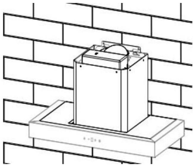
Fig./Img./Abb./Afb./Rys. 7


Fig./Img./Abb./Afb./Rys. 8

Fig./Img./Abb./Afb./Rys. 9
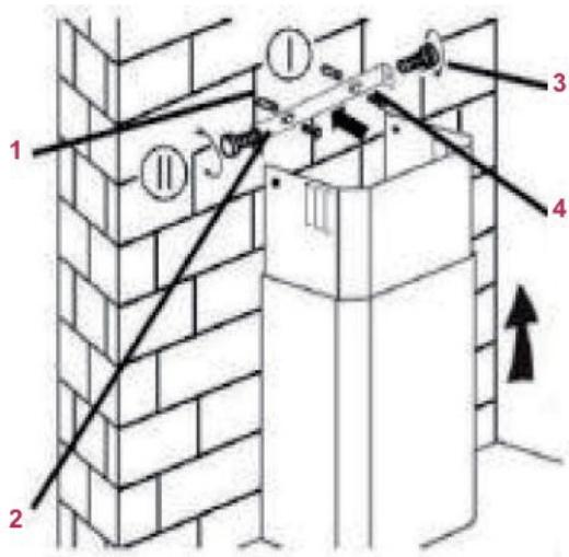
Fig./Img./Abb./Afb./Rys. 10

Fig./Img./Abb./Afb./Rys. 11

Fig./Img./Abb./Afb./Rys. 12
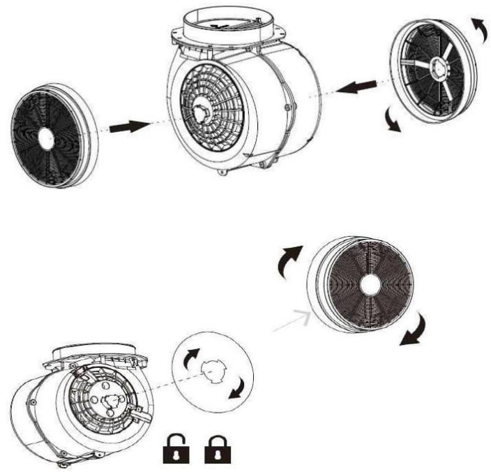
Fig./Img./Abb./Afb./Rys. 13
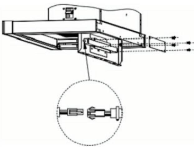
Fig./Img./Abb./Afb./Rys. 14
www.cecotec.es



- SOMMAIRE
- ENGLISH
- INSTRUCTIONS DE SÉCURITÉ
- BEFORE USE
- Box content:
- INSTALLATION
- Ventilation methods
- Fig. 3
- Fig. 3 key:
- Ventilation system requirements
- Guidelines for optimal air extraction
- Hood installation
- Installation steps
- Decorative chimney installation
- Activated carbon filter installation
- Light replacement
- OPERATION
- Power On/Off button
- Light On/Off button
- Brightness adjustment:
- Speed decrease button
- Speed increase button
- Speed indicator light
- Filter cleaning indicator light
- Automatic mode button (AUTO)
- Air Cleaning function button
- Hand movement control function
- TROUBLESHOOTING
- CLEANING AND MAINTENANCE
- External surfaces:
- Stainless steel surfaces:
- Control panel:
- Grease filters:
- RECYCLING OF ELECTRICAL AND ELECTRONIC EQUIPMENT
- COPYRIGHT
- SIMPLIFIED EU DECLARATION OF CONFORMITY
- PIÈCES ET COMPOSANTS
- Img. 1
- MEPH KAI E≡APTHMATA
- Σχήμα 1
Brand : CECOTEC
Model : Bolero Flux Tt 609500 Slim A
Category : Range hood