
AK-HC1500G - Surveillance Camera PANASONIC - Free user manual and instructions
Find the device manual for free AK-HC1500G PANASONIC in PDF.


| Product Type | Security Camera |
| Brand | Panasonic |
| Model | AK-HC1500G |
| Image Sensor | 2/3-type 2.2-Megapixel 3-MOS |
| Effective Pixels | 1920 x 1080 |
| Lens Mount | Bayonet |
| Video Outputs | HD-SDI, SD-SDI, Composite |
| Frame Rates | 1080/50i, 1080/59.94i, 720/50p, 720/59.94p |
| Minimum Illumination | 0.5 lux (F1.4, typical) |
| Power Consumption | 30 W |
| Power Supply | AC 100-240 V, 50/60 Hz |
| Dimensions (W x H x D) | 140 x 200 x 300 mm |
| Weight | Approx. 3.5 kg |
| Operating Temperature | 0°C to 40°C |
| Storage Temperature | -20°C to 60°C |
| Humidity Range | 30% to 90% (non-condensing) |
| Main Functions | Remote control, genlock, time code, focus assist, zebra pattern, electronic shutter |
| Maintenance | Clean lens with soft, dry cloth; check connections monthly; store in dry environment |
| Safety Precautions | Use only supplied power adapter; avoid rain or moisture; keep ventilation slots clear |
| Spare Parts Availability | Through Panasonic service centers; includes power supply, lens cap, mounting screws |
| Repairability | Modular design; service by qualified technicians; many parts replaceable on-site |
| General Information | Designed for indoor/outdoor use with appropriate housing; compatible with standard broadcast accessories |
Frequently Asked Questions - AK-HC1500G PANASONIC
User questions about AK-HC1500G PANASONIC
0 question about this device. Answer the ones you know or ask your own.
Ask a new question about this device
Download the instructions for your Surveillance Camera in PDF format for free! Find your manual AK-HC1500G - PANASONIC and take your electronic device back in hand. On this page are published all the documents necessary for the use of your device. AK-HC1500G by PANASONIC.
USER MANUAL AK-HC1500G PANASONIC
Operating Instructions
Multi Purpose Camera
AK-HC1500G

Panasonic®
Before attempting to connect, operate or adjust this product, please read these instructions completely.

CAUTION
RISK OF ELECTRIC SHOCK DO NOT OPEN

CAUTION: TO REDUCE THE RISK OF ELECTRIC SHOCK,
DO NOT REMOVE COVER (OR BACK).
NO USER SERVICEABLE PARTS INSIDE.
REFER TO SERVICING TO QUALIFIED SERVICE PERSONNEL.

The lightning flash with arrowhead symbol, within an equilateral triangle, is intended to alert the user to the presence of uninsulated “dangerous voltage” within the product’s enclosure that may be of sufficient magnitude to constitute a risk of electric shock to persons.

The exclamation point within an equilateral triangle is intended to alert the user to the presence of important operating and maintenance (service) instructions in the literature accompanying the appliance.
For CANADA
This equipment has been tested and found to comply with the limits for a class A digital device, pursuant to Part 15 of the FCC Rules. These limits are designed to provide reasonable protection against harmful interference when the equipment is operated in a commercial environment. This equipment generates, uses, and can radiate radio frequency energy, and if not installed and used in accordance with the instruction manual, may cause harmful interference to radio communications. Operation of this equipment in a residential area is likely to cause harmful interference in which case the user will be required to correct the interference at his own expense.
Warning:
To assure continued FCC emission limit compliance, the user must use only shielded interface cables when connecting to external units. Also, any unauthorized changes or modifications to this equipment could void the user's authority to operate it.

indicates safety information.
WARNING:
• TO REDUCE THE RISK OF FIRE OR ELECTRIC SHOCK, DO NOT EXPOSE THIS APPARATUS TO RAIN OR MOISTURE.
- THE APPARATUS SHALL NOT BE EXPOSED TO DRIPPING OR SPLASHING AND THAT NO OBJECTS FILLED WITH LIQUIDS, SUCH AS VASES, SHALL BE PLACED ON THE APPARATUS.
CAUTION:
TO REDUCE THE RISK OF FIRE OR SHOCK HAZARD AND ANNOYING INTERFERENCE, USE THE RECOMMENDED ACCESSORIES ONLY.
Note:
The rating plate is on the bottom of the unit.

indicates safety information.
IMPORTANT SAFETY INSTRUCTIONS
Read these operating instructions carefully before using the unit. Follow the safety instructions on the unit and the applicable safety instructions listed below. Keep these operating instructions handy for future reference.
1) Read these instructions.
2) Keep these instructions.
3) Heed all warnings.
4) Follow all instructions.
5) Do not use this apparatus near water.
6) Clean only with dry cloth.
7) Do not block any ventilation openings. Install in accordance with the manufacturer's instructions.
8) Do not install near any heat sources such as radiators, heat registers, stoves, or other apparatus (including amplifiers) that produce heat.
9) Do not defeat the safety purpose of the polarized or grounding-type plug. A polarized plug has two blades with one wider than the other. A grounding-type plug has two blades and a third grounding prong. The wide blade or the third prong are provided for your safety. If the provided plug does not fit into your outlet, consult an electrician for replacement of the obsolete outlet.
10) Protect the power cord form being walked on or pinched particularly at plugs, convenience receptacles, and the point where they exit from the apparatus.
11) Only use attachments/accessories specified by the manufacturer.
12) Use only with the cart, stand, tripod, bracket, or table specified by the manufacturer, or sold
with the apparatus. When a cart is used, use caution when moving the cart/apparatus combination to avoid injury from tip-over.
13) Unplug this apparatus during lightning storms or when unused for long periods of time.
14) Refer all servicing to qualified service personnel. Servicing is required when the apparatus has been damaged in any way, such as power-supply cord or plug is damaged, liquid has been spilled or objects have fallen into the apparatus, the apparatus has been exposed to rain or moisture, does not operate normally, or has been dropped.


indicates safety information.
Information on Disposal for Users of Waste Electrical & Electronic Equipment (private households)

This symbol on the products and/or accompanying documents means that used electrical and electronic products should not be mixed with general household waste.
For proper treatment, recovery and recycling, please take these products to designated collection points, where they will be accepted on a free of charge basis. Alternatively, in some countries you may be able to return your products to
your local retailer upon the purchase of an equivalent new product.
Disposing of this product correctly will help to save valuable resources and prevent any potential negative effects on human health and the environment which could otherwise arise from inappropriate waste handling.
Please contact your local authority for further details of your nearest designated collection point.
Penalties may be applicable for incorrect disposal of this waste, in accordance with national legislation.
For business users in the European Union
If you wish to discard electrical and electronic equipment, please contact your dealer or supplier for further information.
Information on Disposal in other Countries outside the European Union
This symbol is only valid in the European Union.
If you wish to discard this product, please contact your local authorities or dealer and ask for the correct method of disposal.
Contents
Accessories 5
Introduction 6
Characteristics 6
Precautions for use 7
Major operating controls and their functions 8
How to install 12
■How to set the lens 12
■How to install on the camera housing, pan/tilt head, tripod, etc. 12
How to set up the system 13
■Co nfiguration example 1: Connection of camera controller .... 13
■Co nfiguration example 2: High-speed P/T system ...... 14
Operation procedure 15
How to adjust 16
■FI ange back adjustment (for zoom lens) 16
■Lens iris gain volume adjustment .. 16
■White balance adjustment 17
■Co lor temperature and white balance adjustment (reference) ..... 17
■Black balance adjustment 18
■Gen-lock adjustment 18
Setting of menu items 19
■How to display the menus 19
■TOP menu 19
① MAINTENANCE menu 20
② SETTING menu 36
③ CAMERA ID menu 43
This camera employs new 2/3" 1 million-pixel IT CCD, realizing a compact light-weight system including the optical system.
The newly developed CCD image sensor, 14-bit A/D converter and brand-new DSP make for a wide dynamic range.
The self-contained format conversion circuit ensures support for a multiple number of HD formats including 1080/59.94i, 50i, 720/60p, 59.94p and 50p.
Making the best use of the features of a small-sized self-contain camera, it is accommodated in the camera housing and able to provide high-quality HD pictures as an multi purpose digital camera.
Characteristics
New 2/3" 1 million-pixel CCD is employed. [1280(H)×720(V)]
- 1 million-pixel CCD is 2/3'' in size, being compact and light-weight.
Multiple HD formats supported
- Signal output of many different formats enabled by incorporating a format conversion circuit in Panasonic's original LSI chip.
Fabrication of a circuit for 24 Hz-based formats also supported.
14-bit A/D conversion and brand-new DSP featured
- Wide dynamic range achieved
- Crystal-clear shooting even of images with different brightness levels
- Boosting of gain to a maximum 72 dB enabled
• Electronic extender function provided
• Cine gamma supported
Multiple functions
- Multi-function DTL such as high-luminance DTL and skin DTL.
- Right and left, top and bottom picture reversing function.
DON'TS DO'S
- Do not attempt to disassemble the camera or other units. In order to prevent electric shock, do not remove screws or covers. There are no user-serviceable parts inside.
- Do not abuse the camera. Avoid striking, shaking, etc. The camera contains sensitive components which could be damaged by improper handling or storage.
- Do not let the lens remain uncapped when the camera is not use. If the lens is not installed, do not leave the lens mount hole uncovered.
- Do not touch the surface of the lens or prism.
- Do not use strong of abrasive detergents when cleaning the camera body.
- Do not aim the camera toward the sun, no matter whether it is turned on or not.
- Do not expose the camera to rain or moisture, and do not try to operate the equipment in wet conditions. Do not operate the camera if it becomes wet.
- Do not operate the camera outdoors during a lightning storm.
- Do not use the camera in an extreme environment where high temperatures or high humidity exist.
- Do not leave the camera turned on when not in use. Do not unnecessarily turn the camera power on and off repeatedly. Do not block the ventilation slots.
-
Do not cover the port otherwise block ventilation during operation. Internal heat buildup can cause a fire.
-
Refer any servicing to qualified service personnel.
- Handle the camera with care.
- Protect the precision made lens by placing the lens cap over when the camera is not in use. If the lens is not installed, protect the surface of the prism by placing the body cap into the lens mount hole.
- Use a mild blower or lens cleaning tissue designed for coated lenses, to clean the surface of the lens or prism in the event that it should become dirty.
- Use a dry cloth to clean the camera if it is dirty. In case the dirt is hard to remove, use mild detergent and wipe gently.
- Use caution when operating the camera in the vicinity of spot lights or bright lights, as well as light reflecting objects and surfaces.
- Take immediate action if ever the camera should become wet. Turn the power off and have the unit checked by an authorized service facility.
- Follow normal safety precaution to avoid personal injury.
- Use the camera in an environment where the temperature is within 32° F - +104° F ( 0° C - +40° C), and the relative humidity is within 30% – 90% (no condensation).
- Always turn the power off when the camera is not going to be used. Operate the camera only when there is adequate ventilation.
There is internally provided a cooling fan. Since the cooling fan is a consumable part, replace it after about 30,000 hours of operation.
(Be sure to ask the dealer for the replacement.)
- Cooling fan
Major operating controls and their functions
■Front view ■Top view


■Bottom view ■Rear view

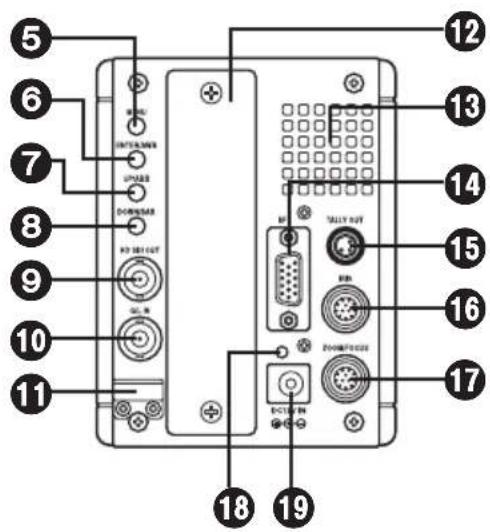
Major operating controls and their functions
① Lens mount
2/3" standard bayonet type (B4 mount) lens is installed.
② Lens fixing ring knob
Lens is fixed by turning the knob clockwise.
③ Camera mounting hole (1/4-20UNC)
④ Camera mounting hole (3/8-16UNC)
The screw holes can be used to secure the camera for installing it on camera housing, and when using a pan/tilt head or a tripod.
⑤ MENU switch [MENU]
A menu will appear on the monitor screen when MENU switch is pressed for at least 3 seconds. The menu screen is cleared when the switch is pressed for at least 3 seconds while the menu is displayed.
⑥ ENTER/AWB switch [ENTER/AWB]
The item just below can be selected by pressing this switch while the menu is on the screen.
When the menu is not displayed or the camera is in shooting mode, the automatic white balance control (AWB) can be set with this switch.
⑦ UP/ABB switch [UP/ABB]
The item just above can be selected by pressing this switch while the main menu is displayed.
While the Sub menu is displayed, any setting can be brought up to a higher value with this switch.
When the menu is not displayed or the camera is in shooting mode, the automatic black balance control (ABB) can be set with this switch.
⑧ DOWN/BAR switch [DOWN/BAR]
The item just below can be selected by pressing this switch while the Sub menu is on the screen.
While the Sub menu is displayed, any setting can be brought down to a lower value with this switch.
When the menu is not displayed, the color bar and the shooting conditions are alternately indicated by pressing the switch for about 5 seconds.
Each time the MENU switch ⑤ is pressed while the UP/ABB switch ⑦ and DOWN/BAR switch ⑧ is held down and while the menu is not displayed, the video output format is changed in the following sequence.
720/60p → 720/59.94p → 720/50p → 1080/60i → 1080/59.94i → 1080/50i →
1080/30p → 1080/29.97p → 1080/25p → 1080/24p → 1080/23.98p
When the video format is changed, the operate indicator 18 flashes twice with the 720/60p format and once with any other format.
Major operating controls and their functions
⑨ HD SDI output connector [HD SDI OUT]
SDI signal output is given by this line.
⑩ G/L input connector [G/L IN]
For gen-lock with the camera, the external sync signal (black burst) or tri-level sync signal is supplied to this input connector.
⑪ Cable clamp
Clamp the DC power supply cable connected to the DC 12 V input connector 19 to prevent it from slipping out.
⑫ Optional card slot
Slot for inserting an optional card. For details, refer to the manual for optional cards.
⑬ Cooling fan
- Do not block or obstruct the ventilation during operation. It may otherwise cause internal heating or fire.
- The life of this fan is approximately 50,000 hours (at room temp. 77°F (25°C) ). Replace the fan as needed.
(When the room temperature is higher than 95° F ( 35° C), replace the fan 30% earlier.)
Be sure to ask the dealer for the replacement.
⑭ Interface connector [I/F]
![PANASONIC AK-HC1500G - ⑭ Interface connector [I/F] - 1](/content/2026/07/1517866/images/a85af6d318381d85f72710be5d1bb9c1a1f4fc3b90ab319ffbae9a540b288c9c.jpg)
| Pin No. | Signal |
| 1 | Gen-lock signal GND |
| 2 | Time code signal input |
| 3 | Not used |
| 4 | TX_N (EIA422)/TXD (EIA232) output |
| 5 | RX_N (EIA422)/RXD (EIA232) output |
| 6 | Camera power supply input (DC +12 V) |
| 7 | Gen-lock signal input |
| 8 | GND |
| 9 | TX_P (EIA422) output |
| 10 | RX_P (EIA422) input |
| 11 | GND |
| 12 | Time code signal GND |
| 13 | GND |
| 14 | GND |
| 15 | GND |
Major operating controls and their functions
⑮ Tally output connector [TALLY OUT]
The R tally and G tally signals are output from this connector.
These signals take effect when the optional card for studio applications has been inserted.
| Pin No. Signal | |
| 1 GND | |
| 2 R_TALLY_OUT | |
| 3 G_TALLY_OUT | |
| 4 +12 V (500 mA Max) |
16 IRIS connector [IRIS]
Used to connect the IRIS control cables of the lens.

| Pin No. | Signal Pin No. Signal | ||
| 1 | Return control 7 Iris follow | ||
| 2 | VTR-S/S 8 Iris auto selection | ||
| 3 | UNREG GND 9 | — | |
| 4 | Iris manual selection | 10 | Zoom position information |
| 5 | Iris control | 11 | Focus position information |
| 6 | UNREG 12 V 12 | NC |
⑰ Zoom/Focus connector [ZOOM/FOCUS]
Used to connect the zoom/focus control cables of lens.

| Pin No. | Signal Pin No. | Signal | ||
| 1 | Focus control selection | 7 | COM | |
| 2 | Zoom control selection | 8 Focus control | ||
| 3 | GND | 9 Zoom control | ||
| 4 | Forcible iris closing | 10 | Iris control selection | |
| 5 | Iris control | 11 | COM +Voltage | |
| 6 +Voltage | 12 | COM -Voltage | ||
18 Operate indicator
Green LED lamp lights to indicate that the specified DC power is supplied to the DC 12 V input connector 19 .
When the video format is changed, the operate LED flashes twice when the format is 720/60p and once with any other format.
⑲ DC 12 V input connector [DC12V IN]
12 V DC is supplied through the optional DC power supply cable (AW-CA4T1).
![PANASONIC AK-HC1500G - ⑲ DC 12 V input connector [DC12V IN] - 1](/content/2026/07/1517866/images/b16aa5d2ad0711d881641eac19f0c9470d292cce7a2242a2f3ed567c71f5860f.jpg)
■How to set the lens
- Standard 2/3" bayonet type (B4 mount) lens of any makers can be used*.
① Turn the lens fixing ring knob counterclockwise to remove the lens mount cap.
② Set the lens in place, and turn the lens fixing ring knob clockwise to precisely fix the lens.
③ Connect the iris control cable to the IRIS connector.
④ Connect the zoom/focus control cable to the ZOOM/FOCUS connector.
* Note that there are some lenses uncontrollable with respect to zoom, focus function.

■How to install on the camera housing, pan/tilt head, tripod, etc.
① Precisely set the camera on the camera housing, pan/tilt head, tripod, etc. by using the camera set-screw hole (1/4-20UNC, 3/8-16UNC).
② When mounting the camera on a pan/tilt head, be sure to use proper tools and make sure that there is no fear of falling off.
■Configuration example 1: Connection of camera controller
- Use multi cable supplied with AK-HRP150G for the connection of camera controller AK-HRP150G and this unit.
![graph TD A["Lens"] --> B["Multi purpose camera AK-HC1500G"] B --> C["Panasonic"] C --> D["IRIS"] D --> E["HD SDI OUT"] E --> F["Monitor"] F --> G["Camera controller AK-HRP150G"] H["AC adapter AW-PS505A"] --> I["Panasonic"] I --> J["Panasonic"] J --> K["Monitor"]](/content/2026/07/1517866/images/f06a1093c278513820e1d96e821baf3642af95e79aaea4ecf55abca2c15e40c9.jpg)
① Before connecting the cables, be sure to set the power switch of AC adapter to OFF.
② Connect the multi cable to the interface connector of the camera, and the opposite side to camera controller.
③ Set the AC adapter power switch to ON, then the camera can be controlled.
④ After shooting, set the AC adapter power switch to OFF.
■Configuration example 2: High-Speed P/T system
![graph TD A["Lens"] --> B["HD SDI"] B --> C["Cable kit AW-CAK4HIG"] B --> D["Multi purpose camera AK-HC1500G"] B --> E["HD SDI"] E --> F["Cable kit AW-CAK4HIG (Camera control)"] E --> G["Monitor"] H["ZOOM/FOCUS"] --> I["10BASE-T straight cable (Pan/tilt control)"] I --> J["Pan/tilt control panel AW-R…](/content/2026/07/1517866/images/27076970828f33040c53aaa3d07f022aa109bfd9b7d43e36678f74577bcf226f.jpg)
1 Turn on the power of each equipment.
2 Properly adjust the light for the object.
3 Adjust the flange back of the lens, the iris and the focus.
- Flange back must be adjusted when the camera is used for the first time or after replacement of the lens.
4 Adjust the white balance.
- This adjustment is needed when the camera is used for the first time or after leaving unused for a long time.
- The adjustment is necessary when the lighting condition or brightness is changed.
- After adjusting the white balance once, re-adjustment is not needed under the same condition.
5 Adjust the black balance.
- This adjustment is needed when the camera is used for the first time or after leaving unused for a long time.
- The adjustment is necessary when the ambient temperature is greatly changed or at the change of season.
- After adjusting the black balance once, re-adjustment is not needed under the same condition.
6 Start shooting.
(After shooting, be sure to turn off the power of each equipment connected.)
■Flange back adjustment (for zoom lens)
The adjustment is to adjust the focus in all the range from the maximum zoom to the widest angle of the zoom lens.
① Shoot a dark object to open the iris.
② Adjust the distance from the object to 6.6 ft. (2 m) at least, then loosen the flange back fixing knob of the lens.
③ Set the lens to the maximum zoom and adjust the focus by turning the focus ring.
④ Set the lens to the widest angle and adjust the focus by turning the flange back adjust ring.
⑤ Repeat adjusting the focus ring and flange back adjust ring until the focus is adjusted within the zooming range.
⑥ After finishing the adjustment, tighten the flange back fixing knob.

Flange back adjust ring
■Lens iris gain volume adjustment
Iris gain adjust hole (G or S) is provided at front of the lens housing. Adjust the iris according to the following procedure by using a screwdriver.
① Set the iris select switch of the lens to A "AUTO" side.
② Turn the iris gain adjust volume to maximize the gain in such extent that no hunting takes place.
* When CAM is selected as the IRIS MODE setting on the camera menu, IRIS gain on the menu can be used to make adjustments.

■White balance adjustment
Adjust the white balance after shooting a white object by at least 50% of the screen.
NOTE: If the white signal level is over 100% or less than 50%, the white balance may not be normally adjusted.
■Color temperature and white balance adjustment (reference)
When carbon is burnt, it develops various colors of light depending on the temperature. Natural light can be specified by color temperature reflecting to the color developed when carbon is burnt.
The light of 3,200K (K=Kelvin, -273°C equals to absolute zero temperature 0K) represents the same value (color) as what develops when carbon is burnt at 3,200K (2,927°C).
The relationship between the color temperature of the light source and weather condition is indicated in the right figure. Let's study the difference of shooting an indoor object from shooting one outdoors. Studios are usually lighted with incandescent lamps and the color temperature of a white object in a studio is around 3,000K. The color temperature of a white object outdoors is around 6,500K. The former may look a little yellowish while the latter appears somewhat bluish when they are shot by a camera.
However, the human eye does not recognize color differences among these objects even under different ambient lighting conditions, because of their adaptability to light.

The video camera reproduces color differences with high fidelity and the color of an object somewhat different from what appears to the human eye.
Therefore, there is a need to adjust the white balance in order to correct differences between color temperatures.
NOTE
- Color temperature outdoors may vary depending on weather conditions.
■Black balance adjustment
- Adjust it with the lens closed.
When the motor drive lens is controlled from the camera, adjusting the black balance causes the lens to be automatically closed.
■Gen-lock adjustment
When multiple cameras are used or the camera is combined with other equipment, it is necessary to adjust the phase for phase matching by external synchronization.
• Horizontal phase adjustment
Observe the waveforms of externally synchronizing signal input (black burst signal) and video signal output by a two-phenomenon oscilloscope, and make the horizontal phase according to the camera menu.
Adjustment with GEN-LOCK of SETTING menu
When HD synchronizing signals are input:
① Roughly adjust the synchronizing signal input and video signal output phases by H PHASE-COARSE.
② Finely adjust the synchronizing signal input and video signal output phases by H PHASE-FINE.
| -** GEN-LOCK ** | |
| GEN-LOCK INPUT | :BNC |
| H PHASE-COARSE | :+00 |
| H PHASE-FINE | :+000 |
When SD synchronizing signals are input:
① Roughly adjust the synchronizing signal input and video signal output phases by SD-HD PHASE-COARSE.
② Finely adjust the synchronizing signal input and video signal output phases by SD-HD PHASE-FINE. If the adjustment performed using SD-HD PHASE is not satisfactory, use H PHASE-COARSE/FINE.
| -** GEN-LOCK ** | |
| GEN-LOCK INPUT | :BNC |
| H PHASE-COARSE | :+00 |
| H PHASE-FINE | :+000 |
| SD-HD PHASE CRS | :+0 |
| SD-HD PHASE FINE | :+00 |
■How to display the menus
Two methods are used to display the menus.
- Using AK-HC1500G multi purpose camera to display the menus:
① Hold down the MENU switch on the rear panel of the main unit for at least 3 seconds to display the TOP menu.
② Use the UP/DOWN switch to move the cursor to the target item, and press the ENTER switch to move to a menu at a lower hierarchical level.
• Using AK-HRP150G camera controller
① Press the MENU ON/OFF switch on the AK-HRP150G so that its lamp lights. The TOP menu now appears.
② Move the cursor to the target item, and press the MENU switch to move to a menu at a lower hierarchical level.
TOP menu
When the VIDEO MENU is selected: When the FILM MENU is selected:
-USER MENU
For automatically correcting the black shading.
CORRECT(DIG) [OFF, ON]
For ON/OFF control of the detection correction.
① MAINTENANCE menu
[2] PEDESTAL, GAMMA
| -** PEDESTAL, GAMMA (1/2) ** | |
| M PEDESTAL | :+000 |
| R PEDESTAL | :+000 |
| B PEDESTAL | :+000 |
| M GAMMA | :0.45 |
| R GAMMA | :+00 |
| B GAMMA | :+00 |
| M BLACK GAMMA | :+00 |
| R BLACK GAMMA | :+00 |
| B BLACK GAMMA | :+00 |
| GAMMA | :ON |
| BLACK GAMMA | :ON |
M PEDESTAL [-200 to +200]
For adjusting the black level.
R PEDESTAL [-100 to +100]
For correcting the red in relation to the master pedestal.
B PEDESTAL [-100 to +100]
For correcting the blue in relation to the master pedestal.
When the AK-HRP150G has been connected, M PEDESTAL, R PEDESTAL and B
PEDESTAL operations cannot be performed using the menu.
M GAMMA
[0.35 to 0.75 (DRS OFF), -10 to +10 (DRS ON)]
For adjusting the gamma characteristics.
R GAMMA
[-15 to +15 (DRS OFF), -10 to +10 (DRS ON)]
For adjusting the gamma characteristics of the red in relation to the master gamma characteristics.
B GAMMA
[-15 to +15 (DRS OFF), -10 to +10 (DRS ON)]
For adjusting the gamma characteristics of the blue in relation to the master gamma characteristics.
M BLACK GAMMA [-31 to +31]
For adjusting the gamma characteristics in the vicinity of the black.
R BLACK GAMMA [-15 to +15]
For adjusting the gamma characteristics of the red in the vicinity of the black in relation to the master gamma characteristics.
① MAINTENANCE menu
[2] PEDESTAL, GAMMA
-** PEDESTAL, GAMMA (1/2) **
M PEDESTAL : +000
R PEDESTAL : +000
B PEDESTAL : +000
M GAMMA : 0.45
R GAMMA : +00
B GAMMA : +00
M BLACK GAMMA : +00
R BLACK GAMMA : +00
B BLACK GAMMA : +00
GAMMA : ON
BLACK GAMMA : ON
When the VIDEO MENU is selected:
-** PEDESTAL, GAMMA (2/2) **
EFFECT DEPTH : 1
DRS : OFF
When the FILM MENU is selected:
-** PEDESTAL, GAMMA(2/2) **
CINE GAMMA SELECT: FILM REC
BLACK STR. LEVEL : 00%
DYNAMIC LEVEL : 500%
B BLACK GAMMA [-15 to +15]
For adjusting the gamma characteristics of the blue in the vicinity of the black in relation to the master gamma characteristics.
GAMMA [OFF, ON]
For turning the gamma correction ON or OFF.
BLACK GAMMA [OFF, ON]
For turning the black gamma correction ON or OFF.
When ON has been selected as the DRS setting, the BLACK GAMMA setting does not take effect.
EFFECT DEPTH [1 to 5]
For selecting the effects of the contrast adjustment when ON has been set for DRS.
DRS [OFF, ON]
For adjusting the contrast automatically when this is set to ON.
CINE GAMMA SELECT
[VIDEO REC, FILM REC]
For selecting either the film-use or video-use cine gamma characteristics.
BLACK STR. LEVEL [00% to 30%]
For setting the BLACK STRETCH position.
DYNAMIC LEVEL [200% to 500%]
For setting the dynamic range.
① MAINTENANCE menu
[3] FLARE
| -** FLARE ** | |
| R FLARE | :000 |
| G FLARE | :000 |
| B FLARE | :000 |
| FLARE | :ON |
R FLARE [000 to 100]
G FLARE [000 to 100]
B FLARE [000 to 100]
For adjusting the flare correction.
FLARE [OFF, ON]
For turning the flare correction ON or OFF.
① MAINTENANCE menu
[4] KNEE, WHITE CLIP
| -** KNEE,WHITE CLIP(1/2) ** | |
| M KNEE POINT | :95.00% |
| R KNEE POINT | :+00.00% |
| B KNEE POINT | :+00.00% |
| M KNEE SLOPE | :50 |
| R KNEE SLOPE | :+00 |
| B KNEE SLOPE | :+00 |
| A.KNEE POINT | :95.00% |
| A.KNEE LEVEL | :108% |
| M WHITE CLIP LVL | :109% |
| R WHITE CLIP LVL | :+00% |
| B WHITE CLIP LVL | :+00% |
M KNEE POINT
[80.00% to 107.00% (VIDEO MENU)]
[30% to 90% (FILM MENU/VIDEO REC)]
For adjusting the knee point.
R KNEE POINT [-25.00% to +25.00%]
For correcting the knee point of the red in relation to the master knee point.
B KNEE POINT [-25.00% to +25.00%]
For correcting the knee point of the blue in relation to the master knee point.
M KNEE SLOPE
[00 to 99 (VIDEO MENU)]
[150% to 600% (FILM MENU)]
For adjusting the knee slope.
R KNEE SLOPE [-99 to +99]
For adjusting the knee slope of the red in relation to the master knee slope.
B KNEE SLOPE [-99 to +99]
For adjusting the knee slope of the blue in relation to the master knee slope.
The M KNEE POINT and M KNEE SLOPE settings do not take effect when a setting other than MANUAL is selected for KNEE or ON is selected as the DRS setting when the VIDEO MENU has been selected or when FILM REC is selected as the CINE GAMMA SEL setting when the FILM MENU has been selected.
Similarly, the R/B KNEE POINT and R/B KNEE SLOPE settings do not take effect when a setting other than MANUAL is selected for KNEE or ON is selected as the DRS setting when the VIDEO MENU has been selected or when the FILM MENU has been selected.
① MAINTENANCE menu
[4] KNEE, WHITE CLIP
| -** KNEE,WHITE CLIP(1/2) ** | |
| M KNEE POINT | :95.00% |
| R KNEE POINT | :+00.00% |
| B KNEE POINT | :+00.00% |
| M KNEE SLOPE | :50 |
| R KNEE SLOPE | :+00 |
| B KNEE SLOPE | :+00 |
| A.KNEE POINT | :95.00% |
| A.KNEE LEVEL | :108% |
| M WHITE CLIP LVL | :109% |
| R WHITE CLIP LVL | :+00% |
| B WHITE CLIP LVL | :+00% |
A. KNEE POINT [80.00% to 107.00%]
For setting the auto knee break point position. This setting does not take effect when a setting other than AUTO is selected for KNEE or ON is selected as the DRS setting when the VIDEO MENU has been selected or when the FILM MENU has been selected.
A. KNEE LEVEL [100% to 109%]
For setting the maximum level of auto knee. This setting does not take effect when a setting other than AUTO is selected for KNEE or ON is selected as the DRS setting when the VIDEO MENU has been selected or when the FILM MENU has been selected.
M WHITE CLIP LVL [90% to 109%]
For setting the white clip level.
R WHITE CLIP LVL [-15% to +15%]
For correcting the amount of red for the M WHITE CLIP LVL.
B WHITE CLIP LVL [-15% to +15%]
For correcting the amount of blue for the M WHITE CLIP LVL.
① MAINTENANCE menu
[4] KNEE, WHITE CLIP
-** KNEE,WHITE CLIP(2/2)**
KNEE :MANUAL
WHITE CLIP :ON
HIGH COLOR :OFF
KNEE [OFF, MANUAL, AUTO]
For selecting the knee operation mode. This setting does not take effect when FILM REC is selected.
WHITE CLIP [OFF, ON]
For tuning white clip ON or OFF.
HIGH COLOR [OFF, ON]
For improving the color reproducibility of the high-brightness areas when it is set to ON. This setting does not take effect when a setting other than MANUAL is selected for KNEE or ON is selected as the DRS setting when the VIDEO MENU has been selected or when the FILM MENU has been selected.
[5] R/B GAIN
-** R/B GAIN **
R GAIN :+000
B GAIN :+000
ND FILTER :CLEAR
R GAIN [-200 to +200]
For adjusting the gain of the red.
B GAIN [-200 to +200]
For adjusting the gain of the blue.
ND FILTER [CLEAR, 1/4, 1/16, 1/64]
For selecting the ND filter setting.
When the AK-HRP150G has been connected, the items on this page cannot be operated using the menu.
① MAINTENANCE menu
[6] DETAIL
-** DETAIL(1/2) **
DETAIL :ON
TOTAL DTL LEVEL :+00
H DTL LEVEL :11
CRISP :02
LEVEL DEPENDENT :2
PEAK FREQUENCY :10
KNEE APERTURE :ON
KNEE APE LEVEL :3
DETAIL [OFF, ON]
For turning all the detail functions ON or OFF.
TOTAL DTL LEVEL [-31 to +31]
For setting the H DTL and V DTL levels.
H DTL LEVEL [0 to 63]
For setting the H DTL level.
CRISP [0 to 31]
For setting the noise elimination level of the detail signals.
LEVEL DEPENDENT [0 to 15]
For removing the detail in the dark areas.
PEAK FREQUENCY [00 to 31]
For setting the H DTL peak frequency.
KNEE APERTURE [OFF, ON]
For turning the emphasizing of the outlines for the high-brightness areas ON or OFF.
KNEE APE LEVEL [0 to 5]
For adjusting the knee aperture level.
① MAINTENANCE menu
[6] DETAIL
-** DETAIL(2/2) **
SLIM DETAIL :OFF
DETAIL(+) :+00
DETAIL(-) :+00
DETAIL CLIP :00
DETAIL SOURCE :(G+R)/2
SLIM DETAIL [OFF, ON]
For setting the detail more finely at ON.
DETAIL(+) [-31 to +31]
For adjusting the detail gain in the + direction.
DETAIL(-)[-31 to +31]
For adjusting the detail gain in the - direction.
DETAIL CLIP [0 to +63]
For minimizing the glare caused by adding too much detail as a result of a detail clip adjustment.
DETAIL SOURCE
[(G+R)/2, (G+B)/2, (2G+B+R)/4, (3G+B)/4, R, G]
For setting the ratio of the RGB signal components which create the detail.
① MAINTENANCE menu
[7] SKIN TONE DETAIL
| -** SKIN TONE DETAIL ** | |
| SKIN TONE DTL | :OFF |
| SKIN GET | :OFF |
| SKIN DTL CORING | :5 |
| Y MAX | :190 |
| Y MIN | :010 |
| I CENTER | :055 |
| I WIDTH | :090 |
| Q WIDTH | :010 |
| Q PHASE | :+000 |
SKIN TONE DTL [OFF, ON]
For turning the SKIN TONE DTL ON or OFF.
SKIN GET [OFF, ON]
When ON is selected, the box cursor is output to the screen center. When the image of the subject's skin is placed inside the box cursor and the ENTER operation is performed, I CENTER and Q PHASE are set automatically.
SKIN DTL CORING [0 to 7]
For setting the SKIN TONE DTL coring amount.
Y MAX [0 to 255]
For setting the upper limit of the brightness in the skin tone specification area.
Y MIN [0 to 255]
For setting the lower limit of the brightness in the skin tone specification area.
I CENTER [0 to 255]
For setting the phase of the I axis in the skin tone specification area.
I WIDTH [0 to 255]
For setting the phase width of the I axis in the skin tone specification area.
Q WIDTH [0 to 255]
For setting the phase range of the Q axis in the skin tone specification area.
Q PHASE [-128 to +127]
For setting the phase of the Q axis in the skin tone specification area.
① MAINTENANCE menu
[8] GAIN, AUTO IRIS
| -** GAIN,AUTO IRIS ** | |
| LOW GAIN | :0dB |
| MID GAIN | :9dB |
| HIGH GAIN | :18dB |
| A.IRIS LEVEL | :050 |
| A.IRIS PEAK/AVE | :050 |
| A.IRIS WINDOW | :NORM1 |
| IRIS MODE | :LENS |
| IRIS GAIN | :05 |
LOW GAIN [-6 dB to 30 dB]
MID GAIN [-6 dB to 30 dB]
HIGH GAIN [-6 dB to 30 dB]
For setting the amount by which the gain is to be increased when LOW, MID or HIGH has been selected by GAIN SELECT.
A. IRIS LEVEL [0 to 100]
For adjusting the target level (brightness) of the auto iris.
A. IRIS PEAK/AVE [0 to 100]
For setting the ratio between the auto iris light-metering peak value and average value.
A. IRIS WINDOW [NORM1, NORM2, CENTR]
For setting the auto iris light-metering area.
NORM1: The light is metered on the entire screen (except around the edges).
NORM2: The light is metered on the entire screen (except at the top).
CENTR: The light is metered only in the area at the screen center.
IRIS MODE [LENS, CAM]
For switching between the iris gain control on the lens (LENS) and the menu (CAM) to adjust the focusing speed of the auto iris.
Normally, LENS is selected, and the speed is adjusted using the iris gain control on the lens.
IRIS GAIN [01 to 10]
For adjusting the iris gain when CAM has been selected as the IRIS MODE setting.
① MAINTENANCE menu
[9] SUPER GAIN
-** S.GAIN(1/2) ** S.GAIN1
MODE :S.GAIN1
*TOTAL GAIN :42dB
GAIN :30dB
PIX MIX :+6dB
V MIX :+6dB
FRAME MIX :OFF
H DETAIL LEVEL :1
CRISP :00
LEVEL DEPENDENT :5
PEAK FREQUENCY :2
These settings are performed when S.GAIN1, S.GAIN2 or S.GAIN3 has been selected by GAIN SELECT.
MODE [S.GAIN1, S.GAIN2, S.GAIN3]
For selecting the S.GAIN storage table.
TOTAL GAIN [0 dB to 72 dB]
For displaying the total gain for GAIN, PIX MIX, V MIX and FRAME MIX.
GAIN [0 dB to 36 dB]
For setting the gain increase.
PIX MIX [OFF, +6 dB]
For setting the addition of horizontal pixels ON or OFF.
V MIX [OFF, +6 dB]
For setting the addition of vertical pixels ON or OFF.
FRAME MIX [OFF, +6 dB to +24 dB]
For setting the gain increase based on accumulation in the CCD image sensor. This setting does not take effect when MENU SEL is set to FILM MENU and the 720/60p or 720/59.94p is selected as the FORMAT setting.
H DETAIL LEVEL [00 to 63]
For setting the H DETAIL level.
CRISP [00 to 31]
For setting the noise elimination level of the detail signals.
① MAINTENANCE menu
[9] SUPER GAIN
-** S.GAIN(1/2) ** S.GAIN1
MODE :S.GAIN1
*TOTAL GAIN :42dB
GAIN :30dB
PIX MIX :+6dB
V MIX :+6dB
FRAME MIX :OFF
H DETAIL LEVEL :1
CRISP :00
LEVEL DEPENDENT :5
PEAK FREQUENCY :2
-** S.GAIN(2/2) ** S.GAIN1
M GAMMA :0.50
M PED OFFSET :+000
R PED OFFSET :+000
B PED OFFSET :+000
LEVEL DEPENDENT [0 to 15]
For removing the detail in the dark areas. The higher the number set, the wider the range in which the detail is removed.
PEAK FREQUENCY [0 to 31]
For setting the H DTL peak frequency.
M GAMMA
[0.35 to 0.75 (DRS OFF)]
[-10 to +10 (DRS ON)]
For adjusting the gamma characteristics.
M PED OFFSET [-200 to +200]
For adjusting the amount of offset in the black level.
R PED OFFSET [-200 to +200]
For adjusting the amount of offset in the R pedestal.
B PED OFFSET [-200 to +200]
For adjusting the amount of offset in the B pedestal.
① MAINTENANCE menu
[10] FRAME MODE
-** FRAME MODE **
SCAN REVERSE :OFF
FRAME RATE RANGE :60-6
FRAME RATE :60
SCAN REVERSE [OFF, REVERSE1 to 3]
For selecting the video output scanning method.
OFF: Normal scanning
REVERSE1: Left/right reversed
REVERSE2: Top/bottom reversed
REVERSE3: Top/bottom and left/right reversed
FRAME RATE RANGE [60-6, 60-4]
For selecting the range over which the frame rate can be varied with variable frames.
60-6: 60 to 6 frames per second
60-4: 60 to 4 frames per second
FRAME RATE [60 to 4]
For setting the frame rate.
The FRAME RATE RANGE and FRAME RATE settings do not take effect when MENU SEL is set to FILM MENU and the 720/60p or 720/59.94p is selected as the FORMAT setting.
① MAINTENANCE menu
[11] MATRIX
| -** MATRIX ** | |
| MATRIX TABLE | :A |
| MATRIX R-G | :+00 |
| MATRIX R-B | :+00 |
| MATRIX G-R | :+00 |
| MATRIX G-B | :+00 |
| MATRIX B-R | :+00 |
| MATRIX B-G | :+00 |
MATRIX TABLE [A, B]
For selecting the table in which the matrix data is to be stored.
MATRIX R-G [-31 to +31]
MATRIX R-B [-31 to +31]
MATRIX G-R [-31 to +31]
MATRIX G-B [-31 to +31]
MATRIX B-R [-31 to +31]
MATRIX B-G [-31 to +31]
For adjusting the color tone of each color phase.
① MAINTENANCE menu
[12] COLOR CORRECTION
| -** COLOR CORRECTION(1/2) ** | ||
| SAT | PHASE | |
| R | +00 | +00 |
| Mg | +00 | +00 |
| B | +00 | +00 |
| Cy | +00 | +00 |
| G | +00 | +00 |
| Yl | +00 | +00 |
| -** COLOR CORRECTION(2/2) ** | ||
| SAT | PHASE | |
| R-Mg | +00 | +00 |
| Mg-B | +00 | +00 |
| B-Cy | +00 | +00 |
| Cy-G | +00 | +00 |
| G-Y1 | +00 | +00 |
| Y1-R | +00 | +00 |
R SAT/PHASE [-63 to +63]
Mg SAT/PHASE [-63 to +63]
B SAT/PHASE [-63 to +63]
Cy SAT/PHASE [-63 to +63]
G SAT/PHASE [-63 to +63]
YI SAT/PHASE [-63 to +63]
R-Mg SAT/PHASE [-63 to +63]
Mg-B SAT/PHASE [-63 to +63]
B-Cy SAT/PHASE [-63 to +63]
Cy-G SAT/PHASE [-63 to +63]
G-YI SAT/PHASE [-63 to +63]
YI-R SAT/PHASE [-63 to +63]
For adjusting the color tone of each color phase.
![PANASONIC AK-HC1500G - [12] COLOR CORRECTION - 1](/content/2026/07/1517866/images/a2c00ca4bf31d64e1c5bc89634e955a8b3668ab34cd4704bae5d7f5d382b3987.jpg)
SETTING menu
-* SETTING *
- MODE
- SHUTTER
- GEN-LOCK
4.PIX DEFECT - PROTOCOL
[1] MODE
-** MODE(1/2) **
| D5600K | :OFF |
| GAIN SELECT | :LOW |
| CAM ID | :BAR |
| CAM ID POSI | :1 |
| MATRIX TABLE | :OFF |
| COLOR CORRECTION | :OFF |
| DIGITAL EXTENDER | :OFF |
| BAR SEL | :FULL(16:9) |
| FORMAT | :1080/59.94i |
D5600K [OFF, ON] :
When the VIDEO MENU is selected LIGHTING [TUNGSTEN, DAYLIGHT]: When the FILM MENU is selected
For electrically compensating for a color temperature of approximately 5,600K.
GAIN SELECT
[LOW, MID, HIGH, S.GAIN1 to 3]
For selecting LOW, MID, HIGH, S.GAIN1, S.GAIN2 or S.GAIN3 as the gain setting.
CAM ID [OFF, BAR, ON]
For selecting how the camera ID is to be displayed.
OFF: The camera ID is not displayed.
BAR: The camera ID is displayed only in the color bar mode.
ON: The camera ID is displayed at all times.
② SETTING menu
[1] MODE
| -** MODE(1/2) ** | |
| D5600K | :OFF |
| GAIN SELECT | :LOW |
| CAM ID | :BAR |
| CAM ID POSI | :1 |
| MATRIX TABLE | :OFF |
| COLOR CORRECTION | :OFF |
| DIGITAL EXTENDER | :OFF |
| BAR SEL | :FULL(16:9) |
| FORMAT | :1080/59.94i |
CAM ID POSI [0 to 3]
For selecting where the camera ID is to be displayed.
0: top left, 1: top right, 2: bottom left,
3: bottom right
AK-HC1500 AK-HC1500
0 1
2 3
AK-HC1500 AK-HC1500
MATRIX TABLE [OFF, A, B]
For selecting OFF, A or B as the matrix setting.
COLOR CORRECTION [OFF, ON]
For turning the color correction function ON or OFF.
NOTE
When DIGITAL EXTENDER is set to ON, the resolution is downgraded. The detail function ceases to work as well.
DIGITAL EXTENDER [OFF, ON]
For digitally doubling the images when set to ON.
BAR SEL
[FULL (16:9), FULL (4:3), SMPTE (16:9), SMPTE (4:3), ARIB]
For selecting the color bars.
Select the 4:3 color bars for down-conversion at the system side. The color bars and characters will then be contained within the 4:3 picture angle.
![PANASONIC AK-HC1500G - [FULL (16:9), FULL (4:3), SMPTE (16:9), SMPTE (4:3), ARIB] - 1](/content/2026/07/1517866/images/0f625bdbe360eaef355035512e1b01a345b086c84480b99329f1ba75bf639571.jpg)
SETTING menu
[1] MODE
| -** MODE(1/2) ** | |
| D5600K | :OFF |
| GAIN SELECT | :LOW |
| CAM ID | :BAR |
| CAM ID POSI | :1 |
| MATRIX TABLE | :OFF |
| COLOR CORRECTION | :OFF |
| DIGITAL EXTENDER | :OFF |
| BAR SEL | :FULL(16:9) |
| FORMAT | :1080/59.94i |
| -** MODE (2/2) ** | |
| STATUS | :OFF |
| MENU ON BAR | :OFF |
| MENU SEL | :VIDEO MENU |
| FAN | :AUTO |
FORMAT
[720/60p, 59.94p, 50p, 1080/60i, 59.94i, 50i, 1080/30p, 29.97p, 25p, 24p, 23.98p]
For selecting the video output format.
The format is switched when the ENTER operation is performed.
STATUS [OFF, ON]
For turning the AWB/ABB operation displays ON or OFF.
The status displays are as follows.
AWB ACTIVE:
While automatic white balance is being executed.
AWB OK:
When the automatic white balance has been adjusted satisfactorily.
OUT RANGE RB:
When the automatic white balance has not been adjusted satisfactorily. ("RB" denotes the colors which were not balanced properly.)
HIGH LIGHT NG:
When the lighting is too high.
LOW LIGHT NG:
When the lighting is too low.
ABB ACTIVE:
While automatic black balance is being executed.
IRIS CONTROL NG:
When the lens is open.

SETTING menu
[1] MODE
| -** MODE (2/2) ** | |
| STATUS | :OFF |
| MENU ON BAR | :OFF |
| MENU SEL | :VIDEO MENU |
| FAN | :AUTO |
ABB OK:
When the automatic black balance has been adjusted satisfactorily.
OUT RANGE RGB:
When the automatic black balance has not been adjusted satisfactorily. ("RGB" denotes the colors which were not balanced properly.)
AWB OK
MENU ON BAR [OFF, ON]
For selecting whether the menu is to be displayed with the color bars.
Switching from ON to OFF or vice versa is not possible when color bars have been set.
MENU SEL [VIDEO MENU, FILM MENU]
For selecting the menu display.
FAN [OFF, AUTO, ON]
For selecting the operation mode of the air-cooled fan.
OFF: The fan is always off.
AUTO: The fan is automatically controlled by the temperature sensor.
ON: The fan is running at all times.
At the FAN OFF setting, ensure that the product is operated in an ambient temperature below 86° F ( 30° C).
![PANASONIC AK-HC1500G - FAN [OFF, AUTO, ON] - 1](/content/2026/07/1517866/images/e6c8466c1763d57f0a809e4eb038b2ce8be79442f68f521124a510228070457b.jpg)
SETTING menu
[2] SHUTTER
-** SHUTTER **
SHUTTER MODE : OFF
SHUTTER SPEED :1/100
SYNCHRO SCAN :60.32Hz
SHUTTER MODE [OFF, ON, SYNCHRO]
For selecting the operation mode of the shutter.
OFF: For turning the shutter OFF.
ON: For setting the shutter speed which was set by SHUTTER SPEED.
SYNCHRO: For setting the shutter speed which was set by SYNCHRO SCAN.
SHUTTER SPEED
[1/100, 1/120, 1/250, 1/500, 1/1000, 1/2000 (VIDEO MENU)]
[180.0 deg, 172.8 deg, 144.0 deg, 120.0 deg, 90.0 deg, 45.0 deg (FILM MENU)]
For setting the shutter speed at the SHUTTER ON setting.
SYNCHRO SCAN
[60.32 Hz to 150.0 Hz (*1)]
[50.26 Hz to 125.0 Hz (*2)]
[358.1 deg to 144.0 deg (FILM MENU)]
For setting the shutter speed in the synchro scanning mode.
*1: 60p, 60i, 59.94i, 30p or 29.97p format with VIDEO MENU
*2: 50p, 50i, 25p, 24p or 23.98p format with VIDEO MENU
② SETTING menu
[3] GEN-LOCK
-** GEN-LOCK **
GEN-LOCK INPUT :BNC
H PHASE-COARSE :+00
H PHASE-FINE :+000
SD-HD PHASE CRS :+0
SD-HD PHASE FINE :+00
GEN-LOCK INPUT [BNC, DSUB]
For selecting whether the sync signals are to be input from the BNC or D-SUB connector.
H PHASE-COARSE
[-40 to +40 (720 mode)]
[-60 to +60 (1080 mode)]
For roughly adjusting the horizontal phase.
H PHASE-FINE [-45 to +45]
For finely adjusting the horizontal phase.
SD → HD PHASE CRS [-4 to +4]
For roughly adjusting the phase of the HD video signals when SD sync signals have been input.
SD → HD PHASE FINE [-99 to +99]
For finely adjusting the phase of the HD video signals when SD sync signals have been input.
[4] PIX DEFECT
-** PIX DEFECT **
AUTO DETECTION : READY
CNT
R 1
G 5
B 2
Y 1
AUTO DETECTION
When ACTIVE is selected, automatic defect compensation processing* is performed, and when this processing is completed, the status returns to READY.
* Execute automatic defect compensation processing after supplying the power to the camera at the normal temperature for at least two hours.

SETTING menu
[5] PROTOCOL

PROTOCOL [1 to 4]
For selecting the remote control communication system in accordance with the system connected.
1: Information camera communication protocol (EIA422)
For connecting the AK-HRP150G
2: Information camera communication protocol (EIA232)
For connecting a PC
3: Convertible PC control protocol (EIA422)
For connecting the AW-CB400
(baud rate fixed at 9600 bps)
4: Convertible PC control protocol (EIA232) For connecting the AW-PH400 pan/tilt head (baud rate fixed at 9600 bps)
The protocol is actually switched after the power has been turned off and back on.
③ CAMERA ID menu
-* CAMERA ID *
ID:AK-HC1500
An ID of not more than 10 characters consisting of alphanumerics, symbols and spaces can be set for the camera.
The camera ID is displayed at all times when ON is selected in the CAM ID mode but displayed only when color bar signals are output in the BAR mode.
The status for setting the ID is established by moving the cursor above the colon (:) and selecting it.
Move the cursor to the positions of the characters to be set, select the characters and enter them.
Characters which can be entered:
Spaces, upper-case letters (A to Z), numbers (0 to 9), and symbols (', >, <, /, -)
Select LOAD when settings are to be loaded from a file; select STORE when the current settings are to be saved in a file.
| * FILE OPERATION * | |
| -MODE | :STORE |
| STORE TO | :USER1 |
| EXECUTE | :NO |
LOAD/STORE FROM
For selecting the LOAD or STORE destination. PRESET, USER1 or USER2 can be selected as the LOAD destination when LOAD has been selected; USER1 or USER2 can be selected as the STORE destination when STORE has been selected.
| * FILE OPERATION * | |
| MODE | :STORE |
| STORE TO | :USER1 |
| -EXECUTE | :YES |
EXECUTE
LOAD or STORE is executed when NO is switched to YES and the ENTER operation is performed.
The NO setting is returned to the display after the data has been loaded or stored.
⑤ TIME CODE menu
| * TIME CODE * | |
| -RESET | |
| HOUR | :00 |
| MINUTE | :00 |
| SECOND | :00 |
| FRAME | :00 |
| PRESET | |
TIME CODE is displayed only when FILM MENU has been set and either the 720/60p or 720/59.94p format has been selected.
RESET
For resetting the time code to zero.
HOUR [00 to 23]
For setting the hour digits of the preset value for the time code.
MINUTE [00 to 59]
For setting the minute digits of the preset value for the time code.
SECOND [00 to 59]
For setting the second digits of the preset value for the time code.
FRAME [00, 10, 20, 30, 40, 50]
For setting the frame digits of the preset value for the time code.
PRESET
For presetting the time code.
■Menu list
| Scene file items indicated by “○” | ||||
| MAINTENANCE 1.BLACK SHADING DETECTION | - | |||
| CORRECT(DIG) | - | |||
| 2.PEDESTAL, GAMMA M PEDESTAL | ○*1 | |||
| R PEDESTAL | ||||
| B PEDESTAL | ||||
| M GAMMA | ||||
| R GAMMA | ||||
| B GAMMA | ||||
| M BLACK GAMMA | ||||
| R BLACK GAMMA | ||||
| B BLACK GAMMA | ||||
| GAMMA | ||||
| BLACK GAMMA | ||||
| EFFECT DEPTH | ||||
| DRS | ||||
| CINE GAMMA SEL | ||||
| BLACK STR.LVL | ||||
| DYNAMIC LVL | ||||
| 3.FLARE R FLARE | ○ | |||
| G FLARE | ||||
| B FLARE | ||||
| FLARE | ||||
| 4.KNEE, WHITE CLIP | M KNEE POINT | |||
| R KNEE POINT | ||||
| B KNEE POINT | ||||
| M KNEE SLOPE | ||||
| R KNEE SLOPE | ||||
| B KNEE SLOPE | ||||
| A.KNEE POINT | ||||
| A.KNEE LVL | ||||
| M WHITE CLIP LVL | ||||
| R WHITE CLIP LVL | ||||
| B WHITE CLIP LVL | ||||
| KNEE | ||||
| WHITE CLIP | ||||
| HIGH COLOR | ||||
| 5.R/B GAIN R GAIN | ○ | |||
| B GAIN | ||||
| ND FILTER | ||||
| 6.DDETAIL DETAIL | ○ | |||
| TOTAL DTL LEVEL | ||||
| H DTL LEVEL | ||||
| CRISP | ||||
| LEVEL DEPENDENT | ||||
| PEAK FREQUENCY | ||||
| KNEE APERTURE | ||||
| KNEE APE LVL | ||||
| Scene file items indicated by “○” | |||
| MAINTENANCE 6.DET | TAIL SLIM DTL | ○ | |
| DETAIL(+) | ○ | ||
| DETAIL(-) | ○ | ||
| DETAIL CLIP | ○ | ||
| DETAIL SOURCE | ○ | ||
| 7.SKIN TONE DTL SKIN TONE DTL | ○ | ||
| SKIN GET | |||
| SKIN DTL CORING | |||
| Y MAX | |||
| Y MIN | |||
| I CENTER | |||
| I WIDTH | |||
| Q WIDTH | |||
| Q PHASE | |||
| 8.GAIN,AUTO IRIS LOW GAIN | ○ | ||
| MID GAIN | |||
| HIGH GAIN | |||
| A.IRIS LEVEL | |||
| A.IRIS PEAK/AVE | |||
| A.IRIS WINDOW | |||
| IRIS MODE | |||
| IRIS GAIN | |||
| 9.S.GAIN | MODE | - | |
| TOTAL GAIN | - | ||
| GAIN | ○ | ||
| PIX MIX | ○ | ||
| V MIX | ○ | ||
| FRAME MIX | ○ | ||
| H DETAIL LEVEL | ○ | ||
| CRISP | ○ | ||
| LEVEL DEPENDENT | ○ | ||
| PEAK FREQUENCY | ○ | ||
| M GAMMA | ○ | ||
| M PED OFFSET | ○ | ||
| R PED OFFSET | ○ | ||
| B PED OFFSET | ○ | ||
| 10.FRAME MODE SCAN REVERSE | - | ||
| FRAME RATE RANGE | |||
| FRAME RATE | |||
| 11.MATRIX MATRIX TABLE | ○ | ||
| MATRIX R-G | ○ | ||
| MATRIX R-B | ○ | ||
| MATRIX G-R | ○ | ||
| MATRIX G-B | ○ | ||
| MATRIX B-R | ○ | ||
| MATRIX B-G | ○ | ||
| MAINTENANCE 12.COLOR CORRECTION R SAT | /PHASE | ○ | |
| Mg SAT/PHASE | ○ | ||
| B SAT/PHASE | ○ | ||
| Cy SAT/PHASE | ○ | ||
| G SAT/PHASE | ○ | ||
| YI SAT/PHASE | ○ | ||
| R_Mg SAT/PHASE | ○ | ||
| Mg_B SAT/PHASE | ○ | ||
| B_Cy SAT/PHASE | ○ | ||
| Cy_G SAT/PHASE | ○ | ||
| G_YI SAT/PHASE | ○ | ||
| YI_R SAT/PHASE | ○ | ||
| SETTING 1.MODE D5600K | ○ | ||
| LIGHTING | ○ | ||
| GAIN SELECT | ○^*1 | ||
| CAMERA ID | - | ||
| CAMERA ID POSI | - | ||
| MATRIX TABLE | ○ | ||
| COLOR CORRECT | ○ | ||
| DIGITAL EXTENDER | - | ||
| BAR SELECT | - | ||
| FORMAT | - | ||
| STATUS | - | ||
| MENU ON ABB | - | ||
| MENU SEL | - | ||
| FAN | - | ||
| 2.SHUTTER SHUTTER MODE | ○^*1 | ||
| SHUTTER SPEED | |||
| SYNCHRO SCAN | |||
| 3.GEN-LOCK GEN-LOCK IN | |||
| H.PHASE COARSE | |||
| H.PHASE FINE | |||
| SD→HD PHASE CRS(@SD GL) - | |||
| SD→HD PHASE FINE(@HD GL) - | |||
| 4.PIX DEFECT(AUTO) AUTO DETECTION | - | ||
| 5.PROTOCOL PROTOCOL | |||
| CAMERA ID ID: | - | ||
Depending on the controller which is connected, some of the controller's setting may take precedence even when a scene file has been loaded.
When the AK-HRP150G is being used, the AK-HRP150G panel statuses will take precedence for those items indicated by *1 on the menu list even when a scene file has been loaded.
Unit: inch (mm)

Source voltage: 12 V DC
Power consumption: 17 W

indicates safety information.
Image pickup device: 2/3" 1 million-pixel IT, CCD×3
System: GBR image pickup system
Resolving optical system: F1.4 prism
Optical filter: ND; CLEAR, 1/4, 1/16, 1/64
Lens mount: Bayonet type
Output format: 1080: 60i/59.94i/50i/30psF/29.97psF/25psF/24psF/
23.98psF
720: 60p/59.94p/50p
Sensitivity: F10, 2000lx, 3200K, white reflection rate 89.9%
S/N: 54 dB
Ambient operating temperature:
+32°F to +104°F (0°C to +40°C)
Storage temperature: -4°F to +140°F (-20°C to +60°C)
Weight: Approx. 3.3 lbs. (1.5 kg)
Dimensions (W×H×D): 3-9/16"×4-5/8"×6-5/16" (90×117×160 mm)
(excluding protrusions)
Input/output signal
Video output: HD SDI (BNC 1 system)
SYNC input: SYNC input (GL input 3 value SYNC/BB)
Camera connector: D-SUB 15-pin connector seat (JAE: Do2-M15SAG-20L9E)
Control system: Synchronous (EIA-422)
Lens connector 1: Iris control (HIROSE: HR10A-10R12SC)
Lens connector 2: Zoom, focus control (HIROSE: HR10A-10R12PC)
Weight and dimensions shown are approximate.
Specifications are subject to change without notice.
Control cable for information camera
AK-HC1500G
| Signal | No. | ||
| G/L GND | 1 | ||
| +12V GND | 11 | ||
| DC12V IN | 6 | ||
| TC IN | 2 | ||
| TC GND | 12 | ||
| G/L IN | 7 | ||
| --- | 3 | ||
| GND | 13 | ||
| GND | 8 | ||
| TX_N (EIA422)/TXD (EIA232) | 4 | ||
| GND | 14 | ||
| TX_P (EIA422) | 9 | ||
| RX_N (EIA422)/RXD (EIA232) | 5 | ||
| GND | 15 | ||
| RX_P (EIA232) | 10 | ||
AK-HRP150G
Connector: DHW10-153F200 (made by Advanced Connectek Inc.)
Connector: 17JE-23150-02(D8A6) (made by Daiichi Denshi Kogyo)
Cover: DE-C8-J9-F5-1R (made by Japan Aviation Electronics Industry, Ltd.)
Cover: DE-C8-J9-F5-1R (made by Japan Aviation Electronics Industry, Ltd.)


- OPERATING INSTRUCTIONS
- PANASONIC®
- CAUTION
- RISK OF ELECTRIC SHOCK DO NOT OPEN
- WARNING
- NOTE
- IMPORTANT SAFETY INSTRUCTIONS
- INFORMATION ON DISPOSAL FOR USERS OF WASTE ELECTRICAL & ELECTRONIC EQUIPMENT (PRIVATE HOUSEHOLDS)
- FOR BUSINESS USERS IN THE EUROPEAN UNION
- INFORMATION ON DISPOSAL IN OTHER COUNTRIES OUTSIDE THE EUROPEAN UNION
- CONTENTS
- CHARACTERISTICS
- MULTIPLE HD FORMATS SUPPORTED
- BIT A/D CONVERSION AND BRAND-NEW DSP FEATURED
- MULTIPLE FUNCTIONS
- DON'TS DO'S
- COOLING FAN
- MAJOR OPERATING CONTROLS AND THEIR FUNCTIONS
- ① LENS MOUNT
- ② LENS FIXING RING KNOB
- ③ CAMERA MOUNTING HOLE (1/4-20UNC)
- ④ CAMERA MOUNTING HOLE (3/8-16UNC)
- ⑤ MENU SWITCH [MENU]
- ⑥ ENTER/AWB SWITCH [ENTER/AWB]
- ⑦ UP/ABB SWITCH [UP/ABB]
- ⑧ DOWN/BAR SWITCH [DOWN/BAR]
- ⑨ HD SDI OUTPUT CONNECTOR [HD SDI OUT]
- ⑩ G/L INPUT CONNECTOR [G/L IN]
- ⑪ CABLE CLAMP
- ⑫ OPTIONAL CARD SLOT
- ⑬ COOLING FAN
- ⑭ INTERFACE CONNECTOR [I/F]
- ⑮ TALLY OUTPUT CONNECTOR [TALLY OUT]
- IRIS CONNECTOR [IRIS]
- ⑰ ZOOM/FOCUS CONNECTOR [ZOOM/FOCUS]
- OPERATE INDICATOR
- ⑲ DC 12 V INPUT CONNECTOR [DC12V IN]
- HOW TO SET THE LENS
- HOW TO INSTALL ON THE CAMERA HOUSING, PAN/TILT HEAD, TRIPOD, ETC
- CONFIGURATION EXAMPLE 1: CONNECTION OF CAMERA CONTROLLER
- FLANGE BACK ADJUSTMENT (FOR ZOOM LENS)
- LENS IRIS GAIN VOLUME ADJUSTMENT
- WHITE BALANCE ADJUSTMENT
- COLOR TEMPERATURE AND WHITE BALANCE ADJUSTMENT (REFERENCE)
- BLACK BALANCE ADJUSTMENT
- ADJUST IT WITH THE LENS CLOSED
- GEN-LOCK ADJUSTMENT
- HORIZONTAL PHASE ADJUSTMENT
- ADJUSTMENT WITH GEN-LOCK OF SETTING MENU
- WHEN HD SYNCHRONIZING SIGNALS ARE INPUT
- WHEN SD SYNCHRONIZING SIGNALS ARE INPUT
- HOW TO DISPLAY THE MENUS
- TOP MENU
- CORRECT(DIG) [OFF, ON]
- ① MAINTENANCE MENU
- [2] PEDESTAL, GAMMA
- M PEDESTAL [-200 TO +200]
- R PEDESTAL [-100 TO +100]
- B PEDESTAL [-100 TO +100]
- M GAMMA
- R GAMMA
- B GAMMA
- M BLACK GAMMA [-31 TO +31]
- R BLACK GAMMA [-15 TO +15]
- B BLACK GAMMA [-15 TO +15]
- GAMMA [OFF, ON]
- BLACK GAMMA [OFF, ON]
- EFFECT DEPTH [1 TO 5]
- DRS [OFF, ON]
- CINE GAMMA SELECT
- [VIDEO REC, FILM REC]
- BLACK STR. LEVEL [00% TO 30%]
- DYNAMIC LEVEL [200% TO 500%]
- [3] FLARE
- M KNEE POINT
- R KNEE POINT [-25.00% TO +25.00%]
- B KNEE POINT [-25.00% TO +25.00%]
- M KNEE SLOPE
- R KNEE SLOPE [-99 TO +99]
- B KNEE SLOPE [-99 TO +99]
- KNEE POINT [80.00% TO 107.00%]
- KNEE LEVEL [100% TO 109%]
- M WHITE CLIP LVL [90% TO 109%]
- R WHITE CLIP LVL [-15% TO +15%]
- B WHITE CLIP LVL [-15% TO +15%]
- KNEE [OFF, MANUAL, AUTO]
- WHITE CLIP [OFF, ON]
- HIGH COLOR [OFF, ON]
- R GAIN [-200 TO +200]
- B GAIN [-200 TO +200]
- ND FILTER [CLEAR, 1/4, 1/16, 1/64]
- DETAIL [OFF, ON]
- TOTAL DTL LEVEL [-31 TO +31]
- H DTL LEVEL [0 TO 63]
- CRISP [0 TO 31]
- LEVEL DEPENDENT [0 TO 15]
- PEAK FREQUENCY [00 TO 31]
- KNEE APERTURE [OFF, ON]
- KNEE APE LEVEL [0 TO 5]
- SLIM DETAIL [OFF, ON]
- DETAIL(+) [-31 TO +31]
- DETAIL(-)[-31 TO +31]
- DETAIL CLIP [0 TO +63]
- DETAIL SOURCE
- [7] SKIN TONE DETAIL
- SKIN TONE DTL [OFF, ON]
- SKIN GET [OFF, ON]
- SKIN DTL CORING [0 TO 7]
- Y MAX [0 TO 255]
- Y MIN [0 TO 255]
- I CENTER [0 TO 255]
- I WIDTH [0 TO 255]
- Q WIDTH [0 TO 255]
- Q PHASE [-128 TO +127]
- LOW GAIN [-6 DB TO 30 DB]
- MID GAIN [-6 DB TO 30 DB]
- HIGH GAIN [-6 DB TO 30 DB]
- IRIS LEVEL [0 TO 100]
- IRIS PEAK/AVE [0 TO 100]
- IRIS WINDOW [NORM1, NORM2, CENTR]
- IRIS MODE [LENS, CAM]
- IRIS GAIN [01 TO 10]
- [9] SUPER GAIN
- MODE [S.GAIN1, S.GAIN2, S.GAIN3]
- TOTAL GAIN [0 DB TO 72 DB]
- GAIN [0 DB TO 36 DB]
- PIX MIX [OFF, +6 DB]
- V MIX [OFF, +6 DB]
- FRAME MIX [OFF, +6 DB TO +24 DB]
- H DETAIL LEVEL [00 TO 63]
- CRISP [00 TO 31]
- PEAK FREQUENCY [0 TO 31]
- M PED OFFSET [-200 TO +200]
- R PED OFFSET [-200 TO +200]
- B PED OFFSET [-200 TO +200]
- [10] FRAME MODE
- SCAN REVERSE [OFF, REVERSE1 TO 3]
- FRAME RATE RANGE [60-6, 60-4]
- FRAME RATE [60 TO 4]
- [11] MATRIX
- MATRIX TABLE [A, B]
- [12] COLOR CORRECTION
- SETTING MENU
- [1] MODE
- GAIN SELECT
- CAM ID [OFF, BAR, ON]
- ② SETTING MENU
- CAM ID POSI [0 TO 3]
- MATRIX TABLE [OFF, A, B]
- COLOR CORRECTION [OFF, ON]
- DIGITAL EXTENDER [OFF, ON]
- BAR SEL
- [FULL (16:9), FULL (4:3), SMPTE (16:9), SMPTE (4:3), ARIB]
- FORMAT
- STATUS [OFF, ON]
- AWB ACTIVE
- AWB OK
- OUT RANGE RB
- HIGH LIGHT NG
- LOW LIGHT NG
- ABB ACTIVE
- IRIS CONTROL NG
- ABB OK
- OUT RANGE RGB
- MENU ON BAR [OFF, ON]
- MENU SEL [VIDEO MENU, FILM MENU]
- FAN [OFF, AUTO, ON]
- [2] SHUTTER
- SHUTTER MODE [OFF, ON, SYNCHRO]
- SHUTTER SPEED
- SYNCHRO SCAN
- GEN-LOCK INPUT [BNC, DSUB]
- H PHASE-COARSE
- H PHASE-FINE [-45 TO +45]
- SD → HD PHASE CRS [-4 TO +4]
- SD → HD PHASE FINE [-99 TO +99]
- AUTO DETECTION
- [5] PROTOCOL
- PROTOCOL [1 TO 4]
- ③ CAMERA ID MENU
- CHARACTERS WHICH CAN BE ENTERED
- LOAD/STORE FROM
- EXECUTE
- ⑤ TIME CODE MENU
- RESET
- HOUR [00 TO 23]
- MINUTE [00 TO 59]
- SECOND [00 TO 59]
- FRAME [00, 10, 20, 30, 40, 50]
- PRESET
- MENU LIST
- INPUT/OUTPUT SIGNAL
- CONTROL CABLE FOR INFORMATION CAMERA
Brand : PANASONIC
Model : AK-HC1500G
Category : Surveillance Camera