
SOLO SK161RF-10 - Range hood Cylinda - Free user manual and instructions
Find the device manual for free SOLO SK161RF-10 Cylinda in PDF.
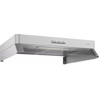


| Brand | Cylinda |
| Model | SOLO SK161RF-10 |
| Product Type | Range Hood |
| Installation Type | Wall-mounted |
| Dimensions (W x D x H) | 598 x 500 x 435 mm |
| Weight | 11.5 kg |
| Power Supply | 220-240 V, 50 Hz |
| Max Extraction Rate | 650 m³/h |
| Noise Level (max speed) | 65 dB(A) |
| Number of Speeds | 3 |
| Filter Type | Aluminum Grease Filter |
| Carbon Filter | Optional (sold separately) |
| Lighting | LED, 2 x 1.5 W |
| Control Type | Push buttons |
| Energy Efficiency Class | A+ |
| Annual Energy Consumption | 35.2 kWh |
| Air Extraction Outlet Diameter | 150 mm |
| Grease Filter Cleaning | Dishwasher safe |
| Replacement Carbon Filter | Filter code: 500900 |
| Warranty | 2 years |
Frequently Asked Questions - SOLO SK161RF-10 Cylinda
User questions about SOLO SK161RF-10 Cylinda
0 question about this device. Answer the ones you know or ask your own.
Ask a new question about this device
Download the instructions for your Range hood in PDF format for free! Find your manual SOLO SK161RF-10 - Cylinda and take your electronic device back in hand. On this page are published all the documents necessary for the use of your device. SOLO SK161RF-10 by Cylinda.
USER MANUAL SOLO SK161RF-10 Cylinda
SPISKÅPA SOLO
COOKER HOOD SOLO
SK151-10, SK161-10, SK171-10
SK161RF-10

INSTRUCTIONS FOR USE
Safety Instructions 6
Instructions for use...... 8
Servicing and warranty.... 10
Electrical installation 11
Installation.... 12
Adjusting air flow 14
A B C
Fig.1
A. Lighting.
Fig.2
www.cylinda.se/service
Please read this installation and user guide carefully before installing and using the product, paying special attention to the safety instructions.
Keep the instructions for reference or for the next owner.
Disconnect the product from the power supply prior to cleaning or maintenance.
§ The diversion of exhaust air must be carried out in accordance with instructions issued by the appropriate authority. § Exhaust air must not be directed into flues that are used for fumes from items such as gas, wood or oil-burning stoves or fireplaces. § The distance between the stove and the product must be at least 44 cm. For gas hobs, the distance should be increased to 65 cm. Adjust accordingly if the stove manufacturer recommends a higher mounting height. N.B. If the product has a stove alarm or stove guard, it must not be mounted over a gas hob. See separate instructions. § You must not flambé food underneath the product.
§ For safety reasons, the installation and replacement of cables or other types of connectors should only be carried out by a qualified professional. § If the product is to be used at the same time as products that use energy sources other than electricity, i.e., gas hobs, gas, wood or oil-burning stoves or fireplaces, etc, the room must have an adequate supply of air. § The product may be used by children from 8 years of age and persons with mental, sensory or physical impairment, or a lack of experience and knowledge, provided they are given information about how the product is to be used. § Children should not be allowed to play with the product. Children must not undertake cleaning or maintenance of the product unsupervised. § Accessible parts of the product may become hot when food is being prepared. § A fire is more likely to spread if the product is not cleaned as frequently as indicated.
N.B. The developer or proprietor is responsible for ensuring installation is carried out correctly and complies with the applicable building regulations.
GENERAL INFORMATION
The product features LED lighting (6.5 W), aluminium filters and the Easy Clean system.
FUNCTIONS

Fig. 1
A. Lighting.
B. Damper function. Open/close.
C. 1. Extension of timer (30 minutes). 2. Filter guard. If the filter guard is activated (see Programming below), the LED will flash when the filter needs to be cleaned. After cleaning, press button C for 2 seconds to reset the system.
The damper will close automatically after 60 minutes or if you press button B again.
It is a good idea to have the damper open a short while before and after cooking to prevent cooking smells spreading into the room.
The product is fitted with a filter guard. To activate/deactivate the filter guard, see below.
Programming
- Start programming: Depress buttons A and B for 3 seconds so that they both flash 3 times. Programming mode will then be active for 30 seconds.
- Select function: Press the button for the selected function to activate/deactivate the function.
| Button Functions |
| C Filter guard |
The LED on the button lights up when the function is activated.
- To save a programme: Keep buttons A and B depressed for 3 seconds. Buttons A and B will flash twice to show that the programme has been saved.
Attention!
If the product has a stove alarm or stove guard, see separate instructions.
CARE AND MAINTENANCE
Cleaning the filter
The cooker hood should be cleaned with a damp cloth and washing-up liquid. With normal usage, the filters must be cleaned at least every other month. Clean more often after intensive use.

Fig. 2
Remove the grease filter by opening the snap retainer, Fig. 2.
Handle the filter carefully, taking care not to bend it.
Soak the filter in a solution of warm water and washing-up liquid. The filter can also be washed in a dishwasher.
Refit the grease filter after cleaning, making sure it snaps firmly into place.
Cleaning other parts
The inside of the cooker hood and the damper must be cleaned at least twice a year.
The damper must be thoroughly cleaned in both its open and closed position using a damp cloth and washing-up liquid. Handle the damper carefully.
TROUBLESHOOTING
Check that the fuse is intact. Go through all the functions to check what is not working. Start by disconnecting the product from the power supply and switching it on again. Check that the connector is not bent or twisted at the connection point.
Attention!
If the product has a stove alarm or stove guard, use the separate instructions for troubleshooting.
SERVICING
Fig. 3
Before contacting servicing, check the product label and note down the FUN number, S/N number and manufacturing date of the product.
The product label is located on the left side, underneath the filter/bottom plate.
Contact Cylinda Service
tel. +46 0771-25 25 00 or visit:
www.cylinda.se/service
They can help you fix the problem or refer you to the nearest service agent for fast and effective service.
The product is covered by the relevant AP-PLiA provisions.
ENVIRONMENTAL INFORMATION
The main raw materials used in the product are:
- Metals: stainless sheet metal, galvanised sheet metal, zinc, aluminium
- Plastics: polypropylene, polyamide, polycarbonate, polybutylene terephthalate (PBT)
- Glass
All components comply with the RoHS Directive.
PACKAGING AND PRODUCT RECYCLING
The packaging should be deposited at your nearest recycling point.

The symbol means that the product must not be treated as household waste. It should instead be taken to a collection point for the recycling of electrical and electronic components. By ensuring that the product is dealt with in the correct manner, you are helping to prevent the adverse environmental and health effects that could arise if the product was disposed of as regular waste. For further information on recycling, contact your local authority or waste disposal service, or the store where you purchased your product.
ELECTRICAL INSTALLATION
ELECTRICAL INSTALLATION
ELECTRICAL INSTALLATION
Electrical connection for 230 V~ earthed.
The product is supplied with a cable and earthed plug for connection to an earthed socket. The socket should be accessible after installation is complete. The junction box or wall socket must be accessible after installation is complete. If the connector is damaged, it must be replaced with an equivalent special cable from the manufacturer or their service agent.
INSTALLATION
INSTALLATION
INSTALLATION
INSTALLATION


ADJUSTING AIR FLOW
ADJUSTING AIR FLOW
ADJUSTING AIR FLOW
ADJUSTING AIR FLOW
Note! Damper adjustment or speed changes must be carried out by a qualified professional.
Adjusting damper: Basic ventilation is set by moving the sliding damper. The damper becomes accessible for adjustment by removing the grease filter.

Basic ventilation: Open the damper by pressing button B. Loosen stop lug G by rotating it 180° (Torx/star screwdriver 10). Set the stop lug to the desired position. The markings on the damper correspond to the values in the “Basic flow” diagram – see following pages. The marking in the picture corresponds to position G4 in the diagram. Lock the stop lug. N.B. Make sure the lug is fully locked. Close the damper by pressing button B on the circuit breaker. Measure the pressure (Pm) at test point A to check that the flow is as required.

Forced ventilation
Forced ventilation
Loosen stop lug F by rotating it 180° (Torx/star screwdriver 10). Set the stop lug to the desired position. The markings on the damper correspond to the values in the "Forcing flow" diagram – see following pages. The marking in the picture corresponds to position F8 in the diagram. Lock the stop lug. N.B. Make sure the lug is fully locked. Open the damper by pressing button B on the circuit breaker. Measure the pressure (Pm) at test point A to check that the flow is as required.
BASIC VENTILATION
Adjustment diagram Adjustment diagram
Measure valve pressure

LpW
- The A-weighted sound power level relative to 1 pW The A-weighted sound power level relative to 1 pW The A-measured sound pressure level relative to 1pW
LpA
LpW = The A-weighted sound power level relative to 1 pW The A-weighted sound power level relative to 1 pW The A-measured sound pressure level relative to 1pW LpA = The A-weighted sound pressure level at 10 m² Sabin The A-weighted sound pressure level at 10 m² Sabin The A-measured sound pressure level at 10 m² Sabin
Real pressure in ventilation duct
Fig.4
Service
We have service throughout Sweden / Nationwide service in Sweden
Visit www.cylinda.se / Visit www.cylinda.se
Call 0771-25 25 00 (local rate only) / Call 0771-25 25 00
Declare / Declare
Machine type / Model code
Serial number / Serial number
Purchase date
Problem description


- INSTRUCTIONS FOR USE
- FIG
- WWW.CYLINDA.SE/SERVICE
- GENERAL INFORMATION
- FUNCTIONS
- PROGRAMMING
- ATTENTION
- CARE AND MAINTENANCE
- CLEANING THE FILTER
- CLEANING OTHER PARTS
- TROUBLESHOOTING
- CONTACT CYLINDA SERVICE
- ENVIRONMENTAL INFORMATION
- PACKAGING AND PRODUCT RECYCLING
- ELECTRICAL INSTALLATION
- FORCED VENTILATION
- BASIC VENTILATION
- SERVICE
- DECLARE / DECLARE
Brand : Cylinda
Model : SOLO SK161RF-10
Category : Range hood