
WV-SPV781 - Surveillance Camera PANASONIC - Free user manual and instructions
Find the device manual for free WV-SPV781 PANASONIC in PDF.
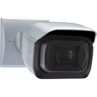


| Product Type | Network Security Camera |
| Model | WV-SPV781 |
| Brand | Panasonic |
| Resolution | 5 Megapixels (2592x1944) |
| Frame Rate | Up to 30 fps @ 5MP |
| Lens | Varifocal, 2.8-10mm, F1.6 |
| Night Vision | IR LEDs, up to 50m range |
| Field of View | 100° (Wide) to 30° (Tele) |
| Minimum Illumination | 0.05 lux (Color), 0.01 lux (B/W), 0 lux (IR On) |
| Compression | H.265, H.264, MJPEG |
| Network Interface | RJ-45 10/100/1000 Mbps, PoE (IEEE 802.3af) |
| Audio | Built-in microphone, audio line out |
| Storage | MicroSD card slot (up to 512GB) |
| Ingress Protection | IP66 (Weatherproof) |
| Dimensions (WxHxD) | 140 x 110 x 105 mm |
| Weight | 950 g |
| Power Supply | PoE (802.3af) or 12V DC, 500mA |
| Power Consumption | Max 12W (IR on) |
| Operating Temperature | -30°C to 60°C (-22°F to 140°F) |
| Main Functions | Motion detection, tamper alarm, privacy masking, edge recording, i-PRO AI analytics |
| Maintenance & Cleaning | Clean lens with soft cloth; check IR LEDs periodically; keep firmware updated |
| Safety | Supports HTTPS, IEEE 802.1X, IP address filtering |
| Spare Parts | Contact authorized Panasonic service center for replacement parts |
| General Information | Warranty: 2 years; User manual available for download |
Frequently Asked Questions - WV-SPV781 PANASONIC
User questions about WV-SPV781 PANASONIC
0 question about this device. Answer the ones you know or ask your own.
Ask a new question about this device
Download the instructions for your Surveillance Camera in PDF format for free! Find your manual WV-SPV781 - PANASONIC and take your electronic device back in hand. On this page are published all the documents necessary for the use of your device. WV-SPV781 by PANASONIC.
USER MANUAL WV-SPV781 PANASONIC
Included Installation Instructions
Network Camera
WV-SPV781L


- This manual describes the installation procedures, network camera installation, cable connections, and field-of-view adjustment.
- Before reading this manual, be sure to read the Important Information
For U.S. and Canada:
Panasonic System Communications
Company of North America, Unit of Panasonic Corporation
Unit of Panasonic of North America
www.panasonic.com/business/
For customer support, call 1.800.528.6747 Two Riverfront Plaza, Newark, NJ 07102-5490
Panasonic Canada Inc.
5770 Ambier Drive, Mississauga.
Ontario, L4W 2T3 Canada
(905)624-5010 www.panasonic.ca
© Panasonic System Networks Co., Ltd. 2015
For Europe and other countries:
Panasonic Corporation
http://www.panasonic.com
[Non-Text]
Panasonic System Networks Co., Ltd.

Authorised Representative in EU:
Panasonic Testing Centre
Panasonic Marketing Euro Winsbergring 15, 32525 H
Winsberghing 10, E2020 Hamburg, Germany
PGQX1821YA Cs0615-1075 Printed in China
[Non-Text]
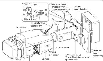
Major operating controls
The component names of the camera are as follows. Refer to the illustration when

Standard accessories Making con
Important Information 1 pc. Installation Guide (this document) 1 set
Warranty card .... 1 set CD-ROM .... 1 pc Code label 2 .... 1 pc. Camera caution label.... 1 pc
*1 The CD-ROM contains the operating instructions and different kinds of tool software programs.
*2 This label may be required for network management. The network administrator shall retain the code label
The following parts are used during installation procedures.
④ Camera mount bracket cover 2 pcs. ① Wire lug fixing screw
⑧ Camera mount bracket cover fixing screw M3 x 10 mm {3/8 inches} ...... 2 pcs.
(M3 x 6 mm {1/4 inches}) .... 3 pcs. (incl. 1 spare)
( incl. 1 spare) Ⓐ Safety wire lug .... 1 pc. © Waterproof tape 1 pc Ⓧ Protection cover 1 pc
① LAN connector cover 1 pc. ② Adapter box 1 pc.
⑤ 4P alarm cable .... 1 pc. Ⓜ Mounting screws for adapter box (M5 × 20
① 2P power cable .... 1 pc. mm (13/16 inches)) .... 5 pcs.
(H) Safety wire 1 pc. (or them, 1 for spare)
(M4 × 35 mm {1- 3/8 inches})
*3 The audio/monitor output cable can be switched to be used as MONITOR OUT using the
software. The MONITOR OUT conversion plug is used to connect the camera to the auditor monitor output cable and to convert a storage mini jack (e3 5 mm) [1/8 inch] into an RCA pin
output jack.
K Protection
cover (installed)
NTSC/PAL switch
• Switches the MONITOR OUT terminal output between NTSC and PAL.
Notes:
- Use a thin, non-conductive tool to press the switch.
(四)预计未来三年
NITIAL SET BUTTON
How to initialize the camera allow the steps below to initis
Turn off the power of the camera. When using a PoE
When using an external power supply, disconnect the 2P power cable plug from the camera.
Turn on the power of the camera while holding down the INITIAL SET button, and then keep holding down the button for 5 seconds or more. About 3 minutes after you have released the INITIAL SET but
ton, the camera will start up and the settings including the network settings will be initialized.
IMPORTANT:
- When the camera is initialized, the settings including the network settings will be initialized.
Note that the CRT key (SSL encryption key) used for the HTTPS protocol will not be initialized.
- Before initializing the settings, it is recommended to write down the settings in advance. - Do not turn off the power of the camera during the process of initialization. Otherwise, it may
Do not learn on the power of the camera during the process of initialization. Otherwise, it may fail to initialize and may cause malfunction.
SD ON/OFF button
① When the SD ON/OFF button is pressed for less than 1 second, the SD MOUNT indicator is lit green
and data can be saved to the SD memory card 1 .
② When the SD ON/OFF button is held down for about 2 seconds, the SD MOUNT indicator goes out, and the SD memory card can be removed.
SD MOUNT indicator
- When an SD memory
- When an ED memory card is inserted and could be recognized - Lights off → Brinks green → Lights off
- When data can be saved after the SD memory card is inserted Lights off → Lights green and the SD ON/OFF button is opened (for less than 4 seconds).
and the SD ON/OFF button is pressed (for less than 1 second) - When data can be saved to the SD memory card. Lights green
- When data can be saved to the SD memory card - When the SD memory card is removed after holding down Lights green → Blinks gree
the SD ON/OFF button for about 2 seconds Lights off (recording)
Lights off (waiting for recording)
- When data cannot be saved to the SD memory card because Lights off
an abnormality was detected of the SD memory card is configured not to be used.
0
SD ERROR/AI Indicator - When AE (Auto Focus) o
- When A# (Halo Focus) operation is being executed - When the camera is being started - Lights red
- When an SD memory card is recognized normally Lights red → Lights off
- When the SD memory card slot is not used or an abnormality Lights red → Stays red
is detected in SD memory card after the camera has started
ACT indicator
- When data is being sent via the network camera Blinks green (accessing)
LINK indicator
- When the camera is able to communicate with the Lights orange
connected device
nections
Turn off each system's power supply before making a connection. Before making connections,
Connect a LAN cable (category 5 or better, straight)
IMPORTANT
- Use all 4 pairs (8 pins) of the LAN cable (category 5 or better, straight).
• The maximum cable length is 100 m {328 feet}.
- Make sure that the PoE device in use is compliant with IEEE802.3af standard.
- When connecting both the 12 V DC power supply and the PoE device for power supply, 12 V DC will be used for power supply.
* If a 12 V DC power supply and a PoE hub
work connections may not be possible. In this case, disable the PoE settings. Refer
to the operating instructions of the PoE hub or router in use.
* Depending on the PoE device used, if you stop the 12 V DC power supply after operation it and a PoE input computer at the same time, the power supply was
operating it and a PoE hub of router at the same time, the power supply may stop causing the camera to restart.
- When the LAN cable is disco
onds. When the cable is quickly reconnected, the power may not be supplied from
the PoE device.
- When cables are used outdoors, there is a chance that they may be affected by lightning. In this case, install a lightning ammeter just before where the LAN cable can
Hing. in this case, install a lightning arrester just before where the LAN cable connects to the camera.
![graph TD A["RJ45 (female) Network cable"] --> B["Alarm input/output cable (External I/O terminal)"] B --> C["Power cable (12 V DC)"] C --> D["Microphone/inline input cable (white)"] D --> E["Audiomonitor output cable (black)"] F["LAN cable (category 5 or better, straight)"] --> G["4P alarm cable (ac…](/content/2026/07/1514129/images/d0970ba733498e1d981e2334d7b3d3bc08639b455891dc90c6750d5aa550d4a3.jpg)
Microphone/line input cable
Connect a stereo mini plug (ø3.5 mm {1/8 inches})
- Input impedance: Approx. 2 kΩ (unbalanced)
- Recommended cable length: Less than 1 m (3.28 feet) (for microphone input) Less than
10 m (32.8 feet) (for line input)
- Recommended microphone: Plug-in power type (option)
- Supply voltage: 2.5 V ±0.5 V - Recommended sensitivity of microphone: -48 dB ±3 dB (0 dB=1 V/Pa,1 kHz)
- Input level for line input: Approx. -10 dBV
Waterproof treatment for the cable joint sections
Adequate waterproof treatment is required for the cables when installing the camera with cables
The camera body is waterproof, but the cable ends are not waterproof. Be sure to use the sup-
plied waterproof tape at the points where the cables are connected to apply waterproof treatment in the following procedure.
Failure to observe this or use of a tape other than the provided waterproof tape (such as a vinyl tape) may cause water leakage resulting in malfunction.
p2, p3, p4


Cite
Stretch the tape to
approx, twice its length
- approx. twice no longer.
2x

① LAN connector cover
(accessory)
1
→

Connect the alarm input/output cable
④P alarm cable (accessory)
F
195 GND (BLACK)
135 ALARM INS, AUX OUT, DAY/NIGHT OUT (gray) (Alarm input 3, AUX output, DAY/NIGHT switchi
ALARM IN2, ALARM OUT (red) (Alarm input 2, Alarm output)
ALARM IN1, DAY/NIGHT IN (green) (Alarm input 1/ DAY/NIGHT switching input)
- ALARM IN1@DAY/NIGHT IN), ALARM IN2, ALARM IN3
Input specification: No-voltage make contact input (4 V - 5 V DC, internally pulled up)
OFF: Open or 4 V - 5 V DC ON: Make contact with CND
ON: Make contact with GND (required drive current. Tink or More) - ALARM OUT. AUX OUT (DAY/NIGHT OUT)
Output specification: Open collector output (m
Open: 4 V - 5 V DC by internal pull-up
Close: Output voltage 1 V DC or less (ma: * The default of EXT 10 terminals is "Off"
The delta
IMPORTANT:
- Be sure to use the E 4P alarm cable (accessory) provided with this product. - Install external devices so that they do not exceed the ratings above.
- Install external devices so that they do not exceed the ratings above. - When using the external I/O terminals as the output terminals, ensure they do not
cause signal collision with external signals.
Note:
• Off
- Oil, input, and output of the external I/O terminal 2 and 3 can be switched by configuring the setting. Refer to the Operating Instructions on the provided CD-ROM for further
information about the external I/O terminal 2 and 3 (ALARM IN2, 3) settings ("Off",
"Alarm input", "Alarm output", "AUX output" or "DAY/NIGHT switching output").
Connect the power cable
Caution:
- A READILY ACCESSIBLE DISCONNECT DEVICE SHALL BE INCORPORATED TO THE EQUIPMENT POWERED
BE INCORPORATED TO THE EQUIPMENT POWERED BY 12 V DC POWER SUPPLY
• ONLY CONNECT 12 V DC CI
1310/CSA 223) or LIMITED POWER SOURCE (IEC/EN/LL/CSA 60950.1)
ULCSA 00850-1).
connect the output cable of the AC adaptor to the Ⓗ 2P power cable (accessory).
IMPORTANT:
- Use 12 V DC power supply that is insulated from the commercial AC power.
- Be sure to use the F 2P power cable (accessory) provided with this product. - Be sure to fully insert the F 2P power cable (accessory) into the 13 V DC power cup.
- Be sure to fully insert the 2F power cable (accessory) into the 12 V DC p nly terminal. Otherwise, it may damage the camera or cause malfunction
- When installing the camera, make sure that excessive force is not applied to the
power cable.
- Be sure to use an AC adaptor compliant with the specifications (written in the indication label on the bottom side of this unit) regarding power sources and power consumption.
label on the bottom side of this unit) regarding power source and power consumption.
Connect an external amplifier-embedded speaker to the audio/
onitor output cable
connect a stereo mini plug (ø3.5 mm (1/8 inches)).* Use an external powered speaker
- Output impedance: Approx. 600 Ω (unbalanced
- Recommended cable length: Less than 10 in (32.8 feet) - Output level: -20 dBV (can switch to monitor output)
- SUPERIOR: 25 DEY (SEVIATION OF METERIAL CEIPE),
IMPORTANT:
- Connect/disconnect the audio cables and turn on the power of the camera after turn
ing off the power of the audio output devices. Otherwise, loud noise may be heard
from the speaker • Make sure that
- Make sure that the stereo mini plug is connected to this table. When a monaural mini plug is connected, audio may not be heard. When connecting a monaural speaker
with amplifier, use a locally procured conversion cable (mono-stereo).
When connecting to a network using a PoE hub
ore starting the installation, check the entire system configuration
The following illustration gives a wiring example of how to connect the camera to the network via a PoF device (hub).
![graph TD A["Analog monitor"] --> B["Adjustment monitor"] B --> C["Powered speaker"] C --> D["Microphone"] D --> E["PC"] E --> F["LAN cable (category 5 or better, straight)"] F --> G["PIeE device (hub)"] G --> H["Computer"]](/content/2026/07/1514129/images/1cec2cdf4d49d7fcda2b99fd28bc78012944a805facdfdacee3eb163650794c2.jpg)
LAN cable (category 5 or better, straight)
Use a LAN cable (category 5 or better, cross) when directly connecting the camera to a PC.
IMPORTANT
- The adjustment monitor is used to adjust the field of view when installing or servicing
the camera. It is not provided for recording/monitoring use.
- Depending on the adjustment monitor, some characters (camera title, preset ID, etc.) may not be displayed on the screen.
- Use a switching hub or a router wh
- Use is switching hub of a router which is compliant with TOBASE-17/TOBASE-TX - If a PoE hub is not used, each network camera must be connected to a 12 V DC
power supply.
- When using 12 V DC, power supply from a PoE hub or router is not required.
| Step1 Preparations | Step2 Attaching the safety wire | Step3 Fixing the camera | Step4 Adjusting the camera | Step5 Perform camera settings (see the separate leaflet) | ||||
| Installation method | Recom- mended screw | Minimum pull- out strength | 1 Wire lug fixing screw (accessory) 2 Safety wire lug (accessory) 3 The safety wire is not shown in the subsequent illustrations. | |||||
| [1] Directly mount the camera onto the ceiling or wall (when there is a space for wiring in the ceiling or the wall) | M5 screws x 4 | 724 N (163 bf) (per 1 pc.) | 1 Wire wire lug (accessory) 2 Safety wire lug (accessory) 3 Safety wire lug (accessory) 4 Safety wire lug (accessory) 5 Safety wire lug (accessory) 6 Safety wire lug (accessory) 7 Safety wire lug (accessory) 8 Safety wire lug (accessory) 9 Safety wire lug (accessory) 10 Safety wire lug (accessory) 11 Safety wire lug (accessory) 12 Safety wire lug (accessory) 13 Safety wire lug (accessory) 14 Safety wire lug (accessory) 15 Safety wire lug (accessory) 16 Safety wire lug (accessory) 17 Safety wire lug (accessory) 18 Safety wire lug (accessory) 19 Safety wire lug (accessory) 20 Safety wire lug (accessory) 21 Safety wire lug (accessory) 22 Safety wire lug (accessory) 23 Safety wire lug (accessory) 24 Safety wire lug (accessory) 25 Safety wire lug (accessory) 26 Safety wire lug (accessory) 27 Safety wire lug (accessory) 28 Safety wire lug (accessory) 29 Safety wire lug (accessory) 30 Safety wire lug (accessory) 31 Safety wire lug (accessory) 32 Safety wire lug (accessory) 33 Safety wire lug (accessory) 34 Safety wire lug (accessory) 35 Safety wire lug (accessory) 36 Safety wire lug (accessory) 37 Safety wire lug (accessory) 38 Safety wire lug (accessory) 39 Safety wire lug (accessory) 40 Safety wire lug (accessory) 41 Safety wire lug (accessory) 42 Safety wire lug (accessory) 43 Safety wire lug (accessory) 44 Safety wire lug (accessory) 45 Safety wire lug (accessory) 46 Safety wire lug (accessory) 47 Safety wire lug (accessory) 48 Safety wire lug (accessory) 49 Safety wire lug (accessory) 50 Safety wire lug (accessory) 51 Safety wire lug (accessory) 52 Safety wire lug (accessory) 53 Safety wire lug (accessory) 54 Safety wire lug (accessory) 55 Safety wire lug (accessory) 56 Safety wire lug (accessory) 57 Safety wire lug (accessory) 58 Safety wire lug (accessory) 59 Safety wire lug (accessory) 60 Safety wire lug (accessory) 61 Safety wire lug (accessory) 62 Safety wire lug (accessory) 63 Safety wire lug (accessory) 64 Safety wire lug (accessory) 65 Safety wire lug (accessory) 66 Safety wire lug (accessory) 67 Safety wire lug (accessory) 68 Safety wire lug (accessory) 69 Safety wire lug (accessory) 70 Safety wire lug (accessory) 71 Safety wire lug (accessory) 72 Safety wire lug (accessory) 73 Safety wire lug (accessory) 74 Safety wire lug (accessory) 75 Safety wire lug (accessory) 76 Safety wire lug (accessory) 77 Safety wire lug (accessory) 78 Safety wire lug (accessory) 79 Safety wire lug (accessory) 80 Safety wire lug (accessory) 81 Safety wire lug (accessory) 82 Safety wire lug (accessory) 83 Safety wire lug (accessory) 84 Safety wire lug (accessory) 85 Safety wire lug (accessory) 86 Safety wire lug (accessory) 87 Safety wire lug (accessory) 88 Safety wire lug (accessory) 89 Safety wire lug (accessory) 90 Safety wire lug (accessory) 91 Safety wire lug (accessory) 92 Safety wire lug (accessory) 93 Safety wire lug (accessory) 94 Safety wire lug (accessory) 95 Safety wire lug (accessory) 96 Safety wire lug (accessory) 97 Safety wire lug (accessory) 98 Safety wire lug (accessory) 99 Safety wire lug (accessory) 100 Safety wire lug (accessory) 101 Safety wire lug (accessory) 102 Safety wire lug (accessory) 103 Safety wire lug (accessory) 104 Safety wire lug (accessory) 105 Safety wire lug (accessory) 106 Safety wire lug (accessory) 107 Safety wire lug (accessory) 108 Safety wire lug (accessory) 109 Safety wire lug (accessory) 110 Safety wire lug (accessory) 111 Safety wire lug (accessory) 112 Safety wire lug (accessory) 113 Safety wire lug (accessory) 114 Safety wire lug (accessory) 115 Safety wire lug (accessory) 116 Safety wire lug (accessory) 117 Safety wire lug (accessory) 118 Safety wire lug (accessory) 119 Safety wire lug (accessory) 120 Safety wire lug (accessory) 121 Safety wire lug (accessory) 122 Safety wire lug (accessory) 123 Safety wire lug (accessory) 124 Safety wire lug (accessory) 125 Safety wire lug (accessory) 126 Safety wire lug (accessory) 127 Safety wire lug (accessory) 128 Safety wire lug (accessory) 129 Safety wire lug (accessory) 130 Safety wire lug (accessory) 131 Safety wire lug (accessory) 132 Safety wire lug (accessory) 133 Safety wire lug (accessory) 134 Safety wire lug (accessory) 135 Safety wire lug (accessory) 136 Safety wire lug (accessory) 137 Safety wire lug (accessory) 138 Safety wire lug (accessory) 139 Safety wire lug (accessory) 140 Safety wire lug (accessory) 141 Safety wire lug (accessory) 142 Safety wire lug (accessory) 143 Safety wire lug (accessory) 144 Safety wire lug (accessory) 145 Safety wire lug (accessory) 146 Safety wire lug (accessory) 147 Safety wire lug (accessory) 148 Safety wire lug (accessory) 149 Safety wire lug (accessory) 150 Safety wire lug (accessory) 151 Safety wire lug (accessory) 152 Safety wire lug (accessory) 153 Safety wire lug (accessory) 154 Safety wire lug (accessory) 155 Safety wire lug (accessory) 156 Safety wire lug (accessory) 157 Safety wire lug (accessory) 158 Safety wire lug (accessory) 159 Safety wire lug (accessory) 160 Safety wire lug (accessory) 161 Safety wire lug (accessory) 162 Safety wire lug (accessory) 163 Safety wire lug (accessory) 164 Safety wire lug (accessory) 165 Safety wire lug (accessory) 166 Safety wire lug (accessory) 167 Safety wire lug (accessory) 168 Safety wire lug (accessory) 169 Safety wire lug (accessory) 170 Safety wire lug (accessory) 171 Safety wire lug (accessory) 172 Safety wire lug (accessory) 173 Safety wire lug (accessory) 174 Safety wire lug (accessory) 175 Safety wire lug (accessory) 176 Safety wire lug (accessory) 177 Safety wire lug (accessory) 178 Safety wire lug (accessory) 179 Safety wire lug (accessory) 180 Safety wire lug (accessory) 181 Safety wire lug (accessory) 182 Safety wire lug (accessory) 183 Safety wire lug (accessory) 184 Safety wire lug (accessory) 185 Safety wire lug (accessory) 186 Safety wire lug (accessory) 187 Safety wire lug (accessory) 188 Safety wire lug (accessory) 189 Safety wire lug (accessory) 190 Safety wire lug (accessory) 191 Safety wire lug (accessory) 192 Safety wire lug (accessory) 193 Safety wire lug (accessory) 194 Safety wire lug (accessory) 195 Safety wire lug (accessory) 196 Safety wire lug (accessory) 197 Safety wire lug (accessory) 198 Safety wire lug (accessory) 199 Safety wire lug (accessory) 200 Safety wire lug (accessory) 201 Safety wire lug (accessory) 202 Safety wire lug (accessory) 203 Safety wire lug (accessory) 204 Safety wire lug (accessory) 205 Safety wire lug (accessory) 206 Safety wire lug (accessory) 207 Safety wire lug (accessory) 208 Safety wire lug (accessory) 209 Safety wire lug (accessory) 210 Safety wire lug (accessory) 211 Safety wire lug (accessory) 212 Safety wire lug (accessory) 213 Safety wire lug (accessory) 214 Safety wire lug (accessory) 215 Safety wire lug (accessory) 216 Safety wire lug (accessory) 217 Safety wire lug (accessory) 218 Safety wire lug (accessory) 219 Safety wire lug (accessory) 220 Safety wire lug (accessory) 221 Safety wire lug (accessory) 222 Safety wire lug (accessory) 223 Safety wire lug (accessory) 224 Safety wire lug (accessory) 225 Safety wire lug (accessory) 226 Safety wire lug (accessory) 227 Safety wire lug (accessory) 228 Safety wire lug (accessory) 229 Safety wire lug (accessory) 230 Safety wire lug (accessory) 231 Safety wire lug (accessory) 232 Safety wire lug (accessory) 233 Safety wire lug (accessory) 234 Safety wire lug (accessory) 235 Safety wire lug (accessory) 236 Safety wire lug (accessory) 237 Safety wire lug (accessory) 238 Safety wire lug (accessory) 239 Safety wire lug (accessory) 240 Safety wire lug (accessory) 241 Safety wire lug (accessory) 242 Safety wire lug (accessory) 243 Safety wire lug (accessory) 244 Safety wire lug (accessory) 245 Safety wire lug (accessory) 246 Safety wire lug (accessory) 247 Safety wire lug (accessory) 248 Safety wire lug (accessory) 249 Safety wire lug (accessory) 250 Safety wire lug (accessory) 251 Safety wire lug (accessory) 252 Safety wire lug (accessory) 253 Safety wire lug (accessory) 254 Safety wire lug (accessory) 255 Safety wire lug (accessory) 256 Safety wire lug (accessory) 257 Safety wire lug (accessory) 258 Safety wire lug (accessory) 259 Safety wire lug (accessory) 260 Safety wire lug (accessory) 261 Safety wire lug (accessory) 262 Safety wire lug (accessory) 263 Safety wire lug (accessory) 264 Safety wire lug (accessory) 265 Safety wire lug (accessory) 266 Safety wire lug (accessory) 267 Safety wire lug (accessory) 268 Safety wire lug (accessory) 269 Safety wire lug (accessory) 270 Safety wire lug (accessory) 271 Safety wire lug (accessory) 272 Safety wire lug (accessory) 273 Safety wire lug (accessory) 274 Safety wire lug (accessory) 275 Safety wire lug (accessory) 276 Safety wire lug (accessory) 277 Safety wire lug (accessory) 278 Safety wire lug (accessory) 279 Safety wire lug (accessory) 280 Safety wire lug (accessory) 281 Safety wire lug (accessory) 282 Safety wire lug (accessory) 283 Safety wire lug (accessory) 284 Safety wire lug (accessory) 285 Safety wire lug (accessory) 286 Safety wire lug (accessory) 287 Safety wire lug (accessory) 288 Safety wire lug (accessory) 289 Safety wire lug (accessory) 290 Safety wire lug (accessory) 291 Safety wire lug (accessory) 292 Safety wire lug (accessory) 293 Safety wire lug (accessory) 294 Safety wire lug (accessory) 295 Safety wire lug (accessory) 296 Safety wire lug (accessory) 297 Safety wire lug (accessory) 298 Safety wire lug (accessory) 299 Safety wire lug (accessory) 300 Safety wire lug (accessory) 301 Safety wire lug (accessory) 302 Safety wire lug (accessory) 303 Safety wire lug (accessory) 304 Safety wire lug (accessory) 305 Safety wire lug (accessory) 306 Safety wire lug (accessory) 307 Safety wire lug (accessory) 308 Safety wire lug (accessory) 309 Safety wire lug (accessory) 310 Safety wire lug (accessory) 311 Safety wire lug (accessory) 312 Safety wire lug (accessory) 313 Safety wire lug (accessory) 314 Safety wire lug (accessory) 315 Safety wire lug (accessory) 316 Safety wire lug (accessory) 317 Safety wire lug (accessory) 318 Safety wire lug (accessory) 319 Safety wire lug (accessory) 320 Safety wire lug (accessory) 321 Safety wire lug (accessory) 322 Safety wire lug (accessory) 323 Safety wire lug (accessory) 324 Safety wire lug (accessory) 325 Safety wire lug (accessory) 326 Safety wire lug (accessory) 327 Safety wire lug (accessory) 328 Safety wire lug (accessory) 329 Safety wire lug (accessory) 330 Safety wire lug (accessory) 331 Safety wire lug (accessory) 332 Safety wire lug (accessory) 333 Safety wire lug (accessory) 334 Safety wire lug (accessory) 335 Safety wire lug (accessory) 336 Safety wire lug (accessory) 337 Safety wire lug (accessory) 338 Safety wire lug (accessory) 339 Safety wire lug (accessory) 340 Safety wire lug (accessory) 341 Safety wire lug (accessory) 342 Safety wire lug (accessory) 343 Safety wire lug (accessory) 344 Safety wire lug (accessory) 345 Safety wire lug (accessory) 346 Safety wire lug (accessory) 347 Safety wire lug (accessory) 348 Safety wire lug (accessory) 349 Safety wire lug (accessory) 350 Safety wire lug (accessory) 351 Safety wire lug (accessory) 352 Safety wire lug (accessory) 353 Safety wire lug (accessory) 354 Safety wire lug (accessory) 355 Safety wire lug (accessory) 356 Safety wire lug (accessory) 357 Safety wire lug (accessory) 358 Safety wire lug (accessory) 359 Safety wire lug (accessory) 360 Safety wire lug (accessory) 361 Safety wire lug (accessory) 362 Safety wire lug (accessory) 363 Safety wire lug (accessory) 364 Safety wire lug (accessory) 365 Safety wire lug (accessory) 366 Safety wire lug (accessory) 367 Safety wire lug (accessory) 368 Safety wire lug (accessory) 369 Safety wire lug (accessory) 370 Safety wire lug (accessory) 371 Safety wire lug (accessory) 372 Safety wire lug (accessory) 373 Safety wire lug (accessory) 374 Safety wire lug (accessory) 375 Safety wire lug (accessory) 376 Safety wire lug (accessory) 377 Safety wire lug (accessory) 378 Safety wire lug (accessory) 379 Safety wire lug (accessory) 380 Safety wire lug (accessory) 381 Safety wire lug (accessory) 382 Safety wire lug (accessory) 383 Safety wire lug (accessory) 384 Safety wire lug (accessory) 385 Safety wire lug (accessory) 386 Safety wire lug (accessory) 387 Safety wire lug (accessory) 388 Safety wire lug (accessory) 389 Safety wire lug (accessory) 390 Safety wire lug (accessory) 391 Safety wire lug (accessory) 392 Safety wire lug (accessory) 393 Safety wire lug (accessory) 394 Safety wire lug (accessory) 395 Safety wire lug (accessory) 396 Safety wire lug (accessory) 397 Safety wire lug (accessory) 398 Safety wire lug (accessory) 399 Safety wire lug (accessory) 400 Safety wire lug (accessory) 401 Safety wire lug (accessory) 402 Safety wire lug (accessory) 403 Safety wire lug (accessory) 404 Safety wire lug (accessory) 405 Safety wire lug (accessory) 406 Safety wire lug (accessory) 407 Safety wire lug (accessory) 408 Safety wire lug (accessory) 409 Safety wire lug (accessory) 410 Safety wire lug (accessory) 411 Safety wire lug (accessory) 412 Safety wire lug (accessory) 413 Safety wire lug (accessory) 414 Safety wire lug (accessory) 415 Safety wire lug (accessory) 416 Safety wire lug (accessory) 417 Safety wire lug (accessory) 418 Safety wire lug (accessory) 419 Safety wire lug (accessory) 420 Safety wire lug (accessory) 421 Safety wire lug (accessory) 422 Safety wire lug (accessory) 423 Safety wire lug (accessory) 424 Safety wire lug (accessory) 425 Safety wire lug (accessory) 426 Safety wire lug (accessory) 427 Safety wire lug (accessory) 428 Safety wire lug (accessory) 429 Safety wire lug (accessory) 430 Safety wire lug (accessory) 431 Safety wire lug (accessory) 432 Safety wire lug (accessory) 433 Safety wire lug (accessory) 434 Safety wire lug (accessory) 435 Safety wire lug (accessory) 436 Safety wire lug (accessory) 437 Safety wire lug (accessory) 438 Safety wire lug (accessory) 439 Safety wire lug (accessory) 440 Safety wire lug (accessory) 441 Safety wire lug (accessory) 442 Safety wire lug (accessory) 443 Safety wire lug (accessory) 444 Safety wire lug (accessory) 445 Safety wire lug (accessory) 446 Safety wire lug (accessory) 447 Safety wire lug (accessory) 448 Safety wire lug (accessory) 449 Safety wire lug (accessory) 450 Safety wire lug (accessory) 451 Safety wire lug (accessory) 452 Safety wire lug (accessory) 453 Safety wire lug (accessory) 454 Safety wire lug (accessory) 455 Safety wire lug (accessory) 456 Safety wire lug (accessory) 457 Safety wire lug (accessory) 458 Safety wire lug (accessory) 459 Safety wire lug (accessory) 460 Safety wire lug (accessory) 461 Safety wire lug (accessory) 462 Safety wire lug (accessory) 463 Safety wire lug (accessory) 464 Safety wire lug (accessory) 465 Safety wire lug (accessory) 466 Safety wire lug (accessory) 467 Safety wire lug (accessory) 468 Safety wire lug (accessory) 469 Safety wire lug (accessory) 470 Safety wire lug (accessory) 471 Safety wire lug (accessory) 472 Safety wire lug (accessory) 473 Safety wire lug (accessory) 474 Safety wire lug (accessory) 475 Safety wire lug (accessory) 476 Safety wire lug (accessory) 477 Safety wire lug (accessory) 478 Safety wire lug (accessory) 479 Safety wire lug (accessory) 480 Safety wire lug (accessory) 481 Safety wire lug (accessory) 482 Safety wire lug (accessory) 483 Safety wire lug (accessory) 484 Safety wire lug (accessory) 485 Safety wire lug (accessory) 486 Safety wire lug (accessory) 487 Safety wire lug (accessory) 488 Safety wire lug (accessory) 489 Safety wire lug (accessory) 490 Safety wire lug (accessory) 491 Safety wire lug (accessory) 492 Safety wire lug (accessory) 493 Safety wire lug (accessory) 494 Safety wire lug (accessory) 495 Safety wire lug (accessory) 496 Safety wire lug (accessory) 497 Safety wire lug (accessory) 498 Safety wire lug (accessory) 499 Safety wire lug (accessory) 500 Safety wire lug (accessory) 501 Safety wire lug (accessory) 502 Safety wire lug (accessory) 503 Safety wire lug (accessory) 504 Safety wire lug (accessory) 505 Safety wire lug (accessory) 506 Safety wire lug (accessory) 507 Safety wire lug (accessory) 508 Safety wire lug (accessory) 509 Safety wire lug (accessory) 510 Safety wire lug (accessory) 511 Safety wire lug (accessory) 512 Safety wire lug (accessory) 513 Safety wire lug (accessory) 514 Safety wire lug (accessory) 515 Safety wire lug (accessory) 516 Safety wire lug (accessory) 517 Safety wire lug (accessory) 518 Safety wire lug (accessory) 519 Safety wire lug (accessory) 520 Safety wire lug (accessory) 521 Safety wire lug (accessory) 522 Safety wire lug (accessory) 523 Safety wire lug (accessory) 524 Safety wire lug (accessory) 525 Safety wire lug (accessory) 526 Safety wire lug (accessory) 527 Safety wire lug (accessory) 528 Safety wire lug (accessory) 529 Safety wire lug (accessory) 530 Safety wire lug (accessory) 531 Safety wire lug (accessory) 532 Safety wire lug (accessory) 533 Safety wire lug (accessory) 534 Safety wire lug (accessory) 535 Safety wire lug (accessory) 536 Safety wire lug (accessory) 537 Safety wire lug (accessory) 538 Safety wire lug (accessory) 539 Safety wire lug (accessory) 540 Safety wire lug (accessory) 541 Safety wire lug (accessory) 542 Safety wire lug (accessory) 543 Safety wire lug (accessory) 544 Safety wire lug (accessory) 545 Safety wire lug (accessory) 546 Safety wire lug (accessory) 547 Safety wire lug (accessory) 548 Safety wire lug (accessory) 549 Safety wire lug (accessory) 550 Safety wire lug (accessory) 551 Safety wire lug (accessory) 552 Safety wire lug (accessory) 553 Safety wire lug (accessory) 554 Safety wire lug (accessory) 555 Safety wire lug (accessory) 556 Safety wire lug (accessory) 557 Safety wire lug (accessory) 558 Safety wire lug (accessory) 559 Safety wire lug (accessory) 560 Safety wire lug (accessory) 561 Safety wire lug (accessory) 562 Safety wire lug (accessory) 563 Safety wire lug (accessory) 564 Safety wire lug (accessory) 565 Safety wire lug (accessory) 566 Safety wire lug (accessory) 567 Safety wire lug (accessory) 568 Safety wire lug (accessory) 569 Safety wire lug (accessory) 570 Safety wire lug (accessory) 571 Safety wire lug (accessory) 572 Safety wire lug (accessory) 573 Safety wire lug (accessory) 574 Safety wire lug (accessory) 575 Safety wire lug (accessory) 576 Safety wire lug (accessory) 577 Safety wire lug (accessory) 578 Safety wire lug (accessory) 579 Safety wire lug (accessory) 580 Safety wire lug (accessory) 581 Safety wire lug (accessory) 582 Safety wire lug (accessory) 583 Safety wire lug (accessory) 584 Safety wire lug (accessory) 585 Safety wire lug (accessory) 586 Safety wire lug (accessory) 587 Safety wire lug (accessory) 588 Safety wire lug (accessory) 589 Safety wire lug (accessory) 590 Safety wire lug (accessory) 591 Safety wire lug (accessory) 592 Safety wire lug (accessory) 593 Safety wire lug (accessory) 594 Safety wire lug (accessory) 595 Safety wire lug (access | |||||
| Step 4 Adjusting the camera 1, 2, 3, 4, 5 | D) Using a 5 mm (3/16 inches) hex wrench (locally procured), loosen the Yawing lock screw, turn the camera until the sunshield faces up and adjust the tilt of the cam- |
① Change the direction the camera is facing from directly down to facing up (as shown in the illustration on the lower right) and temporarily fix the camera in place. After this, loosen the 4 fixing screws on the camera front cover and remove the front cover together with the Ⓔ Protection cover (accessory).
IMPORTANT: - The front cover is connected to the camera via the auxiliary wire for mounting the front cover as well as the IR LED cable. Do not remove the auxiliary wire and IR LED cable. - Do not remove the Protection cover (accessory) from the front cover.
② Fit a pin cable (locally procured) to the MONITOR OUT jack on the camera and connect an adjustment monitor.
③ Turn on the camera.
④ Insert an SD memory card into the slot, if necessary. Insert the SD memory card with its label facing the lens. • To remove the SD memory card, hold down
the SD ON/OFF button for about 2 seconds.
When the blinking SD MOUNT indicator go out, you can remove the SD memory cord
- After the SD memory card has been
- After the SD memory card has been replaced, press the SD ON/OFF button (for
less than 1 second), and make sure the SD
MOUNT indicator is continually lit.
- If you do not press the SD ON/OFF button after
replacing the SD memory card, the SD MOUNT indi-
cator is automatically lit approximately 5 minutes later
⑤ Adjust the camera field of view
Adjust the direction of the camera with the PAN, TILT and YAW parts, and press the
WIDE or TELE button until the desired field of view is achieved.
A) Using a 5 mm {3/16 inches} hex wrench (locally procured), loosen the PAN lock screw, either side of the base of camera arm. To direct the camera to the left turn the screw
either side of the base of camera arm. To direct the camera to the left, turn the screw clockwise when viewed from the front. To direct the camera to the right, turn it counter
clockwise when viewed from the front. To direct the camera to the right, turn it counter clockwise. (Panning range: +180° to -180°)
B) Using a 5 mm (3/16 inches) hex wrench (locally procured), loosen the TILT lock sc
in the center of camera arm and roughly adjust the direction of the camera. (Tilting
C) Temporarily tighten 2 RAN lock screws and 1 TIL T lock screw to prevent the same
C) Temporarily tighten 2 PAN lock screws and 1 NET lock screw to prevent the came from moving.
IMPORTANT
IMPORTANT:
- Avoid touching the tilting part near the warning label when you change the tilting angle to secure the cam-
when you change the timing angle to store the camera.
- If the TILT or PAN lock screw is loosened, the camera
may not be held in place when it is secured to the wall or ceiling. If this is the case, temporarily tighten
wall or ceiling. If this is the case, temporarily tighten the appropriate lock screws to keep the camera from
the appropriate form allows to help the camera from moving.
The Ground Truth image displays a single, solid horizontal line. According to Rule 2 (UNDERSCORE & LINE RULES), this is a stylistic or background line, not a placeholder underscore. Therefore, the OCR result must ignore it and output nothing or only meaningful text. The provided OCR content is "____", which consists of four underscores. This is an incorrect interpretation of the line as a placeholder, violating the rule that stylistic lines must be ignored. The OCR has hallucinated underscores where none should exist based on the GT's visual context. Hence, the OCR result is inconsistent with the Ground Truth.


























era.
(Taw range: -115 to +200)
E) Press the WIDE or TELE button to adjust the field of view.
F) Adjust the camera angle and field of view by repeating steps A) through E). When
the desired angle and field of view are achieved, tighten the 2 PAN lock screws,
TILT lock screw and Yawing lock screw.
Recommended tightening torque PAN lock screw: 2.7 N·m (2.0 lbf ft) Tilt Lock screw: 4.0 N·m (3.0 lb fft).
TILT lock screw: 4.3 N m {3.2 lbf ft}
Yawing lock screw: 3.7 N m (3.0 lbf ft)
IMPORTANT:
- After adjustment, be sure to tighten the PAN, TILT and Yawing lock screws.
[EMPTY]
Note:
- Any of the PAN, TILT and YAW lock screws can be adjusted by loosening them about
1 turn. Do not unscrew them more than necessary.
- Make sure the camera is supported when seasoning screw and adjusting the direction
- Make sure the camera is supported when loosening screws and adjusting the direction of the camera.
- When the image size is adjusted using the WIDE or TELE button, the camera focus is
adjusted accordingly by the auto-focus coarse adjustment function.
- When the camera is mounted on the wall, adjust the camera direction by turning the PAN,
TILT and YAW parts as shown in the illustration below.
- The range of angles that the camera can actually be turned to in regards to a wall or ceiling in as follows
| Wall mounting Ceiling mounting | ||||
| Angle Adjustment part Angle Adjustment part | ||||
| Horizontal ±115° | TILT rotation part* | ±180° | PAN rotation part | |
| Vertical | ±115° | TILT rotation part* | 0° to 115° | TILT rotation part |
| Yaw | from -115° to +200 | YAW rotation part | from -115° to +200 | YAW rotation part |
* You can change between horizontal and vertical angles by adjusting the PAN
rotation part.
* Do not adjust the PAN
rotation part more than
±180°. This may cause
cables to be wrenched.


* The front cover, including cables and wires, and Protection
cover are not shown in the illustration.
IMPORTANT:
- Each M6 bolt and nut or anchor (locally procured) for securing the safety wire (acces-
sory) must have the minimum pull-out strength of 724 N {163 lbf}. - Be sure to secure the safety wire (accessory) to the foundation of a structure or an
area that is strong enough. - Be sure to install the camera at least 2m 80 cm (9.2 feet) from the floor (the distance
between the lowest part of the installed camera and the floor). - When installing on a wall, secure the safety wire (accessory) to an area above the camera and the location where the camera is installed.
camera and the location where the camera is installed. Attach the safety wire so that if the camera were to be - Attach their safety wire so that if the camera were to become detached, it would not fall on nearby people.
⑨ Remove the Ⓑ Protection cover (accessory).
When the camera has been installed, remove
When the camera has been installed, remove the protection cover from the front cover. After
removal, be sure not to touch the clear part of
the front cover.
IMPORTANT:
- Once the front cover is installed, the camera
may be slightly out of focus. After installing
the front cover and Ⓧ Protection cover
(accessory), use the auto focus via the set-
tings menu.
The Ground Truth image displays a single, solid horizontal line. According to Rule 2 (UNDERSCORE & LINE RULES), this is a stylistic or background line, not a placeholder underscore. Therefore, the OCR result must ignore it and output nothing or only meaningful text. The provided OCR content is "____", which consists of four underscores. This is an incorrect interpretation of the line as a placeholder, violating the rule that stylistic lines must be ignored. The OCR has hallucinated underscores where none should exist based on the GT's visual context. Hence, the OCR result is inconsistent with the Ground Truth.
Note:
Note:
- when removing the camera, perform removal by following the installation procedure in the reverse order.
the reverse order
• After the installs
- After the installation is complete, store the Protection cover (accessory) for use during servicing.
Step 5 Configuring the settings of the camera (see the leaflet)
When the installation of the camera is complete, perform camera settings while referring to the included "Configure the settings of the camera" (leaflet).

(accessory)
Step 5 Configuring the settings of the camera (see the leaflet)
When the installation of the camera is complete, perform camera settings while referring to the included "Configure the settings of the camera" (leaflet).


Brand : PANASONIC
Model : WV-SPV781
Category : Surveillance Camera