
FX324 MAP - Portable GPS MAGELLAN - Free user manual and instructions
Find the device manual for free FX324 MAP MAGELLAN in PDF.

| Product type | Handheld GPS |
| Brand | Magellan |
| Model | FX324 MAP |
| Dimensions (L x W x H) | 13.5 x 6.1 x 3.0 cm |
| Weight | 184 g (with batteries) |
| Power supply | 2 AA (LR6) 1.5 V batteries |
| Battery life | Up to 15 hours in economy mode |
| Display | 2.2-inch (56 mm) monochrome LCD backlit display |
| Display resolution | 128 x 64 pixels |
| GPS receiver | SiRFstarIII, 20 channels |
| Antenna | Integrated patch antenna |
| Built-in maps | World base map with roads, points of interest and contour lines |
| Internal memory | 16 MB (built-in Topo map) |
| Memory expansion | microSD card (not included) |
| Navigation functions | Point-to-point route, backtrack, waypoints, routes, tracks, electronic compass |
| Waterproof rating | IPX7 rating (resists immersion up to 1 meter for 30 minutes) |
| Connectivity | RS232 serial port, USB interface via optional cable |
| Languages | French, English, German, Italian, Spanish |
| Operating temperature | -10 °C to +60 °C |
| Care and cleaning | Wipe with a soft dry cloth; do not use abrasive products |
| Safety | Do not expose to extreme temperatures or excessive humidity |
| Spare parts and repairability | Batteries and USB cable optional; repair by Magellan authorized center |
Frequently Asked Questions - FX324 MAP MAGELLAN
User questions about FX324 MAP MAGELLAN
0 question about this device. Answer the ones you know or ask your own.
Ask a new question about this device
Download the instructions for your Portable GPS in PDF format for free! Find your manual FX324 MAP - MAGELLAN and take your electronic device back in hand. On this page are published all the documents necessary for the use of your device. FX324 MAP by MAGELLAN.
USER MANUAL FX324 MAP MAGELLAN
Warning: Important Notes
This highly accurate navigation device should not be used as a substitute for traditional navigation methods. Never depend solely on this device for navigating. Connecting a GPS or DGPS receiver to a peripheral navigation device (auto-pilot, video plotter) should, under no circumstances, exempt the mariner from demonstrating prudence and keeping constant watch.
Electronic charts such as the GPS are navigation aids that should, under no circumstances, be substituted for regulatory navigation methods. Only official nautical charts and notices to mariners contain all available safety information.
The Global Positioning System (GPS) is managed by the United States government, which is solely responsible for its accuracy and maintenance. The accuracy of the information provided by this GPS receiver depends entirely on the quality of the signals it receives. The accuracy of the calculations may thus be compromised by periodic adjustments to the GPS satellites made by the United States government and may change according to the U.S. Department of Defense's policy on private GPS use. Accuracy may also be compromised by poor satellite geometry. It is the user's responsibility to verify the number and position of satellites received. If satellite reception cannot be attained or becomes insufficient, the GPS receiver will no longer be able to calculate your position. The company Thales Navigation and its distribution network deny any liability for consequences resulting from poor signal reception quality.
Thales Navigation recommends reading this manual before using the device. This manual simply outlines the use of this device and does not in any way make recommendations as to navigation techniques that should be adopted.
Please use only the appropriate Magellan cables, antennas and accessories; otherwise, you may negatively affect the performance of your receiver or damage it, and the device will no longer be covered by the warranty.
Thales Navigation and its distributors shall not be held responsible for any possible errors that may be contained in this manual, nor for any resulting damage, even minor, to person or property, related to the supply, functioning or use of this equipment.
License Agreement
Thales Navigation authorizes purchasers to use the software supplied with the GPS device. You may only copy it for personal use or for use by your company. This software belongs to Thales Navigation and/or its suppliers. It is protected by U.S. copyright laws and the provisions of international treaties. You must therefore use this software like any other property protected by copyright laws.
Using, copying, modifying, disassembling or transmitting this software is prohibited, except for needs that are expressly authorized in this license. All rights that are not expressly authorized are reserved for Thales Navigation and/or its suppliers.
Reproduction of this manual, in any way and by any means, either electronically or physically, including photocopying or recording, for needs other than personal use by the user, without prior written consent from Thales Navigation, is prohibited.
© 2002 Thales Navigation, Inc. All rights reserved. Magellan and MapSend are registered trademarks of Thales Navigation. FX324 MAP and BlueNav are trademarks of Thales Navigation.
Table of Contents
- Introduction 1
- Introduction to Your FX324 MAP 2
Views of the Device 2
General View of the Device: Front 2
□ General View of the Device: Back 3
Power On and Off 3
Power On 3
Off 4
Table of Buttons and their Functions 5
Screen Introduction 6
□ Navigating through the Screens and Selecting Options 6
□ Interactive window 8
Table of Main Action Icons and their Functions 12
Unit of Measurement Abbreviations Table 13
Regulating the Screen Contrast and Backlighting 14
- The First Time You Use Your FX324 MAP 16
Choosing the Display Language 16
Setting the Local Time 17
Choosing the Units of Measurement 17
Unit of Distance and Speed 18
Elevation unit 18
Cross Track Error (XTE) Unit 18
□ Unit of Depth 18
Choosing the Type of Geographic Coordinates 19
Choosing the Map Datum 19
Restoring the Default Configuration 20
- Reading Your Position 21
Position Screen No. 1 21
□ Coordinates 21
Speed 22
□ Course 22
□ Configurable Window 22
Date and Time +Satellite Symbol + WAAS/EGNOS/MSAS Symbol 22
Position Screen No. 2 22
Ephemeris Tab 22
□ Tide Tab 23
□ Current Tab 26
HDR Tab (True Heading Repeater) 27
Position Menu 28
Viewing the Satellites 28
□ Setting the Local Time 29
□ Choosing the Type of Geographic Coordinates 29
□ Choosing the Map Datum 30
□ Choosing 2D or 3D Mode 31
5. Reading the Navigation Information 32
Navigation Screen No. 1 32
Speed 32
□ Course 32
Odometers 1 and 2 33
□ Configurable Window 33
Date and Time + Satellite Symbol + WAAS/EGNOS/MSAS Symbol 33
Navigation Screen No. 2 33
Maximum Speed 34
Chronometer 34
□ Countdown 34
Average Speed / Trip Time / Distance Traveled 35
Date and Time + Satellite Symbol + WAAS/EGNOS/MSAS Symbol 35
Navigation Menu 36
□ Choosing Units of Distance and Speed 36
□ Choosing the Unit of Elevation 36
□ Choosing the Unit of Cross Track Error (XTE) 37
□ Choosing the Unit of Depth 37
□ Setting Alarms 37
□ Defining Reference North 39
□ Choosing the Speed Filter 39
6. Moving Toward a Waypoint and Following a Route 40
GoTo Screen No. 1 40
Action Bar 40
□ Choosing the display mode: compass, 3D road, radar or data 44
□ Configurable Windows 47
Active Waypoint 47
GoTo Screen No. 2 48
□ Waypoint No. 1 48
□Waypoint No.2 49
Distance 49
Bearing 49
Waypoint Menu 49
□ Waypoint List 49
□ Creating a Waypoint 51
□ Creating a Waypoint Using its Polar Coordinates 53
□ 删除 All Waypoints 54
□ Checking the Used Waypoint Memory 54
Route and Track Menu 55
List of Routes 55
□ Creating a Route 57
□ 删除 All Routes 58
□ Checking the Used Route Memory 59
List of Tracks 59
□Activating the Home Function 61
□ Choosing the Track Interval 61
7. Locating Your Position and Course 62
Plotter Screen No. 1 62
□ Information Displayed 62
Centering the Screen on a Waypoint 63
□ Using the Zoom 63
□ Using the Cursor Mode 64
Deactivating the Chart Display 65
Plotter Screen No. 2 66
□ Configurable Windows 66
Plotter Window 66
Active Waypoint 66
Plotter Menu 67
□ Choosing the Orientation 67
□ Displaying the North 67
Displaying the Zoom Scale 68
Displaying the Direct Line 68
□ Displaying the Vessel Line 68
□ Displaying the Waypoints 68
□ Displaying Waypoint Names 68
□Activating the Over Zoom Mode 69
8. MapSend BlueNav Charts 70
Chart Menu 70
□ Choosing the Display Mode for the Chart 70
Displaying Depth Contours 70
Displaying Colored Depth Contours 71
Displaying Light Sectors 71
□ Displaying Sounding Points 71
□ Displaying Navigation Aids 71
□ Displaying Names 71
□ Selecting the Color Palette 72
9. Using the Man Overboard (MOB) and the Mark Functions 73
Choose the MOB only mode or the Mark and MOB mode. 73
□Activating the Mark Function 73
□Activating the Man Overboard Function 75
10. Installing an SD Card and Transferring Files 76
Installing an SD Card 76
Transferring Files To and From Your SD Card 77
11. Using the Navigation Simulator 78
- Using your FX324 MAP in Slave Mode 79
13. Using Your FX324 MAP in DGPS Mode 80
Using the FX324 MAP with a DF300 MLR Differential Receiver. 80
□ Connecting the DF300 Receiver 80
□ Configuring the Serial Output Port 80
□ Configuring the Serial Input Port 81
□ Configuring the DF300 from your FX324 MAP 81
Using the FX324 MAP Receiver with Another Type of DGPS Receiver 82
14. Installation Recommendations 83
Installing and Connecting the Receiver 83
□ Installation 83
□ Connection 85
Installing an External Antenna 86
15. Appendices 87
Glossary of main terms used 87
Automatic Switch to the Next Waypoint in a Route 90
Version and Serial Number 91
Digital Output and NMEA Digital Input 91
Simple NMEA 180 format (for autopilot) 91
□ COMPLEX NMEA 182 or NMEA 180 91
□ NMEA 183 92
Digital Output and Input of Waypoints, Routes and Tracks 101
16. FX324 MAP and FX324 MAP Color Technical Specifications 104
Main Functions 104
Card reader function 105
□ General Characteristics 106
17. Warranty 108
THALES NAVIGATION MAGELLAN PRODUCTS LIMITED WARRANTY 108
Europe, Middle East, Africa 108
North America 113
1. Introduction
Your FX324 MAP™ is a GPS receiver with 12 parallel channels and an integrated antenna. It uses signals from the NAVSTAR GPS (Global Positioning System) constellation and signals from WAAS and EGNOS satellite systems when the latter are operational. Designed for boating, the FX324 MAP offers high accuracy, continuous coverage and worldwide availability.
Important Note: This device should only be used as a navigation aid and should not, under any circumstances, be substituted for traditional navigation methods. The use of and connection to a peripheral navigation device does not exempt the mariner from demonstrating prudence and keeping constant watch.
However, your FX324 MAP is equipped with comprehensive software that provides all the information that is indispensable for navigation, and remains very easy to use. Its 8 function screens and 8 related menus are always immediately accessible using the Direct Access buttons.
Your FX324 MAP is also a high-performance chart reader that uses MapSend® BlueNav™ Charts, the new generation of marine cartography by Magellan®. These vector charts offer a paper chart style presentation and outstanding accuracy. The charts can be loaded using SD Cards, which also make it possible to transfer files such as your waypoints or routes lists.
Please note: This note applies to both FX324 MAP and FX324 MAP Color models. The basic name FX324 MAP is used each time the characteristics or descriptions are relevant to both models.
2. Introduction to Your FX324 MAP
Your FX324 MAP is extremely simple to use. This section will enable you to get to know your device, and we recommend that you read it carefully before using the equipment.
Views of the Device
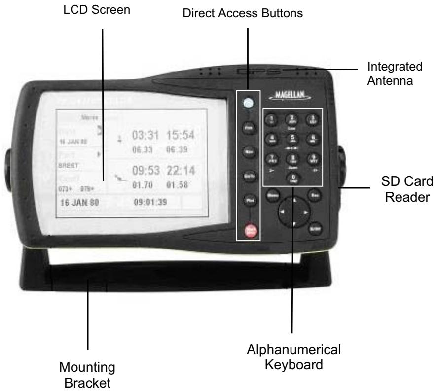
General View of the Device: Front
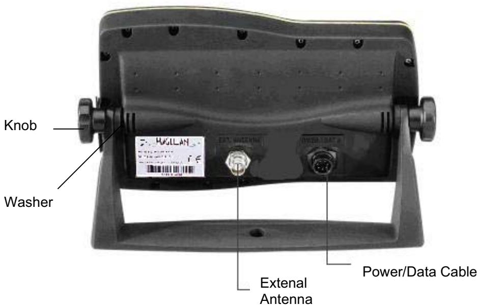
General View of the Device: Back
Power On and Off
Power On
Push the PWR button to turn on your GPS. You will hear a beep and the following screen will appear:

FX324 MAP
V100c SN:—
Copyright 2002 Thales Navigation - All rights reserved
Note: The first time you use your FX324 MAP, an intermediate screen will ask you to select your language. See The First Time You Use Your FX324 MAP.
After a few seconds, the following warning message will appear:
WARNING
The electronic marine chart with GPS is a navigation support tool, which must not, under any circumstances, replace the government navigation rules. Official marine charts and Notices To Mariners alone contain all safety information.
Thales Navigation and its dealers shall not be liable for any damage, tangible or intangible, which would result with the use of this equipment.
OK
Push Enter to display the Position screen.

| Speed 9.0K T | Course 075° | CPE 9F T |
Your position is displayed after a few minutes, the time it takes to make the first calculation.
The first time you use your FX324 MAP, you will have to make a certain number of configurations in order for the information to appear in the appropriate format.
See The First Time You Use Your FX324 MAP.
Off
To turn off your GPS, hold down the PWR button for four to five seconds. A countdown appears until the device is turned off.
Table of Buttons and their Functions
| Button | Function | Note |
| PWR | Turns the device on or off and allows you to set the backlighting and contrast (FX324 MAP only). | Hold down the button for 4 to 5 seconds to turn off the device. Push the button briefly to set the contrast and screen backlighting. |
| Pos | Displays the Position screen, which allows you to read essential information pertaining to your position. | Push the button a second time to display the second Position screen. |
| Nav | Displays the Navigation screen, which allows you to view your speed and your course over the ground. | Push the button a second time to display the second Navigation screen. |
| GoTo | Displays the GoTo screen, which directs you toward a waypoint and enables you to follow a route. | Push the button a second time to display the second GoTo screen. |
| Plot | Displays the Plotter screen which enables you to follow your position and your route on the chart. | Push the button a second time to display the second Plotter screen. |
| 0-9 | Keypad that allows you to enter alphanumeric values. | Hold the button down to access the alphabet keypad. For example, holding the 2 button down displays the letters a, b and then c. |
| Z-(7) | In the Plotter function, hold this button down to zoom out. | Also enables you to change the zoom scale in GoTo-3D Road mode. |
| Z+(9) | In the Plotter function, push this button to zoom in. | Also enables you to change the zoom scale in GoTo-3D Road mode. |
| Zoom (8) | In the Plotter function, push this button to select the zoom scale from a list or activate the automatic zoom mode. | |
| →← (5) | In the Plotter function, push this button to choose a waypoint and center it on the screen. | |
| Curs (2) | In the Plotter function, push this button to activate/deactivate the cursor mode. | |
| Menu | Displays the menus that allow you to configure the settings for your device. | If you press Menu while on the Position, Navigation, GoTo or Plotter screens, the corresponding menu automatically appears. |
| Esc | Returns you to the previous screen. | |
| Enter | Allows you to select an action or enter data. | |
| Enables you to browse the screens and menus and to move the cursor on the chart. |
Note: Option 2 in the Setup Menu allows you to activate or deactivate a beep whenever a button is pushed.
Screen Introduction
Navigating through the Screens and Selecting Options
The button lets you navigate intuitively through the various screens and menus. It allows you to move through each area of the screen and to move from one tab to another so that you can select actions or options.
The Esc button will cancel a selection or return you to the previous screen.
Selecting an Option in a Menu
Push the Menu button to access the various menus on your FX324 MAP. Each menu is presented on a tab and the accessible options on each menu are numbered from 1 to 8. Those that can be selected are the ones for which the number background is black (dark blue for the FX324 MAP Color). The icons or the value opposite the number indicate the current settings for that option.
Example: In the Route/Track menu below, Option 5 - Track List can be selected, but not Action 1 - Route List. Option 6 - Home Function is currently inactive and Option 7 - Track Interval is set for every 0.25 units of distance.
| NAV | WPT | RTE/TRK | PLOT |
| 1 | Route List | 5 | Track List |
| 2 | Create Route | 6 | Home Function No |
| 3 | Delete All | 7 | Track Interval 0.25 Dist. Unit |
| 4 | Used Memory 00/30 |
To select an option, you must:
- display the menus by pushing the Menu button.
- select the desired menu by using the and arrows on the button.
-type the number of the option on the alphanumeric keypad.
According to the option you have selected, you can either:
- enter a value using the alphanumeric keypad
- access a scrolling list to select the desired value, or
- access a new screen.
Note: To return to the previous screen, push the Esc button.
Selecting an Action
The actions that can be selected are displayed in black (red or dark blue for the FX324 MAP Color.) To select an action, highlight its icon or its text using the button and push Enter.
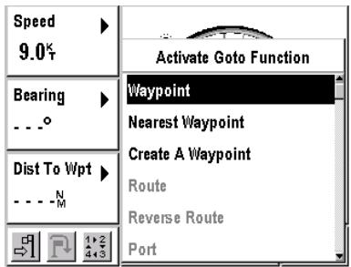
Example: On the GoTo screen below, the action - Activate the GoTo Function can be selected because the icon is in black (red for the FX324 MAP Color), but you cannot select the action - Go to the next waypoint.
Example: On the GoTo screen below, the action Create a Waypoint can be selected, since the text is in black (dark blue for the FX324 MAP Color), but the Route action cannot be selected.
□ Interactive window
Many of the function screen windows display the symbol. This symbol means that the window is not a simple display window, but that it is either:
- a window with configurable settings
- a data entry window
- a selection window, or
- a point of access to another screen.
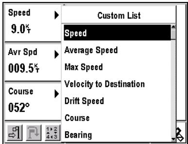
Choosing the Information Displayed in the Configurable Window
The windows for the Position, Navigation, GoTo and Plotter screens that display the symbol are configurable. They have a list from which you can choose the type of information displayed.
Example: On the GoTo screen below, the speed, average speed, and course displays can be replaced by any other information selected from the scrolling list.
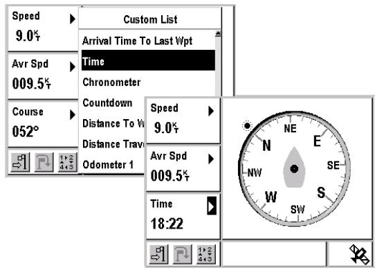
To modify the display in a configurable window, select it using the button and push Enter. Move through the list using to select the type of information to be displayed and then push Enter. The display updates with the new type of information.
Example: In the GoTo screen below, the time is displayed instead of the course.
The configurable windows can display the following information:
| Speed | Your speed over the ground. |
| Average Speed | Your average speed over the ground. |
| Maximum Speed | Your maximum speed over the ground. |
| Velocity to Destination | The speed with which you are approaching your destination waypoint, also known as VMG (Velocity Made Good). |
| Drift Speed | The speed with which your vessel is drifting relative to the destination waypoint. The letter R (Right) or L (Left) indicates the direction your vessel is drifting. |
| Course | The angle formed by the course direction and reference north. Your course over the ground is constantly updated. |
| Bearing | Angle, in degrees, between your current position and the position of the destination waypoint. This is the course to steer to reach the destination waypoint. |
| Course Correction | The correction to be made to the course in order to navigate to the destination waypoint. The letter R (Right) or L (Left) indicates the direction of the course correction to be made. |
| Time to Go | Estimated amount of time it will take to reach the destination waypoint. |
| Time to Go to Last Waypoint | Estimated amount of time it will take to reach the last waypoint on the active route. |
| Trip Time | Length of time traveling since the last time the counter was reset to zero. |
| Arrival Time | Estimated time at which the vessel is expected to reach your destination waypoint. |
| Arrival Time to Last Waypoint | Estimated time at which the vessel is expected to reach the last waypoint on the active route. |
| Time | Local Time. |
| Chronometer | Displays the chronometer. |
| Countdown | Displays the countdown. |
| Distance to Waypoint | Distance to travel to reach the destination waypoint. |
| Distance to Last Waypoint | Distance to travel to reach the last waypoint on the active route. |
| Distance Traveled | Distance the vessel has already traveled. |
| Odometer 1 | Distance counter 1. |
| Odometer 2 | Distance counter 2. |
| XTE | Acronym for Cross (X) Track Error. Indicates the distance between the vessel's current position and the direct line between your starting point and your destination waypoint. The letter R (Right) or L (Left) indicates whether your vessel is to the right or left of the direct line between your starting position and your destination waypoint. |
| CPE | Acronym for Circle of Probable Error. Indicates the radius of the circle containing 50% of the positions calculated by your GPS. |
| Altitude | Your altitude. |
| Water Level | Height of the water at the selected port. |
| Battery Voltage | The voltage of the battery to which the GPS is connected. |
Note: When you select a type of data to display this selection applies only to the currently displayed screen. Example: the setting for the configurable window on Position Screen 1 is independent from the setting for the configurable window on Navigation Screen 1.
Setting the Local Time or a Date (tide or current calculation)
The Date and Time windows that display the symbol allow you to enter a new value.
The hours, minutes, days and years are entered in European format (dd/mm/yy) using the alphanumeric keypad, and the months are selected with the and arrows on the button.
The and arrows on the button allow you to move from one field to another.
You must push the Enter button to enter a new time or date.
Example: Push Enter in a Date window. The window is displayed in gray (light blue for the FX324 MAP Color) and the cursor is positioned to allow you to enter a new date.
Type the day with the alphanumeric keypad.
Select the month using the and arrows on the button.
Go to the Year field using the arrow on the button.
Type the year using the alphanumeric keypad.
Enter the date by pushing Enter.
Select a value from the list.
The windows that display the symbol allow you to select a value from a list or a hierarchy of lists.
Example: Push Enter in the Port window (Pos Pos TIDE Tab). In each of the lists that are displayed successively, highlight the desired value and push Enter.
Accessing Another Screen
In some windows, the symbol indicates a point of access to another screen.
Example: Select the Countdown window from the second Navigation screen (Nav Nav Countdown Enter). An extra screen is displayed to enable you to configure and begin a countdown.

Note: To return to the previous screen, push the Esc button.
Table of Main Action Icons and their Functions
Most of the actions are symbolized by icons. To select an action, highlight its icon using the button and push Enter.
Note: An action for which the icon is displayed in black can be selected (red for the FX324 MAP Color); an action for which the icon is displayed in gray (light blue for the FX324 MAP Color) cannot be selected.
| Action Icon | Function | Note |
| Save | ||
| Display the List | Displays lists of waypoints or routes | |
| Edit | Allows you to edit a waypoint or a route | |
| Delete or Reset | ||
| Activate the GoTo Waypoint or GoTo Route function | Also symbolizes the Arrival Alarm in the Navigation menu | |
| Go to the next waypoint in the active route | ||
| Deactivate the GoTo function or stop the countdown | ||
| 1,2 4+3 | Change the display mode on the GoTo screen | Push Enter several times to display the 4 modes successively: Compass, 3D Road, Radar and Data |
| ← | Reverse a route | |
| ∃■ | Add a waypoint to the end of a route | |
| ∃■ | Insert a waypoint into a route | |
| ∃ | Delete a waypoint from a route | |
| → | Convert a Track into a Route | |
| ◎ | Make a track visible on the Plotter screen | |
| ▲ | Move up in a list | Select this icon and push Enter to move up one row in a list |
| ▼ | Move down in a list | Select this icon and push Enter to move down one row in a list |
| ⊥ | Anchor Alarm | This alarm is automatically activated and is always highlighted on the Navigation menu |
| ∥ | Cross Track Error Alarm | Is highlighted on the Navigation menu when the alarm is activated |
| ○ | Speed Alarm | Is highlighted on the Navigation menu when the alarm is activated |
| ∑ | Begin the Countdown | |
| ∑0 | Transfer a file to the SD Card | |
| ∑0 | Transfer a file from the SD Card |
Unit of Measurement Abbreviations Table
Your FX324 MAP lets you select the units of measurement you wish to use. These units of measurement are abbreviated as follows:
| Abbreviation | Unit of Measurement | Note |
| FT | Feet | 0.3048 meters |
| H | Time | |
| KHZ | Kilohertz | |
| KM | Kilometer | |
| KH | Kilometers per hour | |
| MT | Meter | |
| MI | Statute mile | 1609 meters |
| N M | Nautical mile | 1852 meters |
| MH | Statute miles per hour | |
| KT | Knots | 1 Nautical Mile/Hour |
| O | Degrees | |
| GR | Grade | |
| N | North | |
| E | East | |
| W | West | |
| S | South |
Regulating the Screen Contrast and Backlighting
Your FX324 MAP allows you to regulate the screen contrast and backlighting.
Push the PWR button briefly to display the following window:
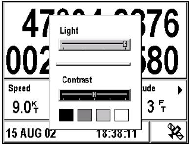
Backlighting
Select the Light setting bar with the and arrows on the button.
Then select the desired level of backlighting with the and arrows on the button. The far left of the bar represents the lowest level of backlighting and the far right represents the highest level.
Note: The optimal display for the FX324 MAP Color is reached after a few minutes.
Screen Contrast (this option is not available for the FX324 MAP Color)
Select the Contrast setting bar with the and arrows on the button. Then select the desired level of contrast with the and arrows on the button. The far left of the bar represents the highest level of contrast and the far right represents the lowest level.
Push Esc to return to the previous screen.
3. The First Time You Use Your FX324 MAP
When you use your FX324 MAP for the first time, you will have to make a few configuration choices and enter some necessary information so that your GPS displays the information in the appropriate format.
Choosing the Display Language
The first time you use your FX324 MAP, the following window appears, allowing you to select your display language.
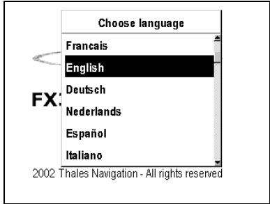
Browse the scrolling list with the button and select the desired language by pushing Enter.
You can change the language in which the information is displayed at any time.
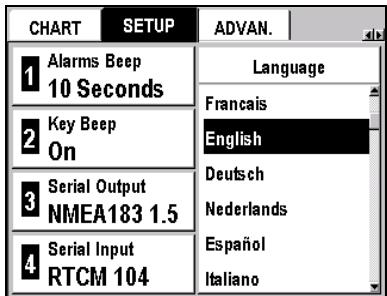
Menu SETUP Tab 6-Language
Select the desired language from the scrolling list and push Enter. The screen of your FX324 MAP will be redisplayed in the selected language.
Note: The language selection has no influence on the units of measurement used, nor on any other parameter.
Setting the Local Time
Your FX324 MAP uses UTC time, which is automatically and constantly updated by the satellites from which it is receiving signals. You need to set the local time if you are in a time zone other than the UTC time zone.
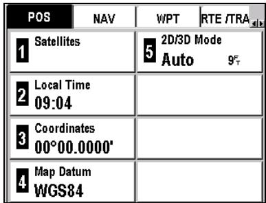
Menu POS Tab 2-Local Time
| POS | NAV | WPT | RTE /TRA |
| 1 Satellites | 2D/3D Mode | ||
| 5 Auto | 9° | ||
| Local Time 18:47 | |||
| 3 Coordinates 00°00.0000° | |||
| 4 Map Datum WGS84 | |||
Enter the local time with the alphanumeric keypad and push Enter.
See Setting the Local Time or a Date.
Note: The local time must be entered in 24-hour format.
Choosing the Units of Measurement
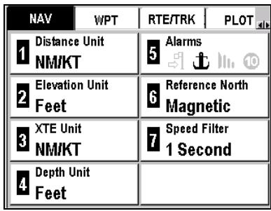
The Navigation menu enables you to select the units of measurement that are used in displaying the information you need to navigate:
- unit of distance and speed
- unit of elevation (altitude)
- unit of cross track error
- unit of depth
See Unit of Measurement Abbreviations Table.
Note: For each of these units, the current setting is displayed.
| POS | NAV | WPT | RTE /TRA |
| 1 | Distance Unit NM/KT | 5 | Alarms |
| 2 | Elevation Unit Feet | 6 | Reference North Magnetic |
| 3 | XTE Unit NM/KT | 7 | Speed Filter 1 Second |
| 4 | Depth Unit Feet |
Unit of Distance and Speed
In order to change the unit of measurement for distance and speed:
Menu NAV Tab 1-Distance Unit
The available units of measurement include:
KM/KMH Kilometers and kilometers per hour
NM/KT Nautical miles and knots
MI/MPH Statute miles and statute miles per hour
Select a unit from the list and push Enter.
Elevation unit
To change the unit of measurement for the elevation:
Menu NAV Tab 2-Elevation Unit
The available units of measurement include:
Meter
Feet Feet (0.3048 Meter)
Select a unit from the list and push Enter.
Cross Track Error (XTE) Unit
To change the unit of measurement for the cross track error:
Menu NAV Tab 3-XTE Unit
The available units of measurement include:
KM Kilometer
NM Nautical Mile
MI Statute mile
Select a unit from the list and push Enter.
Unit of Depth
To change the unit of measurement for the depth of water in the ports and on the charts:
Menu NAV Tab 4-Depth Unit
The available units of measurement include:
Meter
Feet Feet (0.3048 Meter)
Select a unit from the list and push Enter.
Choosing the Type of Geographic Coordinates
You can select the system of coordinates used to display your position.
Menu POS Tab 3-Coordinates
The available systems of coordinates include:
00°00.000' Latitude and longitude in thousandths of a minute
00'00.0000' Latitude and longitude in ten thousandths of a minute
00°00'00.0" Latitude and longitude in seconds
00.0000GRD Position in grades
UTM Position in UTM
Lamberts Position in Lambert 1
British G. Position in British Grid
Irish G. Position in Irish Grid
Swiss G. Position in Swiss Grid
German G. Position in German Grid
Swedish G. Position in Swedish Grid
Finnish G. Position in Finnish grid
USER User Format
Select a system of coordinates from the list and push Enter.
Note: You can create your own user format. See Choosing the Type of Geographic Coordinates in Position Menu.
Choosing the Map Datum
You can select the format corresponding to the chart you are using.
Menu POS Tab 4-Map Datum
Use this function to make sure the position you report on your paper chart matches the position displayed by your GPS.
Select a map datum from the list of 76 formats and push Enter. If you are not sure which format to use, select the format WGS84.
Note: You can also create your own user format. See Choosing the Map Datum in Position Menu.
Restoring the Default Configuration
At any time you can restore your FX324 MAP default parameters and settings.
To restore your FX324 MAP settings as they were when you used it for the first time.
Menu SETUP Tab 7 Default configuration
Select Yes and push Enter to accept the warning message and restore the default configuration or select No and push Enter to cancel.
4. Reading Your Position
The two Position screens display all the essential information concerning your current position.
Note: If you are using your GPS for the first time, see Using your FX324 MAP for the First Time.
Position Screen No. 1
This screen can be displayed at any time by pushing the Pos button once or twice. It displays the main information concerning your position, your course and your speed.
Example: The screen below displays your position in the chosen system of coordinates, your speed, your course over the ground, your CPE, the date and the local time. The satellite symbol means that your position has been entered and calculated. The symbol indicates a configurable window.
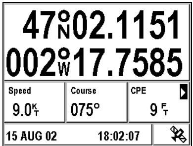
Note: If the screen that is displayed after pushing the Pos button is different, push the Pos button again.
Coordinates
The coordinates displayed are constantly updated. They are displayed in the selected coordinate system.
See Position Menu to change the coordinate system.
A warning message is displayed when your GPS cannot fix your position. It indicates the last position known and the time it was calculated.
Speed
Your speed over the ground is displayed in the selected unit of measurement. Dashes are displayed when your position has not been calculated.
See Navigation Menu to change the units and set the speed filter.
Course
Your course over the ground, relative to the Reference North selected, is expressed in degrees. It is constantly updated and can only be calculated when you are moving. Dashes are displayed when you are not moving.
- Configurable Window
The information displayed in this window can be modified.
Select the window using the button and push Enter. A list of available data is displayed. Select the type of data desired, and push Enter. Your screen is updated.
See Choosing the Information Displayed in the Configurable Window.
Date and Time + Satellite Symbol + WAAS/EGNOS/MSAS Symbol
The date and local time are always displayed. The satellite symbol means that your FX324 MAP has calculated your position.
Note: You can view the satellites used to calculate your position at any time. See Position Menu.
The W symbol is displayed when your GPS is functioning in WAAS/EGNOS/MSAS mode. The S symbol is displayed when your GPS is functioning in simulator mode. The D symbol is displayed when your GPS is functioning in differential mode.
Position Screen No. 2
This screen has four tabs. Ephemeris, Tide, Current and HDR. It can be displayed at any time by pushing the Pos button once or twice.
Note: This screen is always displayed on the last viewed tab.
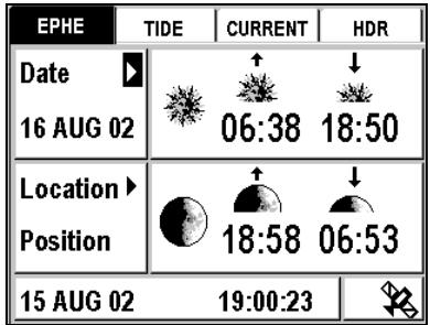
Ephemeris Tab
This tab displays the sunrise and sunset, moonrise and moonset times for a selected date and location.
Example: The following screen displays the sunrise and sunset, moonrise and moonset times for 16 August 2002 at your current position.
Selecting Another Date
Position EPHE Tab Date Enter
Enter the desired date and then push Enter.
See Setting the Local Time or a Date.
Selecting Another Location
Position EPHE Tab Location Enter
Select your current position, a waypoint from your list or a port on the loaded chart.
See Selecting a value from a list and MapSend BlueNav Charts.
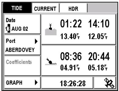
Tide Tab
This tab displays the times for high and low tides, the water height and the coefficients for a selected date and port (coefficients are available only for French internal ports). The displayed water heights are the ones above the height of water at Lowest Astronomical Tide. Please note, these values are provided as a rough guide and may vary with weather conditions.
Example: The screen below displays the tide times, the coefficients and the water heights for 16 August 2002 in the port of Dieppe. At 12.50 pm (time of low tide) the height of water in the port is 06.51 feet above height of water at Lowest Astronomical Tide.
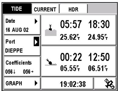
Note: The water heights are expressed in the selected unit of measurement. See Navigation Menu to change the unit of measurement.
Selecting a Date
Position TIDE Tab Date Enter
Enter the desired date and then push Enter.
See Setting the Local Time or a Date.
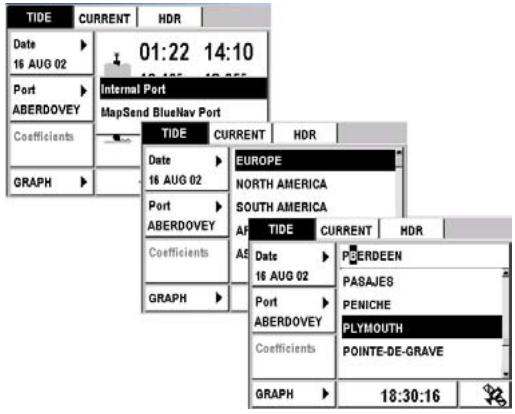
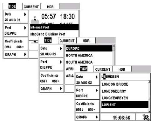
Selecting a Port
Position TIDE Tab Port Enter
Select Internal to choose a port from among the list of 896 worldwide ports in the memory of your FX324 MAP or select MapSend BlueNav Port to choose a port from the loaded chart.
See Selecting a value from a list and MapSend BlueNav Charts.
The time display for the high tide and low tide, the water height and the coefficients are updated according to the date entered and the port selected.
Example: From the TIDE tab on the second Position screen, you can display the tide times and the water heights at the port of Lorient on 20 August 2002.
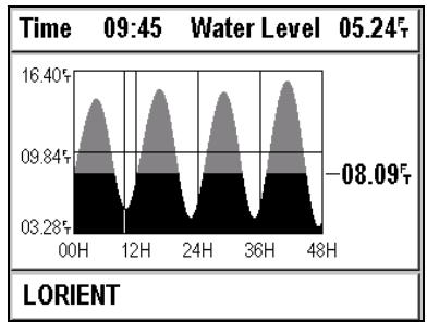
Graph Function
The Graph function allows you to display a graph of water heights for the next 48 hours in the port and at the date that you previously selected. The displayed water heights are the ones above the height of water at Lowest Astronomical Tide.
Position TIDE Tab GRAPH Enter
Example: On the following screen, the water height at the port of Lorient on 20 August 2002 at 9:45 a.m is 5.24 feet above the height of water at Lowest Astronomical Tide.
Use the and arrows on the to view the water height in fifteen-minute intervals over a 48-hour period.
Use the and arrows on the to set the draft for your vessel.
Warning: Please note, these values are provided as a rough guide and may vary with weather conditions.
Current Tab
This tab displays the time of the maximum current, its speed, its angle (i.e. its direction) and the time of the slack water, for a date and station selected from the loaded chart.
The symbol indicates the maximum current of the rising tide.
The symbol indicates the maximum current of the falling tide.
The symbol indicates the time of the slack water before inversion of the current.
Example: At the Saint Georges Channel station on 15 August 2002, the maximum current of the rising tide will occur at 7:02 a.m. and 7:36 p.m. It's speed will be 2 knots and its angle (i.e. its direction with regard to True North) will be 197 degrees. The maximum current of the falling tide will occur at 12:36 a.m. and 1:02 p.m., its speed will be 1.99 knots and its angle will be 14 degrees. The times of the slack water before inversion of the current are displayed in the last column.
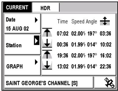
Note: The speed of the current is always expressed in knots.
Selecting Another Date
Position CURRENT Tab Date Enter
Enter the desired date and then push Enter.
See Setting the Local Time or a Date.
Selecting Another Station
Position CURRENT Tab Station Enter
Select a station from the loaded chart and push Enter.
See Selecting a value from a list and MapSend BlueNav Charts.
Graph Function
Select Graph to display a graphical representation of the current for a selected date and station.
Position CURRENT Tab GRAPH Enter
Example: At 8:15 p.m., the current of the rising tide will have a speed of 00.51 knots and an angle (i.e. a direction) of 249 degrees.
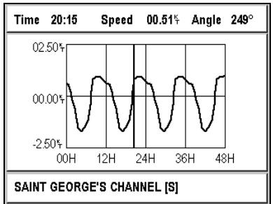
The upper part of the graph represents the current of the rising tide. The lower part of the graph represents the current of the falling tide. The line through the center at 00.00 KT represents the slack water. Each peak represents the maximum current. Use the and arrows on the to move the vertical line, and read the information on the bar at the top concerning the speed and angle of the current, which is updated every 15 minutes.
HDR Tab (True Heading Repeater)
You can connect your FX324 MAP to a true heading sensor such as the 3011 GPS Compass from Thales Navigation. If you have connected your GPS to a compass, the HDR tab will display the following information. The HDR tab is accessed from the second Position screen.
- True Heading (True Head.)
- Rotation Speed (ROT)
- Transversal Speed (TGS)
- Longitudinal Speed (LGS)
- Pitch
- Speed
- Course
- Number of Visible Satellites (Number of Sat)
- Position
Note: See the usage guide for your true heading sensor for all information regarding this connection. If you connect an 3011 GPS Compass, please pay particular attention to the section entitled "Connections to the MLR FX312 and the FX412 PRO" Diagrams and instructions for connecting your FX324 MAP will be identical.
Position Menu
The Position menu can be displayed directly by pushing Menu from any Position screen or by selecting Menu and then the POS tab.
Five options are available.
See Navigating through the Screens and Selecting Options.
Viewing the Satellites
The Satellite option allows you to view the satellites from which your GPS is receiving signals, as well as the accuracy of the calculated position, at any time.
Menu POS Tab 1-Satellites
Example: The screen below shows that the GPS receives 10 satellites. The CPE is equal to 2 meters and the DOP is equal to 1.5. The two w symbols mean that your GPS is currently receiving two Waas or Egnos satellites. In the example below, the reception quality for satellite 06 is not good enough to be used in the position calculation.
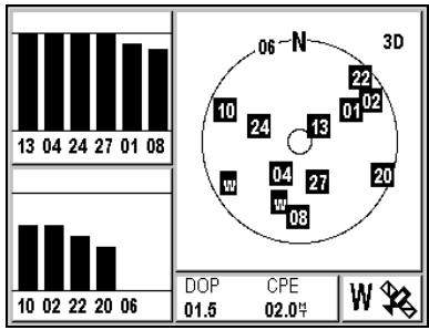
The window to the right of the screen represents the available satellites in the sky. The outer circle represents the horizon and the inner circle
symbolizes the zenith. The closer a satellite is located to the outer circle, the closer it is to the horizon and the more difficult it is to receive its signal. The closer a satellite is located to the inner circle, the higher it is relative to the horizon and the easier it is to receive its signal.
The two windows on the left display the quality of the reception from each satellite. When the bar is completely black, or filled in 3/4 high, the satellite reception is perfect.
Note:
Depending on the time of day, the number of satellites in the sky from a given location usually varies from 6 to 12. On average, 9 satellites are available.
The DOP (Dilution of Position) indicates the accuracy of the position calculation. It depends on the position of the satellites with respect to one another. The closer the DOP is to 1, the better the accuracy.
The CPE (Circle of Probable Error) indicates the radius of the circle containing 50% of the positions calculated by your GPS. For example, if your CPE is 2 meters, your actual position is 50% likely within a radius of 2 meters from the calculated position.
Note:
Because of the position of the satellites (always above), the accuracy of the altitude calculation is approximately half as good as the accuracy for the horizontal calculations.
Setting the Local Time
Your FX324 MAP uses UTC time, which is automatically and constantly updated by the satellites from which it is receiving signals. You need to set the local time if you are in a time zone other than the UTC time zone.
Menu POS Tab 2-Local Time
Enter the local time with the alphanumeric keypad and push Enter.
See Setting the Local Time or a Date.
Note: The local time must be entered in 24-hour format.
Choosing the Type of Geographic Coordinates
The Coordinates option allows you to change the system of coordinates used to display your position.
Menu POS Tab 3-Coordinates
The list of available coordinate systems is displayed.
00°00.000' Latitude and longitude in thousandths of a minute
00'00.0000' Latitude and longitude in ten thousandths of a minute
00.0000GRD Position in grades
UTM Position in UTM
Lamberts Position in Lambert 1
| British G. | Position in British Grid |
| Irish G. | Position in Irish Grid |
| Swiss G. | Position in Swiss Grid |
| German G. | Position in German Grid |
| Swedish G. | Position in Swedish Grid |
| Finnish G. | Position in Finnish grid |
| USER | User Format |
Select a system of coordinates from the list and push Enter.
You can also create your own user format:
Menu POS Tab 3-Coordinates USER Enter
| User Coordinates | |
| Lat Of Origin | Scale Factor |
| 00000000 | 1.00000000 |
| Long Of Origin | Meter Conversion |
| 00000000 | 1.00000000 |
| North Offset | |
| 00000000.0 | |
| East Offset | |
| 00000000.0 | |
For each window, enter the desired value using the alphanumeric keypad and push Enter.
Note: If you hold the 1 button down, you can enter a + or - sign.
Choosing the Map Datum
The Map Datum option allows you to change the format of the chart depending on the paper chart you are using. Use this function to make sure the position you report on your paper chart matches the position displayed by your GPS.
Menu POS Tab 4-Map Datum
Select a map datum from the list of 76 formats and push Enter. If you are not sure which format to use, select the format WGS84.
You can also create your own user format:
Menu POS Tab 4-Map Datum USER Enter
| User Format | |
| Delta X (meters) +0000.0 | Delta F ( x10.000 ) +3.52810665 |
| Delta Y (meters) +0000.0 | |
| Delta Z (meters) +0000.0 | |
| Delta A (meters) +8137.000 | |
For each window, enter the desired value using the alphanumeric keypad and push Enter.
Note: Hold the 1 button down to enter a + or - sign.
□ Choosing 2D or 3D Mode
Your FX324 MAP can calculate your position in two dimensions (latitude and longitude), or in three dimensions (latitude, longitude and altitude).
The 2D/3D Mode option lets you select the mode you wish to use.
Menu POS Tab 5-2D/3D Mode
Select Auto and then push Enter if you want your position to be calculated in 3 dimensions whenever 5 or more satellites are visible.
Select 2D and push Enter if you want your position to always be calculated in two dimensions. The window is redisplayed so that you can enter a fixed altitude. Enter the altitude using the alphanumeric keypad and push Enter.
Select 3D and push Enter if you want your position to always be calculated in three dimensions, even if less than 5 satellites are visible.
Advice: When using the device for boating, choose the 2D mode and enter the elevation of your device with respect to the mean sea level. If you have an external antenna, enter the height of the antenna with respect to the mean sea level.
5. Reading the Navigation Information
The two Navigation screens display all the essential information concerning your navigation: speed and course over the ground, distance traveled, cross track error, etc.
Note: If you are using your GPS for the first time, see Using your FX324
MAP for the First Time.
Navigation Screen No. 1
This screen can be displayed at any time by pushing the Nav button once or twice.
Example: The screen below displays your speed in knots, your course in degrees, two distance counters in nautical miles and your cross track error (XTE) in nautical miles.
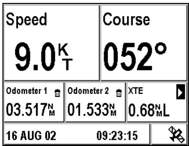
Note: If the screen that is displayed is different after pushing the Nav button, push the Nav button again.
Speed
Your speed over the ground is displayed in the selected unit of measurement.
See Navigation Menu to change the units and set the speed filter.
Course
Your course over the ground is expressed in degrees. The course can only be calculated when you are moving. If you are not moving, dashes are displayed.
- Odometers 1 and 2
The Odometer 1 and Odometer 2 windows display the distance traveled in the selected unit of measurement.
See Navigation Menu to change the unit of measurement.
To reset a counter:
Navigation Counter 1 or Counter 2 Enter
A confirmation message is displayed. Select Yes and push Enter to confirm that you really want to reset the counter or select No and push Enter to cancel.
- Configurable Window
To modify the information that is displayed in this window:
Navigation Window Enter
The list of available information is displayed. Highlight the desired type of information and push Enter. Your screen is updated.
See Choosing the Information Displayed in the Configurable Window.
Date and Time + Satellite Symbol + WAAS/EGNOS/MSAS Symbol
The date and local time are always displayed. The satellite symbol means that your FX324 MAP has calculated your position.
Note: You can view the satellites used to calculate your position at any time. See Position Menu.
The W symbol is displayed when your GPS is functioning in WAAS/EGNOS/MSAS mode. The S symbol is displayed when your GPS is functioning in simulator mode. The D symbol is displayed when your GPS is functioning in differential mode.
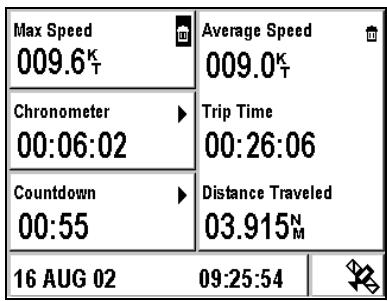
Navigation Screen No. 2
This screen can be displayed at any time by pushing the Nav button once or twice.
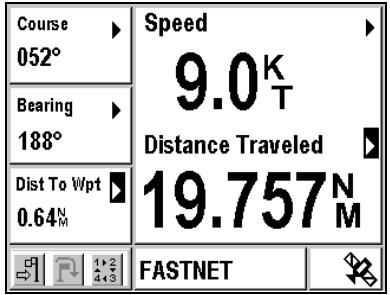
Example: The screen below displays your maximum speed, a chronometer, a countdown, your average speed, the elapsed trip time and the distance traveled.
Note: If the screen that is displayed is different after pushing the Nav button, push the Nav button again.
Maximum Speed
Your maximum speed is displayed in the selected unit of measurement.
See Navigation Menu to change the unit of measurement.
To reset the maximum speed:
Navigation Maximum Speed Enter
A confirmation message is displayed. Select Yes and push Enter to confirm that you want to reset the Maximum Speed to zero or select No and push Enter to cancel.
Chronometer
To start the chronometer:
Navigation Chronometer Enter Start
To stop the chronometer:
Navigation Chronometer Enter Stop
To reset the chronometer:
Navigation Chronometer Enter Rst
- Countdown
To begin a countdown, you must first set the length of time and if necessary, intermediate times, as well as alarms:
Navigation Countdown Enter
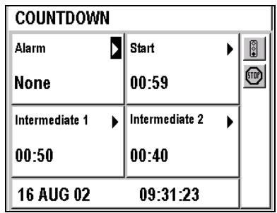
Select Alarm and push Enter to choose the type of alarm that will sound on the intermediate times and at the end of the countdown. Push Enter after selecting the desired alarm type.
Select the Start Time and push Enter to enter the total length of the countdown. Push Enter after entering the length of time.
Select Intermediate 1 and push Enter to enter the countdown length after the intermediate no. 1 time is reached. Push Enter after entering the length of time.
Select Intermediate 2 and push Enter to enter the countdown length after the intermediate no. 2 time is reached. Push Enter after entering the length of time.
Select the icon and push Enter to begin the countdown.
Select the icon and push Enter to stop the countdown.
Average Speed / Trip Time / Distance Traveled
Your average speed is displayed in the selected unit of measurement. It is calculated from the Trip Time and the Distance Traveled displayed below.
See Navigation Menu to change the unit of measurement.
To reset the average speed:
Navigation Average Speed Enter
A confirmation message is displayed. Select Yes and push Enter to confirm that you want to reset the Maximum Speed to zero or select No and push Enter to cancel.
Note: Resetting the Average Speed also automatically resets the Trip Time and Distance Traveled.
Date and Time + Satellite Symbol + WAAS/EGNOS/MSAS Symbol
The date and local time are always displayed. The satellite symbol means that your FX324 MAP has calculated your position.
Note: You can view the satellites used to calculate your position at any time. See Position Menu.
The W symbol is displayed when your GPS is functioning in WAAS/EGNOS/MSAS mode. The S symbol is displayed when your GPS is functioning in simulator mode. The D symbol is displayed when your GPS is functioning in differential mode.
Navigation Menu
The Navigation menu is displayed directly by pushing Menu from any Navigation screen or by selecting Menu and then the NAV Tab.
Seven options are available.
See Navigating through the Screens and Selecting Options.
Choosing Units of Distance and Speed
The Distance Unit option allows you to select the unit of measurement for the distance and the speed.
Menu NAV Tab 1-Distance Unit
The available units of measurement include:
KM/KMH Kilometers and kilometers per hour
NM/KT Nautical miles and knots
MI/MPH Statute miles and statute miles per hour
Select a unit from the list and push Enter.
Choosing the Unit of Elevation
The Elevation Unit option allows you to select the unit of measurement for your altitude.
Menu NAV Tab 2-Elevation Unit
The available units of measurement include:
Meter
Feet Feet (0.3048 Meter)
Select a unit from the list and push Enter.
Choosing the Unit of Cross Track Error (XTE)
The XTE Unit option allows you to select the unit of measurement for the cross track error.
Menu NAV Tab 3-XTE Unit
The available units of measurement include:
KM Kilometer
NM Nautical Mile
MI Statute mile
Select a unit from the list and push Enter.
Choosing the Unit of Depth
To change the unit of measurement for the depth of water in the ports and on the charts:
Menu NAV Tab 4-Depth Unit
The available units of measurement include:
Meter
Feet Feet (0.3048 Meter)
Select a unit from the list and push Enter.
Setting Alarms
The Alarms option allows you to configure and activate or deactivate the various alarms:
Arrival Alarm
Anchor Alarm
Cross Track Error (XTE) Alarm
10 Speed Alarm
Note: The icons for active alarms are displayed in black (dark blue for the FX324 MAP Color) on the Navigation Menu. The icons for inactive alarms are displayed in gray (light blue for the FX324 MAP Color).
To activate/deactivate and configure the various alarms:
Menu NAV Tab 5-Alarms
Example: On the screen below, the Arrival Alarm is set to sound at 1.5 nautical mile from the arrival waypoint.
| Arrival | On | Distance 1.50 N |
| Anchor | On | Distance 0.02 N |
| XTE | Off | Distance 0.00 N |
| IIIa | ||
| Speed | Off | Speed 50.0 T |
For each type of alarm (with exception of the Anchor Alarm that is always active), select the On/Off field using the button and push Enter to select a new status from the list. Then select the Distance or Speed field for setting the alarm, using the button and push Enter to type the desired value using the alphanumeric keypad. Push Enter again to validate the value you entered.
Arrival Alarm
The Arrival Alarm warns you of your arrival at the destination waypoint or of the switch of active waypoint in GoTo Route mode.
See Moving Toward a Waypoint and Following a Route.
The alarm sounds when the distance remaining to be traveled becomes less than the specified value. For example, if you define the arrival alarm to sound at 1 mile, it starts sounding when you approach the waypoint within one mile.
Note: When this occurs, the GPS also automatically moves to the next waypoint in a route. For example, if you define the arrival alarm to sound at 1 mile, waypoint n + 1 becomes active when you approach waypoint n within one mile. See Moving Toward a Waypoint and Following a Route and Automatic Switch to the Next Waypoint in a Route for detailed explanation about the automatic switch to the next destination waypoint in the active route.
The Arrival Alarm is automatically deactivated when the *Anchor waypoint is active.
Anchor Alarm
The anchor alarm warns you that you have drifted from the Anchor waypoint (the position of the anchor). It is automatically activated when Anchor is the active waypoint.
See Activating the Mark function - Anchoring.
The alarm sounds whenever the distance to the *Anchor waypoint becomes greater than the specified value.
Cross Track Error (XTE) Alarm
The Cross Track Error is the distance between the vessel's current position and the direct line between your starting point and your destination waypoint. The alarm sounds whenever your cross track error becomes greater than the specified distance.
Speed Alarm
The speed alarm warns you as soon as your speed becomes less (Min On) or greater (Max On) than the specified value.
Alarms Beep
After setting and activating the alarms, you can select the type of beep that will sound.
The Alarms Beep option on the Setup menu lets you select the type and duration of the alarm beep:
Menu SETUP Tab 1 - Alarms Beep
Select the type of beep from the list and push Enter. If you choose the Continuous option the beep sounds until you press a button.
Defining Reference North
The bearing, the course and the course correction can be referenced with respect to geographic North (true North) or magnetic North
The Reference North option allows you to choose to use true North or magnetic North.
Menu NAV Tab 6-Reference North
Select True or Magnetic and push Enter.
Choosing the Speed Filter
Filtering or smoothing the speed readings makes it possible to have a more stable speed display. For a faster vessel (such as a motorboat), use a short constant, and for a slower boat (such as a sailboat), use a long constant.
The Speed Filter option allows you to select the filter to be applied.
Menu NAV Tab 7- Speed Filter
Select a constant from the list and push Enter.
6. Moving Toward a Waypoint and Following a Route
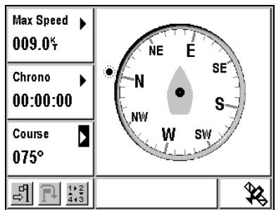
The GoTo screens allow you to navigate toward a waypoint or follow a route. There are four available display modes: Compass, 3D Road, Radar and Data
GoTo Screen No. 1
This screen can be displayed at any time by pushing the GoTo button once or twice. It is made up of an action bar that allows you to activate/deactivate the GoTo function, to advance to the next waypoint in a route, and to choose the display mode you prefer.
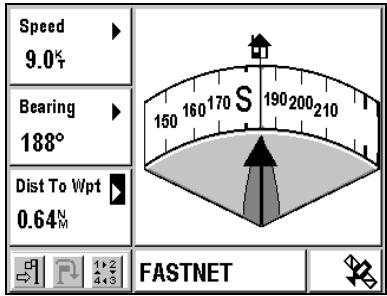
Example: The Compass mode screen below displays the course being followed and the bearing to arrive at the waypoint FASTNET. The three configurable windows on the left of the screen display your speed, the bearing and the distance to waypoint.

Note: If the screen that is displayed after pushing the GoTo button is different, push the GoTo button once again.
Note: This screen is always displayed in the mode that was last used.
Action Bar
The Action Bar displayed at the bottom of the screen allows you to:
Activate/Stop theGoTofunction
F Advancing to the Next Waypoint in a Route
1.2 4.3 Change the display mode
Note: An icon can only be selected if it is displayed in black (red for the FX324 MAP Color).
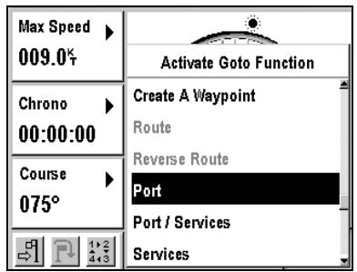
Activating the GoTo Waypoint or Route Function
To activate the GoTo function:
GoTo icon Enter
Select an option from the list and enter your choice by pushing Enter.
The icon automatically replaces the icon as soon as the GoTo mode is activated.
Note: For first time use, the GoTo function will work only after the unit calculated a position fix.
Waypoint
Select this action and push Enter to display the list of all your waypoints.
Choose a waypoint using the button and push Enter to make it your destination waypoint. The name of the selected waypoint is displayed at the bottom of the screen.
Advice: To quickly access a desired waypoint, enter the first letter(s) of its name in the active field. The list is updated with all the waypoint names that begin with that or these letter(s).
Nearest Waypoint
Select this action and push Enter to display the list of 8 waypoints that are closest to your current position. These 8 waypoints are displayed in distance from your current position order.
Choose a waypoint using the button and push Enter to make it your destination waypoint. The name of the selected waypoint is displayed at the bottom of the screen.
Create a Waypoint
Select this action and push Enter to create a new waypoint
See Waypoint Menu.
Route
Select this action and push Enter to display the list of all your routes.
Choose a route using the button and push Enter to make it your active route. The name of the first destination waypoint in the route is displayed at the bottom of the screen.
When activating a route, your FX324 MAP assumes that your current position is at or near the position of the first waypoint in the route (i.e. your vessel is at the beginning of the route). Consequently the first destination waypoint is not the first waypoint in the route but the second one. If your current position at the moment you activate the route is different from the position of the first waypoint and you want to make it mandatory in your journey, you must first do a GoTo Waypoint to the first waypoint in the route and then activate the route once you have reached it.
In the following example, your route is made of three waypoints: A, B and C.
Point X is the current position of your vessel. When activating the route, the destination waypoint is waypoint B and A is considered as your starting point. The dotted line XB is the mobile to waypoint line, AB is the direct line and XZ is your cross track error.
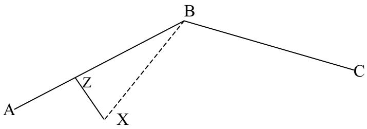
If you want to go through waypoint A, you must do a GoTo waypoint A and then activate the route once you have reached waypoint A.
Note:
In Route mode, the device automatically advances to the next waypoint when the distance to the current destination waypoint becomes less than the distance programmed for the arrival alarm, or when the vessel has passed the line that commands this advance. See Navigation Menu to configure the waypoint arrival alarm and Moving to the Next Waypoint in a Route.
Reverse Route
Select this action and push Enter to active the Reverse Route function and display the list of reversed routes.
Port
Select this action and push Enter to display the list of ports.
Choose a port using the button and push Enter to make this port your destination waypoint. The name of the port is displayed at the bottom of the screen.
Note: The list of ports varies according to the chart that is loaded. See MapSend BlueNav Charts.
Port / Services
Select this action and push Enter to display the list of ports.
Choose a port using the button and push Enter. The list of services that are available at that port is displayed in the form of a bar of icons.
Fuel
Water
Other Services
Repairs
General Services
- First Aid
Information
Select the icon for a type of service using the button to view detailed information.
Note: The list of ports and services varies according to the chart that is loaded. See MapSend BlueNav Charts.
Select and push Enter to make this port your destination waypoint.
Services
Select this action and push Enter to display the list of services.
Port
Fuel
Water
Other Services
Repairs
General Services
- First Aid
Information
Select the icon for a type of service using the button and push Enter to display the list of 8 nearest ports that offer that service. Select one port from the list and push Enter to make this port your destination waypoint.
Note: The list of ports and services varies according to the chart that is loaded. See MapSend BlueNav Charts.
Deactivating the GoTo Function
To deactivate the GoTo function:
GoTo icon Enter
The icon automatically replaces the icon as soon as the GoTo mode is deactivated.
Advancing to the Next Waypoint in a Route
This action allows you to manually advance to the next waypoint. In other words, you can change segments in your route without having to stop the GoTo function.
To advance to the next waypoint in an active route:
GoTo Ricon Enter
The name of the new active waypoint is displayed at the bottom of the screen.
Perform the operation again to advance another waypoint.
Note: In Route mode, the device automatically advances to the next waypoint when the distance to the current destination waypoint becomes less than the distance programmed for the arrival alarm, or when the vessel has passed the line that commands this advance. See Navigation Menu to configure the waypoint arrival alarm and Automatic Switch to the Next Waypoint in a Route.
□ Choosing the display mode: compass, 3D road, radar or data
Select the 14, 23 icon with the button and push Enter to change the display mode. Each time you push Enter, the display mode changes.
Compass Mode
Select the 14, 23 icon with the button and keep pushing Enter until the Compass mode is displayed on the screen.
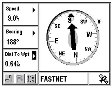
The compass rose turns according to your course and the needle moves according to the bearing to the destination waypoint represented by its icon. To reach your destination waypoint, you must navigate such that the needle remains vertical, pointing to the top of the screen.
The Sun or Moon icon indicates the position of the sun or moon in the sky.
Note: You must always check to make sure there are no obstacles in the direct line between your point of departure and your destination waypoint.
3D Road Mode
Select the 14,23 icon with the button and push Enter until the 3D Road mode is displayed on the screen.
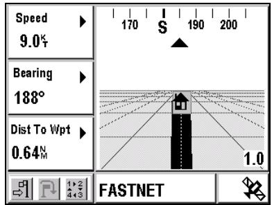
The black line represents the direction to follow to reach the destination waypoint. It pivots according to the difference between your course and the bearing to the destination waypoint. It moves horizontally according to your cross track error (XTE). To reach your destination waypoint, you must navigate such that the line remains in the center, pointing to the top of the screen.
The icon representing the waypoint is displayed when the distance remaining to be traveled (expressed in kilometer) is less than the value of the zoom scale. For example, in the screen above, the waypoint icon is
displayed because the distance remaining is less than 1 kilometer. The destination waypoint icon moves toward the bottom of the screen as you approach it.
Use the Z+ and Z- buttons to change the zoom scale. There are five possible scales:
- 0.25: The length of the road represents a maximum of 0.25 kilometer. The destination waypoint icon is displayed at the end of the road if the distance remaining is less than 0.25 kilometer.
- 0.5: The length of the road represents a maximum of 0.5 kilometer. The destination waypoint icon is displayed at the end of the road if the distance remaining is less than 0.5 kilometer.
- 1: The length of the road represents a maximum of 1 kilometer. The destination waypoint icon is displayed at the end of the road if the distance remaining is less than 1 kilometer.
- 2: The length of the road represents a maximum of 2 kilometers. The destination waypoint icon is displayed at the end of the road if the distance remaining is less than 2 kilometers.
- 4: The length of the road represents a maximum of 4 kilometers. The destination waypoint icon is displayed at the end of the road if the distance remaining is less than 4 kilometers.
Note: You must always check to make sure there are no obstacles in the direct line between your point of departure and your destination waypoint.
When the deviation between your course and the bearing to follow is very big, an arrow appears, indicating the direction in which you should travel.
Radar Mode
Select the 14, 23 icon with the button and push Enter until the Radar mode is displayed on the screen.
The line and the profile at the center of the screen represent your course. The arrow that points toward the destination waypoint icon indicates the
bearing to the destination waypoint. To reach your destination waypoint, you should navigate such that the two coincide.
Note: You must always check to make sure there are no obstacles in the direct line between your point of departure and your destination waypoint.
When the deviation between your course and the bearing to follow is very big, an arrow appears, indicating the direction in which you should travel.
Data Mode
Select the 14, 23 icon with the button and push Enter until the Data mode is displayed on the screen.
In Data mode, all of the displayed information can be configured.
Select any window using the button, push Enter and select the desired type of information from the list. Push Enter to choose your selection.
Configurable Windows
Regardless of the display mode, the three windows on the left of the screen can be configured.
Select any window using the button, push Enter and select the desired type of information from the list. Push Enter to choose your selection.
See Choosing the Information Displayed in the Configurable Window.
Active Waypoint
The name of the active waypoint is displayed at the bottom of the screen. This can be your destination waypoint or the next waypoint in the active route if you are navigating in GoTo Route mode.
GoTo Screen No. 2
This screen can be displayed at any time by pushing the GoTo button once or twice. It indicates the distance and the bearing between two waypoints.
Example: The screen below displays the distance and the bearing between the waypoint Ryde and the waypoint Bognor Regis.
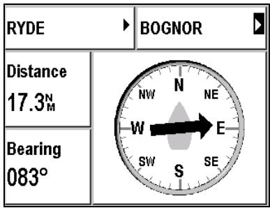
Note: If the screen that is displayed after pushing the GoTo button is different, push the GoTo button once again.
- Waypoint No. 1
Select the upper left window using the button and push Enter to select the first waypoint.
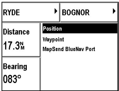
- Select Position to select your current position.
- Select Waypoint to select a waypoint from the list of all your waypoints.
- Select MapSend BlueNav Port to select a port from the chart that is currently loaded in your device.
See MapSend BlueNav Charts.
- Waypoint No. 2
Select the upper right window using the button and push Enter to select the second waypoint.
Select waypoint no. 2 the same way you selected waypoint no. 1.
Note: The two waypoints must not be identical.
Distance
Displays the distance between the two selected waypoints.
Bearing
Displays the bearing from the first waypoint to the second waypoint.
Note: All bearings calculated by your device represent the shortest distance between two points (great circle).
Waypoint Menu
The Waypoint menu can be displayed directly by pushing Menu from any GoTo screen or by selecting Menu and then the WPT Tab.
Five options are available.
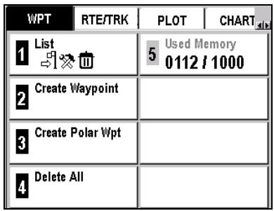
See Navigating through the Screens and Selecting Options.
- Waypoint List
The List option lets you view the list of all your waypoints. Even when no user waypoint has been created the list displays the ANCHOR and MOB waypoints.
Menu WPT Tab 1-List
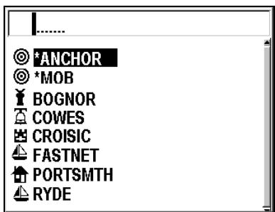
Advice: To quickly access a desired waypoint, enter the first letter(s) of its name in the active field. The list is updated with all the waypoint names that begin with that or these letter(s).
Select a waypoint from the list and push Enter to view its data.
Note: The list of your waypoints can be transferred to or from your SD Card. See Installing an SD Card and Transferring Files.
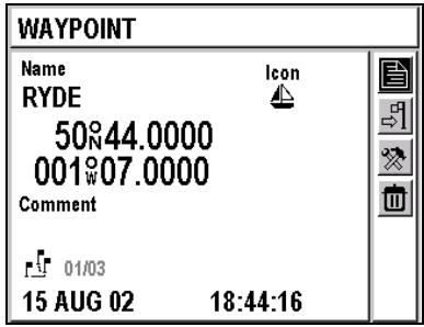
The name of the waypoint, the icon that is associated with it, its coordinates, as well as any comments you may have added (optional) are displayed. The date and time the waypoint was created or modified are displayed for your information at the bottom of the screen.
The icon appears when the waypoint is used in a route. The numbers of all the routes in which the waypoint is included appear opposite the icon.
The action bar displayed on the right of the screen allows you to:

Return to the List of Waypoints

Activate the Waypoint

Modify the Waypoint

Delete the Waypoint
Return to the List of Waypoints
Select with the button and push Enter to display the list of waypoints again.
Activating a Waypoint
Select using the button and push Enter to activate the waypoint.
See Moving Toward a Waypoint and Following a Route.
Modifying a Waypoint
Select using the button and push Enter to display the data for a waypoint and modify the desired fields. The procedure is similar to the one for creating a waypoint.
See Creating a Waypoint.
You must select using the button and push Enter to save the modifications you have made to the waypoint.
The date and the time of the modifications are automatically recorded.
Note: An active waypoint or a waypoint used in a route cannot be amended. This is also true for the ANCHOR and MOB waypoints.
Deleting a Waypoint
Select using the button and push Enter to delete the waypoint. A confirmation message is displayed. Select Yes and push Enter to delete the waypoint or select No and push Enter to return to the menu without deleting it.
Note: An active waypoint or a waypoint used in a route cannot be deleted. This is also true for the ANCHOR and MOB waypoints.
Creating a Waypoint
There are three ways to create a waypoint: from the WPT menu, using the Mark button, or in Cursor mode.
The Create option lets you manually create a new user waypoint.
Menu WPT Tab 2-Create Waypoint
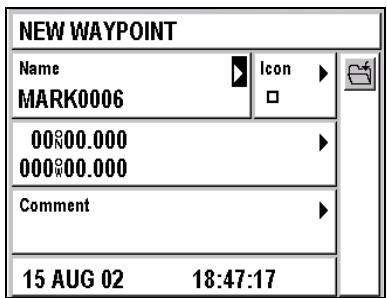
Enter the name of the waypoint
By default, the name of the new waypoint is Mark#### (where ### is an automatically assigned, incremented number). To change the name, select the Name window using the button and push Enter. When amending a letter in the default name, all the subsequent letters are automatically cleared. Enter the name of your waypoint (8 characters maximum) using the alphanumeric keypad and push Enter.
If there is already a waypoint with the same name, when you save it a message asks you to confirm that you want to overwrite it. If the already existing waypoint is active or used in a route, you cannot overwrite it.
Note: To type a letter, hold down the corresponding button. (For example, if you hold the 2 button down, the letters a, b and then c will appear.) Once you have typed the letter or number, the cursor automatically advances to the next space. If you make a mistake, use the and buttons on the to backspace or move the cursor ahead. Use the and buttons on the to return to the previous line or to advance to the next line.
Selecting an Icon
To modify the default icon, select the Icon window using the button and push Enter. Select an icon to assign to your waypoint and enter your choice by pushing Enter.
Entering Coordinates
Select the Coordinates window using the button and push Enter. Enter the coordinates of your new waypoint and push Enter.
See Position Menu to select the system of coordinates.
Note: To choose North or South latitude, use the 6(MNO) button for North and the 7(PR5) button for South. To choose East or West longitude. Use the 3(DEF) button for East and the 9(WXY) button for West.
Entering a Comment
Select the Comment window using the and push Enter. Enter a comment related to your waypoint using the alphanumeric keypad and push Enter.
Recording Your New Waypoint
Once you have entered the information concerning your new waypoint, you must select the 4 icon using the * button and push Enter to save it.
Once your waypoint is saved, it appears in the list of waypoints and can be activated, edited, added to a route, etc.
Note: The date and time it was created are automatically recorded.
Marking a Waypoint with the Mark Button
From any function, you can mark a waypoint (or passage point) by pushing the Mark/MOB button.
See Using the Man Overboard (MOB) and the Mark Functions.
Recording a Waypoint with the Cursor
From the Plotter screen, the Cursor mode allows you to record a waypoint by pointing to its position on the chart and pushing the Enter button.
See Locating Your Position and Course.
Creating a Waypoint Using its Polar Coordinates
You can create a waypoint when you know its distance and its direction from a known position.
The Create Polar Waypoint option allows you to create a waypoint by specifying its distance and its azimuth with respect to your current position or an existing waypoint.
Menu WPT Tab 3-Create Polar Wpt
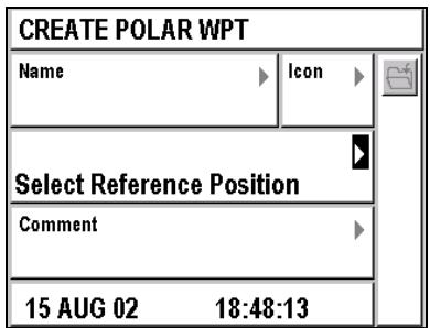
The cursor is automatically positioned in the window, allowing you to choose the reference waypoint.
Push Enter to select a reference position. It can be your current position, a waypoint in your list or a port from the currently loaded chart.
Push Enter again to enter the distance and the azimuth of the new waypoint with respect to the chosen reference waypoint.
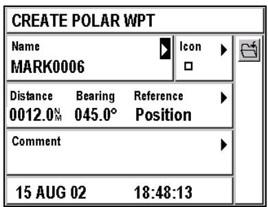
Enter the other information (name, icon, comment) just like you would for a normal waypoint and save your waypoint by selecting + using the and then push Enter.
Example: In the example below, the waypoint MARK0006 is created as being located 12 nautical miles and at 45 degrees from your current position.
□ Deleting All Waypoints
The Delete All option allows you to delete all of your saved waypoints.
Menu WPT Tab 4-Delete All
A confirmation message is displayed. Select Yes and push Enter to delete all waypoints. Select No and push enter to return to the menu without deleting them.
When using this option the *ANCHOR and * MOB waypoints are not deleted but their coordinates are set back to 0.
Note: You cannot select this option when waypoints are used in routes. You must first delete all you routes before you can delete all waypoints.
Checking the Used Waypoint Memory
The 5-Used Memory option displays the number of waypoints in the memory. You can save up to 1000 waypoints in your list. The ANCHOR and MOB waypoints are not accounted, they can be recorded even when the 1000 waypoints maximum capacity is reached.
Note: If you would like to free some of the memory, the list of your waypoints can be transferred to your SD Card. See Transferring Files To and From Your SD Card.
Route and Track Menu
The Route and Track Menu can be displayed by pushing Menu from any screen and selecting the RTE/TRK Tab.
Seven options are available.
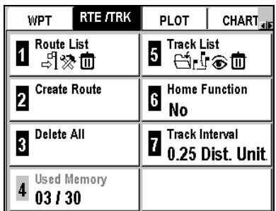
See Navigating through the Screens and Selecting Options.
List of Routes
The Route List option allows you to view the list of all your routes. You cannot select this option if your list of routes is empty.
Menu RTE/TRK Tab 1-Route List
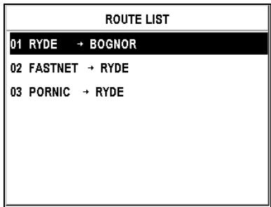
Note: The list of your routes can be transferred to or from your SD Card. See Transferring Files To and From Your SD Card.
Select a route from the list and push Enter to view its data. The list of waypoints that makes up the route is displayed with the distance and the bearing from point to point. The total length of the route is also displayed at the bottom of the screen.
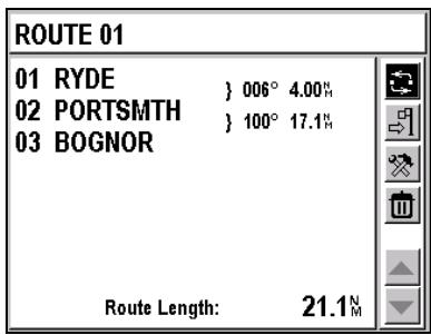
The action bar displayed on the right of the screen allows you to:

Invert the Route

Activate the Route

Modify the Route

Delete the Route
Invert a Route
Select using the button and push Enter to invert the route.
Activate a Route
Select using the button and push Enter to activate the route.
Modify a Route
Select using the button and push Enter to display the data pertaining to the route and change the necessary fields. The procedure is similar to that for creating a route. You must select using the button and push Enter to save the changes you have made.
See Creating a Route.
Delete a Route
Select using the button and push Enter to delete the route. A confirmation message is displayed. Select Yes and push Enter to delete the route or select No and push Enter to return to the menu without deleting it.
If you confirm the route deletion, a message asks you if you wish to delete all the waypoints associated exclusively to this route. Select Yes and push Enter to delete all the waypoints used only in the route you delete, select No and push Enter to delete the route without deleting the waypoints.
Creating a Route
The Create Route option lets you create a new route from the list of your waypoints.
Menu RTE/TRK Tab 2-Create Route
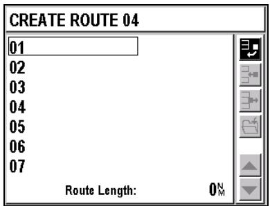
The screen shows an empty list.
Push Enter to display the list of your waypoints.
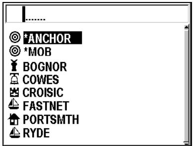
Select the first waypoint in your route and push Enter. The name of the selected waypoint displays at position 01. Push Enter again to select the second waypoint in your route.
Advice: To quickly access a desired waypoint, enter the first letter(s) of its name in the active field. The list is updated with all the waypoint names that begin with that or these letter(s).
Repeat this process until you have entered all the waypoints for your route. A route has a minimum of 2 and a maximum of 50 waypoints.
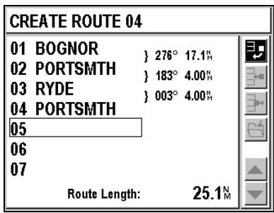
Note: As you enter the waypoints, the bearing and the distance between each are displayed. The total length of your route appears at the bottom right of the screen.
You must select using and then push Enter to save your new route.
The action bar displayed on the right of the screen allows you to:
Add a waypoint to the end of the route
Insert a waypoint between two waypoints of your route
Delete a waypoint from your route
Save your route
Select a waypoint by moving toward the beginning of the route
Select a waypoint by moving toward the end of a route
Select using the button and push Enter to add a new waypoint to the end of your route.
Select using the button and push Enter to insert a new waypoint before the waypoint that you have selected.
Select using the button and push Enter to delete the waypoint you have selected from your route.
Select 2 using the 3 button and push Enter to save your route.
Select using the button and push Enter to select a waypoint while moving toward the top of the list.
Select using the button and push Enter to select a waypoint while moving toward the bottom of the list.
Note: You cannot create a route with a distance of zero.
□ Deleting All Routes
The Delete All option allows you to delete all of your routes.
Menu RTE/TRK Tab 3-Delete All
A confirmation message is displayed. Select Yes and push Enter to delete all of your routes. Select No and push enter to return to the menu without deleting them.
If you confirm the deletion of all routes, a message asks you if you wish to delete all the waypoints associated with the routes. Select Yes and push Enter to delete all the waypoints used in a route or select No and push Enter to delete all the routes without deleting the waypoints.
Checking the Used Route Memory
The 4-Used Memory option displays the number of routes stored in the memory. You can save a maximum of 30 routes in your list.
List of Tracks
The Track List option allows you to view your list of tracks.
Menu RTE/TRK Tab 5-Track List
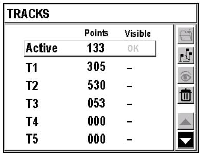
Note: The list of your tracks can be transferred to and from your SD Card. See Transferring Files To and From Your SD Card.
The screen displays:
The active track and the number of points of which it consists. The active track is always visible on the Plotter screen.
A maximum of 5 tracks in the memory with the number of points they include and whether or not these points are visible on the Plotter screen.
The action bar displayed on the right of the screen allows you to:
Save the Active Track in the selected T1 to T5 track
Convert a Track into a Route
Make a track visible or invisible on the Plotter screen
Delete a track
Select a track by moving toward the top of the list
Select a track by moving toward the bottom of the list
Select using and push Enter to save the points in the Active track as the track you have selected, from T1 to T5. The points are added to the existing ones, or they replace them when the 1000-point capacity is exceeded.
Select using and push Enter to convert the selected track into a route of 50 representative waypoints. A message appears to confirm the track has been converted into a route. The message also reads the number of the route created from the track conversion.
Select using and push Enter to activate or deactivate the selected track on the Plotter screen.
See Locating Your Position and Course.
Select using and push Enter to delete the selected track.
Select using and push Enter to select a track by moving toward the top of the list.
Select using and push Enter to select a track by moving toward the bottom of the list.
Example
The following screens show the transferring and saving of the Active Track points into the T2 Track. The T2 Track is then made visible on the Plotter screen.
To select the T2 Track select or with and push Enter until the T2 line is framed.
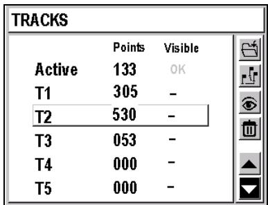
Select with and push Enter to save the Active Track points into the T2 track. All points in the Active Track are transferred to the T2 track and are added to the already existing points.
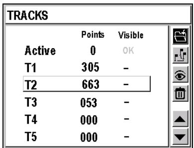
To make the T2 track visible on the Plotter screen, select with and push Enter.
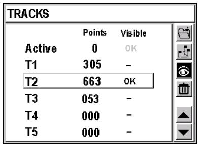
Activating the Home Function
The Home Function option allows you to return to your starting point by following the exact same track, that is, the same route, as you used on your way to your destination.
Menu RTE/TRK Tab 6-Home Function
Select Yes (active) or No (inactive) and push Enter.
Select Yes to automatically create and activate a route enabling you to go back to your starting point following the same itinerary.
Choosing the Track Interval
Option 7 - Track Interval lets you choose the interval at which points in the active track are saved.
Menu RTE/TRK Tab 7-Track Interval
The list that appears offers several different save intervals, defined by time (from 1 to 60 seconds) or by distance (0.01 to 1 units of measurement). Select the desired save interval or select Off and push Enter.
7. Locating Your Position and Course
The Plotter screens represent your course on the chart, allow you to view your current position, your waypoints, the direct route to the active waypoint, etc.
You can load detailed MapSend BlueNav Charts of the zones in which you are navigating at any time.
See MapSend BlueNav Charts.
Plotter Screen No. 1
This screen can be displayed at any time by pushing the Plot button once or twice.
Example: The screen below shows your vessel moving toward the waypoint Wreck. Your vessel is represented by an isosceles triangle whose point corresponds to your course, and your track is represented by a dotted line. The two hachured lines represent the direct line and the mobile to waypoint line.
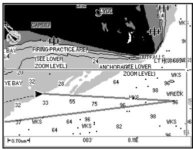
Note: If the screen that appears after you push the Plot button is different, push the Plot button again.
Information Displayed
Your active track is always displayed. The other information displayed depends on the choices you make in the Plot, Chart and Route/Track menus.
See Plotter Menu and Chart Menu to select the display options.
See Route Menu to activate the track display.
Chart
The chart of the segment in which you are navigating is automatically displayed based on your calculated position.
See Chart Menu to select the display options.
When you access the Plotter function, your vessel, symbolized by an isosceles triangle, is located at the center of the screen by default.
Use the button to move around in the chart. Push the Esc button once more to return to the initial mode with your vessel at the center of the screen.
Other Information Displayed
In addition to your vessel and active track, you can also choose to display:
- the North
- the direct line to the active waypoint
- the vessel line to the active waypoint
- the zoom scale
- the active waypoint or all waypoints
- one or several of the 5 saved tracks
- the depth contours and sounding points
- the light sectors
- the navigation aids...
See Plotter Menu and Chart Menu.
Centering the Screen on a Waypoint
You can press the · (5) button on the alphanumeric keypad at any time to display your list of waypoints and select the one you want to display at the center of the chart.
Note: If the selected waypoint is not displayed at the center of the screen, check to make sure that you have not chosen to display only the active waypoint. See Plotter Menu.
Push the Esc button to return to the initial mode with your vessel displayed at the center of the screen.
Note: The function whereby a waypoint is centered on the chart is also available when you are not using a full screen display (Plotter Screen No. 2). Pressing the ← (5) button has no effect when your list of waypoints is empty.
Using the Zoom
Manual Zoom
The Z - (7) and Z+ (9) buttons let you zoom in and out.
Push Z- (7) to zoom out and change to a larger scale to display fewer details.
Push Z^+ (9) to zoom in and change to a smaller scale to view more details.
Note: This function is also available when you are not using a full screen display (Plotter screen No. 2).
Zoom scale and Automatic Zoom
Push the Zoom button (8) to select the zoom scale from the list or activate the Automatic Zoom.
Note: This function is also available when you are not using a full screen display (Plotter screen No. 2).
The available zoom scales include: 4096, 2048, 1024, 512, 256, 128, 64, 32, 16, 8, 4, 2, 1, 1/2, 1/4, 1/8, 1/16, 1/32 and 1/64. Example: If you choose scale 32, the height of the screen will represent a distance of approximately 32 nautical miles.
The Automatic Zoom mode automatically selects the best scale for simultaneously displaying your vessel and your active waypoint.
Note: If the Over zoom mode has not been activated in the Plotter menu, only the zoom scales allowed by the loaded chart are available.
Over zoom
If the Over zoom mode has been activated in the Plotter menu, the OVERZOOM indicator appears when the selected zoom scale makes it impossible to display the chart with a good definition.
If the Over zoom mode has not been activated in the Plotter menu, only the zoom scales allowed by the loaded chart and offering a good definition are available.
See Plotter Menu.
Using the Cursor Mode
From one of the two Plotter screens, push the 2 button on the alphanumeric keypad to activate the Cursor mode.
Use the button to move the cursor on the screen and move around in the chart. The distance and bearing between your vessel and the position of the cursor are displayed at the bottom of the screen.
By moving the cursor around on the chart, you can:
Create a New Waypoint
Move the cursor to pinpoint the required position on the chart and press Enter. Select Mark in the displayed window and push Enter. The waypoint creation screen appears. The cursor's position is automatically recorded as a new waypoint with the name MARK#### (##### being an automatically assigned, incremented number). The time and date are recorded in the comments. If necessary, you can edit the information
(with exception of coordinates) before saving it. Select 2 and push Enter to save the waypoint, which can then be viewed, edited and added to a route like any other waypoint.
See Waypoint Menu.
Create a Route by Saving a Series of Waypoints
Move the cursor to pinpoint on the chart the first waypoint in your route and push Enter. Select Route in the displayed window and push Enter. The cursor's position is automatically saved as the first waypoint in your route. The default name of the waypoint is RWPT#.Push Enter to display the Plotter screen. Move the cursor to pinpoint on the chart the second waypoint for your route and push Enter. The cursor's position is automatically saved as the second waypoint for your route.
Repeat this process until you have entered all the waypoints for your route then select on the route sheet and push Enter to save it.
This route can be activated, edited or deleted as any other route.
See Route and Track Menu
Note: You can view the data for each waypoint in the route but you cannot edit or delete the waypoint. It is not possible to edit or delete a waypoint that is used in a route.
Display Information
Move the cursor to pinpoint an object displayed on the chart ( waypoint, point of interest, navaid) and push Enter. Select Information in the displayed window and push Enter. The list of all the objects you can get information on is displayed. This is the list of all the waypoints, points of interest and navids close to the cursor position. Select one of the object from the list and push Enter to view the information.
Leaving the Cursor Mode
Push the 2 button again to leave the cursor mode and center the screen on the vessel's position.
Deactivating the Chart Display
You can deactivate the chart display and change to simple track mode.
See Chart Menu
Plotter Screen No. 2
This screen can be displayed at any time by pushing the Plot button once or twice.
The main window displays the same chart as in full screen mode and four configurable windows allow you to choose the other information to be displayed.
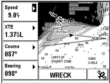
Note: If the screen that appears after you push the Plot button is different, push the Plot button again.
- Configurable Windows
The 4 windows located on the left of the screen can be configured. Select a window and push Enter to choose the type of information you would like to view from the list. Push Enter to choose your selection.
See Choosing the Information Displayed in the Configurable Window.
Plotter Window
The main window displays the same information as in full screen mode.
See Plotter Screen No. 1.
Active Waypoint
The name of the active waypoint is displayed at the bottom of the screen. This can be your destination waypoint or the next waypoint if you are navigating in GoTo Route mode.
See Moving Toward a Waypoint and Following a Route.
Plotter Menu
The Plotter menu can be displayed directly by pushing Menu from any Plotter screen or by selecting Menu and then the PLOT Tab.
Eight options are available.
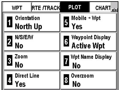
See Navigating through the Screens and Selecting Options.
Choosing the Orientation
The Orientation option allows you to choose the orientation of your Plotter screen.
Menu PLOT Tab 1-Orientation
Select one of the following options and push Enter.
- North up: North is always at the top of the screen.
- Direct Line Up: (sometimes called Course Up) The destination waypoint is always at the top of the screen.
- Course Up: (sometimes called Track Up) The screen is oriented according to the course being followed (the isosceles triangle representing your vessel points to the top of the screen).
Displaying the North
The N/S/E/W option allows you to choose whether or not the indication N (North) is displayed on the Plotter screens.
Menu PLOT Tab 2-N/S/E/W
Select Yes (visible) or No (invisible) and push Enter.
Note: The North shown on the chart is always the True North.
Displaying the Zoom Scale
The Zoom option allows you to choose whether or not the zoom scale is displayed.
Menu PLOT Tab 3-Zoom
Select Yes (visible) or No (invisible) and push Enter.
Displaying the Direct Line
You can choose whether or not to display the direct line between your starting position and the active waypoint. This is the direct line to the waypoint, which is used to calculate the cross track error (XTE). In GoTo mode, the line displayed corresponds to the active segment (that is, the segment between the waypoint you have just passed and the one toward which you are navigating).
The Direct Line option lets you choose whether or not to display the direct line to your destination waypoint.
Menu PLOT Tab 4-Direct Line
Select Yes (visible) or No (invisible) and push Enter.
Displaying the Vessel Line
You can choose whether or not to display the line between your current position and the active waypoint.
Menu PLOT Tab 5-Mobile Wpt
Select Yes (visible) or No (invisible) and push Enter.
Displaying the Waypoints
You can choose to display only the active waypoint or all of the waypoints.
Menu PLOT Tab 6-Waypoint Display
Select Active Waypoint or All Waypoints and push Enter.
Displaying Waypoint Names
You can select one of the options for the waypoints name display.
Menu PLOT Tab 7-Wpt Name Display
Select one of the following options and push Enter.
- No: Only the waypoint icons are displayed.
- First Letter: The first letter of the name of each waypoint is displayed.
- Full: The full name of each waypoint is displayed.
Activating the Over Zoom Mode
When this mode is active, the OVERZOOM indication appears when the selected zoom scale makes it impossible to display the chart with a good definition.
If the Over zoom mode is not active, only the zoom scales allowed by the loaded chart are available.
Menu PLOT Tab 8-Over zoom
Select Yes (active) or No (inactive) and push Enter.
Note: You must be very careful when the OVERZOOM indication is displayed on the Plotter screen since the lack of definition for the chart causes discrepancies with the reality.
8. MapSend BlueNav Charts
Your FX324 MAP is delivered loaded with a chart of the world. Nevertheless, to take full advantage of your GPS, we recommend you load the MapSend BlueNav Charts corresponding to the area in which you are navigating.
Contact your Magellan retailer for a list of all available MapSend BlueNav Charts or visit us at www.magellangps.com.
You can receive a demonstration of the features offered by MapSend BlueNav Charts at any time:
Menu ADVAN. Tab 7-MapSend BlueNav Demo Enter
Chart Menu
The Chart menu can be displayed by pushing Menu from any screen and then selecting the CHART tab.
Seven options are available (eight for the FX324 MAP Color).
| RTE /TRACK PLOT CHART SETUP | |
| Chart Boundaries | Spot Sounding Yes |
| Depth Contour 20m/66ft | Navaids Yes |
| Colored Depth 10m/33ft | Names Yes |
| Light Sectors Yes | |
See Navigating through the Screens and Selecting Options.
□ Choosing the Display Mode for the Chart
You can choose the mode in which the chart is displayed.
Menu CHART Tab 1-Chart
Select one of the following options and push Enter.
- Boundaries: the boundaries are visible on the chart.
- No boundary: the boundaries are not visible on the chart.
- No Chart: the chart is not displayed on the Plotter screens.
Displaying Depth Contours
You can choose how the depth contours are displayed.
Menu CHART Tab 2-Depth Contour
Select the maximum depth for which the depth contours should be displayed and push Enter. For example, select 10 meters/33 feet to display depth contours down to 10 meters/33 feet depth. Select All to display all the depth contours.
Displaying Colored Depth Contours
You can choose how the display varies according to depth.
Menu CHART Tab 3-Colored Depth
Select the depth at which the display color should change and push Enter. For example, select 5 meters/16 feet to change the display color for every 5 meters/16 feet of depth or select None to use the same color for all depths.
Note: The depths are displayed in grayscale on the FX324 MAP and in color on the FX324 MAP Color.
Displaying Light Sectors
You can choose whether or not to display the signal light sectors; that is, whether or not the different lighthouse sectors are visible.
Menu CHART Tab 4-Light Sectors
Select Yes (visible) or No (invisible) and push Enter.
Displaying Sounding Points
You can choose whether or not to display sounding points.
Menu CHART Tab 5-Spot Sounding
Select Yes (visible) or No (invisible) and push Enter.
Displaying Navigation Aids
You can choose whether or not to display navigation aids such as, seamarks, wrecks, buoys and beacons, etc.
Menu CHART Tab 6-Navaids
Select Yes (visible) or No (invisible) and push Enter.
Displaying Names
You can choose whether or not to display names on the chart.
Menu CHART Tab 7-Names
Select Yes (visible) or No (invisible) and push Enter.
□ Selecting the Color Palette
You can choose the color palette used for the display.
Menu CHART Tab 8-Color Palette
Select one of the three palettes and push Enter.
Note: This option is only available on the FX324 MAP Color.
9. Using the Man Overboard (MOB) and the Mark Functions
The Man Overboard (MOB) function allows you to instantaneously mark a position in an emergency situation (such as a person falling overboard), and guides you back to that position as quickly as possible.
The Mark function allows you to save special waypoints (Marks) or passage points as well as your anchoring position.
The Man Overboard and Mark functions can be activated with the Mark/MOB button on your device (red button).
The activation mode for these two functions can be selected in the Setup menu.
- Choose the MOB only mode or the Mark and MOB mode.
MOB Only Mode
When the MOB mode is selected, you only need to push the Mark/MOB button once to activate the Man Overboard function.
The Mark/MOB function allows you to activate the MOB only mode.
Menu SETUP Tab 5-Mark/Mob
Select MOB and push Enter.
Mark and MOB Mode
When the Mark/MOB mode is selected, if you push the Mark/MOB button, it will activate the Mark function. This allows you to select whether the device will automatically record an anchoring position, a Mark, or whether it will activate the Man Overboard function.
The Mark/MOB option allows you to activate the Mark and MOB mode.
Menu SETUP Tab 5-Mark/Mob
Select Mark/MOB and push Enter.
Activating the Mark Function
When the Mark/MOB mode has been selected in the Setup menu, the Mark function can be activated at any time by pushing the Mark/MOB button.
The following window appears:
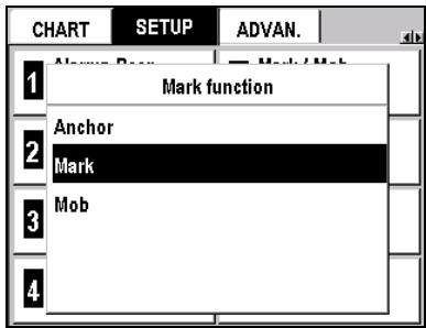
Anchoring
Select Anchor and push Enter to automatically record your current position, as well as the time and the date, in the form of a waypoint called *ANCHOR, which is given an icon that represents a target. This waypoint automatically becomes the active waypoint, and your FX324 MAP displays the GoTo Screen. The Anchor Alarm is automatically activated and the Arrival Alarm is deactivated. The Arrival Alarm remains deactivated as long as the Anchor Alarm is activated.
Note: The ANCHOR waypoint can be viewed but cannot be edited or deleted like other waypoints. It is automatically replaced the next time the Mark/MOB function is used with the Anchoring option. Furthermore, even if your waypoint memory is full, the ANCHOR waypoint can always be recorded.
See Navigation Menu to set an anchor alarm.
Mark
Select Mark and push Enter to display a waypoint data screen.
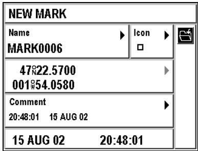
Your current position is automatically recorded as a new waypoint with the name MARK#### being an automatically assigned, incremented number). The time and date are recorded in the comments. If necessary, you can edit the information (with exception of coordinates) before saving
it. Select 2 and push Enter to save the MARK waypoint, which can then be viewed, edited and added to a route like any other waypoint.
See Waypoint Menu.
MOB
Select MOB and push Enter to activate the Man Overboard function.
See below.
Activating the Man Overboard Function
The Man Overboard (MOB) function can be activated at any time by pushing the Mark/MOB button. When the MOB only mode is selected in the Setup menu, a single push of the Mark/MOB button will activate this function. When the Mark/MOB mode has been selected in the Setup menu, the following window will appear after you push the Mark/MOB button.
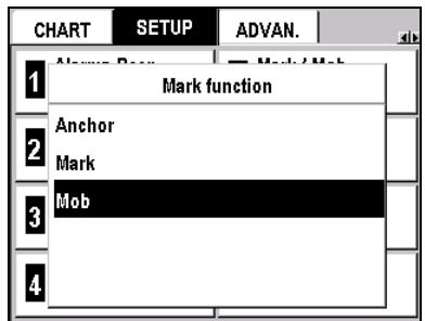
Select MOB and push Enter. Your current position, as well as the time and date, are immediately recorded in the form of a waypoint called *MOB, and the point is assigned an icon representing a target.
The *MOB waypoint becomes the new active waypoint and your FX324 MAP automatically displays the Plotter screen in automatic zoom mode (with the most appropriate scale for simultaneously displaying your vessel and the Man Overboard position).
To stop the Man Overboard function, you must deactivate the *MOB waypoint that was created. To deactivate the GoTo function:
GoTo icon Enter
Note: The MOB waypoint can be viewed but cannot be edited or deleted like other waypoints. It is automatically replaced the next time the MOB function is used. Furthermore, even if your waypoint memory is full, the MOB waypoint can always be recorded.
10. Installing an SD Card and Transferring Files
Installing an SD Card
Your FX324 MAP has an integrated SD Card reader. To install or change the SD Card in your FX324 MAP, you must:
- open the door on the right side of the device by carefully pulling open the lid. If necessary, pull out the card that is already installed by lightly pushing on it until you hear a click and then carefully pulling it out of the reader.
Warning! We recommend you turn off your FX324 MAP when installing or removing a SD Card. Failure to do so may cause dysfunction.
-
insert the new SD Card, with the logo facing you, without forcing it, and push it in until you hear a click.
-
carefully close the door.
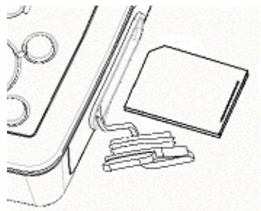
Note:
Make sure you do not let any water get into the slot, and you should also check to be sure that the SD Card you insert is completely dry. The warranty of your device is no longer valid if you use it incorrectly.
Warning!
The IP67 waterproofness standard can be warranted only when the door is properly closed.
Transferring Files To and From Your SD Card
Aside from loading the chart, your SD Card allows you to transfer information to and from your FX324 MAP such as your waypoints and routes lists, your list of tracks and your configuration parameters.
This function is particularly useful when your waypoint or route memory is full. It allows you to free up memory while preserving the information on an external, reusable medium.
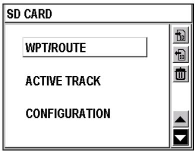
The center window displays the type of information to be transferred.
The action bar on the right of the screen enables you to:
SD transfer files from your FX324 MAP to your SD Card
transfer files from your SD Card to your FX324 MAP
delete files
select the type of file to be transferred.
select the type of file to be transferred.
Select or using and push Enter to select a file type ( waypoint/route, tracks or configuration) by moving up or down through the list.
Select using and push Enter to transfer the selected file from your FX324 MAP to your SD Card.
Select using and push Enter to display the list of files that can be transferred from your SD Card to your FX324 MAP. Select the desired file and push Enter. The file is transferred.
Select using and push Enter to display the list of files that can be deleted. Select the desired file and push Enter. The file is deleted.
11.Using the Navigation Simulator
The navigation simulator is for training purposes. It simulates the position and the movement of your vessel and, as a result, of your GPS. All the navigation functions can be used as they would be if you were really moving.
The Simulator option allows you to configure and activate the navigation simulator.
Menu ADVAN. Tab 3-Simulator
| Simulator | |
| Coordinates | Date |
| 47°06.000 002°07.000 | 16 AUG 02 |
| Speed | Time |
| 009° | 20:49 |
| Course | Simulator |
| 049° | On |
Coordinates
Select this window and push Enter to input a position.
Speed
Select this window and push Enter to input a speed.
Course
Select this window and push Enter to input a course.
Date
Select this window and push Enter to input a date.
Time
Select this window and push Enter to enter to enter the time.
Simulator
Select this window and push Enter. Select On to activate the simulator or select Off to deactivate it. Push Enter to choose your selection.
12. Using your FX324 MAP in Slave Mode
Slave Mode allows you to use your FX324 MAP as a repeater when its NMEA input is connected to the NMEA output of another device (GPS, PC, Navigation System, etc.).
When the slave mode is active, the FX324 MAP uses the waypoints received through its NMEA input to automatically activate its GoTo function while continuing to calculate its position using its antenna.
In order to function in slave mode, the following conditions must be met:
- The slave mode must be active in the FX324 MAP:
Menu ADVAN. Tab 2-Master/Slave Slave Enter
- The FX324 MAP serial input must be programmed in NMEA 183 format:
Menu SETUP Tab 4-Serial Input NMEA 183 Enter
- The FX324 MAP serial input must be directly connected to the NMEA output of the master GPS.
- The master GPS must send the active waypoint through its serial output in BWC sentences (NMEA 183 1.5, 2.0 or 2.3 standard).
See Digital Output and NMEA Digital Input.
If the formats and connections are correct the name of the waypoint received is displayed on the GoTo screen. All the navigation information is then calculated with respect to this waypoint.
The starting position used to calculate the cross track error and the velocity to destination is your current position at the time the FX324 MAP receives the waypoint from the master GPS for the first time.
The position of the waypoint received is recorded in the list of waypoints under the displayed name. Your FX324 MAP will automatically follow and record all of the other waypoints received.
Note: When the slave mode is active, the GoTo function is only active for the waypoint received through the NMEA input. It is no longer possible to activate another waypoint or route.
To return to a normal function mode, you must put the device back into master mode:
Menu ADVAN. Tab 2-Master/Slave Master Enter
13.Using Your FX324 MAP in DGPS Mode
This section describes the use of your FX324 MAP with the differential receiver DF300 MLR or with another type of differential receiver.
Using the FX324 MAP with a DF300 MLR Differential Receiver.
The DF300 is a differential correction receiver from the MLR range, designed to be completely controlled from your FX324 MAP.
- Connecting the DF300 Receiver
Your FX324 MAP has a digital input to which you can connect an external differential receiver. You should follow the following connection table:
| Description FX324 MAP | FX324 MAP Wires | DF300 Receiver Wires |
| 0 volts | Blue | Blue |
| + 10 to 36 volts DC | Red | Red |
| RS422 Reference | Orange | Yellow |
| RS422 Output | Yellow | Green |
| RS232 Reference | Green | Black |
| RS232 Input | Black | White |
□ Configuring the Serial Output Port
In order to control the functioning of the DF300 from your FX324 MAP, the serial output port must be in NMEA 183 1.5 or NMEA 183 2.0 or NMEA 183 2.3 format and the PML2 sentence must be selected for this format.
Menu SETUP Tab 3-Serial Output
Select NMEA 183 1.5 or NMEA 183 2.0 or NMEA 183 2.3 from the list and push Enter.
The following screen appears:
| NMEA Sentences | |
| Sentence 1 | Sentence 5 |
| AAM | GGAM |
| Sentence 2 | Sentence 6 |
| APB | GGAD |
| Sentence 3 | Sentence 7 |
| BWC | GLLC |
| Sentence 4 | Sentence 8 |
| GGAC | GLLM |
Select the Sentence 1 window and push Enter.
Select PML2 from the scrolling list (bottom of the list) and push Enter.
□ Configuring the Serial Input Port
To receive the differential corrections, the Serial Input Port must be set on RTCM104.
Menu SETUP Tab 4-Serial Input RTCM104 Enter
□ Configuring the DF300 from your FX324 MAP
In order to configure the DF300 from your FX324 MAP, the serial output port must be in NMEA 183 1.5 or NMEA 183 2.0 or NMEA 183 2.3 format and the PML3 and MSK sentences must be selected for this format.
Menu SETUP Tab 3-Serial Output
Select NMEA 183 1.5 or NMEA 183 2.0 or NMEA 183 2.3 from the list and push Enter.
Select the Sentence 2 window and push Enter. Select PML3 from the scrolling list and push Enter.
Select the Sentence 3 window and push Enter. Select MSK from the scrolling list and push Enter.
To display the DGPS information screen:
Menu ADVAN. Tab 1-DGPS
| Bauds 100 T. Freq. 300.0 KHZ Signal Level |
| Mode AUTO R. Freq. - - - - - - - - - - - - - - - - - - - - - - - - - - - - - - - - - - - - - - - - - - - - - - - - - - - - - - - - - - - - - - - - - - - - - - - - - - - - - - - - - - - - - - - - - - - - - - - - - - - - |
| Corrected Satellites 02 04 10 13 16 17 18 24 26 28 . . . . . . . . . . . . . . . . . . . . . . . . . . . . . . . . . . . . . . . . . . . . . . . . . . . . . . . . . . . . . . . . . . . . . . . . . . . . . . . . . . . . . . . . . . . . . . . . . . . . . Station : 464 . . . . . . . . . . . . . . . . . . . . . . . . . . . . . . . . . . . . . . . . . . . . . . . . . . . . . . . . . . . . . . . . . . . . . . . . . . . . . . . . . . . . . . . . . . . . . . . . . . .. D |
Bauds
Select this window and push Enter to select the transmission speed for the station to be received (speed transmitted to the DF300)
T Frequency
Select this window and push Enter to select the frequency of the station to be received (frequency transmitted to the DF300).
R Frequency
This window displays the frequency at which the DF300 functions (frequency received from the DF300).
Level
The level of the differential signal reception. A strong signal is indicated by a bar that is filled 3/4 in black.
Percentage of Error
The error rate of the information received. This rate should be at 0% when functioning in DGPS mode.
Corrected Satellites
The list of corrected satellites.
Station
The identification number of the DGPS station.
Note: When the FX324 MAP functions in differential mode, the letter D is displayed in the status bar of the Position and Navigation screens.
Using the FX324 MAP Receiver with Another Type of DGPS Receiver
Connect your FX324 MAP to the DGPS receiver by following the instructions from the previous section. Configure the FX324 MAP serial input in Differential format (RTCM104).
Choose the GPS mode of functioning (see previous section). Refer to the notice for your differential receiver to find out what information is available.
Note: When the FX324 MAP functions in differential mode, the letter D is displayed in the status bar of the Position and Navigation screens.
14. Installation Recommendations
Installing and Connecting the Receiver
Installation
Your FX324 MAP comes with a bracket that lets you easily attach it to a table, a bulkhead or under a shelf. It can also be built into a bulkhead or a table.
Note: For use without an external antenna, be sure to install the FX324 MAP in an open space so that its integrated antenna is in direct view of the satellites. Always make sure there is no obstacle between the integrated antenna and the sky.
Installing your GPS with the bracket
To install your GPS receiver with the bracket:
- Screw down the bracket using the three screws provided.
- Screw the two knobs on the sides of the GPS, placing one rubber washer between the receiver and the knob.
- Connect the Power/Data cable to the back of your receiver.
- Place your receiver into the notches on the arms of the bracket (place the washer between the device and the arm on the bracket).
- Set the desired angle of the device and tighten the two knobs.
To take the GPS receiver out of its bracket:
- Loosen the two knobs on the sides of your receiver.
Pull the receiver so that it comes out of the arms of the bracket. - Disconnect the Power/Data cable and, if necessary, the antenna cable as well.
Building your GPS into a Bulkhead
To build your GPS receiver into a Bulkhead:
- Cut the bulkhead such that the part that sticks out of the back of the FX324 MAP can be built into the bulkhead and so that the two connectors are accessible. Drill holes into the bulkhead in places that correspond to the four screw pitches on the back of the device.
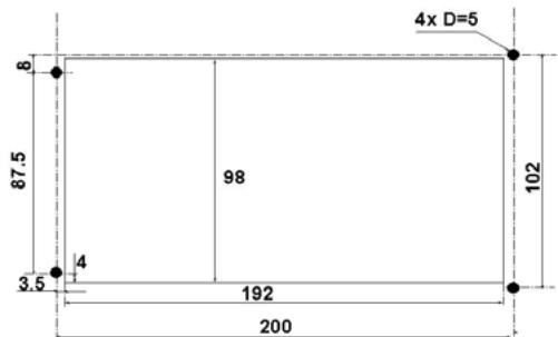
Note: Dimensions are given in millimeters.
Put the receiver into position.
- Screw the four screws into the device, placing a washer and a nut between the bulkhead and the head of each screw.
- When the screws have been screwed in all the way, turn the nut against the bulkhead to firmly attach the device.
- Connect the Power/Data cable to the back of your receiver.
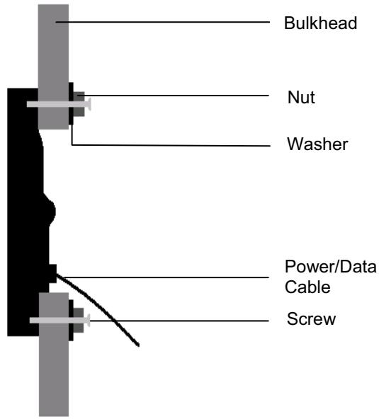
Note:
Your FX324 MAP can also be installed using the optional flush mounting kit. The flush mounting kit must be used only when the GPS is connected to an external antenna. Contact your Magellan distributor for more information.
Connection
| FX324 MAP Description | FX324 MAP Wires |
| Power 10/36 volts | Red |
| Power 0 volt | Blue |
| RS232 Reference | Green |
| RS232 Input | Black |
| RS232 Output | White |
| RS422 Reference | Orange |
| RS422 Output | Yellow |
Power
The Fx324 MAP functions using DC supply of between 10V and 36V. It is protected against current reversal and has a safety fuse. The blue wire must be connected to the - on the onboard power supply and the red wire to the +.
If you need to replace the safety fuse, always use a fuse with the following characteristics: Type: 6.3x32 - Fast blow 2A 250V UL/CSA
Date Output or Digital Output
The FX324 MAP is equipped with two digital outputs:
An RS232 digital output (white wire) and a RS232 Reference (Green wire) for connection to a PC.
An RS422 digital output (yellow wire) and a RS422 Reference (Orange wire) for connection to an autopilot, a radar, a sounding machine, another GPS, etc.
Data Input or Digital Input
The FX324 MAP has an RS232 digital input (black wire) and a RS232 Reference (Green wire) for loading waypoints from a PC and for connecting it to an external differential correction receiver or another GPS.
See Using Your FX324 MAP in DGPS Mode or in Slave Mode.
Connection to a PC
We recommend using the available PC connector.
| Description FX324 MAP | FX324 MAP Wires | PC Pins |
| RS232 Reference | Green | 5 |
| RS232 Input | Black | 3 |
| RS232 Output | White | 2 |
Note: The pin numbers for the PC are the ones for the DB - 9 connector (COM1, COM2, COM3, etc.) available on the PC.
NMEA Connection
Connect the RS422 Reference (orange wire) and the RS422 Output (yellow wire) of the FX324 MAP to the NMEA input on the device to be interfaced (autopilot, route tracker, radar, sounding machine, etc.).
Installing an External Antenna
Your FX324 MAP was designed specifically for use on open hull vessels. However, it can be used inside the cabin if it is connected to an external antenna.
Advice: To preserve the optimal qualities of your FX324 MAP, we insist that it is necessary to use a Magellan brand FX324 MAP-compatible antenna or, if unavailable, an MLR brand ANTGPS15 antenna.
The position of the antenna must be chosen such that the length of the coaxial cable does not exceed 10 meters. The antenna must be placed somewhere where it will be free of any radio interference and in direct view of all points on the horizon:
For sailboats, it is recommended that you install the antenna on the stern rail.
For motorboats, it is recommended that you put the antenna on the cabin. If your boat is equipped with radar, the antenna should be placed so that it overhangs the radar.
The coaxial cable should be connected using the shortest possible path to the receiver and should avoid proximity to any other electrical cables.
The coaxial cable can be cut but its remaining length must be at least one meter.
Note: The tapping in the base of the antenna makes it possible to adapt it to any standard 1 inch x 14 TPI ball joints.
15. Appendices
Glossary of main terms used
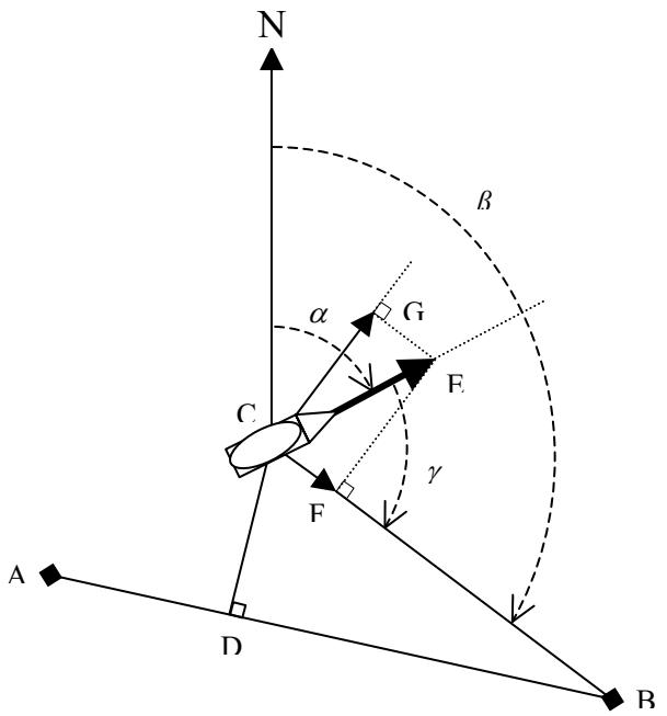
A = Start Point
B = Destination Waypoint
C = Current Position of the Vessel
= Course
= Bearing
= Course Correction
A-B = Direct Line to the Destination Waypoint
C-B = Distance to the Destination Waypoint
C-D = Cross Track Error (XTE)
C-E = Speed
C-F = Velocity to Destination (approach speed to the destination waypoint)
C-G = Drift Speed
| Speed | Speed over the ground. C-E Vector. |
| Average Speed | Average speed calculated based on the speed over the ground. |
| Maximum Speed | Maximum speed over the ground. |
| Velocity to Destination | The speed with which you are approaching your destination waypoint, also known as VMG (Velocity Made Good). C-F Vector. |
| Drift Speed | The speed with which your vessel is drifting relative to the destination waypoint. C-G Vector. The letter R (Right) or L (Left) indicates the direction your vessel is drifting. |
| Course | The angle formed by the course direction and reference North. This angle is referenced with respect to magnetic or true north depending on the reference north chosen. Angle α. |
| Bearing | Angle, in degrees, between your current position and the position of the destination waypoint. This angle is referenced with respect to magnetic or true north depending on the reference north chosen. Angle β. |
| Course Correction | The correction to be made to the course in order to navigate to the destination waypoint. Angle γ. The letter R (Right) or L (Left) indicates the direction of the course correction to be made. |
| Time to Go | Estimated amount of time it will take to reach the destination waypoint. |
| Time to Go Last Waypoint | Estimated amount of time it will take to reach the last waypoint on the active route. |
| Trip Time | Length of time traveling since the last time the counter was reset to zero. |
| Arrival Time | Estimated time at which the vessel is expected to reach your destination waypoint. |
| Arrival Time to Last Waypoint | Estimated time at which the vessel is expected to reach the last waypoint on the active route. |
| UTC Time | Universal Time. |
| Local Time | Universal Time +/- time difference for the time zone in which you are located. |
| Distance to Waypoint | Distance to travel to reach the destination waypoint. C-B Segment. |
| Distance to Last Waypoint | Distance to travel to reach the last waypoint on the active route. |
| Distance Traveled | Distance the vessel has already traveled. |
| Cross Track Error (XTE) | Acronym for Cross (X) Track Error. Indicates the distance between the vessel's current position and the direct line between your starting point and your destination waypoint. The letter R (Right) or L (Left) indicates whether your vessel is to the right or left of the direct line between your starting position and your destination waypoint. C-D Segment. |
| CPE | Acronym for Circle of Probable Error. Indicates the radius of the circle containing 50% of the positions calculated by your GPS. For example, if your CPE is 5 meters, your actual position is within a radius of 5 meters from the calculated position. |
| Coordinates | Unique alphanumeric description of your position on the globe. |
| Map datum | Theoretical mathematical model representing the surface of the earth. The format of the chart that you are using is indicated in the legend. If you are not sure of which map datum to use, select the WGS84 format. |
| NMEA | Acronym for the National Marine Electronic Association, a professional organization that defines the standard serial formats used for interfacing electronic devices for maritime navigation with one another or with computers. |
| WAAS/EGNOS/MSAS | The WAAS, EGNOS and MSAS systems improve the standard civilian GPS signal in order to obtain higher precision in calculating positions. Errors are calculated based on several ground stations and error corrections are transmitted to WAAS/EGNOS/MSAS satellites. These corrections are then transmitted to your GPS receiver, which interprets them. These systems are currently being developed, and depending on your position, may or may not be available. |
Automatic Switch to the Next Waypoint in a Route
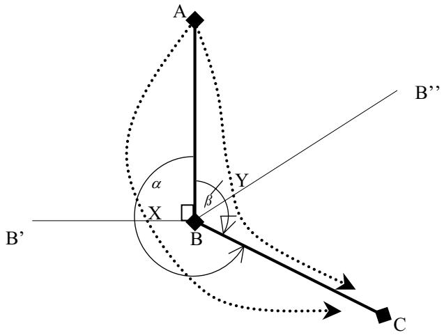
A route is made up of a minimum of three points. The start point A, the first destination waypoint B and the second destination waypoint C.
When following a route from A to B then C, C automatically becomes the active waypoint when B is reached or passed.
AB and BC segments make 2 angles: one is greater than 180^ (angle ) and the other is smaller than 180^ (angle ).
The change of active waypoint occurs differently depending on the angle the vessel is moving in.
Vessel moving in the angle greater than 180^ (angle ):
The change of active waypoint occurs when the vessel crosses the BB' line (X point) where the BB' line is the perpendicular line to the AB segment.
Vessel moving in the angle smaller than 180^ (angle ):
The change of active waypoint occurs when the vessel crosses the BB" line (Y point) where the BB" line is the bisecting line to the angle made by the AB and BC segments.
Arrival Alarm
The change of active waypoint also occurs when the distance remaining between the vessel and the destination waypoint is less than the distance set for the arrival alarm. Example: If the arrival alarm is set to 1 nautical mile, C becomes the new destination waypoint as soon as the vessel enters the circle of 1 nautical mile radius around point B.
Version and Serial Number
You can view the serial number for your device and the version of the software it uses:
Menu ADVAN.Tab 5-Version
Note: This information may be requested when you contact our customer support center.
Digital Output and NMEA Digital Input
Simple NMEA 180 format (for autopilot)
8 bits of DATA, bit D7 = 0, bit D6 = 01 STOP bit, 1200 BAUDS, even parity, 4 sec frequency.
The message includes a single byte where D0 to D5 indicate the cross track error in nautical miles.
Example:
| D7 | D6 | D5 | D4 | D3 | D2 | D1 | D0 | |
| 0 | 1 | 1 | 1 | 1 | 1 | 1 | 1 | - Maximum cross track error to the port side |
| 0 | 1 | 1 | 0 | 0 | 0 | 0 | 0 | - On course |
| 0 | 1 | 0 | 0 | 0 | 0 | 0 | 0 | - Maximum cross track error to the starboard side |
The simple NMEA 180 and complex NMEA 180 data are transmitted successively.
COMPLEX NMEA 182 or NMEA 180
8 bits of DATA, bit D7 = 1, 1 STOP bit, 1200 BAUDS, even parity, 4 sec frequency.
The characters of the message are ASCII characters with D7 = 1
$ MPN X.XX X T XXX XX DXX.XX, X XXXDXX.XX, XnilETX
Beginning XTE Azimuth in° Latitude Longitude End of Block
| L = Port | S = South | E = East |
| R = Starboard | N = North | W = West |
X = ASCII character
NMEA183
8 bits of DATA, 2 STOP bits, no parity, 4800 BAUDS.
NMEA 183 format is a series of several blocks made up of ASCII characters. When the GPS does not calculate the data (no reception), the blocks are nil (empty). Three versions of the NMEA 183 standard are available on the FX324 MAP: Version 1.5, Version 2.0 and Version 2.3.
Note: To use the device with the cockpit repeater Echonav, select the sentences preceded by the letter E (e.g. EGGA).
AAM: Waypoint Arrival Alarm
Version 1.5
\$GPAAM, A/V, A/V, X.X, N, C- -C
Version 2.0 and Version 2.3
$GPAAM, A/V, A/V, X.X, N, C- -C * hh
A/V: Arrival circle entered: Yes = A; No = V
A/V: Perpendicular passed at waypoint: Yes = A; No = V
X.X, N: Arrival circle Radius in NM
Version 1.5:
C--C:Waypoint identification in 4 letters
Version 2.0 and Version 2.3:
C--C:Waypoint identification in 6 letters
*hh: Sentence checksum
APB: Autopilot format B
Version 1.5
$GPAPB, A/V, A/V, 0.05,R,N, A/V, A/V, 000,M,C- -C, 268,M, XXX,M
Version 2.0
$GPAPB, A/V, A/V, 0.05,R,N, A/V, A/V, 000,M,C- -C, 268, XXX,M *hh
Version 2.3
$GPAPB, A/V, A/V, 0.05,R,N, A/V, A/V, 000,M,C- -C, 268, XXX,M,a *hh
A/V: Destination valid = A, invalid = V
A/V: Everything is OK = A, reception alarm = V
0.05,R,N: Cross track error (XTE) in NM with R/L direction: L = port; R = starboard
A/V: Arrival circle entered: Yes = A, Non = V
A/V: Perpendicular passed at waypoint: Yes = A, Non = V
000,M: Magnetic azimuth from the origin to the destination
268,M: Magnetic azimuth from the current position to the destination
XXX, M: Magnetic course to steer to the waypoint
Version 1.5:
C- -C: Waypoint identification in 4 letters
Version 2.0:
C- -C: Waypoint identification in 6 letters
*hh: Sentence checksum
Version 2.3:
C- -C: Waypoint identification in 6 letters
a: Indication of the functioning mode of the DGPS
A= Autonomous
B= Differential
C= Simulator
D= Non valid data
*hh: Sentence checksum
BWC: Fixed point and azimuth distance
Version 1.5
\$GPBWC, 150858, 4710.75,N, 00117.61,W, 269,T, 269,M, 1.36,N, C- -C
Version 2.0
$GPBWC, 150858, 4710.75,N, 00117.61,W, 269,T, 269,M, 1.36,N, C- -C*hh
Version 2.3
$GPBWC, 150858, 4710.75,N, 00117.61,W, 269,T, 269,M, 1.36,N, C- -C,a *hh
150858: UTC time
4710.75,N, 00117.61,W: Latitude and longitude of the destination fix in hundredths of a minute
269,T: Geographic azimuth
269,M: Magnetic azimuth
1.36,N: Distance with floating point in NM
Version 1.5:
C- -C: Waypoint identification in 4 letters
Version 2.0:
C- -C: Waypoint identification in 6 letters
*hh: Sentence checksum
Version 2.3:
C- -C: Waypoint identification in 6 letters
a: Indication of the functioning mode of the DGPS
A= Autonomous
B= Differential
C= Simulator
D= Non valid data
*hh: Sentence checksum
GGA: Global Positioning System Fix Data
Version 1.5
\$GPGGA, 063901, 4710.78,N, 00115.60,W, Y, 08, 02.7, 0144,M, 0049,M
Version 2.0
$GPGGA, 063901, 4710.78,N, 00115.60,W, Y, 08, 02.7, 0144,M, 0049,M, X.X, ZZZZ *47
Version 2.3
$GPGGA, 063901, 4710.78,N, 00115.60,W, Y, 08, 02.7, 0144,M, 0049,M, X.X, ZZZZ *47
Version 1.5:
Y: GPS quality indicator:
0 fix not calculated
1 fix calculated in normal mode
2 fix calculated in differential mode
Version 2.0:
Y: GPS quality indicator:
0 fix not calculated
1 fix calculated in normal mode
2 fix calculated in differential mode
X.X: Age of the differential data, only if the fix is calculated in differential mode.
ZZZZ: Differential reference station identification, only if the fix is calculated in differential mode.
Version 2.3:
Y: GPS quality indicator:
0 fix not calculated
1 fix calculated in normal mode
2 fix calculated in differential mode
8 simulator mode
X.X: Age of the differential data, only if the fix is calculated in differential mode.
ZZZZ: Differential reference station identification, only if the fix is calculated in differential mode.
GGAC in hundredths of a minute:
063901: UTC time
4710.78,N, 00115.60,W: Latitude and longitude in hundredths of a minute
08: Number of satellites in service (field fixed at 2 characters)
02.7: HDOP, horizontal dilution of precision
0144,M: Altitude with respect to the average sea level in meters
0049,M: Difference between the WGS84 ellipsoid and the average sea level GGAM in thousandths of a minute:
Form: identical
Variables used: Identical except the latitude and the longitude in thousands of a minute
GGAD in ten thousandths of a minute:
Form: identical
Variables used: Identical except the latitude and longitude in ten thousandths of a minute
$GPGLL, 4710.74,N, 00115.60,W
Version 2.0
$GPGLL, 4710.74,N, 00115.60,W, 080523, A/V *hh
Version 2.3
$GPGLL, 4710.74,N, 00115.60,W, 080523, A/V,a *hh
Version 2.0:
080523: UTC time
A/V: Valid fix A, invalid V
*hh: Sentence checksum
Version 2.3:
080523: UTC time
A/V: Valid fix A, invalid V
a: Indication of the functioning mode of the DGPS
A= Autonomous
B= Differential
C= Simulator
D= Non valid data
*hh: Sentence checksum
GLLC: In hundredths of a minute:
4710.74,N, 00115.60,W: Latitude and longitude in hundredths of a minute
GLLM in thousandths of a minute:
Form: identical
Variables used: Identical except latitude and longitude in thousands of a minute
GSA: GPS position data
Version 1.5
$GPGSA, a, X, XX, XX, XX, XX, XX, XX, XX, XX, XX, XX, XX, XX, XX, X.X, X.X, X.X
Version 2.0 and Version 2.3
$GPGSA, a, X, XX, XX, XX, XX, XX, XX, XX, XX, XX, XX, XX, XX, XX, X.X, X.X, X.X *hh
a: M = manual,with action to function in 2D or 3D
A = automatic 2D/3D mode
X: 1 = invalid fix, 2 - 2D mode, 3 = 3D mode
XX (12 times): Satellite numbers, nil for the unused fields
X.X: Perpendicular position data (PDOP)
X.X: Horizontal position data (HDOP)
X.X: Vertical position data (VDOP)
Version 2.0 and Version 2.3:
*hh: Sentence checksum
GSV: Satellites in view
Version 1.5
$GPGSV, X, X, XX, XX, XX, XXX, XX.... ... , XX, XX, XXX, XX
Version 2.0 and Version 2.3
$GPGSV, X, X, XX, XX, XX, XXX, XX... ..., XX, XX, XXX, XX *hh
X: Total number of messages (1 to 3)
X: Message number (1 to 3)
XX: Total number of satellites in view
XX:Satellite number
XX: Altitude in degrees **
XXX: Azimuth in degrees **
XX: Reception rating from 0 to 99, nil when the satellite is not being monitored **
**Repeat a maximum of 4 times, fields nil if less than 4 satellites in a sentence
Version 2.0 and Version 2.3:
*hh: Sentence checksum
MSK: MSK receiver interface
Version 1.5
$GPMSK, X.X, M, X.X, M,
Version 2.0
$GPMSK, X.X, M, X.X, M, *hh
Version 2.3
$GPMSK, X.X, M, X.X, M, *hh
X.X: Beacon frequency (283.5-325.0 kHz)
M: Choice of frequency: Manual
X.X: Information output from the beacon: 100 or 200 bps
M: Choice of information output: Manual
Version 2.0 and 2.3:
*hh: Sentence checksum
RMB: Minimal information for navigation
Version 1.5 and 2.0
$GPRMB, A/V, 0.00,R, W- -W, C- -C, 4710.699,N, 00117.697,W, 001.3, 269.0, 000.0, A/V *hh
Version 2.3
$GPRMB, A/V, 0.00,R, W- -W, C- -C, 4710.699,N, 00117.697,W, 001.3, 269.0, 000.0, A/V, a *hh
A/V: Valid data = A, invalid = V
0.00,R: Cross track error (XTE) limited to 9.99 NM
4710.699,N, 00117.697,W: Latitude and longitude of the destination fix in thousands of a minute
001.3: Distance to the destination limited to 999.9 NM
269.0: Azimuth toward the destination in degrees
000.0: Final speed to the destination in knots
A/V: Arrival circle entered or perpendicular passed at waypoint
*hh: Sentence checksum
Version 1.5:
W- -W: Identification of the original waypoint, in 4 letters
C- -C: Waypoint identification in 4 letters
Version 2.0:
W- -W: Identification of the original waypoint, in 6 letters
C- -C: Waypoint identification in 6 letters
Version 2.3:
W- -W: Identification of the original waypoint, in 6 letters
C- -C: Waypoint identification in 6 letters
a: Indication of the functioning mode of the DGPS
A= Autonomous
B= Differential
C= Simulator
D= Non valid data
NOTE
According to the NMEA standard, the RMB and RMC sentences must be transmitted simultaneously
RMC: Recommended minimum specific GPS/Transit data
Version 1.5 and 2.0
$GPRMC, 070206, A/V, 4710.756,N, 00115.580,W, 000.0, 134, 080498, 000,W *hh
Version 2.3
\$GPRMC, 070206, A/V, 4710.756,N, 00115.580,W, 000.0, 134, 080498, 000,W,a *hh
070206: UTC time
A/V: Valid fix = A, invalid = V
4710.756,N, 00115.580,W: Latitude and longitude, thousands of a minute
000.0: Speed over the ground in knots
134: True course over the ground in degrees
080498: date
000,W: Compass correction
*hh: Sentence checksum
Version 2.3
a: Indication of the functioning mode of the DGPS
A= Autonomous
B= Differential
C= Simulator
D= Non valid data
VTG: Track made good and ground speed
Version 1.5
$GPVTG, 134,T, 000,M, 000.0,N, 000.0,K
Version 2.0
$GPVTG, 134,T, 000,M, 000.0,N, 000.0,K *hh
Version 2.3
$GPVTG, 134,T, 000,M, 000.0,N, 000.0,K,a *hh
134,T: True course in degrees
000,M: Magnetic course in degrees
000.0,N: Speed in knots
000.0,K: Speed in km/h
Version 2.0:
*hh: Sentence checksum
Version 2.3
a: Indication of the functioning mode of the DGPS
A= Autonomous
B= Differential
C= Simulator
D= Non valid data
*hh: Sentence checksum
XTE: Cross track error
Version 1.5
$GPXTE, A/V, A/V, 0.00,L,N
Version 2.0
$GPXTE, A/V, A/V, 0.00,L,N *hh
Version 2.3
$GPXTE, A/V, A/V, 0.00,L,N,a *hh
A/V: Valid fix = A; invalid = V
A/V: Valid fix = A; invalid = V
0.00,L,N: Cross track error in NM with R/L direction: L = port, R = starboard
Version 2.0:
*hh: Sentence checksum
Version 2.3
a: Indication of the functioning mode of the DGPS
A= Autonomous
B= Differential
C= Simulator
D= Non valid data
*hh: Sentence checksum
ZDA: Date and time
Version 1.5
$GPZDA, 070252, 08, 04, 1998, XX
Version 2.0 and Version 2.3
$GPZDA, 070252, 08, 04, 1998, XX, YY*hh
070252: UTC Time
08: UTC day
04: UTC month
1998: UTC year
XX: Designation of the time in the local zone from 00 to +/- 13 hours
Version 2.0 and version 2.3:
YY: Designation of minutes in the local zone
*hh: Sentence checksum
ZTG: UTC and time remaining to destination waypoint
Version 1.5
$GPZTG, 153252, HHmm00, C- -C
Version 2.0 and Version 2.3
$GPZTG, 153252, HHmm00, C- -C*hh
153252: UTC time
HHmm00: Time remaining to destination waypoint, HH from 00 to 99, mm from 00 to 59.
Version 1.5:
C- -C: Waypoint identification in 4 letters
Version 2.0 and Version 2.3:
C- -C: Waypoint identification in 6 letters
*hh: Sentence checksum
PML2: Programming of the differential receiver
$PML2, XXX.X, 0, Z
XXX.X: DGPS frequency in kHz
Z: Transmission speed: 1 = 100 BAUDS, 2 = 200 BAUDS
PML3: Reception of differential receiver
$PML3, XX, YYY, ZZZ.Z, WW,NNNN,E*hh
XX: Reception rating
YYY: Rate of error for differential reception
ZZZ.Z: DGPS frequency in kHz
WW: Number of corrected satellites
NNNN: Differential station number
E: Station status
*hh: Sentence checksum
PML5: Coordinate grid
\$PML5,XXXXXXXXXX,4710.7056,N,00115.6984,W*hh
4710.705,N: Latitude, N/S
00115.698,W:Longitude,E/W
XXXXXXXX = 1/10000MIN for latitude and longitude in thousands of a minute
XXXXXXXX = 1/1000MIN for latitude and longitude in hundredths of a minute
XXXXXXXXXX = 1/10SEC for latitude and longitude in seconds
XXXXXXXXXX = UTM for position in UTM
XXXXXXXXX = LAMBERT1 for position in Lambert 1
XXXXXXXXX = LAMBERT2 for position in Lambert 2
XXXXXXXXX = LAMBERT3 for position in Lambert 3
XXXXXXXXX = LAMBERT4 for position in Lambert 4
XXXXXXXXX = GRADES for position in grades
XXXXXXXXX = GR.BRIT for position in British Grid
XXXXXXXXXX = Gr.IREL for position in Irish Grid
XXXXXXXXX = Gr.REUN for position in Reunion Island Grid
XXXXXXXXX = Gr.SUIS for position in Swiss Grid
XXXXXXXXXX = Gr.TAIW for position in Taiwanese Grid
*hh: Sentence checksum
When the GPS does not calculate the position, the sentence is as follows:
$PML5,V*hh
PML7: Alarm status
$PML7,ALARM,aa,bb,cd,ef,gh,jj,kl,m,n,op,qr*hh [CR][LF]
aa: Maximum number of alarms operating. The number of fields in the $PML7 sentence follows from this number.
bb = number of active alarms
cd = "GPS position not calculated" alarm
ef = "differential GPS position not calculated" alarm
gh = "track memory full" alarm
ij = " waypoint arrival" alarm
kl = "programmed distance completed" alarm
mn = "programmed duration passed" alarm
op = "anchor" alarm
qr = "wake" alarm
c, e, g, i, k, m, o, q = alarm running indicator: 0 = alarm not authorized, 1 = alarm authorized
d, f, h, j, l, n, p, r = alarm status: 0 = inactive alarm, 1 = one (or several) active alarms
*hh = sentence checksum
PML7SN: Serial number
$PML7,SN,01,XXXXXXXXX*hh [CR][LF]
Where:
XXXXXXXXXX is the serial number for the FX324
*hh = sentence checksum
Digital Output and Input of Waypoints, Routes and Tracks
It is possible to send waypoints, routes and tracks contained in your GPS to a PC, by selecting the output format 'WPTS + RTES' or 'TRACK'.
It is also possible to load waypoints, routes, or tracks from a PC to your GPS.
Waypoints and Routes
To export the waypoints and routes from your unit:
SETUP 3-Serial Output WPTS+RTES Enter
Or send the following commands to your unit:
To export Waypoints: $PMGNCMD,WAYPOINT,*hh
To export Routes: $PMGNCMD,ROUTE,*hh
The waypoints and routes are exported in the following messages:
Waypoint information
\$PMGNWPL,III.III.N,III.III.W,aaaa,F,c----c,c---c,c--c,xx*hh
This message is used to transmit waypoint information from and to your GPS unit. The first field consists of two digits representing the degrees of Latitude, with a leading zero if necessary, followed by two digits representing the minutes of Latitude, with a leading zero if necessary, followed by fractional minutes. For example, a latitude of 38^15'30'' would be encoded as 3815.5. The next field consists of either the letter "N" or "S" to indicate North or South Latitude. The next field consists of the Longitude formatted like the Latitude, but with 3 digits to represent the degrees of Longitude. For example, a Longitude of 118^5'15'' would be encoded as 11805.25. This field is followed by an "E" or "W" to indicate East or West Longitude. The next field is the Altitude, followed by its units ("F" for feet, "M" for meters). Three text fields follow the position, the first is the name of the waypoint, the next is a message or comment for this way point, and the last is an Icon identifier. A blank icon field indicates a default icon. The final data field is a waypoint type indicator which is used in some GPS units.
*hh is the sentence checksum.
Route information
This message is used to transmit route information from and to your GPS unit. The message consists of two groups of fields. The first set of fields consists of header information and includes the Magellan Proprietary Message Identifier, followed by the number of messages that make up this route, the individual ld number for this message, the letter "c", the route number, and the Route Name. If the Magellan unit does not support route names that field will be ignored. If a route is sent to a unit without a route number the first free slot will be used. For those Magellan Units that accept a message attached to the route, a lower case "m" is used to indicate that this is a message. The remaining fields are the names, in order, of the waypoints that make up the route.
The character fields consist of a waypoint name followed by Icon information in lower case. The Icon information applies to the waypoint name immediately to it's left. If no waypoint Icon information is being transmitted, then the icon field should be left empty. The character fields are a list of waypoint names, and icons, in route order up to the maximum message length.
*hh is the sentence checksum
Example: Information regarding Route FOO made of three waypoints and with a message attached is transmitted using the 2 following messages.
\$PMGNRTE,2,1,c,1,FOO,POINT1,b,POINT2,c,POINT3,d*6C
\$PMGNRTE,2,2,m,1,FOO,THIS IS A ROUTEMESSAGE*1F
Tracks
To export the tracks from your unit:
SETUP 3-Serial Output Tracks Enter
Or send the following commands to your unit:
To export Tracks without Date information: $PMGNCMD,TRAK*hh
To export Tracks with Date information: $PMGNCMD,TRAK,2*hh
The tracks are exported in the following message:
\$PMGNTRK,III.II,a,yyyy.yy,a,xxxx,a,hhhmsss.sA,c----c,ddmmyy*hh
This message is used to transmit track information from and to your GPS unit. The first field in the message is the latitude, followed by N or S. The next field is the longitude followed by E or W. The next field is the altitude followed by F for Feet or M for Meters. The next field is the UTC time of the fix. The next field consists of a status letter of A to indicate the data is valid or V to indicate the data is not valid. The last character field is the name of the track (for units that support named tracks). The last fields contains the UTC date of the fix. Note that this fields and its preceding comma is only produced by the unit when the command PMGNCMD,TRACK,2 is given*; It is not present when a simple command of PMGNCMD,TRACK is issued.
*hh is the sentence checksum
Note: The latitude and longitude fields are shown as having two decimal places. Additional decimal places may be added as long as the total length of the message does not exceed 82 bytes.
16.FX324 MAP and FX324 MAP Color Technical Specifications
Main Functions
- POS, NAV, GOTO, and PLOT screens with Direct Access
- Configurable navigation information windows
Direct Access to the Man Overboard (MOB) function
- Direct Access to the Mark function
- Latitude, longitude with definition of up to 1/10,000 of a minute (18 cm).
-12 types of coordinates including UTM, Lambert, Great Britain Grid, Irish Grid and more, plus a user-defined grid
- Altitude, accuracy indication, date and time
- 76 map datum's available: Europe 50, WGS 84, WGS72, and more, plus the user datum
- Speed and course over the ground
- Maximum speed and average speed
- Velocity to the destination waypoint and drift speed
- 2 distance traveled counters (logs)
- Time and distance to destination waypoint
- Chronometer and countdown
- 1000 waypoints with names of 8 alphanumeric characters, comments of 22 characters and a representative icon from among 50 choices, date and time
- 30 reversible routes of 50 waypoints with total length, route sheet with the distance and bearing for each segment and segment advance
- 6 tracks of 1000 points each
- Track Interval 0.01 to 1 NM (KM, MI), 1 to 60 seconds
- Home function
- Conversion of a track into a route
- Bearing and distance to the destination waypoint
- Course correction
- Bearing and distance between 2 waypoints
- Waypoint entry by polar coordinates (bearing and distance) with respect to the position of the vessel or another fix
- Distance to the end of the route
- Time remaining to the destination waypoint and to the end of the route
- Estimated arrival time to the destination waypoint and to the end of the route
- Cross Track Error
- Nearest waypoint function, ports and services
- 3 graphic representations of the GOTO function: 3D Road, Compass and Radar
- DATA mode for the GOTO function, configurable windows with navigation information in very large characters
- Configurable alarms for arrival, anchoring, cross track error, speed and countdown
- Transfer of waypoints/routes, tracks and device configuration to and from an SD Card
- Tide calculations, 896 base ports around the world + local ports on the chart.
- Ephemeris: Sunrise and sunset, moonrise and moonset
- Repeater for external GPS compass
- Master/Slave function
- MOB function activation via NMEA input
- Battery voltage
- Satellite constellation graphic and reception quality rating
- Navigation simulator
- Language: French, English, German, Spanish, Italian, Portuguese, Dutch, Danish, Norwegian, Swedish, Finnish
Card reader function
- Scales: 1/64 to 4096 NM with auto zoom
- Basic Chart: worldwide coastline 256 NM
- SD Card with MapSend BlueNav Charts (optional)
- Chart: Navionics Gold basis, with local tides, ports and services and currents (optional)
- Orientation: North up, course up and line to the destination waypoint up
- Cursor function: to enter a waypoint or a route and get information about a waypoint or a navigation aid
General Characteristics
- L1 Receiver (1575.42 MHz), 12 parallel channels, compatible with WAAS, EGNOS and MSAS systems
- Horizontal precision accuracy and speed with WAAS/EGNOS:
< 1 meter 1RMS (2D)
+0.1 Knot . - Refresh frequency: 1 second
- Acquisition time:
- Cold startup: 2 minutes
- Hot startup: 45 seconds
- FX324 MAP screen: 4 grays FSTN screen with backlight, 104 × 79.3 mm
- FX324 MAP Color screen: 16 colors TFT screen with backlight, 380 candella/m² brightness, 108.9 x 79.4 mm
- Screen resolution: 320 × 240 pixels (1/4 VGA).
- Keyboard: Full backlit keypad, 20 touch-sensitive buttons including the 4 arrow button
- Memory: FlashRom technology ensuring that all navigation, waypoint, route and other information is saved for 100 years
- Receiver dimensions: 230 × 136.4 × 61 mm ( 9'' × 5.4'' × 2.4'' ).
-1 RS422 output (NMEA)
-1 RS232 output (NMEA) - 1 RS232 input (NMEA, RTCM104).
- NMEA: AAM, APB, BWC, GGA, GLL, GSA, GSV, MSK, RMB, RMC, VTG, XTE, ZDA, ZTG, PML2, PML3, PML5, PML7.
- Loading and PC downloading of waypoints/routes, tracks and device configuration.
- Connectors: TNC for the external antenna, 7-pin circular for the power and Input/Output (FX family compatible)
- FX324 MAP weight: 700 grams
- FX324 MAP Color weight: 700 grams
- Functioning temperature: -10^ to +60^
- Storage temperature: -20^ to +70^
- Power: 10 to 36 volts DC
- FX324 MAP Consumption: 12 Volts/300 mA maximum with light
- FX324 MAP Color Consumption: 12 Volts/700 mA maximum with light
-
Waterproof: IP67 standard CEI 529
-
Please note that FX324 MAP and FX324 MAP Color screens contain small quantities of mercury.
-
The FX324 MAP and FX324 MAP Color meet the requirements of the European Council directives: R&TTE 1999/5/CE, 89/336/EEC, 73/23/EEC and also meet the requirements of the following standards: CEI 950 / EN 55022/ IEC 945 (4.5).
17. Warranty
THALES NAVIGATION MAGELLAN PRODUCTS LIMITED WARRANTY
Europe, Middle East, Africa
All Thales Navigation global positioning system (GPS) receivers are navigation aids, and are not intended to replace other methods of navigation. Purchaser is advised to perform careful position charting and use good judgment. READ THE USER GUIDE CAREFULLY BEFORE USING THE PRODUCT.
1. THALES NAVIGATION WARRANTY
Thales Navigation warrants their GPS receivers and hardware accessories to be free of defects in material and workmanship and will conform to our published specifications for the product for a period of two years from the date of original purchase or such longer period as required by law. THIS WARRANTY APPLIES ONLY TO THE ORIGINAL PURCHASER OF THIS PRODUCT.
In the event of a defect, Thales Navigation will, at its option, repair or replace the hardware product with no charge to the purchaser for parts or labor. The repaired or replaced product will be warranted for 90 days from the date of return shipment, or for the balance of the original warranty, whichever is longer. Thales Navigation warrants that software products or software included in hardware products will be free from defects in the media for a period of 30 days from the date of shipment and will substantially conform to the then-current user documentation provided with the software (including updates thereto). Thales Navigation's sole obligation shall be the correction or replacement of the media or the software so that it will substantially conform to the then- current user documentation. Thales Navigation does not warrant the software will meet purchaser's requirements or that its operation will be uninterrupted, error-free or virus-free. Purchaser assumes the entire risk of using the software.
2. PURCHASER'S REMEDY
PURCHASER'S EXCLUSIVE REMEDY UNDER THIS WRITTEN WARRANTY OR ANY IMPLIED WARRANTY SHALL BE LIMITED TO THE REPAIR OR REPLACEMENT, AT THALES NAVIGATION'S OPTION, OF ANY DEFECTIVE PART OF THE RECEIVER OR ACCESSORIES WHICH ARE COVERED BY THIS WARRANTY. REPAIRS UNDER THIS WARRANTY SHALL ONLY BE MADE AT AN AUTHORIZATED THALES NAVIGATION SERVICE CENTER. ANY REPAIRS BY A SERVICE CENTER NOT AUTHORIZATION BY THALES NAVIGATION WILL Void THIS WARRANTY.
3. PURCHASER'S DUTIES
To obtain service in contact and return the product with a copy of the original sales receipt to the dealer from whom you purchased the product.
Thales Navigation reserves the right to refuse to provide service free-of-charge if the sales receipt is not provided or if the information contained in it is incomplete or illegible or if the serial number is altered or removed. Thales Navigation will not be responsible for any losses or damage to the product incurred while the product is in transit or is being shipped for repair. Thales Navigation suggests using a trackable shipping method such as UPS or FedEx when returning a product for service.
4. LIMITATION OF IMPLIED WARRANTYES
Except as set forth in item 1 above, all other expressed or implied warranties, including those of fitness for any particular purpose or merchantability, are hereby disclaimed AND IF APPLICABLE, IMPLIED WARRANTY UNDER ARTICLE 35 OF THE UNITED NATIONS CONVENTION ON CONTRACTS FOR THE INTERNATIONAL SALE OF GOODS.
Some national, state, or local laws do not allow limitations on implied warranty or how long an implied warranty lasts, so the above limitation may not apply to you.
5. EXCLUSIONS
The following are excluded from the warranty coverage:
(1) periodic maintenance and repair or replacement of parts due to normal wear and tear;
(2) batteries;
(3) finishes;
(4) installations or defects resulting from installation;
(5) any damage caused by (i) shipping, misuse, abuse, negligence, tampering, or improper use; (ii) disasters such as fire, flood, wind, and lightning; (iii) unauthorized attachments or modification;
(6) service performed or attempted by anyone other than an authorized Thales Navigations Service Center;
(7) any product, components or parts not manufactured by Thales Navigation,
(8) that the receiver will be free from any claim for infringement of any patent, trademark, copyright or other proprietary right, including trade secrets
(9) any damage due to accident, resulting from inaccurate satellite transmissions. Inaccurate transmissions can occur due to changes in the position, health or geometry of a satellite or modifications to the receiver that may be required due to any change in the GPS. (Note: Thales Navigation GPS receivers use GPS or GPS+GLONASS to obtain position, velocity and time information. GPS is operated by the U.S. Government and GLONASS is the Global Navigation Satellite System of the Russian Federation, which are solely responsible for the accuracy and maintenance of their systems. Certain conditions can cause inaccuracies which could require modifications to the receiver. Examples of such conditions include but are not limited to changes in the GPS or GLONASS transmission.) These modifications are not covered by the warranty.
Opening, dismantling or repairing of this product by anyone other than an authorized Thales Navigation Service Center will void this warranty.
6. EXCLUSION OF INCIDENTAL OR CONSEQUENTIAL DAMAGES
THALES NAVIGATION SHALL NOT BE LIABLE TO PURCHASER OR ANY OTHER PERSON FOR ANY INDIRECT, INCIDENTAL OR CONSEQUENTIAL DAMAGES WHATSOEVER, INCLUDING BUT NOT
LIMITED TO LOST PROFITS, DAMAGES RESULTING FROM DELAY OR LOSS OF USE, LOSS OF OR DAMAGES ARISING OUT OF BREACH OF THIS WARRANTY OR ANY IMPLIED WARRANTY EVEN THOUGH CAUSED BY NEGLIGENCE OR OTHER FAULT OFTHALES NAVIGATION OR NEGLIGENT USAGE OF THE PRODUCT. IN NO EVENT WILL THALES NAVIGATION BE RESPONSIBLE FOR SUCH DAMAGES, EVEN IF THALES NAVIGATION HAS BEEN ADVISED OF THE POSSIBILITY OF SUCH DAMAGES.
Some national, state, or local laws do not allow the exclusion or limitation of incidental or consequential damages, so the above limitation or exclusion may not apply to you.
7. COMPLETE AGREEMENT
This written warranty is the complete, final and exclusive agreement between Thales Navigation and the purchaser with respect to the quality of performance of the goods and any and all warranties and representations. THIS WARRANTY SETS FORTH ALL OF THALES NAVIGATION'S RESPONSIBILITIES REGARDING THIS PRODUCT.
THIS WARRANTY GIVES YOU SPECIFIC RIGHTS. YOU MAY HAVE OTHER RIGHTS WHICH VARY FROM LOCALITY TO LOCALITY (including Directive 1999/44/EC in the EC Member States) AND CERTAIN LIMITATIONS CONTAINED IN THIS WARRANTY MAY NOT APPLY TO YOU.
8. CHOICE OF LAW.
This limited warranty is governed by the laws of France, without reference to its conflict of law provisions or the U.N. Convention on Contracts for the International Sale of Goods, and shall benefit Thales Navigation, its successors and assigns.
This warranty does not affect the consumer's statutory rights under applicable laws in force in their locality, nor the customer's rights against the dealer arising from their sales/purchase contract (such as the guarantees in France for latent defects in accordance with Article 1641 and seq of the French Civil Code).
For further information concerning this limited warranty, please call or write:
Thales Navigation SA – ZAC La Fleuriaye – BP 433 – 44474 Carquefou Cedex – France.
Phone: +33 (0)2 28 09 38 00, Fax: +33 (0)2 28 09 39 39
North America
All Thales Navigation global positioning system (GPS) receivers are navigation aids, and are not intended to replace other methods of navigation. Purchaser is advised to perform careful position charting and use good judgment. READ THE USER GUIDE CAREFULLY BEFORE USING THE PRODUCT.
1. THALES NAVIGATION WARRANTY
Thales Navigation warrants their GPS receivers and hardware accessories to be free of defects in material and workmanship and will conform to our published specifications for the product for a period of one year from the date of original purchase. THIS WARRANTY APPLIES ONLY TO THE ORIGINAL PURCHASER OF THIS PRODUCT.
In the event of a defect, Thales Navigation will, at its option, repair or replace the hardware product with no charge to the purchaser for parts or labor. The repaired or replaced product will be warranted for 90 days from the date of return shipment, or for the balance of the original warranty, whichever is longer. Thales Navigation warrants that software products or software included in hardware products will be free from defects in the media for a period of 30 days from the date of shipment and will substantially conform to the then-current user documentation provided with the software (including updates thereto). Thales Navigation's sole obligation shall be the correction or replacement of the media or the software so that it will substantially conform to the then- current user documentation. Thales Navigation does not warrant the software will meet purchaser's requirements or that its operation will be uninterrupted, error-free or virus-free. Purchaser assumes the entire risk of using the software.
2. PURCHASER'S REMEDY
PURCHASER'S EXCLUSIVE REMEDY UNDER THIS WRITTEN WARRANTY OR ANY IMPLIED WARRANTY SHALL BE LIMITED TO THE REPAIR OR REPLACEMENT, AT THALES NAVIGATION'S OPTION, OF ANY DEFECTIVE PART OF THE RECEIVER OR ACCESSORIES WHICH ARE COVERED BY THIS WARRANTY. REPAIRS UNDER THIS WARRANTY SHALL ONLY BE MADE AT AN
AUTHORIZED THALES NAVIGATION SERVICE CENTER. ANY REPAIRS BY A SERVICE CENTER NOT AUTHORIZATION BY THALES NAVIGATION WILL Void THIS WARRANTY.
3. PURCHASER'S DUTIES
To obtain service the purchaser must obtain a Return Materials Authorization (RMA) number from Thales Navigation prior to shipping by calling +1 800-707-7845, or by sending an e-mail to magellanrma@thalesnavigation.com. The purchaser must return the product postpaid with a copy of the original sales receipt, purchaser's return address and the RMA number clearly printed on the outside of the package to the Authorized Thales Navigation Service Center address provided by Thales Navigation with the RMA number.
Thales Navigation reserves the right to refuse to provide service free-of-charge if the sales receipt is not provided or if the information contained in it is incomplete or illegible or if the serial number is altered or removed. Thales Navigation will not be responsible for any losses or damage to the product incurred while the product is in transit or is being shipped for repair. Insurance is recommended. Thales Navigation suggests using a trackable shipping method such as UPS or FedEx when returning a product for service.
4. LIMITATION OF IMPLIED WARRANTYES
Except as set forth in item 1 above, all other expressed or implied warranties, including those of fitness for any particular purpose or merchantability, are hereby disclaimed AND IF APPLICABLE, IMPLIED WARRANTY UNDER ARTICLE 35 OF THE UNITED NATIONS CONVENTION ON CONTRACTS FOR THE INTERNATIONAL SALE OF GOODS.
Some national, state, or local laws do not allow limitations on implied warranty or how long an implied warranty lasts, so the above limitation may not apply to you.
5. EXCLUSIONS
The following are excluded from the warranty coverage:
(1) periodic maintenance and repair or replacement of parts due to normal wear and tear;
(2) batteries;
(3) finishes;
(4) installations or defects resulting from installation;
(5) any damage caused by (i) shipping, misuse, abuse, negligence, tampering, or improper use; (ii) disasters such as fire, flood, wind, and lightning; (iii) unauthorized attachments or modification;
(6) service performed or attempted by anyone other than an authorized Thales Navigations Service Center;
(7) any product, components or parts not manufactured by Thales Navigation,
(8) that the receiver will be free from any claim for infringement of any patent, trademark, copyright or other proprietary right, including trade secrets
(9) any damage due to accident, resulting from inaccurate satellite transmissions. Inaccurate transmissions can occur due to changes in the position, health or geometry of a satellite or modifications to the receiver that may be required due to any change in the GPS. (Note: Thales Navigation GPS receivers use GPS or GPS+GLONASS to obtain position, velocity and time information. GPS is operated by the U.S. Government and GLONASS is the Global Navigation Satellite System of the Russian Federation, which are solely responsible for the accuracy and maintenance of their systems. Certain conditions can cause inaccuracies which could require modifications to the receiver. Examples of such conditions include but are not limited to changes in the GPS or GLONASS transmission.) These modifications are not covered by the warranty.
Opening, dismantling or repairing of this product by anyone other than an authorized Thales Navigation Service Center will void this warranty.
6. EXCLUSION OF INCIDENTAL OR CONSEQUENTIAL DAMAGES
THALES NAVIGATION SHALL NOT BE LIABLE TO PURCHASER OR ANY OTHER PERSON FOR ANY INDIRECT, INCIDENTAL OR CONSEQUENTIAL DAMAGES WHATSOEVER, INCLUDING BUT NOT LIMITED TO LOST PROFITS, DAMAGES RESULTING FROM DELAY OR LOSS OF USE, LOSS OF OR DAMAGES ARISING OUT OF BREACH OF THIS WARRANTY OR ANY IMPLIED WARRANTY EVEN
THOUGH CAUSED BY NEGLIGENCE OR OTHER FAULT OFTHALES NAVIGATION OR NEGLIGENT USAGE OF THE PRODUCT. IN NO EVENT WILL THALES NAVIGATION BE RESPONSIBLE FOR SUCH DAMAGES, EVEN IF THALES NAVIGATION HAS BEEN ADVISED OF THE POSSIBILITY OF SUCH DAMAGES.
Some national, state, or local laws do not allow the exclusion or limitation of incidental or consequential damages, so the above limitation or exclusion may not apply to you.
7. COMPLETE AGREEMENT
This written warranty is the complete, final and exclusive agreement between Thales Navigation and the purchaser with respect to the quality of performance of the goods and any and all warranties and representations. THIS WARRANTY SETS FORTH ALL OF THALES NAVIGATION'S RESPONSIBILITIES REGARDING THIS PRODUCT.
THIS WARRANTY GIVES YOU SPECIFIC RIGHTS. YOU MAY HAVE OTHER RIGHTS WHICH VARY FROM LOCALITY TO LOCALITY (including Directive 1999/44/EC in the EC Member States) AND CERTAIN LIMITATIONS CONTAINED IN THIS WARRANTY MAY NOT APPLY TO YOU.
8. CHOICE OF LAW.
This limited warranty is governed by the laws of the State of California, without reference to its conflict of law provisions or the U.N. Convention on Contracts for the International Sale of Goods, and shall benefit Thales Navigation, its successors and assigns.
This warranty does not affect the consumer's statutory rights under applicable laws in force in their locality, nor the customer's rights against the dealer arising from their sales/purchase contract.
For further information concerning this limited warranty, please call or write:
© 2002 Thales Navigation Inc. - 960 Overland Court - San Dimas, California, U.S.A. 91773
Phone: +1 909-394-5000, Fax: +1 909-394-7050
PN 631055-01-B
- Warning: Important Notes
- License Agreement
- Table of Contents
- Reading the Navigation Information 32
- Moving Toward a Waypoint and Following a Route 40
- Locating Your Position and Course 62
- MapSend BlueNav Charts 70
- Using the Man Overboard (MOB) and the Mark Functions 73
- Installing an SD Card and Transferring Files 76
- Using the Navigation Simulator 78
- Using Your FX324 MAP in DGPS Mode 80
- Installation Recommendations 83
- Appendices 87
- FX324 MAP and FX324 MAP Color Technical Specifications 104
- Warranty 108
- Introduction
- Introduction to Your FX324 MAP
- Views of the Device
- General View of the Device: Front
- General View of the Device: Back
- Power On and Off
- Power On
- FX324 MAP
- WARNING
- OK
- Off
- Screen Introduction
- Navigating through the Screens and Selecting Options
- Selecting an Option in a Menu
- Selecting an Action
- □ Interactive window
- Choosing the Information Displayed in the Configurable Window
- Setting the Local Time or a Date (tide or current calculation)
- Select a value from the list.
- Accessing Another Screen
- Table of Main Action Icons and their Functions
- Unit of Measurement Abbreviations Table
- Regulating the Screen Contrast and Backlighting
- Backlighting
- Screen Contrast (this option is not available for the FX324 MAP Color)
- The First Time You Use Your FX324 MAP
- Choosing the Display Language
- Setting the Local Time
- Choosing the Units of Measurement
- Unit of Distance and Speed
- Elevation unit
- Cross Track Error (XTE) Unit
- Unit of Depth
- Choosing the Type of Geographic Coordinates
- Menu → POS Tab → 3-Coordinates
- Choosing the Map Datum
- Menu → POS Tab → 4-Map Datum
- Restoring the Default Configuration
- Reading Your Position
- Position Screen No. 1
- Coordinates
- Speed
- Course
- - Configurable Window
- Date and Time + Satellite Symbol + WAAS/EGNOS/MSAS Symbol
- Position Screen No. 2
- Ephemeris Tab
- Selecting Another Date
- Selecting Another Location
- Tide Tab
- Selecting a Date
- Selecting a Port
- Graph Function
- Position → TIDE Tab → GRAPH → Enter
- Current Tab
- Selecting Another Station
- Position → CURRENT Tab → GRAPH → Enter
- HDR Tab (True Heading Repeater)
- Position Menu
- Viewing the Satellites
- Menu → POS Tab → 2-Local Time
- □ Choosing 2D or 3D Mode
- Reading the Navigation Information
- Navigation Screen No. 1
- - Odometers 1 and 2
- Navigation Screen No. 2
- Maximum Speed
- Chronometer
- - Countdown
- Average Speed / Trip Time / Distance Traveled
- Navigation Menu
- Choosing Units of Distance and Speed
- Choosing the Unit of Elevation
- Meter
- Choosing the Unit of Cross Track Error (XTE)
- Choosing the Unit of Depth
- Setting Alarms
- Arrival Alarm
- Anchor Alarm
- Cross Track Error (XTE) Alarm
- Speed Alarm
- Alarms Beep
- Defining Reference North
- Choosing the Speed Filter
- Moving Toward a Waypoint and Following a Route
- GoTo Screen No. 1
- Action Bar
- Activating the GoTo Waypoint or Route Function
- GoTo → icon → Enter
- Waypoint
- Nearest Waypoint
- Create a Waypoint
- Route
- Reverse Route
- Port
- Port / Services
- Services
- Deactivating the GoTo Function
- Advancing to the Next Waypoint in a Route
- □ Choosing the display mode: compass, 3D road, radar or data
- Compass Mode
- 3D Road Mode
- Radar Mode
- Data Mode
- Configurable Windows
- Active Waypoint
- GoTo Screen No. 2
- - Waypoint No. 1
- - Waypoint No. 2
- Distance
- Bearing
- Waypoint Menu
- - Waypoint List
- Return to the List of Waypoints
- Activating a Waypoint
- Modifying a Waypoint
- Deleting a Waypoint
- Creating a Waypoint
- Enter the name of the waypoint
- Selecting an Icon
- Entering Coordinates
- Entering a Comment
- Recording Your New Waypoint
- Marking a Waypoint with the Mark Button
- Recording a Waypoint with the Cursor
- Creating a Waypoint Using its Polar Coordinates
- □ Deleting All Waypoints
- Menu → WPT Tab → 4-Delete All
- Checking the Used Waypoint Memory
- Route and Track Menu
- List of Routes
- Invert a Route
- Activate a Route
- Modify a Route
- Delete a Route
- Creating a Route
- □ Deleting All Routes
- Checking the Used Route Memory
- List of Tracks
- Example
- Activating the Home Function
- Choosing the Track Interval
- Locating Your Position and Course
- Plotter Screen No. 1
- Information Displayed
- Chart
- Other Information Displayed
- Centering the Screen on a Waypoint
- Using the Zoom
- Manual Zoom
- Zoom scale and Automatic Zoom
- Over zoom
- Using the Cursor Mode
- Create a New Waypoint
- Create a Route by Saving a Series of Waypoints
- Display Information
- Leaving the Cursor Mode
- Deactivating the Chart Display
- Plotter Screen No. 2
- - Configurable Windows
- Plotter Window
- Plotter Menu
- Choosing the Orientation
- Menu → PLOT Tab → 1-Orientation
- Displaying the North
- Menu → PLOT Tab → 2-N/S/E/W
- Displaying the Zoom Scale
- Displaying the Direct Line
- Displaying the Vessel Line
- Displaying the Waypoints
- Displaying Waypoint Names
- Activating the Over Zoom Mode
- MapSend BlueNav Charts
- Chart Menu
- □ Choosing the Display Mode for the Chart
- Displaying Depth Contours
- Displaying Colored Depth Contours
- Displaying Light Sectors
- Displaying Sounding Points
- Displaying Navigation Aids
- Displaying Names
- □ Selecting the Color Palette
- Using the Man Overboard (MOB) and the Mark Functions
- - Choose the MOB only mode or the Mark and MOB mode.
- MOB Only Mode
- Mark and MOB Mode
- Activating the Mark Function
- Anchoring
- Mark
- MOB
- Activating the Man Overboard Function
- Installing an SD Card and Transferring Files
- Installing an SD Card
- Note:
- Warning!
- Transferring Files To and From Your SD Card
- 11.Using the Navigation Simulator
- Date
- Time
- Simulator
- Using your FX324 MAP in Slave Mode
- 13.Using Your FX324 MAP in DGPS Mode
- Using the FX324 MAP with a DF300 MLR Differential Receiver.
- - Connecting the DF300 Receiver
- □ Configuring the Serial Output Port
- Menu → SETUP Tab → 3-Serial Output
- □ Configuring the Serial Input Port
- □ Configuring the DF300 from your FX324 MAP
- Bauds
- T Frequency
- R Frequency
- Level
- Percentage of Error
- Corrected Satellites
- Station
- Using the FX324 MAP Receiver with Another Type of DGPS Receiver
- Installation Recommendations
- Installing and Connecting the Receiver
- Installation
- Installing your GPS with the bracket
- Building your GPS into a Bulkhead
- Connection
- Power
- Date Output or Digital Output
- Data Input or Digital Input
- Connection to a PC
- NMEA Connection
- Installing an External Antenna
- Appendices
- Glossary of main terms used
- Automatic Switch to the Next Waypoint in a Route
- Vessel moving in the angle greater than 180° (angle ):
- Vessel moving in the angle smaller than 180° (angle ):
- Version and Serial Number
- Menu → ADVAN.Tab → 5-Version
- Digital Output and NMEA Digital Input
- Simple NMEA 180 format (for autopilot)
- COMPLEX NMEA 182 or NMEA 180
- NMEA183
- AAM: Waypoint Arrival Alarm
- APB: Autopilot format B
- BWC: Fixed point and azimuth distance
- GGA: Global Positioning System Fix Data
- GSA: GPS position data
- GSV: Satellites in view
- MSK: MSK receiver interface
- RMB: Minimal information for navigation
- NOTE
- RMC: Recommended minimum specific GPS/Transit data
- VTG: Track made good and ground speed
- XTE: Cross track error
- ZDA: Date and time
- ZTG: UTC and time remaining to destination waypoint
- PML2: Programming of the differential receiver
- PML3: Reception of differential receiver
- PML5: Coordinate grid
- PML7: Alarm status
- PML7SN: Serial number
- Digital Output and Input of Waypoints, Routes and Tracks
- Waypoints and Routes
- SETUP → 3-Serial Output → WPTS+RTES → Enter
- Waypoint information
- Route information
- Tracks
- SETUP → 3-Serial Output → Tracks → Enter
- 16.FX324 MAP and FX324 MAP Color Technical Specifications
- Main Functions
- Card reader function
- General Characteristics
- Warranty
- THALES NAVIGATION MAGELLAN PRODUCTS LIMITED WARRANTY
- THALES NAVIGATION WARRANTY
- PURCHASER'S REMEDY
- PURCHASER'S DUTIES
- LIMITATION OF IMPLIED WARRANTYES
- EXCLUSIONS
- EXCLUSION OF INCIDENTAL OR CONSEQUENTIAL DAMAGES
- COMPLETE AGREEMENT
- CHOICE OF LAW.
- North America
Brand : MAGELLAN
Model : FX324 MAP
Category : Portable GPS