
PA 4000 - Audio Amplifier HARMAN KARDON - Free user manual and instructions
Find the device manual for free PA 4000 HARMAN KARDON in PDF.

| Product type | Bridgeable multi-channel audio amplifier |
| Brand | HARMAN KARDON |
| Model | PA 4000 |
| Dimensions (H x W x D) | 185 x 442 x 465 mm |
| Weight | 21.4 kg |
| Power supply | 120 VAC, 50/60 Hz, 520 W max |
| Output power (standard) | 8 x 45 W into 8 Ω, 20 Hz – 20 kHz, <0.07% THD, all channels driven |
| Output power (bridge mode 1) | 2 x 100 W + 4 x 45 W into 8 Ω, same conditions |
| Output power (bridge mode 2) | 4 x 100 W into 8 Ω, same conditions |
| Frequency response | <1 Hz – 200 kHz, ±3 dB at 1 W |
| Signal-to-noise ratio | 110 dB at rated power |
| Distortion (THD/IMD) | Less than 0.07% at rated power |
| Input impedance | 47 kΩ |
| Input sensitivity | 1 V for rated power |
| Remote trigger voltage | 3 – 30 V AC/DC |
| Keypad IR sensor power supply | 12 V, 10 mA |
| Number of channels | 4 channels (configurable as 2, 3 or 4 outputs) |
| Main functions | Bridgeable dual-input amplifier, signal detection (Music Sense), low-voltage trigger, IR and keypad inputs, 5-way binding posts, passive cooling, individual level adjustments |
| Maintenance and cleaning | Wipe with a soft dry cloth; use a slightly damp cloth with mild soapy water if necessary, then a dry cloth. Do not use benzene, thinner, alcohol, or abrasive cleaners. |
| Safety | Do not open the chassis (no user-serviceable parts inside). Disconnect power before any intervention. Use only the supplied power cord. Avoid moisture and circuit overloads. |
| Spare parts and repairability | Replaceable fuses (type and rating indicated on the rear panel). For any repair, contact an authorized Harman Kardon service center. |
| General information | Designed for use in multiroom systems or additional surround channels. Compatible with optional remote keypads and multiroom controllers. |
Frequently Asked Questions - PA 4000 HARMAN KARDON
User questions about PA 4000 HARMAN KARDON
0 question about this device. Answer the ones you know or ask your own.
Ask a new question about this device
Download the instructions for your Audio Amplifier in PDF format for free! Find your manual PA 4000 - HARMAN KARDON and take your electronic device back in hand. On this page are published all the documents necessary for the use of your device. PA 4000 by HARMAN KARDON.
USER MANUAL PA 4000 HARMAN KARDON
PA 4000 Bridgeable Multichannel/Multipurpose Amplifier
OWNER'S MANUAL
harman/kardon
PA 4000
CH1
CH2
CH3
CH4
-
-
一
-
b
- 实验原理
1
D
Pov
e Di
b
D
Pov
e Di
下
F
一
一
图 1
10
1
11/
D.
D.
D
1
C. H^ + -ATPase
P
Jrr 1
H
1
16
V
C
M
1
一
一
一
PA 4000
FA 4000
下
F
一
一
一
.
1
116
11/
D.
D.
D
1
10
C. H^ + -ATPase
一
3 Introduction
4 Safety Information
4 Unpacking and Installation
5 Front-Panel Controls and Indicators
6 Rear-Panel Connections
8 Installation and Configuration
8 Power Control Connections
8 Manual Operation
8 Remote Turn-On Using Music Sense
8 Keypad Control
9 Channel Configurations, Audio Connections & Speaker Connections
9 One Input/Four Outputs
9 One Input/Three Outputs
9 One Input/Two Outputs
10 Two Inputs/Four Outputs
10 Two Inputs/Three Outputs
10 Two Inputs/Two Outputs
10 Note for Audio Connections
11 Speaker Wire Connections
12 System Connections
12 Parallel Output Connection
12 Infrared Control Connections
12 Keypad Connections
12 AC Power Connection
13 Operation
13 Volume Control & Output Level Adjustment
13 Turn-On Volume Level Limits
14 Service Information
14 Fuse Replacement
14 Troubleshooting Guide
15 Technical Specifications
Typographical Conventions
In order to help you use this manual with the front-panel controls and rear-panel connections, certain conventions have been used.
EXAMPLE - (bold type) indicates a specific front-panel button or rear-panel connection jack
1 - (number in a square) indicates a specific front-panel control or indicator
1 - (number in a circle) indicates a rear-panel connection
Congratulations! As the owner of a PA 4000 Power Amplifier, you have at your command a unique product. The PA 4000 has been carefully designed to deliver the best possible sonic performance, along with unique features that make it as much at home in a multiroom audio system as it is in providing power to the additional surround channels required for the latest digital audio formats.
The PA 4000 is alone among audio power amplifiers in being designed to accommodate the long speaker runs required for multiroom applications without sacrificing the ultrawide-bandwidth circuitry and high-current capability technologies that are key to Harman Kardon's long-standing tradition of audio amplifier excellence. As an added audiophile touch, five-way speaker terminals ensure a secure connection to large-gauge speaker wire, and individual output level trim controls enable output balance to be set precisely.
Along with power and performance, the PA 4000 provides the flexibility for a variety of applications. Depending on your needs and system requirements: the PA 4000 may be configured to serve as a two-channel, high-power amplifier for the rear surround channels in the new 6.1 or 7.1 digital audio systems; it may be used to power two separate remote zones or four separate remote rooms; or – for the ultimate in flexibility – it can even provide power to a multiroom zone and rear surround channels at the same time! To allow the widest range of system options, the PA 4000 includes both Music Sense circuitry, which automatically turns the amplifier on when an audio signal is present, and a low-voltage trigger for compatibility with multiroom controllers.
In order to fully enjoy the performance of your amplifier, please take a few minutes to read this owner's manual. It contains important information that will help you to make certain that the amplifier is properly configured for operation with the rest of the equipment in your system.
If you have any questions about this product, its installation or its operation, please contact your retailer or custom installer. They are your best source of product information.
Welcome to the Harman Kardon family. We wish you many years of listening pleasure!
Features
Dual-Input Bridgeable Multichannel Amplifier
High-current, ultrawide-bandwidth design
Dual-input design allows two separate signals to be used for simultaneous multizone and surround channel or stereo listening
Parallel line-level output connections permit amplifiers to be cascaded for system use
Music Sense circuitry and low-voltage trigger connection for automatic turn-on
IR and keypad inputs for all output channels permit individual remote volume control
Five-way binding post terminals accommodate large-gauge speaker cable
Massive heatsinks for quiet, fan-free convection cooling
Output level trim controls
Removable IEC power cord
Specially optimized circuitry is compatible with long speaker wire runs that may be necessary in a whole-house multiroom system

CAUTION
RISK OF ELECTRIC SHOCK DO NOT OPEN

CAUTION: TO REDUCE THE RISK OF ELECTRIC SHOCK, DO NOT REMOVE COVER (OR BACK). NO USER-SERVICEABLE PARTS INSIDE. REFER SERVICING TO QUALIFIED SERVICE PERSONNEL.
The lightning flash with arrowhead symbol, within an equilateral triangle, is intended to alert the user to the presence of uninsulated "dangerous voltage" within the product's enclosure that may be of sufficient magnitude to constitute a risk of electric shock to persons.
The exclamation point within an equilateral triangle is intended to alert the user to the presence of important operating and maintenance (servicing) instructions in the literature accompanying the appliance.
WARNING: TO REDUCE THE RISK OF FIRE OR ELECTRIC SHOCK, DO NOT EXPOSE THIS APPLIANCE TO RAIN OR MOISTURE.
CAUTION: TO PREVENT ELECTRIC SHOCK, MATCH WIDE BLADE OF PLUG TO WIDE SLOT. FULLY INSERT.
ATTENTION: POUR EVITER LES CHOCSELECTRIQUES, INRODUIRE LA LAME LA PLUS LARGE DE LA FICHE DANS LA BORNE CORRESPONDANTE DE LA PRISE ET POUSSER JUSQU'AU FOND.
Important Safety Information
Verify Line Voltage Before Use
Your new Harman Kardon PA 4000 amplifier has been factory-configured for use with 120-volt AC line current. Connecting the amplifier to a line voltage other than that for which it is intended can create a safety and fire hazard, and may damage the amplifier.
If you have any questions about the voltage requirements for your specific model, or about the line voltage in your area, contact your selling dealer before plugging the unit into a wall outlet.
Verify AC Circuit Capacity Before Use
High-power output of your amplifier may require heavy current draw under full load conditions. To ensure proper performance and avoid potential safety hazards, we recommend that it be connected to a circuit with 20-amp capacity. Connecting multiple amplifiers to the same circuit, or connecting the amplifier to a circuit used by other heavy-power devices, such as high-wattage lights, may cause circuit breakers to trip. It is always a good idea to avoid using any audio equipment on the same AC circuit as equipment with motors, such as air conditioners or refrigerators. This will lessen the possibility of power variation and electrical start-up noise affecting your sound system.
Do Not Use Extension Cords
To avoid safety hazards, use only the power cord supplied with your unit. If a replacement cord is used, make certain that it is of a similar gauge. We do not recommend using extension cords with this product. As with all electrical devices, do not run power cords under rugs or carpets or place heavy objects on power cords. Damaged power cords should be replaced immediately with cords meeting factory specifications.
Handle the AC Power Cord Gently
When disconnecting the power cord from an AC outlet, always pull the plug; never pull the cord. If you do not intend to use the amplifier for a considerable length of time, disconnect the plug from the AC outlet.
Do Not Open the Cabinet
There are no user-serviceable components inside this product. Opening the cabinet may present a shock hazard, and any modification to the product will void your guarantee. If water enters the unit, or any metal object such as a paper clip, wire or staple accidentally falls inside the cabinet, disconnect the unit from the AC power source immediately and consult an authorized warranty station.
Installation Location
To ensure proper operation and to avoid the potential for safety hazards, place the unit on a firm and level surface. When placing the unit on a shelf, be certain that the shelf and any mounting hardware can support the amplifier's weight.
Make certain that the proper space is provided both above and below the unit for ventilation. If the amplifier will be installed in a cabinet or other enclosed area, make certain that there is sufficient air movement within the cabinet. Consult with your dealer or installer for more information.
- Do not place the unit directly on a carpeted surface.
Avoid installation in extremely hot or cold locations, in an area that is exposed to direct sunlight or near heating equipment.
Avoid moist or humid locations.
- Do not obstruct the ventilation slots on the top of the unit or place objects directly over them. Remember, power amplifiers generate heat, and the heatsink fins and ventilation slots that form part of the cabinet are specially designed to remove this heat. Placing other electronic equipment near these heat-dissipation systems may possibly affect the long-term reliability of both your amplifier and the objects placed above it.
Cleaning
When the unit gets dirty, wipe it with a clean, soft and dry cloth. If necessary, first wipe the surface with a soft cloth slightly dampened with mild soapy water, followed by a fresh cloth with clean water. Wipe immediately with a dry cloth. Never use benzene, thinner, alcohol or any other volatile cleaning agent. Do not use abrasive cleaners, as they may damage the finish of metal parts. Avoid spraying insecticide near the unit.
Moving the Unit
Before moving the unit, be certain to disconnect any interconnection cords with other components, and make certain that you disconnect the unit from the AC outlet.
Unpacking and Installation
The carton and shipping materials used in protecting your new amplifier were specially designed to cushion it from the shocks and vibration of shipping. We suggest that you save the carton and packing materials for use in shipping if you move or if the unit ever needs repair.
To minimize the size of the carton in storage, you may wish to flatten it. Carefully remove any staples used to close carton seams; carefully slit the tape on the bottom and collapse the carton. Other cardboard inserts may be stored in the same manner. Packing materials that cannot be collapsed should be saved along with the carton in a plastic bag.
When positioning the amplifier in its final location, make certain that it has adequate ventilation on all sides, as well as on the top and bottom. Do not place CDs, record jackets, owner's manuals or other paper on top of or beneath the unit or in between multiple amplifiers in a stack. This will block the air flow, causing degraded performance and a possible fire hazard. If the unit is to be enclosed in a cabinet or rack, make certain that there is adequate air circulation, with means provided for hot air to exit and for cool air to be brought in.
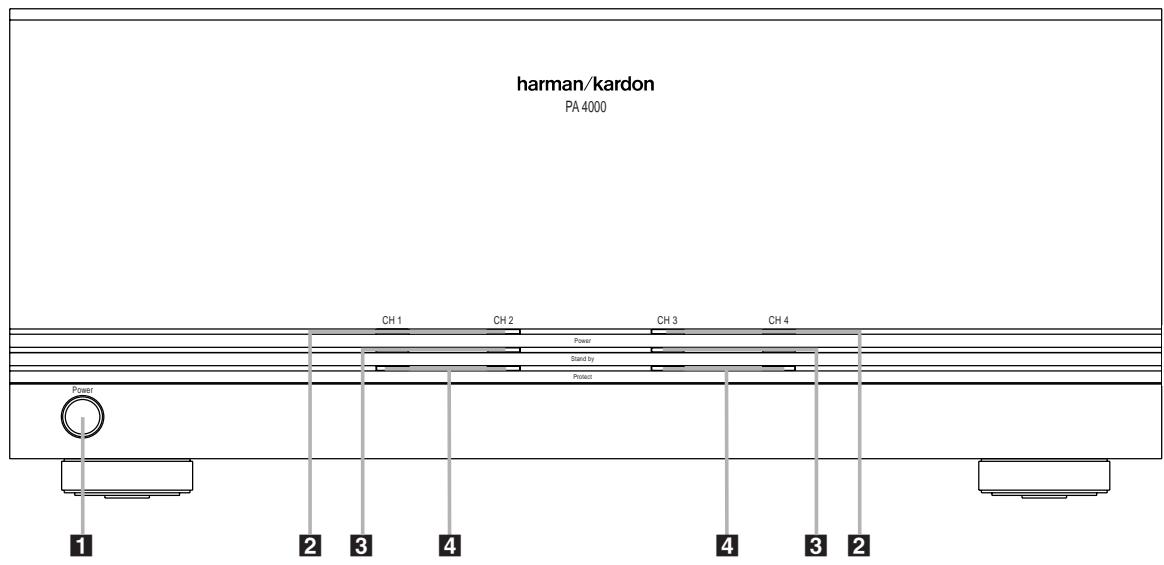
1 Power Switch
2 Power Indicators
3 Standby Indicators
4 Protect Indicators
Power Switch: Press this switch to turn the PA 4000 on for manual operation when the Power Control Mode Switch 19 for one or both channel pairs is in the ON position, or to place it in the Standby mode when the Power Control Mode Switch 19 for one or both channel pairs is in either the Music Sense or AC/DC Trigger position.
2 Power Indicators: These indicators will light when any of the channel pairs are on.
3 Standby Indicators: These indicators will light when AC mains power is applied, but when a specific channel pair is not currently active. In this condition, the channel pair associated with the indicator is ready to turn on when a signal is applied to the Trigger Jack 15 or when there is an audio signal applied to either Input Jack 114.
4 Protect Indicators: These indicators will light when one of the channel pairs is in the Protect mode. When one of these indicators lights, turn the unit off immediately and check for a problem, such as a short in the speaker wiring.
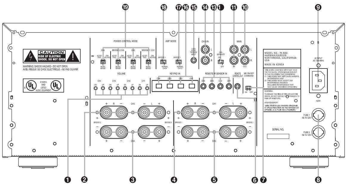
Volume/Output Level Controls
2 Channel 3 Speaker Terminals
3 Channel 4 Speaker Terminals
4 Channel 1 Speaker Terminals
5 Channel 2 Speaker Terminals
6 IR Remote Control Output
7 MR On/Off Command Switch
8 Fuses
9 AC Power Cord Jack
10 Main Amp Output Jacks
1 Main Amp Input Jacks
1 Channel 3 Separate Switch
Remote IR Sensor Inputs
14 Channel 3 Input
15 Trigger Jack
Remote Keypad Inputs
17 Bridge 1 Amplifier Mode Switch
13 Bridge 2 Amplifier Mode Switch
19 Power Control Mode Switches
Volume/Output Level Controls: Press these controls to change the volume level up or down for an individual channel pair in remote room applications. For surround sound applications, use them with the test tone in your receiver or processor to set the output levels. See page 13 for more information.
Channel 3 Speaker Terminals: Connect these terminals to the speaker pair that is fed by the Channel 3 amplifier section.
3 Channel 4 Speaker Terminals: Connect these terminals to the speaker pair that is fed by the Channel 4 amplifier section.
4 Channel 1 Speaker Terminals: Connect these terminals to the speaker pair that is fed by the Channel 1 amplifier section.
⑤ Channel 2 Speaker Terminals: Connect these terminals to the speaker pair that is fed by the Channel 2 amplifier section.
NOTE: When the amplifier is operated in the Bridged configuration, connect the speakers as shown on page 9 or 10.
IR Remote Control Output: Connect this jack to the IR Input jack on another piece of equipment if you wish to use the incoming IR remote signals to control other source or control products. See page 12 for more information.
MR On/Off Command Switch: When the PA 4000 is used in conjunction with a compatible Harman Kardon AVR with multiroom capabilities (such as the AVR 7000, AVR 510 or AVR 310), place this switch in the ON position if you wish to control both the PA 4000 and the AVR via a remote keypad or IR sensor. When used with any other product, the switch position is not applicable.
Fuses: If any of the front-panel Indicators 234 do not light and no sound is heard when a signal is applied, the cause may be a blown fuse. IMPORTANT SAFETY NOTE: Fuses should only be removed or changed with the power cord removed from the unit.
AC Power Cord Jack: Connect the AC power cord supplied with the unit to this jack, and connect the power cord plug to an AC outlet.
10 Main Amp Output Jacks: These jacks carry through the input signal connected to the Main Amp Input Jacks 1. If you wish to continue the input feed to additional amplifiers, connect these jacks to the input jacks of the next amplifier to be used.
1 Main Amp Input Jacks: The signal connected to these input jacks will be sent to all amplifier channels when the Channel 3 Separate Switch is in the OFF position. When the switch is in the ON position it will feed the Channel 1 and Channel 2 amplifier channels at all times, and the Channel 4 amplifier when the Bridge 2 Amplifier Mode Switch is in the Normal position. See pages 9-10 for more information.
1 Channel 3 Separate Switch: This switch determines the input to the Channel 3 amplifier. When the same input signal is used to feed all four amplifier pairs, place the switch in the OFF position. When a separate feed is used for the Channel 3 amplifier so that the PA 4000 carries two separate signals, place the switch in the ON position. See page 10 for more information.
Remote IR Sensor Inputs: When optional remote IR sensors are used to control another piece of equipment, connect them to these jacks.
14 Channel 3 Input: When you wish to have a separate signal feed the Channel 3 amplifier for use in dual-zone or a mix of surround-channel and single-zone use, connect the feed from the source to these jacks. Note that in order for these input jacks to be active, the Channel 3 Separate Switch 1 must be in the ON position.
15 Trigger Jack: Connect this jack to the output of a compatible product capable of feeding a 3-volt to 30-volt signal to the jack when amplifier operation is desired. When one of the channel pairs has a Power Control Mode Switch 19 set to the far left, or AC/DC trigger, position, that channel pair will automatically turn on when the low-voltage trigger signal is present.
Remote Keypad Inputs: When optional, compatible keypads are used to control the volume and power for a remote room location, connect them to these jacks.
Bridge 1 Amplifier Mode Switch: This switch determines whether the Channel 1 and Channel 2 amplifiers operate separately or as a bridged pair for higher power. The following two modes are available:
- When the switch is in the right position, over the phrase "NORMAL CH1/2", the Channel 1 and Channel 2 amplifiers will operate separately.
- When the switch is in the left position, below the phrase "BRIDGE 1", the Channel 1 and Channel 2 amplifiers will be bridged together to operate as a single amplifier.
Bridge 2 Amplifier Mode Switch: This switch determines whether the Channel 3 and Channel 4 amplifiers operate separately or as a bridged pair for higher power. The following two modes are available:
-
When the switch is in the right position, over the phrase "NORMAL CH3/4", the Channel 3 and Channel 4 amplifiers will operate separately. Note that when the Channel 3 Separate Switch 1 is in the ON position, the source connected to the Channel 3 Input Jacks 14 will feed only the Channel 3 amplifier in this mode, while the Channel 4 amplifier will receive the source connected to the Main Amp Input Jacks 15.
-
When the switch is in the left position, below the phrase "BRIDGE 2", the Channel 3 and Channel 4 amplifiers will be bridged together to operate as a single amplifier. Note that when the Channel 3 Separate Switch 1 is in the ON position, the source connected to the Channel 3 Input Jacks 14 will feed the bridged amplifier sections in this mode.
IMPORTANT NOTES ON THE AMPLIFIER MODE SWITCHES:
- THE POWER CORD MUST BE REMOVED FROM THE UNIT BEFORE MAKING A CHANGE TO Either OF THESE SWITCHES.
- When either of the amplifier pairs is used in the Bridged mode, be certain to connect the speakers using the vertically oriented terminals marked for "Bridge" operation at the left and right sides of the speaker terminals, NOT the horizontally oriented terminals used for standard amplifier operation. See pages 9-10 for more information.
- The plastic switch guard surrounding these switches is designed to prevent accidental movement of the switches, which may cause serious damage to the PA 4000 that is not covered by the warranty. Be certain to replace the guard after changing the Bridge mode.
19 Power Control Mode Switches: (One for each channel pair) This three-position switch determines the method by which the PA 4000 will be placed in the active, or ON, mode:
- When the switch is in the far right position under "ON/KEYPAD", the unit will be turned on when the front-panel Power Switch 1 is pressed in.
- When the switch is in the middle position, over the words "MUSIC SENSE", the unit will automatically turn on when an audio signal is present at the Input Jacks 114. The unit will automatically turn off when there is no signal present for 10 to 15 minutes.
- When the switch is in the far left position, under the phrase "AC/DC TRIGGER", the unit will automatically turn on when a 3-volt to 30-volt signal is applied to the Trigger Jack 15.
SAFETY NOTE: When making connections between any source components such as AV receivers, surround processors or multiroom controllers and the PA 4000, or when making any connections to speakers, be certain that both the source device and the PA 4000 are turned off. To ensure that there will be no unwanted signal transients that can damage equipment or speakers, it is always best to unplug all equipment before making any connections. Modern electronic products often have a "standby" mode that may be activated even though the product may appear to be turned off.
Power Control Connections
The PA 4000 features a built-in remote turn-on system that will automatically turn on any of the amplifier pairs in a number of ways. Depending on your specific application, the unit may be turned on manually using the Power
Switch 1, or via automatic sensing of either an input source or a low-voltage trigger signal. For manual operation, no special installation is required. For automatic turn-on, follow the instructions below for the chosen trigger method. The PA 4000 may also be controlled via optional remote room keypads.
Note that when the unit is operated in the standard, four-output mode, each of the channel pairs may be operated by the same trigger method, or they may be turned on via different methods.
Manual Operation
To operate the PA 4000 manually, with power on/off controlled by the front-panel Power Switch 1, place the Power Control Mode Switch 19 for any of the channels at the far right, under the phrase "ON/KEYPAD". When the switch is in this position, simply press the Power Switch 1 to turn the unit on or off.
Remote Turn-On From an External Device Using the Low-Voltage Trigger
To configure the PA 4000 so that any of the channel pairs turn on automatically in response to a low-voltage trigger signal, follow these steps:
- Place the Power Control Mode Switch 19 for either channel in the far left position, so that the switch is under the phrase "AC/DC TRIGGER".
2a. To trigger the amplifier from a device such as a preamp surround processor or multi-room controller with a built-in trigger jack, connect one end of a cable with a 3.5mm mono mini- plug to the Trigger Jack 15 on the PA 4000. Connect the other end to a matching jack on the device that will provide a 3-volt to 30-volt signal when the unit is to be turned on.
or
2b. To trigger the amplifier using the switched AC accessory outlet on an AV receiver or other source device, purchase a small AC to DC power converter, as is typically used to replace the batteries in portable electronics devices. Select a model that is capable of delivering 3 to 12 volts DC, and make certain that one of the "tips" provided with the unit is a 3.5mm miniplug. Plug the transformer end of the converter into the switched AC output on the source product, and connect the 3.5mm miniplug to the Trigger Jack 15.
NOTE: When connections are made to any of the PA 4000's trigger jacks, make certain that the plugs are wired with the positive connection to the plug's tip and the negative connection to the plug's ring/sleeve.
- Press the Power Switch 1 in so that it is engaged, and note that the Standby Indicator 3 will light for the channel pairs selected for trigger control operation.
When the source control unit providing the power is turned on, the PA 4000 will automatically turn on. When the source unit is turned off, the PA 4000 will return to the Standby mode after 10 to 15 minutes.
Remote Turn-On Using Music Sense
To configure the PA 4000 so that any of the channel pairs turn on automatically when the amplifier is receiving an audio signal, follow these steps:
- Connect the audio input as normal to the audio Input Jacks 114.
- For each channel pair that you wish to control using an incoming audio signal, slide the Power Control Mode Switch 19 to the center position so that the switch is over the words "MUSIC SENSE".
- Press the Power Switch 1 in so that it is engaged, and note that the Standby Indicator 3 will light for the channel pair selected for trigger control operation.
In this configuration, the PA 4000 will automatically turn on whenever it is receiving an audio input signal. The unit will return to the Standby mode 10 to 15 minutes after the audio signal stops.
NOTE: When the PA 4000 is used in the Bridged mode, use the Power Control Mode Switch marked "CH1" or "CH3" for Bridge 1 or Bridge 2 configuration, respectively, to make the settings for the desired turn-on mode.
Keypad Control
The PA 4000 may also be turned on or off, and the volume level to any of the channels controlled using optional compatible remote keypads. To use the keypads, follow the instructions supplied with them, and configure the PA 4000 using the following steps:
- Connect the remote room keystads to the Keypad In Jacks 16 for the channel pairs that will be controlled. When the unit is being operated in a bridged mode, connect the keystads to either the CH1 or CH3 jack, as appropriate.
- Place the Power Control Mode Switch 19 for the channel pairs to be controlled remotely in the far right position, under the words "ON/KEYPAD".
- Press the Power Switch 1 in so that it is engaged and note that the Standby Indicator will light for the channel pairs selected for keypad control operation.
- The unit will turn on or off in response to commands made via the remote control keypads.
Channel Configurations, Audio
Connections and Speaker Connections
The PA 4000 is a versatile multichannel, multipurpose amplifier that is designed to operate in a variety of operating modes. Depending on your specific application requirements, the PA 4000 can power two, three or four output pairs and it can feed all outputs from a single source, or two different sources may be used. The specifics of how the audio inputs and speaker outputs are connected will vary according to which of the following operational modes is chosen:
- One Input/Four Outputs: In this configuration, a single source is fed to four separate speaker pairs. Each speaker pair may be adjusted individually for output/volume level. This configuration is typically used for multiroom applications where a single source is sent to four different room areas.
- One Input/Three Outputs: In this configuration, a single source is fed to three separate speaker pairs, one with high power output and two with lower power output. Each speaker pair may be adjusted individually for output/volume level. This configuration may be used for multiroom applications where one room location requires higher power due to speaker efficiency or room size considerations, while two other rooms receive a lower power feed of the same source.
- One Input/Two Outputs: In this configuration, a single source is fed to two separate, high-power speaker pairs. Each speaker pair may be adjusted individually for output/volume level. This configuration is used where two high-power output channels are required for either multiroom use or to power the additional rear surround channels in 7.1 surround system installations.
- Two Inputs/Four Outputs: In this configuration, one input source is fed to three output pairs while a separate input source is fed to an additional output pair. Each speaker pair may be adjusted individually for output/volume. This configuration is used in multi-zone/multiroom applications where one input source is fed to three remote room locations and a second, separate source is fed to a different remote room.
- Two Inputs/Three Outputs: In this configuration, one input source is fed to two output pairs, one high-power and one with lower power output. At the same time, a separate input source is fed to an additional output pair. Each speaker pair may be adjusted individually for output/volume. This configuration is used in multizone/multiroom applications
where one room requires a high-power feed, while two other rooms may be fed a separate source with a lower power feed. This configuration may also be used to send one high-power feed to the rear channels of a 7.1 surround system while a separate feed is sent to two remote room locations.
- Two Inputs/Two Outputs: In this configuration, one input source is fed to a single, high-power output pair, while a separate input source is fed to an additional high-power output pair. Each speaker pair may be adjusted individually for output/volume. This configuration may be used to simultaneously power the rear channels of a 7.1 surround system while a separate high-power feed is available for a remote zone room.
IMPORTANT SAFETY NOTE: When making the connections shown on this page, be certain that the AC power cord is disconnected from the PA 4000. This will prevent damage to the amplifier and speakers due to unintended automatic turn-on.
One Input/Four Outputs
This is the standard configuration, and it is the way the unit is shipped from the factory. If you wish to have one input feed sent to all four amplifier channel pairs, leave the Amplifier Mode Switches as they are and connect the audio source to the Main Input 1. For this configuration, the speakers should be connected as shown in Figure 1, with each channel connected to the appropriate terminals
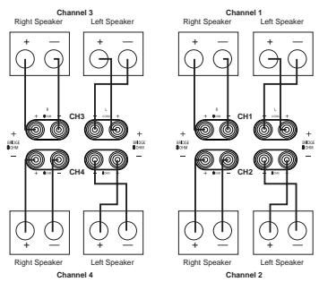
2/3/4/5
Figure 1
One Input/Three Outputs
In this configuration, the same input signal is sent to all speakers, but the Channel 1 and Channel 2 amplifiers are bridged together to form a higher-output channel.
When this option is desired, connect the speaker pair for the high-power channel as shown in Figure 2. Note that markings for
"Bridge 1" should be used, with the connections to the proper "+" and "-" terminals with the two outer-oriented, vertically binding posts on each side of the channel pair, as opposed to the horizontal orientation of normal speaker connections. DO NOT use the standard channel output and polarity markings for the Channel 1 and Channel 2 amplifiers.
The remaining two speaker pairs for Channel 3 and Channel 4 are connected as shown in Figure 2, using the standard markings.
In addition to the speaker connections, the following steps must be followed for this configuration:
- Connect the audio input source to the Main Amp Input Jacks ①.
- Locate the Bridge 1 Amplifier Mode Switch ⑦ on the rear panel, and use a #1 Phillips screwdriver to carefully remove the screws on either side of the plastic switch guard that is around the switch.
- Remove the plastic guard and set it aside with the screws.
- Slide the switch to the left so that it is under the phrase "BRIDGE 1".
- Replace the plastic switch guard with the two screws so that the switch is secured in the proper position.
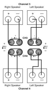
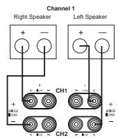
Figure 2
One Input/Two Outputs
In this configuration, the same signal is sent to all speakers to deliver two high-power channel pairs.
When this option is desired, connect the two speaker pairs as shown in Figure 3. Note that markings for "Bridge 1" and "Bridge 2" should be used, with the connections for all speakers made to the proper "+" and - terminals with the outer two vertically oriented binding posts on each side of the channel pair, as opposed to the horizontal orientation of normal speaker connections. DO NOT use the standard channel output and polarity markings for any of the speaker connections.
In addition to the speaker connections, the following steps must be followed for this configuration:
- Connect the audio input source to the Main Amp Input Jacks 1.
- Locate both the Bridge 1 Amplifier Mode Switch ⑰ and the Bridge 2 Amplifier Mode Switch ⑱ on the rear panel, and use a #1 Phillips screwdriver to carefully remove the screws on either side of the plastic switch guards that are around each of the switches.
- Remove both plastic guards and set them aside with the screws.
- Slide both switches to the left so each one is under the word "BRIDGE".
- Replace the plastic switch guards with the two screws so that both switches are secured in their proper position.
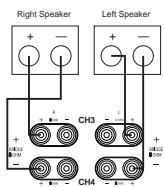
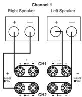
Figure 3
Two Inputs/Four Outputs
In this configuration, there are four speaker pair outputs, with three channels being fed by one input source and one channel being fed by a second, separate source.
Connect the speakers and audio inputs as follows:
- Connect the source that is to be fed to three speakers to the Main Amp Input Jacks ①. The speakers that are to receive this signal should be connected to the Channel 1 Speaker Output Terminals ④, the Channel 2 Speaker Output Terminals ⑤ and the Channel 4 Speaker Output Terminals ③ using the standard speaker wiring markings on the rear panel, as shown in Figure 1.
- Connect the source that is to be fed to only one channel to the Channel 3 Input Jack 14.
- Move the Channel 3 Separate Switch 1 to the left so that it is under the word "ON".
- Connect the speaker pair that will receive the separate input feed to the Channel 3 Speaker Terminals using the normal wiring connections and markings as shown in Figure 1.
- Make no changes to the Amplifier Mode Switches 17/18. Leave them in their factory positions with the switch over the word "NORMAL".
Two Inputs/Three Outputs
In this configuration, there are three speaker pair outputs, with one high-power and one lower-power pair receiving the same input, while a second, separate input is sent to an additional speaker pair.
Connect the speakers and audio inputs as follows:
- Connect the source that is to be fed to the high-power speaker set and the lower-power speaker set to the Main Amp Input Jacks
- Connect the higher-power speaker set as shown in Figure 2 to the speaker terminals marked "Bridge 1". Make certain that the connections for these speakers are made to the proper "+" and "-" terminals with the two vertically oriented binding posts on each side of the channel pair, as opposed to the horizontal orientation of normal speaker connections. DO NOT use the standard channel output and polarity markings for these speaker connections.
- The speaker set that is to receive the lower power signal should be connected to the Channel 4 Speaker Output Terminals ③ using the standard speaker wiring markings on the rear panel as shown in Figure 2.
- Connect the source that is to be fed to only one channel to the Channel 3 Input Jack 14.
- Move the Channel 3 Separate Switch 1 to the left so that it is under the word "ON".
- Connect the speaker pair that will receive the separate input feed to the Channel 3 Speaker Terminals ② using the normal wiring connections and markings as shown in Figure 1.
- Locate the Bridge 1 Amplifier Mode
Switch 17 on the rear panel, and use a #1 Phillips screwdriver to carefully remove the screws on either side of the plastic switch guard that is around the switch.
- Remove the plastic guard and set it aside with the screws.
- Slide the switch to the left so that it is under the phrase "BRIDGE 1".
- Replace the plastic switch guard with the two screws so that the switch is secured in the proper position.
Two Inputs/Two Outputs
In this configuration, the PA 4000 acts as a dual-stereo amplifier, with two separate signals being sent to high-power amplifiers.
Connect the speakers and audio inputs as follows:
- Connect one input source to the Main Amp Input Jacks 1. Connect the speakers that
are to receive this signal to the speaker terminals marked "Bridge 1", as shown in Figure 3. Make certain that the connections for these speakers are made to the proper "+" and "-" terminals with the two vertically oriented binding posts on each side of the channel pair, as opposed to the horizontal orientation of normal speaker connections. DO NOT use the standard channel output and polarity markings for these speaker connections.
- Connect the other input source to the Channel 3 Input Jack 14. Connect the speakers that are to receive this signal to the speaker terminals marked "Bridge 2", as shown in Figure 3. Make certain that the connections for these speakers are made to the proper "+" and "-" terminals with the two vertically oriented binding posts on each side of the channel pair, as opposed to the horizontal orientation of normal speaker connections. DO NOT use the standard channel output and polarity markings for these speaker connections.
- Move the Channel 3 Separate Switch ① to the left so that it is under the word "ON".
- Locate both the Bridge 1 Amplifier Mode Switch ⑦ and the Bridge 2 Amplifier Mode Switch ⑧ on the rear panel, and use a #1 Phillips screwdriver to carefully remove the screws on either side of the plastic switch guards that are around each of the switches.
- Remove both plastic guards and set them aside with the screws.
- Slide both switches to the left so each one is under the word "BRIDGE".
- Replace the plastic switch guards with the two screws so that both switches are secured in their proper position.
Note for Audio Connections
When making connections with the RCA-type plugs on interconnect cables, make certain to gently but firmly insert them into the jacks on the back of the PA 4000. Loose connections can cause intermittent sound and may damage your speakers. The barrel assembly of some high-quality RCA plugs may be very tight, and it is important to ensure a proper connection between the interconnection cable and the input jack.
Speaker Wire Connections
Regardless of the channel configuration used, the final step of the installation process is to connect the amplifier to your speakers, using high-quality cable. The PA 4000 is equipped with binding post terminals that accept bare wire, spade lugs or banana-type plugs, when they are permitted by local safety agencies. Once you have located the proper speaker terminals for the type of output configuration in use, connect your speakers using the following guidelines.
To ensure that the high-quality signals produced by your PA 4000 are carried to your speakers without loss of clarity or resolution, we recommend that you use high-quality speaker cable. Many brands of cable are available, and the choice of cable may be influenced by the distance between your speakers and the amplifier, the type of speakers you use, personal preferences and other factors. Your dealer or installer is a valuable resource to consult in selecting the proper cable for connections between your amplifier and speakers.
Regardless of the brand or type of cable selected, we recommend that you use a cable constructed of fine, multistrand copper with a gauge of 14 or larger. Remember that in specifying cable, the lower the number, the thicker the cable.
Cable with a gauge of 16 may be used for short runs of less than ten feet. We do not recommend that you use any cables with an AWG equivalent of 18 or higher, due to the power loss and degradation in performance that will occur.
Cables that are run inside walls should have the appropriate markings to indicate that they are listed with UL, CSA or other testing agency standards. Questions about cables inside walls should be referred to a qualified installer or a licensed electrical contractor who is familiar with the NEC and/or the applicable local building codes in your area.
If bare wire is used for the connections, strip approximately 1/2 inch to 3/4 inch of insulation from the end of each wire and carefully twist the strands of each conductor together. Be careful not to cut the individual strands or twist them off; for optimal performance, all strands must be used.
Then, loosen the knobs of the speaker output terminals far enough so that the pass-through hole is revealed. In order to preserve proper stereo imaging and low-frequency reproduction, it is essential that proper polarity be observed when connecting speakers to the PA 4000. Be sure to connect the negative terminal for each channel on the PA 4000 to the negative terminal on the speaker, and the positive terminal on the PA 4000 to the positive terminal on the speaker. Note that one conductor of the speaker cable will have no markings and the other will have a red line, brand name markings, a black thread or some other positive indication. Follow the proper connection instructions for your system with regard to which terminals are used. The small speaker icons next to each pair of terminal posts will guide you to the correct connections. When the connections are made, twist the cap back so that the connection is secured, but do not overtighten or use tools, as this may break the delicate wire strands and decrease system performance.
If you are using spade lugs, connect them to the wire using the manufacturer's instructions and then loosen the caps on the speaker terminals. Place the lugs between the plastic cap and the back of the terminal, as if it were a horseshoe on the game's post. Be sure to observe proper polarity, using the appropriate speaker hook-up icons for your system's configuration. Tighten with your fingers to obtain a positive contact.
When banana plugs are permitted, connections may be made by simply inserting the jack affixed to your speaker wire into the hole provided on the rear of the colored screw caps on the binding posts. Before using banana-type jacks, make certain that the plastic screw caps are firmly tightened down by turning them in a clockwise direction until they are snug against the chassis. This will ensure that the maximum surface area of the plug is in contact with the jack. Be certain to observe proper polarity.
Finally, run the cables to the speaker locations. Where possible, it is recommended that the length of cable connecting any pair of speakers be identical, even though one speaker may be physically closer to the amplifier than the other. Do not coil any excess cable, as this may become an inductor that creates frequency response variations in your system. Finally, connect the wires to the speakers,
again, being certain to observe proper polarity. Remember to connect your "negative" or "black" wire to the matching terminal on the speaker. Similarly, the "positive" or "red" wire should be connected to the like terminal on the speaker.
When making connections using bridged amplifier configurations, be certain to use the correct positive and negative terminals for bridged applications. In bridged applications, the negative speaker connector terminal will be red even though the connection is properly marked as negative.
NOTE: While most speaker manufacturers adhere to an industry convention of using black terminals for negative and red ones for positive, some manufacturers may vary from this configuration. To ensure proper phase connections and optimal performance, consult the identification plate on your speaker terminals, or the speaker's manual to verify polarity. If you do not know the polarity of your speaker, ask your dealer or installer for advice before proceeding, or consult the speaker's manufacturer.
As a general rule, avoid running input signal or speaker wire connections in parallel with each other, or with AC power cords. This can result in undesired hum or other interference that will greatly degrade signal performance.
Parallel Output Connection
In some multiroom systems, you may wish to have the same signal fed to multiple amplifiers to power additional rooms on a single zone. To do this, connect the Main Amp Output Jacks
10 to the input of the additional, optional power amplifiers. Note that signal feed sent to these jacks is the feed from the Main
Amplifier Input Jacks 1. The source connected to the Channel 3 Input Jacks 4 may not be sent to a parallel output.
Infrared Control Connections
The PA 4000 allows you to anchor a multi-room installation by receiving IR remote control commands from remote rooms and, where compatible, using them to control other source-control components. IR connections are made as follows:
Connect the incoming IR feed from a remote room to the appropriate Remote IR Sensor
Input 13. To send the incoming IR signals onward to source components or an AV receiver or other controller, connect the IR Remote
Control Output 6 to the IR input of the desired component to be controlled.
When the PA 4000 is used in conjunction with a compatible, multiroom-equipped, Harman Kardon AV receiver, such as the AVR 7000, AVR 510 or AVR 310, you may also use the remote-room IR commands to turn the multiroom feature of the AVR on and off while the volume is controlled in the PA 4000. To enable this function, slide the MR On/Off
Command Switch ⑦ to the left so that it is over the word "ON".
Notes for Infrared Connections:
- When the optional keycaps incorporating IR sensors from third-party suppliers are connected to any of the Remote Keypad Inputs 16, do not make any connections to the Remote IR Sensor Input 13 for that amplifier channel pair.
- When the optional keypads are connected, the output of the IR sensor built in to the keypad should be connected to the AV receiver or other devices to be controlled using the IR Remote Control Output ⑥.
Keypad Connections
The PA 4000 is designed for use with optional, compatible remote room keypads. These keypads will control the volume and power on/off for a particular room's feed. In addition, the keypad may include a built-in IR remote sensor that may be used to carry control signals to source equipment, a receiver or a multiroom controller. When these keypads are used, connect the keypad from a remote room to the
Remote Keypad Input Jack 16 matching the respective room location.
When the PA 4000 is used in conjunction with a compatible, multiroom-equipped, Harman Kardon AV receiver, such as the AVR 7000, AVR 510 or AVR 310, you may also use the remote room IR commands to turn the multiroom feature of the AVR on and off while the volume is controlled in the PA 4000. To enable this function, slide the MR On/Off
Command Switch ⑦ to the left so that it is over the word "ON".
NOTE: The connection jack used for the keypads is an RJ-45-style jack that is identical to that used for some telephone or data applications. However, these jacks are used by the PA 4000 solely for use with compatible keypads. They should not be used for any other purpose or connected to any other device.
AC Power Connection
The final step in the installation of the PA 4000 is to connect the power cord. First, connect the female end of the cord into the AC Power
Cord Jack 9 on the rear panel. Once the cord as been firmly connected to the PA 4000, insert the plug end into an AC power outlet.
SAFETY NOTES:
- Due to the current draw of the PA 4000, DO NOT connect the power cord to the accessory outlet on audio/video components.
- Should the power cord become lost or damaged, be certain to replace it with a replacement that meets or exceeds the original specifications. Use of power cords with insufficient capacity, such as those used with computers or office equipment, may create a safety hazard.
Operation of the PA 4000 is simple. In normal use, there are no controls to adjust once the installation is complete.
After all connections have been made to the amplifier's inputs and speaker terminals, and the AC power cord has been connected, the way in which the unit turns on is determined by the settings for the Power Control Mode Switches ⑨. Depending on the settings, as described on page 8, the amplifier will turn on in one of these three ways:
- When a Power Control Mode Switch 19 is set to the right, in the "ON/KEYPAD" position, the PA 4000 will turn on when the Power Switch 1 is pressed in. Press the switch again to turn the amp off.
- When a Power Control Mode Switch 19 is set to the left, in the "AC/DC TRIGGER" position, the Power Switch 1 should be pressed in to place the PA 4000 in the Standby mode. The unit will now turn on automatically when a low-voltage signal is present at the Trigger Jack 15.
- When a Power Control Mode Switch is set in the middle, in the "MUSIC SENSE" position, the Power Switch 1 should be pressed in to place the PA 4000 in the Standby mode. The unit will now turn on automatically whenever an audio signal is present. The unit will return to the Standby mode 10 to 15 minutes after the audio signal is removed.
- When optional remote-room keypads are connected to the PA 4000 for one of the channel pairs and the appropriate Power Control Mode Switch is set to the right, the Power Switch should be pressed in to place the PA 4000 in the Standby mode. The appropriate amplifier pair will now turn on when a Power On command is received from one of the remote rooms.
As a general rule, it's always a good idea to turn on your amplifier LAST. This avoids the possibility of any turn-on pops or transients from other equipment being amplified and sent to your speakers where they may cause damage. Always start with a low volume level on your receiver, controller or preamp to avoid damage to your speakers.
You are now ready to enjoy the finest sonic performance available.
SAFETY NOTE: To prevent unintended operation, remember to turn the unit completely off when it will not be used for an extended period of time. This is done by pressing the Power Switch 1 and noting that the Standby Indicator 3 goes out. This will prevent the
automatic turn-on circuits from accidentally turning the amplifier on during your absence.
Volume Control and Output Level Adjustment
Depending on the specifics of a particular installation, the volume control for any of the channel pairs may be controlled in a number of ways. Depending on the specific application, you may choose to use more than one volume control method at a time.
The following options are available:
- When there is no volume control in a remote room location, the volume level for that room should be adjusted using the Volume/Output Level Controls 1 for that specific channel. Press the appropriate buttons to raise (UP) or lower (DN) the volume until the desired level is obtained. Note that when there is a volume control active for the channel pair feed from the input source (such as a receiver or multiroom controller) changing that volume level will result in a change to the volume in the remote room.
- When there is a volume control in a remote room location (such as an in-wall autoformer) you will need to set an output level from the PA 4000, which will then be controlled further in the remote room. To do this, we suggest setting the remote room volume control to the maximum, and then adjusting the PA 4000 output by using the Volume/Output Level Controls for the appropriate amplifier channel pair until the level in the remote room is as loud as would ever be required, and perhaps a bit louder, as long as there is no distortion of the audio signal. At that point, the remote room control may be used to lower the volume level as needed. Note that when there is a volume control for the channel pair feed at the input source (such as a receiver or multiroom controller) changing that volume level will result in a change to the volume in the remote room.
- When the remote room volume is controlled through the optional in-wall keypads, no adjustment to the rear-panel Volume Control switches is needed.
- When any of the channels on the PA 4000 are used in conjunction with a surround sound system, first leave the rear-panel Volume Controls at their factory preset level and make your output level adjustments using the controls provided through your AV receiver or surround processor. However, if those adjustments do not produce a level setting that matches the output from the channels being fed by other amplifiers, you may raise or lower the output level from the PA 4000 as required, using these controls.
Turn-On Volume Level Limits
In normal operation, when any channel pair in the PA 4000 is turned on, it will return to the last volume setting in use before the unit was turned off or placed into the standby mode. However, to prevent possible speaker damage or disturbances to the occupants of a remote room, the PA 4000 will automatically limit the volume level at turn-on to either the factory preset of -12dB or to a user-determined maximum level. This option is particularly useful when the optional remote keypads are in use.
To change the Turn-On Volume Level limit for any of the channel pairs, follow these steps individually for each channel pair to be adjusted:
- Place the Power Control Mode Switch 19 to the far right, in the "ON/KEYPAD" position.
- Use the appropriate Volume Control/Output Level Control 1 for the channel to be adjusted until the desired maximum turn-on level is reached.
- Move the Power Control Mode Switch 19 to the middle "MUSIC SENSE" position.
- Leave the Power Control Mode Switch 19 in the "MUSIC SENSE" position for at least one half of a second, and no more than 4 seconds.
- Return the Power Control Mode Switch 19 to the "ON/KEYPAD" position.
To return the Turn-On Volume Level limit for any channel pair to the factory preset of -12dB , follow these steps individually for each channel pair to be adjusted:
- Place the Power Control Mode Switch 19 to the far right, in the "ON/KEYPAD" position.
- Move the Power Control Mode Switch 19 to the middle "MUSIC SENSE" position.
- Leave the Power Control Mode Switch 19 in the MUSIC SENSE position for at least 4 seconds, to no more than 10 seconds.
- Return the Power Control Mode Switch 19 to the "ON/KEYPAD" position.
Notes on using the Turn-On Volume Level Limit:
- The volume settings for the Turn-On Level are used only when any channel is first turned on. After turn-on the volume may be adjusted to any point in its range.
- Consult the instructions packed with the optional keypads for additional information on changing these settings from the remote room.
If your installation has followed the procedures in this manual, you should enjoy many years of trouble-free operation and high-quality listening enjoyment. The PA 4000 does not contain any user-serviceable parts. If you suspect a problem that may require service assistance, contact your dealer, installer or an authorized Harman Kardon service center.
You may also contact Harman Kardon at www.harmankardon.com.
It is important that any repairs be carried out only by an authorized Harman Kardon service agent to ensure proper service and preserve the protection of your Limited Warranty. It's a good idea to keep your sales slip or receipt in a safe place (along with this manual) so that it will be available to verify the purchase date for warranty claims.
The items listed below are a brief guide to minor problems that may arise with audio equipment such as the PA 4000. Before taking a unit in for service, you should check to see whether any of these hints solve the problem. If these solutions do not rectify the problem or if the problem recurs, contact your dealer or an authorized Harman Kardon service center for assistance.
Fuse Replacement
In rare situations, the fuses protecting the PA 4000's output stages may blow to protect the unit and your speakers. If any amplifier pair does not operate, and if the front-panel indicators do not light, it is possible that a short or overload condition has caused one of the fuses to blow.
If you suspect that a fuse has blown, follow these steps:
-
Turn the amp off and remove the power cord.
-
Check all speaker wire connections – both on the amplifier side and on the speakers – to make certain that there are no shorts.
- Remove each fuse and then, if a fuse has blown, replace it with a replacement of the same type and rating, as shown on the rear panel.
- Reconnect the power cord and turn the amplifier on again.
If the amplifier continues to blow fuses or go into the Protect mode after all connections have been checked for shorts, there may be an internal problem with the unit. In that case, contact your dealer or an authorized Harman Kardon service center for assistance.
Troubleshooting Guide
| SYMPTOM | CAUSE | SOLUTION |
| Amplifier or one channel will not turn on. | • Power switch turned off (no power light LED) • Remote trigger cable not properly connected • Power Control Mode Switch 19 not set to the proper position | • Turn on power switch. • Verify connection of trigger cable at both ends. • Turn the amp off and remove the power cord and check that the Power Control Mode Switch for the channel that will not turn on is set to the correct position. See page 8. |
| Amplifier turns on, but there's no audio from one or more channels. | • Inputs not connected to proper jack • Speakers not connected properly • Improper settings or levels from processor or controller | • Check input connections. • Check speaker connections. • Check the settings on your preamp, processor or controller. |
| Audio plays, then cuts off. | • Amplifier shorted (Protect Indicator lights) | • Check speaker connections for short circuit. |
| No sound is heard from a channel pair and a Protect Indicator 4 is lit. | • The amplifier has sensed an overload condition or short and has put the amp in the Protect mode to prevent damage to the amp or your speakers | • Turn the amp off and remove the power cord. Check all speaker connections to make certain that there are no shorted conductors. |
| No sound from BOTH Channels 1 and 2 or Channels 3 and 4. | • An overload or short condition may have caused one of the two fuses to blow to prevent damage to the amp or your speakers | • Turn the amp off and remove the power cord. Check the fuses and replace them, if needed, with a fuse of the same rating. |
Power Output
Standard Operation
8 x 45 watts @ 8 ohms, 20Hz - 20kHz, <0.07% THD, all channels driven
Bridged Mode 1
2 x 100 watts plus 4 x 45 watts @ 8 ohms, 20Hz - 20kHz, <0.07% THD, all channels driven
Bridged Mode 2
4 x 100 watts @ 8 ohms, 20Hz - 20kHz, <0.07% THD, all channels driven
High-Current Capability
± 45 amps
Frequency Response
<1Hz - 200kHz, ±3dB at 1 watt
Signal-to-Noise Ratio
110dB at rated power 45 watts
THD/IMD
Less than 0.07% at rated output
Input Impedance
47K ohms
Input Sensitivity
1 volt for rated output
Remote Trigger Voltage
3-30 volts AC/DC
Remote Trigger Impedance
20K ohms
Keypad IR Sensor DC Supply
12V, 10mA
Dimensions (H x W x D)
7-5/16" x 17-3/8" x 18-5/16"
185mm x 442mm x 465mm
Weight
47 lb/21.4kg
Power Requirements
120VAC, 50Hz/60Hz
520 watts, maximum
- PA 4000 Bridgeable Multichannel/Multipurpose Amplifier
- Typographical Conventions
- Features
- CAUTION
- RISK OF ELECTRIC SHOCK DO NOT OPEN
- Important Safety Information
- Verify Line Voltage Before Use
- Verify AC Circuit Capacity Before Use
- Do Not Use Extension Cords
- Handle the AC Power Cord Gently
- Do Not Open the Cabinet
- Installation Location
- Cleaning
- Moving the Unit
- Unpacking and Installation
- IMPORTANT NOTES ON THE AMPLIFIER MODE SWITCHES:
- Power Control Connections
- Manual Operation
- Remote Turn-On From an External Device Using the Low-Voltage Trigger
- Remote Turn-On Using Music Sense
- Keypad Control
- Channel Configurations, Audio
- Connections and Speaker Connections
- One Input/Four Outputs
- One Input/Three Outputs
- One Input/Two Outputs
- Two Inputs/Four Outputs
- Two Inputs/Three Outputs
- Two Inputs/Two Outputs
- Note for Audio Connections
- Speaker Wire Connections
- Parallel Output Connection
- Infrared Control Connections
- Notes for Infrared Connections:
- Keypad Connections
- AC Power Connection
- SAFETY NOTES:
- Volume Control and Output Level Adjustment
- Turn-On Volume Level Limits
- Fuse Replacement
Brand : HARMAN KARDON
Model : PA 4000
Category : Audio Amplifier