
Gryphon BT200 - Barcode scanners DATALOGIC - Free user manual and instructions
Find the device manual for free Gryphon BT200 DATALOGIC in PDF.


| Product Type | Barcode Scanner |
| Brand | Datalogic |
| Model | Gryphon BT200 |
| Connectivity | Bluetooth Class 1 (up to 100 m) and USB/RS-232 via cradle |
| Battery Type | Rechargeable Li-Ion 3.7V, 2100 mAh |
| Scanning Technology | Linear Laser or 2D Imager (model dependent) |
| Scan Speed | Up to 270 scans/sec |
| Reading Distance | Up to 1 m (4 mil) for standard barcodes |
| Barcode Symbologies | All standard 1D and 2D codes (model dependent) |
| Operating Temperature | 0°C to 50°C |
| Drop Resistance | 1.5 m onto concrete |
| Dimensions (L x W x H) | 180 x 85 x 55 mm |
| Weight | 200 g (with battery) |
| Charging Time | Approx. 4 hours |
| Operating Time | Up to 40,000 scans per charge |
| Interfaces | USB Keyboard, USB COM, RS-232, Wand Emulation |
| Warranty | Standard 2 years |
| Cleaning Instructions | Wipe with dry soft cloth; use mild detergent if needed |
| Included Accessories | Scanner, cradle, USB cable, power supply, manual |
Frequently Asked Questions - Gryphon BT200 DATALOGIC
User questions about Gryphon BT200 DATALOGIC
0 question about this device. Answer the ones you know or ask your own.
Ask a new question about this device
Download the instructions for your Barcode scanners in PDF format for free! Find your manual Gryphon BT200 - DATALOGIC and take your electronic device back in hand. On this page are published all the documents necessary for the use of your device. Gryphon BT200 by DATALOGIC.
USER MANUAL Gryphon BT200 DATALOGIC
Reference Manual
Datalogic Scanning, Inc. 959 Terry Street Eugene, Oregon 97402 Telephone: (541) 683-5700 Fax: (541) 345-7140
An Unpublished Work - All rights reserved. No part of the contents of this documentation or the procedures described therein may be reproduced or transmitted in any form or by any means without prior written per-mission of Datalogic Scanning, Inc. or its subsidiaries or affiliates ("Datalogic" or "Datalogic Scanning"). Owners of Datalogic products are hereby granted a non-exclusive, revocable license to reproduce and transmit this documentation for the purchaser's own internal business purposes. Purchaser shall not remove or alter any proprietary notices, including copyright notices, contained in this documentation and shall ensure that all notices appear on any reproductions of the documentation.
Should future revisions of this manual be published, you can acquire printed versions by contacting your Datalogic representative. Electronic versions may either be downloadable from the Datalogic website (www.scanning.datalogic.com) or provided on appropriate media. If you visit our website and would like to make comments or suggestions about this or other Datalogic publications, please let us know via the "Contact Datalogic" page.
Disclaimer
Datalogic has taken reasonable measures to provide information in this manual that is complete and accurate, however, Datalogic reserves the right to change any specification at any time without prior notice. Datalogic is a registered trademark of Datalogic S.p.A. in many countries and the Datalogic logo is a trademark of Datalogic S.p.A. all licensed to Datalogic Scanning, Inc. All other trademarks and trade names referred to herein are property of their respective owners.
18/10/2007
GENERAL VIEW ...... viii
COMPLIANCE ix
FCC Compliance....ix
Radio Compliance....ix
LED Class....x
Bluetooth ® Approval....x
Power Supply....x
Patents....x
WEEE Compliance ....x
1 INTRODUCTION .... 1
1.1 Bluetooth ® Definitions 2
2 GRYPHON™ BT POWER....3
2.1 Powering the OM-Gryphon™ BT 3
2.2 Battery Type....4
2.3 Battery Charging 4
2.4 Replacing Gryphon™ BT Batteries 6
3 INITIAL SETUP 7
3.1 OM-Gryphon™ BT Cable Connections....7
3.2 Setting Up Gryphon™ BT with OM-Gryphon™ BT 8
3.2.1 USB Interface Selection 9
3.2.2 RS232 Interface Selection 12
3.2.3 WEDGE Interface Selection.... 13
3.2.4 PEN Emulation Interface Selection 16
3.3 Setting Up Gryphon™ BT with Bluetooth Device 17
3.3.1 Setup for Gryphon™ BT as Slave 18
3.3.2 Setup for Gryphon™ BT as Master 20
4 CONFIGURATION....22
4.1 Configuration Methods 22
4.1.1 Reading Configuration Barcodes 22
4.1.2 Sending Configuration Strings from Host.... 22
4.2 Default Settings.... 23
4.3 Changing Default Settings 26
USB PARAMETERS ...... 27
Handshaking....29
Ack/Nack Protocol....29
Inter-character Delay 30
Rx Timeout....30
Serial Trigger Lock 31
Keyboard Nationality 32
Inter-character Delay 33
Inter-code Delay....33
Keyboard Character Assignment 34
RS232 PARAMETERS 37
Baud Rate 39
Parity 40
Data Bits 40
Stop Bits....41
Handshaking....41
Ack/Nack Protocol....42
Inter-character Delay 42
Rx Timeout....43
Serial Trigger Lock....43
WEDGE PARAMETERS 44
Keyboard Nationality 46
Caps Lock 47
Caps Lock Auto-Recognition (IBM AT compatible only) 47
Num Lock 48
Inter-character Delay 48
Inter-code Delay....49
Keyboard Character Assignment 50
PEN EMULATION 53
Operating Mode 54
Minimum Output Pulse....55
Conversion to Code 39 56
Overflow....56
Output Level....57
Idle Level....57
Inter-Block Delay....58
DATA FORMAT....59
Code Identifier....62
Custom Code Identifier 63
Header 64
Terminator....65
Field Adjustment 66
Field Adjustment Character....67
Code Length Tx 67
Character Replacement 69
Address Stamping....71
Address Delimiter....71
POWER SAVE....72
Scan Rate 73
READING PARAMETERS 74
Hand-Held Operation 76
Stand Operation....76
Hardware Trigger Signal 77
Trigger-off Timeout 77
Flash Mode 78
Reads per Cycle 78
Safety Time....79
Beeper Intensity 79
Beeper Tone 80
Beeper Type 80
Beeper Length 80
PDF Decoding Recognition Intensity 81
Good Read Spot Duration....81
DECODING PARAMETERS....82
Ink Spread....83
Overflow Control 83
Interdigit Control....84
Decoding Safety....84
Puzzle Solver TM 85
CODE SELECTION 86
EAN/UPC Family 88
2/5 Family 92
Code 39 Family....93
Code 128 Family....95
Code 93 96
Codabar Family....97
MSI 99
Plessey 100
Telepen....101
Delta IBM 102
Code 11 103
Code 16K....104
Code 49 104
RSS Codes 105
PDF417.... 106
ADVANCED FORMATTING.... 107
Concatenation.... 109
Advanced Formatting.... 112
Zebra Printer Formatting.... 129
Zebra Printer Format File Selection 131
RADIO PARAMETERS ...... 133
Radio Protocol Timeout 135
Transmission Retry 135
Power-Off Timeout.... 136
Beeper Control for Radio Response 136
ACK/NACK Protocol and Frame Packing 137
User-Friendly Name....137
Auto-Connection (for Master only) 138
Auto Reconnection (for Master only).... 138
Encryption.... 139
Batch Mode....139
5 REFERENCES 140
5.1 USB-COM and RS232 Parameters.... 140
5.1.1 Handshaking....140
5.1.2 ACK/NACK Protocol 141
5.1.3 RX Timeout 142
5.2 Pen Parameters....142
5.2.1 Minimum Output Pulse.... 142
5.2.2 Conversion to Code 39 142
5.2.3 Overflow....142
5.2.4 Output and Idle Levels 143
5.2.5 Inter-Block Delay.... 143
5.3 Data Format.... 143
5.3.1 Header/Terminator Selection 144
5.3.2 Address Stamping....145
5.3.3 Address Delimiter.... 145
5.4 Reading Parameters....145
5.4.1 Hand-Held and Stand Operation.... 145
5.4.2 Hardware Trigger Signal 146
5.4.3 Trigger-Off Timeout.... 146
5.4.4 Reads per Cycle 146
5.4.5 Safety Time....147
5.5 Decoding Parameters 147
5.5.1 Ink-Spread 147
5.5.2 Overflow Control 147
5.5.3 Interdigit Control....147
5.6 Advanced Formatting.... 148
5.6.1 Zebra Printer Formatting 148
5.6.2 Zebra Printer Format File Selection 148
5.7 Common Radio Parameters.... 149
5.7.1 Radio Protocol Timeout 149
5.7.2 Transmission Retry 149
5.7.3 Power-Off Timeout.... 149
5.7.4 Beeper Control for Radio Response 149
5.8 Radio Parameters For BT Device Configurations 150
5.8.1 ACK/NACK Protocol and Frame Packing 150
5.8.2 User Friendly Name 151
5.8.3 Auto-Connection (Master only) 152
5.8.4 Auto-Reconnection (Master only).... 152
5.9 Radio Parameters For OM-Gryphon™ BT Configurations.... 152
5.9.1 Batch Mode.... 152
5.10 Default Parameters for POS Terminals.... 153
6 SYSTEM MANAGEMENT COMMANDS....154
6.1 Radio Management Commands 154
6.2 Gryphon™ BT Management Commands.... 155
6.3 OM-Gryphon™ BT Management Commands 156
6.4 Cradle Charging Management....157
7 TROUBLESHOOTING 158
8 TECHNICAL FEATURES....159
8.1 Gryphon™ BT 159
8.2 OM-Gryphon™ BT 160
8.3 C-Gryphon™ 161
8.4 Status Indicators 162
8.5 Reading Diagrams 164
A HOST CONFIGURATION STRINGS....166
B CODE IDENTIFIER TABLE....179
C HEX AND NUMERIC TABLE 182
GRYPHON™ BT READER

Figure A – Gryphon™ BT Series Reader

Figure B – OM-Gryphon™ BT/C-Gryphon
This device must be opened by qualified personnel only.
The batteries must be removed from the Gryphon™ BT before opening the device.
FCC COMPLIANCE
Modifications or changes to this equipment without the expressed written approval of Datalogic could void the authority to use the equipment.
This device complies with PART 15 of the FCC Rules. Operation is subject to the following two conditions: (1) This device may not cause harmful interference, and (2) this device must accept any interference received, including interference which may cause undesired operation.
OM-Gryphon™ BT
This equipment has been tested and found to comply with the limits for a Class B digital device, pursuant to part 15 of the FCC Rules. These limits are designed to provide reasonable protection against harmful interference in a residential installation. This equipment generates, uses and can radiate radio frequency energy and, if not installed and used in accordance with the instructions, may cause harmful interference to radio communications. However, there is no guarantee that interference will not occur in a particular installation. If this equipment does cause harmful interference to radio or television reception, which can be determined by turning the equipment off and on, the user is encouraged to try to correct the interference by one or more of the following measures:
- Reorient or relocate the receiving antenna.
– Increase the separation between the equipment and receiver. - Connect the equipment into an outlet on a circuit different from that to which the receiver is connected.
- Consult the dealer or an experienced radio/TV technician for help.
RADIO COMPLIANCE
Contact the competent authority responsible for the management of radio frequency devices of your country to verify the eventual necessity of a user license.
Refer to the web site http://europa.eu.int/comm/enterprise/rtte/spectr.htm for further information.
LED CLASS
BLUETOOTH® APPROVAL
This product is equipped with the following certified Bluetooth module:
Product Name: Panasonic Serial Port Module
Bluetooth ID: B01839
Product ID: PAN1440, PAN1450, PAN1540, PAN1550
POWER SUPPLY
For OM-Gryphon™ BT and C-Gryphon
This device is intended to be supplied by a UL Listed or CSA Certified Power Unit marked "Class 2" or "LPS" output rated 9-28 V, minimum 0.9 A which supplies power directly to the unit via the jack connector.
PATENTS
This product is licensed under the following U.S. patent 6,158,661
This product is covered by one or more of the following patents:
U.S. patents: 5,992,740; 6,305,606 B1; 6,517,003 B2; 6,631,846 B2; 6,712,271 B2; 6,808,114 B1; 6,817,525 B2; and 6,834,806 B2
European patents: 851,378 B1; 895,175 B1; 962,880 B1; 997,760 B1; 1,128,315 B1; and 1,164,536 B1.
Additional patents pending.
WEEE COMPLIANCE

1 INTRODUCTION
The Gryphon™ BT (Gryphon™ Bluetooth®) reader is a CCD wireless barcode scanner which is part of one of the Cordless Reading Systems described below:
CSR Kit
When paired with the OM-Gryphon™ BT cradle, Gryphon™ BT builds a Cordless Reading System for the collection, decoding and transmission of barcoded data. OM-Gryphon™ BT can be connected to a Host PC through a USB, RS232, Wedge or Pen emulation cable. The OM-Gryphon™ BT cradle also serves as battery charger for Gryphon™ BT.
CS Kit
Gryphon™ BT can also be used together with a Bluetooth® compatible remote device, to build a Cordless Reading System. The Bluetooth® compatible remote device can be a PC, PDA, printer, etc with a built-in Bluetooth® device or with external Bluetooth® adapter (i.e. Bluetooth® dongle). In this case the C-Gryphon cradle serves as battery charger for Gryphon™ BT.
Datalogic has moved a step ahead in the concept of “instinctive reading”. The new Gryphon™ BT reader series has been developed to provide optimised reading performance through excellent ergonomic design, a natural instinctive reading approach and innovative good reading feedback.
The “INSTINCTIVE READING DISTANCE,” a concept introduced by Datalogic a few years ago based on in-depth ergonomic studies, represents the natural position of the user while reading a code. The Gryphon™ BT series takes this concept one step further. It allows wireless operations at the desk/POS within a 10 meter range. The new “blue spot,” (Datalogic patent application) produced by the Gryphon™ BT provides “good reading” feedback directly on the code, where the user usually tends to be looking. Correct pointing becomes quick and easy thanks to the sharp and bright illumination line. All these characteristics are coupled with outstanding performance in terms of reading quickness and decoding capability thanks to state-of-the-art optics and a decode rate of 270 scans/sec, making the Gryphon™ BT very user friendly, intuitive and fast.
Specially optimised optics allow reading of the most popular standard codes with superior depths of field from near contact to over 40 cm. High resolution codes, which can reach 3 mils are also easily read. The Gryphon™ BT reader is paving the road for innovative barcode reading.
Thanks to the batch mode (see par. 5.9.1) Gryphon™ BT continues to collect codes even when out of radio range.
This manual can be used for complete setup and configuration of your reader (see chapters 3 and 4).
1.1 BLUETOOTH ® DEFINITIONS
Bluetooth ® address: a unique 12-character hexadecimal, IEEE 48-bit address (BT_ADDR) that represents a Bluetooth ® device.
Bluetooth ® controller: A sub-system containing Bluetooth ® RF, baseband, resource controller, link manager, device manager, and Bluetooth ® HCI.
Bluetooth ® device: a device that is capable of short-range wireless communication using the Bluetooth ® system.
BT: abbreviation for Bluetooth ® . Bluetooth ® protocol is a predefined rule that sets out a specific system for devices to communicate with each other and a protocol stack is the layering of the protocols that are used in a specific technology. The Bluetooth ® Radio protocol operates in the 2.4GHz ISM band.
Remote Bluetooth ® device: any Bluetooth ® device the reader can communicate with.
SPP: Serial Port Profile. Bluetooth ® profile creating an RS232 cable replacement.
Master: the first Bluetooth ® device initiating the radio connection (Discovery procedure).
Slave: a device which Bluetooth only wait for a Bluetooth Master device to initiate a connection with it.
User-Friendly name: a human-readable name to set for a Gryphon™ BT to make it easily recognizable when operating together with other Bluetooth® devices.
Piconet: Bluetooth® device network where a Master can communicate with up to 7 Slaves.
For further information about Bluetooth technology see the website:
https://www.bluetooth.org/
2 GRYPHON™ BT POWER
To begin using your Gryphon™ BT reader you must charge the Gryphon™ BT battery using OM-Gryphon™ BT as described in par. 2.3. A full charge takes less than 5 hours with NiMh batteries.
2.1 POWERING THE OM-GRYPHON™ BT

Connections should always be made with power off!
Apply power to OM-Gryphon™ BT by connecting a power supply unit to the connector on the base of the cradle.

OM-Gryphon™ BT Power Supply Connector
2.2 BATTERY TYPE
Gryphon™ BT is designed to be used with NiMh batteries.
2.3 BATTERY CHARGING
Once the system is connected and powered, you can place the Gryphon™ BT onto the cradle to charge the battery.

Charging the Batteries

When the reader is correctly placed onto the cradle, the red LED on the cradle goes on to indicate that the battery is charging. The green LED on the cradle goes on when the battery is completely charged.
The LEDs positioned on the cradle signal the charge status, as described in the following table:
| LED | STATUS | |
 | Power on / Data | Yellow On = OM-GryphonTM is powered. |
 | Charging | Red On = the battery charge is in progress.Red Blinking = the battery reconditioning is in progress. |
 | Charging completed | Green On = the battery is completely charged. |
 | Charging + Charging completed | Red and Green Blinking together = The reader is not correctly placed onto the cradle. |
 |
Gun Locator/ Battery Reconditioning Button
This button has two different functions.
When the Gryphon™ BT reader is not placed on the OM-Gryphon™ BT cradle, this button activates the gun locator function similar to that of a cordless telephone. By pressing the button the Gryphon™ BT reader will emit an audible tone which allows it to be located. This function works only when the reader has an active radio connection and is within the 10 m radio operating range.
When the Gryphon™ BT reader is placed on the OM-Gryphon™ BT cradle, this button activates the battery reconditioning function which restores the operating autonomy. that can be lost after many recharging cycles of NiMh batteries. It does this by starting a deep discharge cycle. The battery is automatically recharged after the discharge cycle is completed. This process may require several hours.
2.4 REPLACING GRYPHON™ BT BATTERIES
To change the batteries in your GRYPHON™ BT scanner, proceed as follows:
- Unscrew the battery cover screw.

- Open the battery cover.

- Replace the old battery pack with new one, then screw the battery cover back into place.

NiMh Batteries

Do not incinerate, disassemble, short terminals or expose to high temperature. Risk of fire, explosion. Use specified charger only. Risk of explosion if the battery is replaced by an incorrect type. Dispose of the batteries as required by the relevant laws in force.
3 INITIAL SETUP
This procedure allows setting up the reader to operate with the default settings.
Two different procedures are available according to the type of application you are working with:
– Gryphon™ BT paired to the OM-Gryphon™ BT (follow procedure in par. 3.2);
- Gryphon™ BT communicating with a Bluetooth device (follow procedure in par. 3.3).
Whenever you need to change the default values refer to par. 4.3.
3.1 OM-GRYPHON™ BT CABLE CONNECTIONS
The OM-Gryphon™ BT incorporates a multi-standard interface which can be connected to a Host by simply plugging a USB, RS232, Wedge emulation or Pen emulation cable into the Host connector, placed on the base of the cradle.
In addition the cradle must be connected to an external power supply.
To connect the OM-Gryphon™ BT:
- Connect the OM-Gryphon™ BT to the appropriate interface cable which must be simply plugged into the Host connector on the base of the cradle.
- Connect the cradle to an external power supply, see the figure below.

To disconnect the Host Interface cable, insert a paper clip or other similar object into the hole corresponding to the Host connector on the body of the cradle. Push down on the clip while unplugging the cable. Refer to the following figure:

Disconnecting the Cable
3.2 SETTING UP GRYPHON™ BT WITH OM-GRYPHON™ BT
Follow the given procedure to set communication between Gryphon ™ BT and OM-Gryphon ™ BT.
Read the restore default parameters code below.
1.
Restore Gryphon™ BT Default
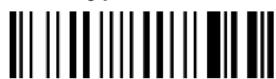
- Read the Bind code to pair the Gryphon™ BT to the OM-Gryphon™ BT cradle.
The cradle will refuse connection to any previously bound reader. It is however, advised to unbind any previously bound reader.

The blue LED on the Gryphon™ BT will blink; the reader is ready to be positioned onto the cradle.
- Firmly position the reader onto the OM-Gryphon™ BT cradle within 4 seconds, a beep will be emitted, signaling that the OM-Gryphon™ BT cradle has been paired to the Gryphon™ BT.

Wait for a series of beeps (three sequences of tones separated by a pause) indicating Bluetooth connection.
- Configure the OM-Gryphon™ BT cradle. Refer to par. 3.2.1, par. 3.2.2, par. 3.2.3, or par. 3.2.4 depending on the interface selection code required for your application.
3.2.1 USB Interface Selection

The USB interface is compatible with:
Windows 98 (and later) IBM POS for Windows Mac OS 8.0 (and later) 4690 Operating System
USB START-UP
As with all USB devices, upon connection, the Host performs several checks by communicating with the OM-Gryphon™ BT. Before the OM-Gryphon™ BT is ready, the correct USB driver must be loaded.
For all systems, the correct USB driver for the default USB-KBD interface is included in the Host Operating System and will either be loaded automatically or will be suggested by the O.S. and should therefore be selected from the dialog box (the first time only).
You can now read codes with the associated Gryphon™ BT reader. At this point you can read the USB interface configuration code according to your application. Load drivers from the O.S. (if requested). When configuring the USB-COM interface, the relevant files and drivers must be installed from the USB Device Installation software which is available on the CD-ROM and can also be downloaded from the web site: http://www.scanning.datalogic.com.
The OM-Gryphon™ BT is ready.
![graph TD A["Connect OM-Gryphon™ BT to Host"] --> B["Load drivers (if requested)"] B --> C["Select desired USB interface code (USB-KBD is default)"] C --> D["Load drivers (if requested)"] D --> E["Read test codes. OM-Gryphon™ BT is READY"]](/content/2026/07/1509843/images/e4abf332e012d790189dd03ebfcde24102d28d61a510cbe57222d78053790243.jpg)
Successive start-ups will automatically recognize the previously loaded drivers.
USB

* When configuring USB-COM, the relevant files and drivers must be installed from the USB Device Installation software which is available on the CD-ROM and can also be downloaded from the web site (see http://www.scanning.datalogic.com).
3.2.2 RS232 Interface Selection
![graph LR A["Host"] -->|RS232| B["OM-Gryphon™ BT"] B --> C["Computer with keyboard"]](/content/2026/07/1509843/images/708ec88fda2d570cd350bfe30a225735e49442e2c3f14f05175bc84ea302bedd.jpg)
- Read the OM-Gryphon™ BT restore default code:
Restore OM-Gryphon™ BT Default

- Read the interface selection code for your application:

POS TERMINALS


For POS terminal default settings refer to par. 5.10.
3.2.3 WEDGE Interface Selection

- Read the OM-Gryphon™ BT restore default code:
Restore OM-Gryphon™ BT Default

- Read the interface selection code for your application:
WEDGE
IBM AT or PS/2 PCs

IBM XT


IBM
Terminals
31xx,
To select the interface for these IBM Terminals, read the correct key transmission code. Select the keyboard type if necessary (default = advanced keyboard).
KEY TRANSMISSION MODE

KEYBOARD TYPE


ALT MODE
The following interface selection allows barcodes sent to the PC to be interpreted correctly independently from the Keyboard Nationality used.
You do not need to make a Keyboard Nationality selection.
(default = Num Lock Unchanged)
Make sure the Num Lock key on your keyboard is ON.


DIGITAL TERMINALS

APPLE

3.2.4 PEN Emulation Interface Selection

- Read the OM-Gryphon™ BT restore default code:
Restore OM-Gryphon™ BT Default

- Read the interface selection code for your application:
PEN EMULATION

3.3 SETTING UP GRYPHON™ BT WITH BLUETOOTH ® DEVICE
During typical operation a physical radio channel is shared by a group of devices that are synchronized to a common clock and frequency hopping pattern. One device provides the synchronization reference and is known as the Master. All other devices are known as Slaves. A group of devices synchronized in this fashion form a piconet.
Most Bluetooth ® devices can be both Master or Slave. The Master will be the first unit to initiate the connection (page procedure).
Some devices can only be Slaves (i.e. printers). They can only wait for a Bluetooth ® Master device to initiate a connection with them.
Gryphon™ BT can be either Master or Slave. As Master it can initiate a connection with only one Slave device.

NOTE
Gryphon™ BT uses the Serial Port Profile (SPP) for communication, creating an RS232 cable replacement. It is also possible to emulate a Wedge connection by means of the Wedge Emulation Utility provided on the CD-ROM. When using the Wedge Emulation Utility, it is advised to correctly set the terminators depending on the expected format for the program in which the data will be collected.
Follow one of the following two procedures to set up Gryphon™ BT as Slave or as Master according to your application.
The blue LED and / or the beeper always indicate the reader radio connection status (see also the Reader Status table, at page 163):
- the radio connection is signaled by the blue LED through a single blink at regular intervals, while if the reader radio is disconnected the LED emits two short blinks at regular intervals;
- during the initialization procedure, if the radio connection attempt is successful, the reader emits four ascending tones;
- the radio disconnection is signaled by four descending tones.
3.3.1 Setup for Gryphon™ BT as Slave
Once set as Slave, a Gryphon™ BT reader requires no particular configuration for communication, however some radio parameters can be set to increase system performance and data transmission security. At startup the reader can only wait for the Master to initialize the radio communication.
The following is a general procedure recommended for Gryphon™ BT Slave applications:
- Power up the remote Bluetooth ® Master device (example Laptop or PC).
- Power up the Gryphon™ BT reader within radio range (10 meters).
Any modifications to the radio configuration should be made at this time before the radio connection takes place. - From the remote Bluetooth ® Master device, execute the Discovery procedure, (according to the procedure given in the documentation of the Bluetooth ® Master device), to recognize the Gryphon ™ BT reader(s) within radio range.
- Check that "Gryphon BTx00 " is shown among the discovered devices.
- Request to open an SPP connection with Gryphon™ BT, making sure to disable any required PIN and/or pairing parameters. Gryphon™ BT is always discoverable and connectable without any required PIN.

NOTE
If the PIN of the Bluetooth ® Master device cannot be disabled, use the PIN "1234". The Gryphon ™ BT Slave will emit four ascending tones indicating radio connection.
After the Gryphon™ BT reader(s) indicate radio connection (see also the Reader Status Table, at page 163), you can start sending barcodes.
The following figure shows an example Gryphon™ BT Slave application.

Figure 1 - Gryphon™ BT Slave Application
If the Master Bluetooth ® device can support a piconet, the communication can be established with up to 7 seven Slave readers at the same time.
To configure the Gryphon™ BT as Slave follow the given procedure.
1.
Restore Gryphon™ BT Default

2.
Set Gryphon™ BT as Slave

YOUR READER IS NOW READY TO BE DISCOVERED (CONNECTED VIA RADIO) BY A BLUETOOTH ® MASTER DEVICE AND READ BARCODES.
3.3.2 Setup for Gryphon™ BT as Master
Once set as Master, a Gryphon™ BT reader must be configured with the address of the Slave device to which it wants to communicate.
By default, at startup the reader initializes the communication with the Slave. If the connection is successful, the reader can send barcodes to the Slave device. Radio connections can also be managed manually by disabling the automatic connection parameters (described in pars. 5.8.3, 5.8.4) and reading the connection barcodes in par. 6.1.
During the request of radio connection or disconnection with a remote Bluetooth ® Slave device, the reader emits a series of ticks and short blinks of the blue LED.
The following figure shows an example Gryphon™ BT Master application.

Figure 2 - Gryphon™ BT Master Application
To configure the Gryphon™ BT as Master follow the given procedure.
Note: for the hexadecimal character selection of step 4, use the Hex/Numeric table in appendix C.


3.
Enter Configuration

4.
Set Remote Bluetooth® Device Address (slave)

12 characters (in HEX format)
for the remote Bluetooth ® device address specified in each Bluetooth ® device.
5.
Exit and Save Configuration

6.
Request Radio Connection with Slave

If the connection is not successful, you can attempt a connection manually by double-clicking the reader trigger.
YOUR READER IS NOW CONFIGURED TO READ BARCODES USING THE DEFAULT VALUES.
4 CONFIGURATION
4.1 CONFIGURATION METHODS
4.1.1 Reading Configuration Barcodes
If you wish to change the default settings, this manual provides complete configuration of your reader in an easy way.
To configure your reader:
1) Read the Enter Configuration code ONCE, available at the top of each page of configuration.
2) Modify the desired parameters in one or more sections following the procedures given for each group. If arguments are required with a command, you can read additional barcode labels (typically digits) from Appendix C.
3) Read the Exit and Save Configuration code ONCE, available at the top of each page of configuration.
Reference notes describing the operation of the more complex parameters are given in chapter 5.
4.1.2 Sending Configuration Strings from Host
An alternative configuration method is provided in Appendix A using the OM-Gryphon™ BT or C-Gryphon connected to the Host via the RS232 interface. Batch files containing the desired parameter settings can be prepared to configure devices quickly and easily. This method is particularly useful when many devices need to be configured with the same settings.
4.2 DEFAULT SETTINGS
USB
DATA FORMAT: code identifier disabled, no field adjustment, code length not transmitted, character replacement disabled, address stamping = disabled, address delimiter = disabled.
USB KEYBOARD: USA keyboard, inter-character and inter-code delays disabled.
USB COM: no handshaking, delay disabled, rx timeout 5 sec., ack/nack disabled, serial trigger lock disabled.
Default Headers and Terminators for each USB mode:
- USB-KBD: no header, terminator = ENTER
- USB-KBD-ALT-MODE: no header, terminator = CR
- USB-COM: no header, terminator = CR-LF
- USB-IBM-TABLE TOP: not applicable
- USB-IBM-HAND HELD: not applicable
RS232
Standard
9600 baud, no parity, 8 data bits, 1 stop bit, no handshaking, delay disabled, rx timeout 5 sec., ack/nack disabled, serial trigger lock disabled;
DATA FORMAT: code identifier disabled, no field adjustment, code length not transmitted, no header, terminator = CR-LF, character replacement disabled, address stamping = disabled, address delimiter = disabled
Nixdorf Mode A
9600 baud, parity odd, 8 data bits, 1 stop bit, handshaking hardware (RTS/CTS), delay disabled, rx timeout 9.9 sec., ack/nack disabled, serial trigger lock disabled;
DATA FORMAT: code identifier enabled, no field adjustment, code length not transmitted, no header, terminator = CR, character replacement disabled, address stamping = disabled, address delimiter = disabled
Fujitsu
9600 baud, no parity, 8 data bits, 1 stop bit, no handshaking, delay disabled, rx timeout 2 sec., ack/nack disabled, serial trigger lock disabled;
DATA FORMAT: code identifier enabled, no field adjustment, code length not transmitted, no header, terminator = CR, character replacement disabled, address stamping = disabled, address delimiter = disabled
ICL
9600 baud, parity even, 8 data bits, 1 stop bit, handshaking RTS always on, delay disabled, rx timeout 9.9 sec., ack/nack disabled, serial trigger lock disabled;
DATA FORMAT: code identifier enabled, no field adjustment, code length not transmitted, no header, terminator = CR, character replacement disabled, address stamping = disabled, address delimiter = disabled
| WEDGEUSA keyboard, caps lock off, caps lock auto-recognition enabled, num lock unchanged, inter-character and inter-code delays disabled,DATA FORMAT: code identifier disabled, no field adjustment, code length not transmitted, no header, terminator = ENTER, character replacement disabled, address stamping = disabled, address delimiter = disabled | |
| PEN EMULATIONinterpret mode, conversion to code 39 disabled, output level normal, idle level normal, minimum output pulse 600 μs, overflow medium, inter-block delay disabled | |
| DATA FORMAT for BT DEVICEcode identifier disabled, field adjustment disabled, code length tx not transmitted, character replacement disabled, address stamping = disabled, address delimiter = disabled, no header, terminator = CR-LF. | |
| POWER SAVEmaximum scan rate | |
| READING PARAMETERShardware trigger, trigger active level, no timeout, Flash On = 1 sec, Flash Off = 0.6 sec, one read per cycle, safety time 0.5 sec, beeper intensity high, tone 2, beeper type monotone, beeper length short, good read spot duration medium. | |
| DECODING PARAMETERSink spread enabled, overflow control enabled, interdigit control enabled, Puzzle SolverTMdisabled, decoding safety = one read. | |
| CODE SELECTION | |
| enabled codes | |
| BT200 | Code PDF417 |
| BT100BT200 | EAN 8/EAN 13 / UPC A/UPC E without ADD ONcheck digit transmitted, no conversionsInterleaved 2/5check digit control and transmission, variable length code; 4-99 charactersStandard Code 39no check digit control, variable length code; 1-99 charactersCode 128, variable length code; 1-99 characters |
| disabled codes | |
| BT100 | EAN 128, ISBT128, Code 93, Codabar, pharmaceutical codes, MSI,Plessey, Telepen, Delta IBM, Code 11, Code 16K, Code 49, RSS family. |
| BT200 | EAN 128, ISBT128, Code 93, Codabar, pharmaceutical codes, RSS family |
| ADVANCED FORMATTING PARAMETERS | |
| concatenation disabled, no advanced formats defined, Zebra printer formatting = disabled. | |
| RADIO PARAMETERS | |
| ALL CONFIGURATIONS: radio protocol timeout = 3 seconds, transmission retry =none, power-off timeout = 4 hours, beeper control for radio response = gooddecode and good reception. | |
| GRYPHONTM BT WITH OM-GRYPHONTM BT: encryption disabled, batch modedisabled. | |
| GRYPHONTM BT WITH BT DEVICE: no ACK/NACK protocol nor frame packing,user-friendly name = "Gryphon BTx00", auto-connection enabled, auto-reconnection enabled. | |
4.3 CHANGING DEFAULT SETTINGS
Once your reader is setup, you can change the default parameters to meet your application needs. Refer to the preceding chapter for initial configuration in order to set the default values and select the interface for your application.
In this manual, the configuration parameters are divided into logical groups making it easy to find the desired function based on its reference group.
The first four groups are for Standard Interface parameter configuration when using the OM-Gryphon™ BT cradle:
- USB
- RS232
- WEDGE
- PEN EMULATION
The following parameter groups are common to all applications:
DATA FORMAT parameters regard the messages sent to the Host system for all interfaces except Pen Emulation.
POWER SAVE manages overall current consumption in the reading device.
READING PARAMETERS control various operating modes and indicator status functioning.
DECODING PARAMETERS maintain correct barcode decoding in certain special reading conditions.
CODE SELECTION parameters allow configuration of a personalized mix of codes, code families and their options.
ADVANCED FORMATTING PARAMETERS allow code concatenation and advanced formatting of messages towards the Host. It cannot be used with Pen Emulation.
RADIO PARAMETERS allow configuration of radio control parameters.
USB PARAMETERS
USB-COM
- Handshaking, ACK/NACK Protocol, Inter-character Delay, Rx Timeout, Serial Trigger Lock
USB-KBD
- Keyboard Nationality, Inter-character Delay, Inter-code Delay, Keyboard Character Assignment
- Read the Enter Configuration code ONCE, available at the top of each page.
- Read configuration codes from the desired groups.
= Read the code and follow the procedure given
◆ = Default value
- Read the Exit and Save Configuration code ONCE, available at the top of each page.
HANDSHAKING
◆ disable

hardware (RTS/CTS)

software (XON/XOFF)

RTS always ON

See par. 5.1.1 for details.
ACK/NACK PROTOCOL
◆ disable

enable

See par. 5.1.2 for details.
INTER-CHARACTER DELAY
delay between characters transmitted to Host

Read 2 numbers from the table where:
00 = DELAY disabled
01-99 = DELAY from 1 to 99 milliseconds
◆ delay disabled
Rx TIMEOUT
timeout control in reception from Host

Read 2 numbers from the table where:
00 = TIMEOUT disabled
01-99 = TIMEOUT from .1 to 9.9 seconds
◆ rx timeout 5 seconds
See par. 5.1.3 for details.
SERIAL TRIGGER LOCK
◆ disabled

enable and select characters

Read 2 characters from the Hex/Numeric table in the range 00-FE where:
- First Character enables device trigger
– Second Character inhibits device trigger until the first character is received again.
KEYBOARD NATIONALITY
Not Available for USB-KBD-ALT-MODE Interface
This parameter default value is restored through the Interface Selection code and not Restore Default.

INTER-CHARACTER DELAY
delay between characters transmitted to Host

Read 2 numbers from the table where:
00 = DELAY disabled
01-99 = DELAY from 1 to 99 milliseconds
◆ delay disabled
INTER-CODE DELAY
delay between codes transmitted to Host

Read 2 numbers from the table where:
00 = DELAY disabled
01-99 = DELAY from 1 to 99 seconds
◆ delay disabled
KEYBOARD CHARACTER ASSIGNMENT
Character
Assignment

① Read the character assignment code above:
② Read the Hex value of the ASCII character you want to assign, (the character in the barcode), from the codes in the Hex/Numeric Table. Valid values are from 00 to FD. See the Character to Hex Conversion Table for reference in appendix C.
③ Read one of the Assignment codes below:

cancel code assignment
(read the Exit & Save Configuration code at the top of this page)

assign character to single key or 2-key sequence
(go to step 4)

assign character to 4-key sequence
(go to step 4)
⑤ Read the three numeric values for the scancode of the key to associate with the new character. Repeat steps 4 and 5 for a 4-key sequence.
⑥ Read the Exit & Save Configuration barcode at the top of this page.
Examples
- To transmit the i character to the host as the sequence of keys Shift 0.
The scancode for the 0 key = 045
Therefore the command:
 |  |  |  |
| BF | |||
| Character Assignment hex value of character in barcode to be transmitted to Host | assign character to 2-key sequence | ||


Shift key modifier
i key scancode
- To transmit the A character to the host as the sequence of keys Ctrl' Shift A.
The scancode for the * key = 00E
The scancode for the A key = 01C
Therefore the command:
 |  |  |  |
| Character Assignment h | C0 | assign character to 4-key sequence | |
| hex value of character in barcode to be transmitted to Host | |||


Shift key modifier
A key scancode
RS232 PARAMETERS
BAUD RATE
PARITY
DATA BITS
- STOP BITS
- HANDSHAKING
-
- ACK/NACK PROTOCOL
-
INTER-CHARACTER DELAY
Rx TIMEOUT
- SERIAL TRIGGER LOCK
-
- Read the Enter Configuration code ONCE, available at the top of each page.
- Read configuration codes from the desired groups.
= Read the code and follow the procedure given
◆ = Default value
- Read the Exit and Save Configuration code ONCE, available at the top of each page.
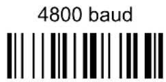
BAUD RATE




PARITY
none

even parity

odd parity

DATA BITS
7 bits

◆ 8 bits

9 bits

STOP BITS
◆ 1 stop bit

2 stop bits

HANDSHAKING
◆ disable

hardware (RTS/CTS)

software (XON/XOFF)

RTS always ON

See par. 5.1.1 for details.
ACK/NACK PROTOCOL
◆ disable

enable

See par. 5.1.2 for details.
INTER-CHARACTER DELAY
delay between characters transmitted to Host

Read 2 numbers from the table where:
00 = DELAY disabled
01-99 = DELAY from 1 to 99 milliseconds
◆ delay disabled
Rx TIMEOUT
timeout control in reception from Host

Read 2 numbers from the table where:
00 = TIMEOUT disabled
01-99 = TIMEOUT from .1 to 9.9 seconds
◆ rx timeout 5 seconds
See par. 5.1.3 for details.
SERIAL TRIGGER LOCK
◆ disabled

enable and select characters

Read 2 characters from the Hex/Numeric table in the range 00-FE where:
- First Character enables device trigger
– Second Character inhibits device trigger until the first character is received again.
WEDGE PARAMETERS
KEYBOARD NATIONALITY
CAPS LOCK
CAPS LOCK
AUTO-RECOGNITION
- NUM LOCK
INTER-CHARACTER DELAY
INTER-CODE DELAY
KEYBOARD CHARACTER
ASSIGNMENT
-
Read the Enter Configuration code ONCE, available at the top of each page.
-
Read configuration codes from the desired groups.
= Read the code and follow the procedure given
◆ = Default value
- Read the Exit and Save Configuration code ONCE, available at the top of each page.
KEYBOARD NATIONALITY
This parameter default value is restored through the Interface Selection code and not Restore Default.

The Japanese Keyboard Nationality selection is valid only for IBM AT compatible PCs.
Japanese

CAPS LOCK
◆ caps lock OFF

caps lock ON

Select the appropriate code to match your keyboard caps lock status.
Note: Caps lock manual configuration is ignored when Caps Lock Auto-Recognition is enabled.
For PC Notebook interface selections, the caps lock status is automatically recognized, therefore this command is not necessary.
CAPS LOCK AUTO-RECOGNITION (IBM AT COMPATIBLE ONLY)
disable

◆ enable

Num Lock
toggle num lock

◆ num lock unchanged

This selection is used together with the Alt Mode interface selection for AT or Notebook PCs.
It changes the way the Alt Mode procedure is executed, therefore it should be set as follows:
- if your keyboard Num Lock is normally on use num lock unchanged
- if your keyboard Num Lock is normally off use toggle num lock
In this way the device will execute the Alt Mode procedure correctly for your application.
INTER-CHARACTER DELAY
delay between characters transmitted to Host

Read 2 numbers from the table where:
00 = DELAY disabled
01-99 = DELAY from 1 to 99 milliseconds
◆ delay disabled
INTER-CODE DELAY
delay between codes transmitted to Host

Read 2 numbers from the table where:
00 = DELAY disabled
01-99 = DELAY from 1 to 99 seconds
◆ delay disabled
KEYBOARD CHARACTER ASSIGNMENT
Character

Assignment
① Read the character assignment code above:
② Read the Hex value of the ASCII character you want to assign, (the character in the barcode), from the codes in the Hex/Numeric Table. Valid values are from 00 to FD. See the Character to Hex Conversion Table for reference in appendix C.
③ Read one of the Assignment codes below:

cancel code assignment
(read the Exit & Save Configuration code at the top of this page)

assign character to single key or 2-key sequence
(go to step 4)

assign character to 4-key sequence
(go to step 4)
⑤ Read the three numeric values for the scancode of the key to associate with the new character. Repeat steps 4 and 5 for a 4-key sequence.
⑥ Read the Exit & Save Configuration barcode at the top of this page.
Determining a Key's Scancode (for Wedge interface only)
Since scancode keymaps are not readily available for all the different supported keyboards, a Return Scancode command is provided. To determine the scancode of the desired character for your keyboard; connect and configure your barcode reader to the desired host device, read the code below and press the key. The scancode of the pressed key will be sent to the host and the reader exits this mode. Repeat the procedure to determine other scancodes.

Return Scancode

NOTE
The reader will signal an incomplete read tone. This is normal and not an error. Proceed to press a keyboard key to determine the scancode.
Examples
- To transmit the character to the host as the sequence of keys Shift 0.
The scancode for the 0 key = 045
Therefore the command:
 |  |  |  |
| BF | |||
| Character Assignment h | ex value of character in barcode to be transmitted to Host | assign character to 2-key sequence | |


Shift key modifier
key scancode
- To transmit the A character to the host as the sequence of keys Ctrl' Shift A.
The scancode for the * key = 00E
The scancode for the A key = 01C
Therefore the command:
 |  |  |  |
| Character Assignment hex value of character in barcode to be transmitted to Host | assign character to 4-key sequence | ||


Ctrl key modifier
00E
'key scancode


Shift key modifier
01C
A key scancode
PEN EMULATION
OPERATING MODE
MINIMUM OUTPUT PULSE
CONVERSION TO CODE 39
OVERFLOW
OUTPUT LEVEL
IDLE LEVEL
INTER-BLOCK DELAY
- Read the Enter Configuration code ONCE, available at the top of each page.
-
Read configuration codes from the desired groups.
= Read the code and follow the procedure given
◆ = Default value -
Read the Exit and Save Configuration code ONCE, available at the top of each page.
The operating mode parameters are complete commands and do not require reading the Enter and Exit configuration codes.
OPERATING MODE
◆ interpret mode

Interprets commands without sending them to the decoder.
transparent mode

Sends commands to the decoder without interpreting them.
MINIMUM OUTPUT PULSE
high resolution code emulation


low resolution code emulation


See par. 5.2.1 for details.
CONVERSION TO CODE 39
◆ disable conversion to Code 39

Transmits codes in their original format.
enable conversion to Code 39

Converts codes read into Code 39 format.
See par. 5.2.2 for details.
OVERFLOW
narrow

◆ medium

wide

See par. 5.2.3 for details.
OUTPUT LEVEL
◆ normal
(white = logic level 0)

inverted
(white = logic level 1)

See par. 5.2.4 for details.
IDLE LEVEL
normal
(black level)

inverted
(white level)

See par. 5.2.4 for details.
INTER-BLOCK DELAY
delay between character blocks transmitted to Host

Read 2 numbers from the table where:
00 = DELAY disabled
01-99 = DELAY from .1 to 9.9 seconds
◆ delay disabled
See par. 5.2.5 for details.
DATA FORMAT
NOT FOR PEN INTERFACES
CODE IDENTIFIER
CUSTOM CODE IDENTIFIER
HEADER
TERMINATOR
FIELD ADJUSTMENT
FIELD ADJ. CHARACTER
CODE LENGTH TX
CHARACTER REPLACEMENT
ADDRESS STAMPING
ADDRESS DELIMITER
- Read the Enter Configuration code ONCE, available at the top of each page.
- Read configuration codes from the desired groups.
= Read the code and follow the procedure given
◆ = Default value
- Read the Exit and Save Configuration code ONCE, available at the top of each page.
DATA FORMAT
| CODE IDENTIFIER TABLE | |||
| CODE AIM STANDARD | DATALOGIC | STANDARD Custom | |
| 2/5 interleaved ]I y | N | ||
| 2/5 industrial ]X y P | |||
| 2/5 normal 5 bars ]S y O | |||
| 2/5 matrix 3 bars ]X y Q | |||
| EAN 8 ]E 4 A | |||
| EAN 13 ]E 0 B | |||
| UPC A ]X y C | |||
| UPC E ]X y D | |||
| EAN 8 with 2 ADD ON | ]E 5 | J | |
| EAN 8 with 5 ADD ON | ]E 6 K | ||
| EAN 13 with 2 ADD ON | ]E 1 | L | |
| EAN 13 with 5 ADD ON | ]E 2 | M | |
| UPC A with 2 ADD ON | ]X y F | ||
| UPC A with 5 ADD ON | ]X y G | ||
| UPC E with 2 ADD ON | ]X y H | ||
| UPC E with 5 ADD ON | ]X y | I | |
| Code 39 | ]A y V | ||
| Code 39 Full ASCII | ]A y | W | |
| CODABAR | ]F y | R | |
| ABC CODABAR | ]X y S | ||
| Code 128 | ]C y T | ||
| EAN 128 | ]C y | k | |
| ISBT 128 | ]C4 | f | |
| Code 93 | ]G y U | ||
| CIP/39 | ]X y | Y | |
| CIP/HR | ]X y | e | |
| Code 32 | ]X y X | ||
| MSI | ]M y | Z | |
| Plessey Standard | ]P 0 | a | |
| Plessey Anker | ]P 1 | o | |
| Telepen | ]X 0 | d | |
| Delta IBM | ]X 0 | c | |
| Code 11 | ]H y | b | |
| Code 16K | ]K 0 | p | |
| Code 49 | ]T y | q | |
| RSS Expanded Linear and Stacked | ]e 0 | t | |
| RSS Limited | ]e 0 | v | |
| RSS 14 Linear and Stacked | ]e 0 | u | |
| PDF417 | ]L 0 | r | |
DATA FORMAT
- AIM standard identifiers are not defined for all codes: the X identifier is assigned to the code for which the standard is not defined. The y value depends on the selected options (check digit tested or not, check digit tx or not, etc.).
- When customizing the Datalogic Standard code identifiers, 1 or 2 identifier characters can be defined for each code type. If only 1 identifier character is required, the second character must be selected as FF (disabled).
- The code identifier can be singly disabled for any code by simply selecting FF as the first identifier character.
- Write in the Custom character identifiers in the table above for your records.
CODE IDENTIFIER
◆ disable

Datalogic standard

AIM standard

custom

CUSTOM CODE IDENTIFIER
define custom code identifier(s)

① Read the above code.
(Code Identifiers default to Datalogic standard, see table on previous page).
② Select the code type from the code table in Appendix B for the identifier you want to change.
③ You can define 1 or 2 identifier characters for each code type. If only 1 identifier character is required, the second character must be selected as FF (disabled). Read the hexadecimal value corresponding to the character(s) you want to define as identifiers for the code selected in step ②: valid characters are in the range 00-FD.
Example: To define Code 39 Code Identifier = @

HEADER
no header

one character header

two character header

three character header

four character header

five character header

six character header

seven character header

eight character header

After selecting one of the desired Header codes, read the character(s) from the HEX table. Valid characters are in the range 00-FE.
Example:
four character header

+ 41 + 42 + 43 + 44 = Header ABCD
For more details see par. 5.3.1.
TERMINATOR
no terminator

one character terminator

two character terminator

three character terminator

four character terminator

five character terminator

six character terminator

seven character terminator

eight character terminator

After selecting one of the desired Header codes, read the character(s) from the HEX table. Valid characters are in the range 00-FE.
Example:
two character terminator

+ 0D + 0A = Terminator CR LF
For more details see par. 5.3.1.
FIELD ADJUSTMENT
◆ disable field adjustment

Field adjustment allows a number of characters n, to be added to or subtracted from the barcode read. The adjustment can be different for each enabled code type. To define the field adjustment:
① Read the enable field adjustment code:
enable field adjustment

② Select the code type from the Code Identifier Table in Appendix B.
③ Select the type of adjustment to perform:
right addition

left addition

right deletion

left deletion

④ Read a number in the range 01 - 32 from the Hex/Numeric Table to define how many characters to add or delete:
Conditions:
- Adjustment is only performed on the barcode data, the Code Identifier and Code Length Transmission fields are not modified by the field adjustment parameter.
- If the field setting would subtract more characters than exist in the barcode, the subtraction will take place only to code length 0.
- You can set up to a maximum of 10 different field adjustments on the same barcode family or on different barcode families.
Example: To add 4 characters to the right of Standard Code 39 Codes:

FIELD ADJUSTMENT CHARACTER
① Read the field adjustment character code:
field adjustment character

② Read the hexadecimal value corresponding to the character you want to use for field adjustment. Valid characters are in the range 00-FE.
Example:
To define the field adjustment character = A:

CODE LENGTH TX
◆ code length not transmitted

code length transmitted in variable-digit format

code length transmitted in fixed 4-digit format

The code length is transmitted in the message after the Headers and Code Identifier characters. The code length is calculated after performing any field adjustment operations.
CHARACTER REPLACEMENT
◆ disable character replacement

This parameter allows up to three characters to be replaced from the barcode read. These substitutions are stored in memory. To define each character replacement:
① Read one of the following character replacement codes:
first
character replacement

second character replacement

third
character

② From the Code Identifier Table in Appendix B, read the Code Identifier for the desired code family.
0 = character replacement will be effective for all code families.
③ From the Hex/Numeric Table read two characters corresponding to the Hex value (00-FE) which identifies the character to be replaced.
④ From the Hex/Numeric Table read two characters corresponding to the Hex value (00-FE) which identifies the new character.
FF = the character to be replaced will be substituted with no character, that is, it will be removed from the code.
Example:
The following strings define:
- First Character Replacement: substitution in Code 39 barcodes of all occurrences of the 0 character with the 1 character.
- Second Character Replacement: substitution in Code 39 barcodes of all occurrences of the A character with the B character.
first character replacement
Code 39
ASCII characters corresponding to the HEX value for character 0
ASCII characters corresponding to the HEX value for character 1


- 30 + 31
For Code 39 codes containing the string "0123", the contents transmitted will be "1123".


- 41 + 42
ASCII characters corresponding to the HEX value for character A
ASCII characters corresponding to the HEX value for character B
For Code 39 codes containing the string "ABCD", the contents transmitted will be "BBCD".
ADDRESS STAMPING
◆ disable reader address stamping

enable reader address stamping

See par. 5.3.2 for details.
ADDRESS DELIMITER
◆ disable reader address delimiter

enable reader address delimiter and select characters

Read 2 HEX characters in the range 00-FE.
See par. 5.3.3 for details.
POWER SAVE
©
SCAN RATE
©
-
Read the Enter Configuration code ONCE, available at the top of each page.
-
Read configuration codes from the desired groups.
◆ = Default value
- Read the Exit and Save Configuration code ONCE, available at the top of each page.
SCAN RATE
quarter

half

◆ maximum

A lower scan rate reduces power consumption but can lengthen reading response time.
READING PARAMETERS
Good Read Spot Duration
- Read the Enter Configuration code ONCE, available at the top of each page.
- Read configuration codes from the desired groups.
= Read the code and follow the procedure given
◆ = Default value
- Read the Exit and Save Configuration code ONCE, available at the top of each page.
HAND-HELD OPERATION
◆ hardware trigger

software trigger

hardware trigger ready

automatic

Selections other than Hardware Trigger constantly consume battery power.
For Automatic operation, the Safety Time parameter is forced to no code consecutive reading (00).
See par. 5.4.1 for details
STAND OPERATION
hardware trigger

software trigger

◆ automatic

Selections other than Hardware Trigger constantly consume battery power.
For Automatic operation, the Safety Time parameter is forced to no code consecutive reading (00).
See par. 5.4.1 for details
HARDWARE TRIGGER SIGNAL
◆ trigger active level

trigger active pulse

See par. 5.4.2 for details
TRIGGER-OFF TIMEOUT
trigger-off timeout

Read 2 numbers in the range 00-99:
00 = disables the trigger-off timeout
01-99 = corresponds to a max. 99-sec. delay after the trigger press to allow the reader to turn off automatically.
◆ trigger-off timeout disabled
See par. 5.4.3 for details.
FLASH MODE
"FLASH" ON duration

"FLASH" OFF duration

Read 2 numbers in the range 01-99:
01 to 99 = from .1 to 9.9 seconds.
◆ Flash-ON = 1 sec. Flash-OFF = 0.6 sec
READS PER CYCLE
◆ one read per cycle

multiple reads per cycle

See par. 5.4.4 for details.
SAFETY TIME
safety time

Limits same code consecutive reading.
Read 2 numbers in the range 00-99:
00 = no same code consecutive reading until reader is removed (no decoding) for at least 400 ms.
01-99 = timeout from .1 to 9.9 seconds before a consecutive read on same code.
◆ safety time = 0.5 sec
See par. 5.4.5 for details.
BEEPER INTENSITY
beeper off *

low intensity

medium intensity

◆ high intensity

* This sets the beeper OFF for data entry, while for all other beeper signals it has the meaning “very low intensity”. The Beeper Intensity parameter is effective for all operating conditions described in par. 8.3.
BEEPER TONE

BEEPER TYPE


BEEPER LENGTH
long
Enter Configuration Exit and Save Configuration

READING PARAMETERS


◆ short

PDF DECODING RECOGNITION INTENSITY
◆ low

high

GOOD READ SPOT DURATION
disable

short

◆ medium

long

DECODING PARAMETERS
INK SPREAD
OVERFLOW CONTROL
INTERDIGIT CONTROL
DECODING SAFETY
PUZZLE SOLVER TM

CAUTION
Before changing these parameter values read the descriptions in par. 5.5.
-
Read the Enter Configuration code ONCE, available at the top of each page.
-
Read configuration codes from the desired groups.
◆ = Default value
- Read the Exit and Save Configuration code ONCE, available at the top of each page.
INK SPREAD
disable

◆ enable

See par. 5.5.1 for details.
OVERFLOW CONTROL
disable

◆ enable

See par. 5.5.2 for details.
INTERDIGIT CONTROL
disable

◆ enable

See par. 5.5.3 for details.
DECODING SAFETY
◆ one read

(decoding safety disabled)
two reads
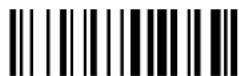
three reads

four reads

Required number of good reads before accepting code.
In the case of damaged or poorly printed codes, this parameter allows reading multiple parts of the single code to reconstruct it.
To read codes using this technology, simply move the reader over the code so that each line of the code is scanned.
Conditions:
- This parameter is only valid for the following codes:
| EAN 8 without Add-on | EAN 13 without Add-on | UPC A without Add-on |
| Code 128 Code 39 | ||
• For Code 39, Check digit control without transmission is forced.
- PuzzleSolver™ is disabled when code ISBT 128 is enabled.
CODE SELECTION
| ◎ | EAN/UPC FAMILY | ◎ |
| ◎ | 2/5 FAMILY | ◎ |
| ◎ | CODE 39 FAMILY | ◎ |
| ◎ | CODE 128 FAMILY | ◎ |
| ◎ | CODABAR FAMILY | ◎ |
| ◎ | CODE 93 | ◎ |
| ◎ | MSI | ◎ |
| ◎ | PLESSEY | ◎ |
| ◎ | TELEPEN | ◎ |
| ◎ | DELTA IBM | ◎ |
| ◎ | CODE 11 | ◎ |
| ◎ | CODE 16K | ◎ |
| ◎ | CODE 49 | ◎ |
| ◎ | RSS CODES | ◎ |
| ◎ | PDF417 | ◎ |
| PDF READERS ONLY |
- Read the Enter Configuration code ONCE, available at the top of each page.
- Read configuration codes from the desired groups.
= Read the code and follow the procedure given
◆ = Default value
- Read the Exit and Save Configuration code ONCE, available at the top of each page.
DISABLES ALL CODE FAMILIES


NOTE
The reader allows up to 5 code selections. This does not limit the number of CODES enabled to 5, as it depends on the code family.
SINGLE SELECTIONS =
• ONE combination code from the EAN family
- ONE code from the 2/5 family
Example
5 code selections: 1. 2/5 Interleaved
- 2/5 Industrial
- Code 128 + EAN 128
- Code 39 Full ASCII + Code 32
- UPC A/UPC E ____
In this section all SINGLE code selections are underlined and in bold.
EAN/UPC FAMILY
disable the family

① Read the desired family code
Note:
Since the EAN/UPC without ADD ON code selection is enabled by default, to correctly enable another selection, first disable the family.
EAN 8/EAN 13/UPC A/UPC E with and without ADD ON

WITHOUT ADD ON
◆ EAN 8/EAN 13/UPC A/UPC E

EAN 8/EAN 13

UPC A/UPC E

WITH ADD ON 2 AND 5
EAN 8/EAN 13/UPC A/UPC E

EAN 8/EAN 13

UPC A/UPC E

WITH ADD ON 2 ONLY
EAN 8/EAN 13

UPC A/UPC E

WITH ADD ON 5 ONLY
EAN 8/EAN 13

UPC A/UPC E

EAN/UPC CHECK DIGIT TX SELECTIONS
For each code type in this family you can choose to transmit the check digit or not
CHECK DIGIT TRANSMISSION


NO CHECK DIGIT
TRANSMISSION


CONVERSION OPTIONS
UPC E to UPC A conversion

UPC E to EAN 13 conversion

UPC A to EAN 13 conversion

EAN 8 to EAN 13 conversion

Enable only ISBN conversion

Enable only ISSN conversion

Enable both ISBN and ISSN conversion

Disable both ISBN and ISSN conversion

2/5 FAMILY
disables the family

① Read the desired family code
◆ Interleaved 2/5

Normal 2/5 (5 Bars)

Industrial 2/5 (IATA)

Matrix 2/5 (3 Bars)

The pharmaceutical code below is part of the 2/5 family but has no check digit or code length selections.
Code CIP/HR

French pharmaceutical code
② Read a check digit selection
CHECK DIGIT TABLE
no check digit control

◆ check digit control and transmission
check digit control without transmission

③ Read 4 numbers for the code length where:
- First 2 digits = minimum code length.
- Second 2 digits = maximum code length.
The maximum code length is 99 characters.
The minimum code length must always be less than or equal to the maximum.
Examples:
0199 = variable from 1 to 99 digits in the code.
1010 = 10 digit code length only.
CODE 39 FAMILY
disables the family

① Read the desired family code
② Read a check digit selection
CHECK DIGIT TABLE
◆ Standard Code 39

◆ no check digit control

Full ASCII Code 39

check digit control
and transmission

check digit control
without transmission

The pharmaceutical codes below are part of the Code 39 family but have no check digit selections.
Code CIP39

French pharmaceutical code
Code 32

Italian pharmaceutical code
CODE LENGTH (optional)
The code length selection is valid for the entire Code 39 family
Read the code + 4 numbers for the code length where:
First 2 digits = minimum code length.
Second 2 digits = maximum code length.
set code length

The maximum code length is 99 characters.
The minimum code length must always be less than or equal to the maximum.
Examples: 0199 = variable from 1 to 99 digits in the code. 1010 = 10 digit code length only.
CODE 128 FAMILY
disables the family

① Read the desired family code
◆ Code 128

control without transmission of check digit
EAN 128

control without transmission of check digit
Transmit GS Before Code
Code EAN 128 uses the ASCII
◆ disable

enable

If the
ISBT 128

Enabling ISBT 128 automatically disables Puzzle Solver™.
CODE LENGTH (optional)
The code length selection is valid for the entire Code 128 family.
Read the code + 4 numbers for the code length where:
First 2 digits = minimum code length
Second 2 digits = maximum code length
set code length

The maximum code length is 99 characters. The minimum code length must always be less than or equal to the maximum.
Examples: 0199 = variable from 1 to 99 digits in the code. 1010 = 10 digit code length only.
The length is calculated on the output string.
CODE 93
◆ disables the code

Code 93

control without transmission of check digit
CODABAR FAMILY
◆ disables the family

① Read the desired equality control code
② Read a start/stop transmission selection
START/STOP CHARACTER TRANSMISSION
Standard Codabar

no start/stop character equality control
no transmission

Standard Codabar

start/stop character equality control
transmission

The Codabar ABC code below uses a fixed start/stop character transmission selection.
Codabar ABC

no start/stop character equality control but transmission.
Codabar ABC Forced Concatenation
enable Codabar ABC with forced concatenation

non start/stop character equality control but transmission
CODE LENGTH (optional)
The code length selection is valid for the entire Codabar family
Read the code + 4 numbers for the code length where:
First 2 digits = minimum code length.
Second 2 digits = maximum code length.
set code length

The maximum code length is 99 characters.
The minimum code length must always be less than or equal to the maximum.
Examples: 0199 = variable from 1 to 99 digits in the code. 1010 = 10 digit code length only.
START/STOP CHARACTER CASE IN TRANSMISSION
The start/stop character case selections below are valid for the entire Codabar family:
transmit start/stop characters in lower case

transmit start/stop characters in upper case

MSI
◆ disables the family

Enable the code by selecting one of the check digit selections.
no check digit control

MOD10 check digit control no check digit transmission

MOD10 check digit control check digit transmission

MOD11 - MOD10 check digit control no check digit transmission

MOD11 - MOD10 check digit control check digit transmission

MOD10 - MOD10 check digit control no check digit transmission

MOD10 - MOD10 check digit control check digit transmission

PLESSEY
◆ disables the family

Enable the code by selecting one of the check digit selections.
Standard Plessey
no check digit control

check digit control check digit transmitted

check digit control check digit not transmitted

Anker Plessey
no check digit control

check digit control check digit transmitted

check digit control check digit not transmitted

TELEPEN
◆ disables the family

Enable the code by selecting one of the check digit selections.
Numeric Telepen
no check digit control

check digit control check digit transmitted

check digit control check digit not transmitted

Alphanumeric Telepen
no check digit control

check digit control check digit transmitted

check digit control check digit not transmitted

DELTA IBM
◆ disables the family

Enable the code by selecting one of the check digit selections.
no check digit control

Type 1 check digit control

Type 2 check digit control

CODE 11
◆ disables the family

Enable the code by selecting one of the check digit selections.
no check digit control

Type C check digit control check digit transmitted

Type C check digit control check digit not transmitted

Type K check digit control check digit transmitted

Type K check digit control check digit not transmitted

Type C and Type K check digit control check digits transmitted

Type C and Type K check digit control check digits not transmitted

CODE 16K
◆ disables the code

Code 16K

To read stacked codes, simply move the reader over the code so that each line of the code is scanned. During this process a series of brief "ticks" indicates that reading is proceeding correctly.
CODE 49
◆ disables the code

Code 49

To read stacked codes, simply move the reader over the code so that each line of the code is scanned. During this process a series of brief "ticks" indicates that reading is proceeding correctly.
RSS CODES
◆ disables the family

DISABLE CODE
disable RSS Expanded Linear and Stacked

disable RSS Limited

disable RSS 14 Linear and Stacked

ENABLE CODE
enable RSS Expanded Linear and Stacked

enable RSS Limited

enable RSS 14 Linear and Stacked

To read the stacked version of these codes, simply move the reader over the code so that each line of the code is scanned. During this process a series of brief "ticks" indicates that reading is proceeding correctly.
PDF417
PDF417 Readers Only
disables the code

◆ PDF417

To read stacked codes, simply move the reader over the code so that each line of the code is scanned. During this process a series of brief "ticks" indicates that reading is proceeding correctly.
ADVANCED FORMATTING
CONCATENATION
ADVANCED FORMATTING
ZEBRA PRINTER FORMATTING
ZEBRA PRINTER FORMAT FILE SELECTION

NOTE
Please follow the setup procedure carefully for these parameters.
- Read the Enter Configuration code ONCE, available at the top of page.
- Read configuration codes precisely following the numbered procedure given.
= Read the code and follow the procedure given
◆ = Default value
- Read the Exit and Save Configuration code ONCE, available at the top of page.
CONCATENATION


Permits the concatenation of two codes defined by code type and length. It is possible to set a timeout for the second code reading and to define code transmission if the timeout expires.
The order of transmission is CODE 1-CODE 2.
Define Concatenation
1
Code 1

Read the code type from the Code Identifier Table beginning in Appendix B.

Read a number in the range 01-99 from the Hex/Numeric Table.
2
Code 2
code ID

Read the code type from the Code Identifier Table beginning in Appendix B.
code length

Read a number in the range 01-99 from the Hex/Numeric Table.
3
Concatenation Result Code ID
use code 1 ID

use code 2 ID

Since you can concatenate codes from different families, you must select the Code ID character of the resulting code. The Code ID character will be sent in the output message only if it is enabled according to the Code Identifier selection (Datalogic, AIM, or Custom).
4
Concatenation Timeout
timeout

Read two numbers in the range 00 to 99
00= no timeout
01-99 = timeout from 1 to 99 seconds
ADVANCED FORMATTING

Define the timeout, which determines the valid waiting period between the two codes, in order to accept concatenation. If the timeout expires, the resulting action will be based on the following selection.
5
Transmission after Timeout
no code transmitted after timeout

only code 1 transmitted (if read) after timeout

only code 2 transmitted (if read) after timeout

either code 1 or code 2 transmitted after timeout

ADVANCED FORMATTING
Advanced formatting has been designed to offer you complete flexibility in changing the format of barcode data before transmitting it to the host system. This formatting will be performed when the barcode data meets certain criteria which you will define in the following procedure.
Up to 4 advanced code management formats can be defined and saved in memory. For each format you must complete the entire configuration procedure:
![graph TD A["Read the Enter Configuration Command"] --> B["Step 1 Begin Format Definition 1, 2, 3, or 4"] B --> C["Steps 2 - 4 Define Match Code Conditions"] C --> D["Step 5 Divide Code into Fields"] D --> E["Step 6 Define Code Fields"] E --> F["Steps 7 - 8 Add up to 2 Additional Fields"] F --> G["St…](/content/2026/07/1509843/images/c0c105fa202cfffb244a9dcbcf49267e31e8cf8e9a851585167cd64f4b12084c.jpg)
1 Begin Format Definition
begin Format 1 definition

begin Format 2 definition

begin Format 3 definition

begin Format 4 definition

2
Match
Code
match code type

Read the above code + the code type to match from the Code Identifier Table in Appendix B.
OR
any code type

3
Match
Code
match code length

Read the above code + two numbers in the range 01 to 99 for the exact code length.
OR
any code length

4
Match with Predefined Characters

match with 1 character
match with a 2-character string

match with a 3-character string

match with a 4-character string

After selecting the predefined match code, read the character(s) from the HEX table. Range of characters = 01-FE.
Example:
Match code with the 2-character predefined string = "@@".
Read
Match with a 2-character string

+ 40 + 40
AND position of first character in predefined string
ADVANCED FORMATTING

Read the above code + two numbers in the range 01 to 99 representing the character position in the code where the first character of the predefined string must be found.
Read 00 if the match string can be found in any character position.
5
Divide Code into Fields
divide code into fields

Read one number in the range 1 to 5 to divide the code into fields.
6 Define Code Fields
define code fields
Each code field length can be set by either:
a) defining a field separator character to be found in the code itself. In this case you can choose to discard the code separator character or include it as the last character of the field.
OR BY
b) specifying a specific character length up to the maximum of 99 characters.
OR BY
c) selecting the last field as variable length (if any).
You must define the same number of fields as selected in step 5, including fields that will not be transmitted.
DEFINE FIELD 1 BY: EITHER
a)
field separator

Read the field separator character from the HEX table. Range of characters = 01-FE. discard separator include separator
OR
b)
field length

Read two numbers in the range 01 to 99 to define the field length.
OR
c)
this is the last field (variable length)

AND
Field 1 Terminators
no field terminators

1 field terminator 2 field terminators


Read the field terminator character(s) from the HEX table.
Valid range of characters for all readers = 01-FE.
For readers using Wedge interface, all values from 9C to FE send the Space character.
DEFINE FIELD 2 BY: EITHER

Read the field separator character from the HEX table. Range of characters = 01-FE. discard separator include separator

OR

Read two numbers in the range 01 to 99 to define the field length.
OR

AND
Field 2 Terminators
no field terminators

1 field terminator 2 field terminators


Read the field terminator character(s) from the HEX table.
ADVANCED FORMATTING

Valid range of characters for all readers = 01-FE.
For readers using Wedge interface, all values from 9C to FE send the Space character.
DEFINE FIELD 3 BY: EITHER
a)
field separator

Read the field separator character from the HEX table. Range of characters = 01-FE.
discard separator include separator


OR
b)
field length

Read two numbers in the range 01 to 99 to define the field length.
OR
c)
this is the last field (variable length)

AND
Field 3 Terminators
no field terminators

1 field terminator 2 field terminators


ADVANCED FORMATTING

Read the field terminator character(s) from the HEX table.
Valid range of characters for all readers = 01-FE.
For readers using Wedge interface, all values from 9C to FE send the Space character.
DEFINE FIELD 4 BY: EITHER
a)
field separator
Read the field separator character from the HEX table. Range of characters = 01-FE.
discard separator include separator


OR
b)
field length

Read two numbers in the range 01 to 99 to define the field length.
OR
c)
this is the last field (variable length)

AND
Field 4 Terminators
no field terminators

1 field terminator 2 field terminators
Read the field terminator character(s) from the HEX table.
Valid range of characters for all readers = 01-FE.
For readers using Wedge interface, all values from 9C to FE send the Space character.
DEFINE FIELD 5 BY: EITHER
a)
field separator

Read the field separator character from the HEX table. Range of characters = 01-FE.
discard separator include separator


OR
b)
field length

Read two numbers in the range 01 to 99 to define the field length.
OR
c)
this is the last field (variable length)

AND
Field 5 Terminators
no field terminators

ADVANCED FORMATTING

1 field terminator 2 field terminators


Read the field terminator character(s) from the HEX table.
Valid range of characters for all readers = 01-FE.
For readers using Wedge interface, all values from 9C to FE send the Space character.
7
First Additional Fixed Field
no fixed field

1 character fixed field

2 character fixed field

3 character fixed field

4 character fixed field

5 character fixed field

6 character fixed field
ADVANCED FORMATTING


After selecting one of the Additional Fixed Field codes, read the corresponding character(s) from the HEX table. Range of characters = 01-FE. For readers using Wedge interface, all values from 9C to FE send the Space character.
Example:
4 Character Fixed Field

+ 4D + 41 + 49 + 4E = MAIN
8
Second Additional Fixed Field
no fixed field

1 character fixed field

2 character fixed field

3 character fixed field

4 character fixed field

5 character fixed field
ADVANCED FORMATTING


6 character fixed field

After selecting one of the Additional Fixed Field codes, read the corresponding character(s) from the HEX table. Range of characters = 01-FE. For readers using Wedge interface, all values from 9C to FE send the Space character.
Example:
3 Character Fixed Field

+ 53 + 45 + 54 = SET
9
Field Transmission
number of fields to transmit

Read one number in the range 1 to 7 for the number of fields to transmit. Include only fields to be transmitted.
Field Order Transmission
Read the codes corresponding to the fields to transmit in the order in which they are to be transmitted. A field can be transmitted more than once. See example.
field 1

field 2

field 3

field 4

field 5
Exit and Save Configuration
ADVANCED FORMATTING


additional field 1

additional field 2

Example:
The barcode is divided into 3 defined fields plus 1 additional fixed field.
Transmit in the order: Field 2, Additional Field 1, Field 1, Field 2.
Number of Fields

10
Standard Formatting
do not apply standard formatting

apply standard formatting

After performing Advanced Formatting on the barcode read, Standard Formatting (Headers, Code Length, Code ID, Terminators) can be applied to the message to be transmitted.
11
End Format Definition
end Format 1 definition

Exit and Save Configuration
ADVANCED FORMATTING

end Format 2 definition

end Format 3 definition

end Format 4 definition

Enable Advanced Format
◆ no Advanced Formats enabled

enable | Advanced Format 1 | disable |
enable | Advanced Format 2 | disable |
enable | Advanced Format 3 | disable |
enable | Advanced Format 4 | disable |
No Match Result
◆ clear data - no transmission

transmit data using standard format

This selection determines the action to be taken when codes read do not conform to the advanced format requisites (no match).
- Codes not matching can be ignored, cleared from memory and not transmitted.
- Codes not matching can be transmitted using the Standard formatting (Headers, Code Length, Code ID, Terminators).
ZEBRA PRINTER FORMATTING
◆ disable

enable

1
Disable Headers and Terminators
no header

no terminator

This step is necessary if CR and / or LF characters are used in either the Header or Terminator since the Zebra printer interprets these characters as field separators. CR and LF are the default Terminators.
2
Define the Number of Zebra Printer Parameters and Relative Values
define 0 parameters

(continues on the next page)
Number of Parameters
define 1 parameter

define 2 parameters

define 3 parameters

define 4 parameters

Parameter Values
barcode

code ID

See par. 5.6.1 for details.
ZEBRA PRINTER FORMAT FILE SELECTION


File 08

File 09

File 10

File 11

File 12

File 13

File 14

File 15

See par. 5.6.2 for details.
RADIO PARAMETERS
| COMMON | ||
| ⊙ | RADIO PROTOCOL TIMEOUT | ⊙ |
| ⊙ | TRANSMISSION RETRY | ⊙ |
| ⊙ | POWER-OFF TIMEOUT | ⊙ |
| ⊙ | BEEPER CONTROL FOR RADIO RESPONSE | ⊙ |
| BT DEVICE | ||
| ⊙ | ACK/NACK PROTOCOL AND FRAME PACKING | ⊙ |
| ⊙ | USER-FRIENDLY NAME | ⊙ |
| ⊙ | AUTO-CONNECTION (FOR MASTER ONLY) | ⊙ |
| ⊙ | AUTO-RECONNECTION (FOR MASTER ONLY) | ⊙ |
| OM-GRYPHONTM BT | ||
| ⊙ | ENCRYPTION | ⊙ |
| ⊙ | BATCH MODE | ⊙ |
- Read the Enter Configuration code ONCE, available at the top of each page.
- Read configuration codes from the desired groups.
= Read the code and follow the procedure given
◆ = Default value
- Read the Exit and Save Configuration code ONCE, available at the top of each page.
RADIO PROTOCOL TIMEOUT
radio protocol timeout

Read a number from the table where:
03-19 = timeout from 3 to 19 seconds
◆ 3 seconds
See par. 5.7.1 for details.
TRANSMISSION RETRY
set transmission retry period

Read 2 numbers in the range 00-60:
00 = No Transmission Retry;
01-60 = corresponds to a max. 60 sec. period for automatic retry transmission.
◆ 00 (No Retry)
See par. 5.7.2 for details.
POWER-OFF TIMEOUT
power-off timeout

Read 2 numbers in the range 00-99:
00 = Power-off disabled; reader always ready
01-99 = corresponds to a max. 99 hour delay before power-off.
◆ power-off after 4 hours.
See par. 5.7.3 for details.
BEEPER CONTROL FOR RADIO RESPONSE
◆ good decode and good reception

only good decode

only good reception

off

See par. 5.7.4 for details.
ACK/NACK PROTOCOL AND FRAME PACKING
◆ no ACK/NACK protocol nor frame packing

ACK/NACK protocol only

frame packing only

ACK/NACK protocol and frame packing

See par. 5.8.1 for details.
USER-FRIENDLY NAME
change user-friendly name

Read 20 hexadecimal characters (in the range 00-7E) to define the user-friendly name:
restore factory user-friendly name

◆ "Gryphon BTx00 "
See par. 5.8.2 for details.
AUTO-CONNECTION (FOR MASTER ONLY)
disable

◆ enable

See par. 5.8.3 for details.
AUTO RECONNECTION (FOR MASTER ONLY)
disable

◆ enable

See par. 5.8.4 for details.
ENCRYPTION
◆ disable

enable

BATCH MODE
◆ disable

enable

See par. 5.9.1 for details.
5 REFERENCES
5.1 USB-COM AND RS232 PARAMETERS
5.1.1 Handshaking
Hardware handshaking: (RTS/CTS)
The RTS line is activated by the cradle before transmitting a character. Transmission is possible only if the CTS line (controlled by the Host) is active.

Software handshaking: (XON/XOFF)
During transmission, if the Host sends the XOFF character (13 Hex), the cradle interrupts the transmission with a maximum delay of one character and only resumes when the XON character (11 Hex) is received.
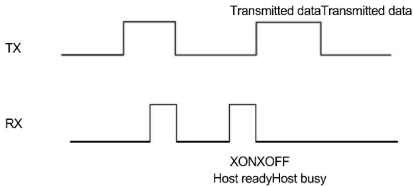
XON/XOFF handshaking
5.1.2 ACK/NACK Protocol
The transmission protocol takes place between reader, cradle and Host. The reader passes its data (code read) to the cradle which sends it to the Host.
In the following descriptions the completed transmission is indicated by the Beeper Control for Radio Response parameter with its default setting to "Good Decode and Good Reception" beep, see par. 5.7.4.
When ACK/NACK is disabled, there is no control from cradle to Host transmission, the reader responds only with the good read tone.
![graph LR A["GRYPHON™ BT"] -->|data| B["OM-GRYPHON™ BT"] B -->|data| C["Host"] B -->|cable| C](/content/2026/07/1509843/images/55d0289fc9587635061691ef44ca252d155737d29f67b0a93dc8ac08f49a7ae5.jpg)
only good read beep
ACK/NACK disabled
![graph LR A["GRYPHON™ BT"] -->|data| B["OM-GRYPHON™ BT"] B -->|data| C["Host"] B -->|NACK| C B -->|data| C B -->|ACK| C A -->|good read + good RX beep| A](/content/2026/07/1509843/images/e5862af5e736b8f209fec4fe1696cab84a56fb639ae682f66129380f4c07861c.jpg)
ACK/NACK enabled
When ACK/NACK is enabled, the Host sends an ACK character (06 HEX) in the case of good reception or the NACK character (15 HEX) requesting re-transmission, in the case of bad reception. Only after the ACK character is received by the OM-GRYPHON™ BT does the reader respond with the good reception tone.
If the reader does not receive an ACK or NACK, transmission is ended after the RX Timeout (see par. 5.1.3). See also Radio Protocol Timeout, par. 5.7.1.
5.1.3 RX Timeout
For OM-Gryphon™ BT, when the USB COM or RS232 interfaces are selected, or for C-Gryphon™, (fixed RS232 interface), the Host can be used to configure the devices by sending command strings (see appendix A).
This parameter can be used to automatically end data reception from the Host after the specified period of time.
If no character is received from the Host, after the timeout expires, any incomplete string (any string not terminated by
5.2 PEN PARAMETERS
5.2.1 Minimum Output Pulse
This parameter sets the duration of the output pulse corresponding to the narrowest element in the barcode. In this way the code resolution is controlled by the signal sent to the decoder, independently of the physical resolution of the code read.
The shortest pulse (200 µ s) corresponds to high-resolution code emulation and therefore a shorter transfer speed to the decoder (for decoders able to work on high-resolution codes). Likewise, longer pulses correspond to low-resolution code emulation and therefore a longer transfer time to the decoder.
5.2.2 Conversion to Code 39
For the Pen Emulation interface it is possible to convert all codes to Code 39. By disabling this option the decoded codes will be transmitted in their original format; except for the following codes which are ALWAYS converted into Code 39 format: MSI, Plessey, Telepen, Delta IBM, Code 11, Code 16K, Code 49 and RSS Codes.
5.2.3 Overflow
This parameter generates a white space before the first bar and after the last bar of the code. The selections are as follows:
narrow = space 10 times the minimum output pulse.
medium = space 20 times the minimum output pulse.
wide = space 30 times the minimum output pulse.
5.2.4 Output and Idle Levels
The following state diagrams describe the different output and idle level combinations for Pen Emulation:

Output and Idle Levels
5.2.5 Inter-Block Delay
For the Pen Emulation interface, data are sent to the Host in fixed size blocks of 20 characters each. The inter-block delay parameter allows setting a delay between each block sent to the Host.
5.3 DATA FORMAT
The output message from Gryphon™ BT towards the Host uses the following format:
[Bluetooth® Reader Addr] [Reader Addr Delimiter] [Header] [Code ID] [Code Length] CODE [Terminator]
[Items in square brackets are optional.]
5.3.1 Header/Terminator Selection
The header/terminator selection is not effected by the reading of the restore default code. In fact, header and terminator default values depend on the interface selection:
RS232 and USB-COM: no header, terminator CR-LF
WEDGE and USB-KBD: no header, terminator ENTER
WEDGE ALT-MODE and USB-KBD-ALT-MODE: no header, terminator CR
These default values are always restored through the reading of the relative interface selection code, see sub-paragraphs under 3.2.
For the USB KBD and WEDGE interfaces, the extended keyboard values in appendix C can also be configured.
For the Wedge Interfaces indicated in the table below, only the extended keyboard values shown in the table can be configured:
| EXTENDED KEYBOARD TO HEX CONVERSION TABLE | |||
| IBM XT IBM 31xx, 32xx, 34xx, 37xx Wyse, Digital | |||
| HEX | KEY | KEY | KEY |
| 83 ENTER | FIELD | EXIT | RETURN |
| 84 TAB | TAB | TAB | |
| 85 F1 | F1 | F1 | |
| 86 F2 | F2 | F2 | |
| 87 F3 | F3 | F3 | |
| 88 F4 | F4 | F4 | |
| 89 F5 | F5 | F5 | |
| 8A | F6 | F6 | F6 |
| 8B | F7 | F7 | F7 |
| 8C | F8 | F8 | F8 |
| 8D | F9 | F9 | F9 |
| 8E | F10 | F10 | F10 |
| 8F | ESC | F11 | F11 |
| 90 | BACKSPACE | F12 | F12 |
| 91 | HOME | ENTER | F13 |
| 92 | END | RESET | F14 |
| 93 | PG UP | INSERT | F15 |
| 94 | PG DOWN | DELETE | F16 |
| 95 | ↑ | FIELD - | UP |
| 96 | ↓ | FIELD + | DOWN |
| 97 | ← | ENTER (Paddle) | LEFT |
| 98 | → | RIGHT | |
| 99 | ESC | ESC | |
| 9A | CTRL (Right) | CTRL (Right) | |
For these Wedge interfaces, all values from 9B to FE send the Space character.
5.3.2 Address Stamping
It is possible to include the reader's Bluetooth® address in the message sent to the host. This address is a 12-character hexadecimal string that is unique to every Bluetooth® device. For message output format, refer to par. 5.3.
5.3.3 Address Delimiter
The Address Delimiter allows a character to be included to separate the reader's Bluetooth® address stamping field from the next field in the message. Any character can be included in the hexadecimal range from 00 to FE. For message output format, refer to par. 5.3.
5.4 READING PARAMETERS
5.4.1 Hand-Held and Stand Operation
Hand-Held Operation refers to using the reader by positioning it in your hand, aiming it at codes to be read and usually pressing the trigger to read them.
Stand Operation allows the reader to be positioned in the stand where it can automatically read codes placed under its reading zone.
These parameter groups allow setting different reading modes for Hand-Held Operation and Stand Operation:
- SoftwareTrigger: the reader is set in FLASH MODE. Code reading takes place during the flash on time;
- Hardware Trigger: the code reading is started with a trigger press (ON);
- Hardware Trigger Ready: the illuminator is switched ON when the reader sees a code. It functions as a pointer aiming at the code to be read. The reading phase starts only when the trigger is pressed. In this mode the reader is automatically set to trigger active level and one read per cycle parameters. (Only for Hand-Held Operation).
- Automatic: the illuminator is switched ON when the reader sees a code. The reading phase starts automatically.
Selections other than Hardware Trigger constantly consume battery power.
5.4.2 Hardware Trigger Signal
This parameter determines how the reader ON state is controlled for readers with button/trigger when Hardware Trigger is selected:
- Trigger Level: the reader goes ON when the trigger is pressed and goes OFF when it is released
- Trigger Pulse: the reader goes ON at the first trigger press and goes OFF only at a second press
5.4.3 Trigger-Off Timeout
When this timeout is selected, the reader turns OFF automatically after the desired period of time.
5.4.4 Reads per Cycle
In general, a reading cycle corresponds to the ON + OFF times of a device. The resulting effects of this parameter on code reading depend on other related configuration conditions. Here are the definitions of ON and OFF times.
- For readers using the software trigger parameter (FLASH MODE), a reading cycle corresponds to the flash on + flash off times. Code reading takes place during the flash on time.
- For readers using the hardware trigger parameter, a reading cycle corresponds to a trigger press (ON) + one of the following OFF events:
trigger release (for trigger active level)
a second trigger press (for trigger active pulse)
trigger-off timeout (see par. 5.4.3).
When one read per cycle is selected, the device decodes only one code during the ON period and immediately turns the reader OFF. It is only possible to read another code when the next ON time occurs.
In multiple reads per cycle, the ON period is extended so that the device can continue decoding codes until an OFF event occurs. For software trigger mode, the flash on period is immediately reset after each read and therefore extended. If another code is decoded before the reset flash on period expires, it is again reset and the effect is that the device remains ON, decoding codes until the flash on or timeout period expires.
The Safety Time parameter should be used in this case to avoid unwanted multiple reading of the same code, see par. 5.4.5.
5.4.5 Safety Time
Safety time prevents the device from immediately decoding the same code more than once. Same code consecutive reading can be disabled requiring the reader to be removed from the code (no decoding) for at least 400 ms, or a timeout can be set up to 9.9 seconds before the decoder will accept the same code. Reading is immediate if the code changes.
For Automatic Hand-Held or Stand Operation, the Safety Time parameter is forced to no code consecutive reading (00).
The safety time parameter is not applicable when reading stacked codes or when setting one read per cycle in hardware trigger operating mode, since these settings require voluntary action by the user.
5.5 DECODING PARAMETERS

These parameters are intended to enhance the decoding capability of the reader for particular applications. Used incorrectly, they can degrade the reading performance or increase the possibility of a decoding error.
5.5.1 Ink-Spread
The ink-spread parameter allows the decoding of codes which are not perfectly printed because the page texture tends to absorb the ink.
5.5.2 Overflow Control
The overflow control parameter can be disabled when decoding codes printed on small surfaces, which don't allow the use of an overflow space.
This command does not effect code families 2/5, Code 128 and Code 93.
5.5.3 Interdigit Control
The interdigit control parameter verifies the interdigit spacing for code families Code 39 and Codabar.
5.6 ADVANCED FORMATTING
5.6.1 Zebra Printer Formatting
Some Zebra Bluetooth ® Printers (example: Cameo 3 BT or similar type) allow format files (pre-loaded in its memory) to be selected for printing labels with different formatting. These files can be preloaded onto the Zebra printer using the "Label Vista ™ " program.
Gryphon™ BT as Master provides the possibility to define a number of formatting parameters and their relative values (type), which can be passed to the printer format files globally, (one setting is valid for all 16 possible pre-defined printer format files). You can set between 0 and 4 parameters, which can be of two types, barcode data or code ID.
Setting 0 parameters means printing a label with no barcode or code ID information. Setting between 1 and 4 parameters allows printing barcode labels with barcode and/or code ID information. The number of barcode/code ID values selected must match the number of printer parameters selected.
The Gryphon™ BT default setting is:
“! UF DLFMT00.FMT[CR][LF]barcoderead[CR][LF]barcoderead[CR][LF]”
where Gryphon™ BT sends two parameters (both barcode data) to file 00. The assumption is that one barcode is used to print the actual barcode and the other is used to print the human readable numbers of the barcode all on the same label.
Not all barcode symbologies read by Gryphon™ BT are managed by the printer, see your printer documentation for a list of printable barcode symbologies.
Note: "barcoderead" can also be a barcode formatted with headers and terminators.
5.6.2 Zebra Printer Format File Selection
Select the number of the Zebra printer format file which is pre-loaded in the printer memory and contains the graphic and parameter value information for printing a label. These files must be programmed correctly to accept the data passed to them from the Gryphon™ BT reader.
5.7 COMMON RADIO PARAMETERS
5.7.1 Radio Protocol Timeout
This parameter sets the valid time to wait before transmission between the Gryphon™ BT reader and the OM-Gryphon™ BT or remote Bluetooth® device is considered failed.
This parameter should be set taking into consideration the radio traffic or cradle transmission speed. It can be set between 3 and 19 seconds.
5.7.2 Transmission Retry
This parameter allows setting a period of time in which transmission of the previously read barcode will automatically be retried. If not disabled (00), this value must be at least equal to double the Radio Protocol Timeout value (see par. 5.7.1).
Each time transmission is retried, the reader emits a beep tone lower than the "Good Decode" beep tone.
Transmission retry is always valid for communication with OM-Gryphon™ BT. It is valid for communication with BT devices only if ACK/NACK Protocol is enabled (see par. 5.8.1).
5.7.3 Power-Off Timeout
If this command is enabled, after the desired timeout in hours, the Gryphon™ BT batteries are disconnected and all power consumption ceases. To restore power, press the trigger once. The reader will now be ready to read codes.
Power-off does not effect configuration parameters.
5.7.4 Beeper Control for Radio Response
The data entry good read tone normally results in two beeps; the first indicates that the reader has decoded the code, the second indicates whether the remote Bluetooth ® device has received the data.
This can be changed according to the following selections:
Good Decode and Good Reception: both good decode and good reception are signaled (two beeps).
♦ Only Good Decode: only the first beep indicating a good read is signaled.
- Only Good Reception: only the second beep indicating a good reception is signaled.
Off: Neither good read nor good reception beeps are signaled.
For all configurations, any transmission errors will always be signaled.
5.8 RADIO PARAMETERS FOR BT DEVICE CONFIGURATIONS
5.8.1 ACK/NACK Protocol and Frame Packing
ACK/NACK Protocol
The transmission protocol takes place between the reader and the Host. The reader passes its data (code read) to the remote Bluetooth ® device (Host).
In the following descriptions the completed transmission is indicated by the Beeper Control for Radio Response parameter with its default setting to "Good Decode and Good Reception" beep, see par. 5.7.4.
When ACK/NACK is disabled, there is no control from reader to Host transmission, therefore the reader responds only with the good read tone.
![graph LR A["GRYPHON™ BT"] -->|data| B["Host with Bluetooth® device"] B -->|only good read beep| A](/content/2026/07/1509843/images/e7ead03143ed5fa586f0d5432041615e875b713ce563fcdab0515cafbf08b300.jpg)
ACK/NACK disabled
![graph LR A["GRYPHON™ BT"] -->|good read + good RX beep| B["data"] B --> C["NACK"] C --> D["Host with Bluetooth® device"] D -->|data| B B -->|data| C C -->|ACK| D](/content/2026/07/1509843/images/88a6065a21ede5ee35ca51dba61062ef75d1099f79853fc052330321db674f24.jpg)
ACK/NACK enabled
When ACK/NACK is enabled, the Host sends an ACK character (06 HEX) in the case of good reception or the NACK character (15 HEX) requesting re-transmission, in the case of bad reception. Only after the ACK character is received by Gryphon™ BT does the reader respond with the good reception tone.
If the reader does not receive an ACK or NACK, transmission is ended after the Radio Protocol Timeout, par. 5.7.1, or retried if transmission retry is enabled, par. 5.7.2.
Frame Packing
When Frame Packing is disabled, the Output Message from the Gryphon™ BT reader is sent to the Host as is, see par. 5.3.
If instead, Frame Packing is enabled, the Output Message is "packed" into a Frame with the following format:
STX Length Control Counter Output Message CRC-16 CR
where:
STX = Frame Start character (02 Hex).
Length = 2 bytes; indicates frame length of the remaining fields (including CR).
Control = 1 byte; indicates message fragmentation. For further details see the DL Security Protocol documentation on the CD-ROM.
Counter = a loop counter for the Output Message characters (bytes) that cycles from 0 to 255 and then restarts.
Output Message = complete text message from the Gryphon™ BT reader including optional fields as shown in par. 5.3. The maximum length of this field is 304 bytes.
CRC-16) = 2 bytes; 16-bit Cyclic Redundancy Check based on the hex 1021 polynomial and performed on all bytes from Length up to the CRC itself. The MSB is sent first. For further details see the DL Security Protocol documentation on the CD-ROM.
CR = Frame Stop character (0D Hex).
To simplify the management of this frame packing, and to avoid having to develop a special proprietary software program, included on the CD-ROM are: the DL Security Protocol example program, (written in Visual Basic), the WindIbt.dll, and the source code of the example. The example program allows extraction of the data from the frame, verification of the CRC, discarding any duplicate data (with the same counter value), and automatic management of Frame Packing and ACK/NACK protocol in response to each frame.
5.8.2 User Friendly Name
This parameter provides a way to identify the Gryphon™ BT reader in a human readable (user-friendly), format. This name is returned with the reader configuration parameters (see par. 6.2). The name is made up of a fixed 20-character field. If you choose to use a name that is less than 20 characters, you must fill in the blanks with a valid character (i.e. space character). Valid characters are in the range 00 - 7E and must be entered in hex format.
5.8.3 Auto-Connection (Master only)
Upon power-up, the Gryphon TM BT reader makes attempts to connect with the remote Bluetooth device (Slave). If the connection is not successful, the reader remains on, but not connected.
In this case reconnection can be requested by double clicking the reader trigger or by reading the "Request Radio Connection" command in par. 6.1.
5.8.4 Auto-Reconnection (Master only)
If a radio connection is interrupted, the Gryphon TM BT reader makes attempts to reconnect with the remote Bluetooth device (Slave). If the connection is not successful, the reader remains on, but not connected.
In this case reconnection can be requested by double clicking the reader trigger or by reading the "Request Radio Connection" command in par. 6.1.
5.9 RADIO PARAMETERS FOR OM-GRYPHON™ BT CONFIGURATIONS
5.9.1 Batch Mode
Batch mode allows codes to be stored in the gun on a FIFO basis whenever the gun is out of range. If transmission cannot be successfully completed, then the code is added to the list. When the gun returns in range, transmission of the codes to the cradle resumes automatically by successfully reading a new code.
5.10 DEFAULT PARAMETERS FOR POS TERMINALS
The default values of the RS232 and Data Format parameters for POS terminals are listed in the following table:
| NIXDORF Mode A FUJITSU ICL Mode | |||
| RS232 Group | |||
| Baud Rate 9600 9600 9600 | |||
| Parity | Odd | None | |
| Data Bits 8 8 8 | |||
| Stop Bits | 1 1 1 | ||
| Handshaking | Hardware (RTS/CTS) | None | RTS always ON |
| ACK/NACK Protocol | Disabled | Disabled | Disabled |
| FIFO | Enabled | Enabled | Enabled |
| Inter-Character Delay | Disabled | Disabled | Disabled |
| RX Timeout | 9.9 sec | 2 sec | 9.9 sec |
| Serial Trigger Lock | Disabled | Disabled | Disabled |
| Data Format Group | |||
| Code Identifier | Custom | Custom | Custom |
| Header | No Header | No Header | No Header |
| Terminator | CR | CR | CR |
| Field Adjustment | Disabled | Disabled | Disabled |
| Code Length TX | Not Transmitted | Not Transmitted | Not Transmitted |
| Character Replacement | Disabled | Disabled | Disabled |
| Address Stamping | Disabled | Disabled | Disabled |
| Address Delimiter | Disabled | Disabled | Disabled |
The table below lists all the Code Identifiers available for the POS terminals:
| CODE | NIXDORF Mode A FUJITSU ICL Mode | ||
| UPC-A | A0 | A | A |
| UPC-E | C | E | E |
| EAN-8 | B | FF | FF |
| EAN-13 | A | F | F |
| Code 39 | M | None | C [code length] |
| Codabar | N | None | N [code length] |
| Code 128 | K | None | L [code length] |
| Interleaved 2 of 5 | I | None I [code length] | |
| Code 93 | L | None | None |
| Industrial 2 of 5 | H | None | H [code length] |
| Normal 2 of 5 | H | None | H [code length] |
| UCC/EAN 128 P | None | L [code length] | |
| MSI/Plessey | O | None | None |
| RSS | E | None | None |
| PDF417 | Q | None | None |
| Other | None | None | None |
6 SYSTEM MANAGEMENT COMMANDS
6.1 RADIO MANAGEMENT COMMANDS
The following commands carry out their specific function and then exit the configuration environment.
| Command | Description |
 | Unbind the reader preventing the connection to a cradle to which it was previously bound. |
 | Power the reader off. At power-on, auto-connection is attempted only if enabled. |
 | Request Radio Disconnection (Master only) |
 | Request Radio Connection (Master only)This request can also be performed by double clicking the reader trigger. |
6.2 GRYPHON™ BT MANAGEMENT COMMANDS
The following commands carry out their specific function and then exit the configuration environment.
 | Restore the GryphonTM BT reader default configuration.This command does not reset:role (Master /Slave)remote Bluetoothaddressuser-friendly nameheader/terminator |
 | Transmit the GryphonTM BT Software release to Host via radio. |
 | Transmit GryphonTM BT reader configuration in ASCII format to Host via radio. |
 | Transmit GryphonTM BT reader configuration in ASCII format to Host via cradle (OM-GryphonTM BT or C-Gryphon). GryphonTM BT reader must be placed onto the cradle. |
 | Transmit GryphonTM BT address (BT_ADDR) to Host via cradle (OM-GryphonTM BT or C-Gryphon). GryphonTM BT reader must be placed onto the cradle. |
6.3 OM-GRYPHON™ BT MANAGEMENT COMMANDS
The following commands carry out their specific function and then exit the configuration environment.

Restore the OM-Gryphon™ BT cradle default configuration.
This command does not reset:
- remote Bluetooth gun address
- header/terminator
- keyboard character assignment

Transmit the OM-Gryphon™ BT Software release to Host.

Transmit OM-Gryphon™ BT configuration in ASCII format to Host.
6.4 CRADLE CHARGING MANAGEMENT
Battery selection is required only when the Gryphon™ BT reader has an Alkaline battery and you want to use the OM-Gryphon™ BT or C-Gryphon either for serial configuration, software upgrades or to hold Gryphon™ BT. Since this type of battery must not be charged it is necessary to disable the cradle charge function by following the procedure:
- With the Gryphon™ BT read the following code:

The blue LED on the Gryphon™ BT will blink, signaling the reader has accepted the command.
- Place the reader onto the charger within 4 seconds. The blue LED turns off and a short beep is emitted
To enable the charge function repeat step 1 and 2 substituting the "Alkaline" code with the following one:


Attempts to charge Alkaline batteries could cause leakage of liquid, generation of heat or, in extreme cases, explosion. If using Alkaline batteries, carefully follow the procedure above to avoid damage.
7 TROUBLESHOOTING
| Problem | Solution |
| The beeper and LED signal radio disconnection from the remote Bluetooth® device. | The distance between the remote device and GryphonTM BT may be too far or there may be obstacles to radio transmission between them.Reconnect. |
| The requested radio connection by GryphonTM BT Master does not activate. | Reduce the distance between the devices.Check that GryphonTM BT is powered (batteries are charged), that the radio protocol software version is compatible with GryphonTM BT, that there is not already another BT device connected using the same SPP profile.Insert the remote device address again to GryphonTM BT.Check the GryphonTM BT configuration using the Transmit configuration command via C-Gryphon cradle. |
| The remote Bluetooth® device recognizes GryphonTM BT but cannot connect to it. | Check that there are no limits set to the connection such as a password.Check that the radio protocol software version is compatible with GryphonTM BT. |
| The radio range seems reduced. | Check that there are no obstacles to radio transmission between the devices. |
| A GryphonTM BT Master fails to make an automatic connection. | Double-click the trigger to force an immediate retry of the radio connection or read the "Request Radio Connection" code in par. 6.1. |
| A GryphonTM BT Master remains connected to a Slave device. | Read the "Request Radio Disconnection" code in par. 6.1 or power off the Bluetooth® Slave device. |
| A GryphonTM BT gun continuously connects and disconnects from its OM-GryphonTM BT cradle | A second gun has erroneously remained connected to the cradle. Unbind the second gun using the command in par. 6.1.The OM-GryphonTM BT has lost the Bind address, for example after a software upgrade, and therefore refuses any connection. Repeat the Bind procedure. |
8 TECHNICAL FEATURES
8.1 GRYPHON™ BT
| Electrical Features | |
| Battery Type 2 AA NiMh batteries* | 1.2 V – 1850 mAh or 2100 mAh |
| Time of recharge max. 5 hours | |
| Operating autonomy(typ. continuous reading) | >14 hours |
| Max scan rate 270 scans/sec | |
| Indicators LED, Good Read Spot, Beeper | |
| Optical Features | |
| Sensor CCD solid state (3648 pixels) | |
| IlluminatorWavelength 630 ~ 670 nmMax. LED Output Power 0.33 mWLED Safety Class Class 1 EN60825-1Reading field see reading diagram (par. 8.5) | |
| Max. resolution 0.076 mm, 3 mils | |
| PCS minimum 15% (Datalogic Test Chart) | |
| Reading Pitch angle 65° | |
| Reading Skew angle | 80° |
| Reading Tilt angle | 35° |
| Radio Features | |
| Bluetooth®version | Bluetooth®1.2 |
| Profiles supported | Serial Port Profile |
| Class | IEEE 802.15 class 2 |
| Environmental Features | |
| Working Temperature | 0° to + 40 °C / 32° to 104 °F |
| Storage Temperature(without battery) | -20°to + 70 °C / - 4° to 158 °F |
| Humidity | 90% non condensing |
| Drop resistance | IEC 68-2-32 Test Ed; 1.8 m on concrete |
| Ambient light immunity | 100000 lux (sunlight) / 4000 lux (artificial light) |
| Protection class | IP30 |
* It is possible to employ also NiCd or non-chargeable Alkaline AA batteries.
| Mechanical Features | |
| Weight (with batteries) about 2 | 80 g. / 9.87 oz |
| Dimensions 179 x 81 x 98 mm | / 7.04 x 3.18 x 3.85 in |
| Material ABS and Polycarbonate molded with rubber | |
| Decoding Capability | |
| Readable codes EAN/UPC, IS | BN/ISSN, 2/5 family (IATA), Code 39(plus Code 32, Cip 39), Codabar, Code 93, MSI,Plessey, Telepen, Delta IBM, Code 11, EAN 128,Code 128, ISBT 128, Code 16K, Code 49, RSSfamily, PDF417 (PDF models only) |
| Other features Encryption, Batch mode | |
8.2 OM-GRYPHON™ BT
| Electrical Features | |
| Supply voltage 9..28 Vdc | |
| Power consumption max. 8 W | (charging) * |
| Indicators | Battery charging (red)Charge completed (green)Power/Data (yellow) |
| Time of recharge max. 5 hours | |
| Environmental Features | |
| Working temperature 0° to +40 °C / 32° to 104 °F | |
| Storage temperature -20° to +70 °C / -4° to 158 °F | |
| Humidity 90 % non condensing | |
| Protection class IP30 | |
| Communications | |
| Interface USB, RS232, Wedge, Pen emulation | |
| Mechanical Features | |
| Weight about 250 g. / 8.81 oz | |
| Dimensions | 208 x 107 x 55.5 mm / 8.1 x 4.2 x 2.18 in |
| Material | ABS |
* Having a switching regulator inside, the OM-Gryphon™ draws the same power, regardless of the supply voltage, i.e. as the input voltage increases the current drawn decreases.
8.3 C-GRYPHON™
| Electrical Features | |
| Supply voltage 9..28 Vdc | |
| Power consumption max. 8 W | (charging) * |
| Indicators | Battery charging (red)Charge completed (green)Power (yellow) |
| Time of recharge max. 5 hours | |
| Environmental Features | |
| Working temperature 0° to +40 °C / 32° to 104 °F | |
| Storage temperature -20° to +70 °C / -4° to 158 °F | |
| Humidity 90 % non condensing | |
| Protection class IP30 | |
| Communications | |
| Interface | RS232 |
| Baud Rate 9600 | |
| Data Bits 8 | |
| Stop Bit 1 | |
| Parity | None |
| Mechanical Features | |
| Weight about 250 g. / 8.81 oz | |
| Dimensions 208 x 107 x 55.5 mm / 8.1 x 4.2 x 2.18 in | |
| Material | ABS |
* Having a switching regulator inside, the OM-Gryphon™ draws the same power, regardless of the supply voltage, i.e. as the input voltage increases the current drawn decreases.
8.4 STATUS INDICATORS
The reader has three indicators, LED, Beeper and Good Read Spot. They signal several operating conditions which are described in the tables below.
H = high tone
M = medium tone
L = low tone
GRYPHON™ BT READER START-UP
| Beeper1 | Meaning |
| LLLL H Parameters loaded correctly, radio OK | |
| LLLL HLHL Parameters loaded correctly, no answer from radio | |
| HH HH long tones | Parameter loading error, reading or writing error in the non volatile memory |
| HLHL Hardware error in EEPROM | |
GRYPHON™ BT READER CONFIGURATION
| Beeper 1 | Meaning |
| H H H H Correct entry or exit from Configuration mode | |
| L Good read of a command | |
| L L L Command read error | |
GRYPHON™ BT POWER
| Beeper LED | Meaning | |
| 10 short H 10 | short blinks Low Battery |
1 Only the Beeper Intensity command can modify these signals.
GRYPHON™ BT READER DATA ENTRY
| Beeper 1 | LED | Good Read Spot Meaning | |
| one beep 2 ON | ON | Correct read of a code in normal mode | |
| muffled and long sound | Batch mode entered upon | transmission failure | |
| H L long | TX | error between Gryphon TM BT and remoteBluetooth ® device | |
| H H H T | meout | expired – operation not completed | |
| OFF | OFF Ready to read a code | ||
GRYPHON™ BT READER STATUS
| Beeper 1 | LED | Meaning |
| L M M H | Radio connection | |
| H M M L | Radio disconnection | |
| 1 blink / 2 sec. | Radio connected | |
| 2 blinks / 2 sec. | Radio not connected | |
| ticks | Short blinks (Master only) | Connection / re-connection attempts |
1 Only the Beeper Intensity command can modify these signals.
2 The data entry good read tone is user-configurable with all the Beeper commands in the Reading Parameters section.
Normally this results in two beeps; the first indicates that the reader has decoded the code, the second indicates whether the remote Bluetooth ® device has received the data.
The OM-Gryphon™ BT and C-Gryphon cradles have three LEDs. They signal several operating conditions which are described in the tables below.
OM-GRYPHON™ BT / C-GRYPHON CHARGE STATUS
| Red LED Green LED Meaning | ||
| ON | OFF | Charging |
| OFF ON | End of charge | |
| OFF OFF | No gun inserted | |
| Flashing | Flashing Reader not | correctly placed onto the charger;shorted or open battery |
OM-GRYPHON™ BT / C-GRYPHON POWER/COMMUNICATION
| Yellow LED Meaning | |
| ON | Power applied |
| OFF Error in reading EEPROM parameters / Insufficient Voltage | |
| Blinking receives commands from the Host | |
8.5 READING DIAGRAMS
GRYPHON™ BT100

GRYPHON™ BT200

PDF417 codes, Reading Zones (10° skew angle)

A HOST CONFIGURATION STRINGS
In this section we provide a description of how to modify the Gryphon™ BT and OM-Gryphon™ BT configuration using serial strings sent from the Host.
The configuration must be performed in different ways according to the device to be configured:
- OM-Gryphon™ BT
the configuration strings are sent from the Host directly to the device through the RS232/USB COM interface;
• Gryphon™ BT connected with OM-Gryphon™ BT or C-Gryphon
the configuration of the reader when placed onto a cradle is sent from the Host through the RS232/USB COM interface (RS232 only for C-Gryphon).
When this method is used, the programming sequence format is the following:
![graph TD A["Command"] --> B["Character sequence in following tables"] B --> C["Enter configuration environment"] D["CR-+"] --> E["Carriage return character (0D Hex.)"] E --> F["Exit and Save configuration"]](/content/2026/07/1509843/images/f3efa0e8c6f02daa2e48b9bf70e75309bef659c84adc1721ff476ccadf23d3dd.jpg)
Example:
Multiple command programming sequence:
![graph TD A["$+"] --> B["BG1"] B --> C["AC410132BH0$-"] C --> D["CR"] D --> E["Carriage return character (0D Hex.)"] D --> F["Exit and save new configuration"] D --> G["Matrix 2/5 3 bars: no check digit, variable length code from 1 to 32 characters"] G --> H["Beeper tone 1"] G --> I["Beeper low inten…](/content/2026/07/1509843/images/a5fda8f90d5337f2352f353f1f2bd97685c60a831b51b08997f115ac53958b3a.jpg)
Each configuration parameter setting removes the condition previously active for that parameter.

NOTE
The device buffer can contain about 400 characters. If your programming string goes over this value, you must split it into separate groups and send each group after a delay of at least 3 seconds to give the reader time to empty the buffer and interpret the commands.
SERIAL CONFIGURATION STRINGS
| ENTER/EXIT CONFIGURATION COMMANDS | |
| DESCRIPTION | STRING |
| Enter Configuration + | |
| Exit and Save Configuration- | |
| Restore GryphonTM BT Default +RX0- | |
| Transmit GryphonTM BT Software Release +RX1- | |
| Transmit GryphonTM BT Configuration in ASCII1 +RX2- | |
| Transmit GryphonTM BT address +QX1- | |
| Restore OM-GryphonTM BT Default +* | |
| Transmit OM-GryphonTM BT Software Release +! | |
| Transmit OM-GryphonTM BT Configuration in ASCII1 +& | |
1 For Gryphon TM BT200, this command transmits only the Bluetooth ® radio configuration.
| INTERFACE SELECTION | |||
| DESCRIPTION | STRING | ||
| USB | USB-KBD UA03 | ||
| USB-KBD-ALT-MODE UA04 | |||
| USB-KBD-APPLE UA05 | |||
| USB-COM | UA02 | ||
| USB-IBM-Table Top | UA00 | ||
| USB-IBM-Hand Held | UA01 | ||
| RS232 | Standard | CP0 | |
| ICL Mode CM0 | |||
| Fujitsu | CM1 | ||
| Nixdorf Mode A | CM2EC0 | ||
| WEDGE | for IBM AT | CP500 | |
| for IBM Terminals: 31xx, 32xx, 34xx, 37xx; make-break keyboard | CP501 | ||
| for IBM Terminals: 31xx, 32xx, 34xx, 37xx; make-only keyboard | CP502 | ||
| Keyboard Type for IBM Terminals 31xx, 32xx, 34xx, 37xx | typewriter | FK0 | |
| advanced | FK1 | ||
| for IBM XT | CP503 | ||
| for IBM Terminal 3153 | CP504 | ||
| for IBM PC Notebook | CP505 | ||
| for IBM SURE1 | CP506 | ||
| for IBM AT - ALT mode | CP507 | ||
| for IBM PC Notebook - ALT mode | CP508 | ||
| for Wyse Terminal - ANSI Keyboard | CP509 | ||
| for Wyse Terminal - PC Keyboard | CP510 | ||
| for Wyse Terminal - ASCII Keyboard | CP511 | ||
| for Wyse Terminal - VT220 style Keyboard | CP514 | ||
| for Digital Terminals VT2xx/3xx/4xx | CP512 | ||
| for Apple ADB Bus | CP513 | ||
| PEN EMULATION | CP6 | ||
| USB | ||
| DESCRIPTION | STRING | |
| USB-COM | ||
| Handshaking | disable | CE0 |
| RTS/CTS | ||
| XON/XOFF | ||
| RTS always | ||
| ACK/NACK Protocol disable ER0 | ||
| Inter-character delay (ms) CK00 - CK99 | ||
| RX Timeout (100 ms) | CL00 - CL99 | |
| Serial Trigger Lock disable CR0 | ||
| USB-KBD | ||
| Keyboard nationality Belgian (not for USB-KBD-ALT-MODE) | FJ7 | |
| English FJ4 | ||
| French | ||
| German | FJ3 | |
| Italian | FJ1 | |
| Spanish | FJ6 | |
| Swedish | ||
| USA | FJ0 | |
| Japanese | FJ8 | |
| Delays | Inter-Character (ms) | CK00 - CK99 |
| Inter-Code (s) | FG00 - FG99 | |
a= Hex value of the ASCII character from 00 to FE enabling the device trigger;
b = Hex value of the ASCII character from 00 to FE disabling the device trigger;
| RS232 | ||
| DESCRIPTION | STRING | |
| Baud rate 300 CD1 | ||
| 600 | CD2 | |
| 1200 | CD3 | |
| 2400 | CD4 | |
| 4800 | CD5 | |
| 9600 | CD6 | |
| 19200 | CD7 | |
| 38400 CD8 | ||
| Parity | none CC0 | |
| even | CC1 | |
| odd | CC2 | |
| Data bits 7 CA0 | ||
| 8 | CA1 | |
| 9 | CA2 | |
| Stop bits 1 CB0 | ||
| 2 | CB1 | |
| Handshaking | disable CE0 | |
| RTS/CTS | CE1 | |
| XON/XOFF | CE2 | |
| RTS always ON | CE3 | |
| ACK/NACK Protocol | disable | ER0 |
| enable | ER1 | |
| Inter-character delay (ms) | CK00 - CK99 | |
| RX Timeout (100 ms) | CL00 - CL99 | |
| Serial Trigger Lock | disable | CR0 |
| enable | CR1 ab | |
a= Hex value of the ASCII character from 00 to FE enabling the device trigger;
b = Hex value of the ASCII character from 00 to FE disabling the device trigger;
| WEDGE | ||
| DESCRIPTION | STRING | |
| Keyboard nationality Belgian FJ7Japanese (IBM AT compatible only) | ||
| English | FJ4 | |
| French | ||
| German | FJ3 | |
| Italian | ||
| Spanish | FJ6 | |
| Swedish | FJ5 | |
| USA | ||
| FJ8 | ||
| Caps Lock caps Lock ON FE1caps Lock OFF FE0 | ||
| Caps Lock Auto-Recognition disable(IBM AT compatible only) enable | FP0 | |
| FP1 | ||
| Num Lock | Toggle Num Lock FL1 | |
| Num Lock Unchanged | FL0 | |
| Delays | Inter-Character (ms) | CK00 - CK99 |
| Inter-Code (s) | FG00 - FG99 | |
| PEN | ||
| DESCRIPTION | STRING | |
| Operating mode | interpret (does not require + or-) | ] |
| transparent (does not require+ or -) | [ | |
| Minimum output pulse | 200μs | DG0 |
| 400μs | DG1 | |
| 600μs | DG2 | |
| 800μs | DG3 | |
| 1 ms | DG4 | |
| 1.2 ms | DG5 | |
| Conversion to Code 39 | disable conversion to Code 39 | DA0 |
| enable conversion to Code 39 | DA1 | |
| Output level | normal | DD0 |
| inverted | DD1 | |
| Idle level | normal | DE0 |
| inverted | DE1 | |
| Overflow | narrow overflow | DH0 |
| medium overflow | DH1 | |
| wide overflow | DH2 | |
| Inter-Block Delay (100 ms) | CK00-CK99 | |
| DATA FORMAT | ||
| DESCRIPTION | STRING | |
| Code Identifier disable EBO | ||
| Datalogic standard | ||
| AIM standard | ||
| Custom | ||
| Custom Code Identifier EH | abc | |
| Headers | no header | |
| one character | x | |
| two characters | xx | |
| three characters | xxx | |
| four characters | xxxx | |
| five characters | xxxxx | |
| six characters | xxxxxx | |
| seven characters | xxxxxxxx | |
| eight characters | xxxxxxxx | |
| Terminators | No terminator | EA10 |
| one character | x | |
| two characters | xx | |
| three characters | xxx | |
| four characters | xxxx | |
| five characters | xxxxx | |
| six characters | xxxxxx | |
| seven characters | xxxxxxxx | |
| eight characters | xxxxxxxx | |
EB3
E/
a = ASCII character.
b, c, x = HEX values representing an ASCII character.
a= ASCII character of the DATALOGIC STANDARD Code Identifier from the table on p. 60.
b = Hex value of the first Custom Code Identifier character from 00 to FD;
FF = disable Code Identifier
c= Hex value of the second Custom Code Identifier character from 00 to FD;
FF = disable second character of Custom Code Identifier
x= Hex value from 00 to FE
| DATA FORMAT (continued) | ||
| DESCRIPTION | STRING | |
| Code Length Tx not transmitted in variable-digit transmission in fixed 4-digit format transmitted in fixed 4-digit format | EE0 | |
| format EE1 | ||
| format EE2 | ||
| Field Adjustment disable EF0 | ||
| right addition a0d | ||
| left addition a1d | ||
| right deletion a2d | ||
| left deletion EF a3d | ||
| Field Adjustment Character EG | e | |
| Character Replacement disable character replacement EO0 | ||
| first character replacement afg01 | ||
| second character replacement EO2 afg | ||
| third character afg | ||
| Address Stamping | disable reader address stamping | QU0 |
| enable reader address stamping | QU1 | |
| Address Delimiter | disable reader address delimiter | QV0 |
| enable reader address delimiter and select character | QV1h | |
a = ASCII character.
d= a number from the Hex/Numeric Table
e, f, g, h = HEX values representing an ASCII character
a = ASCII character of the DATALOGIC STANDARD Code Identifier from the table on p. 60.
d= a number in the range 01-32 from the Hex/Numeric Table
e = Hex value from 00 to FE
f= Hex value of the character to be replaced from 00 to FE
g= Hex value of the new character to insert from 00 to FE FF = replace with no new character (remove character
h= a HEX value in the range from 00 - FE representing the ASCII character.
| POWER SAVE | ||
| DESCRIPTION | STRING | |
| Scan Rate quarter BT0 | ||
| half | BT1 | |
| maximum | BT2 | |
| READING PARAMETERS | ||
| DESCRIPTION | STRING | |
| Hand-Held Operation software trigger | BK0 | |
| hardware | trigger | |
| automatic | BK2 | |
| hardware | trigger | |
| Stand Operation software trigger BU1 | ||
| hardware | trigger | |
| automatic | BU0 | |
| Hardware Trigger Mode trigger active level trigger active pulse | BA0 | |
| BA1 | ||
| Trigger-off Timeout (s) | BD00 - BD99 | |
| FLASH ON (100 ms) | BB001 - BB099 | |
| FLASH OFF (100 ms) | BB101 - BB199 | |
| Reads per Cycle | one read | BC0 |
| multiple | reads | |
| Safety Time (100 ms) | BE00 - BE99 | |
| Beeper Intensity | very low intensity | BG0 |
| low | intensity | |
| medium | intensity | |
| high | intensity | |
| Beeper Tone | tone 1 | BH0 |
| tone | 2 | |
| tone | 3 | |
| tone | 4 | |
| Beeper Type | monotone | BJ0 |
| bitonal | BJ1 | |
| Beeper Length long | BI0 | |
| short | BI1 | |
| PDF Decoding Recognition Intensity | low | BW0 |
| high | BW1 | |
| Good Read Spot - Duration | disabled | BV0 |
| short | BV1 | |
| medium | BV2 | |
| long | BV3 | |
| DECODING PARAMETERS | ||
| DESCRIPTION | STRING | |
| Ink-spread | disable AX0 | |
| enable | AX1 | |
| Overflow control disable | AW1 | |
| enable | AW0 | |
| Interdigit control disable | AV0 | |
| enable | AV1 | |
| Puzzle SolverTM | disable AU0 | |
| enable | AU1 | |
| Decoding Safety one read | ED0 | |
| two reads | ||
| three reads | ||
| four reads | ||
| CODE SELECTION | |||
| DESCRIPTION | STRING | ||
| DISABLE ALL FAMILY CODES | AZ0 | ||
| EAN/UPC | disable EAN/UPC family | AA0 | |
| EAN 8/EAN 13/UPC A/UPC E | without ADD ON | AA1 | |
| with ADD ON | AA5 | ||
| with and without ADD ON | AA8 | ||
| EAN 8/EAN 13 | without ADD ON | AA3 | |
| with ADD ON 2 ONLY | AAK | ||
| with ADD ON 5 ONLY AAL | |||
| with ADD ON 2 AND 5 | AA6 | ||
| UPC A/UPC E | without ADD ON | AA4 | |
| with ADD ON 2 ONLY | AAM | ||
| with ADD ON 5 ONLY | AAN | ||
| with ADD ON 2 AND 5 | AA7 | ||
| EAN 8 check digit transmission | disable | AAG0 | |
| enable | AAG1 | ||
| EAN 13 check digit transmission | disable | AAH0 | |
| enable | AAH1 | ||
| UPC A check digit transmission | disable | AAI0 | |
| enable | AAI1 | ||
| UPC E check digit transmission | disable | AAJ0 | |
| enable | AAJ1 | ||
| conversions | UPC E to UPC A | AAA | |
| UPC E to EAN 13 | AAB | ||
| UPC A to EAN 13 | AAC | ||
| EAN 8 to EAN 13 | AAD | ||
| CODE SELECTION (continued) | |||
| DESCRIPTION | STRING | ||
| ISBN Conversion codes | enable ISBN AP1 | ||
| enable ISSN AP2 | |||
| enable ISBN and ISSN AP3 | |||
| disable ISBN and ISSN AP0 | |||
| Code 39 disable Code 39 family AB0 | |||
| Standard no check digit control and transmission control without transm | check digit control AB11 | ||
| Full ASCII no check digit control and transmission control without transm | no check digit control AB21 | ||
| CIP 39 | |||
| Code 32 | |||
| code length | xxxx | ||
| 2/5 | disable Code 2/5 family | AC0 | |
| Interleaved 2/5 | no check digit control | AC11xxxx | |
| check digit control and transmission | AC12xxxx | ||
| check digit control without transmission | AC13xxxx | ||
| Normal 2/5 5 bars | no check digit control | AC21xxxx | |
| check digit control and transmission | AC22xxxx | ||
| check digit control without transmission | AC23xxxx | ||
| Industrial 2/5 (IATA) | no check digit control | AC31xxxx | |
| check digit control and transmission | AC32xxxx | ||
| check digit control without transmission | AC33xxxx | ||
| Matrix 2/5 3 bars | no check digit control | AC41xxxx | |
| check digit control and transmission | AC42xxxx | ||
| check digit control without transmission | AC43xxxx | ||
| CIP/HR | AC5 | ||
AB4 AB*
xxxx = ASCII numbers that define the code length where:
- First 2 digits = minimum acceptable code length.
• Second 2 digits = maximum acceptable code length.
The minimum code length must always be less than or equal to the maximum.
The maximum code length for all codes is 99 characters:
Examples:
0132 = variable length from 1 to 32 digits in the code.
1010 = 10 digit code length only.
| CODE SELECTION (continued) | |||
| DESCRIPTION | STRING | ||
| Codabar Standard no start/stop character equality control | disable Codabar family AD0 | ||
| no start/stop character equality control | quality control nor transmission | AD111 | |
| character equality control | but transmission | AD112 | |
| character equality control | but no transmission | AD121 | |
| character equality control | and transmission | AD122 | |
| ABC Codabar no start/stop character equality control | char stop character equality control | equality control but transmission | AD212 |
| Codabar ABC forced concatenation AD232 | |||
| start/stop char code length | AD*xxxx | ||
| character case in transmission lower case upper | ADA0 | ||
| case | |||
| Code 128 | disable Code 128 family | AI0 | |
| enable Code 128 - control without transmission of check digit | AI11 | ||
| enable EAN 128 - control without transmission of check digit | AI21 | ||
| transmit GS before Code | disable | EQ0 | |
| enable | EQ1 | ||
| ISBT 128 | enable ISBT 128 | AI31 | |
| code length | AILxxxx | ||
| Code 93 | disable Code 93 family | AK0 | |
| enable Code 93 - control without transmission of check digit | AK1 | ||
ADA1
xxxx = ASCII numbers that define the code length where:
- First 2 digits = minimum acceptable code length.
• Second 2 digits = maximum acceptable code length.
The minimum code length must always be less than or equal to the maximum.
The maximum code length for all codes is 99 characters:
EXAMPLES:
0132 = variable length from 1 to 32 digits in the code.
1010 = 10 digit code length only.
| CODE SELECTION (continued) | ||
| DESCRIPTION | STRING | |
| MSI disable the family AE0 | ||
| no check | ||
| MOD10 no tx | ||
| MOD10 with tx | ||
| MOD11-MOD10 no | ||
| MOD11-MOD10 with | ||
| MOD10-MOD10 no | ||
| MOD10-MOD10 with | ||
| Plessey disable the family AF0 | ||
| Standard no check | AF11 | |
| Standard check - with tx AF12 | ||
| Standard check - no tx AF13 | ||
| Anker no check AF21 | ||
| Anker check - with tx | AF22 | |
| Anker check - no tx | AF23 | |
| Telepen | disable the family AL0 | |
| Numeric no check | AL11 | |
| Numeric check - with tx | AL12 | |
| Numeric check - no tx | AL13 | |
| Alpha no check | AL21 | |
| Alpha check - with tx | AL22 | |
| Alpha check - no tx | AL23 | |
| Delta IBM | disable the family AH0 | |
| no check | ||
| Type 1 check | ||
| Type 2 check | ||
| Code 11 | disable the family | AG0 |
| no check | ||
| Type C with tx | AG21 | |
| Type C no tx | AG22 | |
| Type K with tx | AG31 | |
| Type K no tx | AG32 | |
| Type C and K with tx | AG41 | |
| Type C and K no tx | AG42 | |
| Code 16K | disable | AJ0 |
| enable | AJ1 | |
| Code 49 | disable | AM0 |
| enable | ||
| RSS disable the family | AQ0 | |
| disable RSS Expanded | ed Linear and Stacked AQ10 | |
| enable RSS Expanded | ed Linear and Stacked AQ11 | |
| disable RSS Limited | AQ20 | |
| enable RSS Limited | AQ21 | |
| disable RSS 14 Line | ar and Stacked AQ30 | |
| enable RSS 14 Line | ar and Stacked AQ31 | |
| PDF417 | disable AR0 | |
| enable AR1 | ||
| RADIO PARAMETERS | ||
| DESCRIPTION | STRING | |
| Radio Protocol Timeout | enable (seconds) | |
| Power-Off Timeout RP00-RP99 | ||
| User-Friendly Name change user-friendly name | QN | a |
| restore factory user-friendly name | QK | |
| Beeper Control For Radio Response | good decode + good reception | BF0 |
| only good decode | BF1 | |
| only good reception | BF2 | |
| off | BF3 | |
| Transmission Retry (s) | QO00 - QO60 | |
| ACK/NACK Protocol and Frame Packing | No ACK/NACK nor Frame Packing | QL0 |
| ACK/NACK only | QL1 | |
| Frame Packing only | QL2 | |
| ACK/NACK and Frame Packing | QL3 | |
| Auto-Connection (Master only) | disable | QA0 |
| enable | QA1 | |
| Auto-Reconnection (Master only) | disable | QM0 |
| enable | QM1 | |
| Encryption | disable | QB0 |
| enable | QB1 | |
| Batch Mode | disable | QE0 |
| enable | QE1 | |
a = 20 ASCII characters represented as Hex values in the range 00 to 7E
2/5 Interleaved 2/5 Industrial


2/5 normal 5 bars 2/5 matrix 3 bars


EAN 8 EAN 13


UPC A UPC E


EAN 8 with 2 ADD ON EAN 8 with 5 ADD ON


EAN 13 with 2 ADD ON EAN 13 with 5 ADD ON


UPC A with 2 ADD ON UPC A with 5 ADD ON


UPC E with 2 ADD ON UPC E with 5 ADD ON

Code 39 Code 39 Full ASCII

CODABAR

ABC
COD
Code 128 EAN 128

ISBT 128 CIP/HR

CIP/39

Code
Code 93 MSI

Plessey Standard Plessey Anker


Delta IBM Telepen


Code 16K Code 11


Code 49 RSS Expanded Linear and Stacked


RSS Limited RSS 14 Linear and Stacked


PDF417

C HEX AND NUMERIC TABLE
| CHARACTER TO HEX CONVERSION TABLE | |||||
| char | hex | char | hex | char | |
| NUL | 00 | * | 2A | U | 55 |
| SOH | 01 | + | 2B | V | 56 |
| STX | 02 | , | 2C | W | 57 |
| ETX | 03 | - | 2D | X | 58 |
| EOT | 04 | . | 2E | Y | 59 |
| ENQ | 05 | / | 2F | Z | 5A |
| ACK | 06 | 0 | 30 | [ | 5B |
| BEL | 07 | 1 | 31 | \ | 5C |
| BS | 08 | 2 | 32 | ] | 5D |
| HT | 09 | 3 | 33 | ^ | 5E |
| LF | 0A | 4 | 34 | 5F | |
| VT | 0B | 5 | 35 | 60 | |
| FF | 0C | 6 | 36 | a | 61 |
| CR | 0D | 7 | 37 | b | 62 |
| SO | 0E | 8 | 38 | c | 63 |
| SI | 0F | 9 | 39 | d | 64 |
| DLE | 10 | : | 3A | e | 65 |
| DC1 | 11 | ; | 3B | f | 66 |
| DC2 | 12 | < | 3C | g | 67 |
| DC3 | 13 | = | 3D | h | 68 |
| DC4 | 14 | > | 3E | i | 69 |
| NAK | 15 | ? | 3F | j | 6A |
| SYN | 16 | @ | 40 | k | 6B |
| ETB | 17 | A | 41 | l | 6C |
| CAN | 18 | B | 42 | m | 6D |
| EM | 19 | C | 43 | n | 6E |
| SUB | 1A | D | 44 | o | 6F |
| ESC | 1B | E | 45 | p | 70 |
| FS | 1C | F | 46 | q | 71 |
| GS | 1D | G | 47 | r | 72 |
| RS | 1E | H | 48 | s | 73 |
| US | 1F | I | 49 | t | 74 |
| SPACE | 20 | J | 4A | u | 75 |
| ! | 21 | K | 4B | v | 76 |
| " | 22 | L | 4C | w | 77 |
| # | 23 | M | 4D | x | 78 |
| $ | 24 | N | 4E | y | 79 |
| % | 25 | O | 4F | z | 7A |
| & | 26 | P | 50 | { | 7B |
| ' | 27 | Q | 51 | | | 7C |
| ( | 28 | R | 52 | } | 7D |
| ) | 29 | S | 53 | ~ | 7E |
| T | 54 | DEL | 7F | ||
hex
| CHARACTER TO HEX CONVERSION TABLE | |||||
| char | hex | char | hex | char | |
| € | 80 | a | AA | Õ | D5 |
| || | 81 | « | AB | Õ | D6 |
| , | 82 | ¬ | AC | × | D7 |
| ENTER | 83 | - | AD | ∅ | D8 |
| TAB | 84 | ® | AE | Ù | D9 |
| F1 | 85 | — | AF | Ú | DA |
| F2 | 86 | ° | B0 | Û | DB |
| F3 | 87 | ± | B1 | Ü | DC |
| F4 | 88 | 2 | B2 | Ý | DD |
| F5 | 89 | 3 | B3 | Þ | DE |
| F6 | 8A | , | B4 | ß | DF |
| F7 | 8B | μ | B5 | à | E0 |
| F8 | 8C | ¶ | B6 | á | E1 |
| F9 | 8D | . | B7 | â | E2 |
| F10 | 8E | , | B8 | ã | E3 |
| F11 | 8F | 1 | B9 | ä | E4 |
| F12 | 90 | ° | BA | å | E5 |
| HOME | 91 | » | BB | æ | E6 |
| END | 92 | 1⁄4 | BC | ç | E7 |
| Pg UP | 93 | 1⁄2 | BD | è | E8 |
| Pg Down | 94 | 3⁄4 | BE | é | E9 |
| ↑ | 95 | ¿ | BF | ê | EA |
| ↓ | 96 | Ä | C0 | ë | EB |
| ← | 97 | Á | C1 | ì | EC |
| → | 98 | Â | C2 | í | ED |
| ESC | 99 | Ã | C3 | î | EE |
| CTRL(Right) | 9A | Ä | C4 | ï | EF |
| € | 9B | Ä | C5 | õ | F0 |
| œ | 9C | Æ | C6 | ñ | F1 |
| || | 9D | Ç | C7 | ò | F2 |
| ž | 9E | Ê | C8 | ó | F3 |
| Ÿ | 9F | É | C9 | ô | F4 |
| NBSP | A0 | Ê | CA | õ | F5 |
| i | A1 | Ë | CB | ö | F6 |
| ¢ | A2 | î | CC | ÷ | F7 |
| £ | A3 | í | CD | ø | F8 |
| α | A4 | Î | CE | ù | F9 |
| ¥ | A5 | Ï | CF | ú | FA |
| | | A6 | Đ | D0 | û | FB |
| § | A7 | Ñ | D1 | ü | FC |
| .. | A8 | Ò | D2 | ý | FD |
| © | A9 | Ó | D3 | Reserved | FE |
| Ô | D4 | Reserved | FF | ||
hex




Backspace

Cancels an incomplete configuration sequence
dichiara che
declares that the
déclare que le
are in conformity with the requirements of the European Council Directives listed below:
This declaration is based upon compliance of the products to the following standards:
Datalogic Scanning Pty Ltd
North Ryde, Australia
Telephone: [61] (2) 9870 3200
Fax: [61] (2) 9878 8688
France and Benelux
Datalogic Scanning Sarl
LES ULIS Cedex, France
Telephone: [33].01.64.86.71.00
Fax: [33].01.64 46.72.44
Germany
Vimercate (MI), Italy
Telephone: [39] (0) 39/62903.1
Fax: [39] (0) 39/6859496
Japan
Datalogic Scanning KK
Shinagawa, Tokyo, Japan
Telephone: 81 (0)3 3491 6761
Fax: 81 (0)3 3491 6656
Latin America
Datalogic Scanning, Inc
Miami, Florida, USA
Telephone: (305) 591-3222
Fax: (305) 591-3007
Spain and Portugal
Datalogic Scanning Sarl
Sucursal en España
Madrid, Spain
Telephone: 34 91 746 28 60
Fax: 34 91 742 35 33
United Kingdom
Datalogic Scanning LTD
Watford, England
Telephone: 44 (0) 1923 809500
Fax: 44 (0) 1923 809 505

www.scanning.datalogic.com
Datalogic Scanning, Inc.
959 Terry Street
Eugene, OR 97402
Telephone: (541) 683-5700
Fax: (541) 345-7140


- DISCLAIMER
- GENERAL VIEW ...... VIII
- COMPLIANCE IX
- INTRODUCTION
- GRYPHON™ BT POWER
- INITIAL SETUP
- CONFIGURATION
- USB PARAMETERS
- RS232 PARAMETERS
- WEDGE PARAMETERS
- PEN EMULATION
- DATA FORMAT
- POWER SAVE
- READING PARAMETERS
- DECODING PARAMETERS
- CODE SELECTION
- ADVANCED FORMATTING
- RADIO PARAMETERS
- REFERENCES
- FCC COMPLIANCE
- OM-GRYPHON™ BT
- RADIO COMPLIANCE
- LED CLASS
- BLUETOOTH® APPROVAL
- POWER SUPPLY
- FOR OM-GRYPHON™ BT AND C-GRYPHON
- PATENTS
- WEEE COMPLIANCE
- CSR KIT
- CS KIT
- BLUETOOTH ® DEFINITIONS
- POWERING THE OM-GRYPHON™ BT
- BATTERY TYPE
- BATTERY CHARGING
- GUN LOCATOR/ BATTERY RECONDITIONING BUTTON
- REPLACING GRYPHON™ BT BATTERIES
- OM-GRYPHON™ BT CABLE CONNECTIONS
- SETTING UP GRYPHON™ BT WITH OM-GRYPHON™ BT
- USB INTERFACE SELECTION
- USB START-UP
- RS232 INTERFACE SELECTION
- WEDGE INTERFACE SELECTION
- ALT MODE
- PEN EMULATION INTERFACE SELECTION
- SETTING UP GRYPHON™ BT WITH BLUETOOTH ® DEVICE
- SETUP FOR GRYPHON™ BT AS SLAVE
- SETUP FOR GRYPHON™ BT AS MASTER
- CONFIGURATION METHODS
- READING CONFIGURATION BARCODES
- TO CONFIGURE YOUR READER
- SENDING CONFIGURATION STRINGS FROM HOST
- DEFAULT SETTINGS
- USB
- RS
- STANDARD
- NIXDORF MODE A
- FUJITSU
- ICL
- CHANGING DEFAULT SETTINGS
- USB-COM
- USB-KBD
- HANDSHAKING
- ACK/NACK PROTOCOL
- INTER-CHARACTER DELAY
- RX TIMEOUT
- SERIAL TRIGGER LOCK
- READ 2 CHARACTERS FROM THE HEX/NUMERIC TABLE IN THE RANGE 00-FE WHERE
- KEYBOARD NATIONALITY
- NOT AVAILABLE FOR USB-KBD-ALT-MODE INTERFACE
- INTER-CODE DELAY
- KEYBOARD CHARACTER ASSIGNMENT
- EXAMPLES
- BAUD RATE
- PARITY
- DATA BITS
- STOP BITS
- NUM LOCK
- CAPS LOCK
- CAPS LOCK AUTO-RECOGNITION (IBM AT COMPATIBLE ONLY)
- DETERMINING A KEY'S SCANCODE (FOR WEDGE INTERFACE ONLY)
- OPERATING MODE
- MINIMUM OUTPUT PULSE
- CONVERSION TO CODE
- OVERFLOW
- OUTPUT LEVEL
- IDLE LEVEL
- INTER-BLOCK DELAY
- NOT FOR PEN INTERFACES
- CODE IDENTIFIER
- CUSTOM CODE IDENTIFIER
- HEADER
- EXAMPLE
- TERMINATOR
- FIELD ADJUSTMENT
- CONDITIONS
- FIELD ADJUSTMENT CHARACTER
- CODE LENGTH TX
- CHARACTER REPLACEMENT
- ADDRESS STAMPING
- ADDRESS DELIMITER
- SCAN RATE
- HAND-HELD OPERATION
- STAND OPERATION
- HARDWARE TRIGGER SIGNAL
- TRIGGER-OFF TIMEOUT
- READ 2 NUMBERS IN THE RANGE
- FLASH MODE
- READS PER CYCLE
- SAFETY TIME
- BEEPER INTENSITY
- INK SPREAD
- OVERFLOW CONTROL
- INTERDIGIT CONTROL
- DECODING SAFETY
- DISABLES ALL CODE FAMILIES
- SINGLE SELECTIONS
- EAN/UPC FAMILY
- NOTE
- WITH ADD ON 2 AND
- WITH ADD ON 2 ONLY
- WITH ADD ON 5 ONLY
- EAN/UPC CHECK DIGIT TX SELECTIONS
- CONVERSION OPTIONS
- FAMILY
- CODE 39 FAMILY
- CHECK DIGIT TABLE
- CODE LENGTH (OPTIONAL)
- CODE 128 FAMILY
- TRANSMIT GS BEFORE CODE
- CODE
- CODABAR FAMILY
- START/STOP CHARACTER TRANSMISSION
- CODABAR ABC FORCED CONCATENATION
- START/STOP CHARACTER CASE IN TRANSMISSION
- MSI
- PLESSEY
- STANDARD PLESSEY
- ANKER PLESSEY
- TELEPEN
- NUMERIC TELEPEN
- ALPHANUMERIC TELEPEN
- DELTA IBM
- CODE 16K
- RSS CODES
- PDF417 READERS ONLY
- CONCATENATION
- DEFINE CONCATENATION
- TRANSMISSION AFTER TIMEOUT
- BEGIN FORMAT DEFINITION
- MATCH WITH PREDEFINED CHARACTERS
- DIVIDE CODE INTO FIELDS
- DEFINE CODE FIELDS
- OR BY
- DEFINE FIELD 1 BY: EITHER
- DEFINE FIELD 3 BY: EITHER
- DEFINE FIELD 4 BY: EITHER
- OR
- AND
- FIELD 4 TERMINATORS
- DEFINE FIELD 5 BY: EITHER
- FIRST ADDITIONAL FIXED FIELD
- SECOND ADDITIONAL FIXED FIELD
- FIELD TRANSMISSION
- FIELD ORDER TRANSMISSION
- STANDARD FORMATTING
- END FORMAT DEFINITION
- ENABLE ADVANCED FORMAT
- NO MATCH RESULT
- ZEBRA PRINTER FORMATTING
- DISABLE HEADERS AND TERMINATORS
- DEFINE THE NUMBER OF ZEBRA PRINTER PARAMETERS AND RELATIVE VALUES
- NUMBER OF PARAMETERS
- PARAMETER VALUES
- ZEBRA PRINTER FORMAT FILE SELECTION
- RADIO PROTOCOL TIMEOUT
- TRANSMISSION RETRY
- POWER-OFF TIMEOUT
- BEEPER CONTROL FOR RADIO RESPONSE
- ACK/NACK PROTOCOL AND FRAME PACKING
- USER-FRIENDLY NAME
- AUTO-CONNECTION (FOR MASTER ONLY)
- AUTO RECONNECTION (FOR MASTER ONLY)
- ENCRYPTION
- BATCH MODE
- USB-COM AND RS232 PARAMETERS
- PEN PARAMETERS
- OUTPUT AND IDLE LEVELS
- HEADER/TERMINATOR SELECTION
- HAND-HELD AND STAND OPERATION
- INK-SPREAD
- COMMON RADIO PARAMETERS
- RADIO PARAMETERS FOR BT DEVICE CONFIGURATIONS
- FRAME PACKING
- USER FRIENDLY NAME
- AUTO-CONNECTION (MASTER ONLY)
- AUTO-RECONNECTION (MASTER ONLY)
- RADIO PARAMETERS FOR OM-GRYPHON™ BT CONFIGURATIONS
- DEFAULT PARAMETERS FOR POS TERMINALS
- SYSTEM MANAGEMENT COMMANDS
- RADIO MANAGEMENT COMMANDS
- GRYPHON™ BT MANAGEMENT COMMANDS
- OM-GRYPHON™ BT MANAGEMENT COMMANDS
- CRADLE CHARGING MANAGEMENT
- TROUBLESHOOTING
- TECHNICAL FEATURES
- GRYPHON™ BT
- C-GRYPHON™
- STATUS INDICATORS
- READING DIAGRAMS
- A HOST CONFIGURATION STRINGS
- GRYPHON™ BT CONNECTED WITH OM-GRYPHON™ BT OR C-GRYPHON
- FRANCE AND BENELUX
- GERMANY
- JAPAN
- LATIN AMERICA
- SPAIN AND PORTUGAL
- UNITED KINGDOM
Brand : DATALOGIC
Model : Gryphon BT200
Category : Barcode scanners