
BlueSecure 1800 - Access Point Adtran - Free user manual and instructions
Find the device manual for free BlueSecure 1800 Adtran in PDF.


| Product Type | Wireless Access Point |
| Brand | Adtran |
| Model | BlueSecure 1800 |
| Dimensions (W x D x H) | 200 x 150 x 30 mm |
| Weight | 0.5 kg |
| Power Supply | 12V DC, 1A |
| Wireless Standards | IEEE 802.11a/b/g/n/ac |
| Frequency Band | 2.4 GHz / 5 GHz |
| Maximum Data Rate | Up to 1.2 Gbps |
| Security Features | WPA2-PSK, WPA3, 802.1X, MAC filtering |
| Management | Web interface, SNMP, CLI |
| Ports | 1 x Gigabit Ethernet (PoE) |
| Mounting | Wall or ceiling mountable |
| Operating Temperature | 0°C to 40°C |
| Humidity | 10% to 90% non-condensing |
| LED Indicators | Power, LAN, Wireless |
| Reset Button | Yes |
| Antenna | Internal dual-band antennas |
| Compliance | FCC, CE, RoHS |
| Warranty | 2 years |
Frequently Asked Questions - BlueSecure 1800 Adtran
User questions about BlueSecure 1800 Adtran
0 question about this device. Answer the ones you know or ask your own.
Ask a new question about this device
Download the instructions for your Access Point in PDF format for free! Find your manual BlueSecure 1800 - Adtran and take your electronic device back in hand. On this page are published all the documents necessary for the use of your device. BlueSecure 1800 by Adtran.
USER MANUAL BlueSecure 1800 Adtran
BlueSecure™ Access Point 1800 Installation Guide

bluesocket

Bluesocket, Inc.
10 North Avenue
Burlington, MA 01803 USA
+1 781-328-0888
www.bluesocket.com
Part Number: 870-01500-M00
Document Version: 2.0
Copyright Notice
Copyright © 2008 Bluesocket, Inc. All rights reserved.
No part of this document may be reproduced in any form or by any means, electronic or manual, including photocopying without the written permission of Bluesocket, Inc.
The products described in this document may be protected by one or more U.S. patents, foreign patents, or pending patents.
This document is provided "as is" without warranty of any kind, either express or implied, including, but not limited to, the implied warranties of merchantability, fitness for a particular purpose, or non-infringement. This publication could include technical inaccuracies or typographical errors. Changes are periodically added to the information herein; these changes will be incorporated in new editions of the document. Bluesocket inc. may make improvements or changes in the products or the programs described in this document at any time.
Trademarks
Bluesocket, The Bluesocket Logo, Secure Mobility, BlueView, BlueSecure, HighDataDensity, DynamicRF, and CellularLAN are trademarks or registered trademarks of Bluesocket, Inc.
All other trademarks, trade names and company names referenced herein are used for identification purposes only and are the property of their respective owners.
Publication Date: December 16, 2008
Contents
Overview ....1
Familiarizing Yourself with the BSAP Hardware 2
Fixed Antennas....3
LED Indicators 3
Ethernet/PoE Connector 4
Reset Button 4
Kensington Security Slot....4
Provisioning Your Bluesocket WLAN for BSAPs 4
Deploying BSAPs on the Same Layer-2 Subnet as the BSC 5
Deploying BSAPs with Layer-3 Connectivity to the BSC 6
Selecting a BSAP Installation Location....7
Mounting the BSAP....7
Dropped Ceiling Tool requirements....8
Conventional Ceiling Tool requirements....8
Mounting Kit Contents 8
Dropped Ceiling Kit Installation 9
Ceiling Kit Installation....13
Mounting on a Wall....17
Connecting and Powering the BSAP 19
Using the BSAP Command Line Interface (CLI)....20
Accessing the BSAP CLI 20
Navigating the BSAP CLI 20
BSAP Default Configuration....21
Setting the BSAP and Home BSC IP Addresses Using the CLI....22
Using the BSAP's Site Survey Mode 23
General Specifications....24
Declarations of Conformity and Regulatory Information....27
Safety Warnings for BlueSecure™ Access Point 1800 ....31
Contents
Overview
The BlueSecure Access Point 1800 is a next-generation, "thin" access point that works in conjunction with BlueSecure Controllers (BSCs) for enterprise wireless LAN (WLAN) deployments. The BlueSecure Access Point 1800 features dual radios supporting 802.11a/n and 802.11b/g/n with an embedded MIMO antenna panel under the top cover of the AP.
BSAPs are simple to configure and require only minimal provisioning to make them fully operational on a WLAN secured and managed by a BlueSecure Controller
BSAPs can be directly attached to any existing Layer-2 or Layer-3 Ethernet switch and communicate with the BSC across any subnet boundary. Once the BSAP has discovered and established Layer-2 or Layer-3 communication with its home (i.e., host) BlueSecure Controller, advanced configuration and provisioning may be applied either to individual BSAPs or globally across the entire WLAN using the BSC's web-based Administrator Console.
![graph TD A["BlueSecure Controller"] --> B["Layer 2 Switch"] B --> C["BlueSecure Access Point"] B --> D["BlueSecure Access Point"] B --> E["BlueSecure Access Point"] F["Layer 3 Router"] --> G["Routed Network"] G --> H["BlueSecure Access Point"]](/content/2026/07/1509575/images/b74264af8e7277574585c749577c79aaf4c4e3174c6f5c395f3ab5773dac9521.jpg)
Figure 1: BSAPs Automatically Discover BSCs Across L2/L3 Networks
Once a BlueSecure Access Point has downloaded its configuration from its home BlueSecure Controller, the BSAP initializes its radios and begins servicing clients.
This guide provides complete installation procedures for your BSAP including:
• familiarizing yourself with the BSAP hardware
• provisioning your Bluesocket WLAN for BSAPs
- selecting a BSAP installation location
- connecting and powering the BSAP
• using the BSAP command line interface (CLI)
Familiarizing Yourself with the BSAP Hardware
Figure 2 illustrates the BSAP hardware. Familiarize yourself with the labeled components before attempting to install the BSAP.


Figure 2: BSAP Hardware Components
Fixed Antennas
The BSAP-1800 utilizes an embedded MIMO antenna panel under the top cover of the AP for wireless communications. There are three elements for each band and all elements are used for both transmit and receive operations. The BSAP-1800 also leverages the embedded Atheros radios and antenna panel to support high-throughput communications with mobile devices.
LED Indicators
The following grouping of LED indicators is located on the top of the BSAP-1800 housing:.

The two status LEDs together indicate the following software operational modes, depending on whether each LED is off, on, or blinking:
Table 1: BSAP Status LEDs
| Left Status LED | Right Status LED | Indicates |
| Off Off Failure | ||
| On Off Waiting | for IP Address | |
| Blinking Off BSC | discovery in progress | |
| On On System is operational | ||
| Blinking Blinking | Software download in progress |
Link1 refers to the 802.11b/g/n Link and Link 2 refers to the 802.11a/n Link. When the LED is on, it indicates that the unit is on and the radio active (note that when unit is booting, the LED defaults to on even though the radio is disabled).
Activity 1 refers to 802.11b/g/n Activity and Activity 2 refers to 802.11a/n Activity. When the LED is on, it indicates data activity on the Ethernet link.
The BSAP does not have a power switch. It is powered on when connected to an optional external AC power adapter (BSAP-PWR-000-00-0), and the power adapter is connected to a power source. The BSAP power adapter automatically adjusts to any voltage between 100-240 volts at 50 or 60 Hz. No voltage range settings are required.
The BSAP may also receive Power over Ethernet (PoE) from a model BSC-600/1200 Controller, switch or other network device that supplies power over the network cable based on the IEEE 802.3af standard.
Ethernet/PoE Connector
The BSAP-1800 has one auto-sensing 10BASE-T/100BASE-TX/1000BaseT RJ-45 connector that can be attached directly to 10BASE-T/100BASE-TX/1000BaseT switches to provide a full-duplex link. These segments must conform to the IEEE 802.3 or 802.3u specifications.
This connector uses an MDI (i.e., internal straight-through) pin configuration. You can use straight-through twisted-pair cable to connect this port to most network interconnection devices such as a switch or router that provide MDI-X ports. This connector will sense and correct wiring polarity, so no crossover cable is required.
This connector uses an MDI (i.e., internal straight-through) pin configuration. You can use straight-through twisted-pair cable to connect this port to most network interconnection devices such as a switch or router that provide MDI-X ports.
The BSAP appears as an Ethernet node and performs a bridging function by moving packets from the wired LAN to remote workstations on the wireless infrastructure.
The Ethernet/PoE RJ-4.5 connector also supports Power over Ethernet (PoE) based on the IEEE 802.3af standard.
802.3af specifies Power over Ethernet for "mid-span", where a PoE injector are located in the path between the network and the AP, as well as "PSE", where the power is supplied by the network switch the AP is attached to. Mid-span devices typically provide power on the unused pairs (4+5 & 7+8) and only provide 100Mbps maximum throughput. To realize the full benefit of 802.11n, the BSAP-1800 should be connected to a Gigabit Ethernet PoE switch or injector, such as Bluesocket model BSAP-POE-001-00-0.
Reset Button
Use this button to reset the BSAP or restore its factory default configuration. If you hold down the button for less than 5 seconds, the BSAP will perform a hardware reset. If you hold down the button for 5 seconds or more, any configuration changes you may have made are removed, and the factory default configuration is restored to the BSAP.
Kensington Security Slot
The BSAP includes a Kensington security slot on the side panel. You can prevent unauthorized removal of the BSAP by wrapping a Kensington security cable (not provided) around an unmovable object, inserting the lock into the slot, and turning the key.
Provisioning Your Bluesocket WLAN for BSAPs
There are prerequisites that must be met before deploying BSAPs in a live network environment. These prerequisites ensure that the BSAPs are able to discover and connect to a host BlueSecure Controller. Implementing these prerequisites also relieves you from the need to manually configure each deployed BSAP.
The deployment prerequisites for BSAPs are:
• BSAP IP Address - Each BSAP requires a unique IP address.
- Host BlueSecure Controller IP Address - Each BSAP also needs the IP address of the host BSC to which it will connect and from which it will obtain its software image and configuration.
This section describes how to provision your Bluesocket WLAN when deploying BSAPs:
- On the same Layer-2 subnet as the BSC
- Across a routed network with Layer-3 connectivity to the BSC
Deploying BSAPs on the Same Layer-2 Subnet as the BSC
If the BSAPs are on the same subnet as the home BlueSecure Controller as shown in Figure 3, you can run a DHCP server on the BSC to manage IP address assignment to BSAPs. In this scenario, the BlueSecure Controller must be the only DHCP server for the subnet.
Alternatively, you can configure the BlueSecure Controller to run a DHCP relay agent to relay DHCP communications between the BSAPs and a DHCP server on your network.
![graph TD A["BlueSecure Controller"] --> B["Layer 2 Switch"] C["BSAPs will Automatically Discover and Communicate with their Home BSC"] --> D["BlueSecure Access Point"] C --> E["BlueSecure Access Point"] F["Run a DHCP Server or a DHCP Server Relay Agent on the BSC"] --> A](/content/2026/07/1509575/images/bcb4d7f92da1e58395b428bd0baba8580151e9a51075f147328bb7452c91c48c.jpg)
Figure 3: Deploying BSAPs on the Same Layer-2 Subnet as the BSC
When you run a DHCP server or a DHCP relay agent on the BSC to assign IP addresses to BSAPs on the managed side, the BSC will also pass its IP address to the BSAPs automatically using vendor-specific option 43. The BSAP will then connect to the IP provided by the DHCP vendor option as its host BSC.
See the BlueSecure Controller Setup and Administration Guide for detailed DHCP server and DHCP relay agent configuration procedures.
In this deployment scenario, simply connect and power on the BSAPs. They will automatically discover and communicate with their home BSC.
Deploying BSAPs with Layer-3 Connectivity to the BSC
You can also deploy BSAPs on a routed network with Layer-3 connectivity to the BSC as shown in Figure 4.
![graph TD A["BlueSecure Controller"] --> B["Layer 3 Router"] C["Network DHCP Server"] --> B D["Network DNS Server"] --> B E["BlueSecure Access Point"] --> F["Routed Network"] G["BlueSecure Access Point"] --> F H["BSAPs Receive their IP Addresses from Network DHCP Server"] --> B I["BSAPs Receive Home…](/content/2026/07/1509575/images/8f0500be5312f15bc2dcf7f0a50d4e1be73bdda852833695f1a7740655e75478.jpg)
Figure 4: Deploying BSAPs Across a Routed Network
In this deployment scenario, you must ensure that each BSAP is able to communicate with the BSC across the routed network by verifying that:
• There are no NAT devices between the BSAPs and the BSC
- Protocol 97, UDP Port 53, and TCP/UDP Port 33333 traffic is allowed between the BSAPs and the BSC
Each BSAP will receive its IP address from your existing network DHCP server. An exception case is if the BSAP is beyond a managed side router, running IP helper. Then the BSAP will receive its IP address from the BSC, and be able to discover it without any additional configuration.
The BSAP also needs the IP address of the home BSC to which it will connect and from which it will obtain its software image and configuration. Again, this is not needed if the BSAP is on the managed side getting a relayed IP address from the BSC. You can provide the home BSC IP address to a BSAP using one of the following methods:
- DHCP Server Option 43 - You can manually configure the DHCP server on your network to send BSC IP addresses to BSAPs using DHCP vendor-specific option 43.
In DHCP requests sent from the BSAP, the BSAP uses option 60 Vendor class identifier with a value of BlueSecure.AP1500 to identify itself to the DHCP server (Note that all BSAPs —1500,1540,1800 —identify as AP1500 for option 43).
Refer to the documentation supplied with your DHCP server when configuring vendor-specific option 43
- DNS Server Configuration - BSAPs are factory configured with apdiscovery as the DNS hostname. You can configure a DNS server on your network with an entry for apdiscovery with the home BSC Controller IP address as the resolution.
To configure this, add a NAME record to the DNS server for apdiscovery (at the domain server that the BAP will receive). Point this name to one or more BSC IP addresses (managed, protected or VLAN depending on the network configuration).
So for example, if there are two BSCs (192.168.100.23 and 192.168.100.28), and the domain is customer.com, add two NAME records to customer.com, for the name apdiscovery.customer.com. One should resolve to 192.168.100.23 and one to 192.168.100.28. PTR (i.e., pointer) records are not needed for this portion of discovery.
Selecting a BSAP Installation Location
BlueSecure Access Points should be positioned for maximum throughput and range between other BSAPs and wireless client devices. Normally, you should locate the BSAP on the ceiling away from obstructions.
Range and performance are dictated by the distance between the BSAP and client radios, and by obstacles that may be present in a specific building or office environment. The following positioning guidelines are suggested:
- Document all the BSAPs and client devices you wish to include in your wireless network. Record the MAC address, serial number, and placement of each BSAP.
- Wired LAN and power connections must be available for each BSAP at the desired installation location. If a power outlet is not available near the access point, mid-span power inserters are recommended.
- If building blueprints or floor plans are available, use them to define potential client device locations and likely roaming areas.
- Identify possible obstacles or sources of interference that could affect signal strength (for example, walls, metal objects).
- Install the BSAP in an area where large steel structures such as beams, pillars, shelving units, bookcases, and filing cabinets do not obstruct radio signals to and from the BSAP.
- Once BSAPs have been installed and configured, use site survey and monitoring utilities supplied with the client adapters to test signal strength at various locations. Modify the positioning of the BSAPs and client stations as required for optimum performance.
Mounting the BSAP
The BSAP-1800 contains a panel antenna that was designed to accommodate either ceiling or wall mount installations. The panel antenna's radiation pattern is focused completely in front of the antenna rather than behind the unit.
In order to provide even coverage of an area similar to an omni-directional antenna, it is recommended that the antenna is installed in the ceiling where the energy is pushed in all directions toward the horizon and below the unit.
Optional ceiling mount kit BSAP-MNT-000-00-0 provides the capability to mount the BSAP-1800 to both dropped and conventional ceilings.
If the BSAP-1800 is installed on a wall, the antenna is more directional than omnidirectional. The energy is mainly pushed in the direction that the antenna is facing and very little energy (if any) is pushed behind the unit. In this orientation, more BSAP-1800s are required to provide a uniform coverage area similar to deployments of sector antennas. A standard wall mount bracket is included with each BSAP-1800.
Dropped Ceiling Tool requirements
- Utility Knife
- Phillips Screwdriver
- Masking Tape
- Tile Cut-Out Template (provided)
- Metal Ruler or Straight-Edge.
Conventional Ceiling Tool requirements
- Phillips Screwdriver
- Drill
- 3/16" Drill Bit
- Hammer
- Masking Tape
- Hole location Template (provided)
- Pencil
Mounting Kit Contents
The following figure depicts the contents of the mounting kit. Refer to the table below the figure for a description of each numbered item shown in the figure.

Figure 5: Mounting Kit Contents
| Item | Description | Qty. |
| 1 Ceiling Tile, Trim Plate 2 | ||
| 2 Rear Mounting Plate 1 | ||
| 3 Side Mounting Bracket 2 | ||
| 4 #6 x 5/16" Screw, Phillips Pan Hd 4 | ||
| 5 #6-32x1/4" Screw, w/Ext Tooth Washer(Used only when mounting directly to ceiling) | 4 | |
| 6 #8x3/4" Sheet Metal Screws 4 | ||
| 7 | P l a s t i c A n | c |
Dropped Ceiling Kit Installation
-
Remove tile from suspended ceiling. Turn tile so you are looking at the back side. Position the template provided, and tape it to the back of the ceiling tile Using a utility knife and a metal ruler, cut out the hole needed for the BSAP-1800 unit. The cut-out tile should look like the picture below.
-
Fasten the Rear Mounting Plate to the bottom of the BSAP-1800 unit using the 4 #6x5/16" screws provided. Over-tightening of screws will cause stripping of threads formed in plastic (see Figure 7).
-
Slide the Trim Plates into the grooves of the BSAP-1800 unit as shown in Figure 8. Slide each half of the trim plate until the halves click into place.

Figure 6: Finished Side of Tile

Figure 7: Installing Rear Mounting Plate
- Turn BSAP-1800 unit over and place ceiling tile over the unit as shown in Figure 9. The Trim Plates will aide in tiles correct position. Next attach the

Figure 8: Trim Plate Installation
Side Mounting Brackets to the Rear Mounting Plate using the 6-32 screws with the external tooth washers attached.

Figure 9: Side Mounting Bracket Installation
- Bring entire assembled kit (including tile) to suspended ceiling and attach LAN cable into BSAP-1800 unit as shown in Figure 10. If cable is tight, shift unit until cable has enough relief. After cable is wired in, place ceiling tile back to desired location. The assembly may need to shift so trim plate will cover all openings in the ceiling tile.

Figure 10: Finished Side of Tile

Figure 11: BSAP-1800 Installed
Ceiling Kit Installation
- To install plastic anchors, mark the ceiling using the template provided. Next drill 4 pilot holes for the plastic anchors.

Figure 12: Plastic Anchor holes
- Figure 13Push Anchors into holes until they are flush. Attach the side brackets to the ceiling using the 1" sheet metal screws. Check the alignment of the side brackets by sliding the rear plate between the two brackets. Once a good fit has been established, tighten side brackets to ceiling.

Figure 13: Side Bracket Installation
- Fasten the Rear Mounting Plate to the bottom of the BSAP-1800 unit using the 4 #6x5/16" screws provided as shown in Figure 14. Over-tightening of screws, will cause stripping of threads formed in plastic.

Figure 14: Installing Rear Mounting Plate
- Attach BSAP-1800, with rear plate installed, to the side plates as shown in Figure 15. Secure the assembly using #6x1/4" screws with tooth washers.

Figure 15: Attaching Rear Plate to Side Brackets
Mounting on a Wall
- Using Bracket provided, mark wall for anchor placement. Drill a 6mm pilot hole for the plastic anchor (see Figure 16).

Figure 16: Marking Wall and Drilling Pilot Hole
- Tap anchors into holes until they are flush to the wall. Using Flat-head screws provided, mount bracket to the wall as shown above. Do not fully tighten screws until both have been installed (see Figure 17).
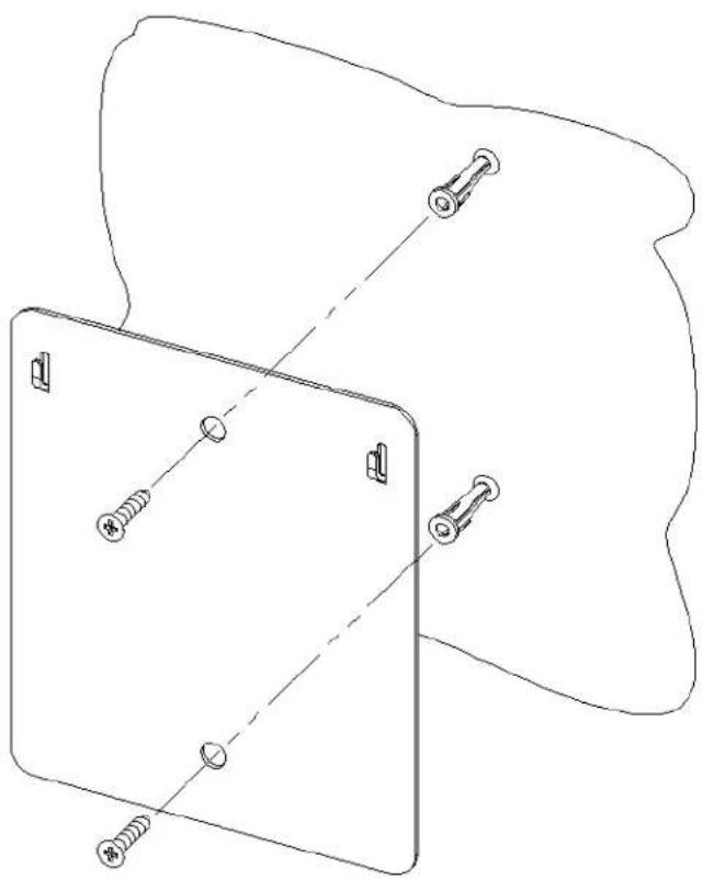
Figure 17: Mounting Wall Bracket
- Using hooks provided on bracket, position BSAP-1800. Notice the wall mount grooves on the back of the BSAP-1800 (see Figure 18).

Figure 18: Positioning BSAP-1800 on Hooks
Connecting and Powering the BSAP
Follow these instructions to connect your BlueSecure BSAP to your Bluesocket WLAN and then power it up:
-
Make a note of the 12-character MAC address and the serial number listed on the bottom of the BSAP before mounting the BSAP to a wall or other surface. You will need this information during configuration.
-
Position the BSAP-1800 for best radio performance.
The BSAP-1800 utilizes a 6-element MIMO antenna panel under the top cover of the unit. This antenna panel is made up of a combination of horizontally and vertically polarized antenna elements, which should give excellent performance regardless of the orientation of the AP. The BSAP-1800 should, however, be place where it has the best unobstructed view of the coverage area. If possible, mounting the BSAP-1800 on the ceiling will provide the best performance in a typical office environment. An optional ceiling tile mounting kit is available for the BSAP-1800, which provides for a very esthetically pleasing and professional looking installation. For more information, please refer to Bluesocket's web site.
- The BSAP derives its operating power directly from the RJ-45 connector when connected to a device that provides IEEE 802.3af compliant Power over Ethernet (PoE).

Caution: If the BSAP is used in a medical environment, it must use an IEC/EN60601-1 compliant power adapter. See page 24 for a description of the IEC/EN60601-1 compliant power adapter.
-
Verify that the PWR LED stops flashing and remains on, and that the other status LEDs start functioning as described in the section entitled "LED Indicators" on page 3.
-
Connect the BSAP to your Bluesocket WLAN.
You can connect the BSAP-1800 to a 10/100/1000 Mbps Ethernet through a network device such as a hub or a switch, or to a 1000BaseT Gigabit Ethernet interface. Connect the RJ-45 Ethernet connector on the BSAP's back panel to your network using category 3, 4, or 5 UTP Ethernet cable. When the BSAP and the connected device are powered on, the BSAP's Ethernet Link LED should light indicating a valid network connection.
Using the BSAP Command Line Interface (CLI)

Note: Normally you will not need to access the BSAP CLI. In a properly provisioned Bluesocket WLAN, the BSAP will automatically discover and communicate with its home BSC. We recommend that you use the CLI to configure the BSAP only in a lab or test environment, or where a pre-defined static IP address is desired.
You can connect a console to the BSAP's Ethernet port to perform local configuration of the BSAP using its command line interface (CLI). You can use the BSAP's CLI to manually configure:
- the BSAP's IP address
- the IP address of the home BSC from which the BSAP will download its configuration and software image
- Site survey mode
Accessing the BSAP CLI
Access the BSAP CLI using an SSH client (the example uses putty) For example:
-
The default management IP address for the AP-1800 is 192.168.190.1. Configure your laptop computer to have a static IP address in this same subnet, for example 192.168.190.2.
-
Ping the AP from the laptop to make sure it can be seen.
-
Configure putty to use SSH and then connect to the IP address of the AP (by default 192.168.190.1) on port 2335.
-
Enter the following username and password in lowercase at the displayed CLI login prompts:
BlueAP login: adm1n (i.e., adm "one" n) Password: blue1socket (i.e., blue "one" socket).
Navigating the BSAP CLI
The BSAP CLI main menu provides access to these options:

Figure 19: PuTTY Configuration
- Network Configuration - Configure the BSAP's network settings including its IP address and the IP address of the BSC to which it will connect.
- Save/Apply Configuration - After you have configured the BSAP's network settings, you must apply them before they become active.
- Restore Defaults - Restore the BSAP to its default settings.
• Show Version Information - Display BSAP version information. - Reboot AP - After applying the BSAP's configuration settings, you must reboot the BSAP to effect the new configuration.
- Site Survey Configuration - In site survey mode, the BSAP beacons known SSIDs on its 802.11a/n and 802.11 b/g/n radios operating at a configurable power level and channel to facilitate a WLAN site survey. Rebooting the BSAP following a site survey, restores the BSAP's existing configuration. See page 23 for details on using the BSAP's site survey mode.
When operating in a submenu, press h to return directly to the main menu (or home menu). Press p to return to the previous menu.
BSAP Default Configuration
The BSAP is shipped with the following default configuration.
IP_ADDR_MODE: DHCP (0)
IP_ADDR 0.0.0.0
NETMASK 0.0.0.0
GW_ADDR 0.0.0.0
DNS_ADDR 0.0.0.0
WG_ADDR_MODE Discover BSC (0)
WG_ADDR 0.0.0.0
MNGMT_IP_ADDR 192.168.190.1
The two options for IP address mode are:
• (0) DHCP - The BSAP runs a DHCP client and receives its IP address from a DHCP server.
• (1) Static IP - You assign the BSAP a static IP address via its CLI.
The two options for WG address mode are:
• (0) Discover - The BSAP automatically discovers the IP address of the BSC to which it is to connect.
• (1) Static Configuration - Using the BSAP CLI, you will configure the IP address of the BSC to which the BSAP is to connect.
Setting the BSAP and Home BSC IP Addresses Using the CLI
To set the BSAP and Home BSC IP addresses using the CLI:
- Enter 1 at the BSAP CLI main menu command prompt.
The BSAP CLI network configuration menu appears:

Figure 20: BSAP CLI Network Configuration Menu
- Enter 1 at the Network Cfg prompt to set the IP address mode.
Enter 1 to set the BSAP IP address mode to static.
- Enter 2 at the Network Cfg prompt to set the BSAP's IP address.
Enter the BSAP IP address and subnet mask using the format:
<address> netmask <netmask>
-
Enter 3 at the Network Cfg prompt to specify the BSAP's default IP gateway.
-
Enter 4 at the Network Cfg prompt to specify the IP address of the BSAP's primary DNS server.
-
Enter 5 at the Network Cfg prompt to specify the BSC mode, i.e. how the BSAP is to obtain the IP address of its home BSC.
You can set the BSC mode to either Discover or Static BSC.
Enter 1 to set the BSC mode to Static BSC.
- Enter 6 at the Network Cfg prompt to specify the IP address of the BSAP's home BSC.
- Enter 8 at the Network Cfg prompt to review the BSAP network configuration settings you have made.
The network summary includes the MAC addresses of the BSAP's Ethernet and wireless interfaces.
- Enter p at the CLI prompt to return to the main menu.
Enter 2 at the main menu to apply your configuration changes, reboot the BSAP, and put the new configuration settings into effect.
When the BSAP completes its reboot, it will connect to and download its configuration from the home BSC you have configured via the CLI.
Using the BSAP's Site Survey Mode
The BSAP provides a site survey mode that is useful when you are conducting a site survey to determine optimal RF coverage for your facility.
In site survey mode, the BSAP continually beacons the SSID
"site_survey_chn#_pwr#" from its 802.11a/n and 802.11 b/g/n radios at a rate of 100 milliseconds. Here are the options to configure site survey mode:
- Select Option "a" from the main menu to enter the site survey sub-menu.
- Select the Interface (11b/g/n or 11a/n) to configure. All the radio settings that are configured after this interface is setup will apply to the configured interface.
- Set Antenna Type (Doesn't apply to the 1800).
- Set Channel - channel to transmit the beacons.
- Set Transmit Power - transmit power of the beacons - levels 0-10.
- Enable Site Survey Mode – Once you setup the channel and transmit power, the settings are applied once you enable it with this option.
- Site Survey Summary – View your current site survey settings.
Rebooting the BSAP following a site survey, restores the BSAP's existing configuration.

Figure 21: BSAP CLI Network Configuration Menu
General Specifications
Power Supply
Standard
Input: AC100-240V\~, 50-60Hz, 0.5A
Output: DC48V, 0.31A
Input: +48VDC via wall adapter (BSAP-PWR-000-00-0) or Power Over Ethernet (POE).
Max power consumption: 250 mA @ 48 VDC, 12 Watts
Note: If the wall adapter applies power to the BSAP-1800 before the Power Sourcing Equipment (PSE), it prevents the PSE from detecting the BSAP-1800. If the PSE is already powering the BSAP-1800 when the wall adapter is plugged in, priority is given to the higher supply voltage.
PoE (DC)
Input voltage: 48 volts, 0.25 A, 12 watts (Class 3)
Note: Power can also be provided to the access point through the Ethernet port based on IEEE 802.3af Power over Ethernet (PoE) specifications.
Dimensions
Length: 9 in. (22.9 cm)
Width: 9in. (22.9 cm)
Height: 2 in. (5.1 cm)
Weight
2 lbs. (0.907 kilograms)
LED Indicators
PWR (Power), Ethernet Link (Ethernet Link/Activity), 802.11a/n wireless link and activity, 802.11b/g/n wireless link and activity, and (2) status indicators.
Network Management
The BSAP-1800 can be managed by any of the BlueSecure Controllers, BlueView Management System (BVMS), or through the BSAP-1800's Ethernet port via SSH.
Temperature
Operating: 0 to 55 °C (32 to 131 °F)
Storage: 0 to 70 °C (32 to 158 °F)
Wireless Communications
Wireless Speeds: 802.11b 1/2/5.5/11Mbps 802.11g 1/2/5.5/6/9/11/12/18/24/36/48/54 Mbps 802.11a 6/9/12/18/24/36/48/54 802.11n 6.5/13/13.5/19.5/26/27/39/40.5/52/78/81/104/108/117/130/ 162/216/243/270/300 Mbps
Modulation Type: DSSS, OFDM, BPSK, QPSK, CCK, 16QAM, 64QAM
Operating Frequency: 2.400\~2.4835GHz, 5.15\~5.25GHz & 5.725\~5.850GHz
Channel Numbers: 11 (for 2.4GHz Band); 8 for normal mode (for 5GHz Band)
Transmitter Output Power:
+22dBm (for 2.4GHz Band)
+20dBm (for 5.15\~5.25GHz Band)
+20dBm (for 5.725\~5.850GHz Band)
Compliance
Safety
UL 60950
CAN/CSA C22.2 No. 60950
IEC 60950
EN 60950
EMI & Susceptibility Class B
FCC Part 15.107 and 15.109
ICES-003 (Canada)
EN 301.489-1 and -17 (Europe)
EN60601-1-2
EN5502 & EN55024
EN6100-3-2, -3-3,
Radio Approvals
FCC Part 15.247 and 15.407
FCC ID Registration and ID Number
EN 300.328, EN 301.893 (Europe)
RSS-210 (Canada)
EU Notification Body Letter
Declarations of Conformity and Regulatory Information
FCC Radiation Exposure Statement
This equipment complies with FCC radiation exposure limits set forth for an uncontrolled environment. This equipment should be installed and operated with a minimum distance of 20 centimeters (8 inches) between the radiator (antenna) and your body.
This transmitter must not be co-located or operating in conjunction with any other antenna or transmitter.
Federal Communication Commission Interference Statement
This equipment has been tested and found to comply with the limits for a Class B digital device, pursuant to Part 15 of the FCC Rules. These limits are designed to provide reasonable protection against harmful interference in a residential installation. This equipment generates, uses and can radiate radio frequency energy and, if not installed and used in accordance with the instructions, may cause harmful interference to radio communications. However, there is no guarantee that interference will not occur in a particular installation. If this equipment does cause harmful interference to radio or television reception, which can be determined by turning the equipment off and on, the user is encouraged to try to correct the interference by one of the following measures:
- Reorient or relocate the receiving antenna.
- Increase the separation between the equipment and receiver.
- Connect the equipment into an outlet on a circuit different from that to which the receiver is connected.
- Consult the dealer or an experienced radio/TV technician for help.
This device complies with Part 15 of the FCC Rules. Operation is subject to the following two conditions: (1) This device may not cause harmful interference, and (2) this device must accept any interference received, including interference that may cause undesired operation.
FCC Caution: Any changes or modifications not expressly approved by the party responsible for compliance could void the user's authority to operate this equipment.
For operation within 5.15 \~ 5.25GHz frequency range, it is restricted to indoor environment.
IEEE 802.11b or 802.11g operation of this product in the U.S.A. is firmware-limited to channels 1 through 11.
Industry Canada Statement
Operation is subject to the following two conditions:
1) This device may not cause interference, and
2) this device must accept any interference, including interference that may cause undesired operation of the device.
This device has been designed to operate with an antenna having a maximum gain of 8 dB. Antenna having a higher gain is strictly prohibited per regulations of Industry Canada. The required antenna impedance is 50 ohms.
To reduce potential radio interference to other users, the antenna type and its gain should be so chosen that the EIRP is not more than required for successful communication.
Because high power radars are allocated as primary users (meaning they have priority) in 5250-5350 MHz, these radars could cause interference and/or damage to license exempt LAN devices.
This equipment complies with IC radiation exposure limits set forth for an uncontrolled environment. This equipment should be installed and operated with a minimum distance of 20 centimeters (8 inches) between the radiator (antenna) and your body.
This transmitter must not be co-located or operated in conjunction with any other antenna or transmitter.
Declaration of Conformity with Regard to the R&TTE Directive 1999/5/EC
| English: This equipment is in compliance with the essential requirements and other relevant provisions of Directive 1999/5/EC. | |
| Deutsch: Dieses | Gerät entspricht den grundlegenden Anforderungen und den weiteren entsprecheneden Vorgaben der Richtlinie 1999/5/EU. |
| Dansk: | Dette udstyr er i overensstemmelse med de væsentlige krav og andre relevante bestemmelser i Directiv 1999/5/EF. |
| Español: Este equipo cumple con los requisitos esenciales asi como con otras disposiciones de la Directive 1999/5/EC. | |
| Ελληνική: | Autóς ο εξοπλισμός είναι σε συμμόρφωση με τις ουσιώδεις απαιτήσεις και άλλες διατάξεις της Οδηγιας 1999/5/EC. |
| Français: Cet appareil est conforme aux exigencies essentialles et aux autres dispositions pertinantes de la Directive 1999/5/EC. | |
| Íslenska: Pessi búnăður samrýmist lögboðnum kröfum og öðrum ákvæðum tilskipunar 1999/5/ESB. | |
| Italiano: Questo apparato é conforme ai requisiti essenziali ed agli altri principi sanciti dalla Direttiva 1999/5/EC. | |
| Nederlands: Deze apparatuur voldoet aan de belangrijkste eisen en andere voorzieningen van richtlijn 1999/5/EC. | |
| Norsk: Dette utstyret er i samsvar med de grunnleggende krav og andre relevante bestemmelser i EU-directiv 1999/5/EC. | |
| Português: Este equipamento satisfaz os requisitos essenciais e outras provisões da Directiva 1999/5/EC. | |
| Suomalainen: Tämä laite täyttää direktiivin 1999/5/EY oleelliset vaatimukset ja on siinä asetettujen muidenkin ehtojen mukainen. | |
| Svenska: Denna utrustning är i överensstämmelse med de väsentliga kraven och andra relevanta bestämmelser i Direktiv 1999/5/EC. | |
The following standards were applied during the assessment of the product against the requirements of the Directive 1999/5/EC:
- Radio: EN 301 893 and EN 300 328 (if applicable)
- EMC: EN 301 489-1 and EN 301 489-17
- Safety: EN 60950 and EN 50385
Note: This equipment is intended to be used in all EU and EFTA countries. Outdoor use may be restricted to certain frequencies and/or may require a license for operation. For more details, contact Bluesocket, Inc.
National Restrictions
In the majority of the EU and other European countries, the 2.4- and 5-GHz bands have been made available for the use of wireless LANs. Table 2 provides an overview of the regulatory requirements that apply to the 2.4- and 5-GHz bands.
Later in this section you will find an overview of countries in which additional restrictions or requirements or both apply.
The requirements for any country may evolve. Cisco recommends that you check with local authorities for the latest status of their national regulations for both 2.4- and 5-GHz wireless LANs.
Table 2: Overview of Regulatory Requirements for Wireless LANs
| Frequency Band (MHz) | Max Power Level (EIRP)a(mW) | Indoor ONLY | Indoor and Outdoor |
| 2400-2483.5 | 100 | X | |
| 5150-53502b | 200 X | ||
| 5470-57251 | 1000 | X |
a. Effective isotropic radiated power (EIRP).
b. Dynamic Frequency Selection and Transmit Power Control is required in the 5250- to 5350-MHz and 5470- to 5725-MHz frequency range.
The following sections identify countries having requirements or restrictions in addition to those listed in Table 2.
Belgium
The Belgian Institute for Postal Services and Telecommunications (BIPT) must be notified of any outdoor wireless link having a range exceeding 300 meters. Bluesocket recommends checking http://www.bipt.be for more details.
For 2.4 GHz, the output power is restricted to 10 mW EIRP when the product is used outdoors in the band 2454 to 2483 MHz. There are no restrictions when used indoors or when used in other parts of the 2.4 GHz band. For 5 GHz, the frequency bands 5150 to 5350 MHz and 5470 to 5725 MHz will become fully available by November 1, 2005. Until then, only the band 5150 to 5350 MHz is available.
Check http://www.arcep.fr/ for more details.
A license from EETT is required for the outdoor operation in the band 5470 to 5725 MHz. Bluesocket recommends checking http://www.eett.gr for more details.
This product meets the National Radio Interface and the requirements specified in the National Frequency Allocation Table for Italy. Unless this wireless LAN product is operating within the boundaries of the owner's property, its use requires a "general authorization." Please check with http://www.comunicazioni.it/it/ for more details.
Note: Although Norway, Switzerland, and Liechtenstein are not EU member states, the EU Directive 1999/5/EC has also been implemented in those countries.
[Non-Text]
Note: The regulatory limits for maximum output power are specified in EIRP (radiated power). The EIRP level of a device can be calculated by adding the gain of the antenna used (specified in dBi) to the output power available at the connector (specified in dBm).
[Non-Text]
Countries within the EU with restricted use of the ISM Band frequency range include: CH, DE, DK, FR, FI, GB, IS, NO, NL, PT, SE, BE
Safety Warnings for BlueSecure™ Access Point 1800
This section provides translations of the following safety warnings for the BlueSecure™ Access Point 1800:
- Warning Definition
- Explosive Device Proximity Warning
- Antenna Installation Warning
- Power Source Warning
- Work During Lightning Activity Warning
- Installation Instructions Warning
- Circuit Breaker (20A) Warning
Warning Definition
| Warning | IMPORTANT SAFETY INSTRUCTIONSThis warning symbol means danger. You are in a situation that could cause bodily injury. Before you work on any equipment, be aware of the hazards involved with electrical circuitry and be familiar with standard practices for preventing accidents. Use the statement number provided at the end of each warning to locate its translation in the translated safety warnings that accompanied this device.SAVE THESE INSTRUCTIONS |
| Waarschuwing | BELANGRIUKE VEILIGHEIDSINSTRUCTIESDit waarschuwingssymbool betekent gevaar. U verkeert in een situatie die lichamelijk letsel kan veroorzaken. Voordat u aan enige apparatuur gaat werken, dient u zich bewust te zijn van de bij elektrische schakelingen betrokken risico's en dient u op de hoogte te zijn van de standaard praktijken om ongelukken te voorkomen. Gebruik het nummer van de verklaring onderaan de waarschuwing als u een vertaling van de waarschuwing die bij het apparaat wordt geleverd, wilt raadplegen.BEWAAR DEZE INSTRUCTIES |
| Varoitus TÄRKEITÄ TURVALLISUUSOHJEITATämä varoitusmerkki merkitsee vaaraa. Tilanne voi aiheuttaa ruumiillisia vammoja. Ennen kuin käsittelet laitteistoa, huomioi sähköpiirien käsittelemiseen liittyvät riskit ja tutustu onnettomuuksien yleisiin ehkäisytapoihin. Turvallisuusvaroitusten käännökset löytyvät laitteen mukana toimitettujen käännettyjen turvallisuusvaroitusten joukosta varoitusten lopussa näkyvien lausuntonumeroiden avulla.SÄILYTÄ NÄMÄ OHJEET | |
| Attention | IMPORTANTES INFORMATIONS DE SÉCURITÉCe symbole d'avertissement indique un danger. Vous vous trouvez dans une situation pouvant entraîner des blessures ou des dommages corporels. Avant de travailler sur un équipement, soyez conscient des dangers liés aux circuits électriques et familiarisez-vous avec les procédures couramment utilisées pour éviter les accidents. Pour prendre connaissance des traductions des avertissements figurant dans les consignes de sécurité traduites qui accompagnent cet appareil, référez-vous au numéro de l'instruction situé à la fin de chaque avertissement.CONSERVEZ CES INFORMATIONS |
| Warnung WICHTIGE SICHERHEITSHINWEISEDiesesWarnsymbol bedeutet Gefahr. Sie befinden sich in einer Situation, die zu Verletzungen führen kann. Machen Sie sich vor der Arbeit mit Geräten mit den Gefahren elektrischer Schaltungen und den üblichen Verfahren zur Vorbeugung vor Unfällen vertraut. Suchen Sie mit der am Ende jeder Warnung angegebenen Anweisungsnummer nach der jeweiligen Übersetzung in den übersetzten Sicherheitshinweisen, die zusammen mit diesem Gerät ausgeliefert wurden.BEWAHREN SIE DIESE HINWEISE GUT AUF. | |
| Avvertenza | IMPORTANTI ISTRUZIONI SULLA SICUREZZAQuesto simbolo di avvertenza indica un pericolo. La situazione potrebbe causare infortuni alle persone. Prima di intervenire su qualsiasi apparecchiatura, occorre essere al corrente dei pericoli relativi ai circuiti elettrici e conoscere le procedure standard per la prevenzione di incidenti. Utilizzare il numero di istruzione presente alla fine di ciascuna avvertenza per individuare le traduzioni delle avvertenze riportate in questo documento.CONSERVARE QUESTE ISTRUZIONI |
| Advarsel | VIKTIGE SIKKERHETSINSTRUKSJONERDette advarselssymbolet betyr fare. Du er i en situasjon som kan føre til skade på person. Før du begynner å arbeide med noe av utstyret, må du være oppmerksom på farene forbundet med elektriske kretser, og kjenne til standardprosedyrer for å forhindre ulykker. Bruk nummeret i slutten av hver advarsel for å finne oversettelsen i de oversatte sikkerhetsadvarslene som fulgte med denne enheten.TA VARE PÅ DISSE INSTRUKSJONENE |
| Aviso | INSTRUÇÕES IMPORTANTES DE SEGURANÇAEste símbolo de aviso significa perigo. Você está em uma situação que poderá ser causadora de lesões corporais. Antes de iniciar a utilização de qualquer equipamento, tenha conhecimento dos perigos envolvidos no manuseio de circuitos elétricos e familiarize-se com as práticas habituais de prevenção de acidentes. Utilize o número da instrução fornecido ao final de cada aviso para localizar sua tradução nos avisos de segurança traduzidos que acompanham este dispositivo.GUARDE ESTAS INSTRUÇÕES |
| ¡Advertencial | INSTRUCCIONES IMPORTANTES DE SEGURIDADEste símbolo de aviso indica peligro. Existe riesgo para su integridad física. Antes de manipular cualquier equipo, considere los riesgos de la corriente eléctrica y familiarícese con los procedimientos estándar de prevención de accidentes. Al final de cada advertencia encontrará el número que le ayudará a encontrar el texto traducido en el apartado de traducciones que acompaña a este dispositivo.GUARDE ESTAS INSTRUCCIONES |
| Vaming! | VIKTIGA SÄKERHETSANVISNINGARDenna varningssignal signalerar fara. Du befinner dig i en situation som kan leda till personskada. Innan du utför arbete på någon utrustning måste du vara medveten om farorna med elkretsar och känna till vanliga förfaranden för att förebygga olyckor. Använd det nummer som finns i slutet av varje varning för att hitta dess översättning i de översatta säkerhetsvarningar som medföljer denna anordning.SPARA DESSA ANVISNINGAR |
| Figyelem | FONTOS BIZTONSÁGI ELOÍRÁSOKEz a figyelmezeto jel veszélyre utal. Sérülésveszélyt rejto helyzetben van. Mielott bármely berendezesen munkát végazte, legyen figyelemmel az elektromos áramkörök okozta kockázatokra, és ismerkedjen meg a szokásos balesetvédelmi eljárásokkal. A kladványban szerepilo figyelmeztetések fordítása a készülékhez mellékelt biztonsági figyelmeztetések között található; a fordítás az egyes figyelmeztetések végén látható szám alapján keresheto meg.ORIZZE MEG EZEKET AZ UTASÍTÁSOKAT! |
| Предупреждение | ВАЖНЫЕ ИНСТРУКЦИИ ПО СОБЛЮДЕНИЮ ТЕХНИКИ БЕЗОПАСНОСТИЭтот символ предупреждения обозначает опасность. То есть имеет место ситуация, в которой следует опасаться теплесных повреждений. Перед эксплуатацией оборудования выясните, каким опасностям может подвергаться пользователь при использовании электрических цепой, и ознакомьтесь с правилами техники безопасности для предотвращения возможных несчастных случаев. Воспользуйтесь номером заявления, приведенным в конце каждого предупреждения, чтобы найти его переведенный вариант в переводе предупреждений по безопасности, прилагаемом к данному устройству.СОХРАНИТЕ ЭТИ ИНСТРУКЦИИ |
| 警告 | 重要的安全性说明此警告符号代表危险。您正处于可能受到严重伤害的工作环境中。在您使用设备开始工作之前,必须充分意识到触电的危险,并熟练掌握防止事故发生的标准工作程序。请根据每项警告结尾提供的声明号码来找到此设备的安全性警告说明的翻译文本.请保存这些安全性说明 |
| 警告 | 安全上の重要な注意事项「危険」の意味です。人身事故を予防するための注意事項が記述されています。装置の取り扱い作業を行うときは、電気回路の危険性に注意し、一般的な事故防止策に留意してください。警告の各国語版は、各注意事項の番号を基に、装置に付属の「Translated Safety Warnings」を参照してください。これらの注意事項を保管しておいてください。 |
| 주의 | 중요 인전 지침이 경고 가르는 위험을 나타됩니다. 적임자가 신체 부상을 입으킬 수 있는 위험한 환경에 있습니다. 징비에 직업을 수행하기 전에 전기 회로와 관련된 위험을 속지하고 펜준 작업 관례를 속지하여 사고를 방지하십시오. 각 경고의 마지막 부분에 있는 경고문 번호를 참조하여 이 장치와 함께 제공되는 번역된 인전 경고문에서 해당 번역문을 맞으십시오.이 지시 사항을 보관하십시오. |
| Aviso INSTRUÇÕES IMPORTANTES DE SEGURANÇAEste símbolo de aviso significa perigo. Você se encontra em uma situação em que há risco de lesões corporais. Antes de trabalhar com qualquer equipamento, esteja ciente dos riscos que envolvem os circuitos elétricos e familiarize-se com as práticas padrão de prevenção de acidentes. Use o número da declaração fornecido ao final de cada aviso para localizar sua tradução nos avisos de segurança traduzidos que acompanham o dispositivo.GUARDE ESTAS INSTRUÇÕES | |
| Advarsel VIGTIGE SIKKERHEDSANVISNINGERDette advarselssymbol betyder fare. Du befinder dig i en situation med risiko for legemesbeskadigelse. Før du begynder arbejde på udstyr, skal du være opmærksom på de involverede risici, der er ved elektriske kredsløb, og du skal sætte dig ind i standardprocedurer til undgåelse af ulykker. Brug erklæringsnummeret efter hver adversel for at finde oversættelsen i de oversatte advarsler, der fulgte med denne enhed.GEM DISSE ANVISNINGER | |
| تحذير | إرشادات autocман العامةyostrag رمز التحذير هذا وجود خطر. weekendها JEINI アイドミ تتواجد في مكان قد يптجع Entه الت express للا�ابات. قبلuidء العمل.احذر مخاطر الت express للصدمة الكهربائيةorencongen ongi MLا اجراءات قدياسية للحيولة دون و Missouriت. استخدمرقم Calibration Woodwood في أخركل ت SGDIR لADDID MEKAN TRGIMTE DA CLI TCGDIBRAT AMAAN MTRJMEA THI TATNI MOG JHEIAZ.QCM بح Netflix هزده الإرشادات |
Explosive Device Proximity
| Warning | Do not operate your wireless network device near unshielded blasting caps or in an explosive environment unless the device has been modified to be especially qualified for such use. |
| Waarschuwing | Gebruik dit draadloos netwerkapparaat alleen in de buurt van onbeschermde ontstekers of in een omgeving met explosieven indien het apparaat speciaal is aangepast om aan de eisen voor een dergelijk gebruik te voldoen. |
| Varoitus | Älä käytä johdotonta verkkolaitetta suojaamattomien räjäytysnallien läheisyydessä tai räjäytysalueella, jos laitetta ei ole erityisesti muunnettu sopivaksi sellaiseen käyttöön. |
| Attention | Ne jamais utiliser un équipement de réseau sans fil à proximité d'un détonateur non blindé ou dans un lieu présentant des risques d'explosion, sauf si l'équipement a été modifié à cet effet |
| Wamung Benutzen Sie Ihr drahtloses Netzwerkgerät nicht in der Nähe ungeschützter Sprengkapseln oder anderer explosiver Stoffe, es sei denn, Ihr Gerät wurde eigens für diesen Gebrauch modifiziert und bestimmt. | |
| Avvertenza | Non utilizzare la periferica di rete senza fili in prossimità di un detonatore non protetto o di esplosivi a meno che la periferica non sia stata modificata a tale proposito. |
| Advarsel | Ikke bruk den trådløse nettverksenheten nært inntil uisolerte fenghetter eller i et eksplosivt miljø med mindre enheten er modifisert slik at den tåler slik bruk. |
| Aviso | Não opere o dispositivo de rede sem fios perto de cápsulas explosivas não protegidas ou num ambiente explosivo, a não ser que o dispositivo tenha sido modificado para se qualificar especialmente para essa utilização. |
| ¡Advertencia! | No utilizar un aparato de la red sin cable cerca de un detonador que no esté protegido ni tampoco en un entorno explosivo a menos que el aparato haya sido modificado con ese fin. |
| Varning! | Använd inte den trådlösa nätverksenheten i närheten av oskyddade tändhattar eller i en explosiv miljø om inte enheten modifierats för att kunna användas i sådana sammanhang. |
Antenna Installation Warning
| Warning | In order to comply with FCC radio frequency (RF) exposure limits, antennas should be located at a minimum of 7.9 inches (20 cm) or more from the body of all persons. |
| Waarschuwing | Om te voldoen aan de FCC radiofrequentie (RF) blootstellingslimieten dienen antennes zich minstens 20 cm of meer van de lichamen van alle personen bevinden. |
| Varoitus | FCC:n antamien radiotaajuksille altistumista koskevien rajoitusten mukaan antennien on sijaittava vähintään 20 cm:n päässä kaikista henkilöistä. |
| Attention | Pour se conformer aux limites d'exposition à la fréquence radio préconisées par la FCC (Federal Communications Commission), les antennes doivent se situer à un minimum de 20 cm de toute personne. |
| Warnung | Um die in den FCC-Richtlinien festgelegten Expositionshöchstgrenzen für Radiofrequenzen (RF) nicht zu überschreiten, sollten Antennen mindestens 20 cm entfernt von Personen aufgestellt werden. |
| Avvertenza | Per conformarsi ai limiti FCC di esposizione a radiofrequenza (RF), le antenne devono stare ad una distanza minima di 20 cm dal corpo di ogni persona. |
| Advarsel | I henhold til eksponeringsgrensene for radiofrekvenser (RF), skal antenner befinne seg på en avstand av minst 20 cm eller mer fra mennesker. |
| Aviso P | Para estar de acordo com as normas FCC de limites de exposição para frequência de rádio (RF), as antenas devem estar distantes no mínimo 20 cm (7,9 pol) do corpo de qualquer pessoa. |
| ¡Advertencial! | Para cumplir con los límites de exposición de radio frecuencia (RF) de la Comisión Federal de Comunicaciones (FCC) es preciso ubicar las antenas a un mínimo de 20 cm (7,9 pulgadas) o más del cuerpo de las personas. |
| Varning! | För att följa FCC-exponeringsgränserna för radiofrekvens (RF), bör antenner placeras på minst 20 cm avständ från alla människor. |
Power Source Warning
| Warning | This product must be connected to a Power over Ethernet (PoE) IEEE 802.3af compliant power source or an IEC60950 compliant limited power source. |
| Waarschuwing | Dit product moet worden verbonden met een stroomvoorziening die compatibel is met PoE (Power over Ethernet) IEEE 802.3af of een beperkte stroomvoorziening die compatibel is met IEC60950. |
| Varoitus | Tämä tuote on liitettävä PoE (Power over Ethernet) IEEE 802.3af - yhteensopivaan virtalähteeseen tai IEC60950-yhteensopivaan rajoitettuun virtalähteeseen. |
| Attention | Ce produit doit être connecté à une source d'alimentation électrique par câble Ethernet (PoE) conforme à la norme IEEE 802.3af ou à une source d'alimentation limitée conforme à la norme IEC60950. |
| Warnung | Dieses Produkt muss entweder an eine Stromquelle angeschlossen sein, die mit dem IEEE 802.3af-Standard Power over Ethernet (PoE) kompatibel ist oder an eine Stromquelle für geringe Leistungen, die IEC60950-kompatibel ist. |
| Avvertenza | Questo prodotto deve essere connesso a una fonte di alimentazione di tipo PoE (Power over Ethernet) conforme a IEEE 802.3af o a una fonte di alimentazione conforme a IEC60950. |
| Advarsel | Dette produktet må være koblet til en Power over Ethernet (PoE) IEEE 802.3af-kompatibel strømkilde eller en IEC60950-kompatibel begrenset strømkilde. |
| Aviso | Este produto tem de estar ligado a uma fonte de alimentação compatível com a norma IEEE 802.3af, também conhecida pela sigla Power over Ethernet (PoE), ou a uma fonte de alimentação limitada compatível com a norma IEC60950. |
| jAdvertencial | Debe conectar este producto a una fuente de alimentación sobre ethernet (PoE) conforme con el estándar IEEE 802.3af, o a una fuente limitada conforme con el estándar IEC60950. |
| Varning! | Denna produkt måste vara ansluten till en PoE IEEE 802.3af-kompatibel strömkälla eller en IEC60950-kompatibel begränsad strömkälla. |
| Figyelem | Ezt a készüléket vagy az IEEE 802.3af szabványnak megfelelő, a tápellátást Etherneten keresztül kapó (power-over-ethernet, PoE) tápforráshoz, vagy az IEC60950 szabványnak megfelelő, korlátozott tápforráshoz kell csatlakoztatni. |
| Предупреждение | Это устройство может быть подключено к источнику питания для подачи питания по сети Ethernet (PoE), удовлетворяющему требованиям стандарта IEEE 802.3af, или источнику питания ограниченного применения, удовлетворяющему требованиям стандарта IEC60950. |
| 警告 | 本产品必須连接到以太网供电型(Power-Over-Ethernet, 简称PoE) IEEE802.3af 电源或 IEC80950 限制型电源。 |
| 警告 | この製品はPoE方式の IEEE 802.3af対応の電源またはIEC60950対応の制限電源に接続してください。 |
Work During Lightning Activity Warning
| Waming | Do not work on the system or connect or disconnect cables during periods of lightning activity. |
| Waarschuwing | Tijdens onweer dat gepaard gaat met bliksem, dient u niet aan het systeem te werken of kabels aan te sluiten of te ontkoppelen. |
| Varoitus | Älä työskentele järjestelmän parissa äläkä yhdistä tai irrota kaapeleita ukkosilmalla. |
| Attention | Ne pas travailler sur le système ni brancher ou débrancher les câbles pendant un orage. |
| Wamung | Arbeiten Sie nicht am System und schließen Sie keine Kabel an bzw. trennen Sie keine ab, wennes gewittert. |
| Avvertenza | Non lavorare sul sistema o collegare oppure scollegare i cavi durante un temporale con fulmini. |
| Advarsel | Utfør aldri arbeid på systemet, eller koble kabler til eller fra systemet når det tordner eller lyner. |
| Aviso | Não trabalhe no sistema ou ligue e desligue cabos durante períodos de mau tempo (trovoada). |
| ¡Advertencial! | No operar el sistema ni conectar o desconectar cables durante el transcurso de descargas eléctricas en la atmósfera. |
| Vaming! Vid | åska skall du aldrig utföra arbete på systemet eller ansluta eller koppla loss kablar. |
| Figyelem | Villámlás közben ne dolgozzon a rendszeren, valamint ne csatlakoztasson és ne húzzon ki kábeleket! |
| Предупреждение | Не следует работать с устройством, а также подключать или отключать кабели во время грозы |
| 警告 | 请勿在发生雷电时操作系统,也不要在此期间连接或断开电缆。 |
| 警告 | 雷が発生しているときは、システムに手を加えたり、ケーブルの接続や取り外しを行わないでください。 |
Installation Instruction Warning
| Warning | Read the installation instructions before connecting the system to the power source. |
| Waarschuwing | Raadpleeg de installatie-instructies voordat u het systeem op de voedingsbron aansluit. |
| Varoitus | Lue asennusohjeet ennen järjestelmän yhdistämistä virtalähteeseen. |
| Attention | Avant de brancher le système sur la source d'alimentation, consulter les directives d'installation. |
| Wamung Vor dem Anschließen des Systems an die Stromquelle die Installationsanweisungen lesen. | |
| Avvertenza Consultare le istruzioni di installazione prima di collegare il sistema all'alimentatore. | |
| Advarsel | Les installasjonsinstruksjonene før systemet kobles til strømkilden. |
| Aviso Leia as instruções de instalação antes de ligar o sistema à fonte de energia. | |
| ¡Advertencia! | Lea las instrucciones de instalación antes de conectar el sistema a la red de alimentación. |
| Varning! | Lös installationsanvisningarna innan du kopplar systemet till strömförsörjningsenheten. |
| Figyelem | Mielött áramforráshoz csatlakoztatná a rendszert, olvassa el az üzembe helyezési útmutatót! |
| Предупреждение | Перед подключением устройства к источнику электропитания сзнакомьтесь с данной инструкцией по установке. |
| 警告 | 在将系统与电源连接之前·请仔细阅读安装说明· |
| 警告 | 必ず設置手順を読んでから、システムを電源に接続してください。 |
Circuit Breaker (20A) Warning
| Warning | This product relies on the building's installation for short-circuit (overcurrent) protection. Ensure that the protective device is rated not greater than: 20A. |
| Waarschuwing | Dit product is afhankelijk van de installatie van het gebouw voor beveiliging tegen kortsluiting (overstroom). Controleer of de beschermingsinrichting niet meer dan: 20A is. |
| Varoitus Tämä tuote on riippuvainen rakennukseen asennetusta oikosulkusuojauksesta (ylivirtasuojauksesta). Varmista, että suojalaitteen mitoitus ei ole yli: 20A. | |
| Attention | Pour ce qui est de la protection contre les courts-circuits (surtension), ce produit dépend de l'installation électrique du local. Vérifiez que le courant nominal du dispositif de protection n'est pas supérieur à : 20A. |
| Warnung | Dieses Produkt ist darauf angewiesen, dass im Gebäude ein Kurzschluss-bzw. Überstromschutz installiert ist. Stellen Sie sicher, dass der Nennwert der Schutzvorrichtung nicht mehr als: 20A beträgt. |
| Avvertenza | Questo prodotto dipende dall'impianto dell'edificio per quanto riguarda la protezione contro cortocircuiti (sovracorrente). Assicurarsi che il dispositivo di protezione non abbia un rating superiore a: 20A. |
| Advarsel | Dette produktet er avhengig av bygningens installasjoner av kortslutnings (overstrøm)-beskyttelse. Påse at verneenheten ikke er merket høyere enn: 20A. |
| Aviso | Este produto depende das instalações existentes para proteção contra curto-circuito (sobrecarga). Assegure-se de que o fusível ou disjuntor não seja superior a: 20A. |
| ¡Advertencia! | Este equipo utiliza el sistema de protección contra cortocircuitos (o sobrecorrientes) del edificio. Asegúrese de que el dispositivo de protección no sea superior a: 20A. |
| Varning! | Denna produkt är beroende av i byggnaden installerat kortslutningsskydd (överströmsskydd). Kontrollera att skyddsanordningen inte har högre märkvärde än: 20A. |
| Figyelem | A termék védelmi rendezerének része az épület kábelezésébe épített rövidzárlat (túláram) ellení védelem is. Gondoskodjon róla, hogy a készüléket védő eszköz legfeljebb a következő aramerösségre legyen méretezve: 20A |
| Предупреждение | Защита устройства от короткого замыкания (перегрузки) осуществляется с помощью оборудования, являющегося частью электропроводки здания. Убедитесь, что номинал защитного устройства не превышает: 20A |
| 警告 | 此产品的短路(过载电流)保护由建筑物的供电系统提供・确保短路保护设备的额定电流不大于: 20A |
| 警告 | この製品は、設置する建物にショート(過電流)保護機構が備わっていることを前提に設計されています。保護装置の定格が以下の値を超えないことを確認してください。20A |


- BLUESECURE™ ACCESS POINT 1800 INSTALLATION GUIDE
- COPYRIGHT NOTICE
- TRADEMARKS
- CONTENTS
- OVERVIEW
- FAMILIARIZING YOURSELF WITH THE BSAP HARDWARE
- FIXED ANTENNAS
- LED INDICATORS
- ETHERNET/POE CONNECTOR
- RESET BUTTON
- KENSINGTON SECURITY SLOT
- PROVISIONING YOUR BLUESOCKET WLAN FOR BSAPS
- DEPLOYING BSAPS ON THE SAME LAYER-2 SUBNET AS THE BSC
- DEPLOYING BSAPS WITH LAYER-3 CONNECTIVITY TO THE BSC
- SELECTING A BSAP INSTALLATION LOCATION
- MOUNTING THE BSAP
- DROPPED CEILING TOOL REQUIREMENTS
- CONVENTIONAL CEILING TOOL REQUIREMENTS
- MOUNTING KIT CONTENTS
- DROPPED CEILING KIT INSTALLATION
- CEILING KIT INSTALLATION
- MOUNTING ON A WALL
- CONNECTING AND POWERING THE BSAP
- USING THE BSAP COMMAND LINE INTERFACE (CLI)
- ACCESSING THE BSAP CLI
- NAVIGATING THE BSAP CLI
- BSAP DEFAULT CONFIGURATION
- SETTING THE BSAP AND HOME BSC IP ADDRESSES USING THE CLI
- USING THE BSAP'S SITE SURVEY MODE
- GENERAL SPECIFICATIONS
- POWER SUPPLY
- POE (DC)
- DIMENSIONS
- WEIGHT
- NETWORK MANAGEMENT
- TEMPERATURE
- WIRELESS COMMUNICATIONS
- COMPLIANCE
- DECLARATIONS OF CONFORMITY AND REGULATORY INFORMATION
- FCC RADIATION EXPOSURE STATEMENT
- FEDERAL COMMUNICATION COMMISSION INTERFERENCE STATEMENT
- INDUSTRY CANADA STATEMENT
- NATIONAL RESTRICTIONS
- BELGIUM
- SAFETY WARNINGS FOR BLUESECURE™ ACCESS POINT
Brand : Adtran
Model : BlueSecure 1800
Category : Access Point