
Eden Vb - Central heating boiler Halstead - Free user manual and instructions
Find the device manual for free Eden Vb Halstead in PDF.


| Product Type | Central Heating Boiler |
| Brand | Halstead |
| Model | Eden Vb |
| Height | 700 mm |
| Width | 400 mm |
| Depth | 300 mm |
| Weight | 30 kg |
| Power Supply | 230 V ~ 50 Hz |
| Electrical Power Consumption | 120 W |
| Heat Output Range | 10 - 24 kW |
| Energy Efficiency Class | A (ErP Directive) |
| Main Functions | Central heating and domestic hot water |
| Control System | Electronic thermostat with timer |
| Maintenance | Annual service by qualified engineer |
| Cleaning | Wipe casing with dry cloth; do not use abrasives |
| Safety Features | Overheat protection, frost protection, pressure relief valve |
| Spare Parts Availability | Common parts available through Halstead distributors |
| Repairability Index | 7.5 / 10 |
| Installation Type | Wall-mounted |
| Suitable For | Residential central heating systems |
Frequently Asked Questions - Eden Vb Halstead
User questions about Eden Vb Halstead
0 question about this device. Answer the ones you know or ask your own.
Ask a new question about this device
Download the instructions for your Central heating boiler in PDF format for free! Find your manual Eden Vb - Halstead and take your electronic device back in hand. On this page are published all the documents necessary for the use of your device. Eden Vb by Halstead.
USER MANUAL Eden Vb Halstead
Instructions for Use
Installation and Servicing
To be left with the user
Eden Vb
G.C. No. 41-260-09
High Efficiency
Condensing Boiler


The code of practice for the installation, commissioning & servicing of gas central heating
This is a Cat I2H Appliance
Reference in these instructions to British Standards and Statutory Regulations/Requirements apply only to the United Kingdom.
For Ireland the current edition of I.S.813
"Domestic Gas Installations" must be used.

11687
The instructions consist of three parts, User, Installation and Servicing Instructions, which includes the Guarantee Registration Card. The instructions are an integral part of the appliance and must, to comply with the current issue of the Gas Safety (Installation and Use) Regulations, be handed to the user on completion of the installation.
Important Information
General
This boiler is designed to provide central heating from a fully pumped open-vented or sealed water system with a fully indirect cylinder.
The central heating water temperature can be adjusted on the boiler.
Once the controls are set the boiler operates automatically.
A frost protection program is also included.
Please read these instructions and follow them carefully for the correct and economical use of your boiler.
Gas Category
This boiler is for use only on Natural gas (G20).
Gas Safety (Installation and Use) Regulations
In your own interests and that of safety, it is the Law that ALL gas appliances are installed by a competent person in accordance with the current issue of the above regulations.
Gas Testing and Certification
The boiler is tested and certificated for safety and performance. It is, therefore, important that no alteration is made to the boiler unless approved, in writing, by Halstead Boilers Ltd.
Any alteration not approved by Halstead Boilers Ltd., could invalidate the certification, boiler warranty and may also infringe the current issue of the statutory requirements.
CE Mark
This boiler meets the requirements of Statutory Instrument, No. 3083 The Boiler (Efficiency) Regulations, and therefore is deemed to meet the requirements of Directive 92/42/EEC on the efficiency requirements for new hot water boilers fired with liquid or gaseous fuels.
Type test for purposes of Regulation 5 certified by: Notified body 0086.
Product/production certified by: Notified body 0086.
The CE mark on this appliance shows compliance with:
-
Directive 90/396/EEC on the approximation of the laws of the Member States relating to appliances burning gaseous fuels.
-
Directive 73/23/EEC on the harmonisation of the Laws of the Member States relating to electrical equipment designed for use within certain voltage limits.
- Directive 89/336/EEC on the approximation of the Laws of the Member States relating to electromagnetic compatibility.
Control of Substances Hazardous to Health
Under Section 6 of The Health and Safety at Work Act 1974, we are required to provide information on substances hazardous to health.
The adhesives and sealants used in this appliance are cured and give no known hazard in this state.
Insulation Pads
These can cause irritation to skin, eyes and the respiratory tract.
If you have a history of skin complaint you may be susceptible to irritation. High dust levels are usual only if the material is broken.
Normal handling should not cause discomfort, but follow normal good hygiene and wash your hands before eating, drinking or going to the lavatory.
If you do suffer irritation to the eyes or severe irritation to the skin seek medical attention.
Spare Parts
REMEMBER, When replacing a part on this appliance, use only spare parts that you can be assured conform to the safety and performance specification that we require. Do not use reconditioned or copy parts that have not been clearly authorised by Halstead Boilers Ltd.
Manual Handling Guidance
During the appliance installation and the replacement of the heat exchanger it will be necessary to employ caution and assistance whilst lifting as the appliance or component exceeds the recommended weight for a one man lift.
In certain situations it may be required to use a mechanical handling aid.
Take care to avoid trip hazards, slippery or wet surfaces.
| CONTENTS DESCRIPTION SECTION PAGE No. | |||
| INSTRUCTIONSFOR USE | Important information 2Operating the Boiler 4 | ||
| INSTALLATIONINSTRUCTIONS | General Information 1 5Water System 2 7Boiler Location and Ventilation 3 10Flue Location and Ventilation 4 11Installation Preparation 5 13Boiler Fixing 6 14Gas, Water and Condensate Conns. 7 15Flue Preparation and Installation 8 16Electrical Connections 9 18Commissioning 10 20 | ||
| SERVICINGINSTRUCTIONS | ServicingFault FindingReplacement of Parts 13 27Spare Parts | 111214 | 212532 |
Important Information
WARNINGS
Gas Leak or Fault
If a gas leak or fault exists or is suspected, turn the boiler mains electrical supply off and turn off the gas supply at the meter. Consult your local gas company or your local installation/servicing company.
Clearances
If fixtures are positioned close to the boiler, space must be left as shown in diagram 3.1. Enough space must also be left in front of the boiler to allow for servicing.
Sheet Metal Parts
This boiler contains metal parts (components) and care should be taken when handling and cleaning, with particular regard to edges.
Sealed Components
Under no circumstances must the User interfere with any sealed component as this could result in a potentially dangerous situation arising.
Electrical Supply Failure
This boiler must be earthed.
The boiler will not work without an electrical supply.
Normal operation of the boiler should resume when the electrical supply is restored.
Reset any external controls, to resume normal operation of the central heating.
If the boiler does not resume normal operation turn the mains reset switch off and on. If the boiler does not resume normal operation after this the overheat stat may have operated. The overheat stat would only operate under abnormal conditions and, under these circumstances; it would be advisable to consult your installation / servicing company.
Protection Against Freezing
The boiler has a built in frost protection programme as long as the electricity and gas are left switched on.
This device operates the burner and system pump when the temperature inside the boiler falls to 3° C.
Any other exposed areas of the system should be protected by a separate frost thermostat.
If the mains electricity and gas are to be turned off for any long periods during severe weather, it is recommended that the whole system, including the boiler, should be drained to avoid the risk of freezing. Make sure that, if fitted, the immersion heater in the cylinder is switched off.
If you have a sealed water system contact your installation/servicing company as draining, refilling and pressurising MUST be carried out by a competent person.
As a safety feature the boiler will stop working if the condensate drain becomes blocked. During freezing conditions this may be due to the forming of ice in the condense drain external to the house. Release an ice blockage by the use of warm cloths on the pipe. The boiler should then restart. Contact your installation/servicing company if the fault persists.
Boilers Installed in a Compartment or Cupboard
If the boiler is fitted into a compartment or cupboard it does not require ventilation openings.
Do not use the compartment or cupboard for storage.
Boiler Casing
Do not remove or adjust the casing in any way, as incorrect fitting may result in incorrect operation or failure to operate at all.
Condensate Drain
The condensate drain, see section 7.3, must not be modified or blocked.
Pluming from flue terminal
Like all condensing boilers this appliance will produce a plume of condensation from the flue terminal in cool weather. This is due to the high efficiency and hence low flue gas temperature of the boiler. It is normal and not a fault indication.
Cleaning
This appliance contains metal parts and care should be taken when handling and cleaning with particular regard to edges.
The boiler casing can be cleaned using a mild liquid detergent with a damp cloth, then a dry cloth to polish.
Do not use any form of abrasive or solvent cleaner as you may damage the paintwork.
Maintenance and Servicing
For the continued efficient and safe operation of the boiler it is recommended that it is checked and serviced at regular intervals. The frequency of servicing will depend upon the installation conditions and usage, but in general, once a year should be enough.
If this appliance is installed in a rented property in the UK there is a duty of care imposed on the owner of the property by the current issue of The Gas Safety (Installation and Use) Regulations, Section 35.
Servicing/maintenance should be carried out by a competent person in accordance with the rules in force in the countries of destination.
To obtain service, please call your installer or Halstead Boilers using the telephone number on the front cover of this booklet.
Please be advised that the installation engineer on completion of commissioning and servicing should complete the 'Benchmark' logbook.
All CORGI Registered Installers carry a CORGI ID card, and have a registration number. Both should be recorded in your boiler Logbook. You can check your installer is CORGI registered by calling CORGI direct on: - 01256 372300.
Replacement Parts
If replacement parts are required contact Halstead Boilers using the telephone number on the front cover of this booklet.
Please quote the name of the appliance, this information will be on the name badge on the front of the appliance.
If in doubt seek advice from the local gas company or Halstead Boilers using the telephone number on the front cover of this booklet.
Operating the Boiler
To Operate the Boiler
Sealed Water Systems.
CAUTION. A sealed water system must be filled and pressurised by a competent person.
Only light the boiler when you are sure that the system and boiler have been filled and pressurised.
The pressure should read at least 0.7 bar, anything less than this figure could indicate a leak and you MUST contact your installation / servicing company.
All Systems
Check that the electrical supply to the boiler is ON at the external isolator.
Set any remote controls as required.
User Controls
Turn the mains reset switch to the ON position. The control light will illuminate (green) indicating the boiler is lit, see diagram 1.
The temperature of the central heating water can be adjusted by turning the water temperature control knob to desired setting between I 'Min' and Max', see diagram 1.
'Max' is approximately 82°C (180°F)
Note: If the appliance is supplying DHW via a storage cylinder, the flow temperature should be set at a temperature high enough to satisfy the DHW demand temperature, for example 50 - 60°C.
The digital display, see diagram 1, shows the temperature of the appliance.
A fault is indicated by a RED flashing control light and flash fault code on digital display.
To reset:
Turn the mains reset switch anti-clockwise to 0.
Wait for 5 seconds.
Turn mains reset switch clockwise to I.
If the fault persists contact your installer/service provider.
It should be noted that this is a fan flue appliance and fan operation may be heard.
To Turn the Boiler Off
There is a mains reset switch on the right hand side of the controls fascia. However, it is preferable to leave the electrical supply on whenever possible to permit operation of the built-in frost protection and daily pump exercise.

1 General Information

IMPORTANT NOTICE
The boiler is supplied in one pack, the flue is supplied separately.
This boiler is for use only on G20 natural gas.
Where no British Standards exists, materials and equipment should be fit for their purpose and of suitable quality and workmanship.
Refer to Manual Handling Operations, 1992 regulations.
The installation of this boiler must be carried out by a competent person in accordance with the rules in force in the countries of destination.
Manufacturer's instructions must not be taken as overriding statutory requirements.
1.1 Sheet Metal Parts
WARNING: When installing the appliance, care should be taken to avoid any possibility of personal injury when handling sheet metal parts.
1.2 Statutory Requirements
The appliance is suitable only for installation in GB and IE and should be installed in accordance with the rules in force.
Draw attention, if applicable, to the current issue of the Gas Safety (Installation and Use) Regulations, Section 35, which imposes a duty of care on all persons who let out any property containing a gas appliance in the UK.
In GB the installation of the boiler must be carried out by a competent person as described in the following regulations:
The manufacturer's instructions supplied.
The Gas Safety (Installation and Use) Regulations.
The appropriate Buildings Regulations either The Building Regulations, The Building Regulations (Scotland), The Building Regulations (Northern Ireland).
The Water Fittings Regulations or Water byelaws in Scotland.
The Health and Safety at Work Act, Control of Substances Hazardous to Health (COSHH).
The Current I.E.E. Wiring Regulations.
Where no specific instructions are given, reference should be made to the relevant British Standard Code of Practice.
In IE, the installation must be carried out by a competent person and installed in accordance with the current edition of I.S.813 "Domestic Gas Installations", the current Building Regulations and reference should be made to the current ETCI rules for Electrical Installation.
In GB the following Codes of Practice apply:
BS4814, BS6798, BS5440 Part 1 and 2, BS5546 Part 1, BS5449, BS6891, BS6700, BS7074 Part 1 and 2, BS7593, BS7671.
In IE: I.S.813, BS5546, BS 5449, BS 7074, BS 7593.
Manufacturer's instructions must not be taken as overriding statutory requirements.
BSI Certification
This boiler certificated to the current issue of EN 483 for performance and safety.
It is important that no alteration is made to the boiler, without permission, in writing, from Halstead Boilers Ltd.
Any alteration that is not approved by Halstead Boilers Ltd., could invalidate the warranty and could also infringe the current issue of the Statutory Requirements.
1.3 Gas Supply
The gas installation shall be in accordance with the relevant standards.
In GB this is BS6891.
In IE this is the current edition of I.S.813 "Domestic Gas Installations".
The supply from the governed meter must be of adequate size to provide a steady inlet working pressure of 20mbar (8in wg) at the boiler.
1 General Information
On completion, test the gas installation for soundness using the pressure drop method and suitable leak detection fluid, purge in accordance with the above standard.
1.4 Technical Data
All dimensions are given in millimetres (except as noted).
See diagram 1.1 and Tables 1 and 2.
The data label is positioned on the inner door, refer to diagram 1.2.
The Seasonal Efficiency Domestic Boilers UK (SEDBUK) is: Eden Vb: Class 'A'.
The value is used in the UK Government's Standard Assessment Procedure (SAP) for energy rating of dwellings. The test data from which it has been calculated has been certified by B.S.I.
1.5 Electrical Supply
The boiler must be earthed.
All system components shall be of an approved type and all wiring to current I.E.E. wiring regulations.
External wiring must be correctly earthed, polarised and in accordance with the relevant standards.
In GB this is BS 6891.
In IE this is the current edition of I.S.813 "Domestic Gas Installations".
The boiler must be connected to a permanent 230V ac, 50Hz supply.
Connection of the whole electrical system of the boiler, including any heating controls, to the electrical supply must be through one common isolator and must be fused 3 Amp maximum.
| 230V-50Hz 60W Fused at 3A For use on L620 - 20 mbar This boiler is intended exclusively to be installed on a gas supply with a governed meter | GC No.41-260-09 | |
| TYPE:C13,C33 | ||
| EN437 IP X4D | ||
| NOx Class 5 | ||
| CE 0086 | ||
| WATER CIRCUIT PMS = 3bar | ||
| INJECTOR: N/A - DOES NOT APPLY | GB IE | |
| 86/BN/726 | ||
| HEAT OUTPUT CONDENSING MODE = 30.1kW | ||
| MINIMUM MAXIMUM | ||
| HEAT INPUT NETT Q = kW | 27.4 | 5.3 |
| HEAT OUTPUT P = kW | 27.0 | 5.24 |
| SERIAL No. | ||
Diagram 1.2
Isolation should be by a double pole switched fused spur box, with a minimum gap of 3mm for both poles. The fused spur box should be readily accessible and preferably adjacent to the appliance. It should be identified as to its use.
Alternatively connection can be made through an unswitched shuttered socket and 3A fused 3-pin plug both to the current issue of BS 1363 may be used, provided they are not used in a room containing a bath or shower.
The colours of three core flexible cable are, blue - neutral, brown - live, green and yellow - earth.
1.6 Condensate Drain
A plastic drain pipe must be fitted to allow discharge of condensate to a drain.
Condensate should, if possible, be discharged into the internal household draining system. If this is not practical, discharge can be made externally into the household drainage system or a purpose designed soak away, see Section 7.3 for more details.
1.7 Heating System Controls
It is recommended that a programmer and room thermostat control the boiler.
Thermostatic radiator valves may be installed, however they must not be fitted in a room where the room thermostat is located.
Note: All systems must have at least one radiator not fitted with a thermostatic valve.
Note: For further information, see the current issue of the Building Regulations, approved document L1(in the UK) and the references:
1) GIL 59, 2000: Central heating system specification (CheSS) and
2) GPG 302, 2001: Controls for domestic central heating system and hot water. BRECSU.
| TABLE 1 | |
| TOTAL WEIGHT | 33kg |
| GAS CONNECTION | Rc 1/2 ( 1/2 in BSPT) |
| WATER CONNECTION | 22mm. copper |
| ELECTRICITY SUPPLY | 230V~50Hz fused 3A |
| ELECTRICAL RATING | 60W |
| INTERNAL FUSE RATE | Fan supply PCB 3.15ATMain PCB 125mAT |
| TABLE 2 | ||
| RANGE RATING | MIN | MAX |
| BURNER %CO2 | 9.0 ± 0.2 9.0 | 0.2 ± |
| APPROXIMATE m3/h GAS RATE(after 10 mins.from cold) ft3/h | 0.52 2.5718.5 91 | |
2 Water System

The installation of the boiler must comply with the requirements of the current issue of BS6798, in Ireland, refer also to the current edition of I.S.813 "Domestic Gas Installations".
In GB it is necessary to comply with the Water Supply (Water Fittings) Regulations 1999 (for Scotland, the Water Byelaws 2000, Scotland).
To comply with the Water regulations your attention is drawn to: The Water Regulations guide published by the Water Regulations Advisory Service (WRAS) gives full details of the requirements.
All domestic hot water circuits, connections, fittings must be in accordance with the relevant standards and water supply regulations.
For GB: Guidance G17 to G24 and recommendation R17 to R24 of the Water Regulations Guide.
For IE: The current edition of I.S.813 "Domestic Gas Installations".
2.1 Draining Tap
A draining tap must be provided at the lowest point of the system, which will allow the entire system and hot water system to be drained.
Draining taps shall be to the current issue of BS 2879.
2.2 Safety Valve
A safety valve need not be fitted to an open-vented system.
2.3 Pump
The pump should be fitted on the flow pipe from the boiler and have isolating valves each side.
A variable duty pump should be set to give a temperature difference of no greater than 20° C between the flow and return, with the thermostat set at “MAX”, which is approximately 80° C, to give a flow rate as shown in table 3.
See chart for pressure loss of the boiler, diagram 2.1.
High resistance microbore systems may require a higher duty pump.

2 Water System
![graph TD A["3 LITRES (0.66 gals) MAKE-UP BOTTLE (if required)"] --> B["NON-RETURN VALVE"] B --> C["AUTO AIR VENT"] C --> D["FLOW CONTROL VALVE 'A'"] D --> E["AIR RELEASE POINT"] E --> F["FILLING POINT"] F --> G["CIRCULATING PUMP"] G --> H["PRESSURE GAUGE"] H --> I["EXPANSION VESSEL"] I --> J["BOILER…](/content/2026/07/1507405/images/f16822088aae99debab57232b5198ab242cca1f8cab0a0744f7afb6e43ba00c7.jpg)
2.4 Flow Rate
If it is necessary to alter the flow rate, the system can be fitted with a lockable balancing valve in the main flow or return pipes shown as valve "A" in diagram 2.3. The flow rate through the boiler must not be allowed to fall below that given in table 3.
Table 3. Flow Rate
MINIMUM FLOW RATE
1164 litres/hr
This is equal to 20° C differential at maximum heat input.
2.5 Bypass
A bypass is not required on the central heating system unless the system controls could allow the boiler and pump to operate when there is no flow.
Where a bypass has to be fitted, the bypass must be placed at least 1.5 metres away from the boiler.
2.6 Water Treatment
In the case of an existing installation, it is ESSENTIAL that prior to installing the new boiler the system is thoroughly flushed. For optimum performance after installation of a new system, the boiler and its associated central heating system should also be flushed. Flushing should be carried out in accordance with BS7593: 1992 using a cleanser such as Sentinel X300 or X400, Fernox Superfloc or Salamander.
For long-term corrosion protection, after flushing, an inhibitor suitable for stainless steel exchangers should be used, refer to the current issue of BS 5449 and BS 7593 on the use of inhibitors in central heating systems. Examples are Sentinel X100, Fernox or Salamander.
2.7 Open (Vented) Water System
The boiler must be supplied from an unrestricted water supply taken from a feed and expansion cistern situated at a maximum height of 27 metres (90ft) above the boiler.
The cold feed must be 15mm minimum size.
The vent must rise continuously and be unrestricted.
It is important that the relative positions of the pump, cold feed and open vent are as shown in diagram 2.2.
2.8 Domestic Hot Water Cylinder
SINGLE FEED INDIRECT CYLINDERS ARE NOT SUITABLE
The domestic hot water cylinder must be of the double feed fully indirect coil type.
2.9 Domestic Hot Water System - unvented
Where a storage system will not have a vent to atmosphere the installation must comply with the building regulations and local Water Company bylaws, see also the current issue of BS5546 and BS6700.
If fitting to an existing system the local authority should be informed.
2.10 Sealed water Systems
The installation must comply with the appropriate requirements of the current issue of BS4814, BS5449, BS6759, BS6798 and BS7074 Part 1 and 2.
See diagram 2.3 for a suggested layout.
2.11 Safety Valve
A safety valve must be fitted to a sealed system.
It shall be preset, non-adjustable with a lift pressure of 3 bar, incorporating seating of a resilient material, a test device and a connection for drain.
The drain from the safety valve must be routed outside the building, must not discharge above an entrance or window or any type of public access area, be clear of any electrical fittings and positioned so that any discharge can be seen.
2.12 Expansion Vessel
A diaphragm type expansion vessel, conforming to the current issue of BS4814 (see also BS7074 Part 1 and 2) must be connected at a point close to the inlet side of the circulating pump, see the diagrammatic layout, diagram 2.3 unless laid down differently by the manufacturer.
The expansion vessel volume depends on the total water system volume and the initial system design pressure. For any system an accurate calculation of vessel size is given in the current issue of BS5449 and BS7074 Part 1.
Example: For an initial design pressure of 0.7 bar, the minimum total vessel volume required is 0.063 x Total System Volume.
Note: A higher initial design pressure requires a larger volume expansion vessel.
Guidance on vessel sizing is also given in the current issue of BS5449 and BS7074 Part 1, for IE refer to the current edition of I.S.813 "Domestic Gas Installations".
The charge pressure must not be less than the static head of the system, that is, the height of the highest point of the system above the expansion vessel.
The water content of the boiler is given in the Data Table 1.
2.13 Pressure Gauge
A pressure gauge with a set pointer and covering at least 0 to 4 bar (0 to 60 lb/in 2 ) shall be fitted permanently to the system in a position where it can be seen when filling the system.
2.14 Domestic Hot Water Cylinder
SINGLE FEED INDIRECT CYLINDERS ARE NOT SUITABLE
The domestic hot water cylinder must be of the double feed fully indirect coil type. It must be suitable for working at a gauge pressure of 0.35 bar above the safety valve setting.
2.15 Water Makeup
Provision should be made for replacing water loss from the system using a make up bottle mounted in a position higher than the top point of the system, connected through a non-return valve to the return side of either the heating circuit or the hot water cylinder.
Alternatively, provision for make up can be made using a filling loop.
2.16 Filling a Sealed Water System
Provision for filling the system at low level must be made, see diagram 2.4. There must be no permanent connection to the mains water supply, even through a non-return valve.
![graph TD A["HEATING CIRCUIT"] --> B["BOILER"] B --> C["RETURNFLOW"] C --> D["CONTROL VALVE"] D --> E["HOSE UNION"] E --> F["TEMPORARY CONNECTION"] F --> G["SUPPLY PIPE"] G --> H["CONTROL VALVE"] H --> I["DOUBLE CHECK VALVE"] I --> J["HOSE UNION"] J --> K["TEMPORARY CONNECTION"] K --> L["DRAIN POINT"…](/content/2026/07/1507405/images/f27037c65e871680d6e2c1c64cac325b7024bfa6c0e9a9fec1ce2c4a5f3cb370.jpg)
![graph TD A["HEATING CIRCUIT"] --> B["DRAIN POINT"] B --> C["CONTROL VALVE"] C --> D["TYPE CA BACKFLOW PREVENTION DEVICE"] D --> E["BOILER"] E --> F["RETURNFLOW"] F --> G["AIR GAP"] G --> H["TUNDISH"] H --> I["SUPPLY PIPE"] I --> J["CONTROL VALVE"] J --> K["AIR GAP"] K --> L["DRAIN POINT"] L --> M["M…](/content/2026/07/1507405/images/d07869d648f8ce26ab5e4d3327dbde35c61acd0fdfe43ea5aaa8ab4009763929.jpg)
3 Boiler Location and Ventilation
3.1 Boiler Location
This boiler is not suitable for outdoor installation.
This boiler may be installed in any room, although particular attention is drawn to the installation of a boiler in a room containing a bath or shower where reference must be made to the relevant requirements.
In GB this is the current I.E.E. WIRING REGULATIONS and BUILDING REGULATIONS.
In IE reference should be made to the current edition of I.S.813 "Domestic Gas Installations" and the current ETCI rules.
The boiler must be mounted on a flat wall, which is sufficiently robust to take its total weight, see section 1 General Information, Data Table 1.
Any electrical switch or boiler control using mains electricity must be positioned so that a person using a bath or shower cannot touch it.
3.2 Clearances
The boiler should be positioned so that at least the minimum operational and servicing clearances are provided, see diagram 3.1.
Additional clearances may be beneficial around the boiler for installation and servicing.
For flue installations where external access is not practicable, consideration should be given for the space required to insert the flue internally, which may necessitate clearance larger than those specified in diagram 3.1.
3.3 Timber Frame Buildings
If the boiler is to be installed in a timber frame building it should be fitted in accordance with the Institute of Gas Engineers document IGE/UP/7/1998. If in doubt seek advice from the local gas undertaking or Halstead Boilers Ltd.
3.4 Room Ventilation
The boiler is room sealed, so when it is installed in a room or space, a permanent air vent is not required.
3.5 Compartment Ventilation
If the boiler is installed in a compartment, a permanent air vent is not required.
Leave existing air vents.

★ Increase to 25mm clearance from combustible material.
† A removable compartment door can be placed at least 5mm in front of the appliance.
MINIMUM CLEARANCE FROM PERMANENT SURFACES
Diagram 3.1
4 Flue Location and Ventilation
4.1 Flue Position and Length
The standard horizontal flue is fitted onto the top of the boiler.
See diagram 4.1 and 4.2 to determine whether a standard flue can be used.
An elevated flue system can be installed with the addition of extension kits, see section below, Flue Options.
When extension pipes are used the flue system must be designed to have a continuous fall to the boiler of at least 2.5° to allow condensate to run out via the drain.
4.2 Internal Flue Installation
The flue can be installed from inside the building when access to the outside wall face is not practicable.
4.3 Flue Options
There are various flue systems to choose from, as follows:
Standard horizontal flue kit - Pt. No. 956065
Vertical flue terminal kit - Pt. No. 956064
1 Metre Extension Kit - Pt. No. 956067
0.5 Metre Extension Kit - Pt. No. 956066
45 0 Flue Bend Pack - Pt. No. 956069
90° Flue Bend Pack - Pt. No. 956068
Additional accessories are available.
See Halstead Boilers "Flue Options Guide" for configurations available.
WALL THICKNESS 'X' = 75 TO 550mm

DISTANCE 'Y' = 335 TO 725mm - LEFT
DISTANCE 'Y' = 315 TO 725mm - RIGHT

4 Flue Location and Ventilation


MINIMUM SITING DIMENSIONS FOR FANNED FLUE TERMINALS POSITION MM
HORIZONTAL FLUES
A DIRECTLY BELOW, ABOVE OR HORIZONTALLY TO AN OPENING, AIR BRICK, OPENING WINDOW, AIR VENT, OR ANY OTHER VENTILATION OPENING 300
B BELOW GUTTER, DRAIN/SOIL PIPE 75
C BELOW EAVES 200
D BELOW A BALCONY OR CAR PORT 200
E FROM VERTICAL DRAIN PIPES AND SOIL PIPES 150
F FROM INTERNAL/EXTERNAL CORNERS OR TO A BOUNDARY ALONGSIDE THE TERMINAL 300
G ABOVE ADJACENT GROUND OR BALCONY LEVEL 300
H FROM SURFACE OR A BOUNDARY FACING THE TERMINAL 600
I FACING TERMINALS 1200
J FROM OPENING (DOOR/WINDOW) IN CAR PORT INTO DWELLING 1200
K VERTICAL FROM A TERMINAL 1500
L HORIZONTALLY FROM A TERMINAL 300
VERTICAL FLUES
M FROM ADJACENT WALL TO FLUE 300
N FROM ANOTHER TERMINAL 600
P FROM ADJACENT OPENING WINDOW 1000
Q ABOVE ROOF LEVEL 300
Diagram 4.3
4.4 Terminal Position
The minimum acceptable siting dimensions for the terminal from obstructions, other terminals and ventilation openings are shown in diagram 4.3. For Ireland the minimum distances for flue terminal positioning must be those detailed in I.S.813 "Domestic Gas Installations".
The terminal must be exposed to the external air, allowing free passage of air across it at all times.
Being a condensing boiler some plumbing may occur from the flue outlet. This should be taken into consideration when selecting the position for the terminal.
Carports or similar extensions of a roof only, or a roof and one wall, require special consideration with respect to any openings, doors, vents or windows under the roof. Care is required to protect the roof if made of plastic sheeting. If the carport comprises of a roof and two of more walls, seek advice from the local gas supply company before installing the boiler.
4.5 Terminal Guard
A terminal guard is required if persons could come into contact with the terminal or the terminal could be subject to damage.
In a terminal guard is required, it must be positioned to provide minimum of 50mm clearance from any part of the terminal and be central over the terminal.
The guard should be similar to that shown in diagram 4.4.
A suitable guard is manufactured by:
Tower Flue Components
Morley Rd.
Tonbridge
Kent
TN9 1RA
Size: 280mm x 280mm x 270mm.
TERMINAL GUARD

Diagram 4.4
5 Installation Preparation

5.1 Unpacking of Boiler
IMPORTANT. With regards to the Manual Handling Operations, 1992 Regulations, the following lift operation exceeds the recommended weight for a one man lift.
Stand the boiler carton upright.
Cut and remove the securing straps and lift off the carton sleeve. Place aside any loose components until required.
Carefully lay the boiler on its back, remove the two front casing panel securing screws and lift off the panel from two retaining lugs, see diagram 5.1.
Remove the two inner casing panel securing screws at the bottom front of the panel, then lift off the two retaining lugs, see diagram 5.1.
5.2 Wall Template
Remove the wall template from the pack and place in the desired position on a flat wall, giving due consideration to boiler clearances, see Section 3.2.
5 Installation Preparation
5.3 Flue Hole Cutting
The standard horizontal flue is designed with an internal fall of 35mm/metre towards the boiler for disposal of condensate. If the standard flue length alone is being used then the flue hole of diameter 105mm can be cut in the position marked on the wall template.
For standard side flues the horizontal flue centre line on the wall template should be extended to the side wall, and the vertical centre of the flue hole marked at 176mm from the back wall.
For installations with external access, a 105mm diameter core drill can be used.
For installations with internal access only a 125mm diameter core drill should be used.
When using extension pipes with the horizontal rear flue, a core drill size of 125mm should be used to allow the extension pieces to slope at 35mm/metre (2.5°) towards the boiler.
For extended side flues, the flue hole centre should be determined by extending the dashed inclined line on the template to the side wall. This dashed line is drawn at 35mm/metre (2.5°) rise from the boiler. Where this line reaches the side wall, a horizontal line should be marked. The vertical centre line of the flue should then be marked at 176mm from the back wall, see diagram 5.2.
To allow for the flue passing through the wall at this angle a 125mm hole should be drilled irrespective of internal or external installation.
If necessary remove the wall template whilst drilling the flue hole.

6 Boiler Fixing
6.1 Hanging Bracket Fixing
If previously removed, reposition the wall template over the flue hole and mark the position of the fixing holes for the hanging bracket, see diagram 6.1.
Mark and drill the fixing holes and secure the hanging bracket.
6.2 Boiler Fixing
IMPORTANT. With regards to the Manual Handling Operations, 1992 Regulations, the following lift operation exceeds the recommended weight for a one man lift.
Having previously secured the hanging bracket to the wall, lift the boiler into position in the following manner: -
Lean the top of the boiler slightly to the wall and position just above the hanging bracket. Allow the boiler to slowly move downwards until engaged in the hanging bracket.

7 Gas, Water and Condensate Connections

7.1 Gas Connection
Before connection check the supply of local gas.
The gas supply can be connected from below, see diagram 7.1. or through the wall at the rear of the boiler.
The whole of the gas installation, including the meter, should be inspected, tested for soundness and purged in accordance with the current issue of BS6891 and in IE the current edition of I.S.813 "Domestic Gas Installations".
Refer also to section 1.2.
7.2 Water Connections
Provision is made for the water connections to be made from above the boiler, see diagram 7.2. The position is shown on the wall template.
Flush out the domestic hot water and the heating systems before connecting to the boiler.
7.3 Condensate Drain Connection
The condensate drain connection is at the rear of the boiler, see diagram 7.1. Using 21.5mm plastic overflow pipe connected to the spigot on the condense trap (push fit). The drain pipe should have a fall of a least 2.5° away from the boiler. Condensate should, if possible be discharged into the household internal drainage system. If this is not practicable, discharge can be allowed into the external household drains or a purpose designed soak away.
It is recommended that any external condensate drain pipe is insulated and also preferably of 32mm diameter, to prevent freezing in adverse weather conditions.
The condensate is discharged periodically in 'slugs' by siphonic action.
It is not necessary to provide air breaks or extra traps in the discharge pipe, as there is already a trap inside the boiler. Refer to British Gas publication 'Guidance notes for the Installation of Domestic Condensing Boilers' for advice on the disposal of the boiler condensate.

8 Flue Preparation and Installation
8.1 Flue Length
All dimensions are in mm.
To determine flue length, temporarily fit flue elbow to top of boiler.
For rear or side flue, measure the distance from the outside wall to the butt joint of the flue elbow fitted on top of the boiler. A standard flue system will be suitable if the length measured 'Y' is less than 633mm, see diagrams 8.1 and 8.2.
If the measurement 'Y' exceeds 633mm then one or more extension pipes are required.
When cutting, the flue duct should be cut flush with the air duct.
8.2 Extension pipes
Refer to diagrams 8.3 and 8.4.
Note maximum permitted lengths
When extension pipes are required it should be noted that the length of the air ducts which butt together are 960mm long and this should be taken into account when calculating the length that requires cutting.
For example:
Distance from outside wall to butt joint on the flue elbow 'Y' = 2700 mm.
Standard flue length = 625 mm.
Extension pipe length = 960 mm.
Length required of final extension pipe =
2 7 0 0 - (6 2 5 + 9 6 0 + 9 6 0) = 1 5 5 mm.
In this example the final extension pipe would be cut to 155mm, this would be measured from the end of the air duct where the flue duct contains the 'o-ring' seal.
When cutting, the flue duct should be cut flush with the air duct at the opposite end to where the flue duct contains the 'o-ring' seal.
The system is made up from a standard horizontal flue kit and accessories. The accessories include flue extensions, bends 45° and 90° and fixing brackets.
The maximum permitted straight flue length is 10 metres plus the standard horizontal flue. For each 90° or 45° × 2 bends fitted, the maximum length must be reduced by 1 metre.
Note: 450 x 2 bends can replace 1 x 900 if necessary. When using 900 bends any horizontal extension pipe should be inclined by a minimum of 2.50 fall towards the boiler to facilitate condense removal.
8.3 Flue Assembly
The flue assembly is a push fit design with securing collars.
Remove all burrs from cut pipes.
Diagram 8.5 shows the components supplied in the standard kit and the flue adaptor.
Having cut the air and flue ducts as described in sections 8.1-8.2 assemble the flue as follows, the flue can be fitted externally or internally.
Fit the rubber sealing collar behind the locating lugs on the flue terminal, see diagram 8.5.
Push the flue assembly into the wall, externally or internally, initially until the end of the assembly protrudes a short way from the inside face of the wall. This will enable the inner rubber collar to be positioned and allow the flue duct to be drawn into the flue elbow after the flue adaptor has been fitted.


8 Flue Preparation and Installation
8.4 Flue Attachment To Boiler
Refer to diagram 8.5. Secure the flue adaptor in position on top of the boiler with four torque headed screws supplied, making sure the nib fits into the locating slot in the boiler casing to ensure correct orientation.
Fit the flue elbow with the securing collar (length 40mm) on to the flue adaptor.
Secure the flue elbow by tightening the two screws on the securing collar.
Draw flue assembly from wall, fit securing collar (length 70mm), slide flue duct into flue elbow.
Note: If the air and flue ducts have been correctly cut to the instructions given in sections 8.1-8.2 the rubber sealing collar should fit flush with the outside wall.
Position securing collar centrally over joint, tighten securing screws. Drill and insert four self-tapping screws, supplied, in the holes provided in the securing collar.
ELEVATED HORIZONTAL FLUE

EXTENDED HORIZONTAL FLUE

Diagram 8.4

Diagram 8.5
9 Electrical Connections
Warning. This boiler must be earthed.
All system components must be of an approved type.
Electrical components have been tested to meet the equivalent requirements of the BEAB.
Connection of the whole electrical system and any heating system controls to the electrical supply must be through a common isolator.
Isolation should preferably be by a double pole switched fused spur box having a minimum contact separation of 3mm on each pole. The fused spur box should be readily accessible and preferably adjacent to the boiler. It should be identified as to its use.
A fused three pin plug and shuttered socket outlet may be used instead of a fused spur box provided that:
a) They are not used in a room containing a fixed bath or shower.
b) Both the plug and socket comply with the current issue of BS1363.
The mains electrical supply must be maintained at all times in order to provide domestic hot water.
Do not interrupt the mains supply with a time switch or programmer.
Warning: This appliance must be wired in accordance with these instructions. Any fault arising from incorrect wiring cannot be put right under the terms of the Halstead guarantee.
Important: If a replacement supply cable is required it must be purchased. Part No. S1008600.
9.1 External controls (Mains Voltage)
Ensure that a separate external controls cable and pump supply cable are fed to the boiler.
Refer to wiring diagram in section 12.
Halstead Vb boilers are fitted with a connection box located at the base of the boiler into which all connections are made.
To gain access to the connection box remove the two retaining screws indicated in Diagram 9.1 and carefully lower and pull forward the box to reveal the terminal strip inside.
Remove the test cable from the terminal strip and discard.
Connect both the mains supply and switched live from the external controls (room thermostat and, if applicable, frost thermostat) into the marked terminals as shown in diagrams 9.2 and 9.3.
If a room thermostat is not fitted, then the connecting link must be fitted between terminals 1 and 2, see diagram 12.1.
Connect the pump supply into the marked pump terminals as shown in diagram 9.2.
Observe all terminal markings and colour codes as shown in diagram 12.1.
Note: The boiler incorporates a pump overrun thermostat. Only feed the pump from the marked terminals in the connection box on the boiler, not from a separate supply.
Ensure that all flexible cords are routed through the strain relief cable glands on the inlet of the connection box.
Refit the connection box to the underside of the boiler using the two retaining screws.
9.2 Electrical connections - testing
Carry out preliminary electrical system checks as below:
- Test insulation resistance to earth of mains cable.
- Test the earth continuity and short circuit of cables.
- Test the polarity of the mains.


9 Electrical Connections
9.3 Pump Connection
Ensure that a separate pump supply cable is fed to the boiler, see diagram 9.1.
Remove connection box, see diagram 9.1.
Route the pump supply cable through the strain relief cable gland, connect to the connection box as shown in diagram 9.2. Refer to diagram 12.1 for wiring colour code.
Refit the connection box to the underside of the boiler using the two retaining screws.
Please ensure the "Benchmark" logbook is completed and left with the user and the magnetic lighting instruction label is placed on the surface of the boiler casing.

10 Commissioning
10.1 Preliminaries - All Systems
A competent person in accordance with the current issue of BS6798 should carry out commissioning.
Make sure that the system has been thoroughly flushed out with cold water.
Refill the system with water, making sure that all the air is properly vented from the system and pump.
Before operating the boiler check that all external controls are calling for heat.
10.2 Sealed Systems
Fill the system until the pressure gauge registers the recommended pressure. Clear any air locks and check for leaks.
Check the operation of the safety valve, preferably by allowing the water pressure to rise until the valve lifts. This should be within ± 0.14 bar, of the preset pressure. Where this is not possible a manual check should be carried out.
Release the cold water to the initial design pressure.
10.3 Preparation for Lighting
Isolate the boiler from the mains electrical supply.
Test for gas soundness and purge air from the gas supply. Turn on the gas isolation valve, slot in line with the length of the valve, see diagram 7.1.
10.4 Initial Lighting
The lighting procedure of the boiler is fully automated.
Check that all external controls are calling for heat. If an integral clock/timer is fitted check that it is correctly programmed and if necessary overridden to provide heat.
Ensure that the heating control knob is turned OFF
Turn on the mains electrical supply and the mains reset knob to (I) on the controls fascia.
The digital display will show water temperature.
Turn the central heating knob to MINIMUM.
The fan should start and after a few seconds the ignition will commence
If the burner fails to light the fan will stop. Initially this may be due to air in the gas supply line. The boiler will automatically have three attempts at ignition.
If necessary turn the reset switch to the off position (O), then back to the on position (I) and the boiler will restart.
After the boiler has lit, allow to warm at minimum temperature setting to purge any air from the system.
Once the system has been purged of air, turn the central heating knob to the desired temperature.
The appliance will then continue to fire until the user controls are satisfied.
Note that after first power up the firing sequence changes. After one minute stabilisation time the boiler will ramp slowly to full rate rather than going immediately to full rate. This is an adaptive feature to cope with small system requirements.
If power is turned OFF and back ON again (first demand) there will be no ramp. Every further demand, the boiler will ramp for 10 minutes.
10.5 Testing - Gas
Should any doubt exist about the gas rate, check it using the gas meter test dial and stop watch at least 10 minutes after the burner has lit, making sure that all other gas burning appliances and pilot lights are off.
The approximate gas rate: 2.57m3/h (91ft 3 /h)
are for guidance only.
The gas valve is factory set and should need no adjustment. It should be checked that the supply pressure is 20mb when the boiler is firing at full rate. This can be achieved by checking the inlet pressure at the tapping on the gas valve shown in diagram 10.2.
Disconnect pressure gauge.
Note that the burner pressure cannot be measured at the gas valve as it is altered by the suction of the fan and modulated according to demand.
Replace inner casing panel and front casing panel.
10.6 Testing - Heating System
Check that all remote controls are calling for heat. The boiler will fire automatically. Fully open all radiator valves, flow control valve 'A' and bypass valve 'B' if fitted, see diagram 2.3.


10 Commissioning
Balance the radiators as required and if fitted adjust valve 'A' to give the required system differential. Turn off all radiators that can be shut off by the user and check to see if less than the maximum differential allowed of 20° C can be achieved across flow and return.
Allow the system to reach maximum temperature then switch off the boiler by isolating from the electrical supply.
Drain the entire system rapidly whilst hot, using the drain tap at the lowest part of the system. Fill and vent the system as described previously in section 10.2
Lock or remove the handles from controls valve 'A' and bypass valve 'B' to prevent unauthorised adjustment.
10.7 User Controls and Options
The mains / reset switch is used to restart the boiler after a fault condition has occurred, i.e. ignition failure.
The heating control knob allows the user to set the desired temperature.
Temperature Display
The digital display normally shows the operating temperature of the unit.
10.8 Pump Exercise Program
After a power cut or every 24 hour in frost setting/summer mode the pump will run for one minute to prevent it from sticking. This will also occur during normal operating if there is no demand for more than 24 hours
10.9 Frost Protection
The boiler has a built in frost protection programme as long as the electricity and gas are left switched on.
This device operates the burner and system pump when the temperature inside the boiler falls to 3°C.
When the temperature inside the appliance reaches 10° C the burner will shut down and after a short period the pump will stop.
This device primarily protects the boiler. Any other exposed areas of the system should be protected by a separate frost thermostat.
10.10 Instruct the User
Instruct and demonstrate the lighting procedure and advise the user on the safe and efficient operation of the boiler.
Instruct on and demonstrate the operation of any heating system controls.
Advise the user on the use and maintenance of any scale reducer and pass on any relevant instructional documents.
Advise that to ensure the continued efficient and safe operation of the boiler it is recommended that it is checked and serviced at regular intervals. The frequency of servicing will depend upon the installation conditions and usage, but in general, once a year should be enough.
Draw attention, if applicable, to the current issue of the Gas Safety (Installation and Use) Regulations, Section 35, which imposes a duty of care on all persons who let out any property containing a gas appliance in the UK.
It is the Law that any servicing is carried out by a competent person.
Advise the user that, like all condensing boilers this appliance will produce a plume of condensation from the flue terminal in cool weather. This is due to the high efficiency and hence low flue gas temperature of the boiler.
Advise the user of the precautions necessary to prevent damage to the system, boiler and the building, in the event of the heating system being out of use during frost or freezing conditions.
Advise the user that the permanent mains electrical supply SHOULD NOT be switched off, as the built in frost protection and pump saver program would not be operable.
Adjust the boiler temperature control and any system controls to their required settings. In addition it is necessary to complete the "Benchmark" logbook.
For IE, it is necessary to complete a "Declaration of Conformity" to indicate compliance to I.S.813. An example of this is given in the current edition of I.S.813.
Reminder, leave these instructions and the 'Benchmark' logbook with the user.
11 Servicing
11.1 General
Measurement of the products of combustion can be achieved by connection of a probe to the combustion analyser test point on the flue adaptor, see diagram 11.4. Refer to section 11.7 and table 2 in section 1.
Before commencing with a service or replacement of parts the boiler should be isolated from the electrical supply and the gas supply should be turned off at the gas isolation valve, see diagram 11.2.
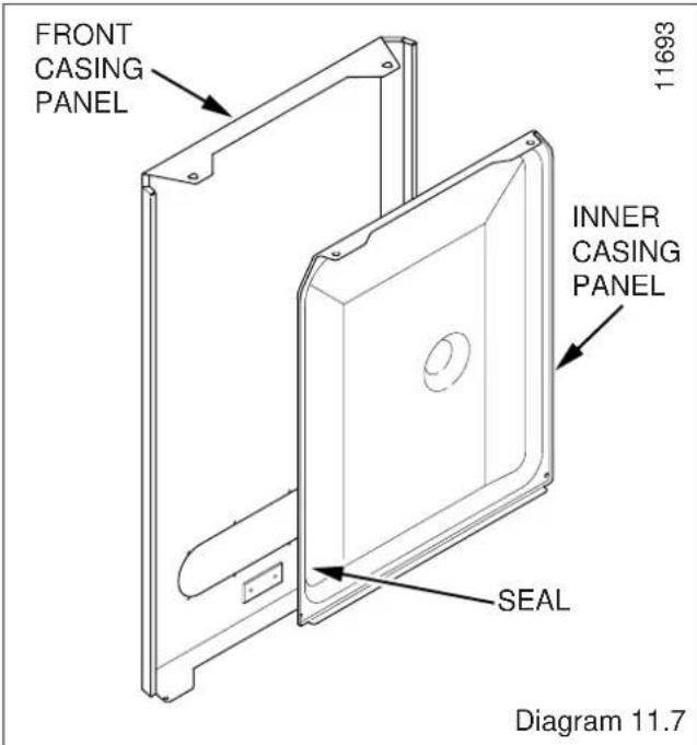
All routine servicing requirements can be achieved by the removal of the front panel, inner panel and chassis front only. Remove the two screws on the underside of the front panel and lift off. Undo the two screws on the front of inner panel and lift off, see diagram 11.7.
To remove chassis front, refer to section 11.3.
Unless stated otherwise any part removed during servicing should be replaced in the reverse order to removal.
Servicing should always include the removal of any debris from the condensate pipe and siphon.
After completing any servicing of gas carrying components, ALWAYS test for gas soundness and carry out a functional test of the controls.
11 Servicing
11.2 Spark Electrode
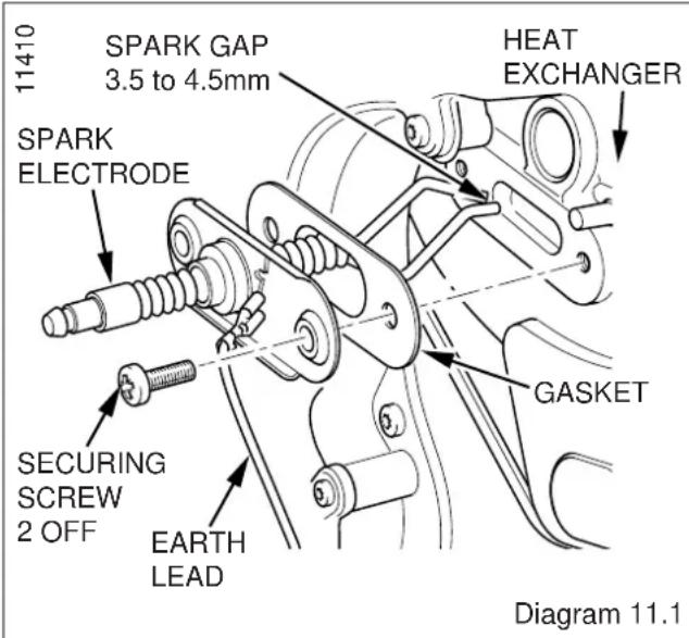
Disconnect the ignition lead and earth lead from the ignitor unit and two securing screws at the spark electrode. Withdraw the spark electrode carefully from the combustion chamber, see diagram 11.1.
Inspect the tips for damage.
Clean away any debris and check the spark gap is 3.5 -4.5 mm.
Check the electrode gasket for signs of damage and replace if necessary.

11.3 Burner
Refer to diagrams, 11.2, 11.3, 11.4 and 11.5.
Isolate the gas supply at the gas service cock.
Disconnect the gas supply at the gas service cock.
NOTE: DO NOT DISCONNECT AT THE GAS VALVE.
Remove the two gas pipe bracket securing screws from underside of inner case, see diagram 11.2.
Drop down the control panel into the service position.
Remove the four screws from the chassis front, see diagram 11.3.


11 Servicing
Remove the chassis front by pulling it out at the top from its retaining slots.
NOTE: When replacing chassis front panel ensure the bottom fits behind lip.
Disconnect the gas control valve plug at the gas control valve, see diagram 11.4.
Disconnect the electrical leads from the fan.
Remove the five combustion chamber front securing nuts, see diagram 11.5.
Gently remove the fan, gas control valve and burner assembly from the combustion chamber complete with the gas pipe bracket and seal.
Clean the burner with a soft brush taking great care not to damage the front insulation. DO NOT use wire or sharp instruments to clean the holes of the burner.
Inspect the burner for any signs of damage.
Removal of the burner is not necessary during a normal service.
NOTE: IF THE BURNER HAS TO BE REMOVED IT WILL REQUIRE A NEW GASKET WHEN REFITTED.
When replacing the assembly ensure the sealing grommet is correctly fitted.
11.4. Combustion Chamber and Heat Exchanger.
Refer to diagram 13.2.
Remove loose debris from combustion chamber using a soft brush and vacuum cleaner. Carefully flush by spraying water any remaining debris through the condensate trap (Ensure the water is kept away from electrical components).
11.5 Condensate Drain
Refer to diagram 11.6.
Remove DC fan supply, refer to section 13.5.
Remove the clips securing the flexible tubes to the siphon adaptor by twisting the clips slightly to disengage the clip jaws from each other.
Remove black flexible tubes from siphon adaptor.
Lift off the siphon adaptor.
Remove the drain connection downstream of the condense trap.
Remove the two condense trap securing screws. Lift up and carefully remove the condense trap taking care not to spill any water which may be left in the unit. As the unit is lifted remove the flexible pipe on the outlet.
Remove the cap at the base of the condense trap.
Remove any solids found.
Remove the float to clean it.
Flush water through the trap to remove any remaining solids.
Check for any debris in the outlet pipe of the condensate drain and clean as necessary.
Reassemble and refit the condense trap.
When refitting the cap ensure that a watertight seal is achieved, but do not use excessive force.
Remove the siphon adaptor from the silicone tubes, using a suitable container, flush the heat exchanger until the water appears clear in the container.

11.6 Inner Casing Panel Seal Check.
Refer to diagram 11.7.
Check the condition of the seal, replace as required.
To replace remove the old seal, thoroughly clean the casing surfaces. Fit the new seal, it is supplied to the correct length.
11.7 Combustion Check
Once the appliance has been reassembled (apart from the front and inner casing panels) connect a CO2 combustion analyser to the test point on the flueadaptor, see diagram 11.4.
Turn on the gas service cock, see diagram 11.2.
With the power off and the appliance cold, unclip the controls fascia and hinge it down to reveal the potentiometers on the rear of the User interface, see diagram 11.8. Take care not to allow the fascia to drop down and damage the wiring.
Turn on the electrical supply.
Ensure external controls are calling for heat. The boiler should fire automatically.
Allow the boiler to fire for a minimum of 60 seconds and then, using an electrical screwdriver, rotate the 'service' potentiometer fully clockwise, see diagram 11.8. This will allow the digital display to indicate the 'flashing' fan speed on the appliance fascia.
In the fully clockwise position the display should be indicating the maximum fan speed of the appliance, (54). Check the CO2 value, which should be 8.8% ± 0.2%.
Note that with the inner case front panel fitted the combustion readings will increase slightly to 9.0% ± 0.3%.
If adjustment proves necessary then proceed as follows.
Any adjustment to the gas valve should only be carried out by a qualified person.
Refer to diagram 10.2.
11 Servicing

Adjust the maximum rate CO2 with the throttle to 8.8%. (Rotate anti-clockwise to increase).
Rotate the 'service' potentiometer fully anti-clockwise. Hold it in this position for about 5 seconds before rotating the service potentiometer clockwise to the mid-point or 3 o'clock position. The fan should reduce to 1200 rpm which will flash '12' on the LCD display.
Check the CO 2 value, which should be 8.8% ± 0.2%.
If adjustment proves necessary then proceed as follows.
Adjustment of the CO2 at minimum rate is very coarse so carefully adjust the CO2 with the offset adjustment to 8.8%, see diagram 10.2.
Rotate the 'service' potentiometer fully clockwise, see diagram 11.8, and recheck the maximum rate combustion, which should be 8.8% ± 0.2% .
After checking combustion rotate the 'service' potentiometer fully anti-clockwise so that the display indicates the water temperature.
Replace the cap on the sampling point and refit the control cover rear panel.

12 Fault Finding

Diagram 12.1
12 Fault Finding
Before trying to operate the boiler make sure that :
- All gas supply cocks are open and that the gas supply has been purged of air.
- There is a permanent mains supply to the boiler.
• There is a heating demand from the external controls.
WARNING. Always isolate the boiler from the electrical supply before carrying out any electrical replacement work.
Always check for gas soundness after any service work.
Should there be any doubt about the voltage supply to any of the components, it is possible to carry out a simple electrical test to ensure all is operational in that area.
To carry out the electrical test, gain access to the main Printed Circuit Board (PCB), as follows:
Hinge down the control box.
Remove Torx screws and unhook the rear panel.
For layout of PCB, see diagram 12.1.
![graph TD A["Is there temperature indicated on LCD?"] -->|YES| B["Ensure external controls are calling for demand. Wait 60 seconds."] A -->|NO| C["Does F9 flash?"] B -->|YES| D["Negative differential<br>• Is pump direction correct?<br>• Are flow return thermistors fitted correctly?"] C -->|YES| E["Do…](/content/2026/07/1507405/images/6359003567246677f0a34e308ec3672e252d94209ef7150a601cec8aafd2a70c.jpg)
13 Replacement of Parts
13.1 General
Replacement of parts must be carried out by a competent person.
Before replacing any parts the boiler must be isolated from the mains electric supply and the gas must be turned off at the service cock on the boiler, see diagram 11.2.
Unless stated otherwise parts are replaced in the reverse order to removal.
After replacing any parts always test for gas soundness and if necessary carry out functional test of the controls.
For replacement of parts the front casing panel the inner casing panel and chassis front panel of the boiler will need to be removed. To remove undo the two screws on the underside of the front casing. Undo the two screws on the front of the inner front panel and lift off. Remove the four screws from the chassis front and remove it by pulling it out at the top from its retaining slots, see diagrams 11.7 and 11.3.
Note: When replacing chassis front panel ensure the bottom fits behind the lip.
The side panels can be hinged sideways to aid replacement of parts.
Undo and remove the three screws securing each side panel to the boiler, two at the front and one at the top.
13.2 Spark Electrode
For access, refer to section 13.1.
Remove the spark plug lead, earth lead and two securing screws. Withdraw the spark electrode carefully from the combustion chamber, see diagram 11.1.
13.3 Igniter Unit
For access, refer to section 13.1.
Remove ignition lead and electrical connections, see diagram 11.4.
Remove igniter unit by removing two securing screws.
13.4 Ignition Lead
For access, refer to section 13.1.
Refer to diagram 11.4.
Pull the spark plug style connector off the spark electrode and the spade connector connected to the igniter unit.
13.5 DC Fan Supply
For access, refer to section 13.1.
Refer to diagram 11.4.
Drop down control panel to the service position, see diagram 11.3.
Unplug white plastic plug from DC fan supply.
Undo the three screws securing PCB rear cover and lift off.
Unplug DC fan supply lead from main PCB, see diagram 13.1.
Release cable grip located on boiler case.
Remove DC fan supply cable from retaining clip located to the right of cable grip.
Undo the two screws securing DC fan supply.
Hinge R/H side panel, refer to relevant part of section 13.1.
Remove DC fan supply with lead.
13.6 Gas Control Valve
For access, refer to section 13.1.
Remove the electrical plug from the gas control valve, see diagram 10.2.
Refer to section 11.3 for removal of the fan, gas valve and burner assembly.
Before removing the gas valve note its position on the fan.
Remove the three securing screws, which fix the gas valve, plastic swirl plate to the venturi on the fan.
Remove the gas valve.
Remove the gas supply pipe from the gas control valve.

Diagram 13.1
13 Replacement of Parts
When refitting the gas valve take care as it can be fitted more than one way.
After assembly test for gas soundness and purge in accordance with the current issue of BS6891 or in IE, the current edition of I.S.813 "Domestic Gas Installations".
13.7 Fan
For access, refer to section 13.1.
Remove electrical plug.
Refer to section 11.3 for removal of the fan, gas valve and burner assembly.
Remove the gas control valve as described in the relevant parts of section 13.6.
Remove the venturi plate secured with three screws and remove the two screws securing the fan to the gas manifold, see diagram 13.2.
Check the gasket and replace if necessary.
NOTE : The Eden Vb fan is secured through an extension piece with two securing screws, check and replace any seals or gaskets if necessary.
13.8 Burner
For access, refer to section 13.1.
Refer to section 11.3 for removal of the fan, gas valve and burner assembly.
Remove the four screws that secure the burner.
NOTE: THE BURNER WILL REQUIRE A NEW GASKET WHEN REFITTED.
13.9 Front Insulation
For access, refer to section 13.1.
Refer to section 11.3 for removal of the fan, gas valve and burner assembly.
Remove burner as per section 13.8.
Remove spark electrode, see section 13.2.
NOTE: THE BURNER WILL REQUIRE A NEW GASKET WHEN REFITTED.
13.10 Rear Insulation
For access, refer to section 13.1.
Refer to section 11.3 for removal of the fan, gas valve and burner assembly.
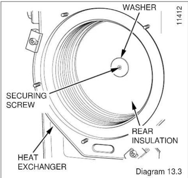
Remove securing screw and washer in the centre of the insulation and withdraw insulation, see diagram 13.3.
13.11 Viewing Window
For access, refer to section 13.1.
Refer to diagram 13.4.
Remove circlip.
Remove steel washer.
Remove glass.
Remove fibre washer.
Replace in reverse order.


13 Replacement of Parts
13.12 Heat Exchanger
For access, refer to section 13.1.
Refer to section 11.3 for removal of the fan, gas valve and burner assembly.
Drain the boiler heating circuit, see diagram 10.1.
Remove the clip securing the clear condense pipe to heat exchanger.
Pull to remove the clear condense pipe out of the bottom of the heat exchanger.
Undo the two nuts of the flow and return pipes from the heat exchanger, see diagram 13.5.
Move the pipes away from the heat exchanger.
Loosen the three heat exchanger securing screws and clamps (two at the top and one at the bottom) to remove the heat exchanger, see diagram 13.5.
CAUTION: There will be water in the heat exchanger.
Remove clear condense pipe connector from bottom of heat exchanger.
13.13 Flue Hood
For access, refer to section 13.1.
Remove heat exchanger as per section 13.12.
Remove the two securing screws and pull the hood down and away from the flue hood bracket and flue elbow, see diagram 13.6.
13.14 Heating Flow Thermistor
For access, refer to section 13.1.
Refer to diagram 13.7.
Remove the electrical connections from the thermistor.
Remove the retaining clip from the flow pipe.
Remove the thermistor from the retaining clip.
Note that the polarity of the wiring to thermistors is unimportant.
13.15 Heating Return Thermistor
For access, refer to section 13.1.
Refer to diagram 13.7.
Remove the electrical connections from the thermistor.
Remove the retaining clip from the flow pipe.
Remove the thermistor from the retaining clip.
Note that the polarity of the wiring to thermistor is unimportant.
13.16 Overheat Thermostat
For access, refer to section 13.1.
Refer to diagram 13.7.
Remove the electrical connections from the overheat thermostat.
Remove the retaining clip from the flow pipe.
Remove the overheat stat from the retaining clip.
NOTE. When fitting new thermostat, please ensure that it is located correctly onto the flat area of the pipe and the retaining clip is secure.
13.17 Condensate Drain
Refer to section 11.5.


13 Replacement of Parts
13.18 Inner Casing Sealing Panel
Refer to section 11.6.
13.19 Access to Switches, User Interface and 230v controls Interface
For access, refer to section 13.1.
Release the front of the fascia by carefully prising up the two retaining latches, see diagram 11.8.
Do not allow the front of the fascia to swing down and be loosely held by the electrical connections to the mains reset switch and user interface. Either remove the connections or support the fascia.
13.20 Mains/Reset Switch
Refer to section 13.19 for access.
Remove the switch retaining screw.
Remove switch from housing, see diagram 13.8.
Remove electrical leads.
13.21 Mains/Reset Knob
Refer to section 13.19 for access.
Remove actuator by springing back retaining clips.
Spring back knob retaining clips and push knob out from the back, see diagram 13.8.
13.22 User Interface/Display Unit PCB
Refer to section 13.19 for access and diagram 13.9.
Remove electrical plug.
Remove the three securing screws.
Withdraw the board.
When replacing the board refer to instructions supplied with replacement PCB on setting it up.
13.23 Control Box PCB
For access, refer to section 13.1
Hinge down the control box, see diagram 13.10.
Remove TORX screws and unhook the rear panel.
Remove the electrical connections to the PCB.
Prise back the two PCB retaining clips and withdraw the PCB.
When refitting the rear panel ensure the leads are not trapped, see diagram 13.1.
13.24 Control Box
For access refer to section 13.23.
Remove relevant plugs and connectors, refer to wiring diagram 12.1.
Withdraw grommets and leads so they are hanging loose.
Unthread the retaining strap and remove the control box by drawing it outwards away from its retaining slots, see diagram 13.10.


13 Replacement of Parts
13.25 Fuses
PCB - Control Box
For access, refer to section 13.23.
The fuse is located at bottom right hand side of the PCB, see diagram 13.1.
DC Fan Supply
For access, refer to section 13.1.
Refer to diagram 13.11 and wiring diagram 12.1.
Undo the two screws securing the front cover of the DC Fan Supply and remove.
The fuse is located near the centre of the PCB.
13.26 230V Controls Interface
For access, refer to section 13.19.
Disconnect the electrical connection from the 230V controls board and the electrical connection from the Control box PCB, see diagram 13.12.
Remove the 230V controls interface retaining screw.
Remove the 230V controls interface board.


14 Spare Parts
14 Spare Parts
When ordering spare parts, contact Halstead Boilers using the telephone number on the front cover of this booklet.
Please quote the name of the appliance and serial number, to be found on the data label, see diagram 1.2.
If ordering from British Gas also quote the G.C. number of the part.
| Key No. Part No. Description GC No | |||
| 1 801645 Fan assembly *****2 801637 Spark electrode *****3 801655 Igniter unit *****4 801649 Gas control valve *****5 801722 Heating flow & return thermistor (2) *****6 801724 Overheat stat *****7 801719 Control box P.C.B. *****8 801721 DC Fan supply *****9 801809 Mains/Reset Switch *****10 801734 User interface/Display Unit PCB 11 801702 Burner 12 801923 230V Controls Interface | |||

Because of our constant endeavour for improvement, details may vary slightly from those shown in these instructions.



- INSTRUCTIONS FOR USE
- INSTALLATION AND SERVICING
- EDEN VB
- HIGH EFFICIENCY
- CONDENSING BOILER
- IMPORTANT INFORMATION
- GENERAL
- GAS CATEGORY
- GAS SAFETY (INSTALLATION AND USE) REGULATIONS
- GAS TESTING AND CERTIFICATION
- CE MARK
- CONTROL OF SUBSTANCES HAZARDOUS TO HEALTH
- INSULATION PADS
- SPARE PARTS
- MANUAL HANDLING GUIDANCE
- WARNINGS
- GAS LEAK OR FAULT
- CLEARANCES
- SHEET METAL PARTS
- SEALED COMPONENTS
- ELECTRICAL SUPPLY FAILURE
- PROTECTION AGAINST FREEZING
- BOILERS INSTALLED IN A COMPARTMENT OR CUPBOARD
- BOILER CASING
- CONDENSATE DRAIN
- PLUMING FROM FLUE TERMINAL
- CLEANING
- MAINTENANCE AND SERVICING
- REPLACEMENT PARTS
- OPERATING THE BOILER
- TO OPERATE THE BOILER
- SEALED WATER SYSTEMS
- ALL SYSTEMS
- USER CONTROLS
- TO TURN THE BOILER OFF
- GENERAL INFORMATION
- IMPORTANT NOTICE
- STATUTORY REQUIREMENTS
- BSI CERTIFICATION
- GAS SUPPLY
- TECHNICAL DATA
- ELECTRICAL SUPPLY
- HEATING SYSTEM CONTROLS
- WATER SYSTEM
- DRAINING TAP
- SAFETY VALVE
- PUMP
- FLOW RATE
- BYPASS
- WATER TREATMENT
- OPEN (VENTED) WATER SYSTEM
- DOMESTIC HOT WATER CYLINDER
- DOMESTIC HOT WATER SYSTEM - UNVENTED
- EXPANSION VESSEL
- PRESSURE GAUGE
- WATER MAKEUP
- FILLING A SEALED WATER SYSTEM
- BOILER LOCATION AND VENTILATION
- BOILER LOCATION
- TIMBER FRAME BUILDINGS
- ROOM VENTILATION
- COMPARTMENT VENTILATION
- FLUE LOCATION AND VENTILATION
- FLUE POSITION AND LENGTH
- INTERNAL FLUE INSTALLATION
- FLUE OPTIONS
- HORIZONTAL FLUES
- VERTICAL FLUES
- TERMINAL POSITION
- TERMINAL GUARD
- INSTALLATION PREPARATION
- UNPACKING OF BOILER
- WALL TEMPLATE
- FLUE HOLE CUTTING
- BOILER FIXING
- HANGING BRACKET FIXING
- GAS, WATER AND CONDENSATE CONNECTIONS
- GAS CONNECTION
- WATER CONNECTIONS
- CONDENSATE DRAIN CONNECTION
- FLUE PREPARATION AND INSTALLATION
- FLUE LENGTH
- EXTENSION PIPES
- FLUE ASSEMBLY
- FLUE ATTACHMENT TO BOILER
- ELECTRICAL CONNECTIONS
- WARNING. THIS BOILER MUST BE EARTHED
- EXTERNAL CONTROLS (MAINS VOLTAGE)
- ELECTRICAL CONNECTIONS - TESTING
- PUMP CONNECTION
- COMMISSIONING
- PRELIMINARIES - ALL SYSTEMS
- SEALED SYSTEMS
- PREPARATION FOR LIGHTING
- INITIAL LIGHTING
- TESTING - GAS
- TESTING - HEATING SYSTEM
- USER CONTROLS AND OPTIONS
- TEMPERATURE DISPLAY
- PUMP EXERCISE PROGRAM
- FROST PROTECTION
- INSTRUCT THE USER
- SERVICING
- SPARK ELECTRODE
- BURNER
- COMBUSTION CHAMBER AND HEAT EXCHANGER
- INNER CASING PANEL SEAL CHECK
- COMBUSTION CHECK
- FAULT FINDING
- REPLACEMENT OF PARTS
- IGNITER UNIT
- IGNITION LEAD
- DC FAN SUPPLY
- GAS CONTROL VALVE
- FAN
- FRONT INSULATION
- REAR INSULATION
- VIEWING WINDOW
- HEAT EXCHANGER
- FLUE HOOD
- HEATING FLOW THERMISTOR
- HEATING RETURN THERMISTOR
- OVERHEAT THERMOSTAT
- INNER CASING SEALING PANEL
- ACCESS TO SWITCHES, USER INTERFACE AND 230V CONTROLS INTERFACE
- MAINS/RESET SWITCH
- MAINS/RESET KNOB
- USER INTERFACE/DISPLAY UNIT PCB
- CONTROL BOX PCB
- CONTROL BOX
- FUSES
- PCB - CONTROL BOX
- V CONTROLS INTERFACE
Brand : Halstead
Model : Eden Vb
Category : Central heating boiler