iHeat 25c - Central heating boiler Halstead - Free user manual and instructions
Find the device manual for free iHeat 25c Halstead in PDF.

| Product Type | Central heating boiler (combi) |
| Brand | Halstead |
| Model | iHeat 25c |
| Fuel Type | Natural gas |
| Output Power (heating) | 25 kW |
| Output Power (DHW) | 25 kW |
| Flow Rate (DHW) | Approx. 10.3 L/min at 35°C rise |
| Dimensions (H x W x D) | 700 x 400 x 300 mm |
| Weight | 32 kg |
| Power Supply | 230 V / 50 Hz |
| Electrical Rating | 150 W |
| IP Rating | IPX4D |
| Central Heating System | Sealed system; compatible with radiators and underfloor |
| DHW System | Instantaneous domestic hot water |
| Efficiency Rating | SEDBUK Band A (approx. 90% ERP) |
| Flue Type | Room sealed (balanced flue) |
| Controls | Front panel with thermostat and pressure gauge |
| Maintenance | Annual service recommended; access to main components front |
| Safety Features | Flame failure device, overheat thermostat, frost protection |
| Spare Parts | Available from Halstead distributors; fan, pump, PCB, heat exchanger |
| Warranty | Typically 2 years (extendable) |
| INOX Heat Exchanger | Stainless steel primary heat exchanger |
Frequently Asked Questions - iHeat 25c Halstead
User questions about iHeat 25c Halstead
0 question about this device. Answer the ones you know or ask your own.
Ask a new question about this device
Download the instructions for your Central heating boiler in PDF format for free! Find your manual iHeat 25c - Halstead and take your electronic device back in hand. On this page are published all the documents necessary for the use of your device. iHeat 25c by Halstead.
USER MANUAL iHeat 25c Halstead
iHeat 25c iHeat 30c iHeat 35c
Combination Condensing Boilers
natural_image
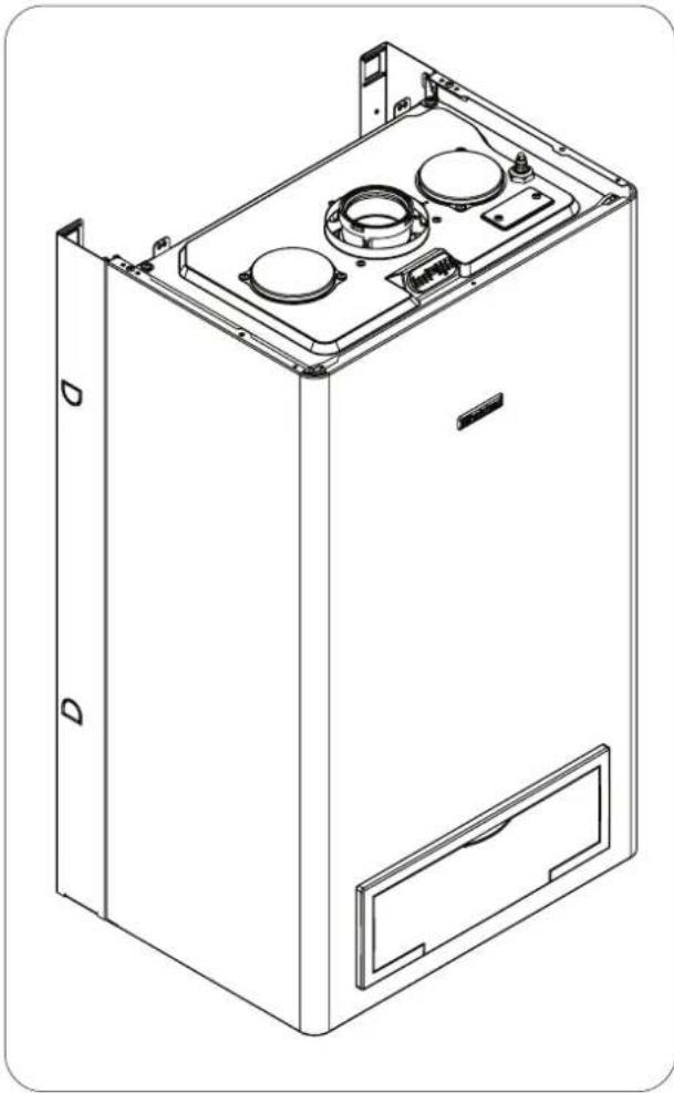
Technical line drawing of a mechanical device casing with mounting holes and internal components (no text or symbols)User Instructions
G.C. NUMBER
iHeat 25c N° 47-260-16
These instructions should be left with the user
| IntroductionIntroduction | PagePage |
| Dear customer 2 | |
| Do's and don't's 2 |
| Things you should know Things you should have Pergaw | |
| 1.1 Gas appliances 3 | |
| 1.2 Electrical supply | 3 |
| 1.3 Guarantee registration card | 3 |
| 1.4 Appliance log book (UK only) | 3 |
| 1.5 How does it work? | 3 |
| 1.6 Dimensions | 3 |
| 1.7 Clearances required | 3 |
| 1.8 Frost protection system | 3 |
| 1.9 Status indicators | 3 |
| 1.10 Digital display | 4 |
| Getting started | PagePage |
| 2.1 Before switching on | 5 |
| 2.2 Appliance controls | 5 |
| 2.3 Lighting the boiler | 5 |
| 2.4 Adjusting the CH temperature | 5 |
| 2.5 Adjusting the DHW temperature | 5 |
| How to... | PagePage |
| 3.1 Top-up the system | 6 |
| 3.2 Reset the appliance | 6 |
| 3.3 Shut down the system for short periods | 6 |
| 3.4 Shut down the system for long periods | 6 |
| 3.5 Care for the appliance | 6 |
| What if... | Page |
| 4.1 I suspect a gas leak | 7 |
| 4.2 I have to frequently to top-up the system | 7 |
| 4.3 The fault light is on | 7 |
| 4.4 The appliance is due its annual service | 7 |
| 4.5 I need to call an engineer | 7 |
| 4.6 I need to extend the warranty | 7 |
| Setting | PagePage |
| 5.1 Mechanical clock | 7 |
Introduction
Dear Customer
Your boiler has been designed to meet and exceed the very latest standards in gas central heating technology, and if cared for, will give years of reliable use and efficiency.
Please therefore take some time to read these instructions carefully.
Do's and Don't's
- Do ensure that the system pressure is periodically checked
- Do ensure that you know how to isolate the appliance in an emergency
- Do ensure that you are familiar with the appliance controls
- Do ensure that your installer has completed the appliance log book section
- Do not data recept to remove the appliance casing or gain internal access
- Do not change clothes etc. over the appliance
- Do not forget to have the appliance serviced annually. This booklet is an integral part of the appliance. It is therefore necessary to ensure that the booklet is handed to the person responsible for the property in which the appliance is located/installed. A replacement copy can be obtained from the customer services.
1.0 Things you should know
1.11 Gas appliancesGas appliances
Gas Safety (Installations and Use) Regulations (UK). In the interests of your safety and that of others it is a legal requirement that all gas appliances are installed and correctly maintained by a competent person and in accordance with the latest regulations.
1.21 Electrical supply Electrical supply
Please ensure that this appliance has been properly connected to the electrical supply by means of a double pole isolator or un-switched socket, and that the correct size of fuse (3 AMP) has been fitted. Warning: this appliance must be earthed!
1.31 Guarantee registration cardGuarantee registration ca
Please take the time to fill out your guarantee registration card. The completed warranty card should be posted within 30 days of installation.
1.4 Appliance Benchmark LogbookAppliance Benchmark I
See rear of booklet for full terms and conditions of your iHe® lifetime guarantee.
A logbook section can be found at the rear of the appliance installation booklet. This important document must be completed during the installation/commissioning of your boiler. All CORGI registered installers carry a CORGI ID card, and have a registration number. These details should be recorded in the Benchmark logbook section within the installation booklet. You can check your installers details by calling CORGI direct on 01256 372300. Failure to install and commission the appliance in accordance with the manufacturers instructions may invalidate the warranty. This does not affect your statutory rights.
1.51 How does it work? How does it work?
Your iHeHeboiler supplies heated water to your radiators and hot water to your hot water taps.
The central heating is controlled via a time clock and any thermostats that your installer may have fitted. The boiler will light when it receives a request from the time clock via any thermostat that may be installed, or whenever a hot water outlet (tap) is opened.
Your iHeiHeboiler lights electronically and does not have a pilot light.
In the unlikely event of a fault developing with your boiler, the supply of gas to the burner will be terminated automatically.
1.81 Frost protection systemFrost protection system
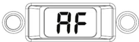
The iHeat is equipped with a built-in frost protection system, this enables the boiler to over-ride the time controls – even if switched off – and operate the burner and/or pump, should the temperature drop below 6°C for the main and below 4°C for the DHW line. In particular the burner will be in ON status until the main temperature reaches 35°C for CH appliance and 55°C for DHW appliance.
Please note that the frost protection system is designed to protect the appliance only, should frost protection be required for the heating system, additional controls may be required.
When the frost protection system has been activated, 'AF' is displayed on the appliance LED display (see picture).
NOTE
The frost protection system is reliant on the appliance having a permanent electrical supply, and being in a non-fault condition.
1.91 Appliance status indicators
Your boiler is equipped with 2 status LED indicators, the Green LED indicates that the flame is present, whilst the Red LED indicates the appliance has detected a fault.
1.61 Dimensions
| iHeat25c | |
| HEIGHT | 780mm |
| WIDTH | 400mm |
| DEPTH | 358mm |
| iHeat30c - iHeat35c | |
| HEIGHT | 780mm |
| WIDTH | 450mm |
| DEPTH | 358mm |
1.71 Clearances required
| ABOVE | 150 mm |
| BELOW | 150 mm |
| LEFT SIDE | 50 mm |
| RIGHT SIDE | 12mm |
| FRONT | 600 mm |
1.10 Digital display Digital display
The 2-digit digital display will normally show the current working (outlet) temperature of the boiler, however in certain circumstances a fault code or specific characters will be displayed to indicate that the appliance is performing a specific function.
- Pressure gauge
- Hot water temperature selector
- Green LED indicator
- 2-digit display
- Red LED indicator
- Heating temperature selector
- Clock (if fitted)
- Mode selector switch
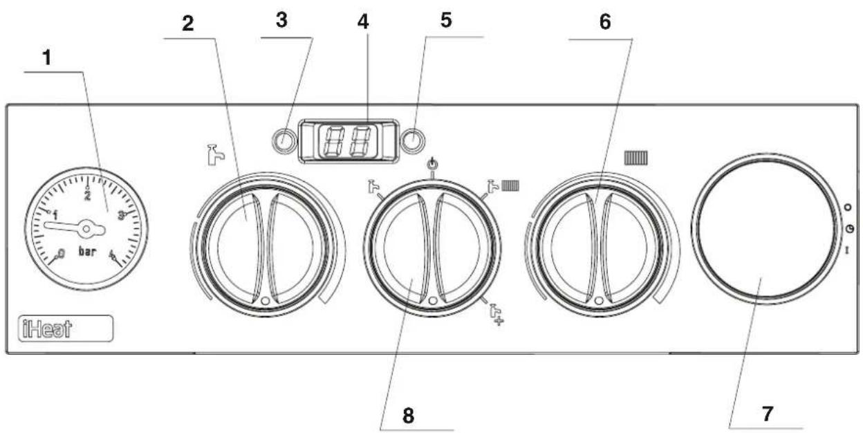
fig. 1fig. 1
2.02.Getting startedGetting started
2.12 Before switching on Before switching on
Before switching the appliance on please familiarise yourself with:
●how to isolate the appliance from the gas, water, and electricity supplies;
- how to check and top-up – if necessary – the system water pressure;
●the time clock or programmer;
●any external thermostats and their functions;
●the appliance controls.
2.22 Appliance controls (see fig. 1)Appliance cont
The appliance controls are situated on the lower front of the appliance. The appliance controls include:
●pressure gauge;
●appliance mode selector;
●temperature selector;
●2-digit LED display;
- burner ON mode (green);
- fault indicator (red);
- optional - integral time clock/programmer (if fitted).
The pressure gauge shows the current pressure of your heating system, the gauge should be set between 1 and 1.5 BAR. When the appliance is operating the gauge may rise or fall slightly, this is quite normal. The minimum permissible level for the safe and efficient operation of the appliance is 0.5 BAR. Should the pressure fall below 0.5 BAR, the boiler may lockout.
The appliance mode selector is used to switch the boiler to the various operating modes:
- OFF/RESET "

●DHW MODE

-CH MODE "

-CH with
PREHEATING MODE

NOTE
The appliance frost protection is active in all of the above modes.
The temperature selectors can be used to vary the temperature of the water that circulates around your radiators and the water that flows from your hot water taps. The temperature range is adjustable between 40°C and 80°C for the central heating, and between 35°C and 60°C for the hot water. Moreover if floor heating mode is selected (by using the relative jumper), the temperature range for CH mode can be modified between 20°C and 45°C.
The 2-digit LED display normally shows the operating temperature of the appliance, however it can also display additional characters or flashing numbers to signify specific operating modes or fault codes.
When the status indicator (Green) is lit it indicates that the flame is present and the burner is ON.
When the fault indicator (Red) is lit it indicates that the appliance has identified a possible fault and performed a safety lockout.
The integral time clock (when fitted) can be used to switch the heating on and off at pre-determined intervals.
The integral time clock or programmer (when fitted) can be used to switch the heating and/or hot water on and off at pre-determined intervals.
2.3 Lighting the boiler
Ensure the gas and electrical supply to the boiler are turned on.
Turn the mode selector switch to the ON position. When there is a request for heating or hot water via the time clock or programmer, the boiler will begin an ignition sequence. When the appliance reaches the set temperature, the burner will go off for a minimum period of approximately 3 minutes.
When the programmer/time clock or external thermostats heating request has been satisfied, the appliance will switch off automatically.
2.4 Adjusting the heating temperature
Rotate the temperature selector – clockwise to increase, counter-clockwise to decrease – to the desired temperature setting. The temperature can be set from a minimum of 40^ C to a maximum of 80^ C (if standard CH mode is selected).
2.5 Adjusting the hot water temperature
Rotate the temperature selector – clockwise to increase, counter-clockwise to decrease – to the desired temperature setting. The temperature can be set from a minimum of 35^ C to a maximum of 60^ C. If the temperature at the outlet is still not sufficiently hot enough, it may be necessary to reduce the flow of water at the hot water outlet (tap).
NOTE
If the appliance fails to ignite during the ignition sequence, it will enter a lockout condition. Should this occur, please allow a period of at least two minutes before re-setting the appliance.
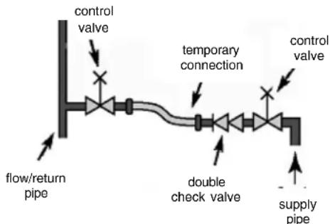
flowchart
graph LR
    A["flow/return pipe"] --> B["control valve"]
    B --> C["temporary connection"]
    C --> D["control valve"]
    D --> E["supply pipe"]
    F["double check valve"] --> C
    G["control valve"] --> C
fig. 2fig. 2
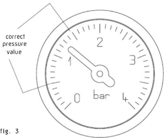
fig. 3fig. 3
APPLIANCELIANUET CODESODES
CODECADETION REQUIRED ACTION REQUIRED
AL10 Reset appliance. Call engineer if fault re-occurs
AL20 Reset appliance. Call engineer if fault re-occurs
AL21 Reset appliance. Call engineer if fault re-occurs
AL26 Reset appliance. Call engineer if fault re-occurs
AL28 Reset appliance. Call engineer if fault re-occurs
AL34 Reset appliance. Call engineer if fault re-occurs
AL40 Check system pressure and refill if necessary. Reset appliance. Call engineer if fault re-occurs
AL41 Check system pressure and refill if necessary. Call engineer if fault re-occurs
AL52 Call engineer
AL55 Call engineer
AL60 Reset appliance. Call engineer if fault re-occurs
AL71 Call engineer if fault re-occurs
AL73 Call engineer if fault re-occurs
AL74 Reset appliance. Call engineer if fault re-occurs
AL79 Reset appliance. Call engineer if fault re-occurs
3.0 How to ...
3.13 How to top-up the system pressure (fig.How to top 2 & 3)2 & 3)
The system pressure must be checked periodically to ensure the correct operation of the boiler. The needle on the gauge should be reading between 1 and 1.5 BAR when the boiler is in an off position and has cooled to room temperature. If the pressure requires 'topping-up' use the following instructions as a guide.
- Locate the filling valve connections (usually beneath the boiler, see fig. 2).
- Attach the filling loop to both connections.
- Open the filling valve slowly until you hear water entering the system.
- Close the filling valve when the pressure gauge (on the boiler) reads between 1 and 1.5 BAR.
- Remove the filling loop from the connections.
3.23 How to reset the applianceHow to reset the applian
When the red fault LED is illuminated, the appliance will require to be reset manually. Before resetting the boiler, check what action is required to be taken, using the information on the fault code table below. Allow a period of two minutes to elapse before rotate the mode selector knob across the OFF/RESET position.
IMPORTANT
If the appliance requires to be reset frequently, it may be indicative of a fault, please contact your installer or the Customer Services for further advice.
3.35 How to shut down the system for short periods
The system and boiler can be shut down for short periods by simply turning the time clock to the off position. It is also advisable to turn off the main water supply to the house.
3.43 How to shut down the system for long periods
If the house is to be left unoccupied for any length of time – especially during the winter – the system should be thoroughly drained of all water. The gas, water, and electricity supply to the house should also be turned off. For more detailed advice contact your installer.
3.53 How to care for the appliance
To clean the outer casing use only a clean damp cloth. Do not use any scourers or abrasive cleaners.
natural_image
Technical diagram of a circular mechanical or electrical component with concentric rings and radial slots, no text or symbols present.OFF
AUTO
ON
4.04.What if
4.1 I suspect a gas leak
If you suspect a gas leak, turn off the gas supply at the gas meter, and contact your installer or local gas supplier. If you require further advice please contact your nearest Service & Technical Helpline (0844 371 1111).
4.2 I frequently "top-up" or "repressurise the system
If the system regularly requires topping-up or re-pressurising, it may be indicative of a leak. Please contact your installer and ask him to inspect the system.
4.3 The fault light is on
If the Red LED light is illuminated, it indicates that the boiler has failed to ignite or has detected a possible fault. When this happens the boiler automatically shuts down and requires to be reset manually (see 3.2).
4.44 The appliance is due its annual service
Please contact the Service & Technical Helpline (0844 371 1111) if you would prefer an authorised engineer or agent to service your appliance. Alternatively your local CORGI registered engineer may be able to service the appliance for you. If you are a tenant your landlord will arrange for servicing.
4.54 I need to call an engineer
If you think your boiler may have developed a fault, please contact your installer or the Service & Technical Helpline (0844 371 1111). Have all your details to hand including full address and postcode, relevant contact numbers and your appliance logbook.
4.64 I want to extend the warranty
You can if you wish, extend the warranty on your iHeat boiler. Simply contact our Service & Technical Helpline (0844 371 1111) for further information.
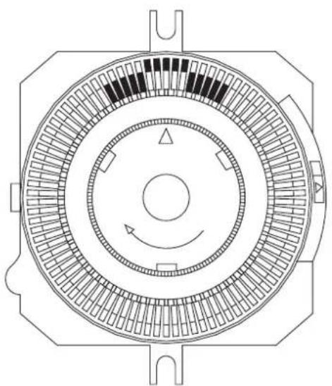
5.05 Setting the mechanical clock
5.15 Setting the mechanical clockSetting the mechanical
If your boiler has been installed with the mechanical clock, it can be used and adjusted as follows:
Setting the timeSetting the time
The time of day can be set by grasping the outer edge of the black dial and turning it in a clockwise direction until the correct time is in line with the white pointer.
Setting the "switching times" Setting the "switching times"
The "ON" periods "ON" periods sliding the black tappets, adjacent to the time periods required, to the outer edge of the dial.
The tappets that remain at the centre of the dial will be the "OFF" periods. "OFF" periods
The smallest switching time (ON or OFF) is 15 minutes.
To select "AUTO" mode move the selector switch in central position.
To select "ON" "ON"e move the selector switch in the bottom position.
To select "OFFMODE move the selector switch in the upper position.
Shalstead
GLEN DIMPLEX
WARRANTY TERMS & CONDITIONS + LIFETIME WARRANTY WARRANTY TERMS & CONDITIONS + LIFETIME WARR
- Registration must be completed within 30 days of installation. Failure to return within 30 days will invalidate your warranty. Registration if effected by returning the enclosed registration card to the commercial center of Halstead Glen Dimplex at 5 Spartan Close, Tachbrook Park, Leamington Spa, CV34 6RR. Proof of postage should be obtained.
- The Benchmark document must be completed by installer/householder at the time of installation and must be presented to our engineer at subsequent visits.
- The boiler must be serviced annually, at the householders expenses in accordance with manufacturer's instructions, and this service must be booked through Halstead Glen-Dimplex by calling 0844 371 1111.
- The service must be carried out by a Halstead approved central heating engineer. Any work carried out by a non-Halstead approved engineer will invalidate this warranty.
- Appropriate system cleaning (e.g. power flush) and the correct use of additives must be carried out at the time of installation. Failure to cleanse the system will invalidate this warranty. Evidence of cleansing should be presented to our engineer upon request.
- Based on a typical boiler lifespan, Halstead deem the life of a boiler to be 10 years from the date of installation. At the end of 10 years, the owner can choose to continue to use the boiler (un-warranted), or Halstead will offer to install a replacement at a preferential price.
- This warranty applies only to manufacturing problems with the boiler; damage caused through misuse, incorrect operation, foreign bodies in the heating system, system faults and failures are not covered.
- This warranty applies only if the boiler is installed and used in accordance with the manufacturer's instructions, in normal domestic applications.
- Providing all the above Terms and Conditions are met, this warranty covers functional parts and labour. Functional parts are detailed in the attached appendix, together with specific exclusions.
- Halstead Glen Dimplex offer the opportunity for a system audit and commissioning check within 30 days of registration. This is chargeable at the same rate as an annual service and if taken up then the first annual service will be provided free of charge. Failure to take up this offer may invalidate the full warranty which will revert to a standard 1 year warranty
- Failure to meet any of the above Terms and Conditions will invalidate this warranty.
APPENDIX APPENDIX
| Problem attributable to failure of:Problem attributed failures | |
| Main heat exchanger Premature corrosion caused by pollutants and chemicals in the gas and air | |
| Plate heat exchanger Problems attributable to scaling | |
| Fan | Problems caused by pollutants or incorrect wiring (e.g. by installer), failure caused by water spillages |
| Gas Valve | Problems caused by pollutants and chemicals in the air and gas |
| Pump | Problems attributable to dry-firing, limescale and magnetite |
| PCB | Failure attributable to incorrect wiring (e.g. by installer), failure caused by water spillages |
| Expansion vessel | Problems attributable to chemicals in the water |
| Any part of hydroblock | Problems attributable to incorrect components positioning (e.g. by installer) |
| Electrodes | Premature corrosion caused by pollutants and chemicals in the gas and air |


TECHNICAL SERVICES, TRAINING AND MARKETING
Halstead Boilers Limited, 5 Titan Business Centre, Spartan Close, Tachbrook Park, Leamington Spa,
Warwickshire CV34 6RR - Telephone: 0844 371 1111 Fax: 01926 834888
MANUFACTURING, ACCOUNTS AND SALES
Halstead Boilers Limited, 20/22 First Avenue, Bluebridge Industrial Estate, Halstead, Essex C09 2EX
Telephone: 0844 371 1111 Fax: 01787 474588
Part of the Glen Dimplex Group
Email:sales@halsteadboilers.co.uk or service@halsteadboilers.co.uk or training@halsteadboilers.co.uk
Website:www.halsteadboilers.co.uk
Halstead Boilers is continuously improving its products and may therefore change specifications without prior notice.
The statutory rights of the consumer are not affected.08/07