
StorageWorks SN6000 - Switch HP - Free user manual and instructions
Find the device manual for free StorageWorks SN6000 HP in PDF.


| Product Type | Fibre Channel Switch |
| Model | HP StorageWorks SN6000 |
| Number of Ports | 16 |
| Port Speed | 4 Gbps (auto-negotiable to 2/1 Gbps) |
| Form Factor | 1U Rack-mountable |
| Dimensions (H x W x D) | 1.72 in x 17.5 in x 15.0 in (4.37 cm x 44.45 cm x 38.1 cm) |
| Weight | Approximately 22 lbs (10.0 kg) |
| Power Supply | Dual redundant hot-swappable AC power supplies |
| Input Voltage | 100-240 VAC, 50/60 Hz |
| Power Consumption (Typical) | 120 W |
| Cooling | Internal fans with front-to-back airflow |
| Management Interfaces | Serial console (RJ-45), Ethernet (10/100/1000), USB |
| Management Protocols | SNMP, Telnet, SSH, HTTP/HTTPS, CLI |
| Operating Temperature | 32°F to 104°F (0°C to 40°C) |
| Storage Temperature | -4°F to 158°F (-20°C to 70°C) |
| Operating Humidity | 10% to 90% non-condensing |
| Certifications | FCC, CE, UL, VCCI, BSMI, ICES-003, CSA |
| Safety | IEC 60950-1, EN 60950-1, UL 60950-1 |
| Warranty | 3 years parts and labor (subject to terms) |
| Maintenance and Cleaning | Use a dry, lint-free cloth; avoid liquids; clean dust from vents regularly |
| Spare Parts and Repairability | Hot-swappable power supplies and fans; no user-serviceable internal parts; contact HP support for repairs |
| General Information | Designed for SAN connectivity; supports FICON and FC-SB-3 |
Frequently Asked Questions - StorageWorks SN6000 HP
User questions about StorageWorks SN6000 HP
0 question about this device. Answer the ones you know or ask your own.
Ask a new question about this device
Download the instructions for your Switch in PDF format for free! Find your manual StorageWorks SN6000 - HP and take your electronic device back in hand. On this page are published all the documents necessary for the use of your device. StorageWorks SN6000 by HP.
USER MANUAL StorageWorks SN6000 HP
HP StorageWorks SN6000 Fibre Channel Switch Installation and Reference Guide
Legal and notice information
© Copyright 2010 Hewlett-Packard Development Company, L.P.
© Copyright 2010. This software includes technology under a license from QLogic Corporation. All rights reserved.
The information contained herein is subject to change without notice. The only warranties for HP products and services are set forth in the express warranty statements accompanying such products and services. Nothing herein should be construed as constituting an additional warranty. HP shall not be liable for technical or editorial errors or omissions contained herein.
Java® is a registered trademark of Sun Microsystems, Inc.
Microsoft®, Windows®, and Internet Explorer® are registered trademarks of Microsoft Corporation.
Netscape Navigator® and Mozilla® are registered trademarks of Netscape Communications Corporation.
HP StorageWorks SN6000 Fibre Channel Switch Installation and Reference Guide

Contents
About this guide. 7
Intended audience 7
Related documentation 7
Document conventions and symbols 8
Rack stability 9
HP technical support 9
Customer self repair 9
Product warranties 9
Subscription service 9
HP websites 10
Documentation feedback.... 10
1 General description 11
Switch LEDs and controls 12
Input power LED (green) 12
Heartbeat LED (green) 12
System fault LED (amber).... 12
Maintenance button 13
Resetting a switch 13
Placing the switch in maintenance mode 13
Fibre Channel ports 14
Port LEDs 15
Port Logged-in LED (green) 15
Port Activity LED (green).... 15
Transceivers 15
Port types 15
Ethernet port 17
Serial port 17
Power supplies and fans 18
Switch management 19
QuickTools web applet.... 19
Simple SAN Connection Manager.... 19
Command line interface 19
Simple Network Management Protocol.... 20
Storage Management Initiative-Specification (SMI-S) 20
File transfer protocols 20
2 Planning 21
Devices 21
Device access 21
Performance.... 22
Distance 22
Bandwidth 22
Latency.... 23
Feature licenses 23
Multiple switch fabrics.... 23
Optimizing device performance.... 23
Domain ID, principal priority, and domain ID lock 24
Stacking 24
Common topologies.... 26
Transparent routing 26
Switch services....28
Security 30
User account security 30
IP security 30
Port binding 30
Connection security 30
Device security 31
Fabric management 32
3 Installation 33
Site requirements 33
Management Station and Workstation requirements 33
Switch power requirements 34
Environmental conditions 34
Installing a switch 34
Mount the switch 35
Before you begin 35
Collect the required items 36
Verify the kit contents 36
Rack the switch. 37
Install the transceivers.... 39
Configure the workstation.... 39
Configuring the workstation IP address for Ethernet connections 39
Configuring the workstation serial port 39
Apply power to the switch 40
Connect the management station or workstation to the switch 41
Configure the switch 41
Simple SAN Connection Manager switch configuration. 41
QuickTools switch configuration 42
CLI switch configuration.... 42
Cable devices to the switch.... 42
Installing firmware 43
Using QuickTools to install firmware 43
Using the CLI to install firmware. 44
One-step firmware installation 44
Custom firmware installation 45
Adding a switch to an existing fabric 45
Installing feature license keys 46
Configuring Call Home to HP Services (optional) 46
Role of the Remote Support Software Manager 46
Role of OSEM and versions required 46
Installation instructions and documentation for SIM, RSP, OSEM, and ISEE 47
RSP requirements for the CMS 47
Infrastructure requirements for implementing Call Home to HP Services 48
Configuring Call Home to HP services 48
4 Diagnostics and troubleshooting 51
Switch diagnostics 51
Input power LED is extinguished 51
System fault LED is illuminated. 52
Power-On self test diagnostics 52
Heartbeat LED blink patterns 52
Internal firmware failure blink pattern 52
Fatal POST error blink pattern 53
Configuration file system error blink pattern 53
Over-temperature blink pattern 53
Logged-in LED indications 54
E_Port isolation.... 54
Excessive port errors 55
Transceiver diagnostics 56
Power Supply Diagnostics 56
Recovering a switch using maintenance mode 57
Exiting the maintenance menu (option 0) 58
Unpacking a firmware image file in maintenance mode (option 1). 58
Resetting the network configuration in maintenance mode (option 2) 58
Resetting user accounts in maintenance mode (option 3)....58
Copying log files in maintenance mode (option 4)....58
Removing the switch configuration in maintenance mode (option 5).... 58
Remaking the file system in maintenance mode (option 6)....58
Resetting the switch in maintenance mode (option 7) 59
Updating the boot loader in maintenance mode (option 8) 59
5 Removal/Replacement 61
Transceiver Removal and Replacement 61
Power Supply Removal and Replacement.... 61
A Regulatory compliance and safety 65
Regulatory compliance 65
Federal Communications Commission notice for Class A equipment. 65
Cables. 65
Laser device 65
Laser safety warning 65
Certification and classification information.... 66
Laser product label 66
International notices and statements 66
European Union regulatory notice 67
Japanese notice....67
Korean notice 67
Taiwan notice 67
B Electrostatic discharge 69
How to prevent electrostatic discharge 69
Grounding methods 69
C Technical specifications....71
General specifications....71
Maintainability features....73
Fabric management specifications 73
Weight and physical dimensions 74
Electrical specifications 74
Environmental requirements 74
D Factory configuration defaults 75
Factory switch configuration.... 75
Factory port configuration 76
Factory port threshold alarm configuration.... 77
Factory zoning configuration 77
Factory SNMP configuration 78
Factory switch services configuration.... 78
Factory DNS host name configuration 79
Factory IP version 4 Ethernet configuration....79
Factory IP version 6 Ethernet configuration....80
Factory event logging configuration 80
Factory NTP server configuration 80
Factory timer configuration 80
Factory RADIUS configuration 81
Factory security configuration.... 81
Factory Call Home configuration 82
Glossary 83
Index 87
Figures
1 SN6000 Fibre Channel Switch 11
2 Switch LEDs and controls 12
3 Fibre Channel ports 14
4 Port LEDs 15
5 Ethernet port 17
6 Serial port and pin identification 17
7 SN6000 Power Supplies 18
8 Two-switch stack 24
9 Three-switch stack 25
10 Four-switch stack 25
11 Five-switch stack 25
12 Six-switch stack 26
13 Attaching the rails to the switch 37
14 Installing the rear mounting brackets 37
15 Installing the switch and rail assembly 37
16 Fastening the rail to the front of the rack 38
17 Fastening the rail to the rear mounting bracket 38
18 Installing the filler panel 38
19 Management station and workstation cable connections.... 41
20 Switch LEDs 51
21 Logged-in LED 54
22 SN6000 Fibre Channel Switch Power Supply LEDs 56
23 Power Supply Removal 62
24 Power Supply Installation 63
25 Class 1 laser product label 66
Tables
1 Document conventions 8
2 Fibre Channel port types 16
3 Serial port pin identification 18
4 Zoning database limits....22
5 Port-to-port latency 23
6 Management station requirements for Simple SAN Connection Manager 33
7 Workstation requirements for QuickTools 34
8 SN6000 Fibre Channel Switch rack mount kit hardware 36
9 General specifications 71
10 Maintainability features 73
11 Fabric management specifications....73
12 Switch physical dimensions....74
13 Electrical specifications....74
14 Environmental requirements 74
15 Switch configuration defaults. 75
16 Port configuration defaults 76
17 Port threshold alarm configuration defaults 77
18 Zoning configuration defaults 77
19 SNMP configuration defaults....78
20 Services configuration defaults 78
21 DNS host name configuration defaults 79
22 IP version 4 Ethernet configuration defaults....79
23 IP version 6 Ethernet configuration defaults....80
24 Event logging configuration defaults....80
25 NTP server configuration defaults....80
26 Timer configuration defaults 80
27 RADIUS configuration defaults....81
28 Security configuration defaults....81
29 Call Home service configuration defaults 82
About this guide
This guide provides information about:
- Becoming acquainted with the switch features and capabilities
- Planning a fabric including devices, device access, performance, multiple switch fabrics, switch services, fabric security, and fabric management.
• Installing and configuring an HP StorageWorks SN6000 Fibre Channel Switch
• Diagnosing and troubleshooting switch problems
Intended audience
This manual introduces users to the switch and explains its installation and service. It is intended for users who are responsible for installing and servicing network equipment.
Related documentation
In addition to this guide, see the following documents for this product:
• HP StorageWorks SN6000 Fibre Channel Switch Quick Start Installation Instructions
• HP StorageWorks 8Gb Simple SAN Connection Kit Quick Start Instructions
- HP StorageWorks 8/20q and SN6000 Fibre Channel Switch Rack Mount Kit Quick Start Installation Instructions
• HP StorageWorks SN6000 Fibre Channel Switch QuickTools Switch Management User Guide
• HP StorageWorks SN6000 Fibre Channel Switch Command Line Interface Guide
• HP StorageWorks SN6000 Fibre Channel Switch Command Line Interface Quick Reference Guide
• HP StorageWorks Simple SAN Connection Manager User Guide
• HP StorageWorks 8/20q and SN6000 Fibre Channel Switch Event Message Reference Guide
- HP StorageWorks 8/20q and SN6000 Fibre Channel Switch Simple Network Management Protocol Reference Guide
• HP StorageWorks 8/20q and SN6000 Fibre Channel Switch CIM Agent Reference Guide
For the latest product information, including firmware, documentation, and supported SAN configurations, see the following HP website: http://www.hp.com/go/SN6000
Document conventions and symbols
Table 1 Document conventions
| Convention Element | |
| Medium blue text: Figure 1 | Cross-reference links and e-mail addresses |
| Medium blue, underlined text (http://www.hp.com) | Website addresses |
| Bold font • Keys that are pressed | • Text typed into a GUI element, such as into a box• GUI elements that are clicked or selected, such as menu and list items, buttons, and check boxes |
| Italics font Text emphasis | |
| Monospace font • File and directory names | • System output• Code• Commands, their arguments, and argument values |
| Monospace, italic font • Code variables | • Command-line variables |
| Monospace, bold font Emphasis of m | monospace text, including file and directory names, system output, code, and text typed at the command line |
⚠ WARNING! Indicates that failure to follow directions could result in bodily harm or death.
△ CAUTION: Indicates that failure to follow directions could result in damage to equipment or data.
IMPORTANT: Provides clarifying information or specific instructions.
NOTE: Provides additional information.
TIP: Provides helpful hints and shortcuts.
⚠ WARNING! To reduce the risk of personal injury or damage to equipment:
- Extend leveling jacks to the floor.
- Ensure that the full weight of the rack rests on the leveling jacks.
• Install stabilizing feet on the rack.
• In multiple-rack installations, secure racks together.
- Extend only one rack component at a time. Racks may become unstable if more than one component is extended.
HP technical support
Telephone numbers for worldwide technical support are listed on the HP support website: http://www.hp.com/support/.
Collect the following information before calling:
• Technical support registration number (if applicable)
• Product serial numbers
• Product model names and numbers
• Applicable error messages
- Operating system type and revision level
• Detailed, specific questions
Customer self repair
HP customer self repair (CSR) programs allow you to repair your StorageWorks product. If a CSR part needs replacing, HP ships the part directly to you so that you can install it at your convenience. Some parts do not qualify for CSR. Your HP authorized service provider will determine whether a repair can be accomplished by CSR.
For more information about CSR, contact your local service provider. For North America, see the CSR website:
http://www.hp.com/go/selfrepair
This product has no customer replaceable components.
Product warranties
For information about HP StorageWorks product warranties, see the warranty information website: http://www.hp.com/go/storagewarranty
Subscription service
HP strongly recommends that customers sign up online using the Subscriber's choice website: http://www.hp.com/go/e-updates.
- Subscribing to this service provides you with e-mail updates on the latest product enhancements, newest versions of drivers, and firmware documentation updates as well as instant access to numerous other product resources.
• After signing up, you can quickly locate your products by selecting Business support and then Storage under Product Category.
HP websites
For other product information, see the following HP websites:
- http://www.hp.com
- http://www.hp.com/go/storage
- http://www.hp.com/support/
- http://www.docs.hp.com
Documentation feedback
HP welcomes your feedback.
To make comments and suggestions about product documentation, please send a message to storagedocs.feedback@hp.com. All submissions become the property of HP.
1 General description
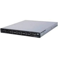
The HP StorageWorks SN6000 Fibre Channel Switch (Figure 1) is a 24 port, 8 Gb/s switch with both Ethernet and serial management interfaces. This section describes the features and capabilities of the HP StorageWorks SN6000 Fibre Channel Switch and includes information about the following features:
• Switch LEDs and controls, page 12
• Fibre Channel ports, page 14
- Ethernet port, page 17
• Power supplies and fans, page 18
- Switch management, page 19
Fabrics are managed with the Command Line Interface (CLI) and the QuickTools web applet. You can also use the HP StorageWorks Simple SAN Connection Manager, which provides basic switch management functions, such as IP address configuration, and limited control of zoning.
- For more information about the CLI, see the HP StorageWorks SN6000 Fibre Channel Switch Command Line Interface Guide.
- For information about QuickTools, see the HP StorageWorks SN6000 Fibre Channel Switch QuickTools Switch Management User Guide.
- For information about Simple SAN Connection Manager, see the HP StorageWorks Simple SAN Connection Manager User Guide.

Figure 1 SN6000 Fibre Channel Switch
Switch LEDs and controls
The switch LEDs provide information about the switch's operational status. These LEDs include the Input Power LED (green), Heartbeat LED (green), and the System Fault LED (amber) (Figure 2). For information about port LEDs, see "Port LEDs" on page 15. The Maintenance button (Figure 2) is the only switch control. It is used to reset a switch or to recover a disabled switch. To apply power to the switch, plug the power cord into the switch AC power receptacle, located on the back of the switch, and into a 100-240 VAC power source.

1 Input Power LED (green)
2 Heartbeat LED (green)
3 System Fault LED (amber)
4 Maintenance button
Figure 2 Switch LEDs and controls
Input power LED (green)
The Input Power LED indicates the voltage status at the switch logic circuitry. During normal operation, this LED illuminates to indicate that the switch logic circuitry is receiving the proper DC voltages. When the switch is in maintenance mode, this LED is extinguished.
Heartbeat LED (green)
The Heartbeat LED indicates the status of the internal switch processor and the results of the POST. Following a normal power-up, the Heartbeat LED blinks about once per second to indicate that the switch passed the POST and that the internal switch processor is running. In maintenance mode, the Heartbeat LED illuminates continuously. For more information, see "Heartbeat LED blink patterns" on page 52.
System fault LED (amber)
The System Fault LED illuminates to indicate that a fault exists in the switch firmware or hardware. Fault conditions include POST errors, over-temperature conditions, and power supply malfunctions. The Heartbeat LED shows a blink code for POST errors and over-temperature conditions. For more information, see "Heartbeat LED blink patterns" on page 52.
Maintenance button
The Maintenance button (Figure 2) is a dual-function momentary switch on the front panel. Its purpose is to reset the switch or to place the switch in maintenance mode. Maintenance mode sets the IP address to 10.0.0.1 and provides access to the switch for maintenance purposes when flash memory or the resident configuration file is corrupted. For more information, see "Recovering a switch using maintenance mode" on page 57.
Resetting a switch
To reset the switch, press and hold the Maintenance button with a pointed tool for less than 2 seconds. The switch will respond as follows:
- All the switch LEDs will illuminate except the System Fault LED.
- After approximately 1 minute, the power-on self test (POST) begins, extinguishing the Heartbeat LED.
- When the POST is complete, the Input Power LED is illuminated and the Heartbeat LED is flashing once per second.
Placing the switch in maintenance mode
To place the switch in maintenance mode:
- Isolate the switch from the fabric.
- Press and hold the Maintenance button with a pointed tool for a few seconds until only the Heartbeat LED (Figure 2) is illuminated. Continue holding the maintenance button until the Heartbeat LED goes off, then release the button. The Heartbeat LED illuminates continuously while the switch is in maintenance mode.
To exit maintenance mode and return to normal operation, press and release the Maintenance button momentarily to reset the switch.
Fibre Channel ports
The HP StorageWorks SN6000 Fibre Channel Switch has 20 Fibre Channel Small Form-Factor Pluggable (SFP) ports and four Fibre Channel XPAK ports. SFP ports are numbered 0–19 (Figure 3). Each SFP port is served by an SFP optical transceiver and is capable of 1, 2, 4, or 8 Gb/s transmission. SFP ports are hot-pluggable and can self-discover both the port type and transmission speed when connected to devices or other switches. The port LEDs are located above ports 0–9 and below ports 10–19, and provide port login and activity status information.
The XPAK ports are numbered 20–23 (Figure 3). Each XPAK port is served by an XPAK optical transceiver or an XPAK switch stacking cable. An XPAK port is capable of 10 Gb/s (actual data transmission bandwidth 12.75 Gb/s) or 20 Gb/s (actual data transmission bandwidth 25.5 Gb/s) with the optional license key. XPAK ports are hot-pluggable and can self-discover transmission speed when connected to other switches. The XPAK switch stacking cable is a passive cable and transceiver assembly for connecting to other XPAK-capable switches. The XPAK ports come with covers that must be removed before installing transceivers or cables. XPAK port LEDs are located to the left of their respective ports and provide port login and activity status.
NOTE: Setting a Fibre Channel port that has an 8 Gb/s SFP transceiver to 1 Gb/s downs the port.

1 SFP ports
2 XPAK ports
Figure 3 Fibre Channel ports
License keys are available from your authorized reseller to upgrade the XPAK ports to 20 Gb/s. For more information, see "Installing feature license keys" on page 46.
Port LEDs
Each port has its own Logged-in LED (green) and Activity LED (green) (Figure 4).

1 Logged-in LED (port 9)
2 Activity LED (port 9)
3 Activity LED (port 23)
4 Logged-in LED (port 23)
Figure 4 Port LEDs
Port Logged-in LED (green)
The Logged-in LED indicates the logged-in or initialization status of the connected devices. After successful completion of the POST, the switch extinguishes all Logged-in LEDs. Following a successful port login, the switch illuminates the corresponding logged-in LED. This shows that the port is properly connected and able to communicate with its attached devices. The Logged-in LED remains illuminated as long as the port is initialized or logged in. If the port connection is broken or an error occurs that disables the port, the Logged-in LED is extinguished. For more information, see "Logged-in LED indications" on page 54.
Port Activity LED (green)
The Activity LED indicates that data is passing through the port. Each frame that the port transmits or receives illuminates this LED for 50 milliseconds. This makes it possible to observe the transmission of a single frame.
Transceivers
The HP StorageWorks SN6000 Fibre Channel Switch supports SFP optical transceivers for the SFP ports and XPAK optical transceivers or XPAK stacking cables for the XPAK ports. A transceiver converts electrical signals to and from optical laser signals to transmit and receive data. Duplex fiber optic cables plug into the SFP transceivers which then connect to the devices. An SFP port is capable of transmitting at 1-, 2-, 4-, or 8-Gb/s; however, the transceiver must also be capable of delivering at these rates.
The SFP and XPAK transceivers are hot-pluggable. This means that you can remove or install a transceiver while the switch is operating without harming the switch or the transceiver. However, communication with the connected device is interrupted. For information about installing and removing SFP+ optical transceivers, see "Install the transceivers" on page 39.
Port types
The SN6000 Fibre Channel Switch supports generic ports (G_Port, GL_Port), fabric ports (F_Port, FL_Port), expansion ports (E_Port), and transparent routing ports (TR_Port). Switches come from the factory with all
SFP ports configured as GL_Ports and all XPAK ports configured as G_Ports. Table 2 describes generic, fabric, expansion, and transparent routing port functions.
Table 2 Fibre Channel port types
| Port type Description | |
| GL_Port Generic | loop port—self-configures as an FL_Port when connected to a loop device, as an F_Port when connected to a single device, or as an E_Port when connected to another switch. If the device is a single device on a loop, the GL_Port will attempt to configure first as an F_Port, then if that fails, as an FL_Port. |
| G_Port Generic | port—self-configures as an F_Port when connected to a single device, or as an E_Port when connected to another switch. |
| FL_Port Fabric | loop port—supports a loop of up to 126 devices. An FL_Port can also configure itself during the fabric login process as an F_Port when connected to a single device (N_Port). |
| F_Port Fabric port | supports a single device. |
| E_Port Expansion | port—expands the fabric by connecting SN6000 or 8/20q Fibre Channel switches. The SN6000 Fibre Channel Switch self-discovers all inter-switch connections. For more information, see "Multiple switch fabrics" on page 23. |
| TR_Port Transparent | routing port—expands the fabric by connecting an SN6000 Fibre Channel Switch to an HP StorageWorks B-series or C-series remote fabric. The TR_Port provides transparent communication between local fabric devices and remote fabric devices while maintaining separate fabrics. For more information, see "Transparent routing" on page 26. |
Ethernet port
The Ethernet port is an RJ-45 connector that provides a connection to a workstation through a 10/100 Base-T Ethernet cable (Figure 5). A workstation can be a Windows or a Linux server that is used to configure and manage the switch fabric. An Ethernet connection to the switch is required to manage the switch using the CLI, QuickTools, Simple SAN Connection Manager, or Simple Network Management Protocol (SNMP).
The Ethernet port has two LEDs: the Link Status LED (green) and the Activity LED (green). The Link Status LED illuminates continuously when an Ethernet connection has been established. The Activity LED illuminates when data is being transmitted or received over the Ethernet connection.

1 Activity LED 2 Link status LED
3 RJ-45 Ethernet port
Figure 5 Ethernet port
Serial port
The SN6000 Fibre Channel Switch is equipped with an RS-232 serial port for maintenance purposes (Figure 6). You can manage the switch through the serial port using the CLI.

1 Serial port
2 RS-232 connector pin identification
Figure 6 Serial port and pin identification
The serial port connector requires a null-modem F/F DB9 cable. The pins on the switch RS-232 connector (Figure 6) are identified in Table 3. For information about connecting the workstation through the serial port, see "Connect the management station or workstation to the switch" on page 41.
Table 3 Serial port pin identification
| Pin Number Description Referred to as | ||
| 1 Carrier Detect | DCD | |
| 2 | Receive Data | RxD |
| 3 Transmit Data | (TxD) TxD | |
| 4 Data Terminal | Ready (DTR) DTR | |
| 5 Signal Ground | (GND) GND | |
| 6 Data Set Ready | (DSR) DSR | |
| 7 | Request to Send (RTS) | RTS |
| 8 | Clear to Send (CTS) | CTS |
| 9 | Ring Indicator (RI) | RI |
Power supplies and fans
The SN6000 Fibre Channel Switch - Single Power Supply has a single power supply that converts 100–240 VAC to DC voltages for the various switch circuits. Internal fans provide cooling. The switch monitors internal air temperature, and therefore does not monitor or report fan operational status. Air flow is front-to-back. To energize the switch, plug the power cord into the switch AC receptacle and into a 100–240 VAC power source.
The SN6000 Fibre Channel Switch - Dual Power Supply has two hot-pluggable power supplies that convert standard 100–240 VAC to DC voltages for the various switch circuits. Each power supply has an AC power receptacle and two status LEDs (Figure 7):
- The Power Supply Status LED (green) illuminates to indicate that the power supply is receiving AC voltage and producing the proper DC voltages.
- The Power Supply Fault LED (amber) illuminates to indicate that a power supply fault exists and requires attention.

1 Power supply 1
2 Power supply 2
3 Status LED (green)
4 Fault LED (amber)
5 AC power receptacle
Figure 7 SN6000 Power Supplies
Each power supply is capable of providing all of the switch's power needs. During normal operation, each power supply provides half of the demand. If one power supply goes offline, the second power supply steps up and provides the difference.
The power supplies are hot-pluggable and interchangeable. Hot-pluggable means that you can remove and replace one power supply while the switch is in operation without disrupting service. See "Transceiver Removal and Replacement" on page 61 for information about replacing the power supplies.
Connecting a power supply to an AC voltage source energizes the switch logic circuitry. Internal fans provide cooling. Air flow is front-to-back.
Switch management
The switch supports the following management tools and protocols:
• QuickTools web applet, page 19
• Simple SAN Connection Manager, page 19
• Command line interface, page 19
• Simple Network Management Protocol, page 20
• Storage Management Initiative–Specification (SMI-S), page 20
• File transfer protocols, page 20
QuickTools web applet
QuickTools is a browser-based graphical user interface (GUI) that provides switch management capabilities beyond those of Simple SAN Connection Manager. You run QuickTools by opening the switch IP address with an internet browser on your workstation. See the HP StorageWorks SN6000 Fibre Channel Switch QuickTools Switch Management User Guide. QuickTools provides the following management features:
• Faceplate device management
- Switch stack management
- Switch and port statistics
- Configuration wizard
• Zoning administration
• Fabric tree for fabric management
- User account configuration
- Switch and fabric events
• Operational and environmental statistics
• Global device nicknames
• Inband management of other switches in the fabric
- Online help
Simple SAN Connection Manager
HP StorageWorks Simple SAN Connection Manager is a GUI-based management application for HP StorageWorks that runs on a workstation known as the management station. It provides basic automated configuration and management of switches, HBAs, and storage devices. Simple SAN Connection Manager version 3.0 or later is required for the HP SN6000 Fibre Channel Switch.
Command line interface
The command line interface (CLI) provides monitoring and configuration functions by which the administrator can manage the fabric and its switches. The CLI is available over an Ethernet connection or a serial connection. For more information, see the HP StorageWorks SN6000 Fibre Channel Switch Command Line Interface Guide.
Simple Network Management Protocol
SNMP provides monitoring and trap functions for the fabric. The switch firmware supports SNMP versions 1, 2, and 3, the Fibre Alliance Management Information Base (FA-MIB) version 4.0, and the Fabric Element Management Information Base (FE-MIB) RFC 2837. Traps can be formatted using SNMP version 1 or 2. SNMP version 3 provides secure access to devices through a combination of authentication and encryption. You can enable SNMP, configure SNMP traps, and configure SNMP version 3 security using the command line interface or QuickTools.
Storage Management Initiative–Specification (SMI-S)
SMI-S provides for the management of the switch through third-party applications that use the SMI-S. For more information, see the HP StorageWorks 8/20q and SN6000 Fibre Channel Switch CIM Agent Reference Guide.
File transfer protocols
FTP and TFTP provide the command line interface for exchanging files between the switch and the workstation. These files include firmware image files, configuration files, and log files. For more information about FTP and TFTP, see the HP StorageWorks SN6000 Fibre Channel Switch Command Line Interface Guide.
2 Planning
Consider the following when planning a fabric:
• Devices, page 21
• Device access, page 21
• Performance, page 22
• Feature licenses, page 23
• Multiple switch fabrics, page 23
- Switch services, page 28
• Security, page 30
• Fabric management, page 32
Devices
When planning a fabric, consider the following:
- The number of devices and the anticipated demand. This will determine the number of ports that are needed and in turn the number of switches.
- The transmission speeds of your HBAs, SFPs, and XPAKs. The switch supports 2 Gb/s, 4 Gb/s and 8 Gb/s transmission speeds with SFPs. The transmission speed for XPAKs is 10 Gb/s or 20 Gb/s when enabled by installation of the SN6000 Stackable 20Gb ISL Upgrade LTU.

IMPORTANT: Setting a Fibre Channel port that has an 8 Gb/s SFP transceiver to 1 Gb/s downs the port.
- The distribution of targets and initiators. An F_Port supports a single device. An FL_Port can support up to 126 devices in an arbitrated loop.
Device access
Consider device access needs within the fabric. Access is controlled by the use of zoning. Some zoning strategies include the following:
• Separating devices by operating system
- Separating devices that have no need to communicate with other devices in the fabric or have classified data
• Separating devices into department, administrative, or other functional group
Zoning divides the fabric for purposes of controlling discovery and inbound traffic. A zone is a named group of ports or devices. Members of the same zone can communicate with each other and transmit outside the zone, but cannot receive inbound traffic from outside the zone. Zoning is hardware-enforced only when a port/device is a member of no more than eight zones whose combined membership does not exceed 64. If this condition is not satisfied, that port behaves as a soft zone member. You can assign ports/devices to a zone individually or as a group by creating an alias.
A zone can be a component of more than one zone set. Several zone sets can be defined for a fabric, but only one zone set can be active at one time. The active zone set determines the current fabric zoning.
A zoning database is maintained on each switch. Table 4 describes the zoning database limits, excluding the active zone set.
Table 4 Zoning database limits
| Limit Description | |
| MaxZoneSets Maximum number of zone sets (256). | |
| MaxZones Maximum number of zones (2,000). | |
| MaxAliases Maximum number of aliases (2,500). | |
| MaxTotalMembers Maximum number of zone and alias members (10,000) that can be stored in the zoning database. Each instance of a zone member or alias member counts toward this maximum. | |
| MaxZonesInZoneSets | Maximum number of zones that are components of zone sets (2,000), excluding the orphan zone set. Each instance of a zone in a zone set counts toward this maximum. |
| MaxMembersPerZone | Maximum number of members in a zone (2,000). |
| MaxMembersPerAlias | Maximum number of members in an alias (2,000) |
Performance
The SN6000 Fibre Channel Switch supports class 2 and class 3 Fibre Channel service at transmission rates of 8 Gb/s with a maximum frame size of 2,148 bytes. Related performance characteristics include the following:
• Distance, page 22
- Bandwidth, page 22
- Latency, page 23
Distance
Consider the physical distribution of devices and switches in the fabric. Choose SFP transceivers that are compatible with the cable type, distance, Fibre Channel revision level, and the device host bus adapter. For more information about cable types and transceivers, see "Technical specifications" on page 71.
Each Fibre Channel port is supported by a data buffer with a 16 credit capacity; that is, 16 maximum sized frames. For fibre optic cables, this enables full bandwidth over approximately 3 kilometers at 8 Gb/s (4.8 credits/km).
Bandwidth
Bandwidth is a measure of the volume of data that can be transmitted at a given transmission rate. An SFP port can transmit or receive at nominal rates of 1, 2, 4, or 8 Gb/s depending on the device to which it is connected. This corresponds to full duplex bandwidth values of 212 MB, 424 MB, 850 MB, and 1700 MB respectively. XPAK ports transmit at a nominal rate of 10 Gb/s which corresponds to a full duplex bandwidth value of 2550 MB. With an SN6000 Stackable 20Gb ISL Upgrade LTU, XPAK ports can transmit at a nominal rate of 20 Gb/s (5100 MB bandwidth)
Multiple source ports can transmit to the same destination port if the destination bandwidth is greater than or equal to the combined source bandwidth. For example, two 2 Gb/s source ports can transmit to one 4 Gb/s destination port. Similarly, one source port can feed multiple destination ports if the combined destination bandwidth is greater than or equal to the source bandwidth.
In multiple chassis fabrics, each link between chassis contributes 424, 850, 1700, 2550 or 5100 megabytes of bandwidth between those chassis, depending on the speed of the link. When additional bandwidth is needed between devices, increase the number of links between the connecting switches. The switch guarantees in-order delivery with any number of links between chassis.
Latency
Latency is a measure of how fast a frame travels through a switch from one port to another. The factors that affect latency include transmission rate and the source/destination port relationship (Table 5).
Table 5 Port-to-port latency
| Destination Rate | ||||||
| Source Rate | G | b | / | s | 2 | 4 |
| 2 | < 0.6 μsec | < 0.7 μsec1 | < 0.6 μsec1 | < 0.6 μsec1 | < 0.6 μsec1 | |
| 4 | < 0.4 μsec | < 0.3 μsec | < 0.4 μsec1 | < 0.4 μsec1 | < 0.3 μsec1 | |
| 8 | < 0.3 μsec | < 0.2 μsec | < 0.2 μsec | < 0.2 μsec1 | < 0.2 μsec1 | |
| 10 | < 0.3 μsec | < 0.3 μsec | < 0.2 μsec | < 0.2 μsec | < 0.2 μsec1 | |
| 20 | < 0.3 μsec | < 0.2 μsec | < 0.2 μsec | < 0.2 μsec | < 0.2 μsec | |
1 Based on minimum frame size of 36 bytes. Latency increases for larger frame sizes.
Feature licenses
A license key provides a way to expand the capabilities of your switch and fabric as your needs grow. The HP StorageWorks SN6000 Stackable 20Gb ISL Upgrade LTU enables the XPAK ports to transmit at 20 Gb/s instead of the default 10 Gb/s. Applying a license key is not disruptive, nor does it require a switch reset. To order a license key, contact your switch distributor or your authorized reseller. For more information, see "Installing feature license keys" on page 46.
Multiple switch fabrics
By connecting switches to one another, you can expand the number of available ports for devices. Each switch in the fabric is identified by a unique domain ID, and the fabric can automatically resolve domain ID conflicts. Because the Fibre Channel ports are self-configuring, you can connect SN6000 Fibre Channel Switches together in a wide variety of topologies. When planning your fabric, consider your topology and cabling requirements. Transparent routing to a legacy fabric is also possible using TR_Ports.
For more information about Storage Area Network (SAN) connectivity, see the SAN Design Reference Guide available at the HP website: http://www.hp.com/go/SANdesignguide.
The following topics describe important aspects of multiple switch fabrics:
• Optimizing device performance, page 23
• Domain ID, principal priority, and domain ID lock, page 24
• Common topologies, page 26
• Transparent routing, page 26
Optimizing device performance
When choosing a topology for a multiple switch fabric, you should also consider the proximity of your server and storage devices and the performance requirements of your application. Storage applications such as video distribution, medical record storage/retrieval, or real-time data acquisition can have specific latency or bandwidth requirements.
The SN6000 Fibre Channel Switch provides the lowest latency of any product in its class. For information about latency, see "Performance" on page 22. However, the highest performance is achieved on Fibre Channel switches by keeping traffic within a single switch instead of relying on ISLs. Therefore, for optimal device performance, place devices on the same switch under the following conditions:
• Heavy I/O traffic between specific server and storage devices.
- Distinct speed mismatch between devices such as the following:
- An 8 Gb/s server and a slower 4 Gb/s storage device
- A high performance server and a slow tape storage device
Domain ID, principal priority, and domain ID lock
The following switch configuration settings affect multiple switch fabrics:
- Domain ID
• Principal priority - Domain ID lock
The domain ID is a unique number from 1–239 that identifies each switch in a fabric. The principal priority is a number (1–255) that determines the principal switch which manages domain ID assignments for the fabric. The switch with the highest principal priority (1 is high, 255 is low) becomes the principal switch. If the principal priority is the same for all switches in a fabric, the switch with the lowest Worldwide Name (WWN) becomes the principal switch.
The domain ID lock allows (False) or prevents (True) the reassignment of the domain ID on that switch. Switches come from the factory with the domain ID set to 1, the domain ID lock set to False, and the principal priority set to 254. For information about changing the default domain ID, domain ID lock, and principal priority parameters, see the set config switch command in the HP StorageWorks SN6000 Fibre Channel Switch Command Line Interface Guide.
If you connect a new switch to an existing fabric with its domain ID unlocked, and a domain ID conflict occurs, the new switch will isolate as a separate fabric. You can remedy this by resetting the new switch or taking it offline then putting it back online. The principal switch will reassign the domain ID and the switch will join the fabric.

NOTE: Domain ID reassignment is not reflected in zoning that is defined by domain ID/port number pair or Fibre Channel address. You must reconfigure zones that are affected by domain ID reassignment. To prevent zoning definitions from becoming invalid under these conditions, lock the domain IDs. Domain ID reassignment has no effect on zone members defined by WWN.
Stacking
You can connect up to six HP StorageWorks SN6000 Fibre Channel Switches together through the XPAK ports, thus preserving the SFP ports for devices. This is called stacking. The following 2-, 3-, 4-, 5-, and 6-switch stacking configurations are recommended for best performance and redundancy. Each XPAK port contributes 12.75 GB of bandwidth between chassis in each direction. This is equivalent to three SFP connections operating at 4 Gb/s. If you upgrade the XPAK ports to 20 Gb/s, this is equivalent to three SFP connections operating at 8 Gb/s. Figure 8 shows a two-switch stack of model SN6000 switches using two 3-inch XPAK switch stacking cables. 40 SFP ports are available for devices.
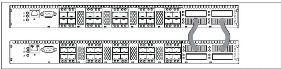
Figure 8 Two-switch stack
Figure 9 shows a three-switch stack of HP StorageWorks SN6000 Fibre Channel Switch switches using two 3-inch and one 9-inch XPAK switch stacking cables. 60 SFP ports are available for devices.
![graph TD A["Server Rack 1"] --> B["Switch"] C["Server Rack 2"] --> B D["Server Rack 3"] --> B B --> E["Server Rack 4"] style A fill:#f9f,stroke:#333 style C fill:#f9f,stroke:#333 style D fill:#f9f,stroke:#333 style E fill:#ccf,stroke:#333](/content/2026/07/1506716/images/fa2534a2e4ac585021b124ef356f463d8621b29e5e31fde80cd884e9fa352eb5.jpg)
Figure 9 Three-switch stack
Figure 10 shows a four-switch stack of model SN6000 switches using three 3-inch and three 9-inch XPAK switch stacking cables. 80 SFP ports are available for devices.
![graph TD A["Server Rack"] --> B["Data Bus"] B --> C["Network Port 1"] B --> D["Network Port 2"] B --> E["Network Port 3"] B --> F["Network Port 4"] style A fill:#f9f,stroke:#333 style B fill:#ccf,stroke:#333 style C fill:#cfc,stroke:#333 style D fill:#fcc,stroke:#333 style E fill:#cff,stroke:#333 st…](/content/2026/07/1506716/images/6479e1da3b03545f28d219dab673d47220aab41a2407ab6ca656fe0781e3a1f8.jpg)
Figure 10 Four-switch stack
Figure 11 shows a five-switch stack of model SN6000 switches using ten XPAK switch stacking cables. 100 SFP ports are available for devices.
![graph TD A["Server Rack 1"] --> B["Node 1"] A --> C["Node 2"] A --> D["Node 3"] A --> E["Node 4"] A --> F["Node 5"] A --> G["Node 6"] A --> H["Node 7"] A --> I["Node 8"] A --> J["Node 9"] A --> K["Node 10"] A --> L["Node 11"] A --> M["Node 12"] A --> N["Node 13"] A --> O["Node 14"] A --> P["Node 15"…](/content/2026/07/1506716/images/7365cf5e2b4fc79b9dc3591ac6b2d69702cf4fb4c65ebe46b5b0169e35845a98.jpg)
Figure 11 Five-switch stack
Figure 12 shows a six-switch stack of model SN6000 switches using eight XPAK switch stacking cables. 120 SFP ports are available for devices.
![graph TD A["Server Rack 1"] --> B["Device Array"] C["Server Rack 2"] --> D["Device Array"] E["Server Rack 3"] --> F["Device Array"] G["Server Rack 4"] --> H["Device Array"] I["Server Rack 5"] --> J["Device Array"] K["Central Network"] --> L["Client 1"] K --> M["Client 2"] K --> N["Client 3"] K --> O…](/content/2026/07/1506716/images/892f758e0208127e057fe56c93c0246388dea4c7ed2753a881815757f18ea690.jpg)
Figure 12 Six-switch stack
Common topologies
Although HP recommends using the XPAK stacking ports to achieve the highest cabling efficiency and bandwidth, you can also create multiple switch configurations using the SFP ports. The HP StorageWorks SN6000 Fibre Channel Switch switch supports the following topologies using the SFP ports:
• Cascaded fabric topology
- Ring fabric topology
- Meshed fabric topology
• Core-edge fabric topology
For additional information about topologies and Storage Area Network (SAN) connectivity, see the SAN Design Reference Guide available at the HP website: http://www.hp.com/go/SANdesignguide.
Transparent routing
IMPORTANT: The Simple SAN Connection Manager (SSCM) application can manage SN6000 Fibre Channel Switches with active TR_Ports; however, SSCM cannot manage or discover remote switches or devices in the remote fabric. Use QuickTools and the storage management interface to present Logical Unit Numbers (LUNs) to remote devices. SSCM displays the remote fabric as a grayed-out switch, and no management can be performed. SSCM version 3.0 or later is required for the HP SN6000 Fibre Channel Switch. SSCM version 2.0 and earlier versions do not support the management of fabrics that include switches with active TR_Ports and may disrupt communication between an SN6000 or 8/20q Fibre Channel Switch and the remote fabric.
The transparent routing feature provides inter-fabric routing to allow controlled and limited access between devices on a SN6000 Fibre Channel Switch (local) fabric and devices on a remote fabric consisting of B-series or C-series switches. For a list of switches that are supported in a remote fabric, see the HP StorageWorks SN6000 Fibre Channel Switch Release Notes, and the HP StorageWorks SAN Design Reference Guide on the HP website: http://www.hp.com/go/sandesignguide. This type of inter-fabric connection uses the Fibre Channel industry N-Port ID Virtualization (NPIV), and makes local and remote devices accessible to each other while maintaining the local and remote fabrics as separate fabrics.
You can connect multiple SN6000 Fibre Channel Switches to one or more remote fabrics using multiple TR_Ports. Local and remote devices are identified by their respective port worldwide names. Consider the following mapping rules:
- A TR_Port can support a maximum of 32 local device/remote device mappings.
- A specific local device can be mapped to devices on only one remote fabric. Local devices on the same SN6000 Fibre Channel Switch can each be mapped to different remote fabrics.
- For mappings between a specific SN6000 Fibre Channel Switch and a remote fabric, each local device or remote device can be mapped over only one TR_Port. Additional mappings to either device must use that same TR_Port.
- Multiple local devices connected to different local switches can be mapped to the same remote device over one TR_Port on each local switch.
- A local device cannot be mapped over an E_Port to another local switch, then over a TR_Port to the remote device. The local switch to which the local device is connected must connect directly to the remote fabric over a TR_Port.
NOTE: When a local device is mapped over a TR_Port to a remote device, the local device and its TR_Port appear as an NPIV connected device in the remote fabric. It is possible, though not recommended, to map such a local device over a second TR_Port to a local device in a second local fabric. In this case, if you merge the two local fabrics, the transparent route becomes inactive for the devices that now have a path over an ISL, and an alarm is generated.
You can configure transparent routing using QuickTools or the CLI, though QuickTools is recommended because it validates your entries, manages the zone mapping for the local fabric, and creates a list of zoning commands that can be run in a script on a HP StorageWorks B-series or C-series SAN switch. For more detailed information, see the HP StorageWorks SN6000 Fibre Channel Switch QuickTools Switch Management User Guide and the HP StorageWorks SN6000 Fibre Channel Switch Command Line Interface Guide.
IMPORTANT: Since C-series switches do not support the Unzoned Name Server, C-series fabrics must be "pre-zoned" before you can set up TR mappings to a remote C-series fabric using the TR Mapping Manager dialog box. The C-series fabric zoneset must be changed to add zones so that the WWNs of the remote devices to be mapped and the WWNs of the SN6000 Fibre Channel Switch TR ports are zoned together. For more information, see the C-series documentation for specific information to configure zoning. Retain these zones in the zoneset after completion of the TR mapping as a best practice, until you no longer need to map the device to the local fabric.
To configure transparent routing using QuickTools:
- Determine what devices on the local fabric require access to devices on the remote fabric. Local devices must be attached directly to the SN6000 Fibre Channel Switch.
- Configure one or more TR_Ports on the local SN6000 Fibre Channel Switch first and then connect the TR_Port to the remote fabric. QuickTools prompts you to configure TR_Ports where existing port connections to remote fabrics have isolated. For remote HP StorageWorks B-series or C-series fabrics, the switch to which the TR_Port connects must support N-Port ID Virtualization (NPIV) and for B-series fabrics the interoperability mode must be configured to InteropMode=0. Other B-series or C-series switches in the remote fabric need not support NPIV.
NOTE: Be sure to configure the TR_Port before connecting the remote fabric to the HP StorageWorks SN6000 Fibre Channel Switch. If the remote fabric is connected to a port on the HP StorageWorks SN6000 Fibre Channel Switch that is not a TR_Port, the two fabrics may establish an E_Port connection and the local and remote fabrics may merge. This mixed fabric is not a supported configuration. If the port type is changed to TR_Port after connecting the remote fabric, a port reset may be required to completely establish the TR connection.
- Map local devices to remote devices and activate the connection. The QuickTools mapping process creates an inter-fabric zone (IFZ) in the active zone set consisting of the local device, the remote device, and the TR_Port. When the mapping is complete, QuickTools activates the new zone set.
The name of the inter-fabric zone begins with IFZ followed by the lowest device port WWN followed by the remaining port WWN, all uppercase, separated by underscores (_). For example, consider the following local and remote device WWNs:
- Local device: 21:00:00:e0:8b:0e:d3:59
- Remote device: 22:00:00:04:cf:a8:7f:2d
The inter-fabric zone name would be:
IFZ_210000E08B0ED359_22000004CFA87F2D
- Apply the same inter-fabric zone that was created on the local fabric to the active zoning on the remote fabric. QuickTools creates a suggested list of commands during the mapping process that, when run on a remote fabric consisting of HP StorageWorks B-series or C-series switches, will make the necessary zoning changes to the remote fabric. See the HP StorageWorks SN6000 Fibre Channel Switch QuickTools Switch Management User Guide for important details on creating and using this list of suggested commands. When modifications to the active zoning on both fabrics are complete, the transparent routing connection becomes active, and the local devices will discover the remote devices.
Switch services
You can configure your switch to suit the demands of your environment by enabling or disabling a variety of switch services. Familiarize yourself with the following switch services and determine which ones you need.
- Telnet: Provides for the management of the switch over a Telnet connection. Disabling this service is not recommended. The default is enabled.
- Secure Shell (SSH): Provides for secure remote connections to the switch using SSH. Your workstation must also use an SSH client. The default is disabled.
- GUI Management: Provides for out-of-band management of the switch with Simple SAN Connection Manager, QuickTools, SNMP, and SMI-S. If this service is disabled, the switch can only be managed inband or through the serial port. The default is enabled.
- Inband Management: Provides for the management of the switch over an inter-switch link using Simple SAN Connection Manager, QuickTools, SNMP, or management server. If you disable inband management, you can no longer communicate with that switch by means other than an Ethernet or serial connection. The default is enabled.
- Secure Socket Layer (SSL): Provides for secure SSL connections for the QuickTools web applet and SMI-S. This service must be enabled to authenticate users through a Remote Authentication Dial-in Service (RADIUS) server. To enable secure SSL connections, you must first synchronize the date and time on the switch and the workstation. Enabling SSL automatically creates a security certificate on the switch. The default is disabled.
- QuickTools web applet (EmbeddedGUI): Provides for access to the QuickTools web applet. QuickTools enables you to point at a switch with an internet browser and manage the switch through the browser. The default is enabled.
- Simple Network Management Protocol (SNMP): Provides for the management of the switch through third-party applications that use the Simple Network Management Protocol (SNMP). Security consists of a read community string and a write community string that serve as passwords that control read and write access to the switch. These strings are set at the factory to these well-known defaults and should be changed if SNMP is to be enabled. Otherwise, you risk unwanted access to the switch. The switch supports SNMP versions 1, 2, and 3. The default configuration enables SNMP and disables SNMP version 3 security.
- Common Information Model (CIM): Provides for the management of the switch through third-party applications that use the Storage Management Initiative–Specification (SMI-S). The default is enabled.
- File Transfer Protocol (FTP): Provides for transferring files rapidly between the workstation and the switch using FTP. The default is enabled.
- Management Server (MS): Enables or disables the management of the switch through third-party applications that use FC-GS-3 Management Server. The default is disabled.
- Call Home:

IMPORTANT: The Call Home service provides an e-mail notification capability for the switch. This service has no relationship with the HP Call Home feature, which notifies only HP services.
Provides for automated e-mail notification of switch status and operating conditions based on specified event severity levels. The default is enabled. The Call Home service requires an Ethernet connection to at least one Simple Mail Transfer Protocol (SMTP) server. You must configure the Call Home service to do the following:
- Enable primary and secondary SMTP servers and specify their IP addresses
- Specify contact information
Configure one or more Call Home profiles to specify e-mail recipients, message format, and the event severity level that will initiate a message. In addition, you can configure periodic event data collection and processing through the Tech_Support_Center profile for automated status and trend analysis.
Security
Security is available at the following levels:
• User account security, page 30
• IP security, page 30
- Port binding, page 30
• Connection security, page 30
• Device security, page 31
User account security
User account security consists of the administration of account names, passwords, expiration date, and authority level. If an account has Admin authority, all management tasks can be performed by that account in the CLI, QuickTools, and Simple SAN Connection Manager. Otherwise only monitoring tasks are available. The default account name, Admin, is the only account that can create or add account names and change passwords of other accounts. All users can change their own passwords. Account names and passwords are always required when connecting to a switch.
Authentication of the user account and password can be performed locally using the switch's user account database or it can be done remotely using a RADIUS server such as Microsoft RADIUS. Authenticating user logins on a RADIUS server requires a secure management connection to the switch. For information about securing the management connection, see "Connection security" on page 30. A RADIUS server can also be used to authenticate devices and other switches as described in "Device security" on page 31.
Consider your management needs and determine the number of user accounts, their authority needs, and expiration dates. Also consider the advantages of centralizing user administration and authentication on a RADIUS server. Use the CLI to configure RADIUS servers. For more information about RADIUS server configuration, see the HP StorageWorks SN6000 Fibre Channel Switch Command Line Interface Guide.
NOTE: If the same user account exists on a switch and its RADIUS server, that user can login with either password, but the authority and account expiration will always come from the switch database.
IP security
IP Security provides encryption-based security for IP version 4 and IP version 6 communications through the use of security policies and associations. Policies can define security for host-to-host, host-to-gateway, and gateway-to-gateway connections; one policy for each direction. For example, to secure the connection between two hosts, you need two policies: one for outbound traffic from the source to the destination, and another for inbound traffic to the source from the destination.
A security association defines which encryption algorithm and encryption key to apply when called by a security policy. A security policy may call several associations at different times, but each association is related to only one policy. When planning IP security, consider the connections to be secured and the encryption methods to be used.
Port binding
Port binding provides authorization for a list of up to 32 switch and device WWNs that are permitted to log in to a particular switch port. Switches or devices that are not among the 32 are refused access to the port. Consider what ports to secure and the set of switches and devices that are permitted to log in to those ports. Use the CLI to configure port binding. For more information about port binding configuration, see the HP StorageWorks SN6000 Fibre Channel Switch Command Line Interface Guide.
Connection security
Connection security provides an encrypted data path for switch management methods. The switch supports the Secure Shell (SSH) protocol for the command line interface and the Secure Socket Layer (SSL) protocol for management applications such as QuickTools and SMI-S. Use the CLI to configure SSH and SSL. For more information about SSH and SSL configuration, see the HP StorageWorks SN6000 Fibre Channel Switch Command Line Interface Guide.
The SSL handshake process between the workstation and the switch involves the exchanging of certificates. These certificates contain the public and private keys that define the encryption. When the SSL service is enabled, a certificate is automatically created on the switch. The workstation validates the switch certificate by comparing the workstation date and time to the switch certificate creation date and time. For this reason, it is important to synchronize the workstation and switch with the same date, time, and time zone. The switch certificate is valid 24 hours before its creation date and 365 days after its creation date. If the certificate should become invalid, create a new certificate using the create certificate CLI command. For information about the create certificate CLI command, see the HP StorageWorks SN6000 Fibre Channel Switch Command Line Interface Guide.
Consider your requirements for connection security: for the command line interface (SSH), management applications (SSL), or both. If an SSL connection security is required, also consider using the Network Time Protocol (NTP) to synchronize workstations and switches.
Device security
Device security provides for the authorization and authentication of devices that you attach to a switch. You can configure a switch with a group of devices against which the switch authorizes new attachments by devices, other switches, or devices issuing management server commands. Device security is configured through the use of security sets and groups. Use the CLI to configure device security. For more information about device security configuration, see the HP StorageWorks SN6000 Fibre Channel Switch Command Line Interface Guide.
A group is a list of device worldwide names that are authorized to attach to a switch. There are three types of groups: one for other switches (ISL), another for devices (port), and a third for devices issuing management server commands (MS).
A security set is a set of up to three groups with no more than one of each group type. The security configuration is made up of all security sets on the switch. The security database has the following limits:
• Maximum number of security sets is 4.
• Maximum number of groups is 16.
• Maximum number of members in a group is 1,000.
• Maximum total number of group members is 1,000.
In addition to authorization, the switch can be configured to require authentication to validate the identity of the connecting switch, device, or host. Authentication can be performed locally using the switch's security database, or remotely using a RADIUS server such as Microsoft RADIUS. With a RADIUS server, the security database for the entire fabric resides on the server. In this way, the security database can be managed centrally, rather than on each switch. You can configure up to five RADIUS servers to provide failover.
You can configure the RADIUS server to authenticate just the switch or both the switch and the initiator device if the device supports authentication. When using a RADIUS server, every switch in the fabric must have a network connection. A RADIUS server can also be configured to authenticate user accounts as described in "User account security" on page 30. A secure connection is required to authenticate user logins with a RADIUS server. For more information, see "Connection security" on page 30.
Consider the devices, switches, and management agents and evaluate the need for authorization and authentication. Also consider whether the security database is to be distributed on the switches or centralized on a RADIUS server and how many servers to configure. Use the CLI to configure RADIUS servers. For more information about RADIUS server configuration, see the HP StorageWorks SN6000 Fibre Channel Switch Command Line Interface Guide.
Fabric management
The Simple SAN Connection Manager application is a GUI-based management application for HP StorageWorks that runs on the management station. It provides basic automated configuration and management of switches, HBAs, and storage devices. Switch management functions include IP address configuration and limited control of zoning. Simple SAN Connection Manager version 3.0 or later is required for the HP SN6000 Fibre Channel Switch.
The browser-based application, QuickTools, and the CLI reside in the switch firmware and provide for the management of individual switches in a single fabric.
Consider how many fabrics and switches will be managed, how many workstations are needed, and whether the fabrics will be managed with Simple SAN Connection Manager, QuickTools, or the CLI.
A switch supports a combined maximum of 19 logins, which are reserved as follows:
- 4 logins or sessions for internal applications, such as management server and SNMP
• 9 high priority Telnet sessions - 6 logins or sessions for Simple SAN Connection Manager inband and out-of-band logins, QuickTools logins, and Telnet logins.
Additional logins will be refused.
3 l n s t a l l a t i o n
This section describes how to install and configure the switch. The following topics are covered:
- Site requirements, page 33
• Installing a switch, page 34
• Installing firmware, page 43 - Adding a switch to an existing fabric, page 45
• Installing feature license keys, page 46 - Configuring Call Home to HP Services (optional), page 46
Site requirements
Consider the following items when installing an SN6000 Fibre Channel Switch:
• Management Station and Workstation requirements, page 33
• Switch power requirements, page 34
• Environmental conditions, page 34
Management Station and Workstation requirements
The management station requirements for Simple SAN Connection Manager are described in Table 6. Workstation requirements for QuickTools are described in Table 7.
Table 6 Management station requirements for Simple SAN Connection Manager
| Operating System | Windows Server 2003 R2 x64/x86 with SP2This requires Microsoft hotfix QFE932755 (updated Storport storage driver). The update is available on the Microsoft website:http://support.microsoft.com/kb/932755Windows Storage Server 2003 R2 x64/x86 with SP2. This requires Microsoft hotfix QFE932755 (updated Storport storage driver). The update is available on the Microsoft website:http://support.microsoft.com/kb/932755Windows Server 2008 x64/x86 with SP1. |
| Memory 512 MB | |
| Disk Space | 200 MB per installation |
| Processor | 2 GHz or faster |
| Internet browser | Microsoft Internet Explorer 5.0 or laterNetscape Navigator 6.0 and laterMozilla 1.5 and laterFirefox 1.0 and laterJava Runtime Environment 1.5 or higher |
| Hardware | CD ROM driveRJ-45 Ethernet portPCI-e slots for the HP StorageWorks PCI-e FC HBA |
Table 7 Workstation requirements for QuickTools
| Operating systems Windows 2003 and XP SP1/SP2Red Hat Enterprise Linux 4, 5SUSE Linux Enterprise Server 9 and 10 | |
| Memory 512 MB | |
| Processor 2 GHz or faster | |
| Internet Browser Microsoft Internet Explorer 6.0 or laterNetscape Navigator 6.0 and laterMozilla 1.5 and laterFirefox 1.5 and laterJava Runtime Environment 1.4.2 or later 1 | |
| Hardware RJ-45 Ethernet port | |
- You must disable caching of temporary files and applets in Java to prevent conflicts with past or future versions of QuickTools. Furthermore, you may need to disable caching again after upgrading Java.
Telnet workstations require an RJ-45 Ethernet port or an RS-232 serial port and an operating system with a Telnet client.
Switch power requirements
Power requirements are 1 Amp at 100 VAC or 0.5 A at 240 VAC.
Environmental conditions
Consider the factors that affect the climate in your facility such as equipment heat dissipation and ventilation. The switch requires the following operating conditions:
- Operating temperature range: 5° - 40°C (41°–104°F)
- Relative humidity: 10–90%, non-condensing
Installing a switch
Unpack the switch and accessories. The SN6000 Fibre Channel Switch product is shipped with the following components
• One Read-Me-First document
• One End User License Agreement (EULA)
- HP StorageWorks 8/20q and SN6000 Fibre Channel Switch Rack-Mount Kit Quick Start Installation Instructions
• HP StorageWorks SN6000 Fibre Channel Switch Quick Start Installation Instructions
• One HP StorageWorks SN6000 Fibre Channel Switch
• One HP StorageWorks 8/20q and SN6000 Fibre Channel Switch Rack-Mount Kit
• One or two standard power cords (depending on the switch model)
• One or two HP Power Distribution Unit (PDU) power cables (depending on the switch model)
- One serial cable
• Four adhesive rubber feet
For the latest product information, including firmware, documentation, and supported SAN configurations, see the following HP website: http://www.hp.com/go/SN6000.
Installing a SN6000 Fibre Channel Switch involves the following steps:
- Mount the switch, page 35
- Install the transceivers, page 39
- Configure the workstation, page 39
- Apply power to the switch, page 40
- Connect the management station or workstation to the switch, page 41
- Configure the switch, page 41
- Cable devices to the switch, page 42
Mount the switch
The switch can be placed on a flat surface and stacked, or mounted in a 19" Electronics Industries Association (EIA) rack. See "Weight and physical dimensions" on page 74 for weight and dimensional specifications. Adhesive rubber feet are provided for surface mounts only. Without the rubber feet, the switch occupies 1U of space in an EIA rack.
The rack mount kit is supported with the following HP custom racks only:
• HP 9000 Series Rack
• HP 10000 Series Rack
• HP 10000 G2 Series Rack
Before you begin
⚠ WARNING! To reduce the risk of personal injury or damage to the equipment, ensure that:
- In single-rack installations, stabilizing feet are attached to the rack.
- In multiple-rack installations, racks are coupled together.
• Leveling jacks on the rack are extended to the floor. - The full weight of the rack rests on the leveling jacks.
- Heavy items, such as uninterruptible power supplies and hard drive storage enclosures, are installed near the bottom of the rack.
- Similar components are installed next to each other in the rack. Because devices are of differing depths, this will facilitate maintenance and service tasks.
- Only one device in a rack is extended at a time. A rack may become unstable if more than one device is extended.
CAUTION:
- For proper airflow, the SFP+ media side (port side) of the device must face the front of the rack. Mounting the switch in this direction allows air to enter from the front of the rack (SFP-port side of switch) and exhaust through the back of the rack (power-supply side of switch). This prevents overheating, which may cause equipment in the rack to fail.
- Allow a minimum of 63.5 cm (25 in.) clearance in front of the rack to allow the doors to open fully, and 76.2 cm (30 in.) in back of the rack to allow for servicing and airflow.
- If the device is mounted in a closed rack or there are multiple rack-mounted devices, make sure that the operating temperature inside the rack enclosure does not exceed the maximum rated ambient temperature.
- Multiple rack-mounted devices connected to the same AC supply circuit may overload that circuit or the AC supply wiring. Consider the power source capacity and the total power usage of all switches on the circuit.
- Reliable grounding in the rack must be maintained.
Collect the required items
NOTE: The rack mount kit installation requires one technician.
Locate the following items and set them aside:
• SN6000 Fibre Channel Switch
• 8/20q and SN6000 Fibre Channel Switch rack-mount kit
- Smaller items, such as screws, ship in plastic bags in the kit. See Table 8.
Required tools:
• #2 Phillips screwdriver
7/16-inch wrench
Verify the kit contents
Check the contents of the SN6000 Fibre Channel Switch rack mount kit shipping carton to verify that all required parts and hardware are available (Table 8).
Table 8 SN6000 Fibre Channel Switch rack mount kit hardware
| Item Description | |
| Two (2) rear mounting brackets | |
| Two (2) switch rails | |
| One (1) filler panel (optional), see step 7. | |
| Ten (10) M6 machine screws | |
| Ten (10) M6 cage-nuts for square rack holes | |
| Ten (10) M6 cage-nuts for round rack holes | |
| Four (4) 10-32 x .375-inch screws with captive washers | |
| Two (2) 1/4-20 hex nuts with lock washers | |
| Two (2) 1/4-inch flat washers |
Rack the switch
- Remove and discard the four 10-32 screws from the sides of the switch.
- Attach each rail to the switch using two 10-32 x .375-inch screws with captive washers (Figure 13). Make sure the slotted ends of the rails are on the power-supply side (not the SFP-port side) of the switch
Figure 13 Attaching the rails to the switch
- On the rack vertical posts, mark the holes that will be used by the rail flanges (three on each rear vertical post, two on each front vertical post). Then, from the inside of each vertical post, insert an M6 cage-nut for the rack you are using (square or round hole) into each marked hole (Figure 14). Fasten each rear mounting bracket to the marked holes, using two M6 machine screws.
Figure 14 Installing the rear mounting brackets
- Place the switch and rail assembly into the rack through the front, guiding the slotted-rail ends onto the threaded studs of the rear mounting brackets (Figure 15). Fit the posts on the front rail flanges in the holes between the two cage-nuts on each of the front vertical rack posts.
Figure 15 Installing the switch and rail assembly
- Fasten each rail flange to the front of the rack using two M6 machine screws (Figure 16).
Figure 16 Fastening the rail to the front of the rack
- Fasten each slotted-rail end to the rear mounting bracket using a flat washer and a 1/4-20 hex nut (Figure 17).
Figure 17 Fastening the rail to the rear mounting bracket
- Optional: Fasten the filler panel to the rear mounting brackets with two M6 machine screws (Figure 18).
Figure 18 Installing the filler panel
Install the transceivers
A small form-factor pluggable (SFP) transceiver is required for each switch port connected to a device or another switch. SFPs are not included with the switch. An XPAK transceiver is required for each switch 10 Gb/s port connected to the 10 Gb/s port of another switch. Only HP transceivers are supported for use in the switch. To install an transceiver, insert the transceiver into any of the active switch ports and gently press until it snaps in place. To remove a transceiver, gently press the transceiver into the port to release the tension, then pull on the release tab or lever and remove the transceiver.
TIP: The transceiver fits only one way. If the transceiver is not installed under gentle pressure, invert it and try again. A new switch has all ports active.
Configure the workstation
NOTE: If you plan to use Simple SAN Connection Manager or QuickTools to manage the switch, proceed to "Apply power to the switch" on page 40.
If you plan to use the CLI to configure and manage the switch, you must configure the workstation. This involves setting the workstation IP address for Ethernet connections, or configuring the workstation serial port.
Configuring the workstation IP address for Ethernet connections
The default IP address of a new switch is 10.0.0.1. To ensure that your workstation is configured to communicate with the 10.0.0 subnet:
• For a Windows workstation:
a. Click Start, then choose Settings > Control Panel > Network and Dial-Up Connections.
b. Choose Make New Connection.
c. Click the Connect to a private network through the Internet radio button, then click Next.
d. Enter 10.0.0.253 for the IP address.
- For a Linux workstation, open a command window and enter the following command where interface is your interface name:
ifconfig interface ipaddress 10.0.0.253 netmask 255.255.255.0 up
Configuring the workstation serial port
To configure the workstation serial port:
- Connect a null modem F/F DB9 cable from a COM port on the workstation to the RS-232 serial port on the switch.
- Configure the workstation serial port according to your platform:
For a Windows workstation:
a. Open the HyperTerminal application. Click Start, then select Programs > Accessories > Communications > HyperTerminal.
b. Enter a name for the switch connection and choose an icon in the Connection Description window. Click OK.
c. Enter the following COM Port settings in the COM Properties window, and click OK.
- Bits per second: 9,600
- Data Bits: 8
- Parity: None
- Stop Bits: 1
- Flow Control: None
For a Linux workstation:
a. Set up minicom to use the serial port. Create or modify the /etc/minirc.dfl file with the following content.
b. Verify that all users have permission to run minicom. Review the /etc/minicom.users file and confirm that the line ALL exists or that there are specific user entries.
Apply power to the switch
WARNING! This product is supplied with a 3-wire power cable and plug for the user's safety. Use this power cable in conjunction with a properly grounded outlet to avoid electrical shock. An electrical outlet that is not correctly wired could place hazardous voltage on metal parts of the switch. It is the responsibility of the customer to ensure that the outlet is correctly wired and grounded to prevent electrical shock.
You may require a different power cable in some countries because the plug on the cable supplied with the equipment will not fit your electrical outlet. In this case, you must supply your own power cable. The cable you use must meet the following requirements:
- For 125 Volt electrical service, the cable must be rated at 10 Amps and be approved by Underwriters Laboratories (UL) and Canadian Standards Association (CSA).
- For 250 Volt electrical service: The cable must be rated at 10 Amps, meet the requirements of H05VV-F, and be approved by Verband der Elektrotechnik (VDE), SEMKO, and DEMKO.
To power up a SN6000 Fibre Channel Switch, attach the AC power cord to the receptacle on the back of the switch and to the power source.
The switch runs its self-tests and begins normal operation—this may take a few minutes:
- The switch LEDs (Input Power, Heartbeat, System Fault) illuminate followed by all port Logged-in LEDs. The Logged-in LEDs that illuminate indicate the ports that are enabled.
- After a couple of seconds, the System Fault LED is extinguished while the Input Power LED and Heartbeat LED remain illuminated.
- After approximately one minute, the POST executes and the Heartbeat LED is extinguished.
- After about another minute, the POST is complete, all LEDs are extinguished, except the Input Power LED and the Heartbeat LED:
- The Input Power LED remains illuminated indicating that the switch logic circuitry is receiving DC voltage. If not, contact your authorized maintenance provider.
- The Heartbeat LED indicates the results of the POST. The POST tests the condition of firmware, memories, data-paths, and switch logic circuitry. If the Heartbeat LED blinks steadily about once per second, the POST was successful, and you can continue with the installation process. Any other blink pattern indicates that an error has occurred. For more information, see "Heartbeat LED blink patterns" on page 52.
Connect the management station or workstation to the switch
You can manage the switch using the Simple SAN Connection Manager, QuickTools, or the CLI. Simple SAN Connection Manager requires at least one FC connection and an Ethernet connection to the switch. QuickTools requires an Ethernet connection to the switch. The CLI can use an Ethernet connection or a serial connection.
- If this switch is part of the 8Gb Simple SAN Connectivity Kit installation:
a. Connect at least one FC cable from the management station to the switch, or to another switch in the same fabric.
b. Use a 10/100 Base-T straight cable to connect the switch Ethernet port to the LAN that connects your management station that will run Simple SAN Connection Manager (see Indirect Ethernet in Figure 19).
- If this switch is a standalone installation and you plan to use QuickTools or the CLI, connect the switch Ethernet port to the workstation, in one of the following ways:
- Indirect Ethernet connection from the workstation to the switch RJ-45 Ethernet connector through an Ethernet switch or a hub. This requires a 10/100 Base-T straight cable (Figure 19).
- Direct Ethernet connection from the workstation to the switch RJ-45 Ethernet connector. This requires a 10/100 Base-T cross-over cable (Figure 19).
- Serial port connection from the workstation to the switch RS-232 serial port connector. This requires a null modem F/F DB9 cable (Figure 19). This connection supports the CLI only.
1 Indirect Ethernet RJ-45 connection
2 Direct Ethernet RJ-45 connection
3 Serial RS-232 connection
Figure 19 Management station and workstation cable connections
Configure the switch
You can configure the switch using Simple SAN Connection Manager, QuickTools, or the CLI.
Simple SAN Connection Manager switch configuration
For information about installing the Simple SAN Connection Manager application, see the HP StorageWorks 8Gb Simple SAN Connection Kit Quick Start Instructions. The Simple SAN Connection Manager software will prompt you to set the switch IP address, administrator password, and default zoning when you first start that application.
When the configuration is complete, proceed to "Cable devices to the switch" on page 42.
QuickTools switch configuration
To log in and configure the switch using QuickTools:
- Open an Internet browser and enter the default IP address 10.0.0.1 to start the QuickTools web applet.
- Log in to the switch using the default user name (admin) and password (password).
- Obtain the IP address and subnet mask from your network administrator.
- Open the QuickTools Wizards menu and select Configuration Wizard. Follow the instructions to set the IP address and the password. Changing the IP address will terminate the QuickTools session.
- Open an Internet browser again and log in with the new IP address.
- When the configuration is complete, proceed to "Cable devices to the switch" on page 42.
CLI switch configuration
To configure the switch using the command line interface.
- Open a command window according to the type of workstation and connection.
For an Ethernet connection (all platforms), open a Telnet session with the default switch IP address and log in to the switch with default account name and password (admin/password).
NOTE: To insure user account security, change the password for the Admin account name. See the passwd command in the HP StorageWorks SN6000 Fibre Channel Switch Command Line Interface Guide.
For a Windows serial connection, open the HyperTerminal application on a Windows platform.
a. Click Start, then select Programs > Accessories > Communications > HyperTerminal.
b. Select the connection you created earlier and click OK. See "Configuring the workstation serial port" on page 39.
For a Linux serial connection, open a command window and enter the following command: minicom
- Open an admin session and enter the set setup system CLI command. Enter the values you want for switch IP address (EthNetworkAddress) and the network mask (EthNetworkMask). For more information about CLI commands, see the HP StorageWorks SN6000 Fibre Channel Switch Command Line Interface Guide.
SN6000 FC Switch#> admin start
SN6000 FC Switch (admin) #> set setup system
- Open a Config Edit session and use the set config switch CLI command to modify the switch configuration.
- When the configuration is complete, proceed to "Cable devices to the switch" on page 42.
Cable devices to the switch
Connect cables to the SFP transceivers and their corresponding devices, and then energize the devices. Device host bus adapters can have SFP (or SFF) transceivers. Duplex cable connectors are keyed to ensure proper orientation. Choose the Fibre Channel cables with the connector combination that matches the device host bus adapter.
GL_Ports self configure as FL_Ports when connected to loop of devices or F_Ports when connected to a single device. G_Ports self-configure as F_Ports when connected to a single device. Both GL_Ports and G_Ports self-configure as E_Ports when connected to another switch.
Installing firmware
The switch comes with current firmware installed. You can upgrade the firmware from the management station or workstation as new firmware becomes available using Simple SAN Connection Manager, QuickTools, or the CLI. This guide describes the use of QuickTools and the CLI. For information about installing firmware using Simple SAN Connection Manager, see the HP StorageWorks Simple SAN Connection Manager User Guide.
• Using QuickTools to install firmware, page 43
• Using the CLI to install firmware, page 44
You can load and activate firmware upgrades on an operating switch without disrupting data traffic or re-initializing attached devices. If you attempt to perform a non-disruptive activation without satisfying the following conditions, the activation will fail. If the non-disruptive activation fails, you will usually be prompted to try again later. Otherwise, the switch will perform a disruptive activation.
- The current firmware version supports the installation and non-disruptive activation of the new firmware. For information about compatible firmware versions, see the firmware release notes.
- No changes are being made to switches in the fabric including powering up, powering down, disconnecting or connecting ISLs, changing switch configurations, or installing firmware.
- No port in the fabric is in the diagnostic state.
- No Zoning Edit sessions are open in the fabric.
- No changes are being made to attached devices including powering up, powering down, disconnecting, connecting, and HBA configuration changes.
If you are installing firmware on more than one switch in the fabric, wait until the activation is complete on the first switch before installing firmware on a second switch. If you attempt to activate firmware on a second switch before activation is complete on the first, you will receive a message advising you to wait and perform a hot reset later on the second switch to complete the installation.
Ports that are stable when the non-disruptive activation begins and then change states, will be reset. When the non-disruptive activation is complete, Simple SAN Connection Manager and QuickTools sessions reconnect automatically. However, Telnet sessions must be restarted manually.
TIP: After upgrading firmware that includes changes to QuickTools, an open QuickTools session may indicate that the firmware is not supported. This means the new firmware is not supported by the previous QuickTools version. To correct this, close the QuickTools session and the browser window, then open a new QuickTools session.
Using QuickTools to install firmware
To install firmware using QuickTools:
- In the faceplate display, open the Switch menu and select Load Firmware.
- In the Load Firmware dialog, choose one of the following:
- Select a firmware image file from the Version drop-down list.
- Click Browse to change the folder (path) to search for firmware image files. Click Rescan to search the new folder displayed in the Firmware Image Folder field.
- Click Start to begin the firmware load process. You will be shown a message warning you that the switch will be reset to activate the firmware.
- Click OK to continue firmware installation.
- Click Close to close the Load Firmware dialog.
Using the CLI to install firmware
The method you choose to install firmware using the CLI depends on the type of firmware activation you want.
- For a disruptive activation, enter the firmware install or image install command to download the firmware image file from an FTP or TFTP server, unpack it, and activate it in one step. See "One-step firmware installation" on page 44.
- For a non-disruptive activation, enter the image fetch command to download the firmware image file from an FTP or TFTP server. Enter the image unpack command to unpack the image file, then enter the hotreset command to perform a non-disruptive activation. See "Custom firmware installation" on page 45.
For information about the CLI commands, see the HP StorageWorks SN6000 Fibre Channel Switch Command Line Interface Guide.
One-step firmware installation
The firmware install and image install commands download the firmware image file from an FTP or TFTP server to the switch, unpack the image file, and perform a disruptive activation in one step. The installation process prompts you to enter the following:
• The file transfer protocol (FTP or TFTP)
• IP address of the remote host
- An account name and password on the remote host (FTP only)
• Pathname for the firmware image file
For information about the CLI commands, see the HP StorageWorks SN6000 Fibre Channel Switch Command Line Interface Guide.
- Enter the following commands to download the firmware from a remote host to the switch, install the firmware, then reset the switch to activate the firmware.
SN6000 FC Switch #> admin start
SN6000 FC Switch #> firmware install
The switch will be reset. This process will cause a disruption to I/O traffic.
Continuing with this action will terminate all management sessions, including any Telnet sessions. When the firmware activation is complete, you may log in to the switch again.
Do you want to continue? [y/n]: y
Press 'q' and the ENTER key to abort this command.
- Enter your choice for the file transfer protocol with which to download the firmware image file. FTP requires an user account and a password; TFTP does not.
FTP or TFTP : ftp
- Enter your account name on the remote host (FTP only) and the IP address of the remote host. When prompted for the source file name, enter the path for the firmware image file.
User Account : johndoe
IP Address : 10.0.0.254
Source Filename : 8.0.00.11_epc
About to install image. Do you want to continue? [y/n] y
- When prompted to install the new firmware, enter y to continue or n to cancel. Entering y will disrupt traffic. This is the last opportunity to cancel.
About to install image. Do you want to continue? [y/n] y
Connected to 10.20.20.200 (10.20.20.200).
220 localhost.localdomain FTP server (Version wu-2.6.1-18) ready.
- Enter the password for your account name (FTP only).
331 Password required for johndoe.
Password:*****
230 User johndoe logged in.
The firmware will now be downloaded from the remote host to the switch, installed, and activated.
Custom firmware installation
A custom firmware installation downloads the firmware image file from an FTP or TFTP server to the switch, unpacks the image file, and resets the switch in separate steps. This allows you to choose the type of switch reset and whether the activation will be disruptive (reset switch command) or nondisruptive (hotreset command). The following example illustrates a custom firmware installation with a nondisruptive activation.
- Download the firmware image file from the server to the switch.
• If your server has an FTP server, you can enter the image fetch command:
SN6000 FC Switch (admin) #> image fetch account_name ip_address filename
- If your server has a TFTP server, you can enter the image tftp command to download the firmware image file.
SN6000 FC Switch (admin) #> image tftp ip_address filename
- If your server has neither an FTP nor a TFTP server, open an FTP session and enter FTP commands:
>ftp ip_address or switchname
user:images
password: images
ftp>bin
ftp>put filename
ftp>quit
- Display the list of firmware image files on the switch to confirm that the file was loaded.
SN6000 FC Switch (admin) \$>image list
- Unpack the firmware image file to install the new firmware in flash memory.
SN6000 FC Switch (admin) \$>image unpack filename
- Wait for the unpack to complete.
image unpack command result: Passed
- A message will prompt you to reset the switch to activate the firmware. Use the hotreset command to attempt a non-disruptive activation.
SN6000 FC Switch (admin) \$>hotreset
Adding a switch to an existing fabric
If there are no special conditions to be configured for the new switch, plug in the switch. The switch becomes functional with the default fabric configuration. The default fabric configuration settings are as follows:
- Fabric zoning is sent to the switch from the fabric.
- All ports will be GL_Ports.
- The default IP address 10.0.0.1 is assigned to the switch without a gateway or boot protocol configured: Reverse Address Resolution Protocol (RARP) Bootstrap Protocol (BOOTP), and Dynamic Host Configuration Protocol (DHCP).
If you are adding a switch to a fabric and do not want to accept the default fabric configuration:
-
If the switch is not new from the factory, reset the switch to the factory configuration before adding the switch to the fabric.
-
If you want to manage the switch through the Ethernet port, you must first configure the IP address.
-
Plug in the inter-switch links (ISL), but do not connect the devices.
-
Configure the port types for the new switch. The ports can be G_Port, GL_Port, F_Port, FL_Port, TR_Port, or Donor.
- Connect the devices to the switch.
- Make any necessary zoning changes.
Installing feature license keys
For information about available license keys, see "Feature licenses" on page 23. To install a license key using QuickTools:
- Open the Switch Menu and select Features to open the Feature Licenses dialog.
- In the Feature Licenses dialog, click Add to open the Add License Key dialog.
- In the Add License Key dialog, enter the license key in the Key field.
- Click Get Description to display the upgrade description.
- Click Add to upgrade the switch. Allow a minute or two for the upgrade to complete.
To upgrade a switch using the command line interface, see the feature command in the HP StorageWorks SN6000 Fibre Channel Switch Command Line Interface Guide.
Configuring Call Home to HP Services (optional)
Call Home to HP Services is supported for the SN6000 Fibre Channel Switch.
- If you have already configured Call Home to HP Services for other HP products using Remote Support Client (RSC), which is part of the Remote Support Pack (RSP), or using Instant Support Enterprise Edition (ISEE), then to configure Call Home to HP Services for the SN6000 Fibre Channel Switch, you must add the switch as a managed system to HP Open Service Event Manager (OSEM) and then configure SNMP traps in the switch.
- If you have not already configured Call Home to HP Services, then you must set up a Central Management Server (CMS) to run HP Systems Insight Manager (SIM), which will direct the installation of RSP applications to support Call Home to HP Services.
Role of the Remote Support Software Manager
When you install RSP, Remote Support Software Manager (RSSWM) is also installed on your CMS. RSSWM downloads required and recommended software components, including the required software components listed below, which are used to allow communication with HP Services, contract and warranty entitlement capabilities and to provide on-site analysis.
• Remote Support Client (RSC)
• Remote Support Common Components (MC3)
• Remote Support Eligible Systems List
- Open Service Event Manager (OSEM)
• Web-Based Enterprise Services (WEBES)
These and other software management options you select are downloaded by RSSWM. Once configured, RSSWM will download and install updated versions as they become available according to the policies selected during the configuration of RSSWM.
Role of OSEM and versions required
OSEM collects and formats problem reports from various HP customer systems, including the SN6000 Fibre Channel Switch. OSEM uses the Ethernet (LAN) connection on the switches to receive event notifications through SNMP traps sent from the switches, and then sends automated notification messages to local e-mail recipients (if so configured) and to HP Services through RSC or ISEE. These applications, in turn, send the event message over the internet to HP Services.
OSEM version 1.4.5, SIM 5.1 (which includes RSP version 5.05), and ISEE version A.03.95 are the minimum versions required to support SN6000 Fibre Channel Switch Call Home to HP Services.
Installation instructions and documentation for SIM, RSP, OSEM, and ISEE
Software, installation instructions, release notes, and other documentation for SIM, RSP, OSEM, and ISEE Standard Configuration are available at no charge from the following HP websites:
• For SIM at http://www.hp.com/go/hpsim
• For RSP at http://www.hp.com/go/ServiceEssentials
• For OSEM at http://h18023.www1.hp.com/support/svctools/OSEM/index.html
• For ISEE at http://www.hp.com/hps/tech/resources/elect/isee.htm
RSP requirements for the CMS
RSP requires that the CMS be a Windows-based system with the following characteristics:
Hardware:
• Any HP ProLiant x86 or HP ProLiant x64 system
• 2.4-GHz processor minimum
- 3 GB RAM minimum; 4 GB RAM if more than 100 devices to be monitored
- 500 MB free disk space minimum
Operating system:
• Microsoft Windows 2000 Server, SP4 for x86
• Microsoft Windows 2000 Advanced Server, SP4 for X86
- Microsoft Windows Server 2003 Standard or Enterprise Edition for x86 with SP1 (running on x86 or x64/AMD64 platforms)
• Microsoft Windows Server 2003 for x64
• Microsoft Windows 2003 SMB, with SP1
• Microsoft Windows 2003 Server with installed Multilingual User Interface Pack (MUI)
• Microsoft Windows 2003 Server with English, French, Italian, German, Spanish and Dutch International Server
Supported Web browsers:
• Internet Explorer, Version 6.0 and 7.0
- Mozilla, Versions 1.5, 1.6, and 1.7
- Firefox, Versions 1.0.2, 1.5, and 2.0
Applications:
• Java Virtual Machine plug-in for Internet Explorer

NOTE: Java plug-in is not installed by default in the Internet Explorer Web Browser for 32-bit and x64 editions of Windows Server 2003.
Infrastructure requirements for implementing Call Home to HP Services
To implement Call Home to HP Services, the following infrastructure requirements must be met:
- Internet access to the Central Management Server running RSC, or a server running ISEE. (Required because notification messages are sent by RSC or ISEE to HP over the Internet.)
- OSEM can run on the same server as RSC or ISEE or on a server that has LAN access to the server running RSC or ISEE.
- The server running OSEM must have LAN access to the SN6000 Fibre Channel Switches to receive SNMP traps from the switches.
- If a fire wall is installed, the following ports must be open:
- Port 162, which receives SNMP traps from the switches, because OSEM uses Microsoft SNMP services
- Port 2069, to communicate with web browsers seeking remote access to OSEM
Configuring Call Home to HP services
To configure Call Home to HP services:
- Make sure SIM and RSC, or ISEE are installed on a server that has Internet access. For software, installation instructions, and other documentation for SIM, RSP, and ISEE Standard Configuration, see the HP websites listed in "Installation instructions and documentation for SIM, RSP, OSEM, and ISEE" on page 47.
- Make sure OSEM is installed on a server that has Ethernet access to the server running SIM and RSC or ISEE, and to the SN6000 Fibre Channel Switches.

NOTE: OSEM can also be installed on the server that is used to run ISEE or SIM and RSC.
- To enable a switch to Call Home to HP Services, configure an SNMP trap in the switch using QuickTools or the CLI, as described in the following procedures:
To configure an SNMP trap using QuickTools:
a. Enter the IP address of the switch into the web browser of a server that has LAN access to the switch, and login to the switch.
b. To open the SNMP Properties dialog box: In the fabric tree, click the switch graphic for the switch you are configuring to open its faceplate display, and then select Switch > SNMP Properties.
c. In the SNMP Properties dialog, select the tab for a trap that is not currently in use.
d. In the display for the selected trap, select the Trap Enabled checkbox to enable the trap.
e. In the Trap Version field, select the trap version V1.
f. In the Trap Severity field, select Critical.
g. In the Trap Address field, enter the IP address of the server running OSEM.
h. In the Trap Port field, enter the trap port number used by OSEM (the OSEM default trap port is 162).
i. In the Trap Community field, enter the trap community name. The name can be up to 32 characters and must agree with the community name used in the OSEM application. The following characters may not be used in the user-defined fields: pound sign (#), semi-colon (;), and comma (,).
j. Click OK to enable the changes.
For more information about QuickTools, see the HP StorageWorks SN6000 Fibre Channel Switch QuickTools Switch Management User Guide.
To configure an SNMP trap using the CLI:
a. Telnet to the IP address of the switch from a server that has LAN access to the switch, and login to the switch.
b. To modify the SNMP configuration, open an admin session and enter the set setup snmp trap CLI command. This will display the current configuration of SNMP trap parameters, followed by queries to allow changes to these parameters. Enter changes as needed to the trap enabled state, IP address, port number, severity, version, and community name.
The following example configures SNMP trap 1:
SN6000 FC Switch #> admin start
SN6000 FC Switch (admin) #> set setup snmp trap 1
A list of attributes with formatting and current values will follow.
Enter a new value or simply press the ENTER key to accept the current value.
If you wish to terminate this process before reaching the end of the list press 'q' or 'Q' and the ENTER key to do so.
Current Values:
Trap1Enabled False
Trap1Address 10.0.0.254
Trap1Port 162
Trap1Severity warning
Trap1Version 2
Trap1Community public
New Value (press ENTER to not specify value, 'q' to quit):
Trap1Enabled (True / False) : True
Trap1Address (hostname, IPv4, or IPv6 Address) : 10.20.30.40
Trap1Port (decimal value, 1-65535) :
Trap1Severity (select a severity level)
1=unknown 6=warning
2=emergency 7=notify
3=alert 8=info
4=critical 9=debug
5=error 10=mark : 4
Trap1Version (1 / 2) : 1
Trap1Community (string, max=32 chars) : OSEMcommunity
Do you want to save and activate this snmp setup? (y/n): [n]
For more information about CLI commands, see the HP StorageWorks SN6000 Fibre Channel Switch Command Line Interface Guide.
- Configure the switches in OSEM by adding each SN6000 Fibre Channel Switch as a Managed System configured with System Type set to FC Switch and the IP address for the switch. For detailed instructions, see the OSEM documentation available at the websites listed in "Installation instructions and documentation for SIM, RSP, OSEM, and ISEE" on page 47.
4 Diagnostics and troubleshooting
Diagnostic information about the switch is available through the switch LEDs and the port LEDs. Diagnostic information is also available through the CLI, QuickTools, or Simple SAN Connection Manager event logs and error displays. This section describes the following types of diagnostics:
- Switch diagnostics, page 51 describes the Input Power LED and System Fault LED indications.
• Power-On self test diagnostics, page 52 describes the Heartbeat LED and the port Logged-in LED indications.
• Transceiver diagnostics, page 56 lists the transceiver diagnostic information that is available.
This section also describes using maintenance mode to recover a disabled switch. See "Recovering a switch using maintenance mode" on page 57.
Switch diagnostics
The SN6000 Fibre Channel Switch has three switch LEDs that are used for diagnostics: Input Power LED, Heartbeat LED, and the System Fault LED (Figure 20).

1 Input Power LED
2 System Fault LED
3 Heartbeat LED
Figure 20 Switch LEDs
The following conditions are described in this section:
• Input power LED is extinguished, page 51
• System fault LED is illuminated, page 52
Input power LED is extinguished
The Input Power LED illuminates to indicate that the switch logic circuitry is receiving proper voltages. If the Input Power LED is extinguished:
- Inspect the power cords and connectors. Is the cord unplugged? Is the cord or connector damaged?
- Yes—Make necessary corrections or repairs. If the condition remains, continue.
• No - Continue.
- Inspect the AC power source. Is the power source delivering the proper voltage?
- Yes - Continue.
- No—Make necessary repairs. If the condition remains, contact your authorized maintenance provider.
System fault LED is illuminated
The System Fault LED illuminates to indicate that a fault exists in the switch firmware or hardware. If the System Fault LED illuminates, identify the Heartbeat LED error blink pattern and take the necessary actions. See "Heartbeat LED blink patterns" on page 52.
Power-On self test diagnostics
The switch performs a series of tests as part of its power-up procedure. The POST diagnostic program performs the following tests:
- Checksum tests on the boot firmware in Programmable read-only memory (PROM) and the switch firmware in flash memory
- Internal data loopback test on all ports
- Access and integrity test on the Application-specific integrated circuit (ASIC)
During the POST, the switch logs any errors encountered. Some POST errors are critical, others are not. The switch uses the Heartbeat LED and the Logged-in LED to indicate switch and port status. A critical error disables the switch so that it will not operate. A non-critical error allows the switch to operate, but disables the ports that have errors. If two or more ports fail the POST, the entire switch is disabled. Whether the problem is critical or not, contact your authorized maintenance provider.
If there are no errors, the Heartbeat LED blinks at a steady rate of once per second. If a critical error occurs, the Heartbeat LED will show a blink pattern that indicates an error, and the System Fault LED will illuminate. If there are non-critical errors, the switch disables the failed ports and flashes the associated Logged-in LEDs. For more information, see "Heartbeat LED blink patterns" on page 52.
Heartbeat LED blink patterns
The Heartbeat LED indicates the operational status of the switch. When the POST completes with no errors, the Heartbeat LED blinks at steady rate of once per second. When the switch is in maintenance mode, the Heartbeat LED illuminates continuously. For more information, see "Recovering a switch using maintenance mode" on page 57. All other blink patterns indicate critical errors. In addition to producing a Heartbeat error blink patterns, a critical error also illuminates the System Fault LED.
The Heartbeat LED shows an error blink pattern for the following conditions:
• 1 blink—Normal operation
• 2 blinks—Internal firmware failure blink pattern, page 52
• 3 blinks—Fatal POST error blink pattern, page 53
• 4 blinks—Configuration file system error blink pattern, page 53
- 5 blinks—Over-temperature blink pattern, page 53
Internal firmware failure blink pattern
An internal firmware failure blink pattern is 2 blinks followed by a two second pause. The 2-blink error pattern indicates that the firmware has failed, and that the switch must be reset. Momentarily press and release the Maintenance button to reset the switch.

Fatal POST error blink pattern
A system error blink pattern is 3 blinks followed by a 2-second pause. The 3-blink error pattern indicates that a POST failure or a system error has left the switch inoperable. If a system error occurs, contact your authorized maintenance provider. Momentarily press and release the Maintenance button to reset the switch.

Configuration file system error blink pattern
A configuration file system error blink pattern is 4 blinks followed by a 2-second pause. The 4-blink error pattern indicates that a configuration file system error has occurred, and that the configuration file must be restored.

To restore the switch configuration:
- Establish communications with the switch using Telnet. Enter one of the following on the command line:
telnet xxx.xxx.xxx.xxx
or
telnet switchname
where xxx.xxx.xxx.xxx is the switch IP address and switchname is the switch name associated with the IP address.
-
A Telnet window opens prompting you for a login. Enter an account name and password. The default account name and password are admin and password respectively.
-
Open an admin session to acquire the necessary authority.
SN6000 \$> admin start
- Restore the configuration. When the restore is complete, the switch will reset.
SN6000 (admin) \$> config restore
If a configuration does not exist, enter the config backup CLI command, then enter the config restore command.
Over-temperature blink pattern
An over-temperature blink pattern is 5 blinks followed by a 2-second pause. The 5-blink error pattern indicates that the air temperature inside the switch has exceeded the failure temperature threshold.

If the Heartbeat LED shows the over-temperature blink pattern:
- Inspect the switch vents. Are the intake and exhaust vents clear?
- Yes - Continue.
- No—Remove any debris from fan intake and exhaust if necessary. If the condition remains, continue.
- Consider the ambient air temperature near the switch and clearance around the switch. Make necessary corrections. If the condition remains, power down the switch and contact your authorized maintenance provider.
Logged-in LED indications
Port diagnostics are indicated by the Logged-in LED for each port (Figure 21).

1 Logged-in LED (port 0)
2 Logged-in LED (port 10)
Figure 21 Logged-in LED
The Logged-in LED has three indications:
• Continuous illumination: A device is logged in to the port.
- Flashing once per second: A device is logging in to the port, or the port is in the diagnostics state.
- Flashing twice per second: The port is down, offline, or an error has occurred.
If a Logged-in LED is flashing two times per second, review the event browser for alarm messages regarding the affected port. You can also inspect the alarm log using the command line interface, show alarm command. If there is an error, alarm messages may point to one or more of the following conditions:
• E_Port isolation, page 54
• Excessive port errors, page 55
E_Port isolation
A Logged-in LED error indication is often the result of E_Port isolation. E_Port isolation can be caused by the following:
• Security failure
- A port configured as an F_Port or an FL_Port is connected to another switch
• Conflicting domain IDs
• Conflicting timeout values
• Conflicting zone membership between active zone sets
- Connection to a B-series or C-series switch
Using QuickTools, review the event browser, and perform the following procedure to diagnose and correct an isolated E_Port:
- Does the QuickTools event browser show an alarm about an invalid attach on the affected port?
- Yes—If you have configured device security, review the ISL group in the active security set to ensure that the membership includes the necessary ports and that the secrets on all switches are correct.
- No - Continue.
- Does the QuickTools event browser show a repeating alarm about an unsupported E_Port command on the affected port?
- Yes—The port is configured as an FL_Port and connected to another switch. Correct the port connection or the port type.
• No - Continue.
-
Display the fabric domain IDs using the show domains CLI command or by selecting the QuickTools Switch tab, Summary icon. Are all domain IDs in the fabric unique?
-
Yes - Continue.
-
No—Correct the domain IDs on the offending switches using the set config switch CLI command or the QuickTools Switch Properties dialog. Reset the port. If the condition remains, continue.
-
Compare the RA_TOV and ED_TOV timeout values for all switches in the fabric using the show config switch CLI command or by selecting the QuickTools Switch tab, Advanced icon. Is each timeout value the same on every switch?
-
Yes - Continue.
-
No—Correct the timeout values on the offending switches using the set config switch CLI command or selecting Switch>Advanced Switch Properties in QuickTools. Reset the port. If the condition remains, continue.
-
Display the active zone set on each switch using the zoning active CLI command or by selecting the QuickTools Active Zoneset tab. Compare the zone membership between the two active zone sets. Are they the same?
- Yes—Contact your authorized maintenance provider.
- No—Deactivate one of the active zone sets or edit the conflicting zones so that their membership is the same, then reset the port. If the condition remains, contact your authorized maintenance provider.

NOTE: E_Port isolation can be caused by merging two fabrics whose active zone sets have two zones with the same name, but different membership.
-
Is the port connected to a switch that supports connection to a TR_Port of an SN6000 Fibre Channel Switch?
-
Yes—Configure the port as a TR_Port and map the local and remote fabric devices.
- No—Contact your authorized maintenance provider.
Excessive port errors
The switch can monitor a set of port errors and generate alarms based on user-defined sample windows and thresholds. These port errors include the following:
• Cyclic Redundancy Check (CRC) errors
- Decode errors
• ISL connection count
• Device login errors
• Device logout errors
- Loss-of-signal errors
Port threshold alarm monitoring is disabled by default. For information about managing port threshold alarms, see the HP StorageWorks SN6000 Fibre Channel Switch Command Line Interface Guide.
If the count for any of these errors exceeds the rising trigger for three consecutive sample windows, the switch generates an alarm and disables the affected port, changing its operational state to "down." Port errors can be caused by the following:
- Triggers are too low or the sample window is too small
• Faulty Fibre Channel port cable - Faulty SFP
- Faulty port
- Faulty device or HBA
Review the event browser to determine if excessive port errors are responsible for disabling the port. Look for a message that mentions one of the monitored error types indicating that the port has been disabled, then perform the following procedure:
-
Examine the alarm configuration for the associated error using the show config threshold CLI command. See the show config threshold CLI command in the HP StorageWorks SN6000 Fibre Channel Switch Command Line Interface Guide. Are the thresholds and sample window correct?
-
Yes - Continue
-
No—Correct the alarm configuration. If the condition remains, continue.
-
Reset the port, then perform an external port loopback test to validate the port and the SFP. For information about testing ports, see the HP StorageWorks SN6000 Fibre Channel Switch Command Line Interface Guide or the HP StorageWorks SN6000 Fibre Channel Switch QuickTools Switch Management User Guide. Does the port pass the test?
-
Yes - Continue
-
No—Replace the SFP and repeat the test. If the port does not pass the test, contact your authorized maintenance provider. Otherwise continue.
-
Replace the Fibre Channel port cable. Is the problem corrected?
-
Yes—The procedure is complete.
-
No - Continue.
-
Inspect the device to which the affected port is connected and confirm that the device and its HBA are working properly. Make repairs and corrections as needed. If the condition remains, contact your authorized maintenance provider.
Transceiver diagnostics
You can display the following transceiver information using the show media CLI command:
- Port number
- Manufacturer
• Temperature (°C) - Operating voltage (volts)
• Transmitter bias (milliamps)
• Transmitter power (milliwatts)
• Receiver power (milliwatts)
The display indicates warning and alarm conditions for both high and low values.
Power Supply Diagnostics
An SN6000 Fibre Channel Switch power supply has a Status LED (Green) and a Fault LED (Amber) as shown in Figure 22. Under normal operating conditions, the Power Supply Status LED is illuminated and the Power Supply Fault LED is extinguished.

1 Power supply status LED
2 Power supply fault LED
Figure 22 SN6000 Fibre Channel Switch Power Supply LEDs
Consider the following indications:
- All power supply LEDs are normal, yet the System Fault LED is illuminated and the Heartbeat LED does not show a blink pattern. This means that the two power supplies have different air flow directions. Replace the power supply with the incorrect air flow direction with a power supply that has the correct air flow direction. Air flow direction is marked on the power supply part number label. See "Power Supply Removal and Replacement" on page 61.
- Power Supply Fault LED is illuminated. This means that the power supply is failing or has failed. Replace the power supply with a power supply that has the same air flow direction. Air flow direction is indicated on the power supply part number label. See "Power Supply Removal and Replacement" on page 61.
Recovering a switch using maintenance mode
A switch can become inoperable or unmanageable for the following reasons:
- Firmware becomes corrupt
- IP address is lost
- Switch configuration becomes corrupt
- Password is forgotten
In these specific cases, you can recover the switch using maintenance mode. Maintenance mode temporarily returns the switch IP address to 10.0.0.1 and provides opportunities to do the following:
- Exiting the maintenance menu (option 0), page 58
- Unpacking a firmware image file in maintenance mode (option 1), page 58
- Resetting the network configuration in maintenance mode (option 2), page 58
- Resetting user accounts in maintenance mode (option 3), page 58
• Copying log files in maintenance mode (option 4), page 58 - Removing the switch configuration in maintenance mode (option 5), page 58
- Remaking the file system in maintenance mode (option 6), page 58
- Resetting the switch in maintenance mode (option 7), page 59
- Updating the boot loader in maintenance mode (option 8), page 59
To recover a switch:
- Place the switch in maintenance mode by pressing and holding the Maintenance button with a pointed tool until only the Heartbeat LED is illuminated, and then release the button. The Heartbeat LED illuminates continuously when the switch is in maintenance mode.
- Establish a Telnet session with the switch using the maintenance mode IP address 10.0.0.1.
-
Enter the maintenance mode account name (prom) and password (prom), and press Enter.
Switch login: prom Password:xxxx -
The maintenance menu displays several recovery options. To select a switch recovery option, press the corresponding number (displayed in option: field) on the keyboard and press Enter.
0) Exit
1) Image Unpack
2) Reset Network Config
3) Reset User Accounts to Default
4) Copy Log Files
5) Remove Switch Config
6) Remake Filesystem
7) Reset Switch
8) Update Boot Loader
Option:
These options and their use are described in the following subsections.
Exiting the maintenance menu (option 0)
The Exit option closes the current Maintenance menu session. To log in again, enter the maintenance mode account name (prom) and password (prom). To return to normal operation, momentarily press and release the Maintenance button or power cycle the switch.
Unpacking a firmware image file in maintenance mode (option 1)
The Image Unpack option unpacks and installs new firmware when the current firmware has become corrupt. Before using this option, you must load the new firmware image file onto the switch. To install new firmware using this option:
- Place the switch in maintenance mode. See the procedure for maintenance mode in "Recovering a switch using maintenance mode" on page 57.
- Use FTP to load a new firmware image file onto the switch. See "Custom firmware installation" on page 45 for an example of how to load the image file. When the download is complete, close the FTP session.
-
Establish a Telnet session with the switch using the default IP address 10.0.0.1.
telnet 10.0.0.1 -
Enter the maintenance mode account name (prom) and password (prom), and press Enter.
Switch login: prom
Password: xxxx
- Select option 1 from the maintenance menu. When prompted for a file name, enter the firmware image file name:
Image filename: filename Unpacking 'filename', please wait... Unpackage successful.
- Select option 7, Reset Switch, to reset the switch and exit maintenance mode.
Resetting the network configuration in maintenance mode (option 2)
The Reset Network Config option resets the network properties to the factory default values and saves them on the switch. For default network configuration values, see "Factory configuration defaults" on page 75.
Resetting user accounts in maintenance mode (option 3)
The Reset User Accounts to Default option restores the password for the Admin account name to the default (password) and removes all other user accounts from the switch.
Copying log files in maintenance mode (option 4)
The Copy Log Files option copies all log file buffers to a file on the switch named logfile. You can use FTP to download this file to the workstation, however, you must download logfile before resetting the switch. For information about downloading files from the switch, see the HP StorageWorks SN6000 Fibre Channel Switch Command Line Interface Guide.
Removing the switch configuration in maintenance mode (option 5)
The Remove Switch Config option deletes all configurations from the switch except the default configuration. This restores switch configuration parameters to the factory defaults. See "Factory configuration defaults" on page 75 for the factory default values.
Remaking the file system in maintenance mode (option 6)
The Remake Filesystem option resets the switch to the factory default values, including user accounts and zoning. Use this option to recreate the file system when the switch configuration becomes corrupt because of a loss of power. See "Factory configuration defaults" on page 75 for the factory default values.
NOTE: If you choose the Remake Filesystem option, you will lose all changes made to the fabric configuration that involve that switch, such as password and zoning changes. You must then restore the switch from an archived configuration or reconfigure the portions of the fabric that involve the switch.
Resetting the switch in maintenance mode (option 7)
The Reset Switch option closes the Telnet session, exits maintenance mode, and reboots the switch using the current switch configuration. All unpacked firmware image files that reside on the switch are deleted.
Updating the boot loader in maintenance mode (option 8)
The Update Boot Loader option updates the system boot loader which loads the Linux kernel into memory. Use this option only at the direction of your authorized maintenance provider.
5 Removal/Replacement
This section describes the removal and replacement procedures for the following field replaceable units (FRU):
• SFP and XPAK transceivers
• Power supplies for the SN6000 Single Supply Switch and the SN6000 Dual Supply Switch models
- The switch is equipped with a battery that powers the non-volatile memory. This memory stores the switch configuration. The battery is not a field replaceable unit.
⚠ WARNING! The battery may explode if replaced incorrectly. Replace only with the same or equivalent type recommended by the manufacturer. Dispose of the used battery according to the manufacturer's instructions.
Transceiver Removal and Replacement
The SFP and XPAK transceivers can be removed and replaced while the switch is operating without damaging the switch or the transceiver. However, data transmission on the affected port is interrupted until the transceiver is installed.
To remove a transceiver, gently press the transceiver into the port to release the tension, then pull on the release tab or lever and remove the transceiver. Different transceiver manufacturers have different release mechanisms. Consult the documentation for your transceiver. To install the transceiver, insert it into the port and gently press until it snaps in place.
NOTE: The SFP and XPAK transceivers fits only one way. If the transceiver does not install under gentle pressure, invert it and try again.
Power Supply Removal and Replacement
The SN6000 Dual Power Supply Fibre Channel Switch power supplies are hot-pluggable. This means you can remove or install one of the power supplies while the switch is operating without disrupting service. The power supplies are also interchangeable; that is, the left and right power supplies are the same unit.
NOTE: Both power supplies must have the same air flow direction to prevent the switch from overheating. To avoid overheating, do not operate the switch with one power supply any longer than necessary.
When removing or replacing a power supply, consider the following:
- The left and right power supplies are interchangeable. However, you must orient the power supply so that AC receptacle is on the right.
- Both power supplies must have the same air flow direction. The part number label on the power supply indicates the air flow direction.
- When removing or replacing a power supply on an operating switch, be sure the Heartbeat LED is showing the normal one blink per second. This indicates that the switch will continue operating normally while the power supply is being removed or replaced.
To remove a power supply:
- Unplug the power cord from the power supply.
- Using a cross-head screw driver, loosen the two knurled fasteners (Figure 23).
- Grasp the power supply handle and pull firmly to disengage the modular connector.
- Remove the power supply from the bay.

1 Power supply 1 2 Power supply 2
3 Fasteners
Figure 23 Power Supply Removal
To install a power supply:
- Confirm that the Heartbeat LED is showing the normal 1 blink per second. This indicates that the switch will continue operating normally while the power supply is being removed or replaced.
- Confirm that the new power supply is compatible with the switch air flow direction. The part number label on the power supply indicates the air flow direction (Figure 24).
-
With the AC receptacle on the right, slide the power supply into the bay until it is firmly seated. Secure the knurled fasteners by hand.
-
Plug the power cord into the AC receptacle. Confirm that air flow direction is correct.

1 Air flow label 2 AC receptacle
Figure 24 Power Supply Installation
The power supply in the SN6000 Single Power Supply Fibre Channel Switch can be removed and replaced, but as there is only one power supply, it is not hot-pluggable.
To remove the power supply:
- Unplug the power cord from the power supply.
- Using a cross-head screw driver, loosen the two knurled fasteners (in the position of Power Supply 1 in (Figure 23).
- Grasp the power supply handle and pull firmly to disengage the modular connector.
- Remove the power supply from the bay.
To install the power supply:
- Confirm that the new power supply is compatible with the switch air flow direction. The part number label on the power supply indicates the air flow direction (Figure 24).
- With the AC receptacle on the right, slide the power supply into the bay until it is firmly seated. Secure the knurled fasteners by hand.
A Regulatory compliance and safety
Regulatory compliance
Federal Communications Commission notice for Class A equipment
This equipment has been tested and found to comply with the limits for a Class A digital device, pursuant to Part 15 of the FCC Rules. These limits are designed to provide reasonable protection against harmful interference when the equipment is operated in a commercial environment. This equipment generates, uses, and can radiate radio frequency energy, and, if not installed and used in accordance with the instruction manual, may cause harmful interference to radio communications. Operation of this equipment in a residential area may cause unacceptable interference, in which case the user will be required to correct the interference at their own expense.
Cables
Connections to this device must be made with shielded cables with metallic RFI/EMI connector hoods in order to maintain compliance with FCC Rules and Regulations.
Laser device
All HP systems equipped with a laser device comply with safety standards, including International Electrotechnical Commission (IEC) 825. With specific regard to the laser, the equipment complies with laser product performance standards set by government agencies as a Class 1 laser product. The product does not emit hazardous light.
WARNING!
To reduce the risk of exposure to hazardous radiation:
- Do not try to open the laser device enclosure. There are no user-serviceable components inside.
- Do not operate controls, make adjustments, or perform procedures to the laser device other than those specified herein.
- Allow only HP authorized service technicians to repair the laser device.
Laser safety warning
This product uses Class 1 laser optical transceivers to communicate over the fiber optic conductors. The U.S. Department of Health and Human Services (DHHS) does not consider Class 1 lasers to be hazardous. The International Electrotechnical Commission (IEC) 825 Laser Safety Standard requires labeling in English, German, Finnish, and French stating that the product uses Class 1 lasers. Because it is impractical to label the transceivers, the following label is provided in this manual.
Certification and classification information
This product contains a laser internal to the fiber optic (FO) transceiver for connection to the Fibre Channel communications port.
In the USA, the FO transceiver is certified as a Class 1 laser product conforming to the requirements contained in the Department of Health and Human Services (DHHS) regulation 21 CFR, Subchapter J. A label on the plastic FO transceiver housing indicates the certification.
Outside the USA, the FO transceiver is certified as a Class 1 laser product conforming to the requirements contained in IEC 825-1:1993 and EN 60825-1:1994, including Amendment 11:1996 and Amendment 2:2001.
Laser product label
The optional Class 1 laser product label (Figure 25) or its equivalent may be located on the surface of the HP-supplied laser device or on the laser device installed in your product.
Figure 25 Class 1 laser product label
This label indicates that the product is classified as a CLASS 1 LASER PRODUCT.
International notices and statements
This equipment does not exceed Class A limits for radio emissions for digital apparatus, set out in Radio Interference Regulation of the Canadian Department of Communications. Operation in a residential area may cause unacceptable interference to radio and TV reception requiring the owner or operator to take whatever steps necessary to correct the interference.
European Union regulatory notice
This product complies with the following European Union (EU) directives:
• Low Voltage Directive 2006/95/EC
• EMC Directive 2004/108/EC
Compliance with these directives implies conformity to applicable harmonized European standards (European norms), which are listed on the EU Declaration of Conformity issued by Hewlett-Packard for this product or product family. This compliance is indicated by the following conformity marking placed on the product:
| CEThis marking is valid for non-telecommunications products and EU harmonized telecommunications products. | CExxxx* ⚠This marking is valid for EU non-harmonized telecommunications products.*Notified body number (used only if applicable—refer to the product label) |
Hewlett-Packard GmbH, HQ-TRE, Herrenberger Strasse 140, 71034 Boeblingen, Germany
Japanese notice
This appendix provides the following information:
• How to prevent electrostatic discharge, page 69
• Grounding methods, page 69
How to prevent electrostatic discharge
To prevent damage to the system, you must follow certain precautions when setting up the system or handling parts. A discharge of static electricity from a finger or other conductor may damage system boards or other static-sensitive devices. This type of damage may reduce the life expectancy of the device.
To prevent electrostatic damage, observe the following precautions:
- Avoid hand contact by transporting and storing products in static-safe containers.
- Keep electrostatic-sensitive parts in their containers until they arrive at static-free workstations.
- Place parts on a grounded surface before removing them from their containers.
- Avoid touching pins, leads, or circuitry.
• Always make sure you are properly grounded when touching a static-sensitive component or assembly.
Grounding methods
There are several methods for grounding. Use one or more of the following methods when handling or installing electrostatic-sensitive parts:
- Use a wrist strap connected by a ground cord to a grounded workstation or chassis. Wrist straps are flexible straps with a minimum of 1 megohm ± 10 percent resistance in the ground cords. To provide proper ground, wear the strap snug against the skin.
- Use heel straps, toe straps, or boot straps at standing workstations. Wear the straps on both feet when standing on conductive floors or static-dissipating floor mats.
- Use conductive field service tools.
- Use a portable field service kit with a folding static-dissipating work mat.
If you do not have any of the suggested equipment for proper grounding, have an HP authorized reseller install the part.

NOTE: For more information on static electricity, or for assistance with product installation, contact your HP authorized reseller.
C Technical specifications
This appendix contains the specifications for the SN6000 Fibre Channel Switch. See "General description" on page 11 for the location of all connections, switches, controls, and components.
• General specifications, page 71
- Maintainability features, page 73
• Fabric management specifications, page 73
• Weight and physical dimensions, page 74
• Electrical specifications, page 74
• Environmental requirements, page 74
General specifications
Table 9 lists general specifications for the SN6000 Fibre Channel Switch.
Table 9 General specifications
| Specification Description | |
| Fibre Channel protocols FC-PH Rev. 4.3 | FC-PH-2FC-PH-3FC-AL Rev 4.6FC-AL-2 Rev 7.0FC-FLAFC-GSFC-GS-2FC-GS-3FC-FGFC-SW-2FC-TapeFC-VIFibre Alliance MIB Version 4.0Fibre Channel Element MIB RFC 2837\ |
| Fibre Channel classes of service | Classes 2 and 3 |
| Modes of operation | Fibre Channel Classes 2 and 3, connectionless |
| Port types• SFP ports• XPAK ports | G_Port, GL_Port, F_Port, FL_Port, E_Port, TR_PortG_Port, F_Port, E_Port |
| Port characteristics | All ports are auto-discovering and self-configuring. |
| Number of Fibre Channel ports | Available as 24-port base models. |
| Specification | Description |
| Scalability Maximum 239 switches, depending on configuration. For the latest supported configurations, see the SAN Design Reference Guide available at http://www.hp.com/go/SANdesignguide. | |
| Maximum user ports >475,000 ports depending on configuration. For the latest supported configurations, see the SAN Design Reference Guide available at http://www.hp.com/go/SANdesignguide. | |
| Buffer credits 16 buffer credits per port, ASIC embedded memory | |
| Media type SFP optical transceiver (ports 0-19)XPAK optical transceive (ports 20-23) | |
| Fabric port speed 2.125, 4.250, 8.50 Gb/s | |
| Maximum frame size 2,148 bytes (2112 byte payload) | |
| System processor 440EP PowerPc | |
| Fabric latency (intra-switch) | |
| 2 Gb/s to 2 Gb/s | < 0.6 μsec |
| 4 Gb/s to 4 Gb/s | < 0.3 μsec |
| 8 Gb/s to 8 Gb/s | < 0.2 μsec |
| 10 Gb/s to 10 Gb/s | < 0.2 μsec |
| 20 Gb/s to 20 Gb/s | < 0.2 μsec |
| Bandwidth | |
| Point-to-point | 425 MB, full duplex at 2 Gb/s850 MB, full duplex at 4 Gb/s1,700 MB, full duplex at 8 Gb/s2,550 MB, full duplex at 10 Gb/s5,100 MB, full duplex at 20 Gb/s |
| Aggregate (single switch) | Up to 54 GB full duplex |
| Air flow | Front-to-back |
Maintainability features
Table 10 lists maintainability features for the SN6000 Fibre Channel Switch.
Table 10 Maintainability features
| Specification Description | |
| Diagnostics The POST tests all functional components except SFP transceivers. Port tests include online, internal, and external tests. | |
| User interface LED indicators | |
| Field replaceable units (FRUs) Power supply | |
Fabric management specifications
Table 11 lists fabric management specifications for the SN6000 Fibre Channel Switch.
Table 11 Fabric management specifications
| Specification Description | |
| Management methods Command Line Interface | FTPGS-3 Management ServerSimple SAN Connection Manager graphical user interfaceQuickTools web appletSMI-SSNMPTFTP |
| Maintenance connection RS-232 connector; null modem F/F DB9 cable | |
| Ethernet connection | RJ-45 connector; 10/100 BASE-T cable |
| Switch agent | Allows a network management station to obtain configuration values, traffic information, and failure data pertaining to the Fibre Channels using SNMP through the Ethernet interface. |
Weight and physical dimensions
Table 12 lists physical properties for the SN6000 Fibre Channel Switch.
Table 12 Switch physical dimensions
| Property Value | |
| Height 1U or 43.2 mm (1.70 in) | |
| Width 432 mm (17 in) | |
| Depth 500 mm (19.7 in) | |
| Weight Dual power supply: 8.16 kg (18 lbs.) | Single power supply: 6.8 kg (15 lbs.) |
Electrical specifications
Table 13 lists electrical specifications for the SN6000 Fibre Channel Switch.
Table 13 Electrical specifications
| Specification Description | |
| Operating voltage 100 to 240 VAC; 50 to 60 Hz | |
| Power source loading (maximum) | 1 A at 120 VAC/0.5 A at 240 VAC |
| Heat output (maximum) | Dual Power: 80 watts nominal; 90 watts typical maximumSingle Power: 73 watts nominal; 83 watts typical maximum |
| Circuit protection | Internally fused |
Environmental requirements
To ensure proper operation, the switch must not be subjected to environmental conditions beyond those for which it was tested. The ranges specified in Table 14 identify the acceptable environment for both operating and non-operating conditions.
Table 14 Environmental requirements
| Condition | Acceptable range during operation | Acceptable range during non-operation |
| Temperature | 5° to 40°C (41° to 104°F) | -20° to 70°C (-4° to 158°F) |
| Humidity | 10% to 90%, non-condensing | 10% to 95%, non-condensing |
| Altitude | 3,048 m (0 to 10,000 feet) above sea level | 15,240 m (0 to 50,000 feet) above sea level |
| Vibration (IEC 68-2-6) | 5 to 500 Hz, 0.27g, 5 sweeps | 2 to 200 Hz, 0.5g, 5 sweeps |
| Shock (IEC 68-2-7) | 3.5g, 3ms, half sine, 20 repetitions | 50g, 4216 mmps, 13msec, 3 axis |
D Factory configuration defaults
This appendix describes the following factory configuration defaults:
• Factory switch configuration, page 75
• Factory port configuration, page 76
• Factory port threshold alarm configuration, page 77
• Factory zoning configuration, page 77
• Factory SNMP configuration, page 78
• Factory switch services configuration, page 78
• Factory DNS host name configuration, page 79
• Factory IP version 4 Ethernet configuration, page 79
• Factory IP version 6 Ethernet configuration, page 80
• Factory event logging configuration, page 80
• Factory NTP server configuration, page 80
• Factory timer configuration, page 80
• Factory RADIUS configuration, page 81
• Factory security configuration, page 81
• Factory Call Home configuration, page 82
Factory switch configuration
Enter the show config switch CLI command to display switch configuration values.
Table 15 Switch configuration defaults
| Parameter Default | |
| AdminState Online | |
| BroadcastEnabled True | |
| InbandEnabled True | |
| FDMIEnabled | True |
| FDMIEntries | 1,000 |
| DefaultDomainID | 1 (0x Hex) |
| DomainIDLock | False |
| SymbolicName | SN6000 FC Switch |
| R_A_TOV | 10000 |
| E_D_TOV | 2000 |
| PrincipalPriority | 254 |
| ConfigDescription | Default Config |
| InteropMode | Standard |
Factory port configuration
Enter the show config port CLI command to display port configuration values.
Table 16 Port configuration defaults
| Parameter Port Defaults | |
| AdminState Online | |
| LinkSpeed Ports 0-19: Auto; | Ports 20-23: Auto |
| PortType Ports 0-19: GL; | Ports 20-23: G |
| SymbolicName | Port n, for ports 0-1920G-n for ports 20-23, where n is the port number |
| ALFairness False | |
| DeviceScanEnabled True | |
| ForceOfflineRSCN False | |
| ARB_FF False | |
| InteropCredit 0 | |
| ExtCredit 0 | |
| FANEnable True | |
| AutoPerfTuning True | |
| LCFEnable False | |
| MFSEnable False | |
| MSEnable True | |
| NoClose | False |
| IOStreamGuard Auto | |
| VIEnable False | |
| PDISCPingEnable | True |
Factory port threshold alarm configuration
Enter show config threshold CLI command to display threshold alarm configuration values. If the ThresholdMonitoringEnabled parameter is disabled (False), none of the individual threshold monitoring parameter settings can be applied.
Table 17 Port threshold alarm configuration defaults
| Parameter Default | |
| ThresholdMonitoringEnabled False | |
| CRCErrorsMonitoringEnabled | True |
| • RisingTrigger | 25 |
| • FallingTrigger | 1 |
| • SampleWindow | 10 |
| DecodeErrorsMonitoringEnabled | True |
| • RisingTrigger | 25 |
| • FallingTrigger | 0 |
| • SampleWindow | 10 |
| ISLMonitoringEnabled | True |
| • RisingTrigger | 2 |
| • FallingTrigger | 0 |
| • SampleWindow | 10 |
| LoginMonitoringEnabled | True |
| • RisingTrigger | 5 |
| • FallingTrigger | 1 |
| • SampleWindow | 10 |
| LogoutMonitoringEnabled | True |
| • RisingTrigger | 5 |
| • FallingTrigger | 1 |
| • SampleWindow | 10 |
| LOSMonitoringEnabled | True |
| • RisingTrigger | 100 |
| • FallingTrigger | 5 |
| • SampleWindow | 10 |
Factory zoning configuration
Enter the show config zoning CLI command to display zoning configuration values.
Table 18 Zoning configuration defaults
| Parameter Default | |
| MergeAutoSave True | |
| DefaultZone Allow | |
| DiscardInactive False |
Factory SNMP configuration
Enter the show setup snmp CLI command to display SNMP configuration values.
Table 19 SNMP configuration defaults
| Parameter Default | |
| SNMPEnabled True | |
| Contact | |
| Location | |
| Description For AW575A: | HP StorageWorks SN6000Stackable Single Power SupplyFibre Channel SwitchFor AW576A:HP StorageWorks SN6000Stackable Dual Power SupplyFibre Channel Switch |
| ObjectID HP StorageWorks SN6000 | Stackable Single Power SupplyFibre Channel Switch:1.3.6.1.4.1.3873.1.24HP StorageWorks SN6000Stackable Dual Power SupplyFibre Channel Switch:1.3.6.1.4.1.3873.1.25 |
| AuthFailureTrap False | |
| ProxyEnabled True | |
| SNMPv3Enabled False | |
| Trap [1-5] Address | Trap 1: 10.0.0.254Traps 2-5: 0.0.0.0 |
| Trap [1-5] Port 162 | |
| Trap [1-5] Severity Warning | |
| Trap [1-5] Version 2 | |
| Trap [1-5] Enabled False |
Factory switch services configuration
Enter the show setup services CLI command to display switch service configuration values.
Table 20 Services configuration defaults
| Parameter Default | |
| TelnetEnabled True | |
| SSHEnabled | False |
| GUIMgmtEnabled | True |
| SSLMgmtEnabled | False |
| EmbeddedGUIEnabled | True |
Table 20 Services configuration defaults
| Parameter Default | |
| SNMPEnabled True | |
| NTPEnabled False | |
| CIMEnabled True | |
| FTPEnabled True | |
| MgmtServerEnabled True | |
| CallHomeEnabled True |
Factory DNS host name configuration
Enter the show setup system dns CLI command to display the Domain Name System host name configuration values.
Table 21 DNS host name configuration defaults
| Parameter Default | |
| DNSClientEnabled False | |
| DNSLocalHostname | |
| DNSServerDiscovery Static | |
| DNSServer1Address | |
| DNSServer2Address | |
| DNSServer3Address | |
| DNSSearchListDiscovery Static | |
| DNSSearchList1 | |
| DNSSearchList2 | |
| DNSSearchList3 | |
| DNSSearchList4 | |
| DNSSearchList5 |
Factory IP version 4 Ethernet configuration
Enter the show setup system ipv4 CLI command to display the IP version 4 Ethernet configuration values.
Table 22 IP version 4 Ethernet configuration defaults
| Parameter Default | |
| EthIPv4NetworkEnable | True |
| EthIPv4NetworkDiscovery | Static |
| EthIPv4NetworkIPAddress | 10.0.0.1 |
| EthIPv4NetworkIPMask | 255.0.0.0 |
| EthIPv4GatewayAddress | 10.0.0.254 |
Factory IP version 6 Ethernet configuration
Enter the show setup system ipv6 CLI command to display the IP version 6 Ethernet configuration values.
Table 23 IP version 6 Ethernet configuration defaults
| Parameter Default | |
| EthIPv6NetworkEnable True | |
| EthIPv6NetworkDiscovery Ndp | |
| EthIPv6NetworkAddress ::/64 | |
| EthIPv6GatewayAddress :: |
Factory event logging configuration
Enter the show setup system logging CLI command to display the event logging configuration values.
Table 24 Event logging configuration defaults
| Parameter Default | |
| LocalLogEnabled True | |
| RemotelogEnabled False | |
| RemoteLogHostAddress 10.0.0.254 |
Factory NTP server configuration
Enter the show setup system ntp CLI command to display the NTP server configuration values.
Table 25 NTP server configuration defaults
| Parameter Default | |
| NTPClientEnabled False | |
| NTPServerAddress 10.0.0.254 | |
| NTPServerDiscovery Static |
Factory timer configuration
Enter the show setup system timers CLI command to display the timer configuration values.
Table 26 Timer configuration defaults
| Parameter Default | |
| AdminTimeout 30 | |
| InactivityTimeout 0 |
Factory RADIUS configuration
Enter the show setup radius CLI command to display RADIUS configuration values.
Table 27 RADIUS configuration defaults
| Parameter Default | |
| DeviceAuthOrder Local | |
| UserAuthOrder Local | |
| TotalServers 0 | |
| DeviceAuthServer False | |
| UserAuthServer False | |
| AccountingServer False | |
| ServerIPAddress 10.0.0.1 | |
| ServerUDPPort 1812 | |
| Timeout 2 seconds | |
| Retries 0 | |
| SignPackets False |
Factory security configuration
Enter the show config security CLI command to display security configuration values.
Table 28 Security configuration defaults
| Parameter Default | |
| AutoSave True | |
| FabricBindingEnabled False | |
| PortBindingEnabled False |
Factory Call Home configuration
Enter the show setup callhome CLI command to display call home configuration values.
Table 29 Call Home service configuration defaults
| Parameters Default | |
| PrimarySMTPServerAddr 0.0.0.0 | |
| PrimarySMTPServerPort 25 | |
| PrimarySMTPServerEnabled False | |
| SecondarySMTPServerAddr 0.0.0.0 | |
| SecondarySMTPServerPort 25 | |
| SecondarySMTPServerEnabled False | |
| ContactEmailAddress nobody@localhost.localdomain | |
| PhoneNumber | |
| StreetAddress | |
| FromEmailAddress nobody@localhost.localdomain | |
| ReplyToEmailAddress nobody@localhost.localdomain | |
| ThrottleDupsEnabled True |
Glossary
This glossary defines terms used in this guide or related to this product. It is not a comprehensive glossary of computer terms.
Active firmware The firmware image on the switch that is in use.
Active zone set The zone set that defines the current zoning for the fabric. See Zone set.
Activity LED A port LED that indicates when frames are entering or leaving the port.
Administrative state Assigned state that determines the operational state of the port or switch. There are two types of administrative states: the administrative state and the configured administrative state. The administrative state is the currently assigned port or switch state, such as Online or Offline. The configured administrative state is the state that is saved in the switch configuration, which determines how the switch or port comes up after a reset or power cycle.
Alarm A message generated by the switch that requires attention.
Alias A named set of ports or devices used to make defining zone set membership easier. An alias is not a zone, and it cannot have a zone or another alias as a member. See Zone.
Application-specific integrated circuit (ASIC) An integrated circuit chip designed for a specific application, such as a transmission protocol or a computer.
Arbitrated loop A Fibre Channel topology where ports use arbitration to establish a point-to-point circuit.
Arbitrated Loop Physical Address (AL_PA) A unique one-byte value assigned during loop initialization to each NL_Port on a loop. See NL_Port.
BootP Boot strap protocol. A type of network server.
Buffer credit A measure of port buffer capacity, equal to one frame.
Challenge-Handshake Authentication Protocol (CHAP) An authentication protocol by which a device is challenged to verify its identity before being allowed to log in to a switch.
CIM Common Interface Model
Class 2 service A service that multiplexes frames at frame boundaries to or from one or more N_Ports with acknowledgment provided. See N_Port.
Class 3 service A service that multiplexes frames at frame boundaries to or from one or more N_Ports without acknowledgment. See N_Port.
Common Information Model (CIM) A switch service that provides for switch management through third-party applications that comply with the Storage Management Initiative–Specification (SMI-S).
Configuration wizard QuickTools wizard that automates the switch configuration process.
Device security A component of fabric security that provides for the authorization and authentication of devices that attach to a switch through the use of groups and security sets. See Group and Security set.
Domain ID User-defined number that identifies the switch in the fabric.
E_Port Expansion port. A Fibre Channel port that connects to another switch.
Event log Log of messages describing events that occur in the fabric.
F_Port Fabric port. A Fibre Channel switch port that supports a connection to a single server or storage device.
Fabric device management interface (FDMI) An interface by which device host bus adapters (HBAs) can be managed through the fabric.
Fabric management switch The switch through which the fabric is managed.
Fabric security A feature that provides security for fabric users and devices, including user account security and fabric services. See Device security and Fabric services.
| Fabric services | A component of fabric security that provides for the control of inband management and SNMP on a switch. See Fabric security and Simple Network Management Protocol (SNMP). |
| FC port Fibre Channel port | |
| FL_Port | Fabric loop port. A Fibre Channel switch port that supports a connection to up to 126 server or storage devices. |
| Flash memory Memory on the switch that contains the switch control firmware. | |
| Frame | Data unit consisting of start-of-frame (SOF) delimiter, header, data payload, CRC, and end-of-frame (EOF) delimiter. |
| FRU Field Replaceable Unit | |
| Group | A list of device worldwide names that are authorized to attach to a switch. There are three group types: one for other switches (ISL), another for devices (port), and a third for devices issuing management server commands (MS). |
| Heartbeat LED | A switch LED that indicates the status of the internal switch processor and the results of the Power-on self test. |
| Host bus adapter (HBA) | A circuit board that is installed in a server or storage device through which the device connects to the fabric. |
| Inband management | The ability to manage a switch through another switch over an inter-switch link. |
| Initiator The device that initiates a data exchange with a target device. | |
| In-order-delivery | A feature that requires that frames be received in the same order in which they were sent. |
| Input power LED | A switch LED that indicates that the switch logic circuitry is receiving proper DC voltages. |
| Inter-Fabric Zone (IFZ) | A zone that is used to map local devices to devices on a remote HP StorageWorks B-series or C-series fabric across a TR_Port. The zone membership consists of the port WWNs of the local device, the remote device, and the TR_Port. The zone name is a concatenation of the IFZ prefix, the lowest WWN, and the remaining WWN, separated by underscores (_). |
| Inter-switch link (ISL) | The connection between two switches using E_Ports. See E_Port. |
| License key | A code associated with a separately-purchased feature that activates that feature on the switch. |
| Light Emitting Diode (LED) | One of several small lights that indicate the condition of the switch or a Fibre Channel port. See Heartbeat LED, Input power LED, System Fault LED, Activity LED, and Logged-in LED. |
| Logged-in LED | A Fibre Channel port LED that indicates the logged-in or initialization status of the connected devices. |
| Maintenance button | Momentary button on the switch used to reset the switch or place the switch in maintenance mode. See Maintenance mode. |
| Maintenance mode | Maintenance mode sets the IP address to 10.0.0.1 and provides access to the switch for maintenance purposes. |
| Management Information Base (MIB) | A set of guidelines and definitions for SNMP functions. See Simple Network Management Protocol (SNMP). |
| Management station | Workstation or server used to run Simple SAN Connection Manager. |
| N_Port | Node port. A Fibre Channel device port in a point-to-point or fabric connection. |
| Network Time Protocol (NTP) | A network protocol that enables a client to synchronize its time with a server. |
| NL_Port | Node loop port. A Fibre Channel device port that supports arbitrated loop protocol. |
| N-Port ID Virtualization (NPIV) | A Fibre Channel facility allowing multiple N_Port IDs to share a single physical N_Port. |
| Pending firmware | The firmware image that will be activated upon the next switch reset. |
| Port binding | An authorization method that defines a list of device WWNs that can login to a switch port. See Worldwide Name (WWN). |
| Power-on self test (POST) | Diagnostics that the switch performs at start up. |
| Principal switch | The switch in the fabric that manages domain ID assignments. See Domain ID. |
| QuickTools | A browser-based switch management application that resides in the switch firmware. |
| Remote Authentication Dial-in Service (RADIUS) | A service that supports the remote authentication of user and device logins to a switch. |
| Secure shell (SSH) | A protocol that secures connections to the switch for the command line interface. |
| Secure socket layer (SSL) | A protocol that secures connections to the switch for QuickTools and SMI-S. |
| Security set | A set of up to three groups containing no more than one of each group type: ISL, Port, or MS. The active security set defines the device security for a switch. See Group. |
| Simple Network Management Protocol (SNMP) | An application protocol that manages and monitors network communications and functions. It also controls the Management Information Base (MIB). See Management Information Base (MIB). |
| Simple SAN Connection Manager (SSCM) | A management application that provides basic automated configuration and management of switches, HBAs, and storage devices. |
| Small form-factor pluggable (SFP) | A transceiver device, smaller than a GigaBit interface converter, that plugs into the Fibre Channel port. |
| Stacking cable | An XPAK cable used to connect two or more switches through the 10 Gb/s ports. |
| Storage Management Initiative-Specification (SMI-S) | A standard that provides for the management of the switch through third-party management applications. |
| System Fault LED | A switch LED that indicates that a fault exists in the switch firmware or hardware. |
| Target A storage device that responds to an initiator device. | |
| TR_Port | Transparent routing port. A port type that uses the Fibre Channel industry standard NPIV to provide access to devices on a remote HP StorageWorks B-series or C-series fabric. |
| User account | An object stored on a switch that consists of an account name, password, authority level, and expiration date. |
| User account security | A component of fabric security that provides for the administration and authentication of account names, passwords, expiration dates, and authority level. |
| Workstation | PC or Linux workstation that manages the switch using QuickTools or the command line interface (CLI). |
| Worldwide Name (WWN) | A unique 64-bit address assigned to a device by the device manufacturer. |
| XPAK | A specification authored by a consortium of companies to govern the development of small form factor 10 and 20 Gigabit modules. |
| Zone | A set of ports or devices grouped together to control the exchange of information. |
| Zone set | A set of zones grouped together. The active zone set defines the zoning for a fabric. See Zone. |
| Zoning database | The set of zone sets, zones, and aliases stored on a switch. See Alias, Zone, and Zone set. |
Index
Numerics
10/100 Base-T straight cable 41
A
account name
default 42
FTP 45
maintenance mode 57
active zone set 21
Activity LED 15, 17
air flow 72
alias 21
altitude 74
authorization 31
B
bandwidth 22, 72
boot loader 59
browser 33, 34
buffer credit 22, 72
C
cable
10/100 Base-T 41
10/100 Base-T crossover 41
null modem F/F DB9 41
Call Home service
configure to HP service 46
description 29
certificate 31
classes of service 71
command line interface 19
Common Information Model 28
configuration
file system error 13, 53
remove 58
restore default 58
controls 12
conventions
document 8
text symbols 8
credits 22, 72
critical error 52
D
device
access 21
authentication 31
authorization 31
cabling 42
description 21
performance 23
security 31
diagnostics 51, 52, 73
dimensions 74
disk space 33
distance 22
document
conventions 8
documentation, HP website 7
domain ID
conflict 55
description 24
lock 24
E
E_Port 16, 54
e-mail notification 29
environmental
conditions 34
specifications 74
error
critical 52
fatal POST 53
port 55
Ethernet
direct connection 41
indirect connection 41
port 17
F
F_Port 16
fabric
management 32, 73
management switch 17
point-to-point bandwidth 72
port 15, 16
security 30
factory defaults 58
Fibre Channel
ports 14
protocols 71
Field Replaceable Unit 73
File Transfer Protocol
account name 45
description 20
service 28
firmware
description 43
failure 52
install with CLI 44
install with QuickTools 43
non-disruptive activation 43
unpack image 58
five-switch stacking 25
FL_Port 16
flash memory 13
four-switch stacking 25
frame size 72
FRU - See Field Replaceable Unit
FTP - See File Transfer Protocol
G
G_Port 16
generic ports 15
GL_Port 16
H
hardware requirements 33, 34
HBA - See Host Bus Adapter
Heartbeat LED 12, 52
heat output 74
help, obtaining 9, 10
H
services 46
storage website 10
Subscriber's choice website 9
technical support 9
humidity 34, 74
HyperTerminal application 39
|
inband management 28
Input Power LED 51
installation 34
Inter-Fabric Zone 28
internal firmware failure 52
internet browser 33, 34
L
latency 23, 72
LED
Activity 15, 17
Heartbeat 12, 52
Input Power 12, 51
Link Status 17
Logged-In 15
Logged-in 54
System Fault 12, 52
license key 46
Link Status LED 17
log file 58
Logged-in LED 15, 54
login limit 32
M
maintainability 73
maintenance
button 12, 13, 57
interface 73
menu 57, 58
mode 13, 52, 57
Management Server 28
management station
connecting 41
requirements 33
media type 72
memory
flash 13
workstation 33, 34
minicom 40
multiple switch fabrics 23
N
non-critical error 52
non-disruptive activation 43
N-Port ID Virtualization 26
NTP - See Network Time Protocol
null modem F/F DB9 cable 41
O
Open Service Event Manager 46
operating systems 33, 34
over-temperature 53
P
password
file reset 58
maintenance mode 57
restore default 58
performance
device 23
switch 22
planning 21
port
binding 30
buffer credits 22
characteristics 71
diagnostics 54
Ethernet 17
fabric 15
Fibre Channel 14
generic 15
LEDs 15
maximum number of ports/users 72
number of 71
security 30
serial 17
SFP 14
speed 72
transparent routing 16
types 15, 71
XPAK 14
POST - See Power-on self test
power
consumption 74
requirements 34
source loading 74
Power Supply Fault LED 18
Power Supply Status LED 18
Power-on self test
description 52
fatal error 53
principal
priority 24
switch 24
processor 33, 34, 72
Q
QuickTools
service 28
web applet 19
R
rack mount 35
rack stability, warning 9
RADIUS - See Remote Dial-In User Service.
recovering a switch 57
remake filesystem 58
Remote Dial-In User Service 30, 31
Remote Support Pack 47
Remote Support Software Manager 46
RS-232 port 17
S
scalability 72
Secure Shell
description 30
service 28
Secure Socket Layer service 28
security
certificate 31
connection 30
database limits 31
device 31
fabric 30
user account 30
serial port 17, 39, 41
SFP - See Small Form-Factor Pluggable
shock 74
Simple Mail Transfer Protocol 29
Simple Network Management Protocol
description 20
service 28
site requirements 33
six-switch stacking 26
small form-factor pluggable 39
port 14
transceiver 15, 61
SMI-S - See Storage Management Initiative-Specification
SMTP - See Simple Mail Transfer Protocol
SNMP - See Simple Network Management Protocol
soft zone 21
SSH - See Secure Shell
SSL - See Secure Socket Layer
stacking 24
Storage Management Initiative-Specification 20
Subscriber's choice, HP 9
surface mount 35
switch
add to fabric 45
air flow 72
configuration 41
diagnostics 51
management 19
management service 28
power up 40
recovery 57
reset 13, 59
services 28
shock 74
specifications 71
vibration 74
symbols in text 8
System Fault LED 12, 52
system processor 72
T
technical support, HP 9
Telnet service 28
temperature
error 53
operating range 34, 74
text symbols 8
three-switch-stacking 25
timeout values 55
TR_Port 16
transceiver 15, 39, 61
transceiver diagnostics 56
transmission rate 22
transparent routing 26
transparent routing port 16
two-switch stacking 24
U
user account security 30
user interface 73
V
vibration 74
voltage 74
W
warning
rack stability 9
web applet
description 19
service 28
websites
HP documentation 7
HP storage 10
HP Subscriber's choice 9
workstation
configuration 39
connecting 41
IP address 39
operating system 17
requirements 33
X
XPAK port 14
Z
zone
conflict 55
definition 21
zone set
active 21
definition 21
zoning
database 22
hardware-enforced 21
limits 22
- HP STORAGEWORKS SN6000 FIBRE CHANNEL SWITCH INSTALLATION AND REFERENCE GUIDE
- LEGAL AND NOTICE INFORMATION
- CONTENTS
- ABOUT THIS GUIDE
- GENERAL DESCRIPTION
- PLANNING
- INSTALLATION
- DIAGNOSTICS AND TROUBLESHOOTING
- REMOVAL/REPLACEMENT
- A REGULATORY COMPLIANCE AND SAFETY
- B ELECTROSTATIC DISCHARGE
- C TECHNICAL SPECIFICATIONS
- D FACTORY CONFIGURATION DEFAULTS
- GLOSSARY
- INDEX
- FIGURES
- TABLES
- INTENDED AUDIENCE
- RELATED DOCUMENTATION
- DOCUMENT CONVENTIONS AND SYMBOLS
- HP TECHNICAL SUPPORT
- CUSTOMER SELF REPAIR
- PRODUCT WARRANTIES
- SUBSCRIPTION SERVICE
- HP WEBSITES
- DOCUMENTATION FEEDBACK
- SWITCH LEDS AND CONTROLS
- INPUT POWER LED (GREEN)
- HEARTBEAT LED (GREEN)
- SYSTEM FAULT LED (AMBER)
- MAINTENANCE BUTTON
- RESETTING A SWITCH
- PLACING THE SWITCH IN MAINTENANCE MODE
- FIBRE CHANNEL PORTS
- PORT LEDS
- PORT LOGGED-IN LED (GREEN)
- PORT ACTIVITY LED (GREEN)
- TRANSCEIVERS
- PORT TYPES
- ETHERNET PORT
- SERIAL PORT
- POWER SUPPLIES AND FANS
- SWITCH MANAGEMENT
- QUICKTOOLS WEB APPLET
- SIMPLE SAN CONNECTION MANAGER
- COMMAND LINE INTERFACE
- SIMPLE NETWORK MANAGEMENT PROTOCOL
- STORAGE MANAGEMENT INITIATIVE–SPECIFICATION (SMI-S)
- FILE TRANSFER PROTOCOLS
- DEVICES
- DEVICE ACCESS
- PERFORMANCE
- DISTANCE
- BANDWIDTH
- LATENCY
- FEATURE LICENSES
- MULTIPLE SWITCH FABRICS
- OPTIMIZING DEVICE PERFORMANCE
- DOMAIN ID, PRINCIPAL PRIORITY, AND DOMAIN ID LOCK
- STACKING
- COMMON TOPOLOGIES
- TRANSPARENT ROUTING
- SWITCH SERVICES
- CALL HOME
- SECURITY
- USER ACCOUNT SECURITY
- IP SECURITY
- PORT BINDING
- CONNECTION SECURITY
- DEVICE SECURITY
- FABRIC MANAGEMENT
- L N S T A L L A T I O N
- SITE REQUIREMENTS
- MANAGEMENT STATION AND WORKSTATION REQUIREMENTS
- SWITCH POWER REQUIREMENTS
- ENVIRONMENTAL CONDITIONS
- INSTALLING A SWITCH
- MOUNT THE SWITCH
- BEFORE YOU BEGIN
- CAUTION
- COLLECT THE REQUIRED ITEMS
- VERIFY THE KIT CONTENTS
- RACK THE SWITCH
- FIGURE 13 ATTACHING THE RAILS TO THE SWITCH
- FIGURE 14 INSTALLING THE REAR MOUNTING BRACKETS
- FIGURE 15 INSTALLING THE SWITCH AND RAIL ASSEMBLY
- FIGURE 16 FASTENING THE RAIL TO THE FRONT OF THE RACK
- FIGURE 17 FASTENING THE RAIL TO THE REAR MOUNTING BRACKET
- FIGURE 18 INSTALLING THE FILLER PANEL
- INSTALL THE TRANSCEIVERS
- CONFIGURE THE WORKSTATION
- CONFIGURING THE WORKSTATION IP ADDRESS FOR ETHERNET CONNECTIONS
- CONFIGURING THE WORKSTATION SERIAL PORT
- APPLY POWER TO THE SWITCH
- CONNECT THE MANAGEMENT STATION OR WORKSTATION TO THE SWITCH
- CONFIGURE THE SWITCH
- SIMPLE SAN CONNECTION MANAGER SWITCH CONFIGURATION
- QUICKTOOLS SWITCH CONFIGURATION
- CLI SWITCH CONFIGURATION
- CABLE DEVICES TO THE SWITCH
- INSTALLING FIRMWARE
- USING QUICKTOOLS TO INSTALL FIRMWARE
- USING THE CLI TO INSTALL FIRMWARE
- ONE-STEP FIRMWARE INSTALLATION
- CUSTOM FIRMWARE INSTALLATION
- ADDING A SWITCH TO AN EXISTING FABRIC
- INSTALLING FEATURE LICENSE KEYS
- CONFIGURING CALL HOME TO HP SERVICES (OPTIONAL)
- ROLE OF THE REMOTE SUPPORT SOFTWARE MANAGER
- ROLE OF OSEM AND VERSIONS REQUIRED
- INSTALLATION INSTRUCTIONS AND DOCUMENTATION FOR SIM, RSP, OSEM, AND ISEE
- RSP REQUIREMENTS FOR THE CMS
- HARDWARE
- OPERATING SYSTEM
- SUPPORTED WEB BROWSERS
- APPLICATIONS
- INFRASTRUCTURE REQUIREMENTS FOR IMPLEMENTING CALL HOME TO HP SERVICES
- CONFIGURING CALL HOME TO HP SERVICES
- TO CONFIGURE AN SNMP TRAP USING QUICKTOOLS
- TO CONFIGURE AN SNMP TRAP USING THE CLI
- THE FOLLOWING EXAMPLE CONFIGURES SNMP TRAP
- SWITCH DIAGNOSTICS
- FIGURE 20 SWITCH LEDS
- INPUT POWER LED IS EXTINGUISHED
- SYSTEM FAULT LED IS ILLUMINATED
- POWER-ON SELF TEST DIAGNOSTICS
- HEARTBEAT LED BLINK PATTERNS
- INTERNAL FIRMWARE FAILURE BLINK PATTERN
- FATAL POST ERROR BLINK PATTERN
- CONFIGURATION FILE SYSTEM ERROR BLINK PATTERN
- OVER-TEMPERATURE BLINK PATTERN
- LOGGED-IN LED INDICATIONS
- E_PORT ISOLATION
- EXCESSIVE PORT ERRORS
- TRANSCEIVER DIAGNOSTICS
- POWER SUPPLY DIAGNOSTICS
- RECOVERING A SWITCH USING MAINTENANCE MODE
- EXITING THE MAINTENANCE MENU (OPTION 0)
- UNPACKING A FIRMWARE IMAGE FILE IN MAINTENANCE MODE (OPTION 1)
- RESETTING THE NETWORK CONFIGURATION IN MAINTENANCE MODE (OPTION 2)
- RESETTING USER ACCOUNTS IN MAINTENANCE MODE (OPTION 3)
- COPYING LOG FILES IN MAINTENANCE MODE (OPTION 4)
- REMOVING THE SWITCH CONFIGURATION IN MAINTENANCE MODE (OPTION 5)
- REMAKING THE FILE SYSTEM IN MAINTENANCE MODE (OPTION 6)
- RESETTING THE SWITCH IN MAINTENANCE MODE (OPTION 7)
- UPDATING THE BOOT LOADER IN MAINTENANCE MODE (OPTION 8)
- TRANSCEIVER REMOVAL AND REPLACEMENT
- POWER SUPPLY REMOVAL AND REPLACEMENT
- REGULATORY COMPLIANCE
- FEDERAL COMMUNICATIONS COMMISSION NOTICE FOR CLASS A EQUIPMENT
- CABLES
- LASER DEVICE
- WARNING
- LASER SAFETY WARNING
- CERTIFICATION AND CLASSIFICATION INFORMATION
- LASER PRODUCT LABEL
- INTERNATIONAL NOTICES AND STATEMENTS
- EUROPEAN UNION REGULATORY NOTICE
- JAPANESE NOTICE
- HOW TO PREVENT ELECTROSTATIC DISCHARGE
- GROUNDING METHODS
- GENERAL SPECIFICATIONS
- MAINTAINABILITY FEATURES
- FABRIC MANAGEMENT SPECIFICATIONS
- WEIGHT AND PHYSICAL DIMENSIONS
- ELECTRICAL SPECIFICATIONS
- ENVIRONMENTAL REQUIREMENTS
- FACTORY SWITCH CONFIGURATION
- FACTORY PORT CONFIGURATION
- FACTORY PORT THRESHOLD ALARM CONFIGURATION
- FACTORY ZONING CONFIGURATION
- FACTORY SNMP CONFIGURATION
- FACTORY SWITCH SERVICES CONFIGURATION
- FACTORY DNS HOST NAME CONFIGURATION
- FACTORY IP VERSION 4 ETHERNET CONFIGURATION
- FACTORY IP VERSION 6 ETHERNET CONFIGURATION
- FACTORY EVENT LOGGING CONFIGURATION
- FACTORY NTP SERVER CONFIGURATION
- FACTORY TIMER CONFIGURATION
- FACTORY RADIUS CONFIGURATION
- FACTORY SECURITY CONFIGURATION
- FACTORY CALL HOME CONFIGURATION
- NUMERICS
- A
- B
- C
- D
- E
- F
- G
- H
- L
- M
- N
- O
- P
- Q
- R
- S
- T
- U
- V
- W
Brand : HP
Model : StorageWorks SN6000
Category : Switch