
DLRKP - Remote control Code Alarm - Free user manual and instructions
Find the device manual for free DLRKP Code Alarm in PDF.
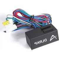


| Product Type | Remote Control |
| Brand | Code Alarm |
| Model | DLRKP |
| Compatibility | Code Alarm vehicle security systems |
| Operating Frequency | 433.92 MHz |
| Number of Buttons | 4 |
| Functions | Lock, Unlock, Panic, Trunk Release |
| Range | Up to 100 meters (open area) |
| Power Source | 3V CR2032 Lithium Coin Battery |
| Battery Life | Approximately 12 months (typical use) |
| Dimensions | 60 x 38 x 14 mm |
| Weight | 28 g (including battery) |
| Material | ABS Plastic |
| Color | Black |
| Operating Temperature | -20°C to 60°C |
| Warranty | 1 year limited |
| Certifications | FCC, IC |
| Water Resistance | Not water-resistant (keep dry) |
| Programming | Requires dealer or DIY procedure (see manual) |
| Replacement Part Number | DLRKP |
Frequently Asked Questions - DLRKP Code Alarm
User questions about DLRKP Code Alarm
0 question about this device. Answer the ones you know or ask your own.
Ask a new question about this device
Download the instructions for your Remote control in PDF format for free! Find your manual DLRKP - Code Alarm and take your electronic device back in hand. On this page are published all the documents necessary for the use of your device. DLRKP by Code Alarm.
USER MANUAL DLRKP Code Alarm
The door lock / unlock outputs are designed to control several different types of systems which may require additional parts. The most common types are shown in the following diagrams.
DLRKP Harness
| 1 | GREEN/BLACK | LOCK MOTOR (30) |
| 2 | WHITE/BLACK | LOCK SWITCH (87A) |
| 3 | VIOLET | LOCK POLARITY (87) |
| 4 | GREEN | LOCK INPUT (-) |
| 5 | RED | BATTERY 12V INPUT (+) |
| 6 | BLUE | UNLOCK INPUT (-) |
| 7 | VIOLET/BLACK | UNLOCK POLARITY (87) |
| 8 | BROWN/BLACK | UNLOCK SWITCH (87A) |
| 9 | BLUE/BLACK | UNLOCK MOTOR (30) |
Negative Switching Locks
All Door Lock and Unlock: Locate the lock / unlock wire at the vehicle's lock / unlock switch.
Verification: These wires will register ground when the Lock and Unlock switches are activated.
Connect the wires shown in the diagram below.
![graph TD A["DLRKP"] --> B["GREEN/BLACK"] A --> C["WHITE/BLACK"] A --> D["VIOLET"] D --> E["GROUND"] A --> F["GREEN"] F --> G["Lock Input (-)"] F --> H["Battery 12V Input (+)"] F --> I["BLUE"] I --> J["Unlock Input (-)"] A --> K["VIOLET/BLACK"] K --> L["BROWN/BLACK"] K --> M["BLUE/BLACK"] L --> N["GR…](/content/2026/07/1501831/images/d524bccccff3cfc92374967547a3c590cabcb821e2ac59368e03cdaab2dca230.jpg)
Positive Switching Locks
All Door Lock and Unlock: Locate the lock / unlock wire at the vehicle's lock / unlock switch.
Verification: These wires will register positive voltage when the Lock and Unlock switches are activated.
Connect the wires shown in the diagram below.
![graph TD A["DLRKP"] --> B["GREEN/BLACK"] A --> C["WHITE/BLACK"] A --> D["VIOLET"] D --> E["Battery 12V"] A --> F["GREEN"] F --> G["Unlock Input (-)"] F --> H["Battery 12V Input (+)"] A --> I["RED"] I --> J["Lock Input (-)"] A --> K["BLUE"] K --> L["Battery 12V"] A --> M["VIOLET/BLACK"] M --> N["Brow…](/content/2026/07/1501831/images/870d7afa55f2960a28fbca4bfbca14693eeac0aa6d4a5d17cdbc3c4387d75e63.jpg)
Reverse Polarity Locks (5-Wire Door locks)
All Door Lock and Unlock: Locate the lock / unlock wire at the vehicle's lock / unlock switch.
Verification: These wires will rest at ground and register positive voltage when the Lock and Unlock switches are activated.
Connect the wires shown in the diagram below.
![graph TD A["DLRKP"] --> B["Reverse Polarity"] B --> C["CUT X"] C --> D["Vehicle Door Lock Motors"] A --> E["GREEN/BLACK"] A --> F["WHITE/BLACK"] A --> G["VIOLET"] G --> H["Battery 12V"] A --> I["GREEN Lock Input (-)"] A --> J["RED Battery 12V Input (+)"] A --> K["BLUE Unlock Input (-)"] A --> L["VIO…](/content/2026/07/1501831/images/6f8c3075a72fcf1238242f9f1212482c2326f17f33b3a877c3975e8cef1a2e80.jpg)
Negative Multiplexed Locks
All Door Lock and Unlock: Locate the lock / unlock wire at the vehicle's lock / unlock switch.
Verification: This wire will show variable ground when the switch is activated. Please consult the wire and location chart for specific resistor values for your vehicle.
Connect the wires shown in the diagram below.
![graph TD A["DLRKP"] --> B["GREEN/BLACK"] A --> C["WHITE/BLACK"] A --> D["VIOLET"] A --> E["GREEN"] A --> F["RED"] A --> G["BLE"] A --> H["VIOLET/BLACK"] A --> I["BROWN/BLACK"] A --> J["BLUE/BLACK"] B --> K["Resistor"] C --> K D --> K E --> L["Ground"] F --> M["Resistor"] G --> N["Ground"] H --> O["R…](/content/2026/07/1501831/images/16f1e4ad06691ebc5a7e56ee603ba1840f828a91d5732de04c5844bcdd621354.jpg)
Positive Multiplexed Locks
All Door Lock and Unlock: Locate the lock / unlock wire at the vehicle's lock / unlock switch.
Verification: This wire will show variable positive voltage when the switch is activated. Please consult the wire and location chart for specific resistor values for your vehicle.
Connect the wires shown in the diagram below.
![graph TD A["DLRKP"] --> B["GREEN/BLACK"] A --> C["WHITE/BLACK"] A --> D["VIOLET"] A --> E["GREEN"] A --> F["RED"] A --> G["BLE"] A --> H["VIOLET/BLACK"] A --> I["BROWN/BLACK"] A --> J["BLUE/BLACK"] B --> K["Resistor"] C --> K D --> K E --> K F --> L["Resistor"] G --> L H --> L I --> L J --> L K -->…](/content/2026/07/1501831/images/cb3da73a6b350572af08663ee442d1c76c776f80d861add9733f83524cf172a5.jpg)
Adding Aftermarket Actuators
After installing aftermarket actuators, (not supplied). Connect the wires shown in the diagram below.
Aftemarket Actuator
![graph LR A["DLRKP"] --> B["GREEN/BLACK"] A --> C["WHITE/BLACK"] A --> D["VIOLET"] A --> E["GREEN Lock Input (-)"] A --> F["RED Battery 12V Input (+)"] A --> G["BLUE Unlock Input (-)"] A --> H["VIOLET/BLACK"] A --> I["BROWN/BLACK"] A --> J["BLUE/BLACK"] B --> K["Ground"] C --> L["Battery 12V"] D -->…](/content/2026/07/1501831/images/c8cf3a090f6b67db74eeff45b409e4ad366b510f937f3ac95bc5cd8deadee1ca.jpg)
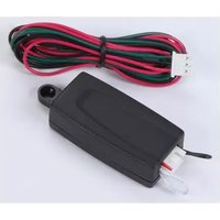


Brand : Code Alarm
Model : DLRKP
Category : Remote control