
BOG9822E00X - Cooker GORENJE - Free user manual and instructions
Find the device manual for free BOG9822E00X GORENJE in PDF.
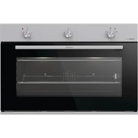


| Product Type | Freestanding Cooker |
| Brand | Gorenje |
| Model | BOG9822E00X |
| Energy Source | Electric |
| Oven Capacity | 70 L |
| Hob Type | Ceramic Glass |
| Number of Cooking Zones | 4 |
| Dimensions (W x D x H) | 600 x 600 x 850 mm |
| Weight | 62 kg |
| Power Consumption | 10.5 kW |
| Oven Functions | Fan-assisted, Grill, Static, Bottom Heat |
| Timer | Yes, digital |
| Child Lock | Yes |
| Automatic Shut-off | Yes |
| Cleaning Method | Enamel with Easy Clean coating |
| Energy Efficiency Class | A |
| Warranty | 2 years |
| Included Accessories | Oven tray, Grill rack |
Frequently Asked Questions - BOG9822E00X GORENJE
User questions about BOG9822E00X GORENJE
0 question about this device. Answer the ones you know or ask your own.
Ask a new question about this device
Download the instructions for your Cooker in PDF format for free! Find your manual BOG9822E00X - GORENJE and take your electronic device back in hand. On this page are published all the documents necessary for the use of your device. BOG9822E00X by GORENJE.
USER MANUAL BOG9822E00X GORENJE
Instructions for use....3
We would like to thank you and congratulate you on your choice.
!! IMPORTANT !!
The appliance must be connected by qualified technician in accordance with the applicable regulations. The data plate (a) of the oven is still visible after the appliance has been installed. This plate, which is visible when the oven door is open, contains all the identification data of the appliance, as well the type of gas and service pressure for which it has been calibrated. Follow the instructions and suggestions carefully to ensure the safe and proper use of this product.
THIS APPLIANCE IS CONCEIVED FOR DOMESTIC USE ONLY. THE MANUFACTURER SHALL NOT IN ANY WAY BE HELD RESPONSIBLE FOR WHATEVER INJURIES OR DAMAGES ARE CAUSED BY INCORRECT INSTALLATION OR BY UNSUITABLE, WRONG OR ABSURD USE. THIS APPLIANCE IS NOT INTENDED FOR USE BY PERSONS (INCLUDING CHILDREN) WITH REDUCED PHYSICAL, SENSORY OR MENTAL CAPABILITIES, OR LACK OF EXPERIENCE AND KNOWLEDGE, UNLESS THEY HAVE BEEN GIVEN SUPERVISION OR INSTRUCTION CONCERNING USE OF THE APPLIANCE BY A PERSON RESPONSIBLE FOR THEIR SAFETY. CHILDREN SHOULD BE SUPERVISED TO ENSURE THAT THEY DO NOT PLAY WITH THE APPLIANCE.
CONTENTS
INSTRUCTIONS FOR THE INSTALLER
INSTRUCTIONS FOR INSTALLATION OF THE APPLIANCE
POSITIONING
VENTILATION
GAS CONNECTION
RIGID PIPE CONNECTION
CONVERSION TO A DIFFERENT TYPE OF GAS
NOZZLE TABLE
ADJUSTMENT OF THE MINIMUM SETTING FOLLOWING CONVERSION TO A DIFFERENT
GAS TYPE
FLUSH FITTING
ELECTRICAL CONNECTIONS
INSTRUCTIONS FOR THE USER
INSTRUCTIONS FOR INSTALLATION OF THE APPLIANCE (positioning and ventilation requirements)
The regulations covering the installation, maintenance and operation of gas appliances for domestic use are applicable regulations.
An extract of these regulations appears below. For all indications not covered, refer to the above-mentioned regulations.
POSITIONING:
the products of combustion from cooking appliances must always be discharged into suitable extractor hoods, which must be connected to a chimney, flue or vented directly to outside the building. In situations where it is not possible to install an extractor hood, an electric extractor fan installed in a window or external wall may be used, provided that all requirements of the ventilation regulations are satisfied; the fan should switch on whenever the appliance is in operation.
VENTILATION:
it is essential that the room in which gas appliances are installed is adequately ventilated to ensure that all the appliances receive the required quantity of fresh air for combustion. To ensure an adequate air flow, it may be necessary to create apertures in accordance with the following requirements:
a) with cross-sectional area of 6 cm2 per kW with a minimum cross-sectional area of 100 cm2 (these apertures may also be created by increasing the gap between the bottom of doors and the floor);
b) situated at the bottom of an external wall, preferably opposite the wall on which combustion products are extracted;
c) the positions of the apertures should selected so as to avoid the possibility of their being obstructed and, if made in external walls, they must be protected with grilles, metal meshes, etc. installed on the outside face of the wall.
If an electric extractor fan for the removal of foul air is installed in the room, the apertures provided for air changes must allow a ventilation rate of at least 35 m3/h per kW of power installed.


GAS CONNECTION
The oven is designed to operate with both natural gas (methane) and liquid gas (LPG), and can be easily converted from one type to another following the instructions given in the relative section of this booklet. Connection to the gas supply must be carried out by qualified technicians and in conformance with the requirements.
If the appliance is to operate with gas bottles (LPG), a pressure regulator conforming to the requirements.
RIGID PIPE CONNECTION
Connection to the mains gas supply may be made via a rigid pipe firmly attached to the fitting "G", or via a flexible stainless steel continuous-wall hose, conforming with a maximum length of 2 metres. The fitting "G" and seal "C" are supplied with the appliance, and comply with standards.
Important: Use two wrenches to turn the fitting "G" to the required position. When the fitting is in the desired position, firmly tighten nut "A".
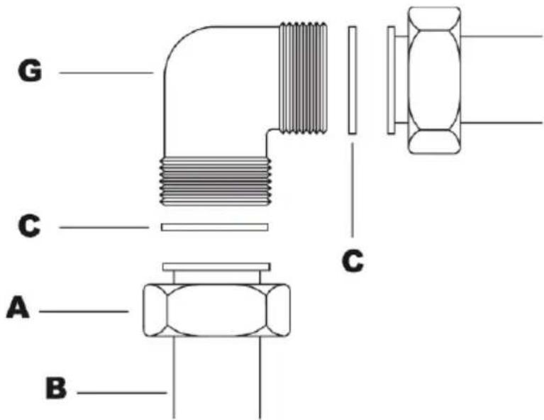
WARNING - IMPORTANT: after connecting the appliance to the gas supply (or to the liquid gas bottles) CHECK FOR LEAKS at the union using a solution of soapy water (never use a naked flame).
CONVERSION TO A DIFFERENT TYPE OF GAS
Before converting the appliance for operation with a different gas type, check which type of gas it is currently set to operate with (adhesive label on appliance). For the correct nozzle diameter, refer to the relative table in this booklet.
Disconnect the electrical power supply to the appliance; For the correct nozzle diameter, refer to the relative table in this booklet.
Replacing the lower burner nozzle
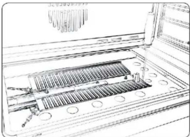
1) Remove the burner cover (see REMOVAL OF THE BURNER COVER PLATE)
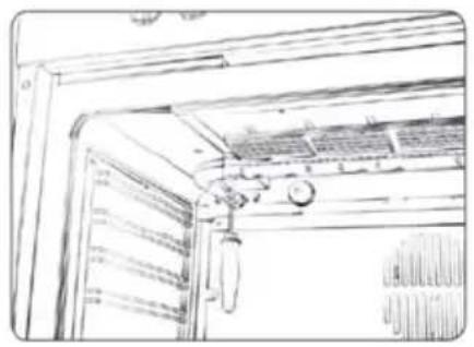
2) Remove the screw securing the oven burner and withdraw the burner from the support together with the heat sensor and the ignition spark plug.
3) Remove the nozzle using a 7 mm box wrench
4) Screw the new nozzle in fully (diameter in hundredths of millimetre stamped on the nozzle), taking care not to cross the thread.
5) Replace the burner reversing the operations in step 2 above.
6) Replace the cover plate.
7) Adjusting the minimum flame.

NOZZLE TABLE
The diameters in hundredths of millimetre are stamped on the nozzle.
| Burner kW | rated load | ∅ Nozzle bore in mm | ||
| G2020 mbar | G3050 mbar | G3029 mbar | ||
| Oven burner | 3,40 | 1,30 | 0,76 | 0,88 |
| Grill burner | 2,80 | 1,18 | 0,72 | 0,83 |
ADJUSTMENTS OF THE MINIMUM SETTING FOLLOWING CONVERSION TO A DIFFERENT GAS TYPE:
Proceed to disassemble the front panel:
- for the front panel, unscrew the two rear fixing screws
- for glass fronts, unscrew the two lock rings under the knob.
Conversion from natural gas to liquid gas
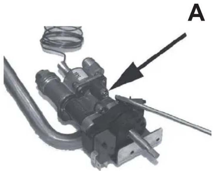
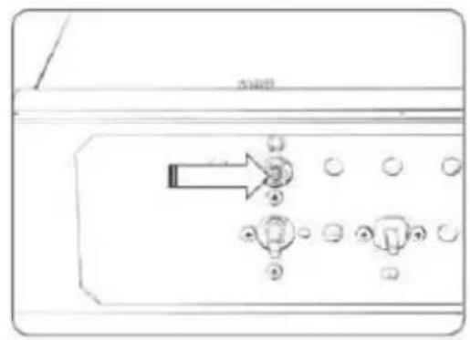
After removing the front panel, insert the screwdriver in the hole in the front wall of the instrument panel and turn regulation screw A clockwise.
Conversion from liquid gas to natural gas
After removing the front panel, light the over with thermostat set to 250° C for at least 10-15 minutes. Then, turn the thermostat to the minimum position. Then turn the bypass screw A counterclockwise until you see a reduced by stable flame. Check that the flame does not go out when the door of the oven is opened and closed repeatedly. If the flame goes out, slight increase the minimum regulation setting.
After converting the appliance to a different type of gas, remember to change the data plate to one with the new data (gas type and pressure).


REPLACING THE GAS GRILL NOZZLE
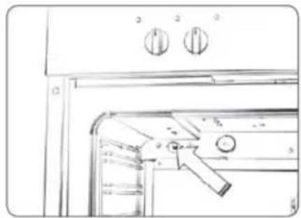
1) Remove the burner screw located at the top front of the oven cavity.
2) Remove the burner together with its heat elements.
3) Remove the nozzle using the 7 mm socket wrench.
4) Fully tighten the new nozzle which must be of the diameter indicated in the table.
5) Put back the burner and secure it with the screw.
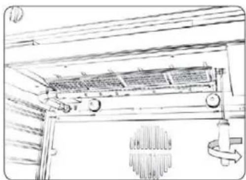


FLUSH FITTING
The oven can be installed under a work top or in a cooking column. The dimensions of the housing for the oven are given in the picture.
Make sure that surrounding materials are heat resistant. Align the oven centrally with respect to the side walls of the units surrounding it and fix it in place with the screws and Allen screws provided.

ELECTRICAL CONNECTIONS
Before connecting the oven to the mains power supply, make sure that:
- The supply voltage corresponds to the specifications on the data plate on the front of the oven.
- The mains supply has an efficient earth (ground) connection complying with all applicable laws and regulations. Correct earthing (grounding) is a legal requirement.
The power cable should never reach a temperature 50° C above ambient temperature at any point along its length. If a fixed appliance is not provided with a power cable and plug, or some other device permitting it to be disconnected from the mains electricity supply, with a gap between the contacts big enough to guarantee class III overvoltage protection, then such a device must be fitted to the power supply in compliance with the regulations governing electrical installations.
The socket or switch must be easily reachable with the oven fully installed.
N.B. The manufacturer declines all responsibility for damage or injury if the above instructions and normal safety precautions are not respected.

INSTRUCTIONS FOR THE USER
Clean the oven thoroughly with soapy water and rinse well. To remove the lateral frames from smooth-walled ovens, proceed as shown in the picture. Operate the oven for about 20 minutes at maximum temperature to burn off all traces of grease which might otherwise create unpleasant smells when cooking.

Important:
As a safety precaution, before cleaning the oven, always disconnect the plug from the power socket or the power cable from the oven. Do not use acid or alkaline substances to clean the oven (lemon juice, vinegar, salt, tomatoes etc.). Do not use chlorine based products, acids or abrasive products to clean the painted surfaces of the oven.
SELF-CLEANING CATALYTIC PANELS
Our smooth walled ovens can be fitted with selfcleaning panels to cover the inside walls.
These special panels are simply hooked on to the walls before the side frames are fitted. They are coated in a special, micro-porous catalytic enamel which oxidises and gradually vaporises splashes of grease and oil at cooking temperatures above 200° C.
If the oven is not clean after cooking fatty foods, operate the empty oven for 60 minutes (max.) at maximum temperature. Never wash or clean selfcleaning panels with abrasive, acid, or alkaline products.

DESCRIPTION OF THE FRONT CONTROL PANEL GAS OVEN WITH ELECTRIC GRILL CONTROLS
- Gas oven temperature control
- Grill, spit roaster and oven light knob
- Gas oven indicator light
- Mechanical timer
- Grill indicator light
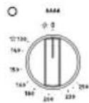


The temperature control knob serves to set the desired oven temperature and is equipped with a safety valve. When the oven is in operation the green light is illuminated.
The minimum position corresponds to an oven temperature of about 130° C. The control knob has stop in the minimum position.
The “max” position corresponds to an oven temperature of 250° C, and is obtained when the knob is turned fully anticlockwise. To light the burner, push in the temperature control knob and turn it anticlockwise to the desired temperature.
Hold the knob pressed in for 5-10 seconds. The burner will be ignited electrically, and the safety valve temperature sensor will heat up thereby allowing gas to continue to flow to the burner.
Do not operate the ignition for longer than 15 seconds. If the burner fails to ignite, leave the door open for at least one minute, then try again.
If the electrical ignition fails to produce a spark, hold a lit taper or match near the burner inspection hole and press and hold the temperature control knob in the "max" position for 5 to 10 seconds.
ELECTRIC GRILL

Infrared grill: equipped with an energy regulator. The heat intensity of the grill can be set from 1 to MAX using the relative control knob. When the grill is in operation, the grill indicator light and the oven interior light will be illuminated. To operate the spit roaster motor, turn the knob to the symbol until you feel a click. Then turn the knob to desired power setting from 0 to 8.
WARNING: The grill will not operate when the oven is on.
MECHANICAL MINUTE TIMER
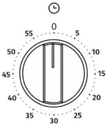
The minute timer can be set to a maximum time of 60 minutes; it emits an alarm tone when the set time period has elapsed. The minute timer operates independently of the oven. The timer knob must first be turned clockwise to the 60 minute position and then turned anti-clockwise to the desired time setting. When the set time has elapsed, the alarm will sound. The alarm tone will stop automatically after a certain period.
DESCRIPTION OF THE FRONT CONTROL PANEL GAS OVEN WITH GAS GRILL CONTROLS
- Lower burner and gas grill temperature control knob
- Oven and spit roaster control knob light
- Gas oven indicator light
- Mechanical timer
- Electrical indicator light
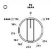


The temperature control knob serves to set the desired oven temperature and is equipped with a safety valve. When the oven is in operation the green light is illuminated.
To turn on the bottom burner, push in the temperature control knob and turn it anticlockwise to the desired temperature.
The minimum position corresponds to an oven temperature of 130° C. The control knob has stop in the minimum position.
The maximum position corresponds to an oven temperature of 250° C, and is obtained when the knob is turned fully anticlockwise.
Hold the knob pressed in for 5-10 seconds. The burner will be ignited electrically, and the safety valve temperature sensor will heat up thereby allowing gas to continue to flow to the burner.
GAS GRILL
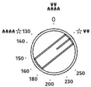
To turn on the grill, turn the knob clockwise to the position ✦ and hold it pressed in for 5-10 seconds.
This knob is used to switch on the oven interior light and the spit roaster (on models so equipped).
VENTILATED VERSION

Our 90cm gas ovens, the first of their kind, also have the various functions in the ventilated version. By turning on the ventilator alone, cold air (room temperature) circulates inside the oven thus helping to rapidly thaw frozen foods. The ventilator function turned on together with the strong heat coming from the bottom burner makes it possible to cook foods more evenly and delicately than with the bottom burner alone. Cooking is faster than in a traditional oven. The system is suitable for cooking foods of different types (fish, meat etc) on a number of levels. Pre-heating is not needed with this function, but for cakes it is in any case preferable.
DEFROSTING


By selecting one of the fan cooking functions and setting the thermostat to zero, the fan allows cold air to circulate inside the oven. In this way frozen food can be rapidly defrosted.
VENTILATED ELECTRIC GRILL

Double top heating element with fan (large area grill). Thermostat setting from 1 to max.
Gas grill with ventilator (can also be used with door shut)
GRILL COOKING

Use the grill to grill or brown foods. Some ovens may be equipped with an electric motor, spit and skewers for turning on the spit. Place the shelf with the food to be cooked in the 1st or 2nd position from the top. Pre-heat the oven for 5 minutes. Turn the thermostat to a temperature between 1 and MAX.
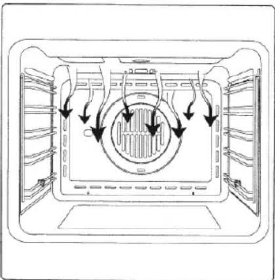
COOLING FAN
The fan is positioned on the upper part of the oven and create a circle of cooling air on the inside of the furni-ture and through the door of the oven.
It starts working when the oven is turned on and stops when the temperature is lowered. After the oven has been running at 200° C, the fan stops after about 30 minutes.
COOKING IN THE OVEN
With this cooking method, you can operate the oven in the normal way and follow the instructions in recipe books. The food to be cooked should preferably be placed on the middle shelf of the oven.
| MAIN COURSE | TEMPERATURE (C) | COOKING TIME (min) | PREHEAT |
| GENOESE SPONGE(SWISS ROLL) | 210 | 15-20 | yes |
| SHORT PASTRY (BISCUITS) | 200 | 10-12 | yes |
| DOUGH WITH RAISING AGENT | 200 | 25-30 | yes |
| SPONGE CAKE(SMALL PAPER PASTRY CASES) | 190 | 20-25 | yes |
| LEAVENED DOUGH (STRUDEL) | 180 | 40-50 | yes |
| PUFF PASTRY (TARTLETS) | 190 | 20-30 | yes |
| SOUFFLÉ | 180 | 35-40 | yes |
| SACHERTORTE | 180 | 55-60 | yes |
| FRUIT PIE | 160 | 160-180 | yes |
| CHOUX PASTRY | 200 | 35-40 | yes |
| ROAST BEEF (APPROX. 1.5 KG) | 200 | 90-120 | yes |
| ROAST PORK (APPROX. 1.5 KG) | 200 | 100-120 | yes |
| PIZZA | 200 | 20-25 | yes |
| BAKED FISH | 180 | 50-60 | yes |
| BAKED VEGETABLES | 170 | 30-40 | yes |
| POULTRY | 190-200 | 60-70 | yes |
Guideline values for cooking with the grill:
| MAIN COURSE | POSITION | COOKING TIME (min) | PREHEAT |
| STEAKS | 10 | 10-15 | - |
| CUTLET | 10 | 15-25 | - |
REMOVAL OF THE BURNER COVER PLATE:
The burner cover plate is secured at the front by two tabs inserted in two slots; to remove the cover plate, raise the rear of the plate so that it pivots at the front and withdraw the tabs form the slots.
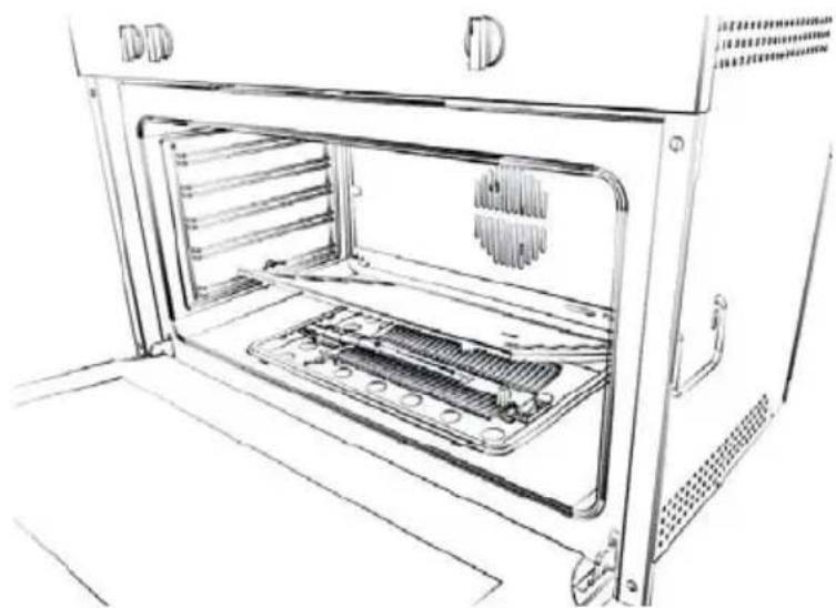
REPLACING THE OVEN LIGHT
IMPORTANT:
The oven light must have these precise features:
a) it must be able to resist high temperatures (up to 300°C)
b) power supply: see V/Hz indicated on data plate.
c) power 25W.
d) E 14 connection.
Before proceeding, disconnect the appliance from the main electricity supply.
- to prevent damage, place a tea cloth in the oven
- unscrew the glass cover of the light
- unscrew the old light bulb and replace it with the new one
- put back the glass cover and remove the tea cloth
- connect the appliance to the main electricity supply

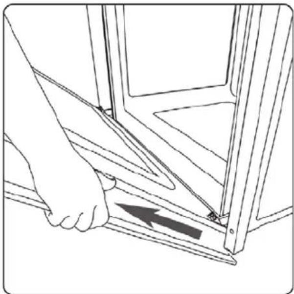
REMOVING THE OVEN DOOR
The oven door can be removed quickly and easily.
To do so, proceed as follows:
- Open the door fully.
- Lift the two levers shown in picture.
- Close the door as far as the first stop (caused by the raised levers).
- Lift the door upwards and outwards to remove it from its mountings.
To replace fit the door, fit the hinges in their mountings and lower the two levers.

RESPECT FOR THE ENVIRONMENT

The documentation provided with this oven has been printed on chlorine free bleached paper or recycled paper to show respect for the environment.
The packaging has also been designed to avoid environmental impact. Packaging material is ecological and can be re-used or recycled. By recycling the packaging, you will help save raw materials as well as reducing the bulk of domestic and industrial waste.
| TECHNICAL FEATURES | ||
| SIZE | Length (mm) - 895 | CAVITY VOLUME |
| Height (mm) - 594 | GAS/GAS - 81 L | |
| Depth (mm) - 572 | GAS/ELECTRIC - 91 L | |

The manufacturer declines all responsibility for possible inaccuracies contained in this pamphlet, due to printing or copying errors. We reserve the right to make on our own products those changes to be considered necessary or useful, without jeopardizing the essential characteristics.
عربي
فرن الغاز
الوضعية:
تحذیر هام:

جدول مقابيس الفوهات


ملائمة التدفق:
تعليمات للمستخدم
ملاحظة مهمة:
وصف لوحة التحكمARGE
مروحة التبريد
إزالة باب الفREN


اتصال گاز

gcd NAZL



تراز کردن
اتصالات برقى
فن خنى كننده
تعويض لمپ فر
: ρρο
خارج کردن درب فر

hfظ محيط زیست
- IMPORTANT
- CONTENTS
- INSTRUCTIONS FOR THE INSTALLER
- INSTRUCTIONS FOR THE USER
- INSTRUCTIONS FOR INSTALLATION OF THE APPLIANCE (POSITIONING AND VENTILATION REQUIREMENTS)
- POSITIONING
- VENTILATION
- GAS CONNECTION
- RIGID PIPE CONNECTION
- CONVERSION TO A DIFFERENT TYPE OF GAS
- REPLACING THE LOWER BURNER NOZZLE
- NOZZLE TABLE
- ADJUSTMENTS OF THE MINIMUM SETTING FOLLOWING CONVERSION TO A DIFFERENT GAS TYPE
- CONVERSION FROM NATURAL GAS TO LIQUID GAS
- CONVERSION FROM LIQUID GAS TO NATURAL GAS
- REPLACING THE GAS GRILL NOZZLE
- FLUSH FITTING
- ELECTRICAL CONNECTIONS
- SELF-CLEANING CATALYTIC PANELS
- DESCRIPTION OF THE FRONT CONTROL PANEL GAS OVEN WITH ELECTRIC GRILL CONTROLS
- ELECTRIC GRILL
- MECHANICAL MINUTE TIMER
- DESCRIPTION OF THE FRONT CONTROL PANEL GAS OVEN WITH GAS GRILL CONTROLS
- GAS GRILL
- VENTILATED VERSION
- DEFROSTING
- VENTILATED ELECTRIC GRILL
- GRILL COOKING
- COOLING FAN
- COOKING IN THE OVEN
- REMOVAL OF THE BURNER COVER PLATE
- REPLACING THE OVEN LIGHT
- REMOVING THE OVEN DOOR
- RESPECT FOR THE ENVIRONMENT
- الوضعية
- وصف لوحة التحكمARGE
Brand : GORENJE
Model : BOG9822E00X
Category : Cooker