
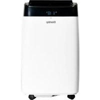
DVAC080B1WDB - Air conditioner DANBY - Free user manual and instructions
Find the device manual for free DVAC080B1WDB DANBY in PDF.
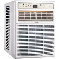


| Product type | Portable air conditioner |
| Brand | Danby |
| Model | DVAC080B1WDB |
| Cooling capacity | 8 000 BTU/h |
| Recommended area | Up to 20 m² |
| Dimensions (L x H x D) | 45 cm x 70 cm x 35 cm |
| Weight | 28 kg |
| Power supply | 115 V ~ 60 Hz, 10 A |
| Power consumption | Approximately 900 W |
| Main functions | Cooling, dehumidification, ventilation |
| Fan speeds | 3 speeds (low, medium, high) |
| Programmable timer | Yes, up to 24 hours |
| Remote control | Yes, included |
| Air filter | Washable and reusable |
| Maintenance and cleaning | Clean the filter every 2 weeks; clean the drain pan regularly |
| Noise level | Approximately 52 dB |
| Safety | Automatic shut-off in case of overheating; compressor protection |
| Spare parts available | Filter, remote control, exhaust kit |
| Refrigerant type | R-32 |
| Color | White |
Frequently Asked Questions - DVAC080B1WDB DANBY
User questions about DVAC080B1WDB DANBY
0 question about this device. Answer the ones you know or ask your own.
Ask a new question about this device
Download the instructions for your Air conditioner in PDF format for free! Find your manual DVAC080B1WDB - DANBY and take your electronic device back in hand. On this page are published all the documents necessary for the use of your device. DVAC080B1WDB by DANBY.
USER MANUAL DVAC080B1WDB DANBY
Do the right thing.*
VERTICAL AIR CONDITIONER
Owner's Manual....1 - 15
VERTICAL AIR CONDITIONER
Danby Products Limited, Guelph, Ontario, Canada N1H 6Z9
Danby Products Inc. Findlay, Ohio, U.S.A. 45840
www.Danby.com

*Trademark of Danby Products * Marque de commerce de Danby Products * Marca comerciales de Danby Products
2023.01.18
Printed in China
Printed in China
Printed in China
Welcome to the Danby family.
We are proud of our quality products and we believe in dependable service. We suggest that you read this owner's manual before plugging in your new appliance as it contains important operation information, safety information, troubleshooting, and maintenance tips to ensure the reliability and longevity of your appliance.
You are entitled to the warranty coverage as described in the owner's manual provided with your new appliance.
- Please write down your appliance information below. You must keep the original proof of purchase receipt to validate and receive warranty services.
- Register your product online and receive a FREE 2 MONTH WARRANTY EXTENSION after filling out a product survey, at www.danby.com/support/product-registration/
Model Number:
Serial Number:
Date of Purchase:
Need Help?
- Read your Owner's Manual for installation help, troubleshooting, and maintenance assistance.
- Visit www.Danby.com to access self-service tools, FAQs and much more by searching your model number in the search bar.
- For the Quickest Customer Service, please fill out the web form at www.danby.com/support. Your submission will go directly to an expert on your particular appliance. Our average response times are between 20 minutes and 2 hours, during EST business hours.
- Call 1-800-263-2629 - please note that during peak hours, hold times can exceed one hour.

Important Safety Information READ AND FOLLOW ALL SAFETY INSTRUCTIONS
SAFETY REQUIREMENTS
This appliance is not intended for use by persons (including children) whose physical, sensory or mental capabilities may be different or reduced, or who lack experience or knowledge, unless such persons receive supervision or training to operate the appliance by a person responsible for their safety.
Children should be supervised to ensure that they do not play with the appliance.
To avoid risk of electric shock, do not operate this appliance in an area that is likely to accumulate standing water. If this condition develops, disconnect the power supply before stepping into the water.
Do not store or use combustible materials such as gasoline or other flammable vapors or liquids in the vicinity of this or any other appliance.
Do not insert fingers or other objects into grills or openings in the appliance.
Do not cover or block the intake and exhaust openings.
Do not operate the appliance without the filter installed.
Do not operate the appliance near heat sources.
This appliance is intended for indoor, residential applications only. Do not use this appliance outdoors. Do not use this appliance for commercial or industrial applications.
If the air conditioner is transported on its back or side, it must be allowed to stand upright for 6 hours before plugging in to avoid damage to internal components.
GROUNDING INSTRUCTIONS
This appliance must be grounded. Grounding reduces the risk of electrical shock by providing an escape wire for the electrical current.
This appliance has a cord that has a grounding wire with a 3-prong plug. The power cord must be plugged into an outlet that is properly grounded. If the outlet is a 2-prong wall outlet, it must be replaced with a properly grounded 3-prong wall outlet. The serial rating plate indicates the voltage and frequency the appliance is designed for.
WARNING - Improper use of the grounding plug can result in a risk of electric shock. Consult a qualified electrician or service agent if the grounding instructions are not completely understood, or if doubt exists as to whether the appliance is properly grounded.
Do not connect the appliance to extension cords, adapters or together with another appliance in the same wall outlet.
Do not splice the power cord. Do not under any circumstances cut or remove the third ground prong from the power cord.
If the power supply cord is damaged, it must be replaced by the manufacturer, its service agent or similar qualified person in order to avoid hazard.
Receptacle wiring should be a minimum of 14 gauge. Use copper wire only.
A time delay fuse or time delay circuit breaker is required. A separate circuit, serving only this appliance, must be provided.
INSTALLATION INSTRUCTIONS
PREPARATION
For wood frame casement windows: It may be necessary to construct a frame using at least 1 inch thick wood with a 15.5 inch wide opening.
For brick or cement building construction: It may be necessary to put a wood strip under the appliance for mounting purposes.
REQUIRED TOOLS
- Flat head screwdriver
- Phillips head screwdriver
- Carpenter's level
- Tape measure
- Fine tooth saw
- Electric or hand drill
LOCATION
When deciding on an installation location, ensure the window is within 6 feet of an electrical outlet and choose a window that has the below dimensions:
• 15.4 inches (39 cm) width • 20.9 inches (53 cm) minimum height • 39.6 inches (100.5 cm) maximum height
Note: Height measurements must be of a clear opening above a mounting platform. In some cases the above dimensions may vary slightly. If necessary, installation can be completed by adding window jambs.
ACCESSORIES
- Platform
- Support brace
- Adjustment bolt
- Hex flange nut
- Track seal
- Side channel seal
- Foam seal strip/Sash seal
- Safety bracket
- 2 1/2" screw (x2)
- 1 3/4" screw (x2)
- 1" screw (x2)
- 3/4" screw (x6)
- 3/4" self threading screw (x7)
- Window locking bracket
- Plastic window panel
- Side channel (x2)
- 3/8" screw (x6)
- Panel frame/Seal assembly

INSTALLATION INSTRUCTIONS
INSTALLATION IN A SLIDING WINDOW
1. Attach the support brace to the platform.
Use the adjustment bolt and hex flange nut to complete the assembly. Choose the slot and adjustment bolt hole that will create a 45 degree angle between the platform and the support brace. Hold the assembled platform in the chosen window location to ensure the assembly will rest properly and allow for a 3/16" slope to the outside. If you are planning to use a siding protection board (see Step 5) hold the board in place to test the platform assembly configuration.
2. Measure and mark the window sill.
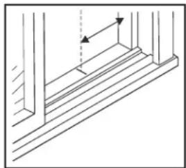
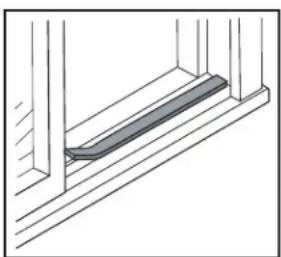
Measure 8 11/16" from the window jamb and mark a line on the window sill. This mark will help to center the support platform in the window. If any sash stop protrudes more than 1 inch from the side window jambs, the measurement should be increased accordingly. Screen and storm window frames may also require adjustments to the measurement.
3. Make screw holes for the platform.
Center the platform assembly on the line marked in the previous step with the inside platform tab pressed against the inside edge of the window track. Using the holes on the platform as a guide, mark and drill two 9/64" diameter holes. Drill holes in either track or stool.
Caution: Ensure the wood stool or window track is securely attached to the building construction. Use longer screws to reach the sub-framing if necessary.
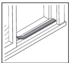
4. Add the foam track seal.
Remove the protective backing from the foam track seal. Apply the seal to the room side of the window track. The center of the foam seal should coincide with the line marked in Step 2. The two screw holes drilled in Step 3 should be directly above the foam seal in the inner track.


INSTALLATION INSTRUCTIONS
INSTALLATION IN A SLIDING WINDOW
5. Add a siding protection board.
A siding protection board can be used to protect the house siding from damage. The board should be long enough to span two wall studs.
Adjust the platform assembly so that the air conditioner will be 1" to 1 1/4" lower in the back, tilted approximately 3° to 4° downward to the outside. This allows condensation that forms inside the appliance during normal use to drain to the outside.
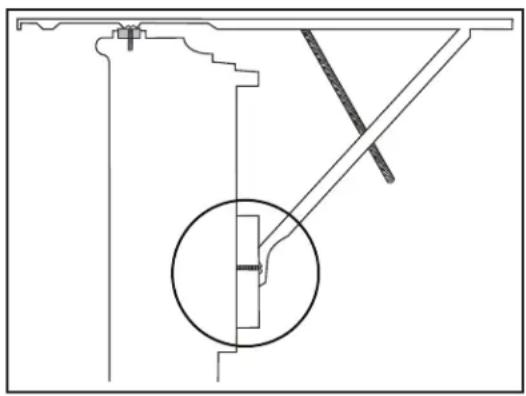
6. Install the platform assembly.
Place the platform assembly in the window with the platform tab against the inside of the window track and attach it to the window jamb using the provided screws.
Ensure that the platform assembly is tilted 1" to 1 1/4" (3° to 4°) downward to the outside.
Ensure that the platform assembly is level from side to side. Make sure the window track is level. Use leveling shims as necessary to ensure the appliance is level.
7. Cut the plastic window panel.
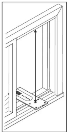
Measure the height of the window opening from the top of the platform assembly to the top of the window opening. Subtract 20 5/8" to account for the size of the air conditioner and mark the measurement on the plastic window panel along the longer side. Cut the panel to the correct size and remove any burrs with a file.


INSTALLATION INSTRUCTIONS
INSTALLATION IN A SLIDING WINDOW
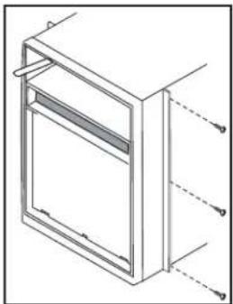
8. Attach the side channels.
Fasten the side channels to the sides of the air conditioner using the provided screws. Make sure the hook ends of the channels face the rear of the appliance.
9. Assemble the window panel and frame
Slide the plastic window panel into the panel frame with the smooth side facing the room. Slide the panel frame assembly into the side channels of the air conditioner cabinet. Make sure the plastic window panel is firmly enclosed on all sides by the retainer grooves.
10. Add the weather stripping.
Cut the side channel foam seal into two equal lengths. Remove the protective backing and apply it to the rear side of the cabinet side channels, starting just below the panel frame assembly. Cut off any excess length so the seal is even with the bottom of the cabinet side channel.
11. Remove the front panel.
Remove the two front retaining screws from the front frame. Pull the front out and lift up to release the front cover from the cabinet. Release the coupler plugs. Removing the front panel will allow you to install the safety bracket in step 13.


INSTALLATION INSTRUCTIONS
INSTALLATION IN A SLIDING WINDOW
12. Install the air conditioner.
Place the air conditioner in the window opening. It should sit on the platform assembly so that the window panel frame and cabinet side channels are against the top and side window jambs.
Slide the inner window sash firmly against the side of the cabinet. Make sure not to peel off the side channel or window track foam seals. If the panel frame does not fit snugly against the inner window sash, secure the panel frame to the sash with 3/4" screws or 3/4" self threading screws. Use the partially plugged holes in the panel frame. Drill 1/8" pilot holes for the screws.
13. Install the safety bracket.
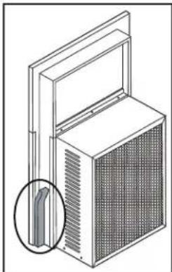
Hook the safety bracket over the base of the cabinet and fasten it to the front of the platform assembly with a 3/4" self threading screw. The safety bracket prevents movement of the air conditioner after completing the installation.
14. Install the sash foam and window lock.
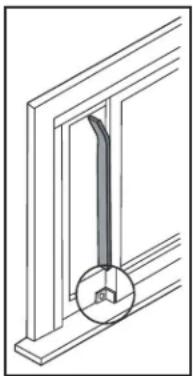
Insert the foam sash seal between the vertical sash and the window glass. Use the window locking bracket to lock the inner window sash to the base of the outer window sash. Use 3/4" screw or 3/4" self threading screw.
15. Replace the front cover.
Reconnect the coupler plugs and ensure that the exhaust control is positioned through the front cover in the correct location. Replace the retaining screws on the sides of the cabinet that hold the front cover in place.


INSTALLATION INSTRUCTIONS
INSTALLATION IN A CASEMENT WINDOW
If you are installing the air conditioner in a casement window, follow the above steps for a sliding window but keep the following points in mind:
- Open the window the maximum amount to allow for clearance of the cabinet.
- The crank handle should be removed to allow the platform assembly to be fastened to the window jamb.
- If the window cannot open far enough for the cabinet to clear the window, (more than 15 1/2") remove the window entirely by drilling out the rivets. Bolts can service as the pivots in future.
- To avoid the crank handle and window clearance problems, install the appliance in a stationary sash section. The horizontal mullion and the two glass panels must be removed before installation.
ALTERNATE WINDOW JAMB APPLICATIONS
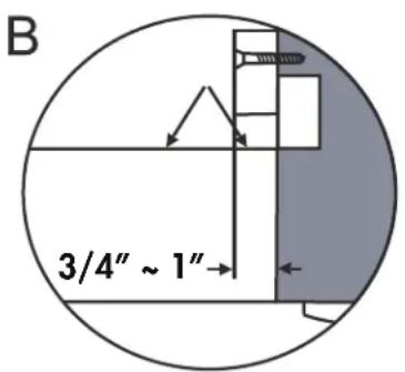
To install the air conditioner in windows that do not have flanges or wood stops on the top and side jambs, the channels and panel frame must fit against a mating flange (or 1/16" maximum thick angle) attached to the window jambs.
Figure A shows this angle installed.
Figures B and C show alternate treatments.
On the sash side of the opening the leading corner of the inner sash becomes the flange. You can purchase the angle strip locally.


OPERATING INSTRUCTIONS
CONTROL PANEL
1. Exhaust Control:
- In the Closed position, the air conditioner will circulate inside air only. Use the Closed position when maximum cooling is desired or for air circulation when the appliance is set to fan mode.
- In the Open position, the air conditioner will exhaust air to the outside. Use the Open position to remove stale air from the room and exhaust it to the outside and to draw fresh air into the home.
- Mode Button: Used to choose the operating mode.
3. Energy Saver Button:
- The Energy Saver Function will automatically cycle the fan on and off when the compressor is not in use to minimize how often the compressor needs to turn on. This function is available in Cool, Dry, Auto Cool and Auto Fan modes.
- The fan will continue to run for 3 minutes after the compressor turns off. The fan will then cycle on for 2 minutes in 10 minute intervals until the ambient temperature is above the set temperature, at which point the compressor will turn on and cooling will resume.
- Timer Button: Used to set the auto on and auto off timer.
5. Up and Down Arrows:
• Used to adjust the set temperature and the timer function.
- Press and hold the up and down buttons at the same time for 3 seconds to change the temperature display between °F and °C.
- Display Panel: Displays the set temperature, the ambient temperature and the timer settings. To change the temperature scale being displayed, press the up and down buttons at the same time.
7. Sleep Button:
- The Sleep Function can be used to conserve energy during sleeping hours. When selected, the set temperature will increase by 1°C/2°F every half hour for one full hour. The appliance will hold the new set temperature for 6 hours before automatically returning to normal operation.
- Filter Button: The indicator light will illuminate as a reminder to check the filter. Once the filter has been cleaned, use this button to resume operation.
- Fan Button: Used to set the fan speed. The fan can be set to Low, Medium, High and Auto.
- Power Button: Press to turn the appliance on or off.
11. Remote Control Receiver

OPERATING INSTRUCTIONS
REMOTE CONTROL
- Display panel: Displays the set temperature, the ambient temperature and the timer settings. To change the temperature scale being displayed, press the °C/°F button.
- Up and down arrows: Used to adjust the set temperature in 1° increments and the timer function in 30-minute increments up to 10 hours, then in 1-hour increments up to 24 hours.
- Mode button: Used to choose the operating mode.
- Follow me button: Used to set the follow me function.
- °C/°F button: Used to change the temperature scale.
- LED button: Press to turn the LED backlight on or off.
- Power button: Used to turn the appliance on or off.
- Sleep button: Used to set the sleep function.
- Fan button: Used to set the fan speed. The fan can be set to low, medium, high, and auto.
- Timer buttons: Used to set the auto-on and auto-off timers.
- Energy saver button: Used to set the energy saver function.
- Lock button: Press the °C/°F button and the timer button at the same time to lock the remote control and prevent the settings from being inadvertently changed.

REMOTE CONTROL BATTERIES
The remote control requires two AAA alkaline batteries (included). Batteries should be replaced when:
a) No sound is heard when attempting to program the appliance.
b) The appliance does not respond to a command issued by the remote control.
Battery replacement:
- Slide the rear cover on the remote in the direction of the arrow.
- Insert two AAA batteries following the same orientation depicted inside the battery chamber (+/-).
- Reinstall the rear cover.
- If the remote control will not be used for extended periods of time, the batteries should be removed.
Notes:
- Protect the remote control from high temperatures, and keep it away from radiation exposure.
- Keep the control panel receiver out of direct sunlight.
- Do not mix old and new batteries.
- Do not mix alkaline, standard (carbon-zinc), or rechargeable (ni-cad, ni-mh, etc) batteries.
- The remote operates within a range of 8 meters (26 ft.) from the receiver located inside the main appliance. Any obstruction between the receiver and remote may cause signal interference, limiting the ability to program the main unit.
OPERATING INSTRUCTIONS
REMOTE CONTROL REGULATIONS
This Class B digital apparatus complies with the Canadian CAN ICES-003(B)/NMB-003(B) standard.
This equipment has been tested and found to comply with the limits for a Class B digital device, pursuant to Part 15 of the FCC Rules. These limits are designed to provide reasonable protection against harmful interference in a residential installation.
This equipment generates, uses and can radiate radio frequency energy and, if not installed and used in accordance with the instructions, may cause harmful interference to radio communications. However, there is no guarantee that interference will not occur in a particular installation.
If this equipment does cause harmful interference to radio or television reception, which can be determined by turning the equipment off and on, the user is encouraged to try to correct the interference by one or more of the following measures:
- Reorient or relocate the receiving antenna.
- Increase the separation between the equipment and receiver.
- Connect the equipment into an outlet on a circuit different from that to which the receiver is connected.
- Consult the dealer or an experienced radio/TV technician for help.
Changes or modifications not approved by the party responsible for FCC and Industry Canada compliance could void the user's authority to operate the equipment. This appliance complies with Part 15 of the FCC Rules.
Operation is subject to the following conditions:
- This device may not cause harmful interference.
- This device must accept any interference received, including interference that may cause undesired operation.
SUPPLIER'S DECLARATION OF CONFORMITY
47 CFR § 2.1077 Compliance Information
Unique Identifier: Danby, RG51G(1)/CEFU1
Responsible Party U.S. Contact Information:
Danby Products Inc.
1800 Production Drive
Findlay, OH
45840
Telephone number or internet contact information: Danby.com
FCC Compliance Statement: This appliance complies with Part 15 of the FCC Rules. Operation is subject to the following conditions:
- This device may not cause harmful interference.
- This device must accept any interference received, including interference that may cause undesired operation.
OPERATING INSTRUCTIONS
FUNCTION INSTRUCTION
Operating Modes
There are four operating modes to choose from. Press the Mode Button repeatedly to choose the desired mode. The adjacent indicator light will illuminate to show which mode has been selected.
- Cool Mode
Choose Cool Mode to set the cooling function. Use the Up and Down Arrows to choose the desired temperature. When Cool Mode is selected, the fan speed can be adjusted by pressing the fan button.
- Dry Mode
Choose Dry Mode to remove excess moisture from the air during periods of high humidity. All water pulled from the air will condense inside the appliance and drain out the back. The fan speed will be automatically set and cannot be modified in Dry Mode.
- Fan Mode
Choose Fan Mode to run the internal fan without engaging the cooling function. Press the fan button repeatedly to choose the fan speed: Low, Med, High, or Auto.
- Auto Mode
Auto Mode is a pre-set factory program that automatically defines the mode (Cool or Dry) and fan speed based on the set temperature, the ambient temperature, and the ambient humidity.
UP AND DOWN ARROWS
The Up and Down Arrows will modify the set temperature in 1° increments.
The Up and Down Arrows will modify the set time of the timer function in 0.5 hour increments up to 10 hours, and then in 1 hour increments up to 24 hours maximum.
TIMER FUNCTION
The Timer Function can be used to turn the appliance on or off after a set period of time.
Auto On Function
- Press the Timer Button once and the Auto On indicator light will illuminate.
- Use the Up and Down Arrows to select the desired amount of time before the appliance should turn on.
- Use the Mode Button to select the desired mode.
- Use the Fan Button to select the desired fan speed.
- The time selected will appear on the display panel and will count down until the appliance turns on.
Auto Off Function
- Press the Timer Button twice and the Auto Off indicator light will illuminate.
- Use the Up and Down Arrows to select the desired amount of time before the appliance should turn off.
- The time selected will appear on the display panel and will count down until the appliance turns off.
Using Auto On and Auto Off Simultaneously
If there is a need for the appliance to turn on, run for a set period of time and then turn off, the Auto On and Auto Off functions can be used at the same time by first setting one and then the other. Both indicator lights will illuminate and the display will count down to the appliance either turning off or on, whichever function was set first.
Note: The timer will not cycle the appliance on and off indefinitely. The Auto On and Auto Off timers will function one time and then the appliance will return to regular functioning.
Turning the appliance off, pressing the default button on the remote or unplugging the appliance will clear all memory settings, including the timer.
OPERATING INSTRUCTIONS
FOLLOW ME FUNCTION
There is a temperature sensor built into the remote control that will continuously collect the current room temperature. Keep the remote control with you and the appliance will automatically adjust the set temperature based on the current temperature where you are located to reach the most comfortable condition and temperature.
Press the follow me button to activate the follow me function. The remote will display the current temperature at its location. The remote will send a signal to the air conditioner every 3 minutes, so long as you remain within range of the appliance.
The follow me light on the control panel of the appliance will illuminate for 5 seconds every three minutes to indicate that it has received a signal from the remote. If the appliance does not receive a signal from the remote during any 7 minute interval, it will beep to indicate that the follow me mode has ended.
The maximum distance for the follow me feature is 8 meters (26 feet). This feature is available in cool and auto modes.
CARE & MAINTENANCE
AIR FILTER
The check filter light on the control panel will illuminate after 250 hours of operation as a reminder to check the filter. Follow the steps below to clean the filter and return the appliance to normal functioning.
- The air filter is located behind the front intake grill. To remove the air filter, grasp the filter tab on the top of the grill and pull upwards.
- Use a vacuum cleaner with a soft brush attachment to remove any large debris or dust build up from the air filter.
- Wash the filter in lukewarm, soapy water, below 40° C ( 104° F), or use a neutral cleaning agent.
- Rinse the filter with clean water and dry thoroughly before reinstalling in the appliance.
- Press the filter button on the control panel to resume normal functioning.
Note: Do not operate the appliance without the air filter installed.

CARE & MAINTENANCE
CLEANING
To avoid possible electric shock, ensure that the appliance is unplugged before performing any cleaning or maintenance.
The outside of the appliance can be wiped clean with a soft cloth or with a lukewarm, damp cloth if necessary.
Do not use gasoline, benzene, thinner or any other chemicals to clean this appliance as these substances can cause damage to the finish and deformation of plastic parts.
Never pour water directly onto the appliance as this will cause deterioration of electrical components and wiring insulation.
END OF SEASON CARE
Before removing the appliance from service for the year, operate the appliance on high fan mode for half a day to ensure the inside of the appliance is dry. This will help avoid the growth of mold or mildew inside the appliance. Ensure the filter is clean and dry. Store the appliance covered in a dry location.
Note: When installing or removing the appliance from the window, ensure that caution is taken to prevent it from falling backward. It is recommended that installation or removal is completed with assistance to prevent injury to persons or damage to property or the appliance.
DISPOSAL
Check for local regulatory compliance regarding approved and safe disposal of this appliance.
ERROR CODES
AS - Room temperature sensor error

Evaporator temperature sensor error
TROUBLESHOOTING
Appliance will not operate
• Plug is not fully inserted into the wall outlet - Blown fuse or circuit breaker
Insufficient cooling
- Air filters are dirty
- Blocked air flow • Appliance size is too small for application
Noise
- The ground is not level
- Air filters are dirty
- Gurgling sounds are normal; this is the refrigerant moving inside the appliance
Odors
- Formation of mold or mildew on internal wet surfaces
- Place an algaecide tablet in base pan; push the tablet through the grill on the back of the appliance
LIMITED "CARRY IN" WARRANTY
This quality product is warranted to be free from manufacturer's defects in material and workmanship, provided that the unit is used under the normal operating conditions intended by the manufacturer.
This warranty is available only to the person to whom the unit was originally sold by Danby Products Limited (Canada) or Danby Products Inc. (U.S.A.) (hereafter "Danby") or by an authorized distributor of Danby, and is non-transferable.
TERMS OF WARRANTY
Plastic parts are warranted for thirty (30) days from the date of purchase, with no extensions provided.
First 24 months
During the first twenty four (24) months, any functional parts of this product found to be defective, will be repaired or replaced, at warrantor's option, at no charge to the original purchaser.
To obtain service
Contact the dealer where the unit was purchased, or contact the nearest authorized Danby service depot, where service must be performed by a qualified service technician. If service is performed on the unit by anyone other than an authorized service depot, all obligations of Danby under this warranty shall be void.
It is the responsibility of the purchaser to transport the appliance to the nearest authorized service depot.
Transportation charges to and from the service location are not covered by this warranty and are the responsibility of the purchaser.
Nothing in this warranty implies that Danby will be responsible or liable for any spoilage or damage to food or other contents of this appliance, whether due to any defect of the appliance or its use, whether proper or improper.
EXCLUSIONS
Except as provided herein by Danby, there are no other warranties, conditions, representations, or guarantees, express or implied, made or intended by Danby or its authorized distributors, and all other warranties, conditions, representations, or guarantees, including any warranties, conditions, representations, or guarantees under any Sale of Goods Act or similar legislation or statute, are hereby expressly excluded. Except as provided herein, Danby shall not be responsible for any damages to persons or property, including the unit itself, however caused, or any consequential damages arising from the malfunction of the unit. By purchasing the unit, the purchaser agrees to indemnify and hold harmless Danby from any claim for damages to persons or property caused by the unit.
GENERAL PROVISIONS
No warranty or insurance herein contained or set out shall apply when damage or repair is caused by any of the following:
1) Power failure. 2) Damage in transit or when moving the appliance. 3) Improper power supply such as low voltage, defective house wiring, or inadequate fuses. 4) Accident, alteration, abuse, or misuse of the appliance such as inadequate air circulation in the room or abnormal operating conditions (i.e., extremely high or low room temperature). 5) Use for commercial or industrial purposes (i.e., if the appliance is not installed in a domestic residence). 6) Fire, water damage, theft, war, riot, hostility, acts of God such as hurricanes, floods, etc. 7) Service calls resulting in customer education. 8) Improper installation (i.e., building in a free-standing appliance or using an appliance outdoors that is not approved for outdoor application, including but not limited to: garages, patios, porches, or anywhere that is not properly insulated or climate controlled).
Proof of purchase date will be required for warranty claims; retain bills of sale. In the event that warranty service is required, present the proof of purchase to our authorized service depot.
Warranty Service
Carry In
Danby Products Limited
PO Box 1778, Guelph, Ontario, Canada N1H 6Z9
Telephone: (519) 837-0920 FAX: (519) 837-0449
1-800-263-2629
04/17
Danby Products Inc
PO Box 669, Findlay, Ohio, U.S.A. 45840
Telephone: (419) 425-8627 FAX: (419) 425-8629
INSTALLATION INSTRUCTIONS
INSTALLATION IN A SLIDING WINDOW


INSTALLATION INSTRUCTIONS
INSTALLATION IN A SLIDING WINDOW

OPERATING INSTRUCTIONS
INSTALLATION IN A SLIDING WINDOW


OPERATING INSTRUCTIONS
INSTALLATION IN A SLIDING WINDOW


OPERATING INSTRUCTIONS
INSTALLATION IN A CASEMENT WINDOW


OPERATING INSTRUCTIONS
CONTROL PANEL
CARE AND MAINTENANCE
CLEANING
Danby Products Limited
PO Box 1778, Guelph, Ontario, Canada N1H 6Z9




UP AND DOWN ARROWS
Danby Products Limited
PO Box 1778, Guelph, Ontario, Canada N1H 6Z9
Telephone: (519) 837-0920 FAX: (519) 837-0449
1-800-263-2629
04/17
Danby Products Inc.
PO Box 669, Findlay, Ohio, U.S.A. 45840
Telephone: (419) 425-8627 FAX: (419) 425-8629
NOTES / REMARKS / NOTES:
NOTES / REMARKS / NOTES:


- WELCOME TO THE DANBY FAMILY
- NEED HELP
- IMPORTANT SAFETY INFORMATION READ AND FOLLOW ALL SAFETY INSTRUCTIONS
- SAFETY REQUIREMENTS
- GROUNDING INSTRUCTIONS
- INSTALLATION INSTRUCTIONS
- PREPARATION
- REQUIRED TOOLS
- LOCATION
- ACCESSORIES
- INSTALLATION IN A SLIDING WINDOW
- ATTACH THE SUPPORT BRACE TO THE PLATFORM
- MEASURE AND MARK THE WINDOW SILL
- MAKE SCREW HOLES FOR THE PLATFORM
- ADD THE FOAM TRACK SEAL
- ADD A SIDING PROTECTION BOARD
- INSTALL THE PLATFORM ASSEMBLY
- CUT THE PLASTIC WINDOW PANEL
- ATTACH THE SIDE CHANNELS
- ASSEMBLE THE WINDOW PANEL AND FRAME
- ADD THE WEATHER STRIPPING
- REMOVE THE FRONT PANEL
- INSTALL THE AIR CONDITIONER
- INSTALL THE SAFETY BRACKET
- INSTALL THE SASH FOAM AND WINDOW LOCK
- REPLACE THE FRONT COVER
- INSTALLATION IN A CASEMENT WINDOW
- ALTERNATE WINDOW JAMB APPLICATIONS
- OPERATING INSTRUCTIONS
- CONTROL PANEL
- EXHAUST CONTROL
- ENERGY SAVER BUTTON
- UP AND DOWN ARROWS
- SLEEP BUTTON
- REMOTE CONTROL RECEIVER
- REMOTE CONTROL
- REMOTE CONTROL BATTERIES
- BATTERY REPLACEMENT
- NOTES
- REMOTE CONTROL REGULATIONS
- SUPPLIER'S DECLARATION OF CONFORMITY
- FUNCTION INSTRUCTION
- OPERATING MODES
- COOL MODE
- DRY MODE
- FAN MODE
- AUTO MODE
- TIMER FUNCTION
- AUTO ON FUNCTION
- AUTO OFF FUNCTION
- USING AUTO ON AND AUTO OFF SIMULTANEOUSLY
- FOLLOW ME FUNCTION
- CARE & MAINTENANCE
- AIR FILTER
- CLEANING
- END OF SEASON CARE
- DISPOSAL
- ERROR CODES
- TROUBLESHOOTING
- APPLIANCE WILL NOT OPERATE
- INSUFFICIENT COOLING
- NOISE
- ODORS
- LIMITED "CARRY IN" WARRANTY
- TERMS OF WARRANTY
- EXCLUSIONS
- GENERAL PROVISIONS
- CARE AND MAINTENANCE
Brand : DANBY
Model : DVAC080B1WDB
Category : Air conditioner