
FreeSpace ZA 2120-LZA - Receiver BOSE - Free user manual and instructions
Find the device manual for free FreeSpace ZA 2120-LZA BOSE in PDF.


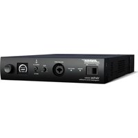
| Product Type | Commercial Zone Amplifier/Receiver |
| Brand | Bose |
| Model | FreeSpace ZA 2120-LZA |
| Dimensions (H x W x D) | 1.75 x 19 x 12 inches (1U rackmount) |
| Weight | Approximately 10 lbs (4.5 kg) |
| Power Supply | AC 100-240V, 50/60 Hz, auto-switching |
| Power Consumption | 200W maximum |
| Amplifier Output Power | 120W per channel (2 channels) into 4 or 8 ohms |
| Inputs | 2 balanced line-level inputs (Euroblock connectors) |
| Outputs | 2 speaker outputs (Euroblock), 1 preamp out (RCA) |
| Frequency Response | 20 Hz – 20 kHz (±1 dB) |
| Signal-to-Noise Ratio | >90 dB |
| THD+N | <0.05% at rated power |
| Cooling | Variable speed fan, front-to-back airflow |
| Protection Features | Short circuit, thermal, overcurrent, DC offset |
| Controls | Volume knobs per channel, power switch, EQ preset dip switches |
| Indicators | Power LED, signal/clip LEDs per channel |
| Mounting | 19" rackmount, 1U height, brackets included |
| Operating Temperature | 0°C to 40°C (32°F to 104°F) |
| Humidity | Non-condensing, up to 90% |
| Certifications | UL, CE, FCC Class B |
| Warranty | 5 years (limited, parts and labor) |
| Cleaning | Wipe with dry cloth; do not use liquids or solvents |
| Spare Parts & Repairability | Contact Bose Professional support for authorized service centers |
| General Information | User manual available for free download at Bose.com |
Frequently Asked Questions - FreeSpace ZA 2120-LZA BOSE
User questions about FreeSpace ZA 2120-LZA BOSE
0 question about this device. Answer the ones you know or ask your own.
Ask a new question about this device
Download the instructions for your Receiver in PDF format for free! Find your manual FreeSpace ZA 2120-LZA - BOSE and take your electronic device back in hand. On this page are published all the documents necessary for the use of your device. FreeSpace ZA 2120-LZA by BOSE.
USER MANUAL FreeSpace ZA 2120-LZA BOSE
FreeSpace® IZA 2120-LZ & IZA 2120-HZ
Integrated Zone Amplifiers
FreeSpace® ZA 2120-LZ & ZA 2120-HZ
Zone Amplifiers
Installation and Operating Guide
Included accessories....20
Limited warranty....20
Front and Rear Panels
FreeSpace® IZA 2120-LZ 21
IZA 2120-LZ front panel....21
IZA 2120-LZ rear panel....22
FreeSpace ® IZA 2120-HZ....23
IZA 2120-HZ front panel 23
IZA 2120-HZ rear panel 24
FreeSpace® ZA 2120-LZ/HZ 25
ZA 2120-LZ/HZ front panel....25
ZA 2120-LZ/HZ rear panel....25
Installation and Placement
Importance of proper ventilation....26
Removing rack-mount ears....26
Placing on a flat surface....26
Installing the feet on the amplifier 27
Stacking units 27
Making Connections
Connecting an amplifier to a ControlSpace® engineered sound processor 28
Page input connections....28
Remote control connections....29
Remote volume and source selection control 29
IZA 2120-HZ remote configuration examples....29
Remote connections to zone amplifiers....31
Remote volume control....31
ZA 2120-HZ remote configuration examples....32
Remote input functionality 32
Mute with standard contact closure 33
Loudspeaker usage....33
Expanding an IZA system with a ZA amplifier
Expansion overview....34
Connecting an IZA 2120-LZ/HZ amplifier to a ZA 2120-LZ/HZ amplifier ....34
Line input connections....34
Connecting an IZA 2120-LZ/HZ amplifier to multiple zone amplifiers ....35
Technical Information
Troubleshooting 36
AC current draw and thermal dissipation information....37
IZA 2120-LZ specifications ....38
IZA 2120-HZ specifications....39
ZA 2120-LZ specifications ....40
ZA 2120-HZ specifications....41
Block Diagrams
Additional Resources
This product is intended for installation by professional installers only! This document is intended to provide professional installers with basic installation and safety guidelines for Bose® FreeSpace® amplifiers in typical fixed-installation systems. Please read this document before attempting installation.

Warning: All Bose products must be used in accordance with local, state, federal and industry regulations. It is the installer's responsibility to ensure installation of the amplifier is performed in accordance with all applicable codes, including local building codes and regulations. Consult the local authority having jurisdiction before installing this product.

Warning: To reduce the risk of fire or electrical shock, do not expose the product to rain or moisture.

Caution: Do not mount the chassis in locations where condensation may occur.

Warning: Do not expose this apparatus to dripping or splashing, and do not place objects filled with liquids such as vases, on or near the apparatus. As with any electronic products, use care not to spill liquids into any part of the system. Liquids can cause a failure and/or a fire hazard.


The lightning flash with arrowhead symbol, within an equilateral triangle, is intended to alert the user to the presence of uninsulated dangerous voltage within the system enclosure that may be of sufficient magnitude to constitute a risk of electrical shock. Do not touch the output terminals while amplifier power is ON. Make all connections with amplifier OFF.

The exclamation point within an equilateral triangle, as marked on the system, is intended to alert the user to the presence of important operating and maintenance instructions in this installation guide.

Caution: This product shall be connected to an AC mains socket outlet with a protective earthing (grounding) connection.

Caution: Do not place any naked flame sources, such as lighted candles, on or near the apparatus.

Caution: Make no modifications to the system or accessories. Unauthorized alterations may compromise safety, regulatory compliance, and system performance.

Warning: Contains small parts which may be a choking hazard. Not suitable for children under age 3.
Note: The product label is located on the bottom of the product.
Note: Where the mains plug or appliance coupler is used as the disconnect device, such disconnect device shall remain readily operable.
Note: The product must be used indoors. It is neither designed nor tested for use outdoors, in recreational vehicles, or on boats.
- Read these instructions.
- Keep these instructions – for future reference.
- Heed all warnings – on the product and in all product documentation.
- Follow all instructions.
- Do not use this apparatus near water.
- Clean only with a dry cloth.
- Do not block any ventilation openings. Install in accordance with the manufacturer's instructions. To ensure reliable operation of the product and to protect it from overheating put the product in a position and location that will not interfere with its proper ventilation.
- Do not install near any heat sources, such as radiators, heat registers, stoves, or other apparatus (including amplifiers) that produce heat.
- Do not defeat the safety purpose of the polarized or grounding-type plug. A polarized plug has two blades with one wider than the other. A grounding-type plug has two blades and a third grounding prong. The wider blade or third prong is provided for your safety. If the provided plug does not fit in your outlet, consult an electrician for replacement of the obsolete outlet.
- Protect the power cord from being walked on or pinched, particularly at plugs, convenience receptacles, and the point where they exit from the apparatus.
- Only use attachments/accessories specified by the manufacturer.
- Unonly with the cart, stand, tripod, bracket, or table specified by the manufacturer or sold with the apparatus. When a cart is used, use caution when moving the cart/apparatus combination to avoid injury from tip-over.
- Unplug this apparatus during lightning storms or when unused for long periods of time to prevent damage to this product.
- Refer all servicing to qualified service personnel. Servicing is required when the apparatus has been damaged in any way such as power-supply cord or plug is damaged; liquid has been spilled or objects have fallen into the apparatus; the apparatus has been exposed to rain or moisture, does not operate normally, or has been dropped. Do not attempt to service this product yourself. Opening or removing covers may expose you to dangerous voltages or other hazards. Please call Bose to be referred to an authorized service center near you.
CE This product conforms to all applicable EU directive requirements. The complete Declaration of Conformity can be found at www.Bose.com/compliance.
This Product meets the immunity requirements for the E2 class EN55103-2 directive.
Initial turn on inrush current:
IZA 2120-LZ and IZA 2120-HZ: 12.6 Amps (230V/50 Hz), 6.6 Amps (120V/60 Hz)
ZA 2120-LZ and ZA2120-HZ: 12.6 Amps (230V/50 Hz), 7.8 Amps (120V/60 Hz)
Inrush current after 5 seconds AC mains interruption:
IZA 2120-LZ and IZA 2120-HZ: 12.5 Amps (230V/50 Hz), 6.5 Amps (120V/60 Hz)
ZA 2120-LZ and ZA2120-HZ: 12.3 Amps (230V/50 Hz), 7.7 Amps (120V/60 Hz)
Information About Products That Generate Electrical Noise (FCC Compliance Notice for US)
Note: This equipment has been tested and found to comply with the limits for a Class A digital device, pursuant to part 15 of the FCC Rules. These limits are designed to provide reasonable protection against harmful interference when the equipment is operated in a commercial environment. This equipment generates, uses, and can radiate radio frequency energy and, if not installed and used in accordance with the instruction manual, may cause harmful interference to radio communications. Operation of this equipment in a residential area is likely to cause harmful interference in which case the user will be required to correct the interference at one's own expense.
This product complies with the Canadian ICES-003 Class A specifications.
CAN ICES-3(A)/NMB-3(A)
ZA 2120-LZ and ZA2120-HZ: 12.6 Amps (230V/50 Hz), 7.8 Amps (120V/60 Hz)
ZA 2120-LZ and ZA2120-HZ: 12.3 Amps (230V/50 Hz), 7.7 Amps (120V/60 Hz)
ZA 2120-LZ and ZA2120-HZ: 12.6 Amps (230V/50 Hz), 7.8 Amps (120V/60 Hz)
ZA 2120-LZ and ZA2120-HZ: 12.3 Amps (230V/50 Hz), 7.7 Amps (120V/60 Hz)
ZA 2120-LZ and ZA2120-HZ: 12.6 Amps (230V/50 Hz), 7.8 Amps (120V/60 Hz)
ZA 2120-LZ and ZA2120-HZ: 12.3 Amps (230V/50 Hz), 7.7 Amps (120V/60 Hz)
ZA 2120-LZ and ZA2120-HZ: 12.6 Amps (230V/50 Hz), 7.8 Amps (120V/60 Hz)
ZA 2120-LZ and ZA2120-HZ: 12.3 Amps (230V/50 Hz), 7.7 Amps (120V/60 Hz)
ZA 2120-LZ and ZA2120-HZ: 12.6 Amps (230V/50 Hz), 7.8 Amps (120V/60 Hz)
ZA 2120-LZ and ZA2120-HZ: 12.3 Amps (230V/50 Hz), 7.7 Amps (120V/60 Hz)
ZA 2120-LZ and ZA2120-HZ: 12.6 Amps (230V/50 Hz), 7.8 Amps (120V/60 Hz)
Inschakelstroom na 5 seconden stroomuitval:
IZA 2120-LZ and IZA 2120-HZ: 12.5 Amps (230V/50 Hz), 6.5 Amps (120V/60 Hz)
ZA 2120-LZ and ZA2120-HZ: 12.3 Amps (230V/50 Hz), 7.7 Amps (120V/60 Hz)
ZA 2120-LZ and ZA2120-HZ: 12.6 Amps (230V/50 Hz), 7.8 Amps (120V/60 Hz)
ZA 2120-LZ and ZA2120-HZ: 12.3 Amps (230V/50 Hz), 7.7 Amps (120V/60 Hz)
This guide provides installation and operating information for FreeSpace® IZA 2120-LZ / IZA 2120-HZ integrated zone amplifiers and ZA 2120-LZ / ZA 2120-HZ zone amplifiers.
FreeSpace IZA 2120-LZ / IZA 2120-HZ integrated zone amplifier
The FreeSpace IZA 2120-LZ / IZA 2120-HZ integrated zone amplifier provides signal processing, routing, paging, zoning and amplification for a wide range of commercial applications such as retail stores, restaurants and bars, hospitality venues, conference rooms, schools and auxiliary zones.
The integrated zone amplifier offers a variety of input connections (mic/line/page), input gain and output level adjustments, and operational modes. Built-in Bose® FreeSpace FS3/HPF, DS 16, DS 40, DS 100, FS3B, and RoomMatch® Utility RMU105 loudspeaker EQ presets can be selected for loudspeaker optimization.
FreeSpace ZA 2120-LZ / ZA 2120-HZ zone amplifier
The FreeSpace ZA 2120-LZ / ZA 2120-HZ zone amplifier makes system expansion easy. Simply connect the auxiliary output of an IZA integrated zone amplifier to the input of a ZA zone amplifier. The two amplifiers will function together as one system sharing the same music, paging sources, master volume control and optional loudspeaker equalization.
ZA zone amplifiers are designed to expand sound systems that utilize front end signal processing from products such as the Bose FreeSpace IZA 2120-LZ, IZA 2120-HZ, IZA 250-LZ and IZA 190-HZ integrated zone amplifiers and Bose ControlSpace® engineered sound processors. The FreeSpace ZA 2120-LZ / ZA 2120-HZ zone amplifiers can also be used as stand-alone amplifiers from any balanced or unbalanced line-level source.
Included accessories
Each carton includes one amplifier plus the items indicated in the following table:
| IZA 2120-LZ IZA 2120-HZ ZA 2120-LZ ZA 2120-HZ | ||||
| Feet with locking pins 4 4 4 4 | ||||
| 5-pin Euroblock 2 2 1 1 | ||||
| 4-pin Euroblock 1 black, | 1 green 2 black, 1 green | |||
| 2-pin Euroblock 1 black, | 2 green 1 black, 2 green 2 black, 2 green 3 black, 2 green | |||
| RCA cable 1 1 | ||||
| AC power cord* 1 1 1 1 | ||||
| Owners Guide 1 1 1 1 | ||||
*The appropriate power cord for your region is included.

Limited warranty
Your product is covered by a limited warranty. Visit pro.Bose.com for warranty details.
FreeSpace® IZA 2120-LZ
The four-input IZA 2120-LZ mixer amplifier is optimized for low-impedance stereo or mono applications. It supports loudspeaker EQs for the FreeSpace DS 16, DS 40, and the larger DS 100, and RoomMatch® Utility RMU105.
IZA 2120-LZ front panel

① POWER switch – ON/OFF AC power.
② Power LED – Solid blue LED indicates the unit is ON. Blinking blue LED indicates the unit is in standby mode.
3 INPUT SIGNAL LED – LED is green from -37 dBu to 11 dBu, LED goes red over 11 dBu. MASTER LEVEL set at 5.
4 OUTPUT LIMIT LED – LED is green from -46 dBFS to -2 dBFS, LED goes red over -2 dBFS, approximately 80 W/channel. For each output, 120 watts is 0 dBFS.
5 AUX INPUT - 1/8" (3.5 mm) stereo line-level input connector. A cable insertion mutes INPUT A and INPUT B for priority override. Pages can still be made from the PAGE INPUT. AUX INPUT does not have any gain adjustment, therefore, all gain adjustments must be done from the external source device.
6 INPUT A/B Switch – Allows selection of rear line-input channels A or B.
7 TREBLE/BASS Controls – Allows tonal adjustments of both outputs simultaneously. These are 1st order shelving filters that provide ±6 dB adjustment at 7 kHz and above (TREBLE) and 100 Hz and below (BASS). They have a slope of approximately 6 dB/octave.
8 MASTER LEVEL Control – Controls the overall system volume for both the loudspeakers and the AUX OUTPUT when the AUX OUTPUT DIP switch is set to VARIABLE. If the AUX OUTPUT DIP switch is set to FIXED, the AUX OUTPUT maintains maximum level.
Note: When using a REMOTE volume connection, the front panel MASTER LEVEL control becomes disabled. See “Remote control connections” on page 29 for more details.
IZA 2120-LZ rear panel

① INPUT A/B – Balanced and unbalanced line-level input connectors.
② INPUT GAIN – Allows for 0 dB to -30 dB of adjustment to each INPUT A/B.
③ MUTE – Contact closure connection that upon trigger (short) will mute all outputs (including AUX OUTPUT).
4 PAGE INPUT – Euroblock mic/line input that supports dynamic microphones with voice activation (VOX) or a trigger contact closure for use with push-to-talk (PTT) microphones.
⑤ PAGE INPUT GAIN – Allows for 0 dB to +50 dB of gain control of PAGE INPUT signal.
6 PAGE INPUT THRESHOLD – Adjusts the level at which the VOX PAGE INPUT signal causes other inputs to be lowered. A 10 dB adjustment range lifts the page trigger level away from the noise floor to prevent false triggers. At minimum setting, a -70 dBu signal will trigger a VOX page. At maximum setting, a -60 dBu signal will trigger a VOX page. When in PTT page mode this adjustment is not active.
7 EQ – Provides loudspeaker equalization presets: Flat, DS 16, DS 40, DS 100 and RMU105. Use the Flat setting for loudspeakers that are not Bose or that do not require EQ.
⑧ DIP Switches – A bank of switches to set the amplifier configuration. All switches set to the left position is the standard configuration.
- OUTPUT – Sets the outputs to either STEREO or MONO mode.
- A/B SELECT – Determines if A/B inputs are selected by the front panel INPUT A/INPUT B switch (FRONT) or the rear panel remote control input (REMOTE).
- AUTO STANDBY – If enabled (ON) the amplifier will go into standby mode after twenty minutes without an input signal. If in standby mode and an audio signal is detected, the amplifier will automatically wake and amplify audio within 0.7 seconds. The OFF position disables this feature.
- PAGE BYPASS MASTER – Sets the paging volume to follow the front panel MASTER LEVEL setting (OFF) or to output maximum volume (ON). The PAGE INPUT GAIN adjustment is available in either mode. Use this feature if the output volume is too low to hear a page.
- PAGE MODE – Sets the amplifier to mix paging (MIX) with the selected input source or to duck the input source (DUCK) when paging is activated.
- PAGE START – Determines if paging is to be activated by a push-to-talk (PTT) stimulus or voice stimulus (VOX).
- AUX OUTPUT (FLAT/EQ) – Determines if the auxiliary output will either have no EQ adjustment (FLAT) or an EQ adjustment determined by the EQ slide switch position (EQ).
- AUX OUTPUT (FIXED/VARIABLE) – Sets the auxiliary output level to either follow the front panel MASTER LEVEL control setting (VARIABLE), or to the maximum output level (FIXED).
- AUX INPUT – Enables (ENABLED) or disables (DISABLED) the auxiliary input. If enabled, inserting a cable into the auxiliary input will mute INPUT A and B.
9 AUX OUTPUT – Variable or fixed, unbalanced line-level output signal for use with ZA zone amplifiers or for routing the signal to additional audio equipment.
10 REMOTE – Input connector for either a Bose® volume control with A/B switch user interface accessory (PC 041967) or a Bose volume control user interface accessory (PC 041966).
11 OUTPUT 1/OUTPUT 2 TRIM – Allows for up to 40 dB attenuation of the individual loudspeaker outputs relative to the master level.
12 OUTPUT – Two inverted 2-pin Euroblock connectors for loudspeaker connections. Outputs are not bridgeable.
FreeSpace® IZA 2120-HZ
The four-input IZA 2120-HZ mixer-amplifier is optimized for dual-zone high-impedance applications. It has the ability to independently adjust the EQ, bass/treble level, and volume control (with A/B source selection via two remote controls) for each zone.
This mixer-amplifier supports loudspeaker EQs for the FreeSpace FS3/HPF, DS 16, DS 40, and the larger DS 100 and FS3B. Since each output supports an independent EQ, the amplifier has the ability to bi-amp by driving a DS loudspeaker with EQ on one channel and an FS3B with EQ on the second channel, or any required combination.
IZA 2120-HZ front panel

1 POWER switch – ON/OFF AC power.
2 Power LED – Solid blue LED indicates the unit is ON. Blinking blue LED indicates the unit is in standby mode.
3 INPUT SIGNAL LED – LED is green from -37 dBu to 11 dBu, LED goes red over 11 dBu. MASTER LEVEL set at 5.
4 OUTPUT LIMIT LED – LED is green from -46 dBFS to -2 dBFS, LED goes red over -2 dBFS, approximately 80 W/channel. For each output, 120 watts is 0 dBFS.
5 AUX INPUT – 1/8" (3.5 mm) stereo line-level input connector. A cable insertion mutes INPUT A and INPUT B for priority override. Pages can still be made from the PAGE INPUT. The AUX INPUT is summed to MONO. AUX INPUT does not have any gain adjustment, therefore, all gain adjustments must be done from the external source device.
6 INPUT A/B Switch – Selects either INPUT A or INPUT B on the rear panel when the rear panel A/B SELECT DIP switch is set to FRONT.
7 TREBLE/BASS Controls – Allows tonal adjustments of both outputs simultaneously. These are 1st order shelving filters that provide a ±6 dB adjustment at 7 kHz and above (TREBLE) and 100 Hz and below (BASS). They have a slope of approximately 6 dB/octave.
8 MASTER LEVEL Control – Controls the overall system volume for both the loudspeakers and the AUX OUTPUT when the AUX OUTPUT DIP switch is set to VARIABLE. If the AUX OUTPUT DIP switch is set to FIXED, the AUX OUTPUT maintains maximum level.
Note: When using a REMOTE volume connection, the front panel MASTER LEVEL control becomes disabled. See “Remote control connections” on page 29 for more details.
IZA 2120-HZ rear panel

① INPUT A/B – Balanced and unbalanced line-level input connectors. Each input is summed to mono.
② INPUT GAIN – Allows for 0 dB to -30 dB of adjustment to each INPUT A/B.
③ MUTE – Contact closure connection that upon trigger (short) will mute all outputs (including AUX OUTPUT).
4 PAGE INPUT – Euroblock mic/line input that supports dynamic microphones with voice activation (VOX) or a trigger contact closure for use with push-to-talk (PTT) microphones.
⑤ PAGE INPUT GAIN – Allows for 0 dB to +50 dB of gain control of PAGE INPUT signal.
6 PAGE INPUT THRESHOLD – Adjusts the level at which the VOX PAGE INPUT signal causes other inputs to be lowered. A 10 dB adjustment range lifts the page trigger level away from the noise floor to prevent false triggers. At minimum setting, a -70 dBu signal will trigger a VOX page. At maximum setting, a -60 dBu signal will trigger a VOX page. When in PTT page mode this adjustment is not active.
7 EQ – Provides loudspeaker equalization presets: FS3/HPF, DS 16, DS 40, DS 100 and FS3B. The FS3/HPF is the flat setting. Use this setting for loudspeakers that are not Bose or that do not require EQ. The HPF is set at 55 Hz.
8 DIP Switches – A bank of switches to set the amplifier configuration. All switches set to the left position is the standard configuration.
- REMOTE 1 CONTROL – Sets the REMOTE 1 input to control both outputs (or zones) simultaneously (ZONE 1+2), or allows each REMOTE input to control its own output (ZONE 1). Each remote has independent A/B selection capability. If only one remote is being used, then this switch must be set to ZONE 1+2.
- A/B SELECT – Determines if A/B inputs are selected by the front panel INPUT A/INPUT B switch (FRONT) or the rear panel remote control input (REMOTE).
- AUTO STANDBY – If enabled (ON) the amplifier will go into standby mode after twenty minutes without an input signal. If in standby mode and an audio signal is detected, the amplifier will automatically wake and amplify audio within 0.7 seconds. The OFF position disables the feature.
- PAGE OUTPUT – Paging can be set to occur in ZONE 1 only or both zones, ZONE 1+2.
- PAGE BYPASS MASTER – Sets the paging volume to follow the front panel MASTER LEVEL setting (OFF) or to output maximum volume (ON). The PAGE INPUT GAIN adjustment is available in either mode. Use this feature if the output volume is too low to hear a page.
- PAGE MODE – Sets the amplifier to mix paging (MIX) with the selected input source or to duck the input source (DUCK) when paging is activated.
- PAGE START – Determines if paging is to be activated by a push-to-talk (PTT) stimulus or voice stimulus (VOX).
- AUX OUTPUT 1 (White) – Determines if auxiliary output 1 will either have no EQ adjustment (FLAT) or an EQ adjustment determined by the EQ 1 slide switch position (EQ).
- AUX OUTPUT 2 (Red) – Determines if auxiliary output 2 will either have no EQ adjustment (FLAT) or an EQ adjustment determined by the EQ 2 slide switch position (EQ).
- AUX OUTPUT – Sets the auxiliary output level to either follow the front panel MASTER LEVEL control setting (VARIABLE), or to the maximum output level (FIXED).
- AUX INPUT (ZONE 1+2 / ZONE 1) – The auxiliary input source can either be output into zone one only or both zones.
- AUX INPUT (ENABLED / DISABLED) – Enables (ENABLED) or disables (DISABLED) the auxiliary input. If enabled, inserting a cable into the auxiliary input will mute INPUT A and B.
9 AUX OUTPUT – Variable or fixed, unbalanced line-level output signal for use with ZA zone amplifiers or for routing the signal to additional audio equipment.
10 70V/100V – Changes the outputs from 70V to 100V.
11 REMOTE – Input connector for either a Bose® volume control with A/B switch user interface accessory (PC 041967) or a Bose volume control user interface accessory (PC 041966).
12 OUTPUT 1/OUTPUT 2 TRIM – Allows for up to 40 dB attenuation of the individual loudspeaker outputs relative to the master level.
13 OUTPUT – Two inverted 2-pin Euroblock connectors for loudspeaker connections. Outputs are not bridgeable.
FreeSpace® ZA 2120-LZ/HZ
ZA 2120-LZ/HZ front panel

1 POWER SWITCH – ON/OFF AC power.
2 POWER LED – Solid blue LED indicates the unit is ON. Blinking blue LED indicates the unit is in standby mode.
3 INPUT SIGNAL LED – LED is green from -37 dBu to 11 dBu, LED goes red over 11 dBu.
4 OUTPUT LIMIT LED – LED is green from -46 dBFS to -2 dBFS, LED goes red over -2 dBFS, approximately 80 W/channel. For each output, 120 watts is 0 dBFS.
ZA 2120-LZ/HZ rear panel

① INPUT – Balanced and unbalanced line-level input connectors.
2 AUTO STANDBY – If enabled (ON) the amplifier will go into standby mode after twenty minutes without an input signal. If in standby mode and an audio signal is detected, the amplifier will automatically wake and amplify audio within 0.7 seconds. The OFF position disables the feature.
3 INPUT (HZ only) – The input can be set to either DUAL mono inputs or SUMMED to one mono input.
OUTPUT (LZ only) – The output can be set to STEREO or MONO.
4 REMOTE 1 CONTROL (HZ only) – Sets the REMOTE 1 input to control both outputs (or zones) simultaneously (ZONE 1+2), or allows each REMOTE input to control its own output (ZONE 1). If only one remote is being used, then this switch must be set to ZONE 1+2.
⑤ 70V/100V – Sets the outputs to 70V or 100V.
6 MUTE – Contact closure connection that upon trigger (short) will mute all outputs.
7 REMOTE - Input connectors for the Bovlume control user interface accessory (PC 041966).
8 OUTPUT TRIM – Allows for up to 40 dB attenuation of each loudspeaker output.
9 OUTPUT - Two inverted 2-pin Euroblock connectors for loudspeaker connections. Outputs are not bridgeable.
Importance of proper ventilation
For placement of the amplifier, keep the following in mind:
- Make sure that air can circulate freely from left to right for adequate ventilation. There are vents on the sides.
- The temperature of the rack should be controlled to ensure that amplifiers are not exposed to ambient temperatures exceeding 40°C (104°F).
- Do not cover or block amplifier vents.
- Do not place the amplifier in an enclosed space, such as a cabinet.
- Make sure the chassis is protected from heat and kept away from direct heat sources, such as heating vents and radiators.
CAUTION: Do not allow the chassis to exceed the maximum operating temperature of 40° C ( 104° F). Be aware of conditions in an enclosed rack that may increase the temperature above room-ambient conditions. If the amplifier becomes too hot, it will go into a thermal protection mode and mute all outputs.
Removing rack-mount ears
Rack-mount ears can be removed by removing the three screws from each rack-mount ear.
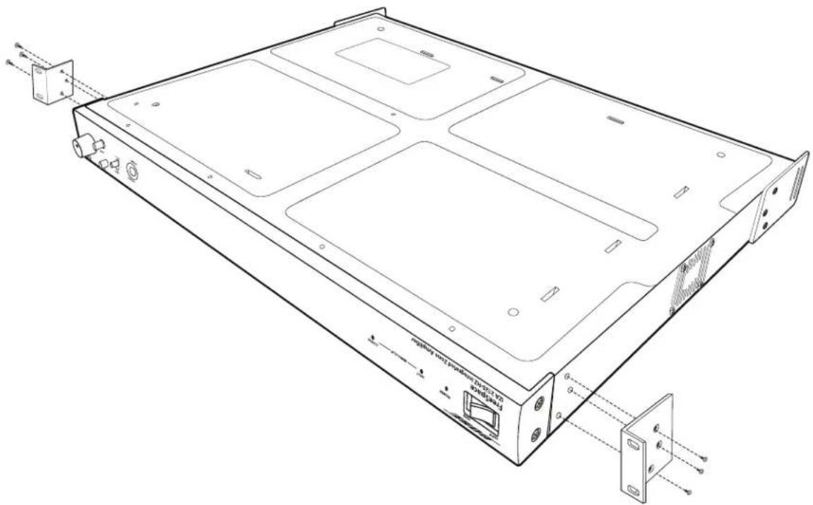
Placing on a flat surface
The amplifier can be placed on a flat, stable surface like a table, counter, or shelf. The rack-mount ears can be removed and plastic feet (included with the amplifier) can be installed to protect the surface area and prevent the chassis from sliding.
Note: When installing the amplifier in an office, conference room, or classroom, carefully place it in a way that minimizes the audible affects of the internal cooling fan of the amplifier. It is recommended to place the amplifier below ear level, in a corner, with the fan inlet (left side) pointing away from the seating area.
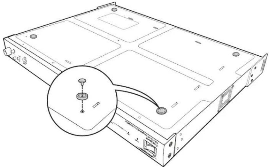
Installing the feet on the amplifier
The included feet are comprised of two parts: a foot and a pin.
- Place the amplifier upside-down on a flat, level surface on a protective covering to avoid scratching the top of the chassis.
- Insert the four feet into the four holes on the bottom of the chassis.
- Insert a pin into the hole on the foot.
- Press down on the pin until the foot locks into place. Repeat for all four feet.
Stacking units
One amplifier can be stacked on top of another when there is limited space available on a table, counter, or shelf.

Connecting an amplifier to a ControlSpace® engineered sound processor
The balanced inputs of the IZA 2120-LZ/HZ and ZA 2120-LZ/HZ can be used to easily connect to the balanced outputs of a ControlSpace engineered sound processor.
MONO Input STEREO/Dual MONO Input

Page input connections
The PAGE INPUT is a mic/line input with a trigger contact closure. This input signal is routed to all outputs (including AUX OUT) when the trigger is detected. This is designed for push-to-talk paging microphones and telephone paging systems. In VOX mode a dynamic microphone is also supported. See the diagrams below for input wiring configurations. Use the included 4-pin Euroblock.


Remote control connections
Remote volume and source selection control
The amplifier is designed to work with the Bose® volume control with A/B switch user interface accessory (PC 041967), or the volume control user interface accessory (PC 041966). The REMOTE connector on the rear panel of the amplifier is labeled to match the connector on the user interface. Use the included 4-pin Euroblock. See the appropriate Bose volume control user interface install guide for more details.
![graph TD A["Bose volume control with A/B switch"] --> B["PWR"] A --> C["VOL"] A --> D["COM"] A --> E["A/B"] B --> F["IZA 2120-LZ/Hz REMOTE"] C --> F D --> F E --> F](/content/2026/07/1488071/images/ef6e596ed74c800d09851db9cb94efa53a2675def2db05019771caebfa2a073c.jpg)
![graph TD A["Bose volume control"] --> B["PWR"] A --> C["VOL"] B --> D["IZA 2120-LZ/Hz"] C --> D D --> E["PWR"] D --> F["VOL"] D --> G["COM"] D --> H["A/B"] E --> I["REMOTE"]](/content/2026/07/1488071/images/da720f9f69d3a99f1c85f8b3e218fe80c00e716e1cff3a152154e3c3cbca13d4.jpg)
IZA 2120-HZ remote configuration examples
Configuration example 1
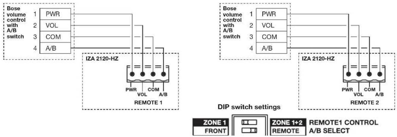
REMOTE 1 can be a Bose volume control with A/B switch user interface accessory (PC 041967). REMOTE 1 will control the level and source selection of both outputs simultaneously. This configuration requires setting the REMOTE 1 CONTROL DIP switch to ZONE 1+2 and the A/B SELECT DIP switch to REMOTE. If only one remote is being used, this switch must be set to ZONE 1+2. If this switch is set to ZONE 1, the REMOTE input will not operate, and front panel controls will be active.
![graph TD A["Bose volume control with A/B switch"] --> B["PWR"] A --> C["VOL"] A --> D["COM"] A --> E["A/B"] B --> F["IZA 2120-HZ"] C --> F D --> F E --> F F --> G["REMOTE 1"] style A fill:#f9f,stroke:#333 style G fill:#ccf,stroke:#333](/content/2026/07/1488071/images/3f112e7deb75298b65a506c9df1c0ae38cac53e38e30e76762b5df28558277f1.jpg)
Configuration example 2
REMOTE 1 and REMOTE 2 can be a Bose volume control with A/B switch user interface (PC 041967) accessory. REMOTE 1 will control the level and source selection of output one and REMOTE 2 will control the level and source selection of output two. This configuration requires setting the REMOTE 1 CONTROL DIP switch to ZONE 1 and the A/B SELECT DIP switch to REMOTE.
Configuration example 3
REMOTE 1 can be a Bose volume control with A/B switch user interface accessory (PC 041967) and REMOTE 2 can be a volume control user interface accessory (PC 041966). In this configuration, REMOTE 1 controls the level of output one and the source selection for both outputs. REMOTE 2 controls the level for output two. The A/B pin from REMOTE 1 needs to be jumpered with wire to the A/B pin on REMOTE 2. This configuration requires setting the REMOTE 1 CONTROL DIP switch to ZONE 1 and the A/B SELECT DIP switch to REMOTE. If the A/B jumper wire is not connected, output two will default to amplifying input B constantly. If output two is to amplify input A constantly, the A/B pin of REMOTE 2 needs to be jumpered to the COM pin. This configuration also works with the remote types reversed with a volume control user interface accessory (PC 041966) on REMOTE 1 and a volume control with A/B switch user interface accessory (PC 041967) on REMOTE 2.
![graph TD A["Bose volume control with A/B switch"] --> B["PWR"] A --> C["VOL"] A --> D["COM"] A --> E["A/B"] F["BOSE volume control"] --> G["PWR"] F --> H["VOL"] I["Remote 1"] --> J["PWR VOL COM A/B"] K["Remote 2"] --> L["PWR VOL COM A/B"] M["IZA 2120-HZ"] --> N["PWR VOL COM A/B"] O["Jumper wire"] --…](/content/2026/07/1488071/images/c62f81af7a49af0247ef0bb45b1bbe7b6b361f501992f48ea73185e3c7cfb651.jpg)
Configuration example 4
REMOTE 1 and REMOTE 2 can be a volume control user interface accessory (PC 041966). In this configuration, REMOTE 1 controls the level of output one and REMOTE 2 controls the level for output two. A/B source selection for both outputs is simultaneously controlled by the front panel switch. This configuration requires setting the REMOTE 1 CONTROL DIP switch to ZONE 1 and the A/B SELECT DIP switch to FRONT.
![graph TD subgraph_Left_Dip["BOSE volume control"] A1["PWR"] --> B1["VOL"] A2["VOL"] --> B1 B1 --> C1["IZA 2120-HZ REMOTE 1"] C1 --> D1["PWR VOL COM A/B"] end subgraph_Right_Dip["BOSE volume control"] E1["PWR"] --> F1["VOL"] E2["VOL"] --> F1 F1 --> G1["IZA 2120-HZ REMOTE 2"] G1 --> H1["PWR VOL COM A/…](/content/2026/07/1488071/images/0440a968cb05c2034f02481e1ab70e63eaf4afcabb04828e3da5acb1356eb276.jpg)
Configuration example 5
REMOTE 1 can be a volume control user interface accessory (PC 041966). In this configuration, REMOTE 1 controls the level of both outputs simultaneously. A/B source selection for both outputs is simultaneously controlled by the front panel switch. This configuration requires setting the REMOTE 1 CONTROL DIP switch to ZONE 1+2 and the A/B SELECT DIP switch to FRONT.
![graph TD A["Bose volume control"] --> B["PWR"] A --> C["VOL"] B --> D["IZA 2120-HZ"] C --> D D --> E["REMOTE 1"] E --> F["PWR VOL COM A/B"] style A fill:#f9f,stroke:#333 style D fill:#ccf,stroke:#333 style E fill:#cfc,stroke:#333](/content/2026/07/1488071/images/7de1078e06644b4013262a593aa26db6263bbb656870d461205e3047e80bc009.jpg)
Remote connections to zone amplifiers
Remote volume control
The zone amplifiers are designed to work with the Bose® volume control user interface accessory (PC 041966). The REMOTE connector on the rear panel of the amplifier is labeled to match the connector on the user interface. Use the included 2-pin Euroblock. See the Bose volume control user interface accessory install guide for more details.
![graph TD A["Bose volume control"] --> B["PWR"] A --> C["VOL"] B --> D["ZA 2120-LZ/Hz"] C --> D D --> E["REMOTE 1"]](/content/2026/07/1488071/images/614e5923dcbd6734049bd17648894729a127d4dd19f4bf359dd5d676b835db32.jpg)
ZA 2120-HZ remote configuration examples
Configuration example 1
REMOTE 1 can be a Bose® volume control user interface accessory (PC 041966). REMOTE 1 will control the level of both outputs simultaneously. This configuration requires setting the REMOTE 1 CONTROL switch to ZONE 1+2. If only one remote is being used, this switch must be set to ZONE 1+2. If this switch is set to ZONE 1, the REMOTE will not operate.
![graph TD A["Bose volume control"] --> B["PWR"] A --> C["VOL"] B --> D["ZA 2120-HZ"] C --> D D --> E["+ - REMOTE 1"]](/content/2026/07/1488071/images/d9fa169aa3b2ac89c6440a0f50d2b9ee926641df3551f26e9c96c64e30987216.jpg)
Switch setting
REMOTE 1 CONTROL

Configuration example 2
REMOTE 1 and REMOTE 2 can be a volume control user interface accessory (PC 041966). In this configuration, REMOTE 1 controls the level of output one and REMOTE 2 controls the level for output two. This configuration requires setting the REMOTE 1 CONTROL switch to ZONE 1.
![graph TD A["Bose volume control"] --> B["PWR"] A --> C["VOL"] B --> D["ZA 2120-HZ"] C --> D D --> E["+ - REMOTE 1"]](/content/2026/07/1488071/images/777d338f509528d02983e27a0058e447754f46df91a9094e27b473174065ccbd.jpg)
![graph TD A["Bose volume control"] --> B["PWR"] A --> C["VOL"] B --> D["ZA 2120-HZ"] C --> D D --> E["+ - REMOTE 2"]](/content/2026/07/1488071/images/1375a4acf813f2cf852efd1e15e20ab894a2c01c29e98ffc4b0203fc48883dce.jpg)
Switch setting
REMOTE 1 CONTROL

Remote input functionality
The amplifier also can be controlled with a linear taper 10k ohm potentiometer (fully CCW = 0 ohm, fully CW=10k ohm) and SPDT switch. When the SW1 switch is set to short the A/B pin to the COM pin, the amplifier switches to input A. When the SW1 switch is set to make the A/B pin open, the amplifier switches to input B.

Mute with standard contact closure
The amplifier is designed to mute all outputs (including AUX OUT) when the MUTE contacts are shorted together. Use the included 2-pin Euroblock.

Loudspeaker usage
This table shows the maximum quantity of loudspeakers supported by each IZA 2120-HZ or ZA 2120-HZ amplifier output for each loudspeaker tap setting. The data is based on the maximum output of 120 watts per each amplifier output. Do not exceed 120 W per output.
High-impedance loudspeakers per amplifier output
| Max. Qty. of Loudspeakers Per Output / Tap Setting | |||||
| FreeSpace DS 16 120 / 1W 60 / 2W 30 / 4W 15 / 8W 7 / 16W | |||||
| FreeSpace DS 40 48 / 2.5W 24 / 5W 12 / 10W 6 / 20W 3 / 40W | |||||
| FreeSpace DS 100 9 / 12.5W 4 / 25W 2 / 50W 1 / 100W | |||||
| FreeSpace 3 System 4 / 25W 2 / 50W 1 / 100W 0 / 200W | |||||
| FreeSpace 3 Acoustimass Module I or II 4 / 25W 2 / 50W 1 / 100W 0 / 200W | |||||
| FreeSpace 360P II 12 / 10W 6 / 20W 3 / 40W 1 / 80W | |||||
| RoomMatch Utility RMU105: | |||||
| with RMUXF40 Transformer 48 / 2.5W 24 / 5W 12 / 10W 6 / 20W 3 / 40W | |||||
| with RMUXF100 Transformer 9 / 12.5W 4 / 25W 2 / 50W 1 / 100W | |||||
Expansion overview
The FreeSpace® zone amplifier makes system expansion easy. When a system design requires more loudspeakers than the FreeSpace IZA 2120-LZ/HZ integrated zone amplifier can support, a FreeSpace zone amplifier can be connected to provide additional power or zones.
When connected together, the IZA 2120-LZ/HZ and any zone amplifier (ZA 2120-LZ/HZ, ZA 250-LZ, ZA 190-HZ) can operate together as one system, sharing the same music and paging sources. The IZA 2120-LZ/HZ amplifier operates as the master of the zone amplifier, determining which audio sources will be heard. The overall MASTER LEVEL volume can be controlled by the integrated zone amplifier in one larger zone, or volume control can be distributed in multi-zone installations.
Connecting an IZA 2120-LZ/HZ amplifier to a ZA 2120-LZ/HZ amplifier
Using the included RCA cable, connect the AUX OUT of the IZA 2120-LZ/HZ amplifier to the unbalanced INPUT of any zone amplifier.
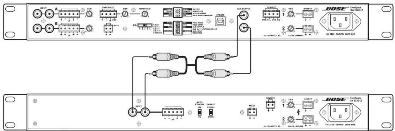
Note: It is recommended that when amplifiers are connected together, that both amplifier AC power cords are plugged into the same AC outlet to reduce potential noise issues.
Line input connections
When using a front-end signal processor, or connecting multiple zone amplifiers to an integrated zone amplifier, the included RCA cable may need to be modified. The wiring diagram for the zone amplifier line-level input RCA connectors is provided below.

Connecting an IZA 2120-LZ/HZ amplifier to multiple zone amplifiers
The auxiliary output of the IZA 2120-LZ/HZ can be connected in a star configuration to four zone amplifiers without experiencing signal loss.
Using T/S RCA connectors:

Using RCA male stackable connector cables:
![graph TD A["IAZA 2120-LZ/Hz AUX OUT"] --> B["AUX OUTPUT"] A --> C["INPUT"] D["IAZA 2120-LZ/Hz balanced input"] --> E["Zone amplifier 1"] D --> F["INPUT"] G["IAZA 2120-LZ/Hz balanced input"] --> H["Zone amplifier 2"] G --> I["INPUT"] J["IAZA 2120-LZ/Hz balanced input"] --> K["Zone amplifier 3"] J -->…](/content/2026/07/1488071/images/93881d26c2a1ad50cbbc6c3ee3f5c02635923296972db4dca2574cceff5806dd.jpg)
Troubleshooting
| Problem What to do | |
| No power • Turn on power. Blue LED on front-panel will be visible when power is on.Make sure the power cord is plugged in.Try a different AC outlet that is working with another piece of equipment. | |
| Power is on, but no sound | Make sure the input source is turned on.Verify that there is an input signal from the source.Check the cable connections from the source to the amplifier.Ensure the desired source (A/B) is selected on the front panel.If a user interface is connected to the REMOTE connector on the rear panel, make sure the desired source (A/B) is selected on user interface (user interface overrides the front-panel source select).Make sure the MASTER LEVEL control is turned up.If a user interface is connected to the REMOTE connector on the rear panel, make sure the volume control on the user interface is turned up (user interface overrides the front-panel MASTER LEVEL control).Make sure a 1/8" (3.5 mm) TRS input cable is not connected to the AUX INPUT.The AUX INPUT has a mechanical override feature so if an input cable is connected to it the selected Input A/B source will be automatically overridden - even if the AUX INPUT audio source is not playing or connected.If a contact closure is connected to the MUTE connector on the rear panel, check the switch to ensure the mute function has not been triggered.If a source is connected to the PAGE INPUT connector on the rear panel, make sure it has not been triggered.Make sure loudspeakers are connected properly.Make sure that loudspeaker taps are set correctly. See “Loudspeaker usage” on page 33.Check that the amplifier has adequate ventilation. Improper ventilation could cause the amplifier to go into protection mode and no audio will be heard.Ensure that the output wiring is correct. A short circuit will cause the amplifier to go into protection mode and no audio will be heard. |
| Power is on, but sound is low | Verify that the audio input source output is turned up to a nominal level.Check the cable connections from the source to the amplifier.Increase input level of source with GAIN controls on amplifier. Turn GAIN knob clockwise until you start seeing a red INPUT SIGNAL CLIP LED on front-panel. Then turn GAIN counter-clockwise until the LED turns green.Make sure OUTPUT TRIM controls on amplifier are not turned down too low.If a user interface is connected to the REMOTE connector on the rear panel, make sure the volume control on the user interface is turned up (user interface overrides the front-panel MASTER LEVEL control).Make sure that loudspeaker taps are set correctly. See “Loudspeaker usage” on page 33. |
| Sound is distorted | Verify that the INPUT SIGNAL CLIP LED on the front-panel is not red. If it is red, reduce the source output level or reduce the input gain.If the input source signal is clean, verify that the loudspeakers are not overdriven or damaged. Check the loudspeaker tap setting. |
| Unnatural sound | Verify that the proper EQ preset is selected for the loudspeakers being used. With the IZA 2120-HZ, use the HPF setting for loudspeakers other than FreeSpace® loudspeakers and those that have their own EQ settings.Check the TREBLE and BASS controls on the front-panels. |
AC current draw and thermal dissipation information
Amplifier rated channel power is 120 W.
| IZA 2120-LZ, AC Current Draw and Thermal Dissipation | |||||||
| Test Signal & Power Level | Load Configuration(Both IZA channels driven) | Total AudioOutput, W | 120 VAC 60 HzLine Current, A | 230 VAC 50 HzLine Current, A | Thermal Dissipation, Max | ||
| Watts BTU/hr kCal/hr | |||||||
| Power On, Idling | 0 0.16 0.13 30 102 26 | ||||||
| 1/8th Rated PowerIEC65 Bandlimited Pink Noise | 8Ω / Ch 15 0.19 0.15 34 116 29 | ||||||
| 6 dB Crest FactorDS 16 EQ Enabled | 4Ω / Ch 30 0.50 0.28 64 218 55 | ||||||
| 1/3rd Rated PowerIEC65 Bandlimited Pink Noise | 8Ω / Ch 40 0.25 0.17 39 133 34 | ||||||
| 6 dB Crest FactorDS 16 EQ Enabled | 4 Ω / Ch 80 1.00 0.539 136 464 117 | ||||||
| IZA 2120-HZ, AC Current Draw and Thermal Dissipation | |||||||
| Test Signal & Power Level | Load Configuration(Both IZA channels driven) | Total AudioOutput, W | 120 VAC 60 HzLine Current, A | 230 VAC 50 HzLine Current, A | Thermal Dissipation, Max | ||
| Watts BTU/hr. kCal/hr. | |||||||
| Power On, Idling | 0 0.27 0.17 40 136 34 | ||||||
| 1/8th Rated PowerIEC65 Bandlimited Pink Noise | 70V / Ch | 30 0.55 0.30 69 235 59 | |||||
| 6 dB Crest FactorDS 16 EQ Enabled | 100V / Ch | 30 0.61 0.33 76 259 65 | |||||
| 1/3rd Rated PowerIEC65 Bandlimited Pink Noise | 70V / Ch | 80 1.15 0.60 138 471 119 | |||||
| 6 dB Crest FactorDS 16 EQ Enabled | 100V / Ch | 80 1.15 0.64 147 502 127 | |||||
| ZA 2120-LZ, AC Current Draw and Thermal Dissipation | |||||||
| Test Signal & Power Level | Load Configuration(Both IZA channels driven) | Total AudioOutput, W | 120 VAC 60 HzLine Current, A | 230 VAC 50 HzLine Current, A | Thermal Dissipation, Max | ||
| Watts BTU/hr. kCal/hr. | |||||||
| Power On, Idling | 0 0.13 0.12 28 96 | 24 | |||||
| 1/8th Rated PowerIEC65 Bandlimited Pink Noise | 8Ω / Ch 15 0.18 0.14 32 109 28 | ||||||
| 6 dB Crest FactorDS 16 EQ Enabled | 4Ω / Ch 30 0.50 0.27 62 212 53 | ||||||
| 1/3rd Rated PowerIEC65 Bandlimited Pink Noise | 8Ω / Ch 40 0.24 0.17 39 133 34 | ||||||
| 6 dB Crest FactorDS 16 EQ Enabled | 4Ω / Ch 80 1.00 0.55 127 433 109 | ||||||
| ZA 2120-HZ, AC Current Draw and Thermal Dissipation | |||||||
| Test Signal & Power Level | Load Configuration(Both IZA channels driven) | Total AudioOutput, W | 120 VAC 60 HzLine Current, A | 230 VAC 50 HzLine Current, A | Thermal Dissipation, Max | ||
| Watts BTU/hr. kCal/hr. | |||||||
| Power On, Idling | 0 0.20 0.15 34 116 29 | ||||||
| 1/8th Rated PowerIEC65 Bandlimited Pink Noise | 70 V/ Ch | 30 0.57 0.31 71 242 61 | |||||
| 6 dB Crest FactorDS 16 EQ Enabled | 100V / Ch | 30 0.66 0.35 81 276 71 | |||||
| 1/3rd Rated PowerIEC65 Bandlimited Pink Noise | 70V / Ch | 80 1.13 0.58 133 454 114 | |||||
| 6 dB Crest FactorDS 16 EQ Enabled | 100V / Ch | 80 1.25 0.65 150 512 129 | |||||
IZA 2120-LZ specifications
| Power Rating | |||
| Amplifier Power 2 x 120 W @ 4 Ω, 2 x 60 W @ 8 Ω | |||
| Audio Performance | |||
| Frequency Response 20 Hz - 20 kHz | (+0/-3 dB, @ 1 W reference 1 kHz) | ||
| THD+N ≤ 0.5 % (at rated power) | |||
| Channel Separation (Crosstalk) ≤ -58 dBu (below rated power, 1 kHz) | |||
| Dynamic Range 88 dB | |||
| Integrated DSP | |||
| A/D and D/A Converters 24-bit / 48 kHz | |||
| Processing Functions Loudspeaker EQ, Bose Opti-voice paging, Dynamic equalization | |||
| Loudspeaker Presets Flat, FreeSpace DS 16, DS 40, DS 100, and RoomMatch Utility RMU105 | |||
| Audio Latency 10.4 ms (any input to speaker output or aux output) | |||
| Audio Inputs | |||
| Line Inputs Page Inputs Auxiliary Input | |||
| Input Channels 2 unbalanced, 2 balanced 1 balanced mic/line 1 unbalanced line | |||
| Connectors Stereo RCA, 5-pin Euroblock 4-pin Euroblock | 1/8" (3.5mm) TRS | ||
| Input Range | -8 dBu to 22 dBu | -58 dBu to 12 dBu | -60 dBu to -1 dBu |
| Adjustment Range | 0 dB to -30 dB 0 dB to +50 dB | Fixed | |
| Input Impedance | 20 kΩ | 2 kΩ | 20 kΩ |
| Maximum Input Level | 22 dBu | 12 dBu | -1 dBu |
| Sensitivity | -8 dBu | n/a | -3 dBu |
| Nominal Input Level | 4 dBu | -38 dBu | -8 dBu |
| Audio Outputs | |||
| Amplifier Outputs | Auxiliary Output | ||
| Outputs | 2 | 1 unbalanced | |
| Connectors, Output | 2-pin inverted Euroblock | Stereo RCA | |
| Output Impedance | 4 Ω | 150 Ω | |
| Nominal Output Level | 2 x 120 W @ 4 Ω, 2 x 60 W @ 8 Ω | 2 dBu | |
| Indicators and Controls | |||
| Power LED | Solid blue indicates power is on, blinking blue indicates standby mode | ||
| Input Signal Clip LED | Green indicates input signal is within -37 dBu to 11 dBu, red indicates signal is over 11 dBu, master level set at 5 | ||
| Output Signal Clip LED | Green indicates output signal is within -46 dBFS to -2 dBFS red indicates signal is over -2 dBFS, approximately 80 W/channel, for each output 120 watts is 0 dBFS | ||
| Controls, Front Panel | Power On/Off, Input Select (A/B), Treble/Bass Tone Controls, Master Level | ||
| Controls, Rear Panel | Amplifier Mode DIP switches, Loudspeaker EQ preset selector, Input Gain (A/B/Page), Output trims, Remote | ||
| Electrical | |||
| Mains Voltage | 100 VAC - 240V AC (±10%, 50/60 Hz) | ||
| AC Power Consumption 24 W (Standby), 300 W (Max) | |||
| Mains Connector | Standard IEC (C14) | ||
| Maximum Inrush Current | 12.6 Amps (230 VAC / 50 Hz), 6.6 Amps (120 VAC / 60 Hz) | ||
| Overload Protection | High temperature, output short, excessively low or high AC line voltage | ||
| Physical | |||
| Dimensions 1.7" H x 19.0" W x 12.8" | D (44 mm x 483 mm x 324 mm) | ||
| Shipping Weight | 12.0 lb (5.4 kg) | ||
| Net Weight | 9.0 lb (4.1 kg) | ||
| Cooling System Single fan creates continuous left-to-right air flow | |||
| General | |||
| Inputs (Control) | Remote input for Volume Control with A/B Select user interface (PC041967), Volume Control user interface (PC041966), Mute input control via a normally open contact closure | ||
IZA 2120-HZ specifications
| Power Rating | |||
| Amplifier Power 2 x 120 W @ 70/100V | |||
| Audio Performance | |||
| Frequency Response 55 Hz - 20 kHz (+0/-3 dB, @ 1 W reference 1 kHz) | |||
| THD+N ≤ 0.3 % (at rated power) | |||
| Channel Separation (Crosstalk) ≤ -58 dBu (below rated power, 1 kHz) | |||
| Dynamic Range 88 dB | |||
| Integrated DSP | |||
| A/D and D/A Converters 24-bit / 48 kHz | |||
| Processing Functions Loudspeaker EQ, Bose Opti-voice® paging, Dynamic equalization | |||
| Loudspeaker Presets FreeSpace® FS3/HPF, DS 16, DS 40, DS 100, and FS3B | |||
| Audio Latency 10.4 ms (any input to speaker output or aux output) | |||
| Audio Inputs | |||
| Line Inputs Page Input Auxiliary Input | |||
| Input Channels 2 unbalanced, 2 balanced 1 balanced mic/line 1 unbalanced line | |||
| Connectors | Stereo RCA, 5-pin Euroblock | 4-pin Euroblock | 1/8" (3.5mm) TRS |
| Input Range | -8 dBu to 22 dBu | -58 dBu to 12 dBu | -60 dBu to -1 dBu |
| Adjustment Range | 0 dB to -30 dB | 0 dB to +50 dB | Fixed |
| Input Impedance | 20 kΩ | 2 kΩ | 20 kΩ |
| Maximum Input Level | 22 dBu | 12 dBu | -1 dBu |
| Sensitivity | -8 dBu | n/a | -3 dBu |
| Nominal Input Level | 4 dBu | -38 dBu | -8 dBu |
| Audio Outputs | |||
| Amplifier Outputs | Auxiliary Output | ||
| Outputs | 2 | 1 unbalanced | |
| Connectors | 2-pin inverted Euroblock | Stereo RCA | |
| Output Impedance | n/a | 400 Ω | |
| Nominal Output Level | 2 x 120 W @ 70/100V | 2 dBu | |
| Indicators and Controls | |||
| Power LED | Solid blue indicates power is on, blinking blue indicates standby mode | ||
| Input Signal Clip LED | Green indicates input signal is within -37 dBu to 11 dBu, red indicates signal is over 11 dBu, master level set to 5 | ||
| Output Signal Clip LED | Green indicates output signal is within -46 dBFS to -2 dBFS, red indicates signal is over -2 dBFS, approximately 80 W/channel, for each output 120 watts is 0 dBFS | ||
| Controls, Front Panel | Power On/Off, Input Select (A/B), Treble/Bass Tone Controls (x2), Master Level | ||
| Controls, Rear Panel | Amplifier Mode DIP switches, Loudspeaker EQ preset selector, Input Gain (A/B/Page), Output trims, Remote (x2) | ||
| Electrical | |||
| Mains Voltage | 100 VAC - 240 VAC (±10%, 50/60 Hz) | ||
| AC Power Consumption 26 W (Standby), 300 W (Max) | |||
| Mains Connector | Standard IEC (C14) | ||
| Maximum Inrush Current | 12.6 Amps (230 VAC / 50 Hz), 6.6 Amps (120 VAC / 60 Hz) | ||
| Overload Protection | High temperature, output short, excessively low or high AC line voltage | ||
| Physical | |||
| Dimensions | 1.7" H x 19.0" W x 12.8" D (44 mm x 483 mm x 324 mm) | ||
| Shipping Weight 12.0 lb (5.4 kg) | |||
| Net Weight | 9.0 lb (4.1 kg) | ||
| Cooling System Single fan creates continuous left-to-right air flow | |||
| General | |||
| Inputs (Control) | Remote input for Volume Control with A/B Select user interface (PC041967), Volume Control user interface (PC041966), Mute input control via a normally open contact closure | ||
ZA 2120-LZ specifications
| Power Rating | |
| Amplifier Power 2 x 120 W @ 4 Ω, 2 x 60 W @ 8 Ω | |
| Audio Performance | |
| Frequency Response 20 Hz - 20 kHz (+0/-3 dB, @ 1 W reference 1 kHz) | |
| THD+N ≤ 0.5 % (at rated power) | |
| Channel Separation (Crosstalk) ≤ -58 dBu (below rated power, 1 kHz) | |
| Dynamic Range 88 dB | |
| Audio Inputs | |
| Input Channels 1 unbalanced, balanced | |
| Connectors Stereo RCA, 5-pin Euroblock | |
| Input Range -8 dBu to 22 dBu | |
| Input Impedance 20 kΩ | |
| Maximum Input Level 22 dBu | |
| Nominal Input Level 4 dBu | |
| Audio Outputs | |
| Outputs 2 | |
| Connectors 2-pin inverted Euroblock | |
| Nominal Output Level 2 x 120 W @ 4 Ω, 2 x 60 W @ 8 Ω | |
| Indicators and Controls | |
| Power LED Solid blue indicates power is on, blinking blue indicates standby mode | |
| Input Signal Clip LED Green indicates input signal is within -37 dBu to 11 dBu, red indicates signal is over 11 dBu | |
| Output Signal Clip LED | Green indicates output signal is within -46 dBFS to -2 dBFS, red indicates signal is over -2 dBFS, approximately 80 W/channel, for each output 120 watts is 0 dBFS |
| Controls, Front Panel | Power On/Off |
| Controls, Rear Panel | Auto Standby: On/Off switch, Output: Stereo/Mono switch, Mute, Output trims, Remote |
| Electrical | |
| Mains Voltage | 100 VAC - 240 VAC (±10%, 50/60 Hz) |
| AC Power Consumption | 21 W (Standby), 300 W (Max) |
| Mains Connector | Standard IEC (C14) |
| Maximum Inrush Current | 12.6 Amps (230 VAC / 50 Hz), 7.8 Amps (120 VAC / 60 Hz) |
| Overload Protection | High temperature, output short, excessively low or high AC line voltage |
| Physical | |
| Dimensions 1.7" H x 19.0" W x 12.8" D (44 mm x 483 mm x 324 mm) | |
| Shipping Weight | 11.5 lb (5.2 kg) |
| Net Weight | 8.5 lb (3.9 kg) |
| Cooling System Single fan creates continuous left-to-right air flow | |
| General | |
| Inputs (Control) | Remote input for Volume Control (PC041966), Mute input control via a normally open contact closure |
ZA 2120-HZ specifications
| Power Rating | |
| Amplifier Power 2 x 120 W @ 70/100V | |
| Audio Performance | |
| Frequency Response 55 Hz - 20 kHz | (+0/-3 dB, @ 1 W reference 1 kHz) |
| THD+N ≤ 0.3 % (at rated power) | |
| Channel Separation (Crosstalk) ≤ -58 dBu (below rated power, 1 kHz) | |
| Dynamic Range 88 dB | |
| Audio Inputs | |
| Input Channels 1 unbalanced, 1 balanced | |
| Connectors Stereo RCA, 5-pin Euroblock | |
| Input Range -8 dBu to 22 dBu | |
| Input Impedance 20 kΩ | |
| Maximum Input Level 22 dBu | |
| Nominal Input Level 4 dBu | |
| Audio Outputs | |
| Outputs 2 | |
| Connectors 2-pin inverted Euroblock | |
| Nominal Output Level 2 x 120 W @ 70/100V | |
| Indicators and Controls | |
| Power LED Solid blue indicates power is on, blinking blue indicates standby mode | |
| Input Signal Clip LED Green indicates input signal is within -37 dBu to 11 dBu, red indicates signal is over 11 dBu | |
| Output Signal Clip LED | Green indicates output signal is within -46 dBFS to -2 dBFS, red indicates signal is over -2 dBFS, approximately 80 W/channel, for each output 120 watts is 0 dBFS |
| Controls, Front Panel | Power On/Off |
| Controls, Rear Panel | Auto Standby: On/Off switch, Input: Dual/Summed switch, Remote 1 Control: Zone 1/Zone 1+2 switch, Output Voltage: 70/100V switch, Mute, Output trims, Remote (x2) |
| Electrical | |
| Mains Voltage | 100 VAC - 240 VAC (±10%, 50/60 Hz) |
| AC Power Consumption | 23 W (Standby), 300 W (Max) |
| Mains Connector | Standard IEC (C14) |
| Maximum Inrush Current | 12.6 Amps (230 VAC / 50 Hz), 7.8 Amps (120 VAC / 60 Hz) |
| Overload Protection | High temperature, output short, excessively low or high AC line voltage |
| Physical | |
| Dimensions 1.7" H x 19.0" W x 12.8" | D (44 mm x 483 mm x 324 mm) |
| Shipping Weight | 11.5 lb (5.2 kg) |
| Net Weight | 8.5 lb (3.9 kg) |
| Cooling System Single fan creates continuous left-to-right air flow | |
| General | |
| Inputs (Control) | 2 remote inputs for Volume Control (PC041966), Mute input control via a normally open contact closure |
IZA 2120-LZ Integrated Zone Amplifier
![graph TD A["Input A: 5.7p functions"] --> B["A/6 sources (fprint/furnon)"] B --> C["Aux input switch (fprint/furnon)"] C --> D["AUX flow rate"] D --> E["Max/Min power switch (forn/fn)"] E --> F["Macro/Staro"] F --> G["Level/DC"] G --> H["Output 1: 20W @ 4.0"] H --> I["PWR AMP1"] I --> J["Output 2: 1…](/content/2026/07/1488071/images/13bf74f561fa4343c6ffcce7f36feb4f70773d764efb94fbe0e8987e847e289b.jpg)
![graph TD subgraph "Digital Signal Processor" direction TB A["Input A: S-Pin Balanced"] --> B["Input A: Unbalanced"] C["Input B: S-Pin Balanced"] --> D["Input B: Unbalanced"] E["Aux Input (Override)"] --> F["Aux Input"] G["Mic/Line Page Input"] --> H["PTT"] end B --> I["Gain"] D --> J["Gain"] I --> K…](/content/2026/07/1488071/images/ea26534ab1994a347d0733479e44d7f49c0a52324fb0e88c33a6bf1253a9e38c.jpg)
IZA 2120-HZ Integrated Zone Amplifier
ZA 2120-LZ Zone Amplifier
![graph TD A["Input 120W @4.0"] --> B["PWR AMP1"] A --> C["PWR AMP2"] D["Output 120W @4.0"] --> E["PWR AMP1"] B --> F["Output Level Detect"] C --> G["Output Level Detect"] F --> H["Output Times"] G --> I["Output Times"] H --> J["Mute On/Off"] I --> K["Mute On/Off"] J --> L["Power Levels LED"] K --> M[…](/content/2026/07/1488071/images/0724101ebf6a2b33d6502cf4c2c8607560372dec48952b1e9dba56f0f15987de.jpg)
![graph TD A["Unbalanced Input"] --> B["5-Pin Balanced Input"] B --> C["Σ"] C --> D["Input Switch: (Dual/Summed)"] D --> E["Limiter/ 55 Hz HPF"] E --> F["Input Level Detect"] F --> G["Mute On/Off"] G --> H["Output Trims"] H --> I["Output Level Detect"] I --> J["PWR AMP1"] J --> K["Output 1 120 W @ 70/…](/content/2026/07/1488071/images/9ad50030c2c390cfbf5fe1b9b0f432d98f4121e1a097f6a8b466005847305852.jpg)
ZA 2120-HZ Zone Amplifier
Visit us on the web at pro.Bose.com for more information, including specifications, technical literature, product warranty, parts and accessories, and global support contact information.
Americas
(USA, Canada, Mexico, Central America, South America)
Bose Corporation
The Mountain
Framingham, MA 01701 USA
Corporate Center: 508-879-7330
Americas Professional Systems,
Technical Support: 800-994-2673
Australia
Bose Pty Limited
Unit 3/2 Holker Street
Newington NSW Australia
61 2 8737 9999
Belgium
Bose N.V. / S.A
Limesweg 2, 03700
Tongeren, Belgium
012-390800
China
Bose Electronics (Shanghai) Co Ltd
25F, L'Avenue
99 Xianxia Road
Shanghai, P.R.C. 200051 China
86 21 6010 3800
France
Bose S.A.S
1 Matheson Street, Causeway Bay, Hong Kong
852 2123 9000
India
Bose Corporation India Private Limited
Salcon Aurum, 3rd Floor
Plot No. 4, Jasola District Centre
New Delhi - 110025, India
91 11 43080200
Italy
Bose SpA
Centro Leoni A – Via G. Spadolini
5 20122 Milano, Italy
39-02-36704500
Japan
Bose Kabushiki Kaisha
Sumitomo Fudosan Shibuya Garden Tower 5F
16-17, Nanpeidai-cho
Shibuya-Ku, Tokyo, 150-0036, Japan
TEL 81-3-5489-0955
www.bose.co.jp
The Netherlands
Bose BV
1 Ambley Green, Gillingham Business Park
KENT ME8 0NJ
Gillingham, England
0870-741-4500
See website for other countries
BOSE® Better sound through research®


- FREESPACE® IZA 2120-LZ & IZA 2120-HZ
- FREESPACE® ZA 2120-LZ & ZA 2120-HZ
- FRONT AND REAR PANELS
- INSTALLATION AND PLACEMENT
- MAKING CONNECTIONS
- EXPANDING AN IZA SYSTEM WITH A ZA AMPLIFIER
- TECHNICAL INFORMATION
- BLOCK DIAGRAMS
- ADDITIONAL RESOURCES
- FREESPACE IZA 2120-LZ / IZA 2120-HZ INTEGRATED ZONE AMPLIFIER
- FREESPACE ZA 2120-LZ / ZA 2120-HZ ZONE AMPLIFIER
- INCLUDED ACCESSORIES
- LIMITED WARRANTY
- FREESPACE® IZA 2120-LZ
- IZA 2120-LZ REAR PANEL
- FREESPACE® IZA 2120-HZ
- IZA 2120-HZ REAR PANEL
- FREESPACE® ZA 2120-LZ/HZ
- IMPORTANCE OF PROPER VENTILATION
- REMOVING RACK-MOUNT EARS
- PLACING ON A FLAT SURFACE
- INSTALLING THE FEET ON THE AMPLIFIER
- STACKING UNITS
- CONNECTING AN AMPLIFIER TO A CONTROLSPACE® ENGINEERED SOUND PROCESSOR
- PAGE INPUT CONNECTIONS
- REMOTE CONTROL CONNECTIONS
- REMOTE VOLUME AND SOURCE SELECTION CONTROL
- IZA 2120-HZ REMOTE CONFIGURATION EXAMPLES
- CONFIGURATION EXAMPLE 1
- CONFIGURATION EXAMPLE 2
- CONFIGURATION EXAMPLE 3
- CONFIGURATION EXAMPLE 4
- CONFIGURATION EXAMPLE 5
- REMOTE CONNECTIONS TO ZONE AMPLIFIERS
- REMOTE VOLUME CONTROL
- ZA 2120-HZ REMOTE CONFIGURATION EXAMPLES
- REMOTE INPUT FUNCTIONALITY
- MUTE WITH STANDARD CONTACT CLOSURE
- LOUDSPEAKER USAGE
- EXPANSION OVERVIEW
- CONNECTING AN IZA 2120-LZ/HZ AMPLIFIER TO A ZA 2120-LZ/HZ AMPLIFIER
- LINE INPUT CONNECTIONS
- CONNECTING AN IZA 2120-LZ/HZ AMPLIFIER TO MULTIPLE ZONE AMPLIFIERS
- AC CURRENT DRAW AND THERMAL DISSIPATION INFORMATION
- AMERICAS
- AUSTRALIA
- BELGIUM
- CHINA
- FRANCE
- INDIA
- ITALY
- JAPAN
- THE NETHERLANDS
Brand : BOSE
Model : FreeSpace ZA 2120-LZA
Category : Receiver