
RM 2555 - Refrigerator DOMETIC - Free user manual and instructions
Find the device manual for free RM 2555 DOMETIC in PDF.
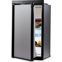


| Product Type | Absorption Refrigerator for Recreational Vehicles |
| Brand | Dometic |
| Model | RM 2555 |
| Total Capacity | 5.0 cu ft (142 L) |
| Fresh Food Capacity | 3.6 cu ft (102 L) |
| Freezer Capacity | 1.4 cu ft (40 L) icebox |
| Power Sources | 120V AC (electric), 12V DC (battery), LP Gas |
| Dimensions (H x W x D) | 31.4 x 21.7 x 23.8 inches (798 x 551 x 604 mm) |
| Weight | 52.9 lbs (24 kg) |
| Installation Type | Built-in or freestanding (with trim kit) |
| Color | White |
| Energy Source Auto Selection | Automatic switching between AC, DC, and gas |
| Ignition | Automatic electronic ignition for gas operation |
| Cooling System | Absorption cooling unit with no moving parts |
| Thermostat | Adjustable temperature control with knob |
| Interior Lighting | LED light for fresh food compartment |
| Door Reversibility | Door hinges reversible for left or right opening |
| Defrost | Manual defrost for freezer compartment |
| Leveling | Leveling feet for stable installation |
| Ventilation Requirements | Proper airflow required; top and bottom vents needed |
| Cooling Unit Warranty | Limited lifetime warranty on cooling unit |
| Maintenance Tips | Clean condenser fins and door seals regularly; use an RV-specific cleaner |
| Safety Features | Gas safety valve, flame failure device, and lockable door option |
Frequently Asked Questions - RM 2555 DOMETIC
User questions about RM 2555 DOMETIC
0 question about this device. Answer the ones you know or ask your own.
Ask a new question about this device
Download the instructions for your Refrigerator in PDF format for free! Find your manual RM 2555 - DOMETIC and take your electronic device back in hand. On this page are published all the documents necessary for the use of your device. RM 2555 by DOMETIC.
USER MANUAL RM 2555 DOMETIC
- Open windows and door.
- Don't touch electrical switches.
- Extinguish any open flame.
- Turn off the gas supply at the source.
- Contact a qualified person.
FOR YOUR SAFETY
Do not store or use gasoline or other flammable vapors and liquids in the vicinity of this or any other appliance.

WARNING
Improper installation, adjustment, alteration, service or maintenance can cause injury or property damage. Refer to this manual. For assistance or additional information consult a qualified installer, service agency or the gas supplier.
INSTALLATION
&
OPERATING
INSTRUCTIONS
AES III
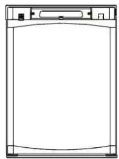
RM2355

RM2455
RM2555

RM4605
RM4805
INTRODUCTION
We are pleased that you have chosen this refrigerator and hope you will derive much satisfaction from using it.
The refrigerator is designed for installation in motorhomes and intended for storage of foods, frozen foods and making ice. It comes with Automatic Energy Selector (AES) which controls operation and energy supply. To put the refrigerator in operation, just trip the main switch - AES manages the rest.
Read this manual very carefully before using the refrigerator. Make sure to retain it for future reference. In this manual you will find information on how to install, operate and maintain your new appliance. To ensure good refrigeration and economical operation, the refrigerator has to be installed and used as described in these instructions.
The installation must be performed by an authorised person and in accordance with the manufacturers installation instructions, local gas fitting regulations, municipal building codes, electrical wiring regulations, AS5601 “Gas Installations” and any other statutory regulations.
TRANSIT DAMAGE
Before you install your refrigerator, ensure to remove all protective packaging. Check for any damage or marks. Transit damage must be reported to whoever is responsible for delivery not later than seven days after the refrigerator was delivered.
DATA PLATE
Check the data plate, inside the refrigerator, to ensure that you have received the right model.
Below you can make a note of the details stated on the data plate. It is a good idea to this since this information is needed if you have to contact service personnel. The data plate contains e.g. the following details:
| Model designation | RM .... |
| Product number | ...... |
| Serial number | ...... |
| Voltage | 230 - 240 volts |
| Gas pressure | 2,70 kPa |
CONTENTS
OPERATING INSTRUCTIONS 4
CONTROL PANEL 4
AES 4
STARTING THE REFRIGERATOR ....4
LP GAS OPERATION 4
SWITCHING BETWEEN ENERGY SOURCES ....5
REGULATING THE TEMPERATURE 5
TRAVEL CATCH....5
USING THE REFRIGERATOR....5
DEFROSTING 5
CLEANING THE REFRIGERATOR 5
AIRING POSITION CARD 6
REPLACING THE BULB 7
HEATING CABLE (RM4605 & RM4805) 7
TURNING OFF THE REFRIGERATOR ....7
PRODUCT CARE - SOME USEFUL HINTS 7
TROUBLESHOOTING 7
MAINTENANCE 7
SERVICE AND SPARE PARTS 7
INSTALLATION INSTRUCTIONS 8
GENERAL INFORMATION 8
VENTILATION OF THE UNIT 8
TECHNICAL DATA 9
CONNECTING POINTS 10
BUILDING-IN 12
SECURING THE REFRIGERATOR 12
DRAIN WATER HOSE 13
CONNECTIONS 13
MOUNTING INSTRUCTIONS 15
APPENDIX A - REARVIEW EQUIPMENT 16
APPENDIX B - WIRING DIAGRAM .....17
APPENDIX C - WORKING INSTRUCTIONS FOR THE GAS SAFETY SYSTEM 19
OPERATING INSTRUCTIONS
CONTROL PANEL
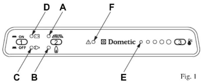
- ON/OFF button (main power button)
- AES/GAS mode selector button
- Temperature selector button
A. AES mode indicator lamp B. GAS mode indicator lamp C. AC mode indicator lamp D. DC mode indicator lamp E. Temperature indicator lamp F. Warning indicator lamp (gas failure)
AES
The refrigerator is equipped with an Automatic Energy Selector (AES) controlling the operation and energy supply.
NOTE! 12V must always be available to supply the electronics.
The system selects the available energy source in the order:
- 230-240V
- 12V
- ULP gas
Turn off the AES function if you want the refrigerator to run on ULP gas only.
STARTING THE REFRIGERATOR

WARNING
Whilst mobile:
- Do not operate the refrigerator on ULP gas
- Turn off the gas bottle.

- Press the ON/OFF button (1). The refrigerator starts in the mode it was in when it was turned off.
- Press the AES/GAS button (2) and LED (A) or (B) comes on. Select AES or ULP gas only by pressing the AES/GAS button (2) once if necessary.
- If a 230V-240V mains supply is available:
- AES selects this as the energy source and LEDs (A) and (C) come on.
- When the vehicle's engine is running, AES selects 12V operation and LEDs (A) and (D) are illuminated unless ULP gas only operation has been selected manually.
If neither mains nor a 12V battery supply are available:
- AES selects ULP gas operation and LEDs(A) and(B) come on.
ULP gas-only operation can be selected by pressing the AES/GAS button (2) until LED (B) comes on; the AES function is then turned off and LED (A) goes out. The Temperature selector button (3) is used to set the electronic thermostat. The LEDs (E) show the value set on the thermostat.
UNIVERSAL LP GAS OPERATION
AES will select ULP gas operation under the following conditions:
No AC (230-240V) available
Engine not running (no high current at 12V DC available)
When the system chooses ULP gas operation, the flame failure device is automatically opened, allowing the gas to flow to the burner. At the same time, the electronic igniter is energized.
After initial installation, servicing, or changing gas cylinders etc., the gas pipes may contain some air that should be allowed to escape by briefly turning on the refrigerator or other appliances. This will ensure that the flame lights immediately.
If the flame goes out (by gust of wind etc.), the reigniter will automatically relight the flame.

The control electronics and the igniter must have 12V DC (battery) supply to operate!
UNIVERSAL LP GAS TROUBLESHOOTING
If the Warning indicator lamp (F) is lit, there has been a failure of gas operation.
To troubleshoot, follow these steps:

Turn off the refrigerator. (Press the ON/OFF (1) to "OFF".)
Check that there is enough gas in the gas bottle, 2. that its valve is open and that any valves in the gas line to the refrigerator are open.
Turn on the refrigerator again. (Press the ON/OFF button (1) to "ON".) After 10 sec. AES will repeat the ignition sequence.
Should the warning lamp come on again after approx. 6 minutes, the failure is still present. Repeat the procedure once more. If this does not help, contact an authorized service provider in your area.
ABNORMAL OPERATION
Any of the following are considered to be abnormal operation and may require servicing:
Yellow tipping of the burner flame.
Sooting up area surrounding burner.
- Burner not igniting properly.
- Burner failing to remain alight.
In case the appliance fails to operate correctly, contact an authorized Dometic Service Centre.
230-240V OPERATION
When a mains connection is available, AES will select this. Please note, that even being in AC mode, 12V DC is necessary for the internal supply of the electronics.
12V OPERATION
AES will select the 12V mode of operation as soon as the vehicle engine is running (detected by the alternator connection of the fridge D+).
If the 12V DC goes down below 9V DC, the system will shut down completely.
SWITCHING BETWEEN ENERGY SOURCES
When switching from one energy source to another, there are some delays implemented in the AES system. The 15 min. delay between switching off the engine and starting gas mode is intended to delay the starting of gas mode e.g. when stopping at a filling station.

WARNING
It is not allowed to have a naked flame at a gas filling station. If you are not sure that your stop is shorter than 15 minutes, you are advised to set the ON/OFF switch (1) to "OFF" when stopping at a filling station.
REGULATING THE TEMPERATURE
The position number refers to Fig. 1.
It will take a few hours for the refrigerator to reach normal operating temperature. So we suggest you start it well in advance of a trip and, if possible, store it with precooled foodstuffs.
The temperature of the refrigerator main compartment is set for all three sources of energy by means of the Temperature selector button (3). After turning on the refrigerator, the system automatically chooses the mid-position. With some experience, you will soon find a suitable setting; bigger circles indicate lower temperatures. This normally does not need resetting because the same thermostat controls the main compartment temperature for any of the three sources of energy.
TRAVEL CATCH
Make sure that the travel catch is engaged when the motorhome is on the move.
USING THE REFRIGERATOR

WARNING
DO NOT store explosive substances in the refrigerator, such as cigarette lighter gas, gasoline, ether, or the like.
FOOD STORAGE
Always keep food in closed containers. Never put hot food in the refrigerator; allow it to cool first.
The frozen food compartment is intended for the storage of frozen food and for making ice. Most kinds of frozen food can be stored in the frozen food compartment for about a month. This period of time may vary, however, and it is important to follow the instructions on the individual packages.
ICE MAKING
Fill the ice tray to just below the brim with drinking water and place them on the bottom of the freezer compartment. Ice will be made more rapidly if the thermostat is set at its highest position (biggest circle), but be sure to move the thermostat back to normal setting when the ice is formed; the refrigerator might otherwise become too cold.
DEFROSTING
Frost will gradually accumulate on the refrigerating surfaces. Each time the door is opened some of the cold air in the refrigerator spills out and is replaced by warm moist room air. As this air is cooled, the moisture is deposited onto the evaporator coils or other cold surfaces inside the refrigerator and can cause frost build-up.
It is important that you do not leave the unit's door open any longer than necessary. This will reduce frost formation and increase the efficiency of your refrigerator.
The frost must not be allowed to grow too thick as it acts as an insulator and adversely affects refrigerator performance. Check the formation of frost regularly every week and when it gets about 3 mm thick, defrost the refrigerator.
Do not try to accelerate defrosting by using any kind of heating appliance, as this might damage the plastic surfaces of the refrigerator. Neither should any sharp objects be used to scrape off the ice.

To defrost the refrigerator, follow these steps:

Turn off the refrigerator. (Press the ON/OFF button (1) to "OFF".)
Empty the refrigerator.
Leave the drip tray under the finned evaporator.
Leave the cabinet and freezer door open.
Defrost water runs from the drip tray through a plastic drain water hose to the outside of the vehicle.
When all the frost has melted - dry the interior of the refrigerator with a clean cloth and replace the ice trays.
Turn on the refrigerator. Set the thermostat to the coldest position for a few hours and then, reset to the desired setting.
Place the food items back inside.
CLEANING THE REFRIGERATOR
Clean the inside of the refrigerator regularly to keep it fresh and hygienic.
Never use detergents, scouring powder, strongly scented products or wax polish to clean the interior of the refrigerator as they may damage the surfaces and leave a strong odour.

Soak a cloth in a solution consisting of a teaspoon of bicarbonate of soda to half a litre of warm water. Wring out the cloth and use it to clean the interior of the refrigerator and its fittings.
The exterior of the refrigerator should be wiped clean now and then, using a damp cloth and a small quantity of detergent. But not the door gasket, which should only be cleaned with soap and water and then thoroughly dried.
The cooling unit behind the refrigerator should be cleaned with a brush from time to time. Make sure that the refrigerator is switched off when doing this!
AIRING POSITION CARD
Use the Airing Position Card to keep the doors ajar if the refrigerator will not be in use for an extended period of time or put in storage.

RM2455/RM2555
RM4605/RM4805
REPLACING THE BULB
To replace the bulb, follow these steps:

Remove the lamp cover. 1.
RM4605/RM4805: Push the lamp cover backwards.
Replace the old bulb with an appliance bulb of the 2. same wattage (12V, max 10W).
Replace the cover.
HEATING CABLE (RM4605 & RM4805)
During the summer months of high temperatures and humidity, the metal frame between the freezer and fresh food compartments may have water droplets forming. This refrigerator comes standard with a 12V DC heating cable that will evaporate the water droplets when they form.
To have the heating cable on, position the switch located beneath the control panel to I, see Fig. 2. The heating cable can be left on continuously or only used when temperatures require it.

Fig. 2

The heating cable will draw 12V DC power continuously when in the ON (I) position. It should be turned off when a charging source is not available.
If the refrigerator is not to be used for some time:

Turn off the refrigerator. (Press the ON/OFF button (1) to "OFF".)
Shut off any on-board valve in the gas line to the refrigerator.
Pull out the plug from the wall socket.
Empty the refrigerator. Defrost and clean it as described earlier. Leave the doors of the refrigerator and frozen food compartment ajar.
PRODUCT CARE - SOME USEFUL HINTS
Make sure that:
Defrosting is carried out periodically.
The refrigerator is clean and dry with the door left open when it is not to be used for some time.
Liquids or items with a strong odour are well packed.
The ventilation openings are unobstructed.
The doors are secured by means of the travel catch when the motorhome is on the move.
TROUBLESHOOTING
IF THE REFRIGERATOR FAILS TO WORK
Before calling an authorised service technician:
Ensure that the instructions in this manual have been followed.
- Check to make sure that the refrigerator is not tilted excessively.
- Verify that the LEDs on the control panel are lit when the ON/OFF button (1) is turned on. (12V must be available.)
- If the mains voltage is connected but the refrigerator stays in gas operation -> is the refrigerator correctly connected to the 240 volt power point and is it turned on?
- If the refrigerator does not operate in DC mode when the engine is running -> is the alternator (D+) connection made correctly?
- If the Warning indicator lamp (F) lights up -> see "GAS TROUBLESHOOTING" for further information.
THE REFRIGERATOR IS NOT COLD ENOUGH
If the refrigerator is not cold enough it may be because:
- The ventilation is inadequate owing to reduced area of the ventilation passages • The evaporator is frosted up.
- The temperature control setting is incorrect.
- The gas pressure is incorrect - check the pressure regulator at the gas container. • The ambient temperature is too high.
- Too much food is loaded at one time.
- The door is not properly closed or the magnetic sealing strip is defective.
If the refrigerator still does not work properly, call an authorized service technician.

WARNING
The sealed cooling system must not be opened, since it contains corroding chemicals under high pressure.
MAINTENANCE
- This appliance must be serviced by an authorized person. We recommend that an authorized service technician checks the refrigerator once a year.
- The “Installation and operating instructions manual” should always be available.
- Ensure that the gas safety shut-off valve is working properly.
- Make sure that the ventilation openings are unobstructed.
- See to it that the burner is clean and free from combustible material.
- All connections in the ULP gas system should be checked for gas leaks. Connections can be tested for leaks using a soap solution. DO NOT use a naked flame! If there is any suspicion of damage, call for an authorized service technician.
SERVICE AND SPARE PARTS
Service and spare parts are obtainable from your dealer or Dometic - consult the telephone directory.
INSTALLATION INSTRUCTIONS
GENERAL INFORMATION
The refrigerator is intended for installation in caravans and motor homes and the information relates to this application. A correct installation is important for correct operation of the appliance.
The refrigerator must be installed on a solid floor and must be level. With the vehicle levelled, the refrigerator should be level both ways in the freezer compartment.
Free air circulation over the fins of the cooling unit is essential.
VENTILATION OF THE UNIT
VENTILATION GRILLES
We recommend fitting the appropriate Dometic ventilation system which is specially developed by Dometic for this purpose. The Dometic ventilation grilles permit inspection and small repairs to be carried out without the necessity of removing the refrigerator from the recess.
If the grille is low at floor level where leaking gas can escape, a hole a minimum of 40 mm diameter should be made in the floor of the recess to drain any unburned gas to the outside.
SIDE VENTILATION
The refrigerator unit is ventilated via two openings in the wall of the vehicle. Fresh air enters through the lower opening and warm air is discharged through the upper vent.
The lower opening should be located at floor level to allow any leaking gas to escape to the outside. The upper ventilation opening should be located above the condenser, as high as possible, to ensure good ventilation.
ROOF VENTILATION
The ventilation of the cooling unit can also be done via one opening in the wall of the vehicle and one on the roof for the roof vent.
Fresh air enters through the lower opening and warm air is discharged through the roof vent. The lower opening should be located at floor level to allow any leaking gas to escape to the outside.
The ventilation passage at the rear of the recess, between the outer wall of the vehicle and the refrigerator, must be sealed off against the living space, so cold draughts are excluded (winter camping) and no flue gases can penetrate into the vehicle.
The exhaust gases must be directed through the wall to the outside of the vehicle using a separate gas flue exhaust fitting, part number 3776 (see the following diagrams).
VENTILATION HEIGHTS

In high ambient temperatures, the refrigeration unit will only perform adequately when properly ventilated.
Recommended RM2355 ventilation system
Ventilation system not included

Ventilation kit not included
AS1625 vent kit
Ventilation components required are:
1 x AS1625 vent kit (top & bottom frames & vents) Includes the aluminium flue connection.
1 x TP (Includes 1 x Tee piece & 1 x extension). Extra extensions may be required dependent on the height of refrigerator and vent height. Part number TPX.
Option 1
Ventilation systems for refrigerators from 101 Litres up to 200 Litres and greater than 200 Litres. Includes.
RM2455 RM2555 RM4605 RM4805
Ventilation system not included
LS300 vent and frame cut out required 490mm x 249mm. Each vent has open area of 667 cm²
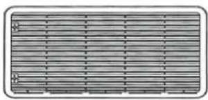
LS300
Gas flue kit
3776

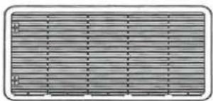
LS300
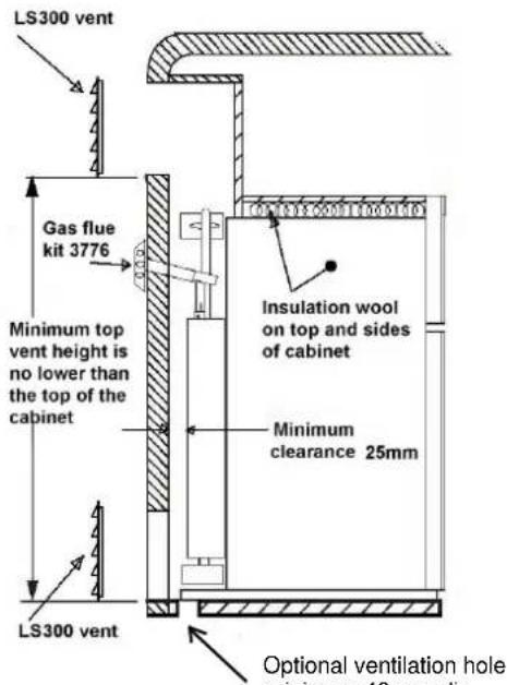
Optional ventilation hole minimum 40 mm dia
Option 2
Ventilation system not included
Roof Cap& roof base open ventilation area of 730 cm²
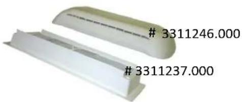
Gas flue kit # 3776

LS300 vent and frame cut out required 490mm x 249mm. Each vent has open area of 667 cm²

LS300

Optional ventilation hole minimum 40 mm dia
CLEARANCES
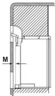
| Minimum clearances (mm) to combustible materials | |||
| Top 0 | G | ||
| Side 0 | K | ||
| Bottom | L | 0 | |
| Rear 25 | M | ||

TECHNICAL DATA
| RM2355 RM2455 RM2555 RM4605 RM4805 | |||||
| oVERALL DIMENSIOnSHeight (mm) 766 948 1104 1385 1544Width (mm) 556 632 632 632 632Depth incl. cooling unit (mm) 577 627 627 627 627 | |||||
| RECESS DIMENSIOnSHeight (mm) 756 928 1083 1365 1522Width (mm) 521 607 607 607 607Depth (mm) 542 610 610 610 610 | |||||
| CAPACTYGross (litres) 90 121 150 186 224 | |||||
| WEIGHT without packaging (kg) 20 39 44,5 56,5 58 | |||||
| ELECTRICAL DATA (watt)Input 240V 175 195 195 325 32512V 175 175 175 275 275 | |||||
| UNIVERSAL LP GAS DATAInput, max (MJ/h) | 1.10 1.16 1.16 1.66 1.66 | ||||
CONNECTING POINTS
Dimensions to connecting points (mm).
RM2355
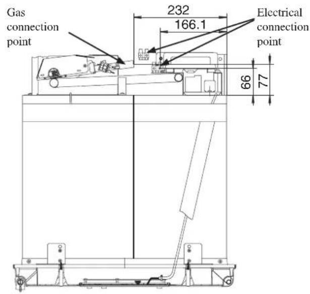
RM2455

RM2555
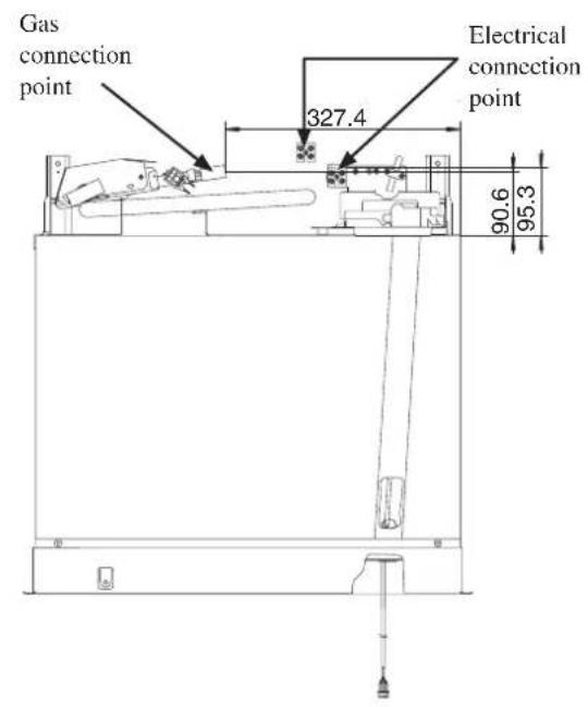
RM4605/RM4805

BUILDING-IN
The refrigerator must not be exposed to radiated heat from hot objects. Excessive heat irradiation impairs performance and leads to increased energy consumption. For this reason the refrigerator should be installed if possible not at the entrance side of the vehicle - normally orientated south and often with an awning which would impair the dispersion of heat and combustion gases from the ventilation openings.
It is not a good practice to install the refrigerator so that the vent openings are covered by the vehicle's entrance door when this is set open. This would reduce the ventilation airflow to the cooling unit and reduce refrigeration performance.
The refrigerator has to be installed in a substantial enclosure and must be level. For information about dimensions, see "TECHNICAL DATA".
The bottom of the enclosure must be horizontal and even so that the refrigerator can be easily pushed into place. It must be sturdy enough to carry the weight of the refrigerator.
A length of sealing strip is applied to the rear surface of the front frame for this purpose, see Fig. 8 / Fig. 9.
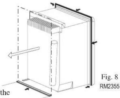
Apply a sealing strip to the foremost floor of the enclosure. The sealing should provide a complete isolation of the appliance's combustion system from the vehicle interior.
Make sure that there is a complete seal between the front frame of the refrigerator and the top, sides, and bottom of the enclosure.
Push the refrigerator into the recess until the sealing strip on the flange seals against the front of the recess, so that the cooling unit is completely sealed off against the interior of the vehicle.
Note: Be careful not to damage the sealing strip when the refrigerator is put in place.
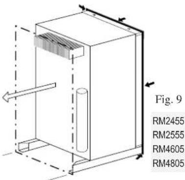
RM2455, RM2555, RM4605 & RM4805
A wood strip must be in place across the upper opening of the enclosure. The top frame of the refrigerator will be anchored to the wood strip with screws.

SECURING THE REFRIGERATOR
For the best cooling performance, when installing refrigerator model:
RM2355: The installer must block the space between the storage cabinet and the top of the refrigerator.
RM2455/RM2555/RM4605 & RM4805: The installer must block any space between the counter, storage area, or ceiling and the top of the refrigerator greater than 40 mm.
Otherwise, the heat will become trapped in this space, making the top of the refrigerator hot, thus reducing the efficiency of the unit.
After the refrigerator is put in place, ensuring a combustion seal at the front frame, the refrigerator is to be secured in the enclosure with screws. (These screws are not included.)
Failure to follow the sequence in securing the refrigerator in the enclosure can cause leakage between the frame and cabinet.
RM2355
The five screws should be installed in the following order:

Four screws installed through the front frame. 1. One screw installed in rear base. 2.

Fig. 11
RM2455, RM2555, RM4605 & RM4805
The six screws have to be installed in the following order:

Install two screws through the front base. 1. The refrigerator is provided with a lower front strip (shipped as a loose part) which is to be attached after the refrigerator is set into the cutout opening.
Install the lower front strip by sliding it under a) the bottom hinge plate and swing it into place.

(The hinge plate can be on the right or left side depending on the door swing.)
Secure the refrigerator and the lower front strip b) with two screws: One screw through the hinge, and on the opposite side and then, one screw through the lower front strip, see Fig. 13.

Install two screws in the top frame. 2.
Remove the top decoration panel. Open the a) door and gently push the tabs out of the hole in the hinge with a flat blade screwdriver, (both sides), see Fig. 14.

Carefully tilt the top decoration panel and lift b) up to remove from top frame. Be careful not to damage the circuit board and wires.
Install the two screws in the top frame. (The c) holes are accessible from underneath.)
Seal the opening for the screws with alumini-d) um tape.
Replace the top decoration panel. Be careful e) not to pinch the wires behind the panel. Make sure the tabs snap back into the holes in the hinge plate.
Install two screws in the rear base, see Fig. 15. 3.

Fig. 15
DRAIN WATER HOSE
A hole must be drilled through flooring, see Fig. 16 / 17.
The installer has to make sure that the hose does not kink when run through the floor. Seal around the hose that goes through the drilled hole.
If a longer hose than supplied is required to get the water to drain outside of the vehicle, the installer will have to supply the extra length of hose.


CONNECTIONS
UNIVERSAL LP GAS CONNECTION
The refrigerator is designed for operation on Universal LP gas.

Alternative gas types must not be used to operate this appliance!
The gas supply system must incorporate an approved gas pressure regulator to maintain a supply pressure of 2.75 kPa. The test point pressure must be 2.70 kPa. Check that this is stated on the data plate.

CAUTION
Check that the gas supplied to the refrigerator is at the correct pressure.
The gas installation and servicing must be carried out by an authorised person and conform to gas fitting regulations.
The appliance shall be installed in accordance with AS 5601-2 Gas Installations.
The gas supply pipe should be connected to the gas inlet connection at the rear of the refrigerator by means of a suitable threaded coupling.
The connection nipple is furnished with an ISO 7/1 - Rp 1/8 internal pipe thread connection.
In making the connection to the refrigerator, a union gas cock of an approved type for bottled gas must be incorporated in the supply line in a position that is readily accessible to the user. For eventual servicing purposes, the union should be on the outlet side of the cock and the pipe work should be positioned so as not to prevent the refrigerator from being readily withdrawn.
Before leaving, the installer should:
Check all connections for gas leaks with soap and water. • DO NOT use a naked flame for detecting leaks!
Ignite the burner to ensure correct operation of gas valve, burner and ignition.
Instruct the user on the correct method of operation. In case the appliance fails to operate correctly after all checks have been carried out, contact the authorized service provider in your area.
ELECTRICAL CONNECTION
The electrical installation must be carried out by authorized personnel.

For mains voltage operation, it is important that the circuit to and in the motorhome is effectively earthed.
The refrigerator is equipped with a three-prong (grounding) plug for your protection against shock hazards and should be plugged directly into a properly grounded three-prong receptacle. DO NOT cut off or remove the grounding prong from this plug!
If the supply cord is damaged, it must be replaced by the manufacturer, its service agent or similarly qualified persons in order to avoid a hazard.
230-240V SUPPLIES
Check that the voltage stated on the data plate is the same as the main voltage in use (230-240V).

Electrical leads must be routed and secured so that they cannot come into contact with hot or sharp parts of the refrigerator.
The cord should be routed to avoid direct contact with the burner cover, flue cover or any other components that could damage the cord insulation.

12V AND "D+" CONNECTION
The refrigerator is equipped with two terminals intended for connection to 12 volt.
RM2355, RM2455 and RM2555: One terminal is marked "CONNECT TO PERMANENT 12 VOLT DC HOUSE BATTERY" and the other "CONNECT TO VEHICLE 12 VOLT DC BATTERY", see Fig. 19.

RM4605 and RM4805: One terminal is marked "12V DC HOUSE" and the other "12V DC VEHICLE", see Fig. 20.


For a Motor Home the house battery and the vehicle battery may be the same battery. For a caravan the 12 volt connections can only be made to separate batteries.
CONNECTION MARKED "CONNECT TO VEHICLE 12 VOLT DC BATTERY" (RM2355/RM2455/RM2555) - OR - "12V DC VEHICLE" (RM4605/RM4805)
This connection supplies the 12V DC heating element.
The (+12V) and (-) poles have to be connected directly to the vehicle battery. Via a suitable connection to the tow vehicle when fitted to a caravan.
The (+12V) supply wire, connected to the terminal block (S) on the wiring diagrams, has to be fused according to the table below. Do not use the chassis for the return lead.
| Model Fuse size (A) | |
| RM2355/RM2455/RM2555 20 | |
| RM4605/RM4805 30 |
Cross-sections
The wires connected to this terminal must have the following minimum cross section area:
RM2355/RM2455/RM2555:
Maximum length of 8 metres from refrigerator to the battery. 6 mm² cross-section low voltage multi strand cable.
RM4605/RM4805:
Maximum length of 8 meters from refrigerator to the battery. 10 mm² cross-section low voltage multi strand cable.
Cable lengths > 8 meters will require a larger cross-sectional cable.
CONNECTION MARKED "CONNECT TO PERMANENT 12 VOLT DC HOUSE BATTERY" (RM2355/RM2455/RM2555) - OR - "12V DC HOUSE" (RM4605/RM4805)
This connection supplies the AES refrigerator control system and must not be interrupted at any time whilst using the refrigerator on 240 volt, gas, and 12 volt. This is a permanent 12 volt connection.
The (+12V) and (-) poles have to be connected directly to the permanent 12V DC house battery. Do not use the chassis for the return lead.
The 12V supply must not be connected to a voltage controller or similar device as the AES control system itself monitors the DC voltage.
The +12V must be permanently attached and must not be cut out when the ignition key is turned off. All connections should be screwed or soldered to keep voltage drop to a minimum.
Cross-sections
The wires connected to this terminal must have a minimum cross-section area of 1.5 mm².
D+ CONNECTION
The connection D+ (alternator) has to be connected to the corresponding outlet of the vehicles electrical system - either a 12V or a 24V DC alternator. The D+ connection accepts 24V. Please note that the refrigerator accepts 12V only. Do not connect the refrigerator to 24V!
This connection provides a signal to the refrigerators AES control system informing the control system when the vehicle engine is running.
The AES refrigerator can not select 12V as the energy source unless the vehicle engine is running.
Cross-sections
The D+ (alternator) is a signal cable and therefore 1-1.5 mm² is sufficient.
MOUNTING INSTRUCTIONS
REPOSITIONING THE HINGES
The refrigerator is equipped with reversible doors. A special door reversing kit must be used to reverse the doors. For further information, please contact your dealer.
MOUNTING THE DOOR PANEL (RM2355)
Door panels for RM2355 must be supplied by the manufacturer. This enables the manufacturer to match the door panel with the rest of the cabinetry inside the motor home or caravan.
Before starting the mounting work, read the instructions thoroughly.
Check that the panel dimensions are in compliance with those given in the following table:
| Dimensions (mm)(Thickness max 4 mm) | |
| Height Width | |
| 666±1 497±1 | |
We recommend that the panel is mounted before the refrigerator is installed in the enclosure. The lower decoration strip and parts bag are taped inside the door.
To mount the door panel, follow these steps:

Slide the panel from the bottom of the door into 1. the grooves on the vertical edges of the door.
Push the panel upwards. Take the two plastic panel 2. stops from the parts bag and put them in the two holes at the lower door frame.
Put the decoration strip across the door and fasten 3. with the screws from the parts bag.
REMOVING AND REPLACING THE SHELVES

Remove the shelf locks by inserting the tip of a flat 1. bladed screwdriver into the slot of the locks. Turn the screwdriver counterclockwise and then remove the shelf locks from the wire shelf.

Tilt the shelf to one side at an angle while pulling 2. forward.
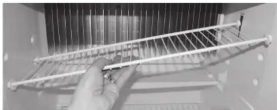
Reposition the shelf in the desired location. Insert 3. the ends of the wire shelf on the left-hand side and slide the shelf into the holes on the right-hand side.
Slide the plastic plugs into the holes of the wall. 4.
Snap the shelf locks onto the wire shelf. 5.

APPENDIX A - REARVIEW EQUIPMENT
RM2355
RM2455/RM2555
RM4605/RM4805
RM2355
385 08 85 4


CHASSIS GROUND
C—CIRCUIT BOARD DISPLAY
D-CIRCUIT BOARD POWER
E—ELECTRODE
F-FUSE 3A

I HEATER 12V DC
J—HEATER 230,240V AC
M-PROTECTIVE EARTH

REIGNITER BURNER

TERMINAL BLOCK

SOLENOID VALVE

TERMINAL BLOCK

TEST POINT

THERMISTOR

THERMOCOUPLE

TERMINAL BLOCK

1 BLACK
2 BROWN
3 RED
5 RED 4 YELLOW
4 BLUE 5 GREEN
5 GREEN 6 GREEN YELLOW
⑥ - GREEN, YELLOW
⑦ BLUE
⑧-GREY
⑨—WHITE
10 ORANGE
RM2455/RM2555
385 11 64 4
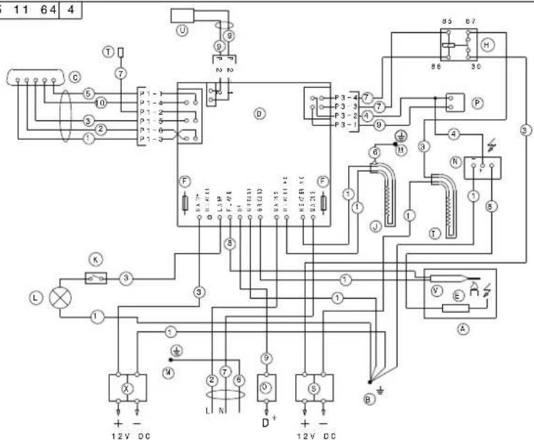

BURNER HOUSING
B-CHASSIS GROUND

CIRCUIT BOARD DISPLAY

CIRCUIT BOARD POWER

ELECTRODE

FUSE 3A
H—RELAY

HEATER 12V DC

HEATER 230,240V AC

SWITCH LAMP

LAMP

PROTECTIVE EARTH

REIGNITER

TERMINAL BLOCK

SOLENOID VALVE

TERMINAL BLOCK

TEST POINT

THERMISTOR

THERMOCOUPLE

TERMINAL BLOCK

BLACK
BROWN

RED

YELLOW

GREEN

GREEN/YELLOW

BLUE

GREY

WHITE
10 ORANGE
RM4605/RM4805

APPENDIX C - WORKING INSTRUCTIONS FOR THE GAS SAFETY SYSTEM
WORKING DIAGRAM
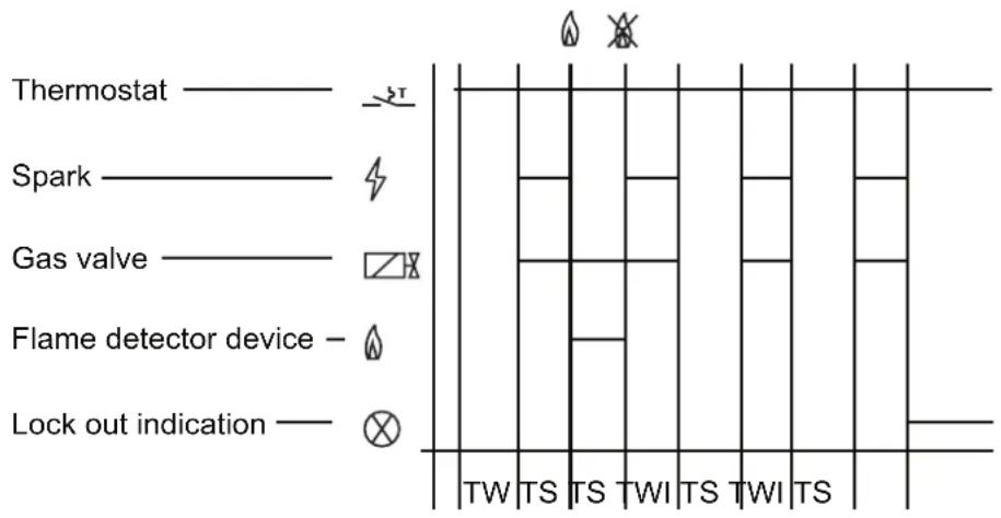
TECHNICAL SPECIFICATIONS
| Classification codes according to EN298 A-M-R-V-X-K | |
| Class of protection according to Low Voltage Directive IP-20 | |
| Waiting time / TW 8 s | |
| Safety time / TS 45 s | |
| Inter-waiting time / TWI 120 s | |
| Working temperature -20°C to +45°C | |
| Nominal working voltage* 12 - 13,8V DC | |
| Resistance to vibration according to EN60068-2-6:1995 |
*Functional approved at a voltage variation of +20% through -25%
- FOR YOUR SAFETY
- WARNING
- INSTALLATION
- OPERATING
- INSTRUCTIONS
- INTRODUCTION
- TRANSIT DAMAGE
- DATA PLATE
- CONTENTS
- OPERATING INSTRUCTIONS
- INSTALLATION INSTRUCTIONS
- CONTROL PANEL
- AES
- STARTING THE REFRIGERATOR
- WHILST MOBILE
- UNIVERSAL LP GAS OPERATION
- THE CONTROL ELECTRONICS AND THE IGNITER MUST HAVE 12V DC (BATTERY) SUPPLY TO OPERATE
- UNIVERSAL LP GAS TROUBLESHOOTING
- ABNORMAL OPERATION
- V OPERATION
- SWITCHING BETWEEN ENERGY SOURCES
- REGULATING THE TEMPERATURE
- TRAVEL CATCH
- USING THE REFRIGERATOR
- FOOD STORAGE
- ICE MAKING
- DEFROSTING
- CLEANING THE REFRIGERATOR
- AIRING POSITION CARD
- REPLACING THE BULB
- HEATING CABLE (RM4605 & RM4805)
- PRODUCT CARE - SOME USEFUL HINTS
- TROUBLESHOOTING
- IF THE REFRIGERATOR FAILS TO WORK
- THE REFRIGERATOR IS NOT COLD ENOUGH
- MAINTENANCE
- SERVICE AND SPARE PARTS
- GENERAL INFORMATION
- VENTILATION OF THE UNIT
- VENTILATION GRILLES
- SIDE VENTILATION
- ROOF VENTILATION
- VENTILATION HEIGHTS
- RECOMMENDED RM2355 VENTILATION SYSTEM
- OPTION
- LS
- CONNECTING POINTS
- BUILDING-IN
- RM2455, RM2555, RM4605 & RM
- SECURING THE REFRIGERATOR
- RM
- DRAIN WATER HOSE
- CONNECTIONS
- UNIVERSAL LP GAS CONNECTION
- CAUTION
- ELECTRICAL CONNECTION
- V SUPPLIES
- V AND "D+" CONNECTION
- CROSS-SECTIONS
- RM2355/RM2455/RM
- RM4605/RM
- CONNECTION MARKED "CONNECT TO PERMANENT 12 VOLT DC HOUSE BATTERY" (RM2355/RM2455/RM2555) - OR - "12V DC HOUSE" (RM4605/RM4805)
- D+ CONNECTION
- MOUNTING INSTRUCTIONS
- REPOSITIONING THE HINGES
- MOUNTING THE DOOR PANEL (RM2355)
- REMOVING AND REPLACING THE SHELVES
- APPENDIX A - REARVIEW EQUIPMENT
- RM2455/RM
- APPENDIX C - WORKING INSTRUCTIONS FOR THE GAS SAFETY SYSTEM
- WORKING DIAGRAM
- TECHNICAL SPECIFICATIONS
Brand : DOMETIC
Model : RM 2555
Category : Refrigerator