
T4PV - Remote control toy FUTABA - Free user manual and instructions
Find the device manual for free T4PV FUTABA in PDF.


| Product Type | Radio Control System |
| Model | T4PV |
| Brand | Futaba |
| Number of Channels | 4 |
| Frequency Band | 2.4GHz |
| Modulation | FHSS |
| Range | Up to 100 meters |
| Power Supply (Transmitter) | 4 x AA batteries (not included) |
| Power Supply (Receiver) | 4.8-6.0V NiMH or 2S LiPo |
| Dimensions (Transmitter) | 200 x 150 x 60 mm |
| Weight (Transmitter) | 350 g (without batteries) |
| Display | LCD screen |
| Steering Wheel Type | Pistol grip with adjustable spring tension |
| Throttle Trigger | Adjustable trigger |
| Trim Settings | Steering and throttle trim |
| Model Memory | 10 models |
| Failsafe Function | Yes, programmable |
| Maintenance | Keep clean and dry; store in a cool place; replace batteries when low |
| Safety Precautions | Do not use in rain; keep away from water; turn off when not in use; avoid eye contact with antenna |
| Spare Parts Availability | Contact Futaba or authorized dealers for replacement parts |
| Repairability | Service by qualified technicians only; consult manual for disassembly |
Frequently Asked Questions - T4PV FUTABA
User questions about T4PV FUTABA
0 question about this device. Answer the ones you know or ask your own.
Ask a new question about this device
Download the instructions for your Remote control toy in PDF format for free! Find your manual T4PV - FUTABA and take your electronic device back in hand. On this page are published all the documents necessary for the use of your device. T4PV by FUTABA.
USER MANUAL T4PV FUTABA
Telemetry System

INSTRUCTION MANUAL
1M23N31606
Futaba®
CE
Digital Proportional R/C System
Thank you for purchasing a Futaba 4PV-2.4GHz system. Before use, read this manual carefully in order to use it safely. After reading this manual, store it in a safe place.
IN NORTH AMERICA
Please feel free to contact the Futaba Service Center for assistance with operation and programming. Please be sure to regularly visit the 4PV Frequently Asked Questions web site at www.futaba-rc.com/faq/. This page includes extensive programming, use, set up and safety information on the 4PV radio system and is updated regularly. Any technical updates and US manual corrections will be available on this web page. If you do not find the answers to your questions there, please see the end of our F.A.Q. area for information on contacting us via e-mail for the most rapid and convenient response.
Don't you have Internet access? Internet access is available at no charge at most public libraries, schools, and other public resources. We find internet support to be a fabulous reference for many modelers as items can be printed and saved for future reference, and can be accessed at any hour of the day, night, weekend or holiday. If you do not wish to access the internet for information, however, don't worry. Our support teams are available Monday through Friday 8-5 Central time to assist you.
FOR SERVICE ONLY:
Futaba Service Center 3002 N. Apollo Drive, Suite 1 Champaign, IL 61822 Phone: 217-398-0007 www.futaba-rc.com/service.html E-mail: service@futaba-rc.com
FOR SUPPORT :
(PROGRAMMING AND USER QUESTIONS)
Please start here for answers to most questions:
www.futaba-rc.com/faq/
Fax: 217-398-7721
Phone: 217-398-8970 option 2
E-mail: support@futaba-rc.com
OUTSIDE NORTH AMERICA
Please contact the Futaba importer in your region of the world to assist you with any questions, problems or service needs.
Please recognize that all information in this manual, and all support availability, is based upon the systems sold in North America only. Products purchased elsewhere may vary. Always contact your region's support center for assistance.
Application, Export, and Modification
- This product may be used for models only. It is not intended for use in any application other than the control of models for hobby and recreational purposes.
- Exportation precautions:
(a) When this product is exported from the country of manufacture, its use is to be approved by the laws governing the country of destination for devices that emit radio frequencies. If this product is then re-exported to other countries, it may be subject to restrictions on such export. Prior approval of the appropriate government authorities may be required. If you
have purchased this product from an exporter outside your country, and not the authorized Futaba distributor in your country, please contact the seller immediately to determ such export regulations have been met.
(b) Use of this product with other than models may be restricted by Export and Trade Control Regulations, and an application for export approval must be submitted.
- Modification, adjustment, and replacement of parts: Futaba is not responsible for unauthorized modification, adjustment, and replacement of parts on this product. Any changes may void the warranty.
Compliance Information Statement (for U.S.A.)
This device, trade name Futaba Corporation, model number R304SB, complies with part 15 of the FCC Rules. Operation is subject to the following two conditions:
(1) This device may not cause harmful interference, and (2) This device must accept any interference received, including interference that may cause undesired operation.
(3)RF Exposure Information (SAR)
This device meets the government's requirements for exposure to radio waves.
This device is designed and manufactured not to exceed the emission limits for exposure to radio frequency (RF) energy set by the Federal Communications Commission of the U.S. Government.
The exposure standard employs a unit of measurement known as the Specific
Absorption Rate, or SAR. The SAR limit set by the FCC is 1.6 W/kg. Tests for SAR are conducted using standard operating positions accepted by the FCC with the EUT transmitting at the specified power level in different channels.
The FCC has granted an Equipment Authorization for this device with all reported SAR levels evaluated as in compliance with the FCC RF exposure guidelines. SAR information on this device is on file with the FCC and can be found under the Display Grant section of www.fcc.gov/eot/ea/fccid after searching on FCC ID: AZPT4PV-24G
The responsible party for the compliance of this device is:
Futaba Service Center
3002 N Apollo Drive Suite 1, Champaign, IL 61822 U.S.A
TEL (217)398-8970 or E-mail: support@futaba-rc.com (Support)
For Your Safety As Well As That Of Others ....8
Explanation Of Symbols 8
2.4GHz System Precautions 8
Receiver Mode Precautions 8
Operation Precautions ......9
NiMH/NiCd/LiFe Battery Handling Precautions ......10
Storage And Disposal Precautions ....10
Other Precautions ......11
Before Using 12
Features 12
Set Contents ......14
Transmitter T4PV ....15
Nomenclature....15
Battery Replacement Method (4 AA Size Batteries) ......16
Low Battery Alarm 16
When Using The Optional Battery ....17
When Exchanging The Optional Battery ....18
Power & Display Switch ....19
Display When Power Switch Is Turned On ....20
LCD Screen Contrast ....20
Power Off Forgotten Alarm 20
Steering Wheel And Throttle Trigger Operation ....21
Digital Trim & Grip Lever Operation 21
Mechanical ATL Adjustment 22
Wheel & Trigger Tension Adjustment 22
Trigger Slide Adjustment 23
Changing Wheel Position (optional parts) 24
Installing the accessory APA steering wheel offset adapter .....24
Using the optional angle spacer ....26
Non-telemetry LED (telemetry OFF sign) ......27
About Transmitter Antenna And Receiver....27
About The Transmitter Antenna ....27
Receiver Terminology ......28
Receiver Installation ....28
Installation 29
Receiver And Servo Connections ......29
Installation Safety Precautions ....30
Initial Set-Up 33
Preparations (Transmitter) 33
Receiver Type Check (RX MODE) 33
Receiver Type Change & How To Link 34
Throttle Mode Check ....37
Trims Initial Set-Up ....37
Function Map 39
Operation Of Screen 39
Calling The Menu Screen 39
Selecting Items On The Menu Screen 40
Value Of Each Function And Changing The Set Value .....40
Basic Menu Japanese Katakana Character Display ....41
Custom Menu 42
Custom Menu Displaying the custom menu screens ....42
Function List ....43
Direct Model Call 44
Functions 45
Model "MODEL" 45
Model Menu Display 45
Model Selection "SELECT" 46
Model memory call
Model Copy "COPY" 47
Model memory copy.
Model Reset "RESET" 48
Model memory reset
Model Name "MDL NAME" 49
Model memory name & User name, set/modify
Servo Reverse "REVERSE" 50
Servo operation reversing
Subtrim "SUBTRIM" 51
Servo center position fine adjustment
End Point Adjuster "END POINT" 52
End point adjustment
Fail Safe Function "FAIL SAFE"....55
Fail safe, battery fail safe function
Exponential Adjustment "EXP"......57
Steering operation curve / Throttle curve adjustment.
Servo Speed "SPEED" 60
Steering/ Throttle servo delay adjustment
Throttle Acceleration "TH ACCEL" 63
Function which adjusts the movement characteristic from the throttle neutral position
For Your Safety As Well As That Of Others
Before Using
Installation
Initial Set-Up
Function Map
Functions
Reference
A.B.S. Function "TH A.B.S" 65
Pulse brake
Steering Dual Rate/ Throttle ATL "D/R ATL" 69
Steering D/R, Throttle ATL Rate
Select Trim Dial Function "TRIM DIAL"....70
Selection of functions operated by digital trim and dial
Select Switch Function "SWITCH" 72
Selection of functions operated by switch
Steering Mixing "STR MIX"....74
Twin servo steering system
Brake Mixing "BRAKE MIX" 76
Front and rear independent brake control for 1/5 GP car, etc.
Programmable Mixing "PROG MIX" 78
Programmable mixing between arbitrary channels
4WS Mixing "4WS" 80
Special mixing used with Crawler and other 4WS type vehicles
Dual ESC Mixing "DUAL ESC" 82
Special mixing used with Crawler and other 4WD type vehicles
Gyro Mixing "GYRO MIX" 84
Use to set the Futaba car rate gyro
CPS Mixing "CPS MIX" 86
Controls the Futaba CPS-1 channel power switch
Throttle Mode "TH MODE" 88
Throttle Servo Neutral Position "SXNT" 88
Throttle servo forward and brake operation proportion setting
Idle-Up "IDLUP" 89
Idle up at engine start
Neutral Brake "NTBRK" 90
Neutral brake function
Throttle Off (Engine Cut) "THOFF" 91
Engine cut off by switch
Channel 3/4 "CH3/CH4" 92
Channel 3/4 Position
S.BUS Link Function "SX LINK" 93
Special function, Futaba S.BUS/S.BUS2 servo parameter setup
ESC Link Function "MC LINK"......97
Special function, Futaba ESC (MC940CR, MC960CR, MC950CR, MC851C, MC602C,
MC402CR, etc.)
Data Transfer "MDL TRANS" 105
The T4PV model memory data to another T4PV
Timer Function "TIMER" 107
Up, Fuel down, or lap timer
Lap List "LAP LIST" 113
Lap timer data check
Telemetry "TELEMETRY" 114
Connection diagram ......115
Telemetry Function ON/OFF 115
Telemetry Sensor Setting 117
Telemetry Sensor Setting 119
Log Setting, Start/ Stop 120
Log Data List ....122
System Functions "SYSTEM" 123
Liquid crystal screen contrast adjustment
Liquid crystal screen backlighting display mode setup
Backlight display time setup
Backlight brightness setup
Battery type setting
Buzzer sound tone adjustment
The power off forgotten alarm setting
Item which displays the basic menu screen in katakana characters for Japanese use
HOME screen display mode setting
Adjuster "ADJUSTER" 127
Steering wheel and throttle trigger correction
Reference 129
Ratings ......129
Warning Displays 130
Optional Parts 131
When requesting repair ....133
For Your Safety As Well As That Of Others
Before Using
Installation
Initial Set-Up
Function Map
Functions
Reference
Use this product in a safe manner. Please observe the following safety precautions at all times.
Explanation Of Symbols
For safety's sake, pay special attention whenever you see the marks shown here.
Symbols
Explanation

Danger
Indicates a procedure which could lead to a dangerous situation and may cause death or serious injury if ignored and not performed properly.

Warning
Indicates procedures which may lead to dangerous situations and could cause death or serious injury as well as superficial injury and physical damage.

Caution
Indicates procedures that may not cause serious injury, but could lead to physical damage.
Symbols:
∅ : Prohibited
! : Mandatory
2.4GHz System Precautions

Warning
Special attention should be paid before turning on the system while other cars are running or other airplanes are flying because the 2.4GHz RC system could potentially affect them.
! Be sure to set the Fail Safe function.
Receiver Mode Precautions

Caution
When using the T4PV in the T-FHSS (HIGH) and S-FHSS (HIGH) mode, always use it under the following conditions:
Servos :Futaba digital servo (including BLS Series brushless servos)
Receiver's battery :Matched to the ratings of the receiver and connected digital servo (dry cell battery cannot be used). Transmitter mode : RX MODE (See p.33-34 for setting method.)
Under other conditions, the set will not operate, or the specified performance will not be displayed even if it operates. In addition, it may cause servo trouble. Futaba will not be responsible for damage, etc. caused by combination with the products of other companies.
In addition, the FSU Fail Safe Unit cannot be used because the system is different. Use the fail safe function of the transmitter.
When using analog servos, always switch the T4PV servo response to the "NORM" mode.
Transmitter mode:"T-FHSS (NORM)" and "S-FHSS (NORM)" mode (See p.33-34 for setting method.) Receiver's battery :Matched to the ratings of the receiver and connected servo (dry cell battery cannot be used).
The set cannot operate in the "HIGH" mode. Operation in this mode will cause trouble with the servo and other equipment. Digital servos (including BLS Series brushless servos) can also be used in the "NORM" mode.
Operation Precautions

Warning
Do not operate outdoors on rainy days, run through puddles of water or use when visibility is limited.
Should any type of moisture (water or snow) enter any component of the system, erratic operation and loss of control may occur.
Do not operate in the following places.
-Near other sites where other radio control activity may occur.
-Near people or roads.
-On any pond when passenger boats are present.
-Near high tension power lines or communication broadcasting antennas.
Interference could cause loss of control. Improper installation of your Radio Control System in your model could result in serious injury.
Do not operate this R/C system when you are tired, not feeling well or under the influence of alcohol or drugs.
Your judgment is impaired and could result in a dangerous situation that may cause serious injury to yourself as well as others.
Do not touch the engine, motor, speed control or any part of the model that will generate heat while the model is operating or immediately after its use.
These parts may be very hot and can cause serious burns.
Always perform an operating range check prior to use.
Problems with the radio control system as well as improper installation in a model could cause loss of control. (Simple range test method)
Have a friend hold the model, or clamp it down or place it where the wheels or prop cannot come in contact with any object. Walk away and check to see if the servos follow the movement of the controls on the transmitter. Should you notice any abnormal operation, do not operate the model. Also check to be sure the model memory matches the model in use.
! Turning on the power switches.
Always check the throttle trigger on the transmitter to be sure it is at the neutral position.
-
Turn on the transmitter power switch.
-
Turn on the receiver or speed control power switch.
Turning off the power switches
Always be sure the engine is not running or the motor is stopped.
- Turn off the receiver or speed control power switch.
- Then turn off the transmitter power switch.
If the power switches are turned off in the opposite order, the model may unexpectedly run out of control and cause a very dangerous situation.
When making adjustments to the model, do so with the engine not running or the motor disconnected.
You may unexpectedly lose control and create a dangerous situation.
Before running (cruising), check the fail safe function.
Check Method: Before starting the engine, check the fail safe function as follows:
1) Turn on the transmitter and receiver power switches.
2) Wait at least one minute, then turn off the transmitter power switch. (The transmitter automatically transfers the fail safe data to the receiver every minute.)
3) Check if the fail safe function moves the servos to the preset position when reception fails.
The fail safe function is a safety feature that minimizes set damage by moving the servos to a preset position when reception fails. However, if set to a dangerous position, it has the opposite effect. When the reverse function was used to change the operating direction of a servo, the fail safe function must be reset.
Setting example: Throttle idle or brake position
NiMH / NiCd / LiFe Battery Handling Precautions
(Only when NiMH/NiCd /LiFe batteries are used)

Warning
Never plug the charger into an outlet of other than the indicated voltage.
Plugging the charger into the wrong outlet could result in an explosion or fire.
Never insert or remove the charger while your hands are wet.
You may get an electric shock.
Do not use the T4PV transmitter's battery as the receiver's battery.
Since the transmitter's battery has an overload protection circuit, the output power will be shut down when the high current load is applied. This may result in runaway or fatal crash.
Always check to be sure your batteries have been charged prior to operating the model.
Should the battery go dead while the model is operating, loss of control will occur and create a very dangerous situation.
To recharge the transmitter battery, use the special charger made for this purpose.
Overcharging could cause the battery to overheat, leak or explode. This may lead to fire, burns, loss of sight and many other types of injuries.

Caution
Do not use commercial AA size NiCd and NiMH batteries.
Quick charging may cause the battery contacts to overheat and damage the battery holder.
Do not short circuit the battery terminals.
A short circuit across the battery terminals may cause abnormal heating, fire and burns.
Do not drop the battery or expose it to strong shocks or vibrations.
The battery may short circuit and overheat; electrolyte may leak out and cause burns or chemical damage.
When the model is not being used, always remove or disconnect the battery.
Leaving the battery connected could create a dangerous situation if someone accidentally turns on the receiver power switch. Loss of control could occur.
Always keep the charger disconnected from the outlet while it is not in use.
Storage And Disposal Precautions

Warning
Do not leave the radio system or models within the reach of small children.
A small child may accidentally operate the system. This could cause a dangerous situation and injuries. NiCd batteries can be very dangerous when mishandled and cause chemical damage.
Do not throw NiMH/NiCd/LiFe batteries into a fire. Do not expose batteries to extreme heat. Also do not disassemble or modify a battery pack.
Overheating and breakage will cause the electrolyte to leak from the cells and cause skin burns, loss of sight, and other injuries.
When the system will not be used for any length of time, store the system with NiMH/NiCd batteries in a discharged state. Be sure to recharge the batteries prior to the next time the system is used.
If the batteries are repeatedly recharged in a slightly discharged state, the memory effect of the NiMH/NiCd battery may considerably reduce the capacity. A reduction in operating time will occur even when the batteries are charged for the recommended time. (After discharge to 1cell E.V.=1V)
When a LiFe battery pack will not be used for a long time, to prevent it from deteriorating we recommend that it be kept in about the half capacity state instead of fully charged. Also be careful that the battery does not enter the over-discharged state due to self-discharge.
Periodically (about every 3 months) charge the battery.
The electrolyte in NiCd/NiMH batteries is a strong alkali. Should you get even the smallest amount of the electrolyte in your eyes, DO NOT RUB. Wash immediately with water, and seek medical attention at once. The electrolyte can cause blindness. If electrolyte comes in contact with your skin or clothes, wash with water immediately.

Warning
Do not store your R/C system in the following places.
- Where it is extremely hot or cold.
- Where the system will be exposed to direct sunlight.
- Where the humidity is high.
- Where vibration is prevalent.
- Where dust is prevalent.
- Where the system would be exposed to steam and condensation.
Storing your R/C system under adverse conditions could cause deformation and numerous problems with operation.
If the system will not be used for a long period of time, remove the batteries from the transmitter and model and store in a cool, dry place.
If the batteries are left in the transmitter, electrolyte may leak and damage the transmitter. This applies to the model also. Remove the batteries from it also to prevent damage.
A used battery is a valuable resource. Insulate the battery terminals and dispose of the battery by taking it to a battery recycling center.
Other Precautions

Caution
Do not expose plastic parts to fuel, motor spray, waste oil or exhaust.
The fuel, motor spray, waste oil and exhaust will penetrate and damage the plastic.
Always use only genuine Futaba transmitters, receivers, servos, ESCs (electronic speed controls), NiMH/NiCd/LiFe batteries and other optional accessories.
Futaba will not be responsible for problems caused by the use of other than genuine Futaba parts. Use the parts specified in the instruction manual and catalog.
Features
-Telemetry system
The T4PV transmitter has adopted the newly developed bidirectional communication system "T-FHSS".
-2.4GHzSS (Spread Spectrum) radio communication system
Frequency channel setting is unnecessary: Channel shifting takes place within the 2.4GHz band automatically. This system minimizes the interference from other 2.4GHz systems.
-Display switch
Display switch allows function setup without transmitting.
-Model memory for 40 models
Model names can use up to 10 letters, numbers, and symbols, so that logical names may be used. A model memory with different setups can be created by using the model copy function.
-4 axis Jog button.
The (JOG) button can be operated in 4 directions: up, down, left, and right.
-ESC-Link function (MC-LINK)
This dedicated function allows you set up the Link software so that your T4PV can control variable frequency and other data changes in Futaba speed controllers (ESCs): MC950CR, MC850C, MC851C, MC602C, MC402CR, etc.
-S.BUS servo
This is a special function that allows setting of the parameters of our S.BUS servo whose settings are changed by using PC Link software.
-Steering mixing
Smooth cornering is possible by independent left and right steering servo setting.
-Brake mixing for large cars (BRAKE)
Brake mixing of the front and rear wheels of 1/5 GP and other large cars can be adjusted independently.
-Gyro mixing (GYRO MIX)
The sensitivity of Futaba car rate gyros can be adjusted from the T4PV.
-4WS mixing for crawlers and other 4WS type (4WS)
This function can be used with crawlers and other 4WS type vehicles.
-Dual ESCs mixing for crawlers cars (DUAL ESC)
ESCs at the front and rear are controlled independently.
-CPS-1 mixing (CPS MIX)
LED lighting and flashing control using our CPS-1 channel power switch can be matched to steering and throttle operation by switch only.
-Anti-skid braking system (TH A.B.S)
This function applies the brakes so that the tires of GP cars, etc. do not lose their grip on the road even when braking at corners.
-Throttle acceleration (ACCEL)
GP cars have a time lag before the clutch and brakes become effective.
The throttle acceleration function reduces this time lag.
-Throttle speed (SPEED)
Sudden trigger operation on a slippery road surface will only cause the tires to spin and the model to not accelerate smoothly. By setting the throttle speed function, operation can be performed smoothly and easily. It also suppresses battery consumption.
-Steering speed (SPEED)
When you sense that the steering servo is too fast, etc., the servo operating speed (direction that suppresses the maximum speed) can be adjusted.
-Racing timer (TIMER)
The lap timer can record 100 lap times and total time. The timer can also be started automatically by trigger operation. The race time and audible alarm can be set.
Re-/fueling time are indicated by an audible alarm. An up timer is also provided.
-Function select switch (SWITCH)/ dial function (TRIM DIAL)
This assigns functions to 2 switches and dials (digital trim, digital dial). The step amount and operating direction can also be adjusted. Trim positioning at each model call is unnecessary because all the dials are digital.
-Trigger position can be changed
The position of the throttle trigger can be moved forward and backward.
-Tension adjustment function
The tension of the steering wheel & throttle trigger springs can be adjusted from the outside.
-Mechanical ATL Adjustment
Make this adjustment when you want to decrease the total travel of the brake (push) side of the throttle trigger.
Set Contents
After opening the box, first check if the contents conform to the following. The contents depend on the set as shown below.
| Transmitter T4PV | |
| Receiver R304SB | |
| Miscellaneous | Dry battery holder*Installed in transmitter. |
| Mini screwdriver* It is used for R304SB. | |
| Instruction manual | |
- If any of the set contents are missing, or you have any questions, please contact your dealer.

Caution
When using the T4PV in the T-FHSS (HIGH) and S-FHSS (HIGH) mode, always use it under the following conditions:
Servos :Futaba digital servo (including BLS Series brushless servos)
Receiver's battery :Matched to the ratings of the receiver and connected digital servo (dry cell battery cannot be used).
Transmitter mode : RX MODE (See page 33-34 for setting method.)
Under other conditions, the set will not operate, or the specified performance will not be displayed even if it operates. In addition, it may cause servo trouble. Futaba will not be responsible for damage, etc. caused by combination with the products of other companies.
In addition, the FSU Fail Safe Unit cannot be used because the system is different. Use the fail safe function of the transmitter.
When using analog servos, always switch the T4PV servo response to the "NORM" mode.
Transmitter mode:"T-FHSS (NORM)" and "S-FHSS (NORM)" mode (See page 33-34 for setting method.) Receiver's battery :Matched to the ratings of the receiver and connected servo (dry cell battery cannot be used).
The set cannot operate in the "HIGH" mode. Operation in this mode will cause trouble with the servo and other equipment.
Digital servos (including BLS Series brushless servos) can also be used in the "NORM" mode.
Always use only genuine Futaba transmitters, receivers, servos, ESCs (electronic speed controls), NiMH, NiCd, LiFe batteries and other optional accessories.
Futaba will not be responsible for problems caused by the use of other than Futaba genuine parts. Use the parts specified in the instruction manual and catalog.
Transmitter T4PV
Nomenclature

*The switches, dial, and trimmers in the figure are shown in the initial setting position.
Battery Replacement Method (4 AA Size Batteries)
Load the four batteries in accordance with the polarity markings on the battery holder.
Battery Replacement Method
1 Remove the battery cover from the transmitter by sliding it in the direction of the arrow in the figure.
2 Remove the used batteries.
Caution
If you remove the dry cell battery box from the transmitter, replace it carefully with the wiring on the same side as before. Reinstalling the battery box in the opposite direction could cause the wires to be disconnected.
3 Load the new AA size batteries. Pay very close attention to the polarity markings and reinsert accordingly.
4 Slide the battery cover back onto the case.
Check:
Turn the power switch on the transmitter to the ON position. Check the battery voltage display on the LCD screen. If the voltage is low, check the batteries for insufficient contact in the case or incorrect battery polarity.

Slide battery cover while pressing here.

Disposal of the Dry Cell Batteries:
The method to dispose of used dry cell batteries depends on the area in which you reside. Dispose of the batteries in accordance with the regulations for your area.
Caution
Never try to recharge a dry cell battery.
The transmitter may be damaged or the battery electrolyte may leak or the battery may break.
! Insert the batteries in the correct polarity.
If the polarity is incorrect, the transmitter may be damaged.
When the transmitter is not in use, remove the batteries.
If the battery electrolyte leaks, wipe off the case and contacts.
Do not use commercial AA size NiCd and NiMH batteries.
Quick charging may cause the battery contacts to overheat and damage the battery holder.

Use prohibited
Low Battery Alarm
If the transmitter battery voltage drops below the usable range, an audible alarm will sound and "☐" mark will be displayed on the LCD screen. (For details, see page 130.) Because the low battery alarm voltage of a dry cell battery is different from that of a rechargeable battery pack (genuine Futaba option), the type of power source used must be selected using the system setting (page 123).
Warning
When a low battery alarm is generated, cease operation immediately and retrieve the model. If the battery goes dead while in operation, you will lose control of the model.
When Using The Optional Battery
When using an optional rechargeable battery, replace the battery as described below.
-Always use the optional FT2F1700B, FT2F2100B or HT5F-1800B rechargeable battery.
-The type of power source used must be selected through the system setting (page 123).
-When the transmitter will not be used for a long time, remove the battery.
Battery Replacement Method
1 Refer to the previous description and remove the transmitter battery cover.

Slide battery cover while pressing here.

Before Using
2 After removing the dry cell battery box from the transmitter, disconnect the connector.
Caution
If you remove the dry cell battery box from the transmitter, replace it carefully with the wiring on the same side as before. Reinstalling the battery box in the opposite direction could cause the wires to be disconnected.

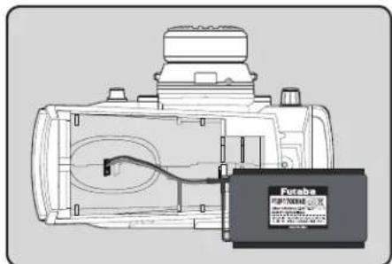
3 Insert the connector of the new battery and load the new battery into the transmitter.
4 Finish by installing the battery cover.

Caution
When closing the battery cover, be careful that the battery cover does not pinch the battery lead wires.
Shorting of the battery lead wires may lead to fire and abnormal heating and cause burns or fire disaster.
Charging A NiMH Battery
(Example: When using the HT5F1800B with the special charger)
1 Plug the transmitter cord of the special charger into the charging jack on the rear of the transmitter.
2 Plug the charger into an AC outlet.
3 Check that the charging LED lights.
The charging time when charging the HIT5F1800B battery with the optional special charger is approximately 15 hours. However, when the battery has not been used for some time, repeat charging 2 or 3 times to activate the battery.
Over current protection
The transmitter charging circuit is equipped with an over current protection circuit (1.0A). If the battery is charged with a quick charger for other than digital proportional R/C sets, it may not be fully charged.
Charging A LiFe Battery
(Example: When using the FT2F1700B/2100B with the special charger)
1 Remove the battery cover.
2 Disconnect the battery from the T4PV.
3 Balance charging cannot be done through the transmitter. You must remove the LiFe battery to do this charge.
LiFe battery is removed from transmitter.


Charge the optional FT2F1700B/2100B (LiFe) battery with the special charger in accordance with the instruction manual supplied.
When the LiFe battery will not be used for a long time, to prevent it from deteriorating we recommend that it be kept in about the half capacity state instead of fully charged. Also be careful that the battery does not enter the overdischarged state due to self-discharge. Periodically (about every 3 months) charge the battery. In addition, always remove the battery from the model and store it in a dry, cool place (15°C\~25°C).

Balance charging connector for LiFe battery charger.
Warning
Make sure not to peel off the battery film, or make any scratch by a cutter knife or the sharp edges of metal components.
Make sure not to soak or get the battery wet with water or seawater.
Make sure not to use a deformed or swollen battery.
There is a risk of explosion or fire, which is very dangerous.

Warning
Never plug it into an outlet having other than the indicated voltage.
Plugging the charger into the wrong outlet could result in an explosion or fire.
Do not insert and remove the charger when your hands are wet.
It may cause an electric shock.
Always use the special charger or a quick charger for digital proportional R/C sets to charge a digital proportional R/C set battery.
Overcharging a NiMH battery can result in burns, fire, injuries, or loss of sight due to overheating, breakage, or electrolyte leakage.

Caution
Do not plug the charger to the charging jack, if the battery is not connected to the transmitter. The transmitter may be damaged.
When the charger is not in use, disconnect it from the AC outlet.
Do this to prevent accidents and to avoid overheating.
Power & Display Switch
The power switch and display switch are push switches.
When the power switch (PWR) is held down, operation starts by transmitting radio waves. When the display switch is held down, the transmitter side data can be checked and set.
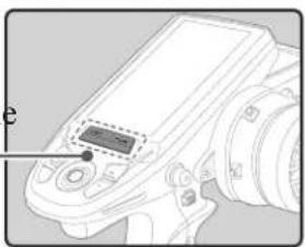
Power & Display Switch

DSP
Blinking at the same time the LED fl ashes "DISP MODE". The transmitter beeps in the Display mode.
Radio waves are not being transmitted.




OFF
When the power is turned off, if the power switch or display switch is held down, the power is turned off. If both switches are pressed simultaneously, the power is turned off quickly.


PWR

Radio waves are being transmitted.

When you do not run, turn OFFIt cannot operate. It can operate.
![graph TD A["Power switch turned on"] --> B["Beep confirmation sound is generated and the HOME screen shown below appears."] B --> C["Timer"] C --> D["Model number"] D --> E["Model name (10 characters)"] E --> F["The current receiver mode is displayed."] F --> G["Telemetry data"] G --> H["TM 00:00.00…](/content/2026/07/1455774/images/e3e9a82e850d54caa332fdc4c0a8a48b60416db794db73db0d41f35589ad33f1.jpg)
LCD Screen Contrast
The LCD screen contrast can be adjusted. (For more information, see page 123.)
Caution
Do not adjust the contrast so that the LCD is too bright or too dark.
When the display cannot be read due to a temperature change, data cannot be set.
Power Off Forgotten Alarm & Auto Power Off
When the steering wheel, throttle trigger, push switch, or edit button are not operated for 10 minutes (default), an alarm sound NOT OPERATED FOR A LONG TIME" is displayed on the LCD screen.
When the steering wheel, throttle trigger, push switch, or edit button are operated, the alarm is reset. If the alarm is not reset, the auto power off function will automatically turn off the power after 5 minutes. If the system is not to be used, turn off the power.
The function can be deactivated at the system menu (p.123).

Steering Wheel And Throttle Trigger Operation
(CH1: Steering wheel, CH2: Throttle trigger)
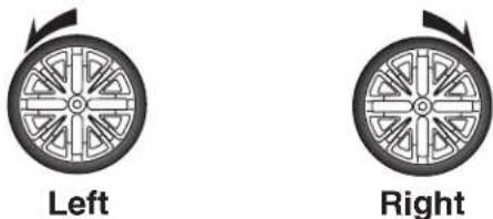
Steering Wheel Function: Turns the model right or left.
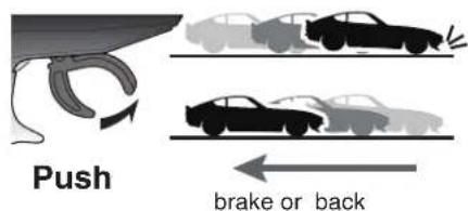
Throttle Trigger Function: Controls the speed of the model as well as the direction of travel - forward or reverse.
Throttle trigger function Steering wheel function


Digital Trim Operation
(Initial settings: DT1: Steering trim, DT2: Throttle trim, DT3: Channel 3, DT4: Channel 4, DT5: Steering D/R, DT6: ATL-Brake rate)
Operating by the trim: Push the trim lever to the left or right (up or down). The current position is displayed on the LCD screen.
DT2 DT1 DT5
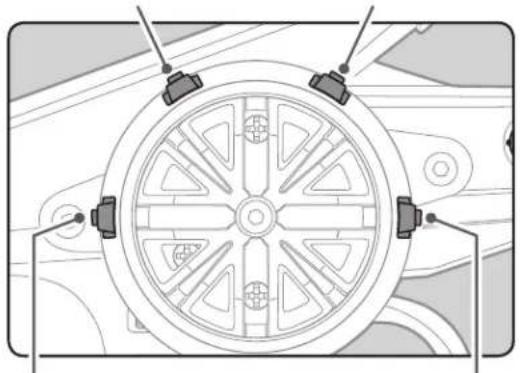
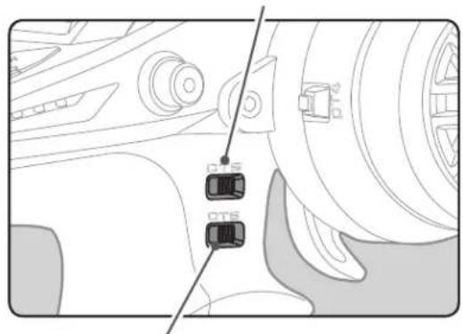
DT3 DT6DT4
• Each step is indicated by a tone.
- When the trim exceeds the maximum trim adjustment range, the beep will change and the servo will not move any farther.
- Steering D/R: The steering left and right servo travels are adjusted simultaneously.
- ATL: Decreases the set value when the braking effect is strong and increases the set value when the braking effect is weak.
Steering And Throttle Trim Operation
With the center trim feature, trim adjustments have effect on the maximum servo travel. This prevents the linkages from binding when adjustments are made.

Mechanical ATL Adjustment
Make this adjustment when you want to decrease the stroke of the brake (back) side of the throttle trigger to your preferences.
Adjustment
1 Using a 1.5mm hex wrench, adjust the trigger brake (reverse) stroke. (The screw moves the throttle trigger stopper.)
- When the screw is turned clockwise, the stroke becomes narrower. Adjust the stroke while watching the screw.
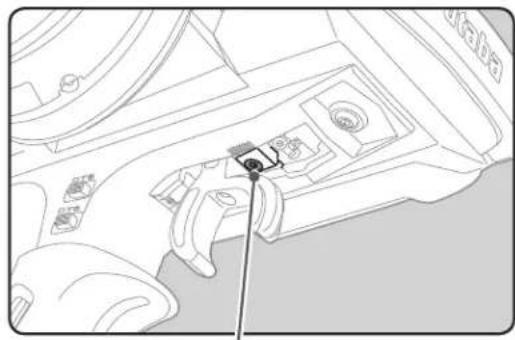
Mechanical ATL adjusting screw
Note:
Once you have changed the mechanical stroke on the brake side, be sure to adjust the scale of the throttle channel accordingly by using the "Adjuster Function" (page 127).
Due to this change, you also need to adjust in most cases the travel of the throttle servo by using "End Point Adjuster".
Wheel & Trigger Tension Adjustment
Make this adjustment when you want to change the wheel or trigger spring's tension.
Adjustment
1 Using a 1.5mm hex wrench, adjust the spring tension of the wheel or throttle by turning the screw shown in the figure.
The wheel side is inside the adjustment hole.
- The spring is set to the weakest tension at the factory.
- When the adjusting screw is turned clockwise, the spring tension increases.

Wheel tension
adjusting screw
Trigger tension
adjusting screw
Note:
The adjustment range is up to 7 to 8 turns from the fully tightened (strongest) position. If turned farther than this, the adjusting screw may fall out.
Trigger Slide Adjustment
The throttle trigger position can be moved forward and backward.
Adjustment
1 Using a 2.0mm hex wrench, loosen the trigger slide mounting screw by turning it slightly counterclockwise.
• Always loosen this screw.
Note:
If the trigger slide screw is turned too much, the screw may fall out.
2 Adjust the trigger slide position within the marked range.
3 Retighten the mounting screw loosened at step 1 and fasten the trigger slide.
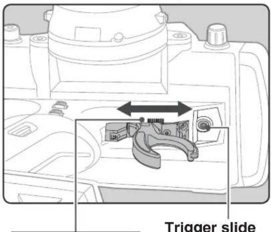
Adjust so that the bottom ▲ mark does not exceed the top marking line.
Trigger slide
mounting screw

Changing Wheel Position (optional parts)
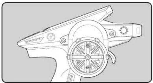
The wheel position can be offset by using the optional APA wheel position offset adapter.
Installing the accessory APA steering wheel offset adapter
- Three 2.6 × 10 mm and 2.6 × 19 mm tapping screws are supplied with the adapter APA.
- Obtain 2.5mm hex wrench./ Remove the battery.
- The length of the screws used at each part differs. When reassembling the steering wheel unit, always use the specified screws.
1 Remove the 2 steering wheel unit mounting screws.
(Using a 2.5 mm hex wrench.)
-Remove the 2 mounting screws completely from the transmitter body.

2 Gently remove the steering unit, without pulling excessively on the wiring.
-Remove the steering wheel unit slowly so that the internal wiring is not pulled unreasonably.
Remove the connector from the PC board. -Remove from the PC board while pressing both sides of the connector.
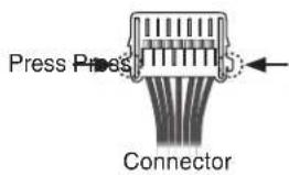

3 Using a Phillips screwdriver, remove the 4 screws (2.6x15mm tapping screw) mounting the wheel unit and base parts.


4 Pass the wiring from the steering wheel unit through the hole in the APA as shown in the figure.
Adapter APA

5 Using a Phillips screwdriver fasten the wheel unit and APA at the desired angle using the 2.6x19mm tapping screws. Be careful that the screw length is correct. Be careful that the wiring does not get pinched. The angle can be adjusted, but check the marking point on the wheel unit and install the screws.
-Four 2.6x19 mm tapping screws are supplied with the APA. -Screws can be installed at 4 places, but installation at 4 places may be impossible due to the wheel unit mounting angle.

6 Using a Phillips screwdriver fasten the base parts and APA. Use the 2.6x10mm tapping screws. Next, install the APA rear cover. Be careful that the length of the screws is correct.
-Three 2.6x10 mm tapping screws are supplied with the APA.
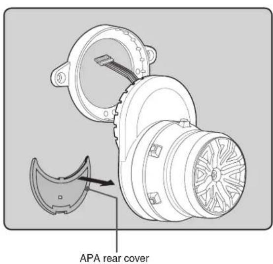
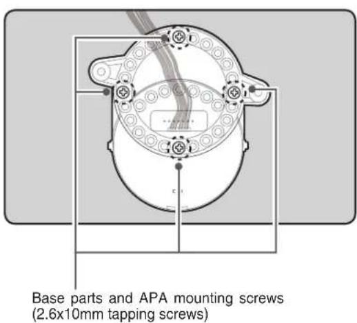
7 Install the assembled steering wheel unit to the transmitter body.
-Install slowly so that the wiring is not pinched.

8 Install the assembled steering wheel unit and APA to the transmitter using the screw (3.0x12mm cap screw) supplied.
(Using a 2.5 mm hex wrench.)
Steering wheel unit mounting screws

Using the optional angle spacer
The wheel mounting angle can be changed by using the optional angle spacer.
- Three 2.6x10mm tapping screws are supplied with the angle spacer.
- When using and not using the APA, refer to the following installation.
- Obtain a Phillips screwdriver. Be careful of the length of the screws used.
• The wheel is assembled by passing the screws through each part.


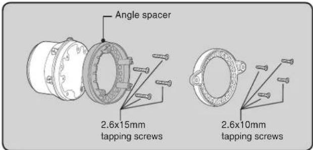


Non-telemetry LED (telemetry OFF sign)
When the telemetry function is inhibited by race regulations, a special LED lights when the telemetry function is OFF to confirm that the telemetry function is not operating.

About Transmitter Antenna and Receiver
About The Transmitter Antenna

Antenna Moving Range
If the antenna is set to the 90° vertical position, the range of the radio waves may be greater than in the horizontal position. (Different depending on the conditions.)


Warning
☒ Please do not grasp the transmitter's antenna while driving.
Doing so may degrade the quality of the RF transmission to the model.
The antenna position can be changed in the range as shown in fi gure. However, please do not apply unnecessary force or shock.
The internal cable may be damaged; thus transmitting distance decreases and it may cause malfunction.
A small glitch may occur if the transmitter antenna is brought close to servos, ESCs or other peripheral devices. This is not a serious issue, but keep it in mind (especially during setup).
Receiver Terminology
![graph LR A["Antenna"] --> B["Coaxial cable"] B --> C["Tactile switch/ LED"] C --> D["Futaba"] D --> E["R3D4SB 4/3/2/1 3/2/1 3/2/1 3/2/1"] style A fill:#f9f,stroke:#333 style B fill:#f9f,stroke:#333 style C fill:#ccf,stroke:#333 style D fill:#cfc,stroke:#333 style E fill:#fcc,stroke:#333](/content/2026/07/1455774/images/a3874c45fecc56bacb5232b6aba350ddfc25a91a8509c0c5ff505034073ac186.jpg)
The receiver power supply can be connected to the S.BUS2 connector or each of CH1-4.
Connectors
| 4 | :CH4 | servo(CH4) |
| 3 | :CH3 | servo(CH3) |
| 2 | :Throttle | servo(CH2) |
| 1 | :Steering | servo(CH1) |
| S.BUS2:Power /S.BUS2 connector | ||
Receiver Installation
Install the R304SB receiver on the car as follows:
The operating range may become shorter, depending on where the receiver and the antenna are mounted.

WARNING
Do not cut or bundle the receiver antenna wire.
Do not bend the coaxial cable. It causes damage.
Install the antenna in the higher place as shown in the figure.
Put the antenna in the antenna tube to protect it.
Keep the antenna as far away from the motor, ESC and other noise sources as you possibly can.
! Wrap the receiver with something soft, such as foam rubber, to avoid vibration. If there is a chance of getting wet, put the receiver in a waterproof bag or balloon.


Caution
Always use R304SB under the following conditions:
Battery :Power requirement Rated voltage 4.8\~7.4V (dry cell battery cannot be used) / 3.5 to 8.4V useable Matched to the ratings of the receiver and connected servo.
RX MODE : "T-FHSS(HIGH)" or "T-FHSS(NORM)" (See p.33-34 for setting method.)
Transmitter mode-"T-FHSS(HIGH)" mode :Futaba digital servo
Transmitter mode-"T-FHSS(NORM)" mode :Futaba all servo
Under other conditions, the set will not operate, or the specified performance will not be displayed even if it operates. In addition, it may cause trouble with servos and other equipment. Futaba will not be responsible for damage, etc. caused by combination with the products of other companies.
Transmitter mode setting
Set the transmitter to the "T-FHSS(HIGH)" mode or "T-FHSS(NORM)" mode. See page 33-34 for a description of the setting method.
Note: However, digital servos (including BLS Series brushless servo) can only be used in the T-FHSS(HIGH) mode.
Receiver and Servo Connections
Connect the receiver and servos as shown below. Connect and install the receiver and servos in accordance with "Installation Safety Precaution" on the next page.
The figure shown below is an example. The method of connecting the motor controller to the motor and battery depends on the motor controller used. Purchase the motor controller and servos separately. The receiver also depends on the set.
Installation When An Electronic Speed Control Is Used
![graph TD A["Battery"] -->|CH2| B["Switch"] B --> C["Receiver"] C -->|CH1| D["Steering servo"] D --> E["Motor"] E --> F["ESC"] F --> G["Motor"]](/content/2026/07/1455774/images/9d65458c986e86999838b2b870a52087da727b8685db0c48e410c8a849014484.jpg)
Installation For Gas Powered Models
![graph TD A["Receiver"] -->|S.BUS2| B["To Battery"] A -->|S.BUS2| C["Switch"] A -->|CH1| D["Ch3 servo"] A -->|CH2| E["Ch3 servo"] A -->|CH3| F["Ch4 servo"] A -->|CH4| G["Steering servo"]](/content/2026/07/1455774/images/ce51c2eb003855791223cfae56c76b668d95a665485cb5280f7eb490b7333992.jpg)
Installation Safety Precautions

Warning
Receiver (receiver antenna)
Do not cut or bundle the receiver antenna wire.
Do not bundle the receiver antenna wire together with the motor controller lead wire.
Keep the receiver antenna wire at least 1cm away from motor, battery, and other wiring carrying heavy current.
Install the receiver antenna holder as closely as possible to the receiver.
If the antenna wire is cut, bundled, or routed near a noise source, the receiving sensitivity will drop, the running (sailing) range will decrease, and you may lose control of the model.
*Noise is transmitted through metal, carbon, and other conductive material, so keep the receiver antenna wire away from such parts.
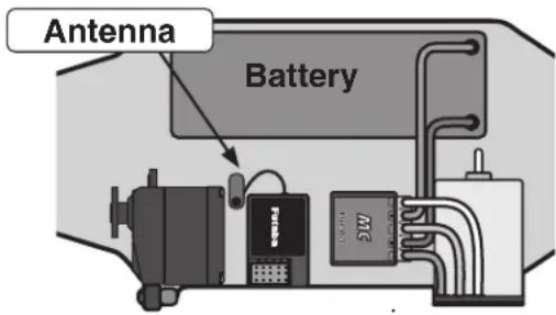
Install the receiver as far away as possible from the battery, motor controller, motor, silicon cord and other noise sources. Keep it away from the antenna wire, in particular.
Receiver vibration-proofing / waterproofing
(Car)
! Vibration-proof the receiver by wrapping it in foam rubber or other vibration-absorbing material and mount it with thick double-sided tape.
When using the receiver holder supplied with the model kit, mount the holder to the chassis through a rubber grommet.
(Boat)
Vibration-proof the receiver by wrapping it in foam rubber or other vibration-absorbing material. Also waterproof the receiver by sealing it in a plastic bag.
If the receiver is exposed to strong vibration and shock, it will operate erroneously due to the invasion of water drops and you may lose control of the model.

When using the receiver holder supplied with the kit, install the receiver through a rubber grommet.
Foam rubber, etc.

Wrap the receiver in foam rubber or other vibration-absorbing material. Do not use hard material. Hard material does not have a vibration-proofing effect.
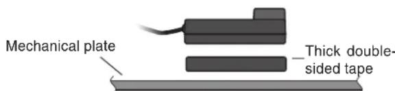
When mounting the receiver with double-sided tape, do not use a stiff tape. Stiff tape does not have a vibration-proofing effect.

Warning
Connector Connections
Be sure the receiver, servo, battery and connectors are fully and firmly connected.
If vibration from the model causes a connector to work loose while the model is in operation, you may lose control.
Servo Installation
When you install the servos, always use the rubber grommets provided in servo hardware bags. Mount the servos so they do not come in contact directly with the mount.
If the servo case comes in direct contact with the mount, vibration will be directly transmitted to the servo.
If this condition continues for a long time, the servo may be damaged and control will be lost.

Servo Throw
Operate each servo over its full stroke and be sure the linkage does not bind or is not loose.
The continuous application of unreasonable force to a servo may cause damage and excessive battery drain.
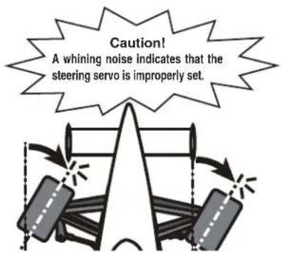
Decide the EPA value at the contact point.
Adjust the steering servo so that unreasonable force is not applied to the servo by the chassis at maximum servo travel.

Adjust the throttle servo so that unreasonable force is not applied when the engine carburetor is fully open, fully closed, and the brakes are applied fully.
If the brakes overheat while running, their ability to function properly decreases. Before running, adjust the suitable maximum servo travel so that unreasonable force is not applied even when the servo travel is increased while running.

Warning
Electronic Speed Control
Install the heat sinks where they will not come in contact with aluminum, carbon fiber or other parts that conduct electricity. If the ESC (Electronic speed control) heat sinks touch other materials that conduct electricity a short circuit could occur. This could result in loss of control and damage to the system.
Motor Noise Suppression
Always install capacitors to suppress noise when electric motors are used. If capacitors are not properly installed you could experience erratic operation and reduced range as well as loss of control.
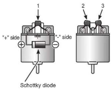
Motors with no suppressor capacitors, or inadequate suppression, may cause the receiver to malfunction. Always solder the capacitors supplied to your motor.
The Schottky diode improves the efficiency of the speed control / motor combination and provides extra protection to the brake FETs. The white ring must always face the positive side.
Other Noise Suppression Methods
! Be sure there are no metal parts in your model which under vibration can come in contact with other metal parts. Metal to metal contacts under vibration will emit a high frequency noise that will affect the receiver's performance. You could experience erratic operation and reduced range as well as loss of control.
Preparations (Transmitter)
Before setting the Transmitter functions, check and set these items next.
(Display when power switch turned on)
When the power switch is turned on, the currently selected model number is displayed. Check if this number is the model number you want to set-up. To change the model number, use the Model Select function (page 46).

Receiver Type Check (RX MODE)
This mode sets the RX type of the transmitter to match the receiver and servos used. The T4PV transmitter uses the telemetry type T-FHSS ("TFH") system.
It can also use the conventional S-FHSS ("SFH") system. Because the R304SB receiver supplied with the T4PV uses the telemetry type T-FHSS("TFH") system, its RX type must be set to the T-FHSS high speed mode ("TFH-HI") or the T-FHSS normal mod"TFH-NR"). Never use analog servos when the RX type was set to the T-FHSS ("TFH") 2.4GHz system high speed mode "TFH-HI" or the S-FHSS ("SFH") high speed mode "SFH-HI". The servos may be damaged. For example, if analog servos are used with a telemetry type T-FHSS receiver (R304SB, etc.), the RX type must be set"TFH-NR", and if analog servos are used with an S-FHSS receiver (R2104GF, R204FG-E, etc.), the RX type must be set to S-FHSS ("SFH-NR") system normal mode system. When using digital servos (including BLS Series brushless servos), any RX type can be used.
If the receiver used and the RX type settings are different, change the RX type using the "RX MODE" function. Which RX type is set can be checked at the HOME screen.
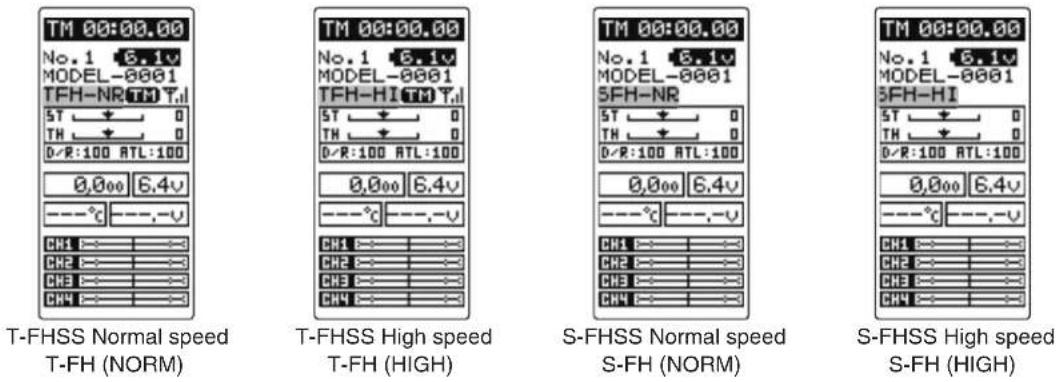
Receiver Type Change & How To Link
The first operation described below sets the RX type. Next, the transmitter and receiver are linked and the transmitter ID number is memorized at the receiver so that signals from other transmitters will not be received. The telemetry type T-
FHSS also simultaneously memorizes the ID n the receiver at the transmitter so that data from other receivers will not be received.
The RX type setting and transmitter and receiver linking methods are described here. Refer to the figure at the right for the edit buttons used.
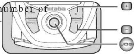
1 Call the MENU 1 screen from the HOME screen by moving the (JOG) button up, down, left or right. Select "RECEIVER" by moving the (JOG) button up or down, and display the "RX MODE" screen by pressing the (JOG) button.
2 Move the cursor to "TYPE: ----" by the (JOG) button up or down operation, and select the RX type with the (+) button or (-) button.
When the (JOG) button is pressed for approximately 1 second, an electronic sound is generated and setting ends.
![graph TD A["***MENU***"] --> B["JOG"] B --> C["JOG"] C --> D["RX MODE M01 T-FH NORM (NO LINK)"] C --> E["TYPE: T-FH (NORM)"] C --> F["TELEMETRY"] C --> G["LINK: EXEC"] H["RECEIVER"] --> I["JOG"] I --> J["Select "RX MODE" by (JOG) button."] K["EXP"] --> L["JOG"] M["SPEED"] --> N["JOG"] O["T…](/content/2026/07/1455774/images/236efdeace744bcd64135ecf1c4b05920ceb53dae67ea9454ec69c707bd9406f.jpg)
![graph TD A["Select TYPE with the (JOG) button."] --> B["Select RX type with the (+) or (-) button."] C["Press the (JOG) button for approximately 1 second."] --> D["Push"]](/content/2026/07/1455774/images/38f6ae215dc38c89ab04f8a51cd64d6484564633fbdde8b3545b205eac06ce54.jpg)
*When using an S-FHSS(SFH) system (R2104GF, R204GF-E, etc.) receiver, after reaching this point set the transmitter power switch to OFF and go to "Receivers other than T-FHSS" on page 36.
3 Bring the transmitter and receiver to within 50cm of each other (do not allow the antennae to touch) and turn on the receiver power.
4 Press the T4PV transmitter's (JOG) button up or down to move the cursor to "LINK: EXE". When the (JOG) button is pressed for approximately 1 second, "PUSH RX LINK SW" ap-
pears on the screen and a 20 second countdown begins. Countdown can be canceled at any time pressing the (JOG) button up/down or left/right.
![graph TD A["RX MODE\nM01\nT-FH NORM\n(NO LINK)"] --> B["TYPE: T-FH\n(NORM)"] B --> C["TELEMETRY"] C --> D["LINK: EXEC"] B --> E["R304SB"] E --> F["Futaba\nR304SB"] F --> G["LED SW"] F --> H["SW"] F --> I["LED 4"] F --> J["LED 3"] F --> K["LED 2"] F --> L["LED 1"] F --> M["LED 2.5/2.5"] F --> N["LED…](/content/2026/07/1455774/images/08b7865dfa798d7ba1829a035d9fb115f5a36f83910739fb07ac47cf9a48a1f5.jpg)
5 During the 20 second countdown, push up the receiver side tact switch for approximately 2 seconds. The LED will begin to
blink red. After the receiver LED switches from blinking red to green - red - green steady light, the T4PV generates an electronic beeping sound, and "LINK:OK" and "COMPLETE!" appear on the screen. Reading of the mutual IDs ends and the memorized receiver ID number appears on T4PV screen. If an error screen
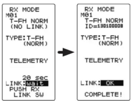
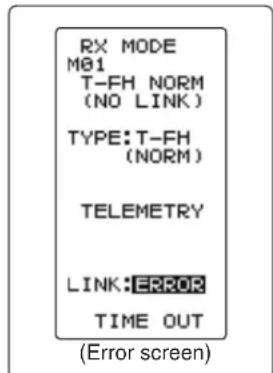
appears, linking failed. Retry linking. If the transmitter and receiver are linked normally, set the power switch to the OFF position and then return it to the PWR ON position. If the receiver LED lights green, linking was successful. Now check servo operation.
*The T4PV and a telemetry type T-FHSS receiver (R304SB, etc.) mutually memorize the combined ID linked last at each model memory.
Since the T4PV can memorize only 1 receiver ID at each model memory, multiple T-FHSS receivers cannot be used with the same model memory. When changing the receiver at the same model memory, re-link the previously linked receiver.
When using multiple telemetry type T-FHSS receivers, link and combine them with each T4PV model memory.
However, multiple receivers cannot be linked to multiple model memories.
The telemetry function communications status can be checked at the HOME screen.
The telemetry ON/OFF and communication status can be checked at the HOME screen.


Telemetry function :OFF- Telemetry function :
- Telemetry function :ON
- Receiver ID setting complete
- Data receiving sensitivity display
-
TH-OFF shows that data cannot be received because it is outside the data receiving range or because of the effects of an obstruction or the receiver power is OFF after receiver ID check.
-
Receiver ID before setting or ID mismatch.
- When the receiver ID is set, before ID check in the receiver power OFF stat.
Receivers Other Than T-FHSS
1 Bring the transmitter and the receiver close to each other, within 20 inches (half meter).
2 Turn on the transmitter.
3 Turn on the receiver.
4 Push the tactile switch of the receiver.
When the link is complete, the LED in the receiver changes to solid green.

Precaution:
If there are many Futaba 2.4GHz systems (T-FHSS/ S-FHSS) turned on in close proximity to your receiver might not link to your transmitter. In this case, even if the receiver's LED stays solid green, unfortunately the receiver might have established a link to one of other transmitters. This is very dangerous if you do not notice this situation. In order to avoid the problem, we strongly recommend you to double-check whether your receiver is really under control by your transmitter by giving the stick input and then checking the servo response.
*Please refer to the table below for LED status vs receiver's condition.
LED status vs receiver's condition:
| No signal reception Red : On | |
| Receiving signals Green: On | |
| Receiving signals, but ID is unmatched. Green: Blink | 1 (T-FHSS ,Red : On) |
| Unrecoverable failure (EEPROM,etc.) LED: Red and Green turn on | alternately |
*1: LED could be change to red during intermittently during data processing.
Warning
After the linking is done, please cycle receiver power and check if the receiver to be linked is really under the control of your transmitter.
Do not perform the linking procedure with motor's main wire connected or the engine operating as it may result in serious injury.
The throttle servo travel can be set to 5:5 or 7:3 for throttle trigger operation as required by the throttle mode function (page 88).

Trims Initial Set-Up
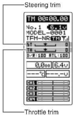
- Steering trim (DT1) check
On the initial set-up, steering trim is assigned to the DT1 trim lever upper right side of the steering wheel. Operate the DT1 and make sure the marker moves on the ST graph. If default has been changed, test steering trim in its new location. After checking the trim, set the trim display to the center (N) position.
- Throttle trim (DT2) check
On the initial set-up, throttle trim is assigned to the DT2 trim lever upper left side of the steering wheel. Operate the DT2 and make sure the marker moves on the TH graph. If the default has been changed, test the throttle trim in its new location. After checking the trim, set the trim display to the center (N) position.
Throttle trim (DT2) Steering trim (DT1)

- Steering dual rate (DT5) check
At initial set-up, steering dual rate (D/R) is assigned to the DT5 trim lever, at the grip of the transmitter. Operate the DT5 and check if the D/R value displayed on the screen changes. After checking D/R, set the steering dual rate to 100%.
- Throttle ATL (DT6) check
At initial set-up, throttle ATL (ATL) is assigned to the DT6 trim lever, below the DT5. Operate the DT6 and check if the ATL value displayed on the screen changes. After checking ATL, set throttle ATL to 100%.

(Set-Up Procedure When Installed In a Car)
When installing the servos in a car, performing function set-up in the following order is recommended.
1 Perform step 1 to Trims Initial Set-Up of Preparations on the preceding page.
2 Set the servo direction of operation using the Reverse function. (p.50)
- The servo installation method and linkage direction depend on the kit. Therefore, the servo operation direction may have to be reversed relative to transmitter operation. Before installing the servo, check the operating direction and set it using the Reverse function.
3 Set the subtrim and adjust the servo neutral point. (p.51)
4 Set the trigger travel by adjusting the throttle trigger mechanical ATL to your liking. (p.22)
- When the stroke was adjusted, compensate the throttle by adjuster function. (p.127)
5 Set EPA of each channel and adjust the servo throw (travel). (p.52)
Operation Of Screen
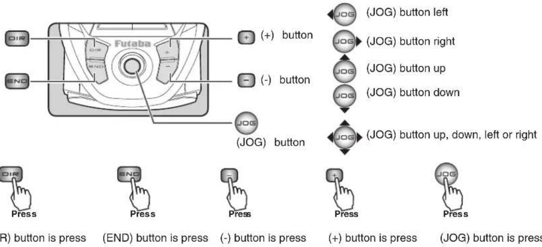
In this instruction manual, Edit Buttons are represented by the symbols shown below. The (JOG) button can be operated in 4 directions: up, down, left, and right.
Calling The Menu Screen
Refer to the map below for the method of displaying the function setting menu screen from the PWR HOME screen or DISP HOME screen and the method of returning from the menu screen to the PWR HOME screen or DISP HOME screen.
![graph TD A["DISP HOME screen"] --> B["JOG"] C["PWR HOME screen"] --> D["END"] B --> E["***MENU*** 1 2 3"] D --> F["***MENU*** 1 2 3"] E --> G["STR MIX"] F --> H["TELEMETRY"] G --> I["END"] H --> I I --> J["Press"] K["Press"] --> L["END"] style A fill:#f9f,stroke:#333 style C fill:#f9f,stroke:#333 st…](/content/2026/07/1455774/images/146b499b1ea1c132e313f426a94186b73e4180e951c9194bb6bd979cbfb24841.jpg)
Selecting Items On The Menu Screen
The item indicated by the reverse displayed cursor on the screen is selected.
The cursor is moved by (JOG) button in up or down movements. The cursor movement figure shown below is an example of the MENU 1 screen. However, movement of the cursor is the same in all of the screens.
For instance, if the (JOG) button is pressed when the cursor is at the end point (EPA) on the MENU 1 screen, the end point (END POINT) function setting screen appears.
![graph TD A["Move the cursor (JOG) button down operation"] --> B["->EXP"] B --> C["->SPEED"] C --> D["->TH A.B.S"] D --> E["->TH ACCEL"] E --> F["->END POINT"] F --> G["->SUBTRIM"] G --> H["->REVERSE"] H --> I["->D/R ATL"] I --> J["->FAIL SAFE"] J --> K["->MODEL"] K --> L["->RECEIVER"] L --> M["->JOG…](/content/2026/07/1455774/images/61f1e0b6902db7679ac514ebf7624918ee7304d6231d269d843cfee93fe757ce.jpg)
Value Of Each Function And Changing The Set Value
Values, settings, and other data on all the function setting screens are changed with the (+) and (-) buttons.
![REVERSE *STR *THR *CH3 *CH4 REV← →NOR Example: Select the channel to be changed at the REVERSE screen by (JOG) button up or down operation, and set the servo direction by selecting "NOR" or "REV" with the (+) button or (-) button. END POINT [RT] *STR LFT RGT 100 100 *THR FWD BRK 100 100 *CH3 UP DWN…](/content/2026/07/1455774/images/32fbd9f0dbc91fb9f8f60716e4c93b6a31c7804c3153854edecbbc87c23c3945.jpg)
Basic Menu Japanese Katakana Character Display
On the system menu, the basic menu screen shown below can be displayed in Japanese katakana characters.
![graph TD A["ENG"] --> B["1 2 3 EXP"] B --> C["TH A.B.S"] C --> D["TH ACCEL"] D --> E["END POINT"] E --> F["SUBTRIM"] F --> G["REVERSE"] G --> H["D/R ATL"] H --> I["FAIL SAFE"] I --> J["MODEL"] J --> K["RECEIVER"] L["カナ (katakna)"] --> M["1 2 3 EXP"] M --> N["STP-ト"] N --> O["TH A.B.S"] O --> P["アクセレ…](/content/2026/07/1455774/images/daac51fa1734e80022b1fa58f5949439d16b583cf3a1459a45d93de638f68f92.jpg)
Custom Menu
With the T4PV, setting items often used can be registered as up to 8 menus. A different custom menu can be created for each model memory. The custom menus can also be copied to other models by model copy function (page 47).
Displaying the custom menu screens
The custom menu screens can be displayed by pressing the (DIR) button from any screen.
![graph TD A["All screens, including the home screen"] --> B["DIR"] B --> C["CSTM MENU<br>*MENU<br>MODIFY: INH"] C --> D["EXP<br>SPEED<br>TH A.B.S<br>TH ACCEL<br>END POINT<br>SUBTRIM<br>REVERSE<br>D/R ATL"] D --> E["EXP<br>5TR: 0<br>FWD: 0<br>BRK: 0"] E --> F["EXP screen (Custom menu screen)"] F --> G…](/content/2026/07/1455774/images/fb01c2a5eebeb489a51b727eebd60544900dd82d5698bc2e6a842ca4aa0e7e32.jpg)
Menu assignment
1 Call the custom menu screen by pressing the (DIR) button.
2 Select the setting item "MODIFY" by moving the (JOG) button up or down. Use the (+) or (-) and set the function to the "ACT" state.
3 Move the cursor and select the location to be assigned a function by moving the (JOG) button up or down.
Select the function to be assigned by (+) or (-) button.
4 When assignment is complete, return to the HOME screen by pressing the (END) or (DIR) button.
Select the setting item "MODIFY" by moving the (JOG) button up or down. Use the (+) or (-) and set the function to the "ACT" state.

| Function List | ||
| Function Abbreviation | Description Of Function Page No | |
| EXP | Steering curve adjustment/ Throttle curve adjustment | P-57 |
| SPEED | Steering servo delay/ Throttle servo delay | P-60 |
| TH A.B.S | Pumping brake | P-65 |
| TH ACCEL | Reduces the "lag time" of the throttle from the neutral position. | P-63 |
| END POINT | End point adjustment | P-52 |
| SUBTRIM | Servo center position fine adjustment | P-51 |
| REVERSE | Servo operation reversing | P-50 |
| D/R ATL | Steering angle adjustment while running/ Brake side adjustment | P-69 |
| FAIL SAFE | Fail safe, battery fail safe | P-55 |
| MODEL | Model memory call/ Model memory copy/ Model memory reset | P-45 |
| RECEIVER | Receiver type selection/linking with telemetry type T-FHSS system receiver | P-33 |
| STR MIX | Uses 2 servos to individually control the left and right steering. | P-74 |
| BRAKE MIX | Front and rear independent brake control for 1/5 GP car, etc. | P-76 |
| GYRO MIX | The sensitivity of Futaba car rate gyros can be adjusted. | P-84 |
| PROG MIX | Programmable mixing between arbitrary channels | P-78 |
| DUAL ESC | Front and rear ESCs mixing | P-82 |
| 4WS MIX | 4WS mixing | P-80 |
| CPS MIX | The CPS-1 of Futaba LED controller can be adjusted. | P-86 |
| TH MODE | Throttle servo neutral position/ Idle-Up/ Neutral brake/ Engine cut | P-88 |
| CH3/CH4 | Channel 3&4 servos operation position set/check | P-92 |
| TRIM DIAL | Selection of the function to be performed by digital trim (DT1-DT6) dial (DL1) | P-70 |
| SWITCH | Selection of the function to be performed by push switch (PS1, PS2) | P-72 |
| TELEMETRY | Displays the status during operation of each sensor unit and records the status in a data log. | P-114 |
| TLM VOICE | The Speech function. (telemetry) | P-119 |
| LOG | Log Setting, Start/ Stop | P-120 |
| SX LINK | Futaba S.BUS/S.BUS2 servo parameter setup | P-93 |
| MC LINK | MC851C/602C/402CR/950CR/940CR/960CR Link software setting function | P-97 |
| MDL TRANS | Data copy from T4PV to another T4PV | P-105 |
| TIMER | Up, down, or lap timer | P-107 |
| LAP LIST | Lap timer data (lap time, total time) check | P-113 |
| ADJUSTR | Steering wheel and throttle trigger correction | P-127 |
| DIREC MDL | Direct Model memory call | P-44 |
| SYSTEM | LCD contrast/backlight/Battery type/buzzer/power off forgotten alarm/Basic menu character display /HOME screen display mode | P-123 |
| MDL SELE | Model memory call | P-46 |
| MDL NAME | Model memory name set/modify, user name set/modify | P-49 |
Direct Model Call
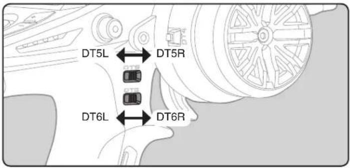
This function enables the registered model memory to be called when you turn on the power while operating DT5 or DT6, which are located on the T4PV grips. With this function, you can call the model memory which is different from the memory at the end of the previous operation without having to use the model selection function. DT5 and DT6 can be registered for right and left respectively for 4 models.
Press and hold digital trim(s) 5 or 6 while powering on the transmitter to select the optional models.
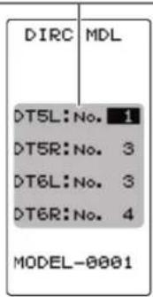
Display "DIRC MDL" screen using the following method:
![graph TD A["(HOME screen)"] --> B[" press "] B --> C["(MENU 1)"] C --> D[" JOG "] D --> E[" **MENU*** "] E --> F[" Select "DIRC MDL" "] F --> G[" JOG "] G --> H[" Press "] H --> I[" (CH3/CH4 screen)(MENU 3) "] I --> J[" DIRC MDL "] J --> K[" Print "] K --> L[" END "] L --> M[" (MENU 2) "]…](/content/2026/07/1455774/images/10a448b76644572937f02462e8de474a3181ebf78cb6b52f43c829d2cad37326.jpg)
Registration method of model memory
1 Select the setting item "DT5L", "DT5R", "DT6L", or "DT6R" by the (JOG) button up or down operation.
"DT5L": Push the DT5 trim lever to the left "DT5R": Push the DT5 trim lever to the right "DT6L": Push the DT6 rim lever to the left "DT6R": Push the DT6 trim lever to the right
2 Select the model memory number to be assigned by (+) or (-) button.
3 When finished with setting, return to the MENU screen by pressing the (END) button.
Select the setting item DT5L/DT5R, DT6L/DT6R"by the (JOG) button operation. Use the (+) or (-) and set the function to the appropriate model number you wish to have programmed to the switch.
Model "MODEL"
Forty model data (data for 40 R/C cars) can be saved in the T4PV transmitter. This menu selects the model and copies data between models.
Model Menu Display
The MENU 1 screen is displayed by moving the (JOG) button up, down, left or right at the HOME screen.
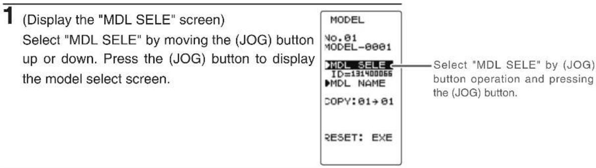
Select "MODEL" by moving the (JOG) button up or down on the MENU 1 screen and press the (JOG) button to display the MODEL screen.
When the (END) button is pressed from the MODEL screen, the display switches to the MENU 1 screen and can then be switched to the HOME screen by pressing the (END) button from the MENU 1 screen.
![graph TD A["(HOME screen)"] --> B[" press "] B --> C[" (MENU 2 ) "] C --> D[" (MENU 1 ) "] D --> E[" Select "MODEL" "] E --> F[" (MODEL screen) "] F --> G["Press "] G --> H[" (MODEL -0001 ) "] H --> I[" (MODEL SELECT ID=131400066) "] I --> J[" (MODEL NAME COPY:01→01)"] J --> K[" RESET: EXE…](/content/2026/07/1455774/images/478947d24cd9ecf40204b18ca58f109b179a0538fa063ba45924977b7ca4c19a.jpg)
Setting item
SELECT :Model selection
COPY :Model copy
RESET :Model reset

Forty model data (model data for 40 R/C cars) can be saved in the T4PV transmitter and used when the relevant model data is called.
Using the model select function
- Display the MODEL screen by referring to page 45.
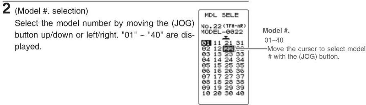
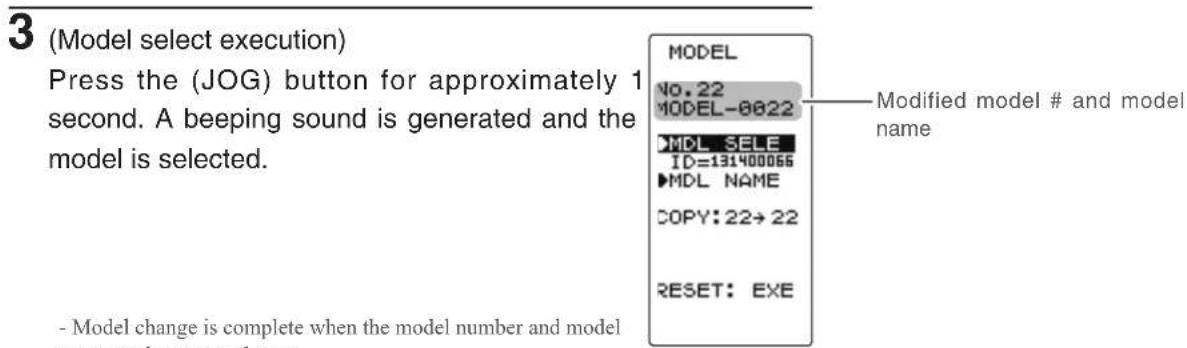
4 When finished with setting, return to the MENU screen by pressing the (END) button.
The contents of the currently selected model data can be copied to another model.
Using the model copy function
- Display the MODEL screen by referring to page 45.
1 (Selection of model copy)
Select "COPY" by moving the (JOG) button up or down.
MODEL
No.01
MODEL-0001
MDL SELE
ID=131400066
MDL NAME
COPY:01→91
RESET: EXE
Move the cursor to "COPY" with the (JOG) button.
2 (Model #. selection)
Select the copy destination model number with the (+) or (-) button. "01" \~ "40" are displayed.
MODEL
No.01
MODEL-0001
MDL SELE
ID=131400066
MDL NAME
COPY:01→82
MODEL-0002
RESET: EXE

Model #.
01\~40
- The copy destination model # with the (+) or (-) button.
3 (Model copy execution)
Press the (JOG) button for approximately 1 second. A beeping sound is generated and the model is selected.
MODEL
No.01
MODEL-0001
MDL SELE
ID=131400066
MDL NAME
COPY:01→52
MODEL-0002
RESET: EXE
COMPLETE!
Model name is also copied.
"COMPLETE!" is displayed.
-Copying is complete when "COMPLETE!" is displayed on the screen.
4 When finished with setting, return to the MENU screen by pressing the (END) button.
This function resets and initializes the contents of the currently selected model data.
However, the adjuster function (ADJUSTER), system setting (SYSTEM), and type of receiver mode (TYPE) are not initialized.
Using the model reset function
- Display the MODEL screen by referring to page 45.
1 (Selection of model reset)
Select "RESET" by moving the (JOG) button up or down.
MODEL
No.01
MODEL-0001
MDL SELE
ID=131400066
MDL NAME
COPY: 01→01
RESET: EXE
工
Move the cursor to "RESET" with the (JOG) button.
2 (Model reset execution)
Press the (JOG) button for approximately 1 second. A beeping sound is generated and the model is selected.
-Resetting is complete when the screen.
"COMPLETE!" is displayed on
MODEL
No.01
MODEL-0001
MDL SELE
ID=131400066
MDL NAME
COPY: 01→01
RESET: EXE
COMPLETE!
"COMPLETE!" is displayed.
3 When finished with setting, return to the MENU screen by pressing the (END) button.
The set RX type and T-FHSS receiver ID remain even if the model is reset. The same receiver can be used as is without re-linking.
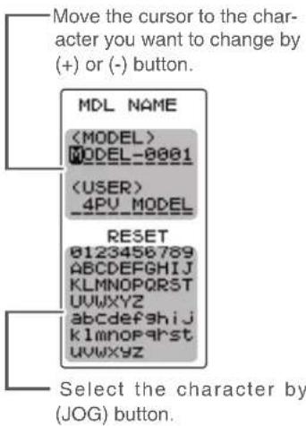
This function allows you to assign a ten character name to each model memory and use name.
Setting the model name and user name
- Display the MODEL screen by referring to page 45.
1 (Display the "MDL NAME" screen)
Select "MDL NAME" by moving the (JOG) button up or down. To display the model name screen, press the (JOG) button.
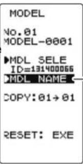
Move the cursor to "MDL NAME" with the (JOG) button.
![(MDL NAME screen) MDL NAME MODEL-0001 4PU_MODEL Model name User name RESET... 0123456789 ABCDEFGHIJKLMNOPQRSTUVWXYZ abcdefghijklmnopqrstuvwxyz abcdefghijklmnopqrstuvwxyz #&'()*,./ :<=?▲▼# 0■_ msh~ o ry[ ie· ] 0123456789 Character アイウエオカキケコ サシスセンタチツテト ナニヌネノヒフホ マミムメモヤヨ° ラソルレロ ワンラー アイクエオ カュヨッ](/content/2026/07/1455774/images/b0f9268ebcd826da872a333323fc72c2285da60d033d111b74329d35f70da34a.jpg)
When (JOG) button left or right operation is performed from both the left and right ends of the character list, the page (all 3 pages) is changed and the character set is selected.
(KATAKANA of the 3rd page is displayed when "KANA" is set by the "SYSTEM" function "MENU".)
2 (Move the cursor to the character you want to change.)
Select the model name character you want to set or change by moving the cursor by the (+) or (-) button. The selected character blinks.
3 (Selecting the character to be used)
Move the (JOG) button up, down, left or right to select the character you want to use from the list at the bottom of the screen. The selected character blinks. Now, press the (JOG) button. The character is entered and the model name or user name character. The cursor will automatically move to the right for the next characters.
Use the (JOG) button also to move the cursor to "RESET". Press the button approximately 1 second. You'll hear a beeping sound, which indicates that the model name has been initialized into the factory settings. A beeping sound is generated and the model name is initialized to the factory setting.
4 When finished with setting, return to the MODEL screen by pressing the (END) button.


Function
This function reverses the direction of operation of the servos related to transmitter steering, throttle, and channels 3/4 operation.
However, when the position set by trim or subtrim shifts from the center, the center becomes the opposite side.
Display to "REVERSE" screen using the following method:
![graph TD A["(HOME screen)"] --> B[" press "] B --> C["(MENU 2) [1"] 2] 3["Menu 1) [3"] 4["Press "] C --> D["END"] D --> E["(MENU 3) [5"] 6] 7["Menu 1"] 8["Press "] E --> F["END"] F --> G["(REVERSE screen) [REV NOR *STR *THR *CH3 *CH4 REV←→NOR"] G --> H["END"] H --> I["(REVERSE screen) [REV NOR *STR…](/content/2026/07/1455774/images/9d3d8b48341a80602b07a84c7fe327144f691dee7794cfe6ac29f8814c1429ab.jpg)
Servo reverse function setting
(Preparation)
- Select the channel to be set by moving the (JOG) button up or down.
Setting item
STR :Steering (1st channel)
THR : Throttle (2nd channel)
CH3 :3rd channel
CH4 :4th channel
1 (Servo reverse setting)
Use the (+) or (-) button to reverse the servo operation direction.
NOR/REV can also be set by moving the (JOG) button left or right.
(Each channel can be set similar.)

Move the cursor to "STR, THR, CH3 and CH4" with the (JOG) button.
2 When finished with setting, return to the MENU screen by pressing the (END) button.
Select button
- Select with the (+) or (-) buttons.
Or use the jog dial left or right to set the normal, reverse operations.
Use this function to adjust the neutral position of the steering, throttle, channel 3 and channel 4 servos.

Display to "SUBTRIM" screen using the following method:
![graph TD A["(HOME screen)"] --> B[" press "] B --> C["END"] C --> D["(MENU 2) MENU 1) MENU 3) MENU 1) MENU 1) (SUBTRIM screen) (SUBTRIM)<br> D --> E[ Select "SUBTRIM " "] E --> F["Press "] F --> G["END"] G --> H["Press "] H --> I["Subtrim"]](/content/2026/07/1455774/images/ca26311cc9fd5d2cf5707011cd1921493e3fd563bd0b31ab4276e066f48f23c6.jpg)
Steering and throttle center trim
When assigning DT1, DT2, or other digital trims to another function, make adjustments at this screen.
Subtrim adjustment
(Preparation)
- Set the steering and throttle digital trims to the neutral "0" position. Set CH3 and CH4 to the center "0" position.
Setting item
STR :Steering (1st channel)
THR : Throttle (2nd channel)
CH3 :3rd channel
CH4 :4th channel
1 (Subtrim adjustment)
Use the (+) or (-) button to adjust the center.
(Each channel can be set similar.)

Move the cursor to "STR, THR, CH3 and CH4" with the (JOG) button.
Adjustment buttons
- Use the (+) and (-) buttons to make adjustments.
- Return to the initial value by pressing the (+) and (-) buttons simultaneously (approx. 1 sec).
Subtrim Values
STR :L100\~R100
THR :B100\~F100
CH3 :-100\~+100
CH4 :-100\~+100
Initial value : 0
Trim Values
STR :L100\~R100
THR :B100\~F100
Initial value : 0
2 When finished with setting, return to the MENU screen by pressing the (END) button.
End Point Adjuster "END POINT"
(All channel)
Use this when performing left and right end point adjustments, throttle high side/brake side operation amount adjustment, or channel 3 and channel 4 servo up side/down side operation amount adjustment during linkage.
- Correct the maximum steering angle for left and right steering angles when there is a difference in the turning radius due to the characteristics of the vehicle.
Maximum steering angle
The EPA function basically determines the maximum steering angle of each channel.
The functions shown below may have been adjusted or the operating range set by EPA function may be exceeded. Check the linkage each time the following functions are adjusted.
- Sub trim (all channels) ...... P51
- Program mixing slave side (all channels) .....P78
- Idle up (throttle) P89
- Throttle off, Engine Cut (throttle) ...... P91
- Throttle acceleration (throttle) ...... P63
ATL trim
ATL trim allows adjustment of the brake side operation amount during operation.
Therefore, when the operating angle is adjusted with throttle EPA, ATL trim must also be taken into account.

Warning
Operate each servo over its full stroke and be sure the linkage does not bind or is not loose.
The continuous application of unreasonable force to a servo may cause damage and excessive battery drain.

Decide the EPA value at the contact point.

Adjust the steering servo so that unreasonable force is not applied to the servo by the chassis at maximum servo travel.
Adjust the throttle servo so that unreasonable force is not applied when the engine carburetor is fully open, fully closed, and the brakes are applied fully.
If the brakes overheat while running, their ability to function properly decreases. Before running, adjust the suitable maximum servo travel so that unreasonable force is not applied even when the servo travel is increased while running.
Display to "END POINT" screen using the following method:
![graph TD A["(HOME screen)"] --> B["END"] B --> C["Press"] C --> D["(MENU 2)"] D --> E["1 2 3"] E --> F["***MENU***"] F --> G["END POINT"] G --> H["END POINT (MENU 1)"] H --> I["*STR LFT RGT 100 *THR FWD BRK 100 100 *CH3 UP DWN 100 100 *CH4 UP DWN 100 100"] H --> J["END"] J --> K["Press"] K --> L["EN…](/content/2026/07/1455774/images/cc3dcf2795bd22e8c74ba2856bb27996e2fbed9158fa6bb6575b1fc9aab671b7.jpg)
Setting item selection
(Steering and Throttle direction)
- The direction (STR LFT and STR RGT) linked with the steering wheel is switched.
- The direction (THR FWD and THR BRK) linked with the throttle trigger is switched.
Setting item (channel and direction)
STR LFT :Steering (left side)
STR RGT :Steering (right side)
THR FWD : Throttle (foward side)
THR BRK : Throttle (brake side)
CH3/CH4 UP :3rd or 4th channel (up side)
CH3/CH4 DWN :3rd or 4th channel (down side)
Steering (END POINT) adjustment
(Preparation)
- Before setup of the steering end point adjustment (END POINT), set the steering D/R trim (initial setup: DT5) to the maximum steering angle position 100%.
- Use the (JOG) button to select the setting item "RGT" and make the following adjustments: and make the following adjustments: Or turn the steering wheel to select LFT or RGT.
1 Steering (left side) adjustment Turn the steering wheel fully to the left and use the (+) or (-) buttons to adjust the steering angle.
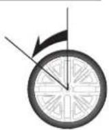
2 Steering (right side) adjustment Turn the steering wheel fully to the right and use the (+) or (-) buttons to adjust the steering angle.
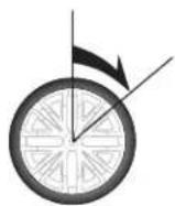
3 When finished with setting, return to the MENU screen by pressing the (END) button.

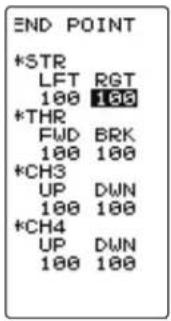
Adjustment buttons
- Use the (+) and (-) buttons to make adjustments.
- Return to the initial value by pressing the (+) and (-) buttons simultaneously (approx. 1 sec).
Steering EPA
STR LFT :0\~120 STR RGT :0\~120 Initial value :100
Throttle (END POINT) adjustment
(Preparation)
- Before setting the throttle end point adjustment (END POINT), set the throttle ATL trim (initial setup: DT6) to the maximum throttle angle position 100%.
- Select the setting item "FWD" by moving up or down on the (JOG) button and make the following adjustments: Or move the throttle trigger fore or aft to select FWD or REV.
1 Throttle (forward side) adjustment
Pull the throttle trigger fully to the high side and use the (+) or (-) buttons to adjust the throttle angle. However, when using an electronic motor speed controller (ESC), set to 100%.
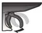
2 Throttle (brake side/reverse side) adjustment
Move the throttle trigger fully to the brake side and use the (+) or (-) buttons to adjust the throttle angle. However, when using an electronic motor speed controller (ESC), set to 100%.
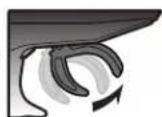
3 When finished with setting, return to the MENU screen by pressing the (END) button.
3rd & 4th channel servo (END POINT) adjustment
1 3rd/4th channel servo (up side) adjustment
Select the setting item "CH3 or CH4 UP" by moving the (JOG) button up or down. Set the 3rd or 4th channel dial fully to the up side (+ side) and use the (+) or (-) buttons to adjust the servo angle.
2 3rd/4th channel servo (down side) adjustment
Select the setting item "CH3 or CH4 DWN" by moving the (JOG) button up or down. Set the 3rd or 4th channel dial fully to the up side (- side) and use the (+) or (-) buttons to adjust the servo angle.
3 When finished with setting, return to the MENU screen by pressing the (END) button.
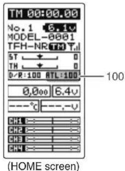

Adjustment buttons
- Use the (+) and (-) buttons to
make adjustments. - Return to the initial value by pressing the (+) and (-) buttons simultaneously (approx. 1 sec).
Throttle EPA
THR FWD :0\~120
THR BRK :0\~120
Initial value :100

Adjustment buttons
- Use the (+) and (-) buttons to
make adjustments. - Return to the initial value by pressing the (+) and (-) buttons simultaneously (approx. 1 sec).
3rd & 4th channel EPA
CH3/CH4 UP :0\~120
CH3/CH4 DWN :0\~120
Initial value :100
Fail Safe Mode (F/S)
This function moves each servo to a preset position when the receiver cannot receive signals from the transmitter for some reason.
-The fail safe data is transferred from the transmitter to the receiver 10 seconds after the transmitter power was turned on. The data is transferred every 5 seconds after that. Be careful because normally the transmitter power is turned on first and the receiver power is turned on next and the data is transferred for approximately 10 seconds after the receiver power is turned on. -For GP cars, for safety we recommend that this fail safe function be used to set the throttle channel in the direction in which the brakes are applied.
Hold mode (HOLD)
This function holds the receiver in its position immediately before reception was lost. It is the T-FHSS type (R304SB...etc) and the S-FHSS type (R2104GF...etc) receiver only function.
Off mode (OFF)
This function stops output of signals to the servos and places the servos into the free state when the receiver cannot receive.
The F/S, HOLD, and OFF modes are automatically reset when signals from the transmitter can be received again.
Battery fail safe function (B-FS)
If the receiver battery voltage drops below a certain value when this function is enabled, the throttle servo moves to the position set by fail safe function. When the battery voltage recovers, the battery fail safe function is automatically reset.
-This function cannot be used when the throttle (TH) is not set to fail safe (F/S).
Display to "FAIL SA FE" screen using the following method:
![graph TD A["(HOME screen)"] --> B[" press "] B --> C["(MENU 2)"] C --> D[" Select "FAIL SAFE" "] D --> E[" (FAIL SAFE screen)(MENU 1 ) "] E --> F[" press "] F --> G[" (FAIL SAFE) "] G --> H[" (FAIL SAFE) "] H --> I[" (FAIL SAFE) "] style A fill:#f9f,stroke:#333 style C fill:#ccf,stroke:#33…](/content/2026/07/1455774/images/2be8bacc9e053c1656d123015610be96507d36058ed06c01e75253a1608a505b.jpg)
Fail safe mode selection
(Preparation)
- Select the channels "MODE" to be set by moving the (JOG) button up, down, left or right.
1 (Mode selection)
Select the mode by (+) or (-) button.
(Each channel can be individually set.)
2 When finished with setting, return to the MENU screen by pressing the (END) button.
When setting fail safe, set the servo position by the following method.
Fail safe function setup
1 (Servo position setup)
When the fail safe function operates, select the setting item "POSI" by moving the (JOG) button up or down. The steering wheel, the throttle trigger or 3rd, 4th channel dial remains in the desired operation position. When the (JOG) button is pressed for approximately 1 second, the servo position is displayed and you can confirm that the function was set.
(Each channel can be set similar.)
2 When finished with setting, return to the MENU screen by pressing the (END) button.
Battery fail safe function ON/OFF
(Preparation)
- Select the setting item by moving the (JOG) button up or down. For Battery F/S function select "OFF" or "ACT" of "B-FS".
For voltage setting, select VOLT. (This applies to the T-FHSS system only.)
The S-FHSS system is fixed at 3.8v.
1 (Battery fail safe function ACT/OFF)
The battery fail safe function ACT/OFF and voltage setting which activates the B-FS function can be switched by (+) or (-) button.
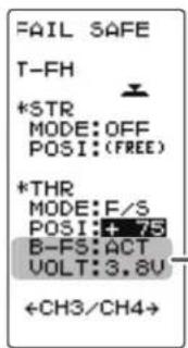
2 When finished with setting, return to the MENU screen by pressing the (END) button.
FAIL SAFE screen
![graph LR A["FAIL SAFE"] --> B["T-FH TRANS"] B --> C["*STR MODE:OFF POSI:(FREE)"] A --> D["*THR MODE:OFF POSI:(FREE)"] A --> E["B-FS:---- VOLT:----"] A --> F["←CH3/CH4→"] G["FAIL SAFE"] --> H["T-FH TRANS"] H --> I["*CH3 MODE:OFF POSI:(FREE)"] G --> J["*CH4 MODE:OFF POSI:(FREE)"] G --> K["←STR/THR→"]…](/content/2026/07/1455774/images/2b32558d06e765ec10c869723b6b2dd424253614e36928bc441f8b5fbb2653a8.jpg)
F/S mode
OFF, HOLD, F/S
F/S mode selection
- Select with the (+) or (-) buttons.
F/S position setup button
- The (JOG) button is pressed for approximately 1 second.

Battery fail safe function
OFF, ACT
Initial value: OFF
Select button
- Select with the (+) or (-) buttons.
B-F/S Voltage
3.8, 4.0, 4.2, 4.4, 4.6, 4.8, 5.0, 5.3, 5.6, 5.9, 6.2, 6.5, 6.8, 7.1, 7.4(V)
Initial value 3.8v
Select button
- Select with the (+) or (-) buttons.
Example:
Ni-MH /Ni-Cd 4cell---3.8V
Ni-MH /Ni-Cd 6cell---4.4V
LiFe 2cell---4.8V
Li-Po 2cell---5.6V
Exponential Adjustment "EXP"
(Steering/ Throttle system)
This function is used to change the sensitivity of the servo around the neutral position.
Display to "EXP" screen using the following method:
![graph TD A["(HOME screen)"] --> B[" press "] B --> C[" (MENU 2 ) "] C --> D[" **MENU*** "] D --> E[" Select "EXP" "] E --> F[" (EXP screen)(MENU 1 ) "] F --> G[" EXP "] G --> H[" Press "] H --> I[" (EXP screen)(MENU 1 ) "] I --> J[" (EXP screen) "] style A fill:#f9f,stroke:#333 style B fil…](/content/2026/07/1455774/images/f3102a8264b9ac24b33744d7373a7923e0c129869f72255a9412f15438e07836.jpg)
Setting item
STR :Steering
FWD : Throttle forward side
BRK : Throttle brake/ reverse side
STR (Steering EXP)
This function is used to change the sensitivity of the steering servo and around the neutral position. It has no effect on the maximum servo travel.
Racers Tip
When the setting is not determined, or the characteristics of the model are unknown, start with 0%. (When EXP is set to 0%, servo movement is linear.)

Steering EXP adjustment
(Preparation)
- On the EXP screen, select the setting item "STR" by moving the (JOG) button up or down.
1 When you want to quicker steering operation, use the (+) button to adjust the + side. When you want to make steering operation milder, use the (-) button to adjust the - side.

Adjustment range -100\~0\~+100
Adjustment buttons
- Use the (+) and (-) buttons to make adjustments.
- Return to the initial value by pressing the (+) and (-) buttons simultaneously (approx. 1 sec).
Vertical cursor moves in step with steering wheel operation.
2 When finished with setting, return to the MENU screen by pressing the (END) button.
FWD (Throttle Forward Side EXP)/ BRK (Throttle Brake Side EXP)
This function makes the throttle forward side and brake side direction servo operation quicker or milder. It has no effect on the servo maximum operation amount.
Advice
When the course conditions are good and the surface has good grip, set each curve to the + side (quick side). When the road surface is slippery and the drive wheels do not grip it, set each curve to the - minus (mild) side.
Throttle forward side EXP adjustment
(Preparation)
- On the EXP screen make the following adjustments:
1 Select the setting item "FWD" by moving the (JOG) button up or down. Use the (+) button to adjust for a faster throttle response or use the (-) button for a slower or milder throttle response.
Adjustment range
- 100 0 +100 %
Adjustment buttons
- Use the (+) and (-) buttons to make adjustments.
- Return to the initial value by pressing the (+) and (-) buttons simultaneously (approx. 1 sec).


2 When finished with setting, return to the MENU screen by pressing the (END) button.
Throttle brake side EXP adjustment
(Preparation)
- On the EXP screen make the following adjustments:
1 Select the setting item "BRK" by moving the (JOG) button up or down. Use the (+) button to adjust for a faster brake response or use the (-) button for a slower or milder brake response.
Adjustment range -100 \~ 0 \~ +100%
Adjustment buttons
- Use the (+) and (-) buttons to make adjustments.
- Return to the initial value by pressing the (+) and (-) buttons simultaneously (approx. 1 sec).
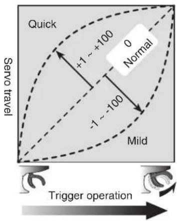

Vertical cursor moves in step with throttle trigger operation.
2 When finished with setting, return to the MENU screen by pressing the (END) button.
Dial / Trim Setting
The steering and throttle EXP adjustment (RATE) can be controlled with digital dial or digital trim. With the function select trim dial function (See page 70).
Servo Speed "SPEED"
(Steering system)
This function limits the maximum speed of the steering servo (Delay function).
Display to "SPEED" screen using the following method:
![graph TD A["(HOME screen)"] --> B[" press "] B --> C["END"] C --> D["Menu 2"] D --> E["1 2 3 EXP SPEED TH A.B.S END POINT SUBTRIM REVERSE D/R ATL FAIL SAFE MODEL RECEIVER"] E --> F["Select "SPEED""] F --> G["Press "] G --> H["(SPEED screen)(MENU 1)"] H --> I["SPEED *STR TURN:100 RETN:100 *…](/content/2026/07/1455774/images/c5f88e717fbb3d21fd7e86da7cc905d7d5b0a9faede8593c0e955bea155583ac.jpg)
Setting item
STR TURN :Steering turn side
STR RETN : Steering return side
THR TURN : Throttle turn side
STR (Steering Speed)
Quick steering operation will cause momentary understeering, loss of speed, or spinning. This function is effective in such cases.
![graph TD A["Understeering"] --> B["Spin"] B --> C["Smooth cornering"] style A fill:#f9f,stroke:#333 style B fill:#ccf,stroke:#333 style C fill:#cfc,stroke:#333](/content/2026/07/1455774/images/3cfe1aaf8a90924fefdd1ab6aac7d8a92ef29aa670d34113d31d3330097aaa61.jpg)
Without "SPEED" With "SPEED"
Operation
- The steering speed when the steering wheel is operated (TURN direction) and returned (RETN direction) can be independently set.
- If the steering wheel is turned slower than the set speed, the steering servo is not affected.
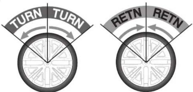
Steering Speed adjustment
(Preparation)
- On the SPEED screen make the following adjustments:
1 "TURN" direction adjustment
On the SPEED screen, select the setting item STR "TURN" by moving the (JOG) button up or down. Use the (+) or (-) buttons to adjust the delay amount.

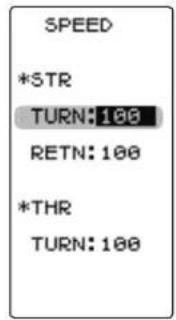
Adjustment range
1\~100% (each direction) At 100%, there is no delay.
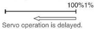
Adjustment buttons
- Use the (+) and (-) buttons to make adjustments.
- Return to the initial value by pressing the (+) and (-) buttons simultaneously (approx. 1 sec).
2 "RETN" direction adjustment
Select the setting item STR "RETN" by moving the (JOG) button up or down. Use the (+) or (-) buttons to adjust the delay amount.
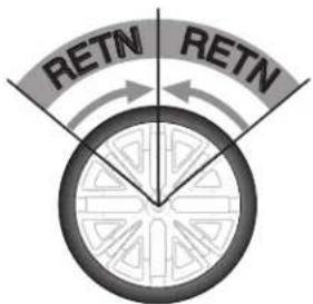

Adjustment range
1\~100% (each direction) At 100%, there is no delay.
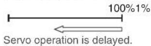
Adjustment buttons
- Use the (+) and (-) buttons to make adjustments.
- Return to the initial value by pressing the (+) and (-) buttons simultaneously (approx. 1 sec).
3 When finished with setting, return to the MENU screen by pressing the (END) button.
Setting example (Steering servo: BLS451 / BLS351) ... (Setting criteria)
- On road TURN side: Approx. 50\~80% RETURN side: Approx. 60\~100%
- Off road TURN side: Approx. 70\~100% RETURN side: Approx. 80\~100%
Dial / Trim Setting
The steering speed adjustment "TURN" and "RETN" can be controlled with digital dial or digital trim. With the function select trim dial function (See page 70).
THR (Throttle Speed)
Sudden throttle trigger operation on a slippery road causes the wheels to spin and the vehicle cannot accelerate smoothly. Setting the throttle speed function reduces wasteful battery consumption while at the same time permitting smooth, enjoyable operation.


Operation
-Throttle servo (ESC) operation is delayed so that the drive wheels will not spin even if the throttle trigger is operated more than necessary.
This delay function is not performed when the throttle trigger is returned and at brake operation.
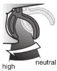
Throttle Speed adjustment
(Preparation)
- On the SPEED screen make the following adjustments:
1 (Delay adjustment)
On the SPEED screen, select the setting item THR "TURN" by moving the (JOG) button up or down. Use the (+) or (-) buttons to adjust the delay amount.

Adjustment range
1\~100%
At 100%, there is no delay.

Adjustment buttons
- Use the (+) and (-) buttons to make adjustments.
- Return to the initial value by pressing the (+) and (-) buttons simultaneously (approx. 1 sec).
2 When finished with setting, return to the MENU screen by pressing the (END) button.
Dial / Trim Setting
The throttle speed adjustment can be controlled with digital dial or digital trim. With the function selecttrim dial function (See page 70).
Throttle Acceleration "TH ACCEL"
(Throttle system)
The servo will jump to the input position at its maximum possible speed. Unlike exponential, which adjusts the whole throttle movement into a curve, throttle acceleration simply "jumps" away from neutral and then leaves the remaining response linear.
Operation
- Operation near the throttle trigger neutral position becomes a sharp rise.
- The forward and brake sides can be set separately.

Set value
The standard value (100% point) of this setup affects the operation amount set by throttle EPA function.
Convenient usage method
For nitro powered cars, the linkage must have a clearance because one servo controls the engine carburetor and brake. Thus, there is a noticeable time delay at both the forward and brake sides. Sharp response comparable to that of electric motor cars is obtained by reducing this clean the transmitter side.
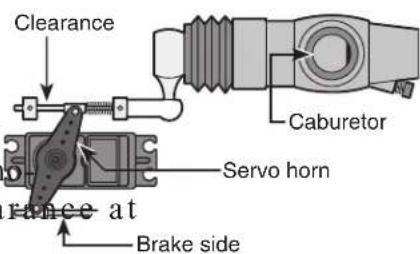
Display to "TH ACCEL" screen using the following method:
![graph TD A["(HOME screen)"] --> B[" press "] B --> C[" ENTER"] C --> D[" (MENU 2 ) "] D --> E[" (MENU 1 ) "] E --> F[" Select "TH ACCEL" "] F --> G[" (TH ACCEL screen) "] G --> H[" TH ACCEL "] H --> I[" *FWD "] H --> J[" RATE: 0 "] H --> K[" *BRK "] H --> L[" RATE: 0 "] style A fill:#f9f,s…](/content/2026/07/1455774/images/92329270a4d1425d8aad5ce706b0130e895c2d3624dd7a9be502666d9f0270f6.jpg)
Setup item
FWR RATE :Forward side acceleration
BRA RATE :Brake side acceleration
Throttle acceleration adjustment
(Preparation)
- On the TH ACCEL screen make the following adjustments:
1
(Forward acceleration amount adjustment) Select the setting item FWD "RATE" by moving the (JOG) button up or down. Use the (+) and (-) buttons to adjust the acceleration amount.

"0": No acceleration.
"100": Maximum acceleration (Approximately 1/2 of the forward side throttle angle).
2
(Brake side acceleration amount adjustment) Select the setting item BRK "RATE" by moving the (JOG) button up or down. Use the (+) and (-) buttons to adjust the acceleration amount.

"()": No acceleration.
"100": Maximum acceleration (Brake side maximum throttle angle).
Forward acceleration amount (FWD)
0\~100
Initial value: 0
Adjustment buttons
- Use the (+) and (-) buttons to make adjustments.
- Return to the initial value by pressing the (+) and (-) buttons simultaneously (approx. 1 sec).
Brake side acceleration amount (BRK)
0\~100
Initial value: 0
Adjustment buttons
- Use the (+) and (-) buttons to make adjustments.
- Return to the initial value by pressing the (+) and (-) buttons simultaneously (approx. 1 sec).
3
When finished with setting, return to the MENU screen by pressing the (END) button.
Dial / Trim Setting
The throttle acceleration adjustment amount (FWD), (BRK) can be controlled with digital dial or digital trim. With the function select trim dial function (See page 70).
A.B.S. Function "TH A.B.S"
(Throttle system)
When the brakes are applied while cornering with a 4 Wheel Drive or other type of vehicle, understeer may occur. Understeer can be eliminated and corners can be smoothly cleared by using this function.

Operation
- When the brakes are applied, the throttle servo will pulse intermittently. This will have the same effect as pump brakes in a full size car.
- The brake return amount, delay amount, pulse cycle, and brake duty can be adjusted.
ng the
Operation display
During ABS operation, the LED blinks.

Display "TH A.B.S" screen using the following method:
![graph TD subgraph (HOME screen) A["TH 02:00.80"] --> B["JOG"] B --> C["MENU 2"] C --> D["1 2 3"] D --> E["***MENU***"] E --> F["EXP SPEED TH A.B.S"] F --> G["END POINT END POINT"] G --> H["SUBTRIM REVERSE"] H --> I["D/R ATL FAIL SAFE"] I --> J["MODEL RECEIVER"] J --> K["Select "TH A.B.S""]…](/content/2026/07/1455774/images/fcc46a8c73ab13897824aa9bb6f13999b180af7c88352d8d5bdac7f92005f7f1.jpg)
Setup items
MODE : Function ON/Off
AB.P : Brake return amount
DELY : Delay amount
CYCL : Cycle speed
DUTY : Cycle duty ratio
- AB.P : Amount of brake return
Sets the rate at which the servo returns versus trigger operation for brake release. When set to 0%, the ABS function is not performed. When set to 50%, the servo returns 50% (1/2) of the trigger operation amount and when set to 100%, the servo returns to the neutral position.
ABS
![graph TD A["Servo travel"] --> B["TG.P (Trigger point)"] B --> C["DUTY (duty): X and Y ratio"] C --> D["X: (Brake application time)"] D --> E["Y: (Brake return time)"] E --> F["AB.P (Amount of brake return)"] F --> G["CYCL (Cycle)"] G --> H["Trigger operation"]](/content/2026/07/1455774/images/bbe7273f4fd1e7a41af0be395ca34c983da5d56196ea6e6e6ed98031dade30cc.jpg)
A.B.S. Function "TH A.B.S"
- DELY : Delay
Sets the delay from brake operation to ABS operation. When set to 0%, the ABS function is activated without any delay. At 50%, the ABS function is activated after a delay of approximately 1 second and at 100%, the ABS function is activated after a delay of approximately 2 seconds.
- CYCL : Cycle speed
Sets the pulse speed (cycle). The smaller the set value, the faster the pulse cycle.
Sets the trigger point at which the ABS function begins to operate at brake operation.
- DUTY : Cycle duty ratio
Sets the proportion of the time the brakes are applied and the time the brakes are released by pulse operation. The ratio can be set to HIGH, MID or LOW.
- MODE : Function ON/OFF
ABS function ON/OFF setting. When using the ABS function, set to "ACT (ON)".
A.B.S function adjustment
1 (Function ON/OFF)
Select the setting item "MODE" by moving the (JOG) button up or down. Set the function to the active state by pressing the (+) or (-) button.
"INH(OFF)": Function OFF.
"ACT(ON)": Function ON.
"ACT(OFF)": Switch OFF when setting switches.
2 (Brake return amount adjustment)
Select the setting item "AB.P" by moving the (JOG) button up or down. Use the (+) or (-) button to adjust the return amount.

"0": No return.
"50": Return to the 50% position of the brake operation amount.
"100": Return to the neutral position.
3 (Delay amount setup)
Select the setting item "DELY" by moving the (JOG) button up or down. Use the (+) or (-) button to adjust the delay amount.
"0": A.B.S. function performed without any delay.
"50": A.B.S function performed after an approximate 1 sec delay.
"100": A.B.S. function performed after an approximate 2 secs delay.
Select button
- Select with the (+) or (-) buttons.
Function ON/OFF (MODE)
INH (OFF), ACT (ON, OFF)
Brake return amount (AB.P)
0 \~ 50 \~ 100
Initial value: 50
- Brake return amount (AB.P) is influenced by the "EXP" rate on the brake side.
Adjustment buttons
- Use the (+) and (-) buttons to make adjustments.
- Return to the initial value by pressing the (+) and (-) buttons simultaneously (approx. 1 sec).
Delay amount (DELY)
0 \~ 100
Initial value: 0
Adjustment buttons
- Use the (+) and (-) buttons to make adjustments.
- Return to the initial value by pressing the (+) and (-) buttons simultaneously (approx. 1 sec).
4 (Cycle speed adjustment)
Select setting item "CYCL" by moving the (JOG) button up or down. Use the (+) or (-) button to adjust the pulse speed (cycle).
- The smaller the set value, the faster the pulse speed.

Cycle speed (CYCL)
1 \~ 30
Initial value: 10
Adjustment buttons
- Use the (+) and (-) buttons to make adjustments.
- Return to the initial value by pressing the (+) and (-) buttons simultaneously (approx. 1 sec).
5 (Trigger point setup)
Select setting item "TG.P" by moving the (JOG) button up or down. Use the (+) or (-) button to adjust the operation point.
- Sets the throttle trigger position at which the A.B.S. function is performed. The number is the % display with the full brake position made 100.
6 (Cycle duty ratio setup)
Select setting item "DUTY" by moving the (JOG) button up or down. Use the (+) or (-) button to select the duty ratio.

Trigger point (TG.P)
10 \~ 100
Initial value: 30
Adjustment buttons
- Use the (+) and (-) buttons to make adjustments.
- Return to the initial value by pressing the (+) and (-) buttons simultaneously (approx. 1 sec).
"LOW": Brake application time becomes shortest. (Brakes lock with difficulty).
"HIGH": Brake application time becomes longest (Brakes lock easily).
(Remark) For low grip, set at the LOW side and for high grip, set at the HIGH side.
7 When finished with setting, return to the MENU screen by pressing the (END) button.
Dial / Trim Setting
The brake return amount (AB.P), delay amount (DELY) and cycle (CYCL) can be controlled with digital dial or digital trim, with the function trim dial (See page 70).
Switch setting
Use PS1 or PS2 to switch the A.B.S. function ON/OFF.
See the function select switch function (See page 72).
A.B.S. Function "TH A.B.S"
Duty ratio (DUTY)
LOW - MID - HIGH
Initial value: MID
Adjustment buttons
- Use the (+) and (-) buttons to make adjustments.
- Return to the initial value by pressing the (+) and (-) buttons simultaneously (approx. 1 sec).
Fail Safe Unit
When the T4PV is used with the Futaba fail safe unit (FSU), it will scribed below. However, FSU cannot be used in the high speed mode.
operate as de
- When the FSU is connected to the throttle channel, and the A.B.S. function has been activated, the FSU LED will flash each time the servo operates. The reason for this is that the FSU responds to sudden data changes caused by A.B.S. function pumping operation. It does not mean that the fail safe function is activated. The servo will not be affected.
Example of A.B.S. function setting when S9352HV used
(There will be a slight difference depending on the state of the linkage.)
- Basic setting
AB.P: Approx. 30% (If this value is too high, the braking distance will increase.)
CYCL: 5\~7
DUTY: (When grip is low: LOW side, when grip is high: HIGH side)
DELY: 10\~15%
TG.P: Approx. 70% - When the wheels lock, or the car spins, when the brakes are applied fully
AB.P: Increase from 30%
DUTY: Shift to "LOW" side
DELY: Reduce the delay - When the braking effect is poor and the braking distance is long when the brakes are applied fully
AB.P: Decrease from 30%
DUTY: Shift to "HIGH" side
DELY: Increase the delay
1/5 scale car and other independent brakes and ABS
ABS can be independently set for the brakes which are controlled by the 3rd CH and 4th CH by using the brake mixing (BRAKE MIX) function described on page 74. For more information, read the brake mixing (BRAKE MIX) item.
Steering Dual Rate/ Throttle ATL "D/R ATL"
D/R (Steering dual rate)
The steering left and right servo travels are adjusted simultaneously. This setting is linked to transmitter grip trim lever DT5. When DT5 is assigned another function, dual rate can be adjusted with this screen.
ATL (Throttle ATL)
This function decreases the set value when the braking effect is strong and increases the set value when the braking effect is weak. This function is linked to transmitter grip trim lever DT6. When DT6 is assigned another function, this function can be set with this screen.
Display "D/R ATL" screen using the following method:
![graph TD A["(HOME screen)"] --> B[" press "] B --> C[" (MENU 2 ) "] C --> D[" (MENU 1 ) "] D --> E[" Select "D/R" ATL "] E --> F[" (D/R ATL screen) "] F --> G[" Press "] G --> H[" (D/R ATL screen) "] style A fill:#f9f,stroke:#333 style F fill:#ccf,stroke:#333](/content/2026/07/1455774/images/32d7d2a7d264f0cc1d36969603f4a2f0815ff12e2384a529098516acbb686fa1.jpg)
Dual rate adjustment
1 (Dual rate adjustment)
Select the setting item ST-D/R "RATE" by moving the (JOG) button up or down. Adjust the servo travel with the (+) and (-) buttons.
2 When finished with setting, return to the MENU screen by pressing the (END) button.
ATL function adjustment
1 (Brake amount adjustment)
Select the setting item TH-ATL "RATE" by moving the (JOG) button up or down. Adjust the servo travel with the (+) and (-) buttons.
2 When finished with setting, return to the MENU screen by pressing the (END) button.
D/R rate (RATE)
0\~100%
Initial value: 100
Adjustment buttons
- Use the (+) and (-) buttons to make adjustments.
- Return to the initial value by pressing the (+) and (-) buttons simultaneously (approx. 1 sec).
ATL rate (RATE)
0\~100%
Initial value: 100
Adjustment buttons
- Use the (+) and (-) buttons to
make adjustments. - Return to the initial value by pressing the (+) and (-) buttons simultaneously (approx. 1 sec).
Select TRIM Dial Function "TRIM DIAL"
Selection of the function to be performed by trims and dial (DT1, DT2, DT3, DT4, DT5, DT6, DL1).
- The functions that can be assigned to dial and digital trim are listed on the next page.
- The dial and digital trimstep amount can be adjusted (The relationship between set value and step amount is shown in the table on the next page.).
- The operation direction can be reversed (NOR/REV).
Display "TRIM DIAL" screen using the following method:
![graph TD A["(HOME screen)"] --> B[" press "] B --> C["(MENU 1)"] C --> D[" Select "TRIM DIAL" "] D --> E[" press "] E --> F["(TRIM DIAL screen)"] F --> G[" press "] G --> H["(END)"] H --> I["(MENU 2)"] I --> J[" Select "TRIM DIAL" "] J --> K[" press "] K --> L["(END)"] L --> M["(…](/content/2026/07/1455774/images/0b311c4725437a4d2972f3a6f6b92084355f1d67bb091ee93cc6975fbf24c8ce.jpg)
Function select trim/dial setting
1 (Setting trim/dial selection)
Select the trim or dial you want to set by moving the (JOG) button up or down.
2 (Function setting)
Select the function with the (+) or (-) button.
- Refer to the list on the next page for the abbreviations of the functions.
(Step amount setting)
Select the step amount you want to set by moving the (JOG) button up or down. Use the (+) or (-) button to set the step amount.
- Refer to the next page for the relationship between set value and step amount.
(Changing the direction of operation)
Select the direction of operation you want to set by moving the (JOG) button up or down. Use the (+) or (-) button to trim/dial the direction.
3 When fi nished with setting, return to the MENU screen by pressing the (END) button.
Adjustment buttons
- Use the (+) and (-) buttons to make adjustments.
- Return to the initial value by pressing the (+) and (-) buttons simultaneously (approx. 1 sec).


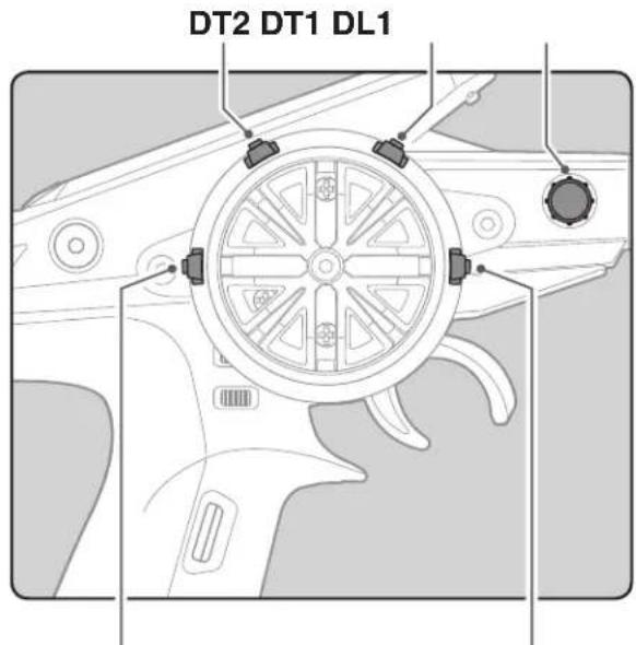

DT3 DT5 DT6DT4
| Set table functions (DL1, DT1/DT2/DT3/DT4/DT5/DT6) | |
| Abbreviation used on setup screen | Function name, etc |
| D/R Dual rate function | |
| ATL ATL function | |
| EXP-ST Steering EXP | |
| EXP-FW Throttle EXP (Forward side) | |
| EXP-BK Throttle EXP (Brake side) | |
| SPD-TN Steering speed (Turn side) | |
| SPD-RN | Steering speed (Return side) |
| ABS.PS A.B. | S. function (Return amount) |
| ABS.DL | A.B.S. function (Delay) |
| CYCLE | A.B.S. function (cycle speed) |
| ACC-FW | Throttle acceleration (Forward side) |
| ACC-BK Throttle acceleration (Brake side) | |
| TH-SPD Throttle speed | |
| ST-TRM Steering trim | |
| TH-TRM | Throttle trim |
| CH3 | Channel 3 |
| CH4 | Channel 4 |
| SUBTR1 | Sub trim (CH1) |
| SUBTR2 | Sub trim (CH2) |
| SUBTR3 | Sub trim (CH3) |
| SUBTR4 | Sub trim (CH4) |
| IDLE | Idle up function |
| ESC-RT Dual ESC mixing (4ch ESC rate) | |
| TH-OFF | Throttle off (engine cut) |
| PMX-A | Program mixing (RGHT/BRAK/DOWN sides) |
| PMX-B | Program mixing (LEFT/FWRD/UP sides) |
| BK3-RT | Brake mixing (3ch brake rate) |
| BK4-RT | Brake mixing (4th brake rate) |
| 4WS-RT | 4WS mixing (3ch steering rate) |
| ESC-MD | Dual ESC mixing (Drive mode select) |
| GYRO | Gyro mixing (Gain rate) |
| ACKMAN | Ackermann mixing (ackermann rate) |
| OFF | Not used |
Relationship between set value and step amount
(Setting range: 1\~10, 20, 30, 40, 50, 100, 2P)
-Steering trim/throttle trim
When set to the minimum "1", the total trim operating width is 200 clicks. For "100", the total operating width is 2 clicks and for 2P, the total operating width is 1 click.
-Rate, etc. setting
This is the % value which is operated by 1 click relative to the set value of each rate. Since the total operating width of functions having a rate of -100\~0\~+100 is 200%, when set to "100", the total operating width is 2 clicks. Since the total operating width of functions with a 0\~100 rate is 100%, "100" and 2P are operated by 1 click.
-Channel 3/4
When set to the minimum "1", the total operating width of channel 3 is 200 clicks. For "100", the total operating with is 2 clicks and 2P is operated by 1 click.
Select Switch Function "SWITCH"
Selection of the function to be performed by the switches (PS1, PS2).
- PS2 alternate operation (operation which switches between ON and OFF each time the switch is pressed) is possible.
NOR (Normal) -ON only while pressed, OFF when released.
ALT (Alternate) -Switched between ON and OFF each time pressed. - PS1 ON/OFF direction can be reversed (NOR/REV).
Display "SWITCH" screen using the following method:
![graph TD A["(HOME screen)"] --> B[" press "] B --> C["(MENU 1)"] C --> D[" (MENU 2) "] D --> E[" (SWITCH screen) "] E --> F[" press "] F --> G[" (SWITCH screen) "] subgraph HOMA H1["TH 83:00.00<br>No 1 S-4<br>MODEL-9301<br>1FH-NK6HT2<br>ST<br>T<br>S<br>D<br>R<br>G<br>E"] H2["0.00 S+10<br>CH<br>C"] H…](/content/2026/07/1455774/images/99a5a8cb2d9a9aa3cc2b36610ca484b11306a78ee5e596bb6130a100d369d7a0.jpg)
Function select switch setting
1 (Setting switch selection)
Select the switch you want to set by moving the (JOG) button up or down.
2 (Function setting)
Select the function with the (+) or (-) button.
- Refer to the list on the next page for the abbreviations of the functions.
(Changing the PS1 operation direction)
Select "DIRECTION" of "PS1" by moving the (JOG) button up or down. Select REV or NOR with the (+) or (-) button.
(Changing the PS2 operation system)
Select "DIRECTION" of "PS2" by moving the (JOG) button up or down. Select ALT or NOR with the (+) or (-) button.

*Function selection
Select button
- Select with the (+) or (-) buttons.
Adjustment buttons
- Use the (+) and (-) buttons to make adjustments.
- Return to the initial value by pressing the (+) and (-) buttons simultaneously (approx. 1 sec).
PS1 ON/OFF direction
PS2 alternate operation
3 When finished with setting, return to the MENU screen by pressing the (END) button.
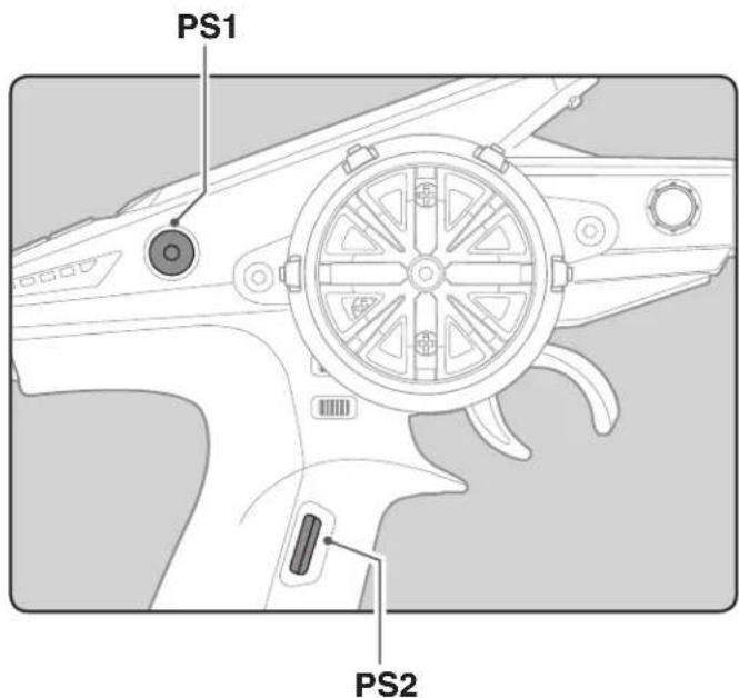
| Set table functions (PS1) | |
| Abbreviation used on setup screen | Function name, etc |
| NT-BRK Neutral brake function ON/OFF | |
| ABS A.B.S function ON/OFF | |
| IDLE Idle up function ON/OFF | |
| PRGMIX Program mixing function ON/OFF | |
| TH-OFF | Throttle off (engine cut) function ON/OFF |
| CH3 channel 3 | |
| CH4 channel 4 | |
| GYRO Switching GYRO mode | |
| OFF Not used | |
| Set table functions (PS2) | |
| Abbreviation used on setup screen | Function name, etc |
| NT-BRK Neutral brake function ON/OFF | |
| ABS A.B.S function ON/OFF | |
| IDLE Idle up function ON/OFF | |
| PRGMIX Program mixing function ON/OFF | |
| TH-OFF | Throttle off (engine cut) function ON/OFF |
| CH3 channel 3 | |
| CH4 channel 4 | |
| GYRO Switching GYRO mode | |
| 4WS 4WS mixing type select | |
| TIMER Timer function start/stop | |
| LOGGER Telemetry log start/stop | |
| OFF Not used | |
Steering Mixing "STR MIX"
(Steering, 4th channel system)
This mixing function uses 2 servos to individually control the left and right steering. Left and right steering can be set independently so smooth cornering is possible.
The right side steering servo or the left side steering servo connects to receiver CH1 and the other side connects to receiver CH4. The channel to which the left and right servo connects is not specified. After the left and right servos are adjusted individually, Ackerman can also be adjusted by Ackerman rate.
Setting Special mixings
When the 4th CH is set to ACT by BRAKE MIX (p.76), or when DUAL ESC (p.82) and CPS MIX (p.86) are used, this steering mixing function cannot be used.

Display "STR MIX" screen using the following method:
![graph TD A["(HOME screen)"] --> B[" press "] B --> C["(MENU 1)"] C --> D[" (MENU 2) "] D --> E[" Select "STR MIX " "] E --> F[" Press "] F --> G["(STR-MIX screen)"] G --> H[" (STR-MIX MODE: ACT +ACKERMANN *STR1 LFT 100 RGT 100 *STR2 LFT 100 RGT 100 "] H --> I[" (STR-MIX MODE: ACT +ACKERMAN…](/content/2026/07/1455774/images/63d6fab78f8b47b1e0fc846be47c4dfe34b7d18d97670fab26ac57810ce5e3ec.jpg)
Setup items
MODE :Function ON/OFF
STR1 LFT :Steering 1 Left side
STR1 RGT:Steering 1 Right side
STR2 LFT :Steering 2 Left side
STR2 RGT : Steering 2 Right side
Steering mixing adjustment
1 (Steering mixing function ON/OFF)
Select the setting item "MODE" by moving the (JOG) button up or down. Set the function by pressing the (+) or (-) button.
"INH": Function OFF.
"ACT": Function ON.
- When "(ESC>INH)" is displayed, the STR MIX cannot be used if the DUAL ESC function is not set to "INH".
- When "(CPS>INH)" is displayed, the STR MIX cannot be used if the CPS function is not set to "INH".
- When "(BRK4>INH)" is displayed, the STR MIX cannot be used if the BRAKE MIX (CH4) function is not set to "INH".
2 (Steering 1 rate)
Select the setting item STR 1 "LFT" or "RGT" by moving the (JOG) button up or down. Adjust the left and right steering amounts using the (+) or (-) button.
3 (Steering 2 rate)
Select the setting item STR 2 "LFT" or "RGT" by moving the (JOG) button up or down. Adjust the left and right steering amounts using the (+) or (-) button.
4 (Ackerman adjustment)
Select the setting item "ACKERMANN" rate by moving the (JOG) button up or down.
Adjust the left and right differential amount and adjust the Ackerman by (+) and (-) button.
5 When finished with setting, return to the MENU screen by pressing the (END) button.
Dial / Trim Setting
Ackerman rate can be controlled with digital dial or digital trim, using the function select trim dial function (See page 70).
Function ON/OFF (MODE)
INH, ACT
Select button
- Select with the (+) or (-) buttons.
Sterring 1 rate
(STR 1 LFT,RGT)
0\~120
Initial value:100
Adjustment buttons
- Use the (+) and (-) buttons to make adjustments.
- Return to the initial value by pressing the (+) and (-) buttons simultaneously (approx. 1 sec).
Sterring 2 rate
(STR 2 LFT,RGT)
0\~120
Initial value:100
Adjustment buttons
- Use the (+) and (-) buttons to make adjustments.
- Return to the initial value by pressing the (+) and (-) buttons simultaneously (approx. 1 sec).
Ackerman rate
-100 \~ 0 \~ +100
Initial value:0
Adjustment buttons
- Use the (+) and (-) buttons to make adjustments.
- Return to the initial value by pressing the (+) and (-) buttons simultaneously (approx. 1 sec).

Brake Mixing "BRAKE MIX" (Throttle, 3rd /4th channel system)
This function is used when the front and rear brakes must be adjusted independently such as on a 1/5 scale GP car. This mixing uses the 2nd CH for the rear brakes and the 3rd or 4th CH for the front brakes, or controls the front brakes with the 3rd CH and 4th CH servos, or controls the 2nd CH by independent throttle and controls the rear and front brakes with the 3rd CH and 4th CH.
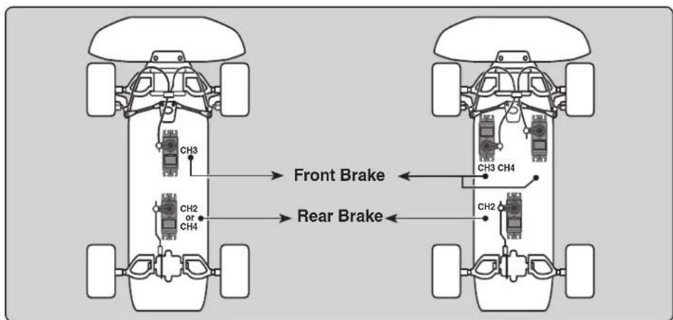
Operation
-When braking, mixing is applied to 2nd CH→3rd CH, 4th CH.
-3rd CH and 4th CH brake amount, 2nd CH, 3rd CH, and 4th CH brake delay, and 3rd CH and 4th CH brake ABS can be set.
CH3/4 brake ABS function
The ABS function can be used independently at the CH3 and CH4 sides even when the CH2 side ABS function is OFF. The amount of pumping speed (CYCL), operation point (TG.P), and duty ratio (DUTY) can be set in common with the CH2 side ABS function. (CH3 and CH4 brake return (AB.P) is fixed at 50.)
Display "BRAKE MIX" screen using the following method:
![graph TD A["(HOME screen)"] --> B[" press "] B --> C["END"] C --> D["(MENU 1)"] D --> E[" > STR MIX "] E --> F[" > BRAKE MIX "] F --> G[" > CYRO MIX "] G --> H[" > PROG MIX "] H --> I[" > DUAL ESC "] I --> J[" > 4WS "] J --> K[" > CPS MIX "] K --> L[" > TH MODE "] L --> M[" > CH3/CH4 "] M --> N[" >…](/content/2026/07/1455774/images/5bcc7ab785447242ee0b5fdb005bc29914b71f9e5e26681450b074a02166cc07.jpg)
Brake mixing adjustment
1 (Brake mixing function ON/OFF)
Select the setting item "MODE" of
"INH": Function OFF. "ACT": Function ON.
- When "(4WS>OFF)" is displayed below
2 (Brake rate)
Moving the (JOG) button up or down, select "RATE" of
3 (Delay amount setup)
Moving the (JOG) button up or down, select "DELY" of
"0": No delay. "100": Maximum delay amount.
4 (3rd & 4th channels brake-A.B.S ON/OFF)
Moving the (JOG) button up or down, select "ABS" of
5 When finished with setting, return to the MENU screen by pressing the (END) button.
Function ON/OFF (MODE) INH, ACT
Select button
- Select with the (+) or (-) buttons.
Brake rate (RATE)
0 \~ 100 Initial value:100
Adjustment buttons
- Use the (+) and (-) buttons to make adjustments. - Return to the initial value by pressing the (+) and (-) buttons simultaneously (approx. 1 sec).
Delay amount (DELY)
(CH3) 0 \~ 100 (CH4) 0 \~ 100 (CH2) 0 \~ 100 Initial value:0
Function ON/OFF (ABS) INH, ACT
Select button
- Select with the (+) or (-) buttons.
Setting Special Mixes
In order to use 3CH of the brake mixing function, it is necessary to set 4WS (p.80) and Gyro MIX (p.84) to the "INH" setting. In order to use 4CH, it is necessary to set STR MIX (p.74), Dual ESC (p.82) and CPS MIX (p.86) to the "INH" setting.
Dial / Trim Setting
The function select dial function can control the 3rd/4th channels brake rate (RATE) can be controlled with digital dial or digital trim, using the function select trim dial function (See page 70).
Programmable Mixing "PROG MIX"
(All channels)
This function allows you to apply mixing between steering, throttle, channel 3 and channel 4.
Additional Functions
-When the steering or throttle channel is the master channel (channel that applies mixing), trim data can be added (Trim mode).
- The mixing mode selection (Master mixing mode).
Relating function
steering :EPA, STR EXP, D/R, SPEED, 4WS
throttle :EPA, THR EXP, ATL, ABS, SPEED, BRAKE MIX, NT-BRK, ESC MIX, TH ACCEL
Movement of the slave channel side
The movement of the master channel side will be added to the movement of the slave channel side.
Display "PROG MIX" screen using the following method:
![graph TD A["(HOME screen)"] --> B[" press "] B --> C["END"] C --> D["Menu 1"] D --> E["Menu 2"] E --> F["PROG MIX screen"] F --> G["Press "] G --> H["END"] H --> I["Menu 3"] I --> J["Menu 3"] J --> K["Select "PROG MIX""] K --> L["PROG MIX MODE: INH LEFT: +100 RIGHT: +100 MST : STR SLV : CH…](/content/2026/07/1455774/images/dca774a0db30764e9db958f80c28e7c1ae46950f2965947c51fdd3a86c30a1fa.jpg)
Setup items
MODE : Function ON/OFF
LEFT : Mixing rate (Left side)
RGHT : Mixing rate (Right side)
MST : Master channel
SLV : Slave channel
MXMD : Mix mode
TRIM : Trim mode
Program mixing adjustment
(Preparation)
- When "PROG MIX" is turned ON and OFF by switch, set the switch by select switch function (p.72).
Function SW
PROGMIX
1 (Mixing function ON/OFF)
Select the setting item "MODE" by moving the (JOG) button up or down. Use the (+) or (-) and set the function to the "ON" or "OFF" state.
"INH": Function OFF.
"ON": Function ON. When the switch is OFF, "OFF" is displayed.
Function ON/OFF (MODE)
INH,ON (OFF)
Select button
- Select with the (+) or (-) buttons.
2 (Master channel)
Select setup item "MST" by moving the (JOG) button up or down, and select the master channel by pressing the (+) or (-) button.
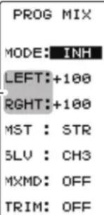
Program mixing function
3 (Slave channel)
Select setup item "SLV" by moving the (JOG) button up or down, and select the slave channel by pressing the (+) or (-) button.
4 (Upper side mixing amount adjustment)
Select the setting item upper side (See an upper figure) by moving the (JOG) button up or down. Use the (+) or (-) button and adjust the upper side mixing amount.
5 (Lower side mixing amount adjustment)
Select the setting item lower side (See an upper figure) by moving the (JOG) button up or down. Use the (+) or (-) button and adjust the lower side mixing amount.
6 (Mixing mode setup)
Select setup item "MXMD" by moving the (JOG) button up or down, and use the (+) or (-) button to select the mixing mode.
"OFF": Mixing proportional to master channel operation.
"MIX": Mixing by master channel another function considered.
7 (Trim mode setup)
Select setup item "TRIM" by moving the (JOG) button up or down, and use the (+) or (-) button to select the mixing mode.
"OFF": Trim is removed.
"ON": Trim is added.
8 When fi nished with setting, return to the MENU screen by pressing the (END) button.
Channel selection (MST)
STR, THR, CH3, CH4
Initial value: STR
Select button
- Select with the (+) or (-) buttons.
Channel selection (SLV)
STR, THR, CH3, CH4
Initial value: CH3
Select button
- Select with the (+) or (-) buttons.
Mixing amount
-120\~0\~+120
Initial value: +100
Adjustment buttons
- Use the (+) and (-) buttons to
make adjustments.
- Return to the initial value by pressing the (+) and (-) buttons simultaneously (approx. 1 sec).
Mixing amount
-120\~0\~+120
Initial value: +100
Mixing mode (MXD)
OFF, ON
Initial value: OFF
Select button
- Select with the (+) or (-) buttons.
Trim mode (TRIM)
OFF, ON
Initial value: OFF
Select button
- Select with the (+) or (-) buttons.
Switch / Dial / Trim Setting
When the program mixing function ON/OFF by switch, use the function select switch function (see page 72). Mixing rate (RATE) can be controlled with digital dial or digital trim, using the function select trim dial function (see page 70).
This function can be used with crawlers and other 4WS type vehicles. It is mixing which uses the 1st CH to control the front side steering and the 3rd CH to control the rear side steering.
OFF (front side only), reverse phase, same phase, rear side only and other 4WS type switching is used by selecting PS2 with the function select switch function (p.72). If not selected,
Setting Special Mixes
When the 3rd CH was set to ACT at Brake Mixing (p.76) or when Gyro Mixing (p.84) is used, 4WS Mixing cannot be used.
Display "4WS" screen using the following method:
![graph TD A["(HOME screen)"] --> B[" press "] B --> C["(MENU 1)"] C --> D["Menu 2"] D --> E["4WS screen"] E --> F["Press "] F --> G["END"] G --> H["(MENU 3)"] H --> I["Menu 3"] I --> J["4WS screen"] style A fill:#f9f,stroke:#333 style B fill:#ccf,stroke:#333 style C fill:#cfc,stroke:#333 style D fill…](/content/2026/07/1455774/images/1dd03c9b3cd9800e2393bcea1f6e5ec42b3c8ad40f5816b5da3ee4cc6935b4aa.jpg)
![graph TD A["Same phase Reverse phase Rear side only"] --> B["Front side only (4WS OFF)"] A --> C["Side side only"] A --> D["Side side only"] A --> E["Side side only"] A --> F["Side side only"] A --> G["Side side only"] A --> H["Side side only"] A --> I["Side side only"] A --> J["Side side only"] A -…](/content/2026/07/1455774/images/ea8b699be05c478d28709815173bd27c9526ae987fbe51ea56d8d77049d94e30.jpg)
4WS mixing adjustment
(Preparation)
Since this function is used by switching the type of 4WS with a switch (PS2), the switch used by the function select switch function (page 72) is set.
Setup items
MODE : 4WS Type
RATE : 3ch rate (Rear side)
MXMD : Mix mode
Function SW
4WS
1 (4WS type selection)
Select the setting item "MODE" by moving the (JOG) button up or down. Use the (+) or (-) and set the function to the "ON" or "OFF" state.
"INH": Function OFF (front only).
"2TYP": Front side only, reverse phase switching.
"3TYP": Front side only, reverse phase and same phase switching.
"4TYP": Front side only, reverse phase, same phase, and rear side only switching.
- When "(GYRO MIX ACT → INH)" is displayed, the 4WS cannot be used if the GYRO MIX function is not set to "INH".
- When "(BRAKE CH3 ACT → INH)" is displayed, the 4WS cannot be used if the BRAKE MIX (CH3) function is not set to "INH".
Switched in the order shown in the figure below by set SW (PS2)

Function ON/OFF (MODE)
- Select with the (+) or (-) buttons.

"2TYP": Front side only and reverse phase switching
![graph LR A["4WS MODE: 3TYP RATE: 100 MXMD: OFF ▶SWITCH"] --> B["4WS MODE: 3TYP RATE: 100 MXMD: OFF ▶SWITCH"] B --> C["4WS MODE: 3TYP RATE: 100 MXMD: OFF ▶SWITCH"] C --> D["Output"]](/content/2026/07/1455774/images/98e59c896590333d3df04e7c68665f791a49ea1c705cb67e1f16fb1a54504a50.jpg)
"3TYP": Front side only, reverse phase, and same phase switching
![graph LR A["4WS<br>MODE: 4TYP<br>RATE: 100<br>MXMD: OFF<br>▶SWITCH"] --> B["4WS<br>MODE: 4TYP<br>RATE: 100<br>MXMD: OFF<br>▶SWITCH"] B --> C["4WS<br>MODE: 4TYP<br>RATE: 100<br>MXMD: OFF<br>▶SWITCH"] C --> D["4WS<br>MODE: 4TYP<br>RATE: 100<br>MXMD: OFF<br>▶SWITCH"] D --> E["End"]](/content/2026/07/1455774/images/612e5156c649616d32f2773ba5a09e8a5802caf6628b03a951d400179ad10e6d.jpg)
"4TYP": Front side only, reverse phase, same phase, and rear side only switching
2 (Rear side travel adjustment)
Select setting item "RATE" by moving the (JOG) button up or down. Adjust the rear side travel with the (+) or (-) button.
3 (Mix mode setting)
Select setting item "MXMD" by moving the (JOG) button up or down. Set the mix mode with the (+) or (-) button.
"OFF": The EXP function of the 1st CH and other settings are not mixed.
"ON": The EXP function o the 1st CH and other settings are mixed.
4 When finished with setting, return to the MENU screen by pressing the (END) button.
Rear rate (RATE)
0 \~ 100
Initial value:100
Adjustment buttons
- Use the (+) and (-) buttons to make adjustments.
- Return to the initial value by pressing the (+) and (-) buttons simultaneously (approx. 1 sec).
Mixing mode (MXMD)
OFF, ON
Initial value: OFF
Select button
- Select with the (+) or (-) buttons.
Dual ESC Mixing "DUAL ESC"
(Throttle system)
This function is mixing used with crawlers and other 4WD type vehicles and uses the 2nd CH to control the front motor controller and the 4th CH to control the rear motor controller.
Front drive only, rear drive only, or both front and rear drive can be selected using any programmed DT (digital trim) button.
Setting Special Mixes
When the 4th CH is set to ACT by Brake Mixing (p.76), or when Steering mixing (p.74) and CPS Mixing (p.86) are used, this dual ESC Mixing function cannot be used.
Display "DUAL ESC" screen using the following method:.
![graph TD A["(HOME screen)"] --> B["END"] B --> C["(MENU 1)"] C --> D["NOT"] D --> E["NOT"] E --> F["NOT"] F --> G["NOT"] G --> H["NOT"] H --> I["NOT"] I --> J["NOT"] J --> K["NOT"] K --> L["NOT"] L --> M["NOT"] M --> N["NOT"] N --> O["NOT"] O --> P["NOT"] P --> Q["NOT"] Q --> R["NOT"] R --> S["NOT"]…](/content/2026/07/1455774/images/d6b48090e24fd6fa3528f007046a40542b820b9908014bf3bd9fb51cc9f478be.jpg)
Dual ESC mixing adjustment
(Preparation)
- This function is used to switch between front drive/4WD/rear drive using one of the trims (dial). Set the desired trims (dial) for this function using the TRIM DIAL screen (p.70).
- DT1 through DT6 or DL1.
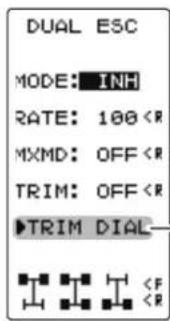
2 (Rear side travel adjustment)
Select the setting item "RATE" by moving the (JOG) button up or down. Use when applying a rotation difference to the front and rear wheels by adjusting the rear (CH4) motor controller travel with the (+) or (-) button.3 (Mix mode setting)
Select the setting item "MXMD" by moving the (JOG) button up or down. Set the mix mode with the (+) or (-) button. "OFF": CH2 EXP function and other settings are not mixed. "ON": CH2 EXP function and other settings are mixed.4 (Trim mode setting)
Select the setting item "TRIM" by moving the (JOG) button up or down. Set the trim mode with the (+) or (-) button. "OFF": Front side (CH2) trim data is not included. "ON": Front side (CH2) trim data is included.5 When finished with setting, return to the MENU screen by pressing the (END) button.
Rear rate (RATE)
0 \~ 120 Initial value:100Adjustment buttons
- Use the (+) and (-) buttons to make adjustments. - Return to the initial value by pressing the (+) and (-) buttons simultaneously (approx. 1 sec).Mixing mode (MXMD)
OFF, ON Initial value: OFFSelect button
\- Select with the (+) or (-) buttons.Trim mode (TRIM)
OFF, ON Initial value: OFFSelect button
\- Select with the (+) or (-) buttons.Dial / Trim Setting
The function select dial function can control the 4th channel's ESC (Rear side) rate (RATE) with digital dial or digital trim, using the function select trim dial function (See page 70).Note:
As this function drives 2 separate motor controllers simultaneously, a applied. Use this function carefully so that the motor controllers are not damaged. Futaba will not be responsible for motor controller, motor, and other vehicle trouble due to use of this function.Gyro Mixing "GYRO MIX"
(Steering system)
This function is a remote gain function which adjusts the sensitivity of the Futaba car rate gyro at the T4PV side, and is mixing that uses the 3rd CH to adjust the gyro sensitivity. When using the T4PV by switching the AVCS and normal modes, use PS1 or PS2 with the function select switch function (p.72). For a description of the car rate gyro mounting method and handling, refer to the rate gyro instruction manual.Setting Special Mixes
When the 3rd CH was set to ACT at Brake Mixing (p.76) or when 4WS Mixing (p.80) is used, Gyro mixing cannot be used.Dial / Trim Setting
The gain amount can be adjusted by using the function trim dial function (p.70). Display "GYRO MIX" screen using the following method: AVCS / NORMAL Modes
The gyro has 2 operating modes: NORMAL mode and AVCS mode. In the AVCS mode, the angle is controlled simultaneously with NORMAL mode rate control (swing speed). The AVCS mode increases straight running stability more than that of the NORMAL mode. Because the feel of operation is different, choose your favorite mode. Gyro mixing adjustment
(Preparation)
- Refer to the gyro instruction manual and connect the gyro to the receiver. When using remote gain, connect gyro sensitivity adjustment to the 3rd CH of the receiver. - When using gyro mixing by switching between the NORM (normal) and AVCS modes, use the function select switch function (p.72) to set the switch to be used.Setup items
MODE : Gyro mode NORM : Normal mode gain AVCS :AVCS mode gainFunction SW
GYRO1 (Gyro mixing setting)
Select the setting item "MODE" by moving the (JOG) button up or down. Set the function by pressing the (+) or (-) button. "INH": Function OFF. "NORM": NORMAL mode gain. "AVCS": AVCS mode gain. "SEL": Switching Normal mode and AVCS mode. (DisplayedFunction selection (MODE)
INH, NORM, AVCS, SELSelect button
\- Select with the (+) or (-) buttons.     "SELE" mode "NORM" mode "AVCS" mode The function select switch screen (p.72) can be displayed from this screen.2 (NORMAL side gain adjustment)
Select the setting item "NORM" by moving the (JOG) button up or down. Adjust the NORMAL side gain with the (+) or (-) button. (AVCS side gain adjustment) Select the setting item "AVCS" by moving the (JOG) button up or down. Adjust the AVCS side gain with the (+) or (-) button.3 When fi nished with setting, return to the MENU screen by pressing the (END) button.
NORMAL / AVCS gain
(NORM / AVCS) 0 \~ 120 Initial value:30Adjustment buttons
- Use the (+) and (-) buttons to make adjustments. - Return to the initial value by pressing the (+) and (-) buttons simultaneously (approx. 1 sec).CPS Mixing "CPS MIX"
This function controls the Futaba CPS-1 channel power switch. Normally, when using the CPS-1 unit to operate vehicle lighting systems, the CPS-1 unit with LED connected is connected to a vacant switch channel and the LEDs are turned on and off by switch while the vehicle is running. However, when the CPS-1 mixing (CPS MIX) function is used, the LED can be turned on and off and flashed in step with steering and throttle operation, as well as being turned on and off by switch. The flashing speed (cycle) can also be set. For instance, the LED can be flashed as a brake light by throttle brake side operation.Setting Special Mixes
When the 4th CH is set to ACT by Brake Mixing (p.76), or when Steering Mixing (p.74) and Dual ESC Mixing (p.82) are used, this CPS Mixing function cannot be used. Display "CPS MIX" screen using the following method: Setup items
MODE : Function ON/OFF, control mode POSI : ON/OFF position TYPE : ON/OFF type TCYCL : Flashing speedCPS mixing adjustment
(Preparation) - Connect the CPS-1 to the 4th CH of the receiver. - When the LEDs are turned on and off by switch, use the function select switch function (p.72) to set the switch to be used. Function SW CH41 (Control system setup)
Select the setting item "CTRL" by moving the (JOG) button up or down. Use the (+) or (-) button and select the function. "INH": Function OFF. "CH4 FUNC" : ON/OFF by switch set at the 4th CH. "STR NT": ON at steering neutral. "STR END": ON at both sides of steering. "THR NT": ON at throttle neutral. "THR FWD": ON at throttle forward side. "THR BRK": ON at throttle back (brake) side. "TH NT+BK": ON at throttle neutral and back (brake) sides. \- When "(ESC MIXACT → INH)" is displayed, the CPC MIX cannot be used if the DUAL ESC function is not set to "INH". \- When "(STR MIX ACT → INH)" is displayed, the CPS MIX cannot be used if the STR MIX function is not set to "INH". \- When "(BRK4> ACT → INH)" is displayed, the CPS MIX cannot be used if the BRAKE MIX (CH4) function is not set to "INH".2 (ON/OFF switching position selection)
Select the setting item "POSI" by moving the (JOG) button up or down. Use the (+) or (-) button and select the ON/OFF position. Since the ON/OFF state is displayed at the right side of the setting item "CTRL", setting can be confirmed while operating the function to be controlled (for example, throttle). Function selection (MODE)
INH, CH4 FUNC, STR NT, STR END, THR NT, THR FWD, THR BRK, TH NT+BKSelect button
\- Select with the (+) or (-) buttons.3 (ON/OFF type setup)
Select the setting item "TYPE" by moving the (JOG) button up or down. Use the (+) or (-) button and select the type of LED lighting. Normal ON/Off type or fl ashing can be selected. "NORMAL" : Normal ON/OFF type. "FLASH": Flashing display.4 (Flashing cycle setting)
When flashing type "FLASH" is selected at the setting item "TYPE", the flashing speed (cycle) can be set. Select the setting item "CYCL" by moving the (JOG) button up or down. Use the (+) or (-) button and select the flashing speed (cycle).5 When finished with setting, return to the MENU screen by pressing the (END) button.
Function selection (TYPE)
NORMAL, FLASHSelect button
\- Select with the (+) or (-) buttons.Flashing cycle (CYCL)
1 \~ 100 Initial value: 50Adjust button
- Use the (+) and (-) buttons to make adjustments. - Return to the initial value by pressing the (+) and (-) buttons simultaneously (approx. 1 sec).Throttle Mode "TH MODE"
(Throttle system)
This menu has the following 4 functions: - Servo neutral mode, which sets the throttle neutral ratio to 7:3 or 5:5. - Idle up, which raises the idling speed when starting the engine to improve engine starting performance of a gasoline car (boat). - Neutral brake, which applies the brakes at the neutral position of the throttle trigger. - Throttle off (engine cut), which stops the engine of a boat, etc. by operating the throttle servo to the low side regardless of the position of the throttle trigger. Display "TH MODE" screen using the following method:  Setup items SXNT : Throttle servo neutral position IDLUP : Idle-Up rate NTBRK : Neutral brake rate THOFF : Throttle off (engine cut) positionThrottle servo neutral position "SXNT"
-This function allows selection of the forward side and brake (reverse) side operation ratio from 7:3 or 5:5 by changing the neutral position of the throttle servo.  Selecting the throttle servo neutral position
1 (Mode selection)
Select the setting item "SXNT" by moving the (JOG) button up or down. Select "F5/B5" or "F7/B3" by (+) or (-) button. "F5/B5" = Forward 50% : Back50%. "F7/B3" = Forward 70% : Back30%. Mode selection (SXNT) F5/B5, F7/B3Select button
\- Select with the (+) or (-) buttons. 2 When finished with setting, return to the MENU screen by pressing the (END) button. This is a function select switch function. The idle up switch must be set (see page 72). This function is used to improve engine starting performance by raising the idling speed when starting the engine of a GP car (boat). It is also effective when you want to prevent the braking when the power is turned off during running, due to the effect of your gear ratio setting and choice of motor when operating an electronic car. However, considering safety, and to prevent the motor from rotating instantly when the power is turned on, the MC950CR, MC851C, MC602C, MC402CR, and other Futaba electronic motor speed controller (ESC) will not enter the operation mode if the neutral position is not confirmed. When using the MC950CR, MC851C, MC602C, MC402CR, or other Futaba ESC, confirm that the ESC is in the neutral position and the set is in the operation mode before setting the idle up function switch to ON.Operation
The throttle neutral position is offset to the forward side or brake side. There is no linkage locking, etc. because there is no change near the maximum operation angle even when the neutral position is offset by this function.Operation Display
While this function is ON, the LED blinks.  If the power switch is turned on while the idle-up switch is on, an audible alarm will be heard. Immediately set the Idle-Up switch to OFF. Idle-Up function adjustment
(Preparation) \- Use the function select switch to select the switch. (p.72) 1 (Idle-Up rate) Select the setting item "IDLUP" by moving the (JOG) button up or down. Use the (+) and (-) buttons to set the Idle-Up rate. 2 When finished with setting, return to the MENU screen by pressing the (END) button.Adjust button
- Adjust with the (+) and (-) buttons. - Return to the initial value by pressing the (+) and (-) buttons simultaneously (approx. 1 sec). Idle-Up rate (IDLUP) D50 \~ D1, 0, U1 \~ U50 Initial value: 0 "D": Brake side "U": Forward sideDial / Trim Setting
The function select dial function can control the Idle-up rate with digital dial or digital trim (See page 70). This is a function select switch function. The neutral brake function ON/OFF switch must be set (see page 72). The neutral brake, which applies the brakes at the neutral position of the throttle trigger, can be set. However, when using the MC950CR, MC851C, MC602C, MC402CR, or other Futa-ba ESC, confirm that the ESC is in the neutral position and the set is in the operation mode before setting the neutral brake function switch to ON, the same as the idle up function (p.81). In addition, when the idle up function or throttle off function (p.91) is set, this function has a higher priority than the neutral brake function.Reference
The ESC neutral brake function and T4PV neutral brake function can be used simultaneously. However, when setting is difficult to understand, we recommend that only one neutral brake function be used.Dial / Trim Setting
When the neutral brake function is "ON", the neutral brake rate adjustment is automatically assigned to the throttle trim (DT1 - DT6 or DL1).Operation display
An LED blinks while the neutral brake function is active.  If the power switch is turned on while the neutral brake switch is on, an audible alarm will be heard. Immediately set the neutral brake switch to OFF.  Warning displayNeutral Brake function adjustment
(Preparation) \- Use the function select switch to select the switch. (p.72) 1 (Neutral brake rate) Select the setting item "NTBRK" by moving the (JOG) button up or down. Use the (+) and (-) buttons to set the neutral brake rate. 2 When finished with setting, return to the MENU screen by pressing the (END) button.Adjust button
- Adjust with the (+) and (-) buttons. - Return to the initial value "0" by pressing the (+) and (-) buttons simultaneously for about 1 second. Brake rate (NTBRK) 0 \~ B100 Initial value: 0Effect of set value of other functions on neutral brake
Throttle side EPA function, or ATL function setting, also affects neutral brake side operation.Throttle Off (engine cut) "THOFF"
This is a function select switch function. The throttle off function ON/OFF switch must be set (see page 72). The engine cut function stops the engine of a boat, etc. by operating the throttle servo to the slow side by switch regardless of the position of the throttle trigger and the setting of other functions (reverse function setting is effective).Dial / Trim Setting
The function select dial function can control the throttle-off position can be controlled with digital dial or digital trim (See page 70).Operation display
An LED blinks while the neutral brake function is active.  If the power switch is turned on while the throttle-off switch is on, an audible alarm will be heard. Immediately set the throttle off switch to OFF. Engine Cut function adjustment
(Preparation) \- Use the function select switch to select the switch. (p.72) 1 (Preset position setup) \- Select the setting item "THOFF" by moving the (JOG) button up or down. Use the (+) and (-) buttons to set the preset position of the throttle servo. 2 When finished with setting, return to the MENU screen by pressing the (END) button.Adjust button
- Adjust with the (+) and (-) buttons. - Return to the initial value by pressing the (+) and (-) buttons simultaneously (approx. 1 sec). Preset position (THOFF) 0 \~ B100 Initial value: 0 Caution
Always operate carefully before using this function. While switch with preset function set is in the ON state, the servo (motor controller) is locked in the preset position and does not operate even if the throttle trigger is operated. If the servo is operated at the wrong setting, you may lose control of the car (boat).Channel 3/4 "CH3/CH4"
(3/4 channel)
The channel 3/4 servo position can be set from the this screen. When CH3/4 is assigned to a trim dial or switch by the trim dial function (p.70) or the switch function (p.72) this setting is linked to that. When CH3/4 is not assigned to a trim dial or switch, it can be set with this screen. When CH3/4 is assigned to a switch by the switch function, you cannot adjust CH3/4 via the screen. Display "CH3/CH4" screen using the following method: Rate/position adjustment on channel menu screen
1 (Function selection)
On each CH3/CH4 screen select CH3 "POSI" or CH4 "POSI" by moving the (JOG) button up or down.2 (Position setting/rate adjustment)
Use the (+) and (-) buttons to adjust the channel 3 or channel 4 position.3 When finished with setting, return to the MENU screen by pressing the (END) button.
Channel 3 position (POSI) Channel 4 position (POSI) 0\~100% Initial value: 0Adjust button
\- Adjust with the (+) and (-) buttons. \- Return to the initial value by pressing the (+) and (-) buttons simultaneously (approx. 1 sec).S.BUS Link Function "SX LINK"
This is a special function which allows Futaba S.BUS/S.BUS2 servo parameter changes to be set by the T4PV transmitter. However, some data changes require a PC and S-Link software. This function is used by connecting Futaba S.BUS/S.BUS2 servos directly to the transmitter. Use the various optional servo extension cords according to the distance between the transmitter and servo. -When the T4PV battery voltage drops, the display switches to low battery display. Therefore, use this function when there is ample battery capacity remaining. -Also connect the corresponding battery to the servo side.  Display to "SX LINK" screen using the following method:  Using the S.BUS servo function
(Preparation)
- Connect the T4PV and S.BUS or S.BUS2 servo in accordance with the connection diagram shown on page 93. - Connect the battery to S.BUS/S.BUS2 servo. 1 Display the SX LINK function screen referring on page 93. 2 (S.BUS/S.BUS2 servo read) Execute this function to read the connected servo's ID and the data currently set at the servo. Select the setting item "MODE" by moving the(JOG) button up or down. Select "READ" by (+) or (-) button, and press the (JOG) button. -"COMPLETE!" blinks on the screen and the servo ID and currently set contents are read. - If "COM-ERROR" blinks on the screen, communication with the servo is not being performed normally. Check the T4PV and servo connection and the battery connection to servo and repeat READ. 3 (Writing to S.BUS/S.BUS2) Execute this function to write the setting data to the servo. See pages 95\~96 for the setting data contents. Select the setting item "MODE" by moving the (JOG) button up or down. Select "WRITE" by (+) or (-) button, and press the (JOG) button. -"COMPLETE!" blinks on the screen and the setting data is written to the servo. -If "COM-ERROR" blinks on the screen, communication with the servo is not being performed normally. Check the T4PV and servo connection and the battery connection to ESC and the ESC power switch and repeat WRITE. In addition, if (NO DATA) is displayed on the T4PV screen, "WRITE" cannot be selected because there is no setting data to be written. 4 (Initialization) This function writes the servo setting data set at the factory to the connected servo. Perform "READ" before performing initialization. Select the setting item "MODE" by moving the (JOG) button up or down. Select "RESET" by (+) or (-) button, and press the (JOG) button. \- "COMPLETE!" blinks on the screen and the initial data is written to the servo. If "COM-ERROR" blinks, communication with the servo was not performed normally. Check the T4PV and servo connection and the battery connection to servo, and repeat RESET, when (NO DATA) is displayed on the T4PV screen"RESET" cannot be selected because there is no write initial data.         Servo function setup
1 Select the setting item by moving the (JOG) button. Set the value by (+) and (-) button.Setup item selection
\- Select by the (JOG) button. Adjustment buttons
- Use the (+) and (-) buttons to make adjustments. - Return to the initial value by pressing the (+) and (-) buttons simultaneously (approx. 1 sec).Setup item
ID
Displays the ID of the servo whose parameters are to be read. It cannot be changed.SMOT (Smoother)
This function makes servo operation smooth. Set it according to your taste. Normally set it to "ACT". Set it to "INH" when you want especially quick operation. When the smoother function is set to "ACT" and the servo is operated, the distance up to the target position is changed in steps so movement is smooth.DEAD (Dead band)
The dead band angle at stopping can be specified. [Relationship between dead band set value and servo operation] Small - Dead band angle is small and the servo is immediately operated by a small signal change. Large - Dead band angle is large and the servo does not operate at small signal changes. (Note) If the dead band angle is too small, the servo will operate continuously and the current consumption will increase and the life of the servo will be shortened. SX LINK DAMP (Damper)
The characteristic when the servo is stopped can be set. When smaller than the standard value, the characteristic becomes an overshoot characteristic. If the value is larger than the standard value, the brake is applied before the stop position. Especially, when a large load is applied, overshoot, etc. are suppressed by inertia and hunting may occur, depending on the conditions. If hunting (phenomena which cause the servo to oscillate) occurs even though the Dead Band, Stretcher, Boost and other parameters are suitable, adjust this parameter to a value larger than the initial value. [Relationship between damper set value and servo operation] Small - When you want to overshoot. Set so that hunting does not occur. Large - When you want to operate so that braking is not applied. However, it will feel like the servo response has worsened. (Note) If used in the hunting state, not only will the current consumption increase, but the life of the servo will also be shortened. ESC Link Function "MC LINK"
This is a special function which lets you set the contents of the Link software which performs Futaba electronic motor speed controller (ESC), MC960CR, MC940CR, MC-950CR, MC851C, MC602C, MC402CR, etc. variable frequency and other data changes at the T4PV transmitter. However, some data changes require a PC and Link software. This function is used by connecting the ESC directly to the transmitter. The T4 power switch is used at the display side. Use the various optional servo extension cords according to the distance between the transmitter and ESC. The last data read from ESC to T4PV or the last data written from T4PV to ESC is saved to the T4PV. Since the data for each model memory can be saved, the data of up to 40 models can be saved. -When the T4PV battery voltage drops, the display switches to low battery display. Therefore, use this function when there is ample battery capacity remaining. -Also connect the battery at the ESC side. -Note: Do not read to the T4PV an MC940/960CR whose speed was set to over 99990rpm by Link software side Boost Angle rpm setting.  Display to "MC LINK" screen using the following method: Using the ESC Link function
(Preparation) -Connect the T4PV and ESC in accordance with the connection diagram, and connect the battery to ESC.Setup item
READ :ESC's data read WRITE :Writing the data to ESC RESET :Initialization 1 Display the MC LINK function screen in the above manner. 2 (ESC read) Execute this function to read the connected ESC type and the data currently set at the ESC. To save the ESC data to the T4PV, rewrite the read data. When you want to write the data saved in the T4PV to an ESC of the same type, execute the following "WRITE"(write) without executing "READ"(read). Select the setting item "MODE" by moving the (JOG) button up or down. Select "READ" by (+) or (-) button, and press the (JOG) button. -"COMPLETE!" blinks on the screen and the ESC type and currently set contents are read. - If "COM-ERRORR" blinks on the screen, communication with the amp is not being performed normally. Check the T4PV and ESC connection and the battery connection to ESC and the ESC power switch and repeat READ.    MC402CR MC602C   MC851C MC950CR MC960CR MC940CR   3 (Writing to ESC)
Execute this function to write the setting data to ESC. See pages 99\~104 for the setting data contents. Select the setting item "MODE" by moving the (JOG) button up or down. Select "WRITE" by (+) or (-) button, and press the (JOG) button. - "COMPLETE!" blinks on the screen and the setting data is written to ESC. -If "COM-ERROR" blinks on the screen, communication with the amp is not being performed normally. Check the T4PV and ESC connection and the battery connection to ESC and the ESC power switch and repeat WRITE. In addition, if (NO DATA) is displayed on the T4PV screen, "WRITE" cannot be selected because there is no setting data to be written. - Different type ESC data cannot be written. If writing is attempted, "COM-ERROR" will link on the screen to show that the ESC type is wrong.4 (Initialization)
This function writes the ESC setting data set at the factory to the connected ESC and T4PV. Perform "READ" before performing initialization. Select the setting item "MODE" by moving the (JOG) button up or down. Select "RESET" by (+) or (-) button, and press the (JOG) button. \- "COMPLETE!" blinks on the screen and the initial data is written to the ESC. If "COMERROR" blinks, communication with the amp was not performed normally. Check the T4PV and ESC connection and the battery connection to ESC and the ESC power switch, and repeat RESET. In addition, when (NO DATA) is displayed on the T4PV screen"RESET" cannot be selected because there is no write initial data.      ESC function setup (MC601/602/850/851C/401/402/950CR)
1 Select the setting item by moving the (JOG) button up or down. Set the value by (+) and (-) button. Setup item selection \- Select by the (JOG) button.  Adjustment buttons - Use the (+) and (-) buttons to make adjustments. - Return to the initial value by pressing the (+) and (-) buttons simultaneously (approx. 1 sec).Setup item
MIn-(PWM FREC MIN LD) 100Hz\~10000Hz (10kHz) MC950CR:500Hz\~30000Hz (30kHz) Same as Link software PWM frequency (at Min. load). MIn sets the "0"A PWM frequency at minimum load. MAX-(PWM FREC MAX LD) 100Hz\~10000Hz (10kHz) MC950CR:500Hz\~30000Hz (30kHz) Same as Link software PWM frequency (at Max. load). MAX sets the PWM frequency at maximum load at the output current limit value set by Current Limiter. BRK-(PWM FREC BRK LD) nOR(2000Hz)/ HIG(1000Hz)/ SPH(500Hz) MC950CR:500Hz\~30000Hz (30kHz) Same as Link software Brake PWM at frequency. This setting can set the brake PWM frequency. nTB-(NEUTRAL BRAKE) 0%(OFF)\~100% Same as Link software Neutral Brake. Make this setting when you want to use the brakes at the neutral throttle (OFF) position by throttle operation. The larger this value, the greater the braking force. When you want to use the neutral brake, set this value to "0%". CLM-(CURRENT LIMIT) 50A\~300A (MC950CR:50A\~300A), OFF Same as Link software Current Limiter. Current Limiter sets the current value at maximum load here. Since setting of the MAX is based on the output current limit value set by Current Limiter, Current Limiter does not have to be turned OFF except when a current exceeding 300A is generated. "MIn", which sets the frequency when the load is small, is set to the high frequency side (large value) when extension is desired after straightaways and curves. "MAX", which sets the frequency when the load is large, is set to the high frequency side (large value) when you want to suppress the rise from low speed and when motor heating and commutator roughness are sensed. When the rise from low speed is poor, and becomes bad even when "MAX" is set to the low frequency side, use the log data to check if there was a momentary voltage drop. When you want to suppress the overall power, lengthen the run time, and otherwise improve efficiency, set both "MAX" and "MIn" to the high frequency side. When you want to set a fixed PWM frequency at full range regardless of the load current, set PWM frequency (at Max. load) and PWM frequency (at Min. load) to the same value.LBP-(LOW BATTERY VOLT) 2.5V\~6V 2.5V\~7.5V for MC950CR
Same as Link software Low Bat Protection. This setting cuts off the output to the motor when the running battery voltage drops to the set voltage to prevent the receiver from stopping operation when the supply of voltage to the receiver becomes insufficient while running due to a drop in the power supply voltage. When the power supply voltage recovers, power is supplied to the motor once more.DBA-(DEAD BAND) ±2μs\~±50μs
Same as Link software Dead Band. This sets the range (neutral point range) over which the ESC does not respond to transmitter throttle operation. The larger the set value, the wider this range.  CTM-(C.L. TIME LIMIT) 50A\~300A /CLT-(C.L. TIMER) 0sec(OFF)\~240sec (except MC950CR)
Same as Link software Current Limiter (Time Limit)/Current Limit timer. The output current can be limited up to the set time lapse from the start of running. This is effective in preventing the motor from outputting wasted energy when the voltage is high immediately after the power battery was recharged. - "CTM" (Time Limit) sets the maximum output current within the time the output current is limited. - "CLT" sets the time the output current is limited. This function is disabled when set to "0" sec. Since the Current Limit Timer starts when the throttle is operated to the forward side and current is output to the motor, this function begins to operate when the motor is run during trim adjustment, etc.FWB-(FORWARD BOOST) 0\~100 (except MC850C)
Same as Link software Forward Boost. Operation near the throttle trigger (stick) neutral position becomes a sharp rise. BMD-(BRAKE MAX DUTY) 0%\~100%
Same as Link software Brake Max. Duty. This setting can set the braking force between the neutral point and Max brake point. The larger this value, the greater the braking force. When set to "0%", the brakes are not effective.RMD-(REVERSE MAX DUTY) w/back only 0%\~100%
Same as Link software Reverse Max. Duty. This setting can set the reverse power between the neutral point and Max reverse point. The larger this value, the greater the reverse power. When set to "0%", the reverses are not effective. MC950CR only setup item
REV-(REV CANCEL) BRk /REV Same as Link software Reverse Cancel.
When set to BRk, reverse operation is not performed. LA-(LEAD ANGLE) 0\~1500 Same as Link software Lead Angle. The lead angle of the motor can be set at the MC950CR side. However, we recommend that it normally be set to "0". Since this setting is premised on setting by referring to the speed log by the Link software, independent use of the MC LINK function of the T4PV is recommended.ESC function setup (MC940CR, MC960CR)
1 Select the setting item by the (JOG) button up or down.
Set the value by (+) and (-) button. Operate the following (JOG) button and switch between Page 1 and Page 2 of the setup screen. Setup item selection \- Select by the (JOG) button.Adjustment buttons
- Use the (+) and (-) buttons to make adjustments. - Return to the initial value by pressing the (+) and (-) buttons simultaneously (approx. 1 sec). Setup item
Min-(PWM FREC MIN LD) 1kHz(1000Hz)\~30kHz (30000Hz) Same as Link software PWM frequency (at Min. load). MIn sets the "0"A PWM frequency at minimum load. MAX-(PWM FREC MAX LD) 1kHz(1000Hz)\~30kHz (30000Hz) Same as Link software PWM frequency (at Max. load). MAX sets the PWM frequency at maximum load at the output current limit value set by Current Limiter. BRK-(PWM FREC BRK LD) 1kHz(1000Hz)\~30kHz (30000Hz) Same as Link software Brake PWM at frequency. This setting can set the brake PWM frequency. nTB-(NEUTRAL BRAKE) 0%(OFF)\~100% Same as Link software Neutral Brake. Make this setting when you want to use the brakes at the neutral throttle (OFF) position by throttle operation. The larger this value, the greater the braking force. When you want to use the neutral brake, set this value to "0%". CLM-(CURRENT LIMIT) 50A\~500A Same as Link software Current Limiter. Current Limiter sets the current value at maximum load here. Since setting of the MAX is based on the output current limit value set by Current Limiter, Current Limiter does not have to be turned OFF except when a current exceeding 300A is generated. "Min", which sets the frequency when the load is small, is set to the high frequency side (large value) when extension is desired after straightaways and curves. "MAX", which sets the frequency when the load is large, is set to the high frequency side (large value) when you want to suppress the rise from low speed and when motor heating and commutator roughness are sensed. When the rise from low speed is poor, and becomes bad even when "MAX" is set to the low frequency side, use the log data to check if there was a momentary voltage drop. When you want to suppress the overall power, lengthen the run time, and otherwise improve efficiency, set both "MAX" and "Min" to the high frequency side. When you want to set a fixed PWM frequency at full range regardless of the load current, set PWM frequency (at Max. load) and PWM frequency (at Min. load) to the same value.LBP-(LOW BATTERY VOLT) 2.5V\~7.5V
Same as Link software Low Bat Protection. This setting cuts off the output to the motor when the running battery voltage drops to the set voltage to prevent the receiver from stopping operation when the supply of voltage to the receiver becomes insufficient while running due to a drop in the power supply voltage. When the power supply voltage recovers, power is supplied to the motor once more. DBA-(DEAD BAND) ±2μs\~±50μs
Same as Link software Dead Band. This sets the range (neutral point range) over which the ESC does not respond to transmitter throttle operation. The larger the set value, the wider this range. REV-(REV CANCEL) BRK /REV
Same as Link software Reverse Cancel. When set to BRk, reverse operation is not performed.BMD-(BRAKE MAX DUTY) 0%\~100%
Same as Link software Brake Max. Duty. This setting can set the braking force between the neutral point and Max brake point. The larger this value, the greater the braking force. When set to "0%", the brakes are not effective.RMD-(REVERSE MAX DUTY) w/back only 0%\~100%
Same as Link software Reverse Max. Duty. This setting can set the reverse power between the neutral point and Max reverse point. The larger this value, the greater the reverse power. When set to "0%", the reverses are not effective.   Page 1BKS-(BRAKE SLOPE) 0\~300 (Only when used TBM-LEV2)
Same as Link software Brake Slope. This function adjusts the braking effect when the throttle was returned (throttle off). It cancels operation like that called engine brake of actual vehicles.BEC-(BEC VOLT)6.0V /7.4V
Same as Link software BEC Volt. The receiver BEC voltage can be selected from 6.0V and 7.4V. Match the voltage to the rating of the servo connected to the same receiver. This BEC voltage cannot output a voltage higher than the input voltage.  Page 1TBM-(TURBO MODE) OFF /LV1 /LV2
Same as Link software Turbo Mode. This function sets the turbo mode. More power can be displayed by using the turbo mode. Depending on the setting, the motor and ESC may be damaged so make this setting carefully. (Note) When LAU (LEAD ANGLE USE) is off, lead angle setting will not operate even if set to LEV1 or LEV2. (Turbo mode disabled, TBM=OFF)OFF mode: (No Lead Angle mode) Lead angle - No
When used in races in which the lead angle setting function is inhibited by ESC, set to this mode. The lead angle function is disabled the same as if LAU (LEAD ANGLE USE) was turned off. When the lead angle function was disabled by the method described above, the MC960CR shows that the lead angle function is off by blinking a blue LED at an ON 0.1 second, OFF 0.9 second cycle at the neutral point.LV1 turbo mode: (Lead Angle mode) Lead angle – Yes
The output can be increased by setting a lead angle. Depending on the set value, the motor may be damaged so increase the lead angle value in steps from a small value while observing the conditions. Turn on LAU (Lead Angle Use) and adjust the lead angle by LA-(LEAD ANGLE) and A, B, C, D, E BA-(A, B, C, D, E BOOST ANGLE) value.LV2 power mode: (Power Mode) Lead angle – Yes
Displays still more power than a turbo. However, since even a motor applies a large load on the ESC, make the lead angle larger in steps from a small value while observing the conditions. Turn on LAU (LEAD ANGLE USE) and adjust the lead angle by LA-(LEAD ANGLE) and A, B, C, D, E BA-(A, B, C, D, E BOOST ANGLE) value. When "LAU" (LEAD ANGLE USE) is turned on, "LA" (LEAD ANGLE) is the lead angle that can be set. In addition, the "BOOST ANGLE" and "BOOST ANGLE RPM" can be set.  Page 2 Page 2  The LA-(LEAD ANGLE) and A, B, C, D, E BA- (A, B, C, D, E BOOST ANGLE) relationship is shown on the graphs below. Graph [A] shows the relationship when the same value is set at points A, B, C, D, E BA-(A, B, C, D, E BOOST ANGLE) of [A] and [B] and the LA-(LEAD ANGLE) is set to "0". Graph [B] shows the relationship when a value other than "0" is set at LA-(LEAD ANGLE). As shown in the graphs, [B] is added to the A, B, C, D, E BA-(A, B, C, D, E BOOST ANGLE) set lead angle and [A] is added to the LA-(LEAD ANGLE) set lead angle. For example, if "3" is set at ABA and LA of [B] is set to "2", the actual ABA becomes 3+2=5 (deg). Since LA of [A] is "0", the actual ABA also becomes 3+0=3 (deg).   When using in races in which the lead angle setting function is inhibited by the ESC, set LAU (LEAD ANGLE USE) to OFF. The LAU setting has priority over TBM-(TURBO MODE). If LAU is set to "OFF", the lead angle setting function can be turned off even if TBM is set to "LV1" or "LV2". The MC940,960CR shows that the lead angle setting function is OFF ("0" timing) by blinking a LED.Data Transfer "MDL TRANS"
This function copies the model memory data of one T4PV to another T4PV. Connect the communication port of both T4PVs with the optional DSC cord for T4PK. Note: If the T4PV battery voltage drops, the display switches to low battery display. Therefore, use this function when there is ample battery capacity remaining. Note: Since the receiving side writes the new contents of the currently selected model memory, always check the model number before executing this function. Data is not interchangeable with another type of transmitter.  Display to "MDL TRANS" screen using the following method: Using the Data Transfer function
(Preparation)
- Connect the communication port of both transmitters with the optional DSC cord for T4PK. - Turn on the power of both T4PVs. Select the model number of the transfer side and the receiving side with the model select function (page 46). 1 Display the data transfer function screen in the above manner. 2 (Select the setting item)
Select "MODE" by moving the (JOG) button up or down, and select the transfer side and receiving side using the (+) or (-) button. "TRAN": Data transfer side. "RECV": Data receiving side.  -Mode selection "TRANSFER" "RECEIVE" Setup item selection \- Select by (JOG) button up or down operation. Mode change button \- Use the (+) and (-) buttons to make adjustments.3 (Data transfer execution)
Select the setting item "EXEC" by moving the (JOG) button up or down on both transmitters. First, press the receiving side "RECV" transmitter (JOG) button. The message "RCV WAIT.." appears and countdown begins.  Transfer execution button - (JOG) button pressed. *30 seconds wait is displayed on the receive side screen. Within 30 seconds, press the transfer side "TRANS" transmitter (JOG) button. (If data transfer is not executed within 30 seconds, an error will be displayed at the receiving side "RECV") transmitter.) -"COMPLETE!" is displayed on the screen of the receiving side "RECV" transmitter and data transfer is ends.  "COMPLELE!" is displayed.  -If "RCV ERROR!" is displayed on the screen of the receiving side "RECEIVE" transmitter, data transfer was not performed normally. Check the connection and repeat steps 1→3. Since the transfer side "TRANS" transmitter only sends, "COMPLETE!" is displayed even when data transfer was not performed normally.  "RCV ERROR!" is displayed. Data transfer can also be canceled before the end of transfer by operating the (JOG) button at a T4PV that is waiting to receive data. When finished with setting, return to the MENU screen by pressing the (END) button.  "CANCEL" is displayed. No.1Timer Function "TIMER"
Use the timer by selecting one of the three timers UP TIMER, DOWN TIMER, and LAP TIMER. Display "TIMER" screen using the following method:  TIMER screen  UP TIMER FUEL DOWN TIMER LAP TIMER  TIMER LAP TIMER UP TIMER function
Up timer function
- This function can be used to count the time between start and stop, etc. - The timer repeatedly starts and stops each time the switch is pressed and accumulates the time between each start and stop. When the count reaches 99 minutes 99 seconds, the count returns to 00 minutes 00 seconds and is repeated. - The first start operation can be linked to the throttle trigger. - The passage of time is announced by sounding of a buzzer (beep) each minute after starting. - Alarm : Beep sounds at the set time (minute). - Prealarm : Alarm advance announcement sound. Beeping begins 5 seconds before the alarm (beeps).  \- After starting, the timer continues to count and can be stopped by switch even when the LCD switches to another screen.Fuel down timer function
- This function is primarily used to check the refueling time of a gasoline car. (The remaining time is displayed.) - Each time the switch is pressed, the timer is restarted and the set time is reset. The start time becomes the alarm set time. (When counted down to 00 minute 00 second, the down timer becomes an up timer.) - The down timer can be initially started by throttle trigger. - The passing of time is indicated by sounding of a buzzer minute after starting. - Alarm : A beep sounds at the set time (minute). - Prealarm : Alarm advance announcement sound. Beeping begins 5 seconds before the alarm (beeps). TIMER TYPE: DOWN ALRM: 5m 05m 00s 00 MODE: RST (beep) each \- After starting, the timer continues to count even if the LCD switches to another screen.LAP TIMER
Lap timer function
- Each lap time can be memorized by switch operation. (100 laps) - The race time can be set. Switch operation after the time set by alarm has elapsed automatically stops the timer. The passing of time is indicated by sounding of a buzzer (beep) each minute after starting. -Alarm :Beep sounds at the set time. Prealarm : Alarm advance announcement sound. Sounding begins 5 seconds before the alarm (beeps). \- The lap timer can be started by throttle trigger.(LAP TIMER operation)
\- The lap timer is started by switch or throttle trigger. - Number of laps (LAP): After starting, the timer is counted up and the lap time blinks for 3 seconds each time the switch is pressed. To prevent erroneous counting, switch operation is not accepted during this period. When 1 lap exceeds 10 minutes, counting is repeated from 0. - Lap list: Up to 10 lap times are memorized beginning from lap list 1. After lap memory "100", operation returns to lap memory "1" and the lap memories are overwritten. - The lap time data memorized in the lap memories can be checked with the lap list screen (p.113). The entire lap list data is cleared the next time the lap timer is started. - TIME: For the first 3 seconds, the preceding lap time is displayed. After that the current lap time is displayed. TIMER TYPE: LAP ALRM: 5m ms MODE: RST Timer screen Racing timer type selection
(Preparation) Assign the "TIMER" switch using the function select switch (p.72). 1 (Racing timer type selection) Select the setting item "TYPE" by moving the (JOG) button up or down. Use the (+) or (-) button and set the racing timer type. Timer selection (TYPE). UP : Up timer. DOWN : Down timer. LAP : Lap timer. Setup item selection \- Select by the (JOG) button. Adjustment buttons \- Use the (+) and (-) buttons to make adjustments. 2 When finished with setting, return to the MENU screen by pressing the (END) button.Using the up timer
(Preparation)
Select the setting item "TYPE" by moving the (JOG) button up or down. Press the (+) or (-) button and select "UP".Adjustment buttons
- Use the (+) and (-) buttons to make adjustments. - Press the (+) and (-) buttons simultaneously (approx. 1 sec) to return to the HOME screen.1 (Alarm time setting)
Select the setting item "ALRM" by moving the (JOG) button up or down. Set the alarm time with the (+) or (-) button. Alarm time (ALRM)
OFF, 1 \~ 99 m Initial value: 5 m2 (Timer start/stop operation)
Start the timer by pressing the switch ("TIMER") set by function select switch function. Stop the timer with the same switch that starts it. \- Linking only start to the throttle trigger Select the setting item "RST" by moving the (JOG) button up or down and press the (JOG) button for approximately 1 second. When the set beeps and the status display switches from "RST" to blinking "RDY", the system enters the trigger operation ready state. When the trigger is operated at the forward side, the timer starts. (Status display "RUN") If the (END) button is pressed while the timer is operating, the LCD returns to MENU screen.Switches
Time start / stop Status display
RST :Reset state RDY :Throttle trigger operation wait RUN :Timer running STP : Timer stopped Operation wait
:Press the (JOG) button TRG : Throttle trigger operation3 (Timer reset operation)
Select a status display ("RUN" or "STP") by moving the (JOG) button up or down and press the (JOG) buttons for approximately 1 second. A beep is generated and "RST" appears on the status display and the timer resets. Status display
RST :Reset state RDY :Throttle trigger operation wait RUN :Timer running STP : Timer stoppedUsing the fuel down timer
(Preparation)
Select the setting item "TYPE" by moving the (JOG) button up or down. Press the (+) or (-) button and select "DOWN".Adjustment buttons
- Use the (+) and (-) buttons to make adjustments. - Press the (+) and (-) buttons simultaneously (approx. 1 sec) to return to the HOME screen.1 (Alarm time setting)
Select the setting item "ALRM" by moving the (JOG) button up or down. Set the alarm time with the (+) or (-) button. Alarm time (ALRM)
OFF, 1 \~ 99 m Initial value: 5 m2 (Alarm start/restart operation)
When the switch ("TIMER") set by function select switch function is pressed, the timer starts. When the same switch is pressed while the timer is operating, the timer is reset and simultaneously restarted. (Restart) \- Linking only start to the throttle trigger Select the setting item "RST" by moving the (JOG) button up or down and press the (JOG) button for approximately 1 second. When the set beeps and the status display switches from "RST" to blinking "RDY", the system enters the trigger operation ready state. When the trigger is operated at the forward side, the timer starts. (Status display "RUN") If the (END) button is pressed while the timer is operating, the LCD returns to MENU screen. Switches
Timer start / restartStatus display
RST :Reset state RDY : Throttle trigger operation wait RUN :Timer running Operation wait
:Press the (JOG) button TRG :Throttle trigger operation 3 (Timer reset operation)
Select a status display ("RUN") by moving the (JOG) button up or down and press the (JOG) button for approximately 1 second. A beeping sound is generated and "RST" appears on the status display and the timer resets. Status display
RST :Reset state RDY : Throttle trigger operation wait RUN :Timer runningUsing the Lap timer
(Preparation)
Select the setting item "TYPE" by moving the (JOG) button up or down. Press the (+) or (-) button and select "LAP".1 (Alarm time setting)
Select the setting item "ALRM" by moving the (JOG) button up or down and set the alarm time with the (+) and (-) buttons. Adjustment buttons
- Use the (+) and (-) buttons to make adjustments. - Press the (+) and (-) buttons simultaneously (approx. 1 sec).Alarm time (ALRM)
OFF, 1 \~ 99 m Initial value: 5 m2 (Timer start/ lap count/ stop operation)
When the switch ("TIMER") set by function select switch function is pressed, the timer starts. During operation, the same switch becomes the lap switch and when the set time elapses, the timer is stopped by the same switch. \- Linking only start to the throttle trigger Select the setting item "RST" by moving the (JOG) button up or down and press the (JOG) button for approximately 1 second. When the set beeps and the status display switches from "RST" to blinking "RDY", the system enters the trigger operation ready state. When the trigger is operated at the forward side, the timer starts. (Status display "RUN") When the switch (TIMER) is pressed after the time set by alarm has elapsed, the timer stops and the lap time and total time are memorized. The status display becomes "GOAL". If the (END) button is pressed while the timer is operating, the LCD returns to MENU screen. Switches
Timer start / Lap countStatus display
RST :Reset state RDY Throttle trigger operation wait RUN :Timer running GOAL : Timer stopped Operation wait
:Press the (JOG) button TRG :Throttle trigger operation3 (Timer reset operation)
Select a status display ("GOAL") using the (JOG) button and press the (JOG) button for approximately 1 second. A beeping sound is generated and "RST" appears on the status display and the timer resets. - When reset operation was performed before the "ALRM" set time had elapsed, the total time is not memorized. - The lap memory data can be checked with the lap list (p.113) screen. Status display
RST :Reset state RDY Throttle trigger operation wait RUN :Timer running GOAL : Timer stoppedLap List "LAP LIST"
The lap list is displayed when checking the lap memory data (lap times) memorized by lap timer (p.112) operation. - After the lap timer starts, the lap times are memorized sequentially each time the switch is operated. - If the timer is stopped after the set ALRM time has elapsed, the final lap time is memorized and the total time after the last lap is automatically written. - When the timer was stopped before the set ALRM time has elapsed, the total time is not memorized. Display "LAP LIST" screen using the following method:  Using the lap memory
1 (Lap memory check)
When moving the (JOG) button up or down, the list is scrolled every 10 laps and each lap time can be checked.2 (Lap memory total data reset)
Press the (+) and (-) buttons simultaneously for approximately 1 second. A beeping sound is generated and all the data is reset.3 To return to the MENU screen by pressing the (END) button.
Reset button
\- Reset by pressing the (+) and (-) buttons simultaneously for about 1 second.Telemetry "TELEMETRY"
With the telemetry system, the running status can be displayed at the transmitter and also recorded as a data log by mounting various sensor units to the chassis. The T4PV displays four kinds of information on the HOME screen; receiver power source (battery) voltage, external power supply (drive battery) voltage, speed, and temperature. * The telemetry function is compatible with only the T-FHSS system. * The telemetry function requires a corresponding receiver. (R304SB) * Only T4PV with R304SB ID registered have a telemetry display. * Multiple sensors of the same type cannot be used. The sensor data can be checked at the transmitter by connecting the telemetry sensor sold separately to the S.BUS2 connector of the R304SB receiver. The figure (p.115) is an example of connection of a telemetry sensor. The data of 3 types of sensors and the receiver power supply voltage can be transmitted by using the 3-way extension cord or double extension cord sold separately.  The receiver power supply can also be connected to the S.BUS2 connector or each of CH1-4. A receiver power supply voltage sensor is unnecessary. *The S.BUS2 system exerts control by connecting multiple gyros, servos and other devices corresponding to one S.BUS2 connector. Each device is separately controlled by setting the channel No. or slot No. individually for each device. A slot No. is also set for telemetry sensors. With the T4PV system, each slot No. of a telemetry sensor must be set to its initial value. Since the slot No. can be changed for other aircraft type transmitters (T4PX, etc.), sensors with changed slot No. will not operate if not returned to their initial slot No. When using a sensor that is used with transmitters other than a T4PV, whether or not the slot No. is set to the initial value given in the sensor instruction manual must be checked at the changed transmitter (T4PX, etc.). With the T4PV, the set slot No. cannot be checked or changed. So, essentially, if a sensor has been used in a 4PX, and you want to use the same sensor with your 4PV, you must first change the slot number through the 4PX or it will not work in your 4PV.  Temperature Sensor (SBS-01T) Temperature Sensor (SBS-01TE) RPM Sensor (SBS-01RM) Brushless moterRPM Sensor (SBS-01RB) Voltage Sensor (SBS-01V)Telemetry Function ON/OFF
The telemetry data can be viewed at the HOME screen and telemetry ON/OFF screen. The telemetry function can also be turned on and off at the telemetry ON/OFF screen. The telemetry ON/OFF and communication status can be checked at the HOME screen.     Telemetry function :OFF- Telemetry function : - Telemetry function :ON - Receiver ID setting complete. - Data receiving sensitivity display. - TH-OFF shows that data cannot be received because it is outside the data receiving range or because of the effects of an obstruction or the receiver power is OFF after receiver ID check. - Receiver ID before setting or ID mismatch. - When the receiver ID is set, before ID check in the receiver power OFF stat.  Display "TELEMETRY" screen using the following method: Telemetry function ON/OFF
1 Select the setting item "MODE" by moving the (JOG) button. Set the function by pressing the (+) or (-) button. "OFF": Function OFF. "ON": Function ON.  2 When finished with setting, return to the MENU screen by pressing the (END) button. An audible alarm can be generated by the T4PV from the data from a telemetry sensor. This setting sets alarm ON/OFF and the alarm conditions.Setting the receiver power supply voltage
(Preparation)
Select the setting item "RX BATT" by moving the (JOG) button up or down, and display the receiver power supply voltage screen by pressing the (JOG) button.1 (Setting of each item)
Select the setting item "ALRM" by moving the (JOG) button up or down, and set alarm ON/OFF with the (+) button or (-) button. "OFF": Alarm OFF. "ON": Alarm ON by a voltage drop below the specified voltage.2 (Setting the receiver power supply voltage alarm)
Select the setting item "LIMT" by moving the (JOG) button up or down, and set the voltage at which the alarm begins to sound with the (+) button or (-) button. When fi nished with setting, return to the TELEMETRY screen by pressing the (END) button.Setting external power supply voltage
(Preparation)
Select the setting item "EXT VOLT" by moving the (JOG) button up or down, and display the external power supply voltage screen by pressing the (JOG) button.1 (Setting of each item)
Select the setting item "ALRM" by moving the (JOG) button up or down., and set alarm ON/OFF with the (+) button or (-) button. "OFF": Alarm OFF. "ON": Alarm ON by a voltage drop below the specified voltage.2 (Setting the external power supply voltage alarm)
Select the setting item "LIMT" by moving the (JOG) button up or down, and set the voltage at which the alarm begins to sound with the (+) button or (-) button. When fi nished with setting, return to the TELEMETRY screen by pressing the (END) button.  Alarm ON/OFF ON, OFF - Select with the (+) or (-) buttons. 3.8V\~8.0V Initial value: 5V Voltage alarmAdjust button
- Adjust with the (+) and (-) buttons. - Return to the initial value by pressing the (+) and (-) buttons simultaneously (approx. 1 sec).  Alarm ON/OFF ON, OFF - Select with the (+) or (-) buttons. 0.0V\~90.0V Initial value: 5V Voltage alarmAdjust button
- Adjust with the (+) and (-) buttons. - Return to the initial value by pressing the (+) and (-) buttons simultaneously (approx. 1 sec).  FunctionSetting the temperature
(Preparation)
Select the setting item "TEMP" by moving the (JOG) button up or down, and display the temperature screen by pressing the (JOG) button.1 (Select Celsius or Fahrenheit)
Select the setting item "UNIT" by moving the (JOG) button up or down, and select Celsius or Fahrenheit temperature display with the (+) button or (-) button. "°C": Celsius. "°F": Fahrenheit.2 (Setting of each item)
Select the setting item "ALRM" by moving the (JOG) button up or down, and set alarm ON/OFF with the (+) button or (-) button. "OFF": Alarm OFF. "ON": Alarm ON at the specified temperature.3 (Setting the temperature alarm)
Select the setting item "LIMIT" by moving the (JOG) button up or down, and set the temperature at which the alarm begins to sound with the (+) button or (-) button. Select the setting item "TYPE" by moving the (JOG) button up or down, and set the type of sensor with the (+) button or (-) button. "SBS-01T" : Option sensor. "Temp 125": Option sensor for Europe. When fi nished with setting, return to the TELEMETRY screen by pressing the (END) button.Setting the gear ratio
(Preparation)
Select "R.P.M" by moving the (JOG) button up or down, and display RPM screen by pressing the (JOG) button.1 (Setting the RPM Gear Ratio)
Select the setting item "RATIO" by moving the (JOG) button up or down, and set the location the sensor is to actually measure and the gear ratio of the motor and engine with the (+) button or (-) button. There is no alarm function. When finished with setting, return to the TELEMETRY screen by pressing the (END) button. Display type
° C, ° F \- Select with the (+) or (-) buttons.Alarm ON/OFF
ON, OFF \- Select with the (+) or (-) buttons.Temperature alarm
-20\~200°C/ -4\~392°F Initial value: 200°C/212°FAdjust button
\- Adjust with the (+) and (-) buttons. \- Return to the initial value by pressing the (+) and (-) buttons simultaneously (approx. 1 sec).Sensor type
SBS-01T, Temp 125Select button
\- Select with the (+) or (-) buttons. Gear ratio (moderating ratio)
0.001\~64 Initial value: 1Adjust button
\- Adjust with the (+) and (-) buttons. \- Return to the initial value by pressing the (+) and (-) buttons simultaneously (approx. 1 sec). If the telemetry function is running, you can listen to the information of the telemetry in the voice announcement. Display "TLM VOICE" screen using the following method: The Speech function ON/OFF
1 (Setting of each item)
Select the setting item "RXBATT", "EXTVOL", "TEMP" or "R.P.M" by moving the (JOG) button up or down, and set speech ON/OFF with the (+) button or (-) button. "OFF": No voice guide. "ON": Information loaded by voice.2 (Language setting)
Select setting item "LANGU" by moving the (JOG) button up or down, and select "ENG", "JPN", or "GER" with the (+) button or (-) button. "JPN": Japanese. "ENG": English. "GER": German.   The voice feature cannot be used if the telemetry function is OFF and the receiver type is set to S-FHSS.3 (Select the voice volume)
Select the setting item "VOLUM" by moving the (JOG) button up or down, and select the voice volume with the (+) button or (-) button. "LOW": Low range. "HI": High range.4 When finished with setting, return to the MENU screen by pressing the (END) button.
Speech ON/OFF
ON, OFF Select button \- Select with the (+) or (-) buttons.LANGU
JPN, ENG, GER Select button \- Select with the (+) or (-) buttons.VOLUM
LOW, HI Select button \- Select with the (+) or (-) buttons.Log Setting Start/Stop
The data from a telemetry sensor can be saved to the T4PV as a data log. Since the data is sequentially updated, when data logging is performed, the old data is erased. Only one set of data is saved. The interval at which the data is acquired can be selected from a minimum 0.1 second to a maximum 60 seconds. Because the maximum count is 200, if 200 counts are made at 0.1 second intervals, 20 seconds worth of data is acquired. If 200 counts are made at 60 second intervals, 3 hours 20 minutes worth of data is acquired. Data logging is started and stopped by setting PS2 using the select switch function (p.72) to "LOGGER" and by switch. If the switch is not set, data logging is started by throttle trigger from the log setting screen. Data logging can also be started by throttle trigger from this screen and stopped by switch set by select switch function (p.72). Display "LOG MODE" screen by the following method: Log setting method
(Preparation) When using a switch to start and stop data logging, set PS2 to "LOGGER" by the function select switch (p.72).1 (Log function ON/OFF)
Move the cursor to the "MODE" setting item by moving the (JOG) button, and turn on the log function by setting "MODE" to "ACT" by pressing the (+) button or (-) button. If "MODE" is not set to "ACT", the log function will not be performed even if the switch, etc. is operated.  "INH": Function OFF. "ACT": Function ON.2 (Recording cycle setting)
Select the setting item "CYCL" by moving the (JOG) button up or down, and set the data acquisition interval from a minimum 0.1 second to a maximum 60 seconds with the (+) button or (-) button. The maximum recordable time set by CYCL is displayed at END TIME shown below.   Log recording time
20s (seconds)\~3h 20m (3 hours 20 minutes) The maximum recordable time set by CYCL is displayed automatically.Log recording cycle 0.1\~60s(sec)
0.1\~10s(sec)0.1s step 10s\~60s(sec)1s step Initial value: 1.0sec3 (Count alarm ON/OFF)
Select the setting item "ALRM" by moving the (JOG) button up or down. To sound an electronic beep at each log count, set "ALRM" to ON with the (+) button or (-) button. "OFF": Alarm OFF. "ON": Alarm ON at each log count. Adjust button
- Adjust with the (+) and (-) buttons. - Return to the initial value by pressing the (+) and (-) buttons simultaneously (approx. 1 sec).Alarm ON/OFF ON, OFF
\- Select with the (+) or (-) buttons. When finished with setting, return to the MENU screen by pressing the (END) button.Log function start/stop operation
1 (Log start operation)
-Start by switch (PS2)
When the switch (PS2) set by select switch function (p.72) is pressed, data logging starts.-Starting by throttle trigger
Display the log setting "LOG MODE" screen and select the "STATE" setting item by the (JOG) button operation. Press the (JOG) button for approximately 1 second. Status display
RDY Throttle trigger operation wait STA :Logger running STP:Logger stopped An electronic beeping sound is generated and the "STATE" display switches from "RST" to blinking "RDY", and the logger enters the trigger operation wait state. When the trigger is operated in the forward direction, data logging begins. (STATE display "STA") When the end time arrives, an electronic beep sounds and data logging stops. Return to the MENU screen during data logging by pressing the (END) button.2 (Log forced end)
To abort logging, press the switch (PS2), the same as starting, or display the log setting "LOG MODE" screen and select the "STATE" setting item moving the (JOG) button operation. Then press the (JOG) button for approximately 1 second. An electronic beeping sound is generated and logging is stopped. The log data list can be called when checking the log data memorized by logging operation (page 120). The maximum log data is up to 200 counts. Example: Receiver power supply voltage log list screen.  Receiver power supply voltage log. Refer to the below map for the display method of each log list screen. Log list check method
1 (Log memory check)
Each time the (JOG) button is operated up or down the list is scrolled 10 counts and each log data can be checked up to 200 counts.2 To return to the LOG screen by pressing the (END) button.
System Functions "SYSTEM"
The graphic liquid crystal screen display mode, buzzer sound and menu character mode, etc can be set. - "CONTRA"---Liquid crystal screen contrast adjustment (20 steps) - "BK-LHT"---Liquid crystal screen backlighting display mode setup (OFF, ON at button operation, normally ON) - "LHT-TM"---Setting of ON time (1\~30 secs) when [ON at button operation] was selected above. - "LHT-PW"---Liquid crystal screen backlighting brightness adjustment (30 steps) - "BATT"---Battery type setting (LiFe2/NiMH5/DRY4) The T4PV can use an optional rechargeable battery. However, the battery alarm setting is different from that of the dry cell battery (alkaline battery recommended). Therefore, always set the battery type to match the power source used. If used with the incorrect setting, the normal low battery alarm function will not work and the system may stop before a battery alarm is generated. The usage time may also become extremely short. - "BUZZER"---Buzzer sound tone adjustment (OFF, 100 steps) - "OPE-TM"---The power off forgotten alarm setting (OFF, 10 m) - "MENU"---Item which displays the basic menu screen in katakana characters for Japanese use. - "DISP"---HOME screen display mode setting (Telemetry data, Timer, Users name) Display "SYSTEM" screen using the following method:  Setup items
CONTRA:Contrast BK-LHT :Backlighting mode LHT-TM :Backlighting time LHT-PW :Backlighting brightness BATT :Battery type BUZZER :Buzzer tone OPE-TM :Power off forgotten alarm MENU :Menu screen character DISP :HOME screen display modeSystem function setup
1 (Setting of each item)
(Adjusting the liquid crystal contrast)
Select the setting item "CONTRA" by moving the (JOG) button up or down, and use the (+) and (-) buttons to adjust the screen contrast. \- Adjust to an easy-to-see contrast. When fi nished with setting, return to the MENU screen by pressing the (END) button. Adjustment buttons
- Use the (+) and (-) buttons to make adjustments. - Press the (+) and (-) buttons simultaneously (approx. 1 sec) to return to the initial value. Contrast (CONTRA) -10\~0\~+10 Initial value: 0(Setting the liquid crystal backlighting mode)
Select the setting item "BK-LHT" by moving the (JOG) button up or down, and select the mode by pressing the (+) or (-) button. "KEY": Fixed time backlighting ON after button operated. "ALL": Backlighting always ON. "OFF": Backlighting OFF. When fi nished with setting, return to the MENU screen by pressing the (END) button. (Setting liquid crystal backlighting time)
Select the setting item "LHT-TM" by moving the (JOG) button up or down, and use the (+) and (-) buttons to set the ON time. \- When "KEY" is set at the preceding item, this ON time becomes effective. When fi nished with setting, return to the MENU screen by pressing the (END) button. (Setting liquid crystal backlighting brightness)
Select the setting item "LHT-PW" by moving the (JOG) button up or down, and use the (+) and (-) buttons to set the ON time. -If too bright, the battery will be consumed. When fi nished with setting, return to the MENU screen by pressing the (END) button. (Setting the battery type)
Select the setting item "BATT" by moving the (JOG) button up or down, and select the mode by pressing the (+) or (-) button. When changing the battery type, press the (JOG) button after thoroughly checking whether or not the mistake was made again. An electronic beeping sound is generated and the setting is changed. Note: If the battery type is changed to the wrong setting, the low battery alarm will be generated immediately after the change and operation will become impossible. If the low battery alarm is generated, please return the setting to just before, or turn off the power and replace the battery with a fully charged battery or a new dry cell battery. Then, reset the battery type. Note: If used with the incorrect setting, a normal low battery alarm will not be generated and the system may stop before the battery alarm is generated. The usage time may also become extremely short.  "LiFe2": Futaba LiFe type battery (FT2F1700B/2100B). "NiMH5": Futaba MiMH type battery (HT5F1800B). "DRY4": Dry cell battery (alkaline battery recommended) 4 batteries. "CSTM": Third party battery is used. This function is selected by exception when a third party battery is used. In this case, the low battery alarm voltage is set at the user's own risk. When "CSTM" is selected, the low battery alarm voltage displayed below can be adjusted. By operating the (JOG) button, move the cursor to the voltage display, and set the voltage by using the (+) or (-) button.  DRY4 LiFe2, NiMH5 When finished with setting, return to the MENU screen by pressing the (END) button.(Adjusting the buzzer tone)
Select the setting item "BUZZER" by moving the (JOG) button up or down, and use the (+) and (-) buttons to adjust the tone. \- Decide by referring to the tone at adjustment. When fi nished with setting, return to the MENU screen by pressing the (END) button. (Changing the power off forgotten alarm setting)
Select the setting item "OPE-TM" by moving the (JOG) button up or down, and use the (+) and (-) buttons to select the power off forgotten alarm mode. "10m": If an operation is not performed within 10 minutes while the power is on, an audible alarm sounds. "OFF": Power off forgotten alarm setting OFF. When fi nished with setting, return to the MENU screen by pressing the (END) button. (Changing the menu character display)
Select the setting item "MENU" by moving the (JOG) button up or down, and set the basic menu character display with the (+) or (-) button (See page 41). "ENG": Basic menu displayed in Alphabetic character. "カナ": Basic menu displayed in katakana character. When fi nished with setting, return to the MENU screen by pressing the (END) button. (Changing the HOME screen display mode)
Select the setting item "DISP" by moving the (JOG) button up or down, and set the HOME screen display mode with the (+) or (-) button. "TLMTR": Telemetry data is displayed. "TIMER": Timer is displayed. "USER": User name is displayed. Only the T-FHSS system can display telemetry data. Nothing is displayed with an S-FHSS system.     USERTIMERTLMTR When finished with setting, return to the MENU screen by pressing the (END) button.Adjuster "ADJUSTER"
Steering wheel and throttle trigger neutral position and servo operating angle correction can be applied. This is used when a mechanical offset has occurred for some reason. *However, when correction is made, the set value of all the setting functions must be rechecked. Display the "ADJUSTER" screen using the following method:. Steering adjustment
(Preparation)
On the ADJUSTER screen, select the setting item "WHEEL" by moving the (JOG) button up or down, and press the (JOG) button.1 (Steering neutral adjustment)
In the neutral setup screen (fi g-1) state, lightly pull the steering wheel and then press the (JOG) button without touching the wheel.2 (Steering throw adjustment)
In the throw setup screen state (fi g-2), lightly turn the wheel fully to the left or right and when button mark (fig-3) is displayed, press the (JOG) button. Internal check is performed automatically. When each adjustment point is within a fi xed range, correction is performed and "COMPLETE" (fi g-4) is displayed. If an adjustment point is not within a fixed range, correction is not performed and the correction data is not updated. When button mark is not displayed even though correction was performed again, please contact a Futaba Radio Control Customer Center.3 When fi nished with setting, return to the ADJUSTER screen by pressing the (END) button.
     FunctionThrottle adjustment
(Preparation) On the ADJUSTER screen, select the setting item "THROT-TLE" by moving the (JOG) button up or down, and press the (JOG) button.1 (Throttle neutral adjustment)
In the neutral setup screen (fig-1) state, lightly pull the throttle trigger and then press the (JOG) button in without touching the trigger.2 (Throttle throw adjustment)
In the throw setup screen state (fig-2), lightly operate the trigger fully to the brake side and the forward side and when button mark (fig-3) is displayed, press the (JOG) button. Internal check is performed automatically. When each adjustment point is within a fixed range, correction is performed and "COMPLETE!" (fig-4) is displayed. If an adjustment point is not within a fixed range, correction is not performed and the correction data is not updated. When button mark is not displayed even though correction was performed again, please contact a Futaba Radio Control Customer Center.  fig-1  fig-2 fig-3   fig-43 When finished with setting, return to the ADJUSTER screen by pressing the (END) button.
Ratings
*Specifications and ratings are subject to change without prior notice. Communication method: One-way operation system Maximum operating range: 100m (Optimum condition) For safety: F/S, B-F/S, IDTransmitter T4PV-2.4G
(T-FHSS/S-FHSS/FHSS system, wheel type, 4 channels)Transmitting frequency band:
2.4GHz bandRF power output:
100mw EIRPower requirement:
(Dry cell battery) Penlight x 4 (6V)Current drain:
150mA or lessTransmission antenna:
1/2λ di-poleReceiver R304SB: (T-FHSS system, 4 channels)
Power requirement:
4.8V\~7.4V battery / 3.5 \~ 8.4V useable (Dry cell battery cannot be used.)Receiving frequency band:
2.4GHz bandRF power output:
10mw EIRSystem:
T-FHSS system (auto detection)Size:
1.38x0.91x0.33" (35.1x23.2x8.5mm)(excluding a projection part)Weight:
0.23oz. (6.6g)System Compatibility
The 4PV is a 2.4GHz T-FHSS surface system. The transmitter can also be switched to S-FHSS. (However, the telemetry system cannot be used with S-FHSS.) The usable receivers are shown below.| Communications System Usable Receivers | |
| T-FHSS (Default) | R304SBR304SBE*R3008SB, T-FHSS Air system receivers do not operate. |
| S-FHSS (Change is possible) | R2104GFR204GF-E |
NOTE:
The T-FHSS surface system and T-FHSS Air system are different. The T4PV cannot be used with the R3008SB or T-FHSS Air system receivers.Warning Displays
Low Battery Alarm
When the battery voltage of the transmitter falls below the usable range, an audible alarm will sound and "☐" will be displayed on the LCD screen. LCD screen:  (HOME screen) (MENU 1, 2, 3) (Function screen)   Audible alarm: Continuous tone. Warning
When a low battery alarm is generated, cease operation immediately and retrieve the model. If the battery goes dead while in operation, you will lose control.Power supply and low battery alarm
The T4PV can use an optional rechargeable battery. However, the battery alarm setting is different from that of the dry cell battery (alkaline battery recommended). Therefore, always set the battery type to match the power source used. Always set the battery type to "LiFe2" or "NiMH5" especially when using a Futaba rechargeable type battery. If the set is used at "DRY4" setting, the time from low battery alarm to system stopping will become extremely short. (See page 123, for a detailed description of the battery types.)Memory Error
LCD screen:  If the data in the transmitter is not transferred normally when the power is turned on, an audible alarm will sound and "MAIN MEMORY ACCESS ERROR" will be displayed on the LCD. - To stop the alarm, turn off the power. - Turn the power back on. If the alarm is not generated again, there is no problem.Audible alarm:
Tone sounds (7 times) and stops (repeated)MIX Warning
LCD screen:  When the power switch is turned on while the idle-up, preset (engine cut) or neutral brake function switch is on, an audible alarm will sound and "MIX WARN" will be displayed on the LCD. When that function switch is turned off, the alarm will stop.Audible alarm:
Tone sounds (7 times) and stops (repeated)Power off forgotten warning
LCD screen:  If the T4PV is not operated for 10 minutes, an audible alarm is sounded and "OPE WARN" is displayed on the screen. The audible alarm stops when the steering wheel, throttle trigger, and any dial, switch, or edit button is operated. If you are not going to use the transmitter, turn the power off. (Setting can be reset at the system menu on page 123.)Audible alarm:
Tone sounds (7 times) and stops (repeated)Optional Parts
The following parts are available as 4PV options. Purchase them to match your application. For other optional parts, refer to our catalog.Transmitter Battery
When purchasing a transmitter battery use the following: HT5F1800B (6V/1800mAh) NiMH battery FT2F1700(6.6V/1700mAh)/2100B (6.6V/2100mAh) LiFe battery Please do not use the transmitter batteries HT5F1800B and FT2F1700/2100B as the receiver's battery. Since the transmitter's battery has an overload protection circuit, the output power will be shutdown when the high current load is applied. This may result in runaway or fatal crash.Telemetry Sensor
Temperature Sensor (SBS - 01T) Temperature Sensor (SBS - 01TE) RPM Sensor (SBS-01RM) Brushless moter RPM Sensor (SBS-01RB) Voltage Sensor (SBS-01V)Angle spacer
The wheel mounting angle can be changed by using the optional angle spacer.  Angle spacer APA steering wheel offset adapter
The wheel position can be offset by using the APA wheel position offset adapter of optional parts.  Adapter APA T4PV/T3PV Handle
This handle is option part for carrying T4PV.  As an option, a neck strap hook can be attached to the T4PV's main body. When requesting repair
Before requesting repair, read this instruction again and recheck your system. Should the problems continue, request as follows.(Information needed for repair)
Describe the problem in as much detail as possible and send the letter along with the system in question. - Symptom (Including the conditions and when the problem occurred) - R/C System (Send transmitter, receiver and servos) - Model (Type of model, brand name and model number or kit name) - Detailed packing list (Make a list of all items sent in for repair) - Your name, address and telephone number.(Warranty)
Read the Warranty card. \- When requesting warranty service, send the card or some type of dated proof purchase.Federal Communications Commission Interference Statement (for U.S.A.)
This equipment has been tested and found to comply with the limits for a Class B digital device, pursuant to Part 15 of the FCC Rules. These limits are designed to provide reasonable protection against harmful interference in a residential installation. This equipment generates, uses and can radiate radio frequency energy and, if not installed and used in accordance with the instructions, may cause harmful interference to radio communications. However, there is no guarantee that interference will not occur in a particular installation. If this equipment does cause harmful interference to radio or television reception, which can be determined by turning the equipment off and on, the user is encouraged to try to correct the interference by one or more of the following measures: --Reorient or relocate the receiving antenna. --Increase the separation between the equipment and receiver. --Consult the dealer or an experienced radio/TV technician for help. --Connect the equipment into an outlet on a circuit different from that to which the receiver is connected.CAUTION:
To assure continued FCC compliance: Any changes or modifications not expressly approved by the grantee of this device could void the user's authority to operate the equipment.Battery Recycling (for U.S.A.)
 The RBRC ™ SEAL on the (easily removable) nickel-cadmium battery and nickel-metal-hydride battery contained in Futaba products indicates that Futaba Corporation is voluntarily participating in an industry program to collect and recycle these batteries at the end of their useful lives, when taken out of service within the United States. The RBRC ™ program provides a convenient alternative to placing used nickel-cadmium batteries and nickel-metal-hydride batteries into the trash or municipal waste system, which is illegal in some areas. You may contact your local recycling center for information on where to return the spent battery. Please call 1-800-8-BATTERY for information on NiCd/NiMH battery recycling in your area. Futaba Corporation's involvement in this program is part of its commitment to protecting our environment and conserving natural resources. NOTE: Our instruction manuals encourage our customers to return spent batteries to a local recycling center in order to keep a healthy environment. RBRCTM is a trademark of the Rechargeable Battery Recycling Corporation.Compliance Information Statement (for EU)
Declaration of Conformity
Hereby, Futaba Corporation declares that the radio equipment type T4PV is in compliance with Directive 2014/53/EU. The full text of the EU declaration of conformity is available at the following internet address: http://www.rc.futaba.co.jp/english/dl/declarations.html ©Copyright 2016. No part of this manual may be reproduced in any form without prior permission. The contents of this manual are subject to change without prior notice. While this manual has been carefully written, there may be inadvertent errors or omissions. Please contact our service center if you feel that any corrections or clarifications should be made. FUTABA CORPORATION Phone: +81 475 32 6982, Facsimile: +81 475 32 6983 1080 Yabutsuka, Chosei-mura, Chosei-gun, Chiba 299-4395, Japan4PV
4PV Telemetry System


- INSTRUCTION MANUAL
- IN NORTH AMERICA
- FOR SERVICE ONLY
- FOR SUPPORT
- OUTSIDE NORTH AMERICA
- APPLICATION, EXPORT, AND MODIFICATION
- COMPLIANCE INFORMATION STATEMENT (FOR U.S.A.)
- FOR YOUR SAFETY AS WELL AS THAT OF OTHERS ....8
- BEFORE USING 12
- INSTALLATION 29
- INITIAL SET-UP 33
- PREPARATIONS (TRANSMITTER) 33
- FUNCTION MAP 39
- OPERATION OF SCREEN 39
- CUSTOM MENU 42
- DIRECT MODEL CALL 44
- FUNCTIONS 45
- MODEL "MODEL" 45
- MODEL NAME "MDL NAME" 49
- SERVO REVERSE "REVERSE" 50
- SUBTRIM "SUBTRIM" 51
- END POINT ADJUSTER "END POINT" 52
- FAIL SAFE FUNCTION "FAIL SAFE"....55
- EXPONENTIAL ADJUSTMENT "EXP"......57
- SERVO SPEED "SPEED" 60
- THROTTLE ACCELERATION "TH ACCEL" 63
- FOR YOUR SAFETY AS WELL AS THAT OF OTHERS
- BEFORE USING
- INSTALLATION
- INITIAL SET-UP
- FUNCTION MAP
- FUNCTIONS
- REFERENCE
- LAP LIST "LAP LIST" 113
- TELEMETRY "TELEMETRY" 114
- SYSTEM FUNCTIONS "SYSTEM" 123
- ADJUSTER "ADJUSTER" 127
- REFERENCE 129
- EXPLANATION OF SYMBOLS
- 2.4GHZ SYSTEM PRECAUTIONS
- RECEIVER MODE PRECAUTIONS
- OPERATION PRECAUTIONS
- WARNING
- NIMH / NICD / LIFE BATTERY HANDLING PRECAUTIONS
- CAUTION
- STORAGE AND DISPOSAL PRECAUTIONS
- OTHER PRECAUTIONS
- FEATURES
- TELEMETRY SYSTEM
- 2.4GHZSS (SPREAD SPECTRUM) RADIO COMMUNICATION SYSTEM
- DISPLAY SWITCH
- MODEL MEMORY FOR 40 MODELS
- 4 AXIS JOG BUTTON
- ESC-LINK FUNCTION (MC-LINK)
- S.BUS SERVO
- STEERING MIXING
- BRAKE MIXING FOR LARGE CARS (BRAKE)
- GYRO MIXING (GYRO MIX)
- 4WS MIXING FOR CRAWLERS AND OTHER 4WS TYPE (4WS)
- DUAL ESCS MIXING FOR CRAWLERS CARS (DUAL ESC)
- CPS-1 MIXING (CPS MIX)
- ANTI-SKID BRAKING SYSTEM (TH A.B.S)
- THROTTLE ACCELERATION (ACCEL)
- THROTTLE SPEED (SPEED)
- STEERING SPEED (SPEED)
- RACING TIMER (TIMER)
- FUNCTION SELECT SWITCH (SWITCH)/ DIAL FUNCTION (TRIM DIAL)
- TRIGGER POSITION CAN BE CHANGED
- TENSION ADJUSTMENT FUNCTION
- MECHANICAL ATL ADJUSTMENT
- SET CONTENTS
- TRANSMITTER T4PV
- NOMENCLATURE
- BATTERY REPLACEMENT METHOD (4 AA SIZE BATTERIES)
- BATTERY REPLACEMENT METHOD
- CHECK
- DISPOSAL OF THE DRY CELL BATTERIES
- LOW BATTERY ALARM
- WHEN USING THE OPTIONAL BATTERY
- CHARGING A NIMH BATTERY
- OVER CURRENT PROTECTION
- CHARGING A LIFE BATTERY
- POWER & DISPLAY SWITCH
- LCD SCREEN CONTRAST
- POWER OFF FORGOTTEN ALARM & AUTO POWER OFF
- STEERING WHEEL AND THROTTLE TRIGGER OPERATION
- DIGITAL TRIM OPERATION
- STEERING AND THROTTLE TRIM OPERATION
- ADJUSTMENT
- NOTE
- WHEEL & TRIGGER TENSION ADJUSTMENT
- TRIGGER SLIDE ADJUSTMENT
- CHANGING WHEEL POSITION (OPTIONAL PARTS)
- INSTALLING THE ACCESSORY APA STEERING WHEEL OFFSET ADAPTER
- 1 REMOVE THE 2 STEERING WHEEL UNIT MOUNTING SCREWS
- 2 GENTLY REMOVE THE STEERING UNIT, WITHOUT PULLING EXCESSIVELY ON THE WIRING
- 3 USING A PHILLIPS SCREWDRIVER, REMOVE THE 4 SCREWS (2.6X15MM TAPPING SCREW) MOUNTING THE WHEEL UNIT AND BASE PARTS
- USING THE OPTIONAL ANGLE SPACER
- NON-TELEMETRY LED (TELEMETRY OFF SIGN)
- ABOUT TRANSMITTER ANTENNA AND RECEIVER
- ABOUT THE TRANSMITTER ANTENNA
- RECEIVER TERMINOLOGY
- RECEIVER INSTALLATION
- RECEIVER AND SERVO CONNECTIONS
- INSTALLATION SAFETY PRECAUTIONS
- RECEIVER (RECEIVER ANTENNA)
- RECEIVER VIBRATION-PROOFING / WATERPROOFING
- (CAR)
- (BOAT)
- CONNECTOR CONNECTIONS
- SERVO INSTALLATION
- SERVO THROW
- ELECTRONIC SPEED CONTROL
- MOTOR NOISE SUPPRESSION
- OTHER NOISE SUPPRESSION METHODS
- PREPARATIONS (TRANSMITTER)
- (DISPLAY WHEN POWER SWITCH TURNED ON)
- RECEIVER TYPE CHECK (RX MODE)
- RECEIVER TYPE CHANGE & HOW TO LINK
- RECEIVERS OTHER THAN T-FHSS
- PRECAUTION
- TRIMS INITIAL SET-UP
- STEERING TRIM (DT1) CHECK
- THROTTLE TRIM (DT2) CHECK
- STEERING DUAL RATE (DT5) CHECK
- THROTTLE ATL (DT6) CHECK
- (SET-UP PROCEDURE WHEN INSTALLED IN A CAR)
- OPERATION OF SCREEN
- CALLING THE MENU SCREEN
- SELECTING ITEMS ON THE MENU SCREEN
- VALUE OF EACH FUNCTION AND CHANGING THE SET VALUE
- BASIC MENU JAPANESE KATAKANA CHARACTER DISPLAY
- CUSTOM MENU
- DISPLAYING THE CUSTOM MENU SCREENS
- MENU ASSIGNMENT
- DIRECT MODEL CALL
- REGISTRATION METHOD OF MODEL MEMORY
- MODEL "MODEL
- MODEL MENU DISPLAY
- USING THE MODEL SELECT FUNCTION
- WITH THE (JOG) BUTTON
- USING THE MODEL COPY FUNCTION
- 1 (SELECTION OF MODEL COPY)
- 2 (MODEL #. SELECTION)
- 3 (MODEL COPY EXECUTION)
- USING THE MODEL RESET FUNCTION
- 1 (SELECTION OF MODEL RESET)
- 2 (MODEL RESET EXECUTION)
- 3 WHEN FINISHED WITH SETTING, RETURN TO THE MENU SCREEN BY PRESSING THE (END) BUTTON
- SETTING THE MODEL NAME AND USER NAME
- 1 (DISPLAY THE "MDL NAME" SCREEN)
- 2 (MOVE THE CURSOR TO THE CHARACTER YOU WANT TO CHANGE.)
- 3 (SELECTING THE CHARACTER TO BE USED)
- 4 WHEN FINISHED WITH SETTING, RETURN TO THE MODEL SCREEN BY PRESSING THE (END) BUTTON
- SERVO REVERSE FUNCTION SETTING
- SELECT BUTTON
- SUBTRIM ADJUSTMENT
- END POINT ADJUSTER "END POINT
- MAXIMUM STEERING ANGLE
- ATL TRIM
- SETTING ITEM SELECTION
- SETTING ITEM (CHANNEL AND DIRECTION)
- STEERING (END POINT) ADJUSTMENT
- (PREPARATION)
- ADJUSTMENT BUTTONS
- STEERING EPA
- THROTTLE (END POINT) ADJUSTMENT
- 1 THROTTLE (FORWARD SIDE) ADJUSTMENT
- 2 THROTTLE (BRAKE SIDE/REVERSE SIDE) ADJUSTMENT
- 3RD & 4TH CHANNEL SERVO (END POINT) ADJUSTMENT
- 1 3RD/4TH CHANNEL SERVO (UP SIDE) ADJUSTMENT
- 2 3RD/4TH CHANNEL SERVO (DOWN SIDE) ADJUSTMENT
- THROTTLE EPA
- 3RD & 4TH CHANNEL EPA
- FAIL SAFE MODE (F/S)
- HOLD MODE (HOLD)
- OFF MODE (OFF)
- BATTERY FAIL SAFE FUNCTION (B-FS)
- FAIL SAFE MODE SELECTION
- 1 (MODE SELECTION)
- FAIL SAFE FUNCTION SETUP
- 1 (SERVO POSITION SETUP)
- BATTERY FAIL SAFE FUNCTION ON/OFF
- 1 (BATTERY FAIL SAFE FUNCTION ACT/OFF)
- F/S MODE
- F/S MODE SELECTION
- F/S POSITION SETUP BUTTON
- BATTERY FAIL SAFE FUNCTION
- B-F/S VOLTAGE
- EXAMPLE
- EXPONENTIAL ADJUSTMENT "EXP
- (STEERING/ THROTTLE SYSTEM)
- STR (STEERING EXP)
- RACERS TIP
- STEERING EXP ADJUSTMENT
- FWD (THROTTLE FORWARD SIDE EXP)/ BRK (THROTTLE BRAKE SIDE EXP)
- ADVICE
- THROTTLE FORWARD SIDE EXP ADJUSTMENT
- THROTTLE BRAKE SIDE EXP ADJUSTMENT
- DIAL / TRIM SETTING
- SERVO SPEED "SPEED
- (STEERING SYSTEM)
- STR (STEERING SPEED)
- OPERATION
- STEERING SPEED ADJUSTMENT
- 1 "TURN" DIRECTION ADJUSTMENT
- ADJUSTMENT RANGE
- 2 "RETN" DIRECTION ADJUSTMENT
- SETTING EXAMPLE (STEERING SERVO: BLS451 / BLS351) ... (SETTING CRITERIA)
- THR (THROTTLE SPEED)
- THROTTLE SPEED ADJUSTMENT
- THROTTLE ACCELERATION "TH ACCEL
- (THROTTLE SYSTEM)
- SET VALUE
- CONVENIENT USAGE METHOD
- THROTTLE ACCELERATION ADJUSTMENT
- 1
- 2
- FORWARD ACCELERATION AMOUNT (FWD)
- BRAKE SIDE ACCELERATION AMOUNT (BRK)
- 3
- A.B.S. FUNCTION "TH A.B.S
- OPERATION DISPLAY
- AB.P : AMOUNT OF BRAKE RETURN
- DELY : DELAY
- CYCL : CYCLE SPEED
- DUTY : CYCLE DUTY RATIO
- MODE : FUNCTION ON/OFF
- A.B.S FUNCTION ADJUSTMENT
- 1 (FUNCTION ON/OFF)
- 2 (BRAKE RETURN AMOUNT ADJUSTMENT)
- 3 (DELAY AMOUNT SETUP)
- BRAKE RETURN AMOUNT (AB.P)
- DELAY AMOUNT (DELY)
- 4 (CYCLE SPEED ADJUSTMENT)
- CYCLE SPEED (CYCL)
- 5 (TRIGGER POINT SETUP)
- 6 (CYCLE DUTY RATIO SETUP)
- TRIGGER POINT (TG.P)
- 7 WHEN FINISHED WITH SETTING, RETURN TO THE MENU SCREEN BY PRESSING THE (END) BUTTON
- SWITCH SETTING
- DUTY RATIO (DUTY)
- FAIL SAFE UNIT
- EXAMPLE OF A.B.S. FUNCTION SETTING WHEN S9352HV USED
- 1/5 SCALE CAR AND OTHER INDEPENDENT BRAKES AND ABS
- STEERING DUAL RATE/ THROTTLE ATL "D/R ATL
- D/R (STEERING DUAL RATE)
- ATL (THROTTLE ATL)
- DUAL RATE ADJUSTMENT
- ATL FUNCTION ADJUSTMENT
- SELECT TRIM DIAL FUNCTION "TRIM DIAL
- FUNCTION SELECT TRIM/DIAL SETTING
- 1 (SETTING TRIM/DIAL SELECTION)
- 2 (FUNCTION SETTING)
- 3 WHEN FI NISHED WITH SETTING, RETURN TO THE MENU SCREEN BY PRESSING THE (END) BUTTON
- RELATIONSHIP BETWEEN SET VALUE AND STEP AMOUNT
- SELECT SWITCH FUNCTION "SWITCH
- FUNCTION SELECT SWITCH SETTING
- 1 (SETTING SWITCH SELECTION)
- STEERING MIXING "STR MIX
- (STEERING, 4TH CHANNEL SYSTEM)
- SETTING SPECIAL MIXINGS
- SETUP ITEMS
- STEERING MIXING ADJUSTMENT
- 1 (STEERING MIXING FUNCTION ON/OFF)
- 2 (STEERING 1 RATE)
- 3 (STEERING 2 RATE)
- 4 (ACKERMAN ADJUSTMENT)
- 5 WHEN FINISHED WITH SETTING, RETURN TO THE MENU SCREEN BY PRESSING THE (END) BUTTON
- FUNCTION ON/OFF (MODE)
- STERRING 1 RATE
- (STR 1 LFT,RGT)
- STERRING 2 RATE
- (STR 2 LFT,RGT)
- ACKERMAN RATE
- BRAKE MIXING "BRAKE MIX" (THROTTLE, 3RD /4TH CHANNEL SYSTEM)
- CH3/4 BRAKE ABS FUNCTION
- BRAKE MIXING ADJUSTMENT
- 1 (BRAKE MIXING FUNCTION ON/OFF)
- 2 (BRAKE RATE)
- 4 (3RD & 4TH CHANNELS BRAKE-A.B.S ON/OFF)
- FUNCTION ON/OFF (MODE) INH, ACT
- BRAKE RATE (RATE)
- FUNCTION ON/OFF (ABS) INH, ACT
- SETTING SPECIAL MIXES
- PROGRAMMABLE MIXING "PROG MIX
- (ALL CHANNELS)
- ADDITIONAL FUNCTIONS
- MOVEMENT OF THE SLAVE CHANNEL SIDE
- PROGRAM MIXING ADJUSTMENT
- 2 (MASTER CHANNEL)
- 3 (SLAVE CHANNEL)
- 4 (UPPER SIDE MIXING AMOUNT ADJUSTMENT)
- 5 (LOWER SIDE MIXING AMOUNT ADJUSTMENT)
- 6 (MIXING MODE SETUP)
- 7 (TRIM MODE SETUP)
- 8 WHEN FI NISHED WITH SETTING, RETURN TO THE MENU SCREEN BY PRESSING THE (END) BUTTON
- CHANNEL SELECTION (MST)
- CHANNEL SELECTION (SLV)
- MIXING AMOUNT
- MIXING MODE (MXD)
- TRIM MODE (TRIM)
- SWITCH / DIAL / TRIM SETTING
- 4WS MIXING ADJUSTMENT
- 1 (4WS TYPE SELECTION)
- SWITCHED IN THE ORDER SHOWN IN THE FIGURE BELOW BY SET SW (PS2)
- 2 (REAR SIDE TRAVEL ADJUSTMENT)
- 3 (MIX MODE SETTING)
- 4 WHEN FINISHED WITH SETTING, RETURN TO THE MENU SCREEN BY PRESSING THE (END) BUTTON
- REAR RATE (RATE)
- MIXING MODE (MXMD)
- DUAL ESC MIXING "DUAL ESC
- DUAL ESC MIXING ADJUSTMENT
- FUNCTION TRIM DIAL
- 1 (DUAL ESC SETTING)
- 4 (TRIM MODE SETTING)
- GYRO MIXING "GYRO MIX
- AVCS / NORMAL MODES
- GYRO MIXING ADJUSTMENT
- FUNCTION SW
- 1 (GYRO MIXING SETTING)
- FUNCTION SELECTION (MODE)
- 2 (NORMAL SIDE GAIN ADJUSTMENT)
- NORMAL / AVCS GAIN
- CPS MIXING "CPS MIX
- CPS MIXING ADJUSTMENT
- 1 (CONTROL SYSTEM SETUP)
- 2 (ON/OFF SWITCHING POSITION SELECTION)
- 3 (ON/OFF TYPE SETUP)
- 4 (FLASHING CYCLE SETTING)
- FUNCTION SELECTION (TYPE)
- FLASHING CYCLE (CYCL)
- ADJUST BUTTON
- THROTTLE MODE "TH MODE
- THROTTLE SERVO NEUTRAL POSITION "SXNT
- SELECTING THE THROTTLE SERVO NEUTRAL POSITION
- IDLE-UP FUNCTION ADJUSTMENT
- NEUTRAL BRAKE FUNCTION ADJUSTMENT
- EFFECT OF SET VALUE OF OTHER FUNCTIONS ON NEUTRAL BRAKE
- THROTTLE OFF (ENGINE CUT) "THOFF
- ENGINE CUT FUNCTION ADJUSTMENT
- CHANNEL 3/4 "CH3/CH4
- (3/4 CHANNEL)
- RATE/POSITION ADJUSTMENT ON CHANNEL MENU SCREEN
- 1 (FUNCTION SELECTION)
- 2 (POSITION SETTING/RATE ADJUSTMENT)
- S.BUS LINK FUNCTION "SX LINK
- USING THE S.BUS SERVO FUNCTION
- SERVO FUNCTION SETUP
- SETUP ITEM SELECTION
- SETUP ITEM
- ID
- SMOT (SMOOTHER)
- DEAD (DEAD BAND)
- DAMP (DAMPER)
- ESC LINK FUNCTION "MC LINK
- USING THE ESC LINK FUNCTION
- 3 (WRITING TO ESC)
- 4 (INITIALIZATION)
- ESC FUNCTION SETUP (MC601/602/850/851C/401/402/950CR)
- LBP-(LOW BATTERY VOLT) 2.5V\~6V 2.5V\~7.5V FOR MC950CR
- DBA-(DEAD BAND) ±2ΜS\~±50ΜS
- CTM-(C.L. TIME LIMIT) 50A\~300A /CLT-(C.L. TIMER) 0SEC(OFF)\~240SEC (EXCEPT MC950CR)
- FWB-(FORWARD BOOST) 0\~100 (EXCEPT MC850C)
- BMD-(BRAKE MAX DUTY) 0%\~100
- RMD-(REVERSE MAX DUTY) W/BACK ONLY 0%\~100
- MC950CR ONLY SETUP ITEM
- REV-(REV CANCEL) BRK /REV SAME AS LINK SOFTWARE REVERSE CANCEL
- ESC FUNCTION SETUP (MC940CR, MC960CR)
- 1 SELECT THE SETTING ITEM BY THE (JOG) BUTTON UP OR DOWN
- LBP-(LOW BATTERY VOLT) 2.5V\~7.5V
- REV-(REV CANCEL) BRK /REV
- BKS-(BRAKE SLOPE) 0\~300 (ONLY WHEN USED TBM-LEV2)
- BEC-(BEC VOLT)6.0V /7.4V
- TBM-(TURBO MODE) OFF /LV1 /LV2
- OFF MODE: (NO LEAD ANGLE MODE) LEAD ANGLE - NO
- LV1 TURBO MODE: (LEAD ANGLE MODE) LEAD ANGLE – YES
- LV2 POWER MODE: (POWER MODE) LEAD ANGLE – YES
- DATA TRANSFER "MDL TRANS
- USING THE DATA TRANSFER FUNCTION
- 2 (SELECT THE SETTING ITEM)
- 3 (DATA TRANSFER EXECUTION)
- TIMER FUNCTION "TIMER
- UP TIMER FUNCTION
- FUEL DOWN TIMER FUNCTION
- LAP TIMER
- LAP TIMER FUNCTION
- (LAP TIMER OPERATION)
- RACING TIMER TYPE SELECTION
- USING THE UP TIMER
- 1 (ALARM TIME SETTING)
- ALARM TIME (ALRM)
- 2 (TIMER START/STOP OPERATION)
- SWITCHES
- STATUS DISPLAY
- OPERATION WAIT
- 3 (TIMER RESET OPERATION)
- USING THE FUEL DOWN TIMER
- 2 (ALARM START/RESTART OPERATION)
- USING THE LAP TIMER
- 2 (TIMER START/ LAP COUNT/ STOP OPERATION)
- LAP LIST "LAP LIST
- USING THE LAP MEMORY
- 1 (LAP MEMORY CHECK)
- 2 (LAP MEMORY TOTAL DATA RESET)
- 3 TO RETURN TO THE MENU SCREEN BY PRESSING THE (END) BUTTON
- RESET BUTTON
- TELEMETRY "TELEMETRY
- TELEMETRY FUNCTION ON/OFF
- SETTING THE RECEIVER POWER SUPPLY VOLTAGE
- 1 (SETTING OF EACH ITEM)
- 2 (SETTING THE RECEIVER POWER SUPPLY VOLTAGE ALARM)
- SETTING EXTERNAL POWER SUPPLY VOLTAGE
- 2 (SETTING THE EXTERNAL POWER SUPPLY VOLTAGE ALARM)
- SETTING THE TEMPERATURE
- 1 (SELECT CELSIUS OR FAHRENHEIT)
- 2 (SETTING OF EACH ITEM)
- 3 (SETTING THE TEMPERATURE ALARM)
- SETTING THE GEAR RATIO
- 1 (SETTING THE RPM GEAR RATIO)
- DISPLAY TYPE
- ALARM ON/OFF
- TEMPERATURE ALARM
- SENSOR TYPE
- GEAR RATIO (MODERATING RATIO)
- THE SPEECH FUNCTION ON/OFF
- 2 (LANGUAGE SETTING)
- 3 (SELECT THE VOICE VOLUME)
- SPEECH ON/OFF
- LANGU
- VOLUM
- LOG SETTING START/STOP
- LOG SETTING METHOD
- 1 (LOG FUNCTION ON/OFF)
- 2 (RECORDING CYCLE SETTING)
- LOG RECORDING TIME
- LOG RECORDING CYCLE 0.1\~60S(SEC)
- 3 (COUNT ALARM ON/OFF)
- ALARM ON/OFF ON, OFF
- LOG FUNCTION START/STOP OPERATION
- 1 (LOG START OPERATION)
- START BY SWITCH (PS2)
- STARTING BY THROTTLE TRIGGER
- 2 (LOG FORCED END)
- LOG LIST CHECK METHOD
- 1 (LOG MEMORY CHECK)
- 2 TO RETURN TO THE LOG SCREEN BY PRESSING THE (END) BUTTON
- SYSTEM FUNCTIONS "SYSTEM
- SYSTEM FUNCTION SETUP
- (ADJUSTING THE LIQUID CRYSTAL CONTRAST)
- (SETTING THE LIQUID CRYSTAL BACKLIGHTING MODE)
- (SETTING LIQUID CRYSTAL BACKLIGHTING TIME)
- (SETTING LIQUID CRYSTAL BACKLIGHTING BRIGHTNESS)
- (SETTING THE BATTERY TYPE)
- (ADJUSTING THE BUZZER TONE)
- (CHANGING THE POWER OFF FORGOTTEN ALARM SETTING)
- (CHANGING THE MENU CHARACTER DISPLAY)
- (CHANGING THE HOME SCREEN DISPLAY MODE)
- ADJUSTER "ADJUSTER
- STEERING ADJUSTMENT
- 1 (STEERING NEUTRAL ADJUSTMENT)
- 2 (STEERING THROW ADJUSTMENT)
- 3 WHEN FI NISHED WITH SETTING, RETURN TO THE ADJUSTER SCREEN BY PRESSING THE (END) BUTTON
- THROTTLE ADJUSTMENT
- 1 (THROTTLE NEUTRAL ADJUSTMENT)
- 2 (THROTTLE THROW ADJUSTMENT)
- 3 WHEN FINISHED WITH SETTING, RETURN TO THE ADJUSTER SCREEN BY PRESSING THE (END) BUTTON
- RATINGS
- TRANSMITTER T4PV-2.4G
- TRANSMITTING FREQUENCY BAND
- RF POWER OUTPUT
- POWER REQUIREMENT
- CURRENT DRAIN
- TRANSMISSION ANTENNA
- RECEIVER R304SB: (T-FHSS SYSTEM, 4 CHANNELS)
- RECEIVING FREQUENCY BAND
- SYSTEM
- SIZE
- WEIGHT
- SYSTEM COMPATIBILITY
- WARNING DISPLAYS
- POWER SUPPLY AND LOW BATTERY ALARM
- MEMORY ERROR
- AUDIBLE ALARM
- MIX WARNING
- POWER OFF FORGOTTEN WARNING
- OPTIONAL PARTS
- TRANSMITTER BATTERY
- TELEMETRY SENSOR
- ANGLE SPACER
- APA STEERING WHEEL OFFSET ADAPTER
- T4PV/T3PV HANDLE
- WHEN REQUESTING REPAIR
- (INFORMATION NEEDED FOR REPAIR)
- (WARRANTY)
- FEDERAL COMMUNICATIONS COMMISSION INTERFERENCE STATEMENT (FOR U.S.A.)
- BATTERY RECYCLING (FOR U.S.A.)
- COMPLIANCE INFORMATION STATEMENT (FOR EU)
- DECLARATION OF CONFORMITY
- 4PV
Brand : FUTABA
Model : T4PV
Category : Remote control toy