
7PX - Remote control toy FUTABA - Free user manual and instructions
Find the device manual for free 7PX FUTABA in PDF.


| Product Type | Remote Control Transmitter for RC Cars |
| Brand | Futaba |
| Model | 7PX |
| Channels | 7 channels |
| Frequency | 2.4 GHz FASSTest protocol |
| Display | 3.5-inch color touchscreen LCD |
| Telemetry | Built-in telemetry with voltage, temperature, RPM sensors support |
| Model Memory | 30 models |
| Power Source | 6.0V - 8.4V NiMH or Li-Ion battery pack |
| Battery Type | HS-7PX rechargeable Li-Ion pack included |
| Charging Port | Mini USB (1A max) |
| Dimensions (W x H x D) | 180 x 190 x 110 mm |
| Weight | 740 g (with battery) |
| Operating Range | Approx. 300 m (depending on conditions) |
| Gimbal Type | Hall-effect sensor gimbals |
| Firmware Update | Via SD card or USB connection |
| Language Support | English, Japanese, other languages (menu selectable) |
| Warranty | 1 year limited (check local regulations) |
| Cleaning | Wipe with dry cloth; avoid solvents and water |
| Safety | Keep away from children under 14; do not operate near water |
Frequently Asked Questions - 7PX FUTABA
User questions about 7PX FUTABA
0 question about this device. Answer the ones you know or ask your own.
Ask a new question about this device
Download the instructions for your Remote control toy in PDF format for free! Find your manual 7PX - FUTABA and take your electronic device back in hand. On this page are published all the documents necessary for the use of your device. 7PX by FUTABA.
USER MANUAL 7PX FUTABA
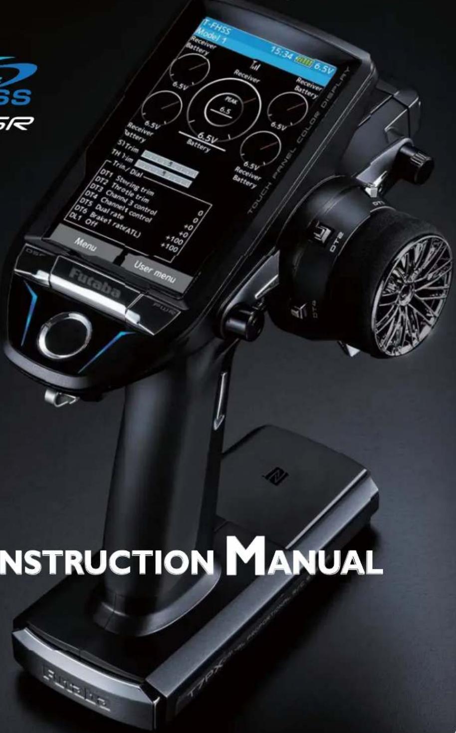
INSTRUCTION MANUAL
Futaba®
1M23N32604
CE
Digital Proportional R/C System
Thank you for purchasing a Futaba 7PX-2.4GHz system. Before use, read this manual carefully in order to use it safely. After reading this manual, store it in a safe place.
IN NORTH AMERICA
Please feel free to contact the Futaba Service Center for assistance with operation and programming. Please be sure to regularly visit the 7PX Frequently Asked Questions web site at https://www.futabausa.com/. This page includes extensive programming, use, set up and safety information on the 7PX radio system and is updated
regularly. Any technical updates or firmware updates and US manual corrections will be available on this web page. If you do not find the answers to your questions there, please see the end of our F.A.Q. area for information on contacting us via e-mail for the most rapid and convenient response.
Don't you have Internet access? Internet access is available at no charge at most public libraries, schools, and
other public resources. We find internet support to be a fabulous reference for many modelers as items can be printed and saved for future reference, and can be accessed at any hour of the day, night, weekend or holiday. If you do not wish to access the internet for information, however, don't worry. Our support teams are available Monday through Friday 8-5 Central time to assist you.
FOR SERVICE ONLY:
FUTABA Corporation of America 2681 Wall Triana Hwy Huntsville, AL 35824, U.S.A. Phone:1-256-461-9399 FAX:1-256-461-1059
https://www.futabausa.com/ E-mail: service@futabaUSA.com
OUTSIDE NORTH AMERICA
Please contact the Futaba importer in your region of the world to assist you with any questions, problems or service needs. Please recognize that all information in this manual, and all support availability, is based upon the systems sold in North America only. Products purchased elsewhere may vary. Always contact your region's support center for assistance.
Application, Export, and Modification
- This product may be used for models only. It is not intended for use in any application other than the control of models for hobby and recreational purposes.
- Exportation precautions:
(a) When this product is exported from the country of manufacture, its use is to be approved by the laws governing the country of destination for devices that emit radio frequencies. If this product is then re-exported to other countries, it may be subject to restrictions on such export. Prior approval of the appropriate government authorities may be required. If you have purchased this product from an exporter outside your country, and not the authorized Futaba distributor in your country, please contact the seller immediately to determine if such export regulations have been met.
(b) Use of this product with other than models may be restricted by Export and Trade Control Regulations, and an application for export approval must be submitted.
3. Modification, adjustment, and replacement of parts: Futaba is not responsible for unauthorized modification, adjustment, and replacement of parts on this product. Any such changes may void the warranty.
Compliance Information Statement (for U.S.A.)
This device complies with part 15 of the FCC Rules. Operation is subject to the following two conditions:
(1) This device may not cause harmful interference, and (2) This device must accept any interference received, including interference that may cause undesired operation.
(3)RF Radiation Exposure Statement (For T7PX)
This equipment complies with FCC radiation exposure limits set forth for an uncontrolled environment. This transmitter must not be co-located or operating in conjunction with any other antenna or transmitter.
RF Radiation Exposure Statement (For R334SBS)
This equipment complies with FCC radiation exposure limits set forth for an uncontrolled environment. This equipment should be installed and operated with minimum distance 20cm between the radiator & your body.
The responsible party for the compliance of this device is:
FUTABA Corporation of America
2681 Wall Triana Hwy Huntsville, AL 35824, U.S.A.
Phone:1-256-461-9399 FAX:1-256-461-1059
https://www.futabausa.com/
E-mail: service@futabaUSA.com
CAUTION:
To assure continued FCC compliance:
Any changes or modifications not expressly approved by the grantee of this device could void the user's authority to operate the equipment.
Declaration of Conformity (for EU)
Hereby, Futaba Corporation declares that the radio equipment type is in compliance with Directive 2014/53/EU.
The full text of the EU declaration of conformity is available at the following internet address:
http://www.rc.futaba.co.jp/english/dl/declarations.html
Battery Recycling (for U.S.A.)

The RBRC ™ SEAL on the (easily removable) nickel-cadmium battery and nickel-metal hydride battery contained in Futaba products indicates that Futaba Corporation is voluntarily participating in an industry program to collect and recycle these batteries at the end of their useful lives, when taken out of service within the United States. The RBRC ™ program provides a convenient alternative to placing used nickel-cadmium batteries and nickel-metalhydride batteries into the trash or municipal waste system, which is illegal in some areas.
You may contact your local recycling center for information on where to return the spent battery. Please call 1-800-8-BATTERY for information on NiCd/NiMH battery recycling in your area. Futaba Corporation's involvement in this program is part of its commitment to protecting our environment and conserving natural resources.
NOTE: Our instruction manuals encourage our customers to return spent batteries to a local recycling center in order to keep a healthy environment.
R TM is a trademark of the Rechargeable Battery Recycling Corporation.
For Your Safety As Well As That Of Others ....8
Explanation Of Symbols 8
Receiver Mode Precautions 8
Operation Precautions ......9
NiMH/NiCd/LiFe Battery Handling Precautions ....10
Storage And Disposal Precautions ....10
Other Precautions ....11
Before Using 12
Features 12
Set Contents ....14
Transmitter T7PX 15
Nomenclature....15
Battery Replacement Method....16
Low Battery Alarm ....16
When Using The Optional Battery ....17
When Charging For The Optional Battery ....18
Power & Display Switch 19
Display When Power Switch Is Turned On 20
Power Off Forgotten Alarm & Auto Power Off ....20
Trim/Dial Lock 20
Steering Wheel And Throttle Trigger Operation ....21
Digital Trim Operation 21
Mechanical ATL Adjustment 22
Wheel & Trigger Tension Adjustment 22
Trigger Slide Adjustment & Remove The High Point Spring .....23
Trigger brake lever replacement ....23
Changing Wheel Position And Modifying For Left-hand Use ..24
Exchange procedure to wheel adaptor 32 deg ....24
Installing the accessory APA steering wheel offset adapter .....24
Modifying for left-hand use ....27
Using the optional angle spacer ....29
Non-telemetry LED (telemetry OFF sign) 29
Handling the antenna and card slot and receiver ....30
About The Transmitter Antenna ....30
Receiver Terminology ....30
Receiver Installation ....30
Handling a microSD card (commercial product) ....31
Installation 32
Receiver And Servo Connections 32
Installation Safety Precautions ....33
Initial Set-Up 36
Preparations (Transmitter) 36
RF Output & Rx Type Check 36
Receiver system Change & How To Link ....37
Receivers Other Than T-FHSS 39
Response Mode/ SR Check 40
Trigger Ratio Check 42
Trims Initial Set-Up 42
Function Map 44
Menu Selection ....44
Display Menu Screen 44
Home Button Setting 45
Value Of Each Function And Changing The Set Value .....46
User Menu 47
Displaying And Editing The User Menu Screen ....47
Function List ....48
Function Map ....50
Functions ....52
Receiver (Telemetry function ON/OFF) 52
Channel Reverse ....53
Servo operation reversing
Sub Trim ....54
Servo center position fine adjustment
End Point ....55
End point adjustment
Fail-safe/ Battery Fail-safe ....58
Fail safe, battery fail safe function
Acceleration....60
Function which adjusts the movement characteristic from the throttle neutral position
Trigger 62
Throttle Servo Neutral Position/ Neutral Brake
Servo View 64
D/R, ATL 65
Steering D/R, Throttle ATL Rate
Trim Dial Select 66
Selection of functions operated by digital trim and dial
Switch Select 69
Selection of functions operated by switch
Idle-Up 72
Idle up at engine start
Channel Limiter 74
Limit the maximum operating amount of servo
Channel Setting ....75
Ability to assign steering or throttle to any channel
For Your Safety As Well As That Of Others
Before Using
Installation
Initial Set-Up
Function Map
Functions
Reference
Condition....76
Two kinds of data can be set in one model
Curve (EXP)....78
Steering operation curve/ Throttle curve/ Brake curve adjustment.
Steering curve 78
Throttle curve (Forward side) 80
Brake curve 83
Speed 84
Steering/ Throttle servo delay adjustment
Steering speed 84
Throttle speed 86
A.B.S....90
Pulse brake
Traction Control 95
Function to make traction progress by intermittently moving the throttle
Start 99
Throttle preset at start function
Engine Cut 101
Engine cut off by switch
Steering Mixing ....103
Twin servo steering system
Brake Mixing 106
Front and rear independent brake control for 1/5 GP car, etc.
Gyro Mixing 110
Use to set the Futaba car rate gyro
4WS Mixing 113
Special mixing used with Crawler and other 4WS type vehicles
Dual ESC ....116
Front ESC and rear ESC
CPS Mixing 118
Controls the Futaba CPS-1 channel power switch
Tank Mixing 120
This function is intended for vehicles such as tanks
Program Mixing (1, 2, 3, 4, 5) ......122
Programmable mixes between arbitrary channels
Tilt Mixing 125
Outboard engine
Timer....127
Up, Fuel down, lap, or lap navigation timer
Lap List ....134
Lap timer data (lap time, average lap time) check
S.BUS Servo 135
Special function, Futaba S.BUS/S.BUS2 servo parameter / SR mode setup
MC (ESC) Link ......140
Special function, Futaba ESC (MC960CR, MC851C, MC602C, MC402CR...etc.)
Roll Out Chart ....149
Gear Ratio Chart ....150
HOME Button Setting ....151
Telemetry System 152
Telemetry....153
Telemetry :Receiver Battery ....154
Telemetry :The Drive Battery Voltage .....155
Telemetry :RPM 156
Telemetry : Temperature ....157
Telemetry : The Drive Battery Electric Current .....158
Telemetry :GPS 160
Sensor List ....162
Sensor 164
Sensor Reload 165
Sensor Register 166
Change Slot 167
Speech guide interval and log data interval setting .....168
Telemetry meter display on home screen 168
Telemetry meter display settings 169
Model Select ....170
Model memory call
Model Copy 171
Model memory copy
Model Name ......173
Model memory name set/modify
Model Delete (Model saved on microSD card) .....174
Deletes model data saved on the microSD card
Data Reset 175
Model memory reset
Display....176
Information....178
Sound 180
Battery....181
Data And Time ....182
LED Setting 183
Calibration....184
Software Update ....186
Reference 187
Specifications....187
Warning Displays ....189
Optional Parts ....191
When requesting repair ....192
Use this product in a safe manner. Please observe the following safety precautions at all times.
Explanation Of Symbols
Please observe the following precautions to ensure safe use of this product at all times.
Meaning of Special Markings:
The parts of this manual indicated by the following marks require special attention from the standpoint of safety.
For safe use
| ⚠Danger | Procedures which may lead to dangerous conditions and cause death/serious injury if not carried out properly. |
| ⚠Warning | Procedures which may lead to a dangerous condition or cause death or serious injury to the user if not carried out properly, or procedures where the probability of superficial injury or physical damage is high. |
| ⚠Caution | Procedures where the possibility of serious injury to the user is small, but there is a danger of injury, or physical damage, if not carried out properly |
Symbols: : Prohibited : Mandatory

WARNING: Always keep electrical components away from small children.
Receiver Mode Precautions
Caution
! Be sure to use the T7PX receiver setting and the servo to be used under predetermined conditions. Under other conditions, the set will not operate, or the specified performance will not be displayed even if it operates. In addition, it may cause servo trouble. Futaba will not be responsible for problems caused by the use of other than genuine Futaba parts. Use the parts specified in the instruction manual and catalog.
| System | Response / SR node | Usable servos |
| T-FHSS SR | SR mode channel: ON | - SR mode of Futaba SR compatible servo.(See page 188 for current listings.) |
| SR mode channel: OFF | - Normal mode of Futaba SR compatible servo.- Futaba digital servo. | |
| T-FHSS | Digital servo | - Normal mode of Futaba SR compatible servo.- Futaba digital servo. |
| Analog servo | - Futaba all servo.(Normal mode of Futaba SR compatible servo.) | |
| S-FHSS | Digital servo | - Normal mode of Futaba SR compatible servo.- Futaba digital servo. |
| Analog servo | - Futaba all servo.(Normal mode of Futaba SR compatible servo.) | |
| FASST | Digital servo | - Normal mode of Futaba SR compatible servo.- Futaba digital servo. |
| Analog servo | - Futaba all servo.(Normal mode of Futaba SR compatible servo.) |
Receiver battery: Matched to the ratings of the receiver and connected servo (dry cell battery cannot be used).
In addition, the FSU Fail Safe Unit cannot be used because the system is different. Use the fail safe function of the transmitter. (Refer to page 58.)
Operation Precautions

Warning
Do not operate outdoors on rainy days, run through puddles of water or use when visibility is limited.
Should any type of moisture (water or snow) enter any component of the system, erratic operation and loss of control may occur.
Do not operate in the following places.
-Near other sites where other radio control activity may occur.
-Near people or roads.
-On any pond when passenger boats are present.
-Near high tension power lines or communication broadcasting antennas.
Interference could cause loss of control. Improper installation of your Radio Control System in your model could result in serious injury.
Do not operate this R/C system when you are tired, not feeling well or under the influence of alcohol or drugs.
Your judgment is impaired and could result in a dangerous situation that may cause serious injury to yourself as well as others.
Do not touch the engine, motor, speed control or any part of the model that will generate heat while the model is operating or immediately after its use.
These parts may be very hot and can cause serious burns.
Always perform an operating range check prior to use.
Problems with the radio control system as well as improper installation in a model could cause loss of control. (Simple range test method)
Have a friend hold the model, or clamp it down or place it where the wheels or prop cannot come in contact with any object. Walk away and check to see if the servos follow the movement of the controls on the transmitter. Should you notice any abnormal operation, do not operate the model. Also check to be sure the model memory matches the model in use.
! Turning on the power switches.
Always check the throttle trigger on the transmitter to be sure it is at the neutral position.
-
Turn on the transmitter power switch.
-
Turn on the receiver or speed control power switch.
Turning off the power switches
Always be sure the engine is not running or the motor is stopped.
- Turn off the receiver or speed control power switch.
- Then turn off the transmitter power switch.
If the power switches are turned off in the opposite order, the model may unexpectedly run out of control and cause a very dangerous situation.
When making adjustments to the model, do so with the engine not running or the motor disconnected.
You may unexpectedly lose control and create a dangerous situation.
Before running (cruising), check the fail safe function.
Check Method; Before starting the engine, check the fail safe function as follows:
1) Turn on the transmitter and receiver power switches.
2) Wait at least one minute, then turn off the transmitter power switch. (The transmitter automatically transfers the fail safe data to the receiver every minute.)
3) Check if the fail safe function moves the servos to the preset position when reception fails.
The fail safe function is a safety feature that minimizes set damage by moving the servos to a preset position when reception fails. However, if set to a dangerous position, it has the opposite effect. When the reverse function was used to change the operating direction of a servo, the fail safe function must be reset.
Setting example: Throttle idle or brake position
NiMH / NiCd / LiFe Battery Handling Precautions
(Only when NiMH/NiCd/LiFe batteries are used)
Warning
Never plug the charger into an outlet of other than the indicated voltage.
Plugging the charger into the wrong outlet could result in an explosion or fire.
Never insert or remove the charger while your hands are wet.
You may get an electric shock.
Do not use the T7PX transmitter's battery as the receiver's battery.
Since the transmitter's battery has an overload protection circuit, the output power will be shut down when the high current load is applied. This may result in runaway or fatal crash.
Always check to be sure your batteries have been charged prior to operating the model.
Should the battery go dead while the model is operating, loss of control will occur and create a very dangerous situation.
To recharge the transmitter battery, use the special charger made for this purpose.
Overcharging could cause the battery to overheat, leak or explode. This may lead to fire, burns, loss of sight and many other types of injuries.
Caution
Do not use commercial AA size NiCd and NiMH batteries.
Quick charging may cause the battery contacts to overheat and damage the battery holder.
When running (cruising), do not use the dry cell battery box at the transmitter.
The accessory dry cell battery box is for performance checks. Do not use it for other than performance checks. The dry cell batteries will be separated from the battery box contacts by shock and the power may be cut off. There is the danger of collision if the power is cut while running (cruising). The use of Futaba genuine NiMH or LiFe batteries is strongly recommended.
Do not short circuit the battery terminals.
A short circuit across the battery terminals may cause abnormal heating, fire and burns.
Do not drop the battery or expose it to strong shocks or vibrations.
The battery may short circuit and overheat; electrolyte may leak out and cause burns or chemical damage.
Do not connect the charger when the battery is not connected.
A load will be applied to the circuit and the transmitter may be damaged.
When the model is not being used, always remove or disconnect the battery.
Leaving the battery connected could create a dangerous situation if someone accidentally turns on the receiver power switch. Loss of control could occur.
Always keep the charger disconnected from the outlet while it is not in use.
Prevent accidents caused by abnormal heat generation etc.
Storage And Disposal Precautions
Warning
Do not leave the radio system or models within the reach of small children.
A small child may accidentally operate the system. This could cause a dangerous situation and injuries. NiCd batteries can be very dangerous when mishandled and cause chemical damage.
Do not throw NiMH/NiCd/LiFe batteries into a fire. Do not expose batteries to extreme heat. Also do not disassemble or modify a battery pack.
Overheating and breakage will cause the electrolyte to leak from the cells and cause skin burns, loss of sight, and other injuries.
When the system will not be used for any length of time, store the system with NiMH/NiCd batteries in a discharged state. Be sure to recharge the batteries prior to the next time the system is used.
If the batteries are repeatedly recharged in a slightly discharged state, the memory effect of the NiMH/NiCd battery may considerably reduce the capacity. A reduction in operating time will occur even when the batteries are charged for the recommended time. (After discharge to 1cell E.V.=1V)
When a LiFe battery pack will not be used for a long time, to prevent it from deteriorating we recommend that it be kept in about the half capacity state instead of fully charged. Also be careful that the battery does not enter the over-discharged state due to self-discharge.
Periodically (about every 3 months) charge the battery.

Warning
Do not store your R/C system in the following places.
- Where it is extremely hot or cold.
- Where the system will be exposed to direct sunlight.
- Where the humidity is high.
- Where vibration is prevalent.
- Where dust is prevalent.
- Where the system would be exposed to steam and condensation.
Storing your R/C system under adverse conditions could cause deformation and numerous problems with operation.
If the system will not be used for a long period of time, remove the batteries from the transmitter and model and store in a cool, dry place.
If the batteries are left in the transmitter, electrolyte may leak and damage the transmitter. This applies to the model also. Remove the batteries from it also to prevent damage.
The electrolyte in NiCd/NiMH batteries is a strong alkali. Should you get even the smallest amount of the electrolyte in your eyes, DO NOT RUB. Wash immediately with water, and seek medical attention at once. The electrolyte can cause blindness. If electrolyte comes in contact with your skin or clothes, wash with water immediately.
A used battery is a valuable resource. Insulate the battery terminals and dispose of the battery by taking it to a battery recycling center.
Other Precautions

Caution
Do not expose plastic parts to fuel, motor spray, waste oil or exhaust.
The fuel, motor spray, waste oil and exhaust will penetrate and damage the plastic.
Always use only genuine Futaba transmitters, receivers, servos, ESCs (electronic speed controls), NiMH/NiCd/LiFe batteries and other optional accessories.
Futaba will not be responsible for problems caused by the use of other than genuine Futaba parts. Use the parts specified in the instruction manual and catalog.
Features
-Full color touch screen LCD
T7PX has an HVGA 4.3 inch, full-color, backlit LCD touch screen. The screen is transflective which enables both indoor and outdoor visibility.
-T-FHSS SR(Super response) & telemetry T-FHSS
In addition to the T-FHSS telemetry system, we added a T-FHSS SR (Super response) system that increased processing speed to further improve response. (SR system does not support telemetry function)
-Updateable software
Software can be updated by microSD card. Model data can also be saved in a microSD card. In addition, telemetry log data can be saved.
-Model memory for 40 models
Model names can use up to 15 letters, numbers, and symbols, so that logical names may be used. A model memory with different setups can be created by using the model copy function.
-NFC communication
It is possible to update the T7PX itself in the future by NFC communication.
-Integral type dial switch
A switch with both dial (DL1) and push switch (PS6) functions.
-Brake mixing for large cars
Brake mixing of the front and rear wheels of 1/5GP and other large cars can be adjusted independently.
-Steering mixing
Smooth cornering is possible by the independent left and right steering servo setting.
-4WS mixing for crawlers and other 4WS type
This function can be used with crawlers and other 4-wheel steering type vehicles.
-Dual ESCs mixing for crawlers
ESC at the front and rear are controlled independently.
-Gyro mixing
The sensitivity of Futaba car rate gyros can be adjusted from the T7PX.
-Tank mixing
This function is intended for vehicles such as tanks.
-CPS mixing
LED lighting and flashing control using our CPS-1 channel power switch can be matched to steering and throttle operation by switch only.
-S.BUS servo
This is a special function that allows setting of the parameters of our S.BUS servo whose settings are changed by using PC Link software.
-MC-Link
This is a dedicated function which allows setting of the contents of the Link software which makes possible Futaba speed controller (ESC), MC960CR, MC950CR, MC850C, MC851C, MC602C, MC402CR, etc. variable frequency and other data changes by PC at the T7PX.
-Throttle speed
Sudden trigger operation on a slippery road surface will only cause the tires to spin and the model to not accelerate smoothly. By setting the throttle speed function, operation can be performed smoothly and easily. It also suppresses battery consumption.
-Steering speed
When you sense that the steering servo is too fast, etc., the servo operating speed (direction that suppresses the maximum speed) can be adjusted.
-Non-telemetry LED
When the telemetry function is OFF to confirm that the telemetry function is not operating.
-Dial select function
This function assigns functions to dials (digital trim, grip dial, knob). The step amount and operating direction can also be adjusted. Trim positioning at each model call is unnecessary because all the dials are digital.
-Switch select function
This function assigns functions to 5 switches. The operating direction can also be set.
-Wheel & Trigger position can be changed
The wheel position can be offset by using an accessory APA wheel position offset adapter. The wheel angle can also be adjusted.
The position of the throttle trigger can be moved forward and backward.
-Trigger brake lever replacement
The trigger brake lever is selected from a narrow nylon type and wide type
-Trim/dial lock functions
Lock functions which prohibit setting and operation by transmitter trim, and dials are provided.
-Left-handed support
The left and right installation direction of the wheel section can be reversed.
-Vibrator built into the grip
The vibrator can be operated at racing timer lap navigation, time-up, and low battery, telemetry alarm. It sets it on each function screen.
Set Contents
After opening the box, first check if the contents conform to the following. The contents depend on the set as shown below.
| Transmitter / Receiver | T7PX / R334SBS |
| Miscellaneous | Dry battery holder*Installed in transmitter.Wheel offset adapter (APA)Wheel adapter 32degLarge diameter steering wheel (54mm)Trigger brake lever (narrow type)Miniature screwdriverScreen protectorReceiver plugs x3Instruction manual |
- If any of the set contents are missing, or you have any questions, please contact your dealer.

Caution
! Be sure to use the T7PX receiver setting and the servo to be used under predetermined conditions.
Under other conditions, the set will not operate, or the specified performance will not be displayed even if it operates. In addition, it may cause servo trouble.
| System | Response / SR node | Usable servos |
| T-FHSS SR | SR mode channel: ON | - SR mode of Futaba SR compatible servo. |
| SR mode channel: OFF | - Normal mode of Futaba SR compatible servo.- Futaba digital servo. | |
| T-FHSS | Digital servo | -Normal mode of Futaba SR compatible servo.- Futaba digital servo. |
| Analog servo | - Futaba all servo.(Normal mode of Futaba SR compatible servo.) | |
| S-FHSS | Digital servo | - Normal mode of Futaba SR compatible servo.- Futaba digital servo. |
| Analog servo | - Futaba all servo.(Normal mode of Futaba SR compatible servo.) | |
| FASST | Digital servo | - Normal mode of Futaba SR compatible servo.- Futaba digital servo. |
| Analog servo | - Futaba all servo.(Normal mode of Futaba SR compatible servo.) |
Always use only genuine Futaba transmitters, receivers, servos, ESCs (electronic speed controls), NiMH/NiCd/LiFe batteries and other optional accessories.
Futaba will not be responsible for problems caused by the use of other than Futaba genuine parts. Use the parts specified in the instruction manual and catalog.
Receiver battery: Matched to the ratings of the receiver and connected servo (dry cell battery cannot be used).
In addition, the FSU Fail Safe Unit cannot be used because the system is different. Use the fail safe function of the transmitter.
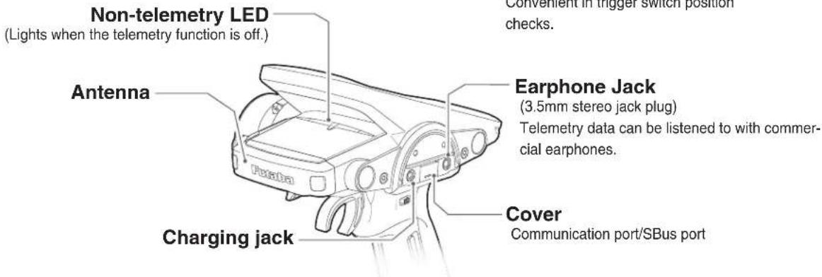
Nomenclature
*The switches, dial, and trimmers in the figure are shown in the initial setting position.
*Please be careful not to push the switch too strongly.


Battery Replacement Method
Load the four batteries in accordance with the polarity markings on the battery holder.
Battery Replacement Method
1 Remove the battery cover from the transmitter by sliding it in the direction of the arrow in the figure.
2 Remove the used batteries.
Caution
If you remove the dry cell battery box from the transmitter, replace it carefully with the wiring on the same side as before. Reinstalling the battery box in the opposite direction could cause the wires to be disconnected.
3 Load the new AA size batteries. Pay very close attention to the polarity markings and reinsert accordingly.
4 Slide the battery cover back onto the case.


Disposal of the Dry Cell Batteries:
The method to dispose of used dry cell batteries depends on the area in which you reside. Dispose of the batteries in accordance with the regulations for your area.
Caution
When running (cruising), do not use the dry cell battery box at the transmitter.
The accessory dry cell battery box is for performance checks. Do not use it for other than performance checks. The dry cell batteries will be separated from the battery box contacts by shock and the power may be cut off. There is the danger of collision if the power is cut while running (cruising). The use of Futaba genuine NiMH or LiFe batteries is strongly recommended.
Low Battery Alarm
If the transmitter battery voltage drops below the usable range, an audible alarm will sound and "Low battery" will be displayed (For details, see page 189). Since the usable range of NiMH batteries and LiFe batteries is different, the power supply used must be set by system setting (page 181). If the battery goes dead while running (cruising), since there is the danger of collision, immediately recover the vehicle (boat) and stop running (cruising).
Warning
When a low battery alarm is generated, cease operation immediately and retrieve the model. If the battery goes dead while in operation, you will lose control of the model.
When Using The Optional Battery
When using an optional rechargeable battery, replace the battery as described below.
-Always use the optional FT2F1700B, FT2F2100B or HT5F-1800B rechargeable battery.
-The type of power source used must be selected through the system setting (page 181).
-When the transmitter will not be used for a long time, remove the battery.
Battery Replacement Method
1 Refer to the previous description and remove the transmitter battery cover.
2 After removing the dry cell battery box from the transmitter, disconnect the connector.
Caution
If you remove the dry cell battery box from the transmitter, replace it carefully with the wiring on the same side as before. Reinstalling the battery box in the opposite direction could cause the wires to be disconnected.
3 Insert the connector of the new battery and load the new battery into the transmitter.
4 Finish by installing the battery cover.


Caution
When closing the battery cover, be careful that the battery cover does not pinch the battery lead wires.
Shorting of the battery lead wires may lead to fire and abnormal heating and cause burns or fire disaster.
Charging A NiMH Battery
(Example: When using the HT5F1800B with the special charger)
1 Plug the transmitter cord of the special charger into the charging jack on the rear of the transmitter.
2 Plug the charger into an AC outlet.
3 Check that the charging LED lights.
The charging time when charging the HT5F1800B battery with the optional special charger is approximately 15 hours. However, when the battery has not been used for some time, repeat charging 2 or 3 times to activate the battery.
Over current protection
The transmitter charging circuit is equipped with an over current protection circuit (1.0A). If the battery is charged with a quick charger for other than digital proportional R/C sets, it may not be fully charged.
Charging A LiFe Battery
(Example: When using the FT2F1700B/2100B the special charger)
1 Plug the transmitter cord of the special charger into the charging jack on the rear of the transmitter.
2 Plug the charger into an AC outlet.
3 Check that the charging LED lights red.
4 When charging is completed, the ccharging LED lights green. Disconnect the charge plug and disconnect the AC plug of the charger.

The charging time when charging the FT2F-2100BV2 battery with the optional special charger is approximately 3 hours.
With Balance Charger
(Example: When using the FT2F1700B/2100B with an optional charger)
1 Remove the battery cover.
2 Disconnect the battery from the T7PX.
3 Balance charging cannot be done through the transmitter. You must remove the LiFe battery to do this charge.
When the LiFe battery will not be used for a long time, to prevent it from deteriorating we recommend that it be kept in about the half capacity state instead of fully charged. Also be careful that battery does not enter the overdischarged state due to self-discharge. Periodically (about every months) charge the battery. In addition, always remove the battery from the model and store it in a dry, cool place (15°C to 25°C).
that the every 3
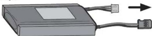
LiFe battery is removed from the transmitter.
Balance charging connector for LiFe battery charger. Follow the directions of the optional LiFe chargers in use.
Warning
Make sure not to peel off the battery film, or make any scratch by a cutter knife or the sharp edges of metal components.
Make sure not to soak or get the battery wet with water or seawater.
Make sure not to use a deformed or swollen battery.
There is a risk of explosion or fire, which is very dangerous.

Warning
Never plug it into an outlet having other than the indicated voltage.
Plugging the charger into the wrong outlet could result in an explosion or fire.
Do not insert and remove the charger when your hands are wet.
It may cause an electric shock.
Always use the special charger or a quick charger for digital proportional R/C sets to charge a digital proportional R/C set battery.
Overcharging a NiMH battery can result in burns, fire, injuries, or loss of sight due to overheating, breakage, or electrolyte leakage.

Caution
Do not plug the charger to the charging jack, if the battery is not connected to the transmitter.
The transmitter may be damaged.
When the charger is not in use, disconnect it from the AC outlet.
Do this to prevent accidents and to avoid overheating.
Power & Display Switch
The power switch and display switch are push switches.
When the power switch (PWR) is held down, operation starts by transmitting radio waves. When the display switch (DSP) is held down, the transmitter side data can be checked and set. When the power is turned off, if the power switch or display switch is held down, the power is turned off. If both switches are pressed simultaneously, the power is turned off quickly.
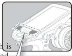
Power & Display Switch

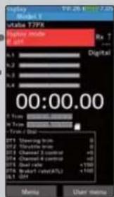
"Display mode RF off" is displayed
Radio waves are not being transmitted.
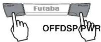
When the power is turned off, if the power switch or display switch is held down, the power is turned off. If both switches are pressed simultaneously, the power is turned off quickly.




When you do not run, turn OFFIt cannot operate.

*The figure above is partly processed for explanation, so it is different from the actual screen display.
Power Off Forgotten Alarm & Auto Power Off
At T7PX initialization, if steering wheel, throttle trigger, push switch, edit button, operation is not performed within 10 minutes, an audible alarm will sound and the mes "Warning: Auto power off" will appear (For details, see page 189.).
If steering wheel, throttle trigger, push switch, edit button or other operation is performed, the alarm is reset. Also turn off the power when the transmitter is not in use. If the alarm is not reset, the auto power off function will automatically turn off the power after 5 minutes. If you do not want to use this alarm and the auto power off function, they can be disabled by system setting (page 181).
Trim/Dial Lock
T7PX setup and operation by digital trim DT1, DT2, DT3, DT4, DT5 and DT6 and dials DL1 can be prohibited.
Setting
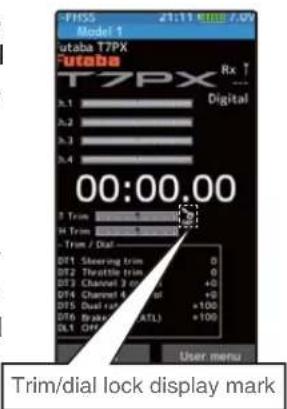
1 When the HOME button is pressed for about 1 second at the initial screen, a confirmation beep is generated and the trim/dial lock display mark appears on the screen.
Clearing
1 Edit button lock and trim/dial lock can be cleared in the initial screen state by the same method as the setting described above. (The trim/dial lock display disappears from the screen.)
Steering Wheel And Throttle Trigger Operation
(CH1: Steering wheel, CH2: Throttle trigger)
Steering Wheel Function: Turns the model right or left.
Throttle Trigger Function: Controls the speed of the model as well as the direction of travel - forward or reverse.
Throttle trigger function Steering wheel function


Digital Trim Operation
(Initial settings: DT1: Steering trim, DT2: Throttle trim, DT3: Channel 3, DT4: Channel 4, DT5: Steering D/R, DT6: ATL-Brake rate)
Operating by the trim: Push the trim lever to the left or right (up or down). The current position is displayed on the LCD screen.
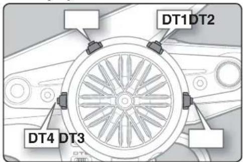

• Each step is indicated by a tone.
- When the trim exceeds the maximum trim adjustment range, the beep will change and the servo will not move any farther.
- When the steering wheel is neutral, adjust the steering trim so that the car goes straight without curving left and right.
- Adjust the throttle trim so that the car stops when the throttle trigger is in neutral so that the brake will not be applied when the throttle trigger is released during operation.
- Steering D/R: The steering left and right servo travels are adjusted simultaneously.
- ATL: Decreases the set value when the braking effect is strong and increases the set value when the braking effect is weak.
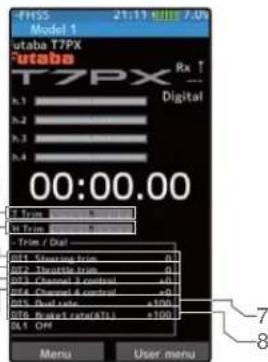
Steering And Throttle Trim Operation
• 1/3-DT1 (Steering trim display)
• 2/4-DT2 (Throttle trim display)
• 5-DT3 (Channel. 3 display)
• 6-DT4 (Channel. 4 display)
• 7-DT5 (Steering D/R display)
• 8-DT5 (ATL display)

With the center trim feature, trim adjustments have no effect on the maximum servo travel. This prevents the linkages from binding when adjustments are made.
Mechanical ATL Adjustment
Make this adjustment when you want to decrease the stroke of the brake (back) side of the throttle trigger for operation feel.
Adjustment
1 Using a 1.5mm hex wrench, adjust the trigger brake (reverse) stroke. (The screw moves the throttle trigger stopper.)
- When the screw is turned clockwise, the stroke becomes narrower. Adjust the stroke while watching the screw.

Note:
Once you have changed the mechanical stroke on the brake side, be sure to adjust the scale of the throttle channel accordingly by using the "Calibration Function" (page 184).
Due to this change, you also need to adjust in most cases the travel of the throttle servo by using "Data Setting."
Wheel & Trigger Tension Adjustment
Make this adjustment when you want to change the wheel or trigger spring's tension.
Adjustment
1 Using a 1.5mm hex wrench, adjust the wheel spring tension by turning the screw inside the adjusting hole.
- The spring is set to the weakest tension at the factory.
- When the adjusting screw is turned clockwise, the spring tension increases.
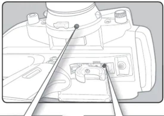
Wheel tension adjusting screw
Trigger tension
adjusting screw
Note:
The adjustment range is up to 7 to 8 turns from the fully tightened (strongest) position. If turned farther than this, the adjusting screw may fall out.
Trigger Slide Adjustment & Remove The High Point Spring
The throttle trigger position can be moved forward and backward.
Adjustment
1 Using a 2.0mm hex wrench, loosen the trigger slide mounting screw by turning it slightly counterclockwise.
Always loosen this screw.
Note:
If the trigger slide screw is much, the screw may fall out.
2 Adjust the trigger slide position within the marked range.
The high point spring can be removed by moving to the farthest from the grip. When the high point spring is removed, perform throttle side correction by calibration function (page 184).
3 Retighten the mounting screw loosened at step 1 and fasten the trigger slide.

Trigger brake lever replacement
The trigger brake lever is available in a narrow nylon type and wide type. (Narrow type is installed at the factory.)
*When the brake lever is changed, perform throttle side correction by adjuster function (page 184).
Brake lever replacement
Obtain a 1.5mm hex wrench. Remove the battery from the transmitter.
1 Hold the trigger, remove the brake lever mounting screw using the 1.5mm hex wrench, and remove the brake lever.
2 Using the 1.5mm hex wrench install the wide type brake lever with the brake lever mounting screw.

Changing Wheel Position And Modifying For Left-hand Use
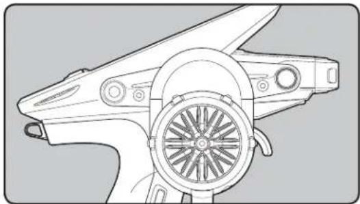
Changing the wheel position
The wheel position can be offset by using the accessory APA wheel position offset adapter. (See page 25 for the modification method.)

Modifying for left-hand use
The wheel section left and right installation direction can be reversed. (See page 25 for the modification method.)
Angle can be adjusted
The angle can be finely adjusted by adjusting the steering wheel unit installation. (See the modification method on the next page for the adjustment details.)
The operating angle of the wheel can be adjusted
The operating angle of the wheel can be changed from 34 deg to 32 deg by installing the 32 deg wheel adjuster. (See "Exchange procedure to wheel adaptor 32 deg" below for the replacement procedure.
If you install the 32 deg wheel adapter, be sure to adjust the scale of the steering channel accordingly by using the "Calibration Function" (page 184).
Exchange procedure to wheel adaptor 32 deg and large diameter wheel
- Obtain 2.5mm hex wrench./ Remove the battery.
1 Hold the wheel and remove the screw. (Using a 2.5 mm hex wrench.)
2 Pull off the wheel and wheel adapter.
3 Install the standard or large diameter steering wheel and the 32 degree wheel adapter using the screw. (Using a 2.5 mm hex wrench.)


Installing the accessory APA steering wheel offset adapter
- Obtain 2.5mm hex wrench./ Remove the battery.
- The length of the screws used at each part differs. When reassembling the steering wheel unit, always use the specified screws.
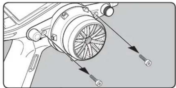
1 Remove the 2 steering wheel unit mounting screws (3.0x12mm cap screw).
(Using a 2.5 mm hex wrench.)
Remove the 2 mounting screws completely from the transmitter body.
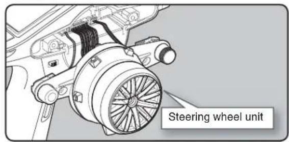
2 Gently remove the steering unit, without pulling excessively on the wiring.
- Since there are locking tabs on the top and bottom of the steering unit, please do not pull straight out forcefully.
- Please slowly remove in the order of 1→3 in the right figure.
- Remove the steering unit slowly so that the internal wiring is not pulled unreasonably.

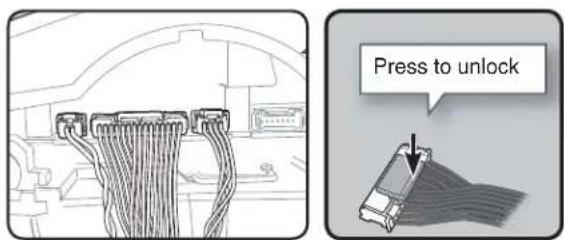
3 Remove the 3 connectors from the PC board.
Press the upper side of the connector to release the lock and remove it from the PC board. (The 3 connectors each have the same lock type although they are different in size.)
4 Using a Phillips screwdriver, remove the 4 screws (2.6x15mm tapping screw) mounting the wheel unit and switch unit.


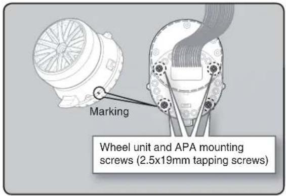
5 Pass the wiring from the steering wheel unit through the hole in the APA as shown in the figure. Using a Phillips screwdriver fasten the wheel unit and APA at the desired angle using the 2.6x19 tapping screws. - Be careful that the screw length is correct. Be careful that the wiring does not get pinched. - The 2.6x19 tapping screws in the accessory bag - The angle can be adjusted, but check the marking point on the wheel unit and install the screws. - Screws can be installed at 4 places, but installation at 4 places may be impossible due to the wheel unit mounting angle.

6 Using a Phillips screwdriver fasten the switch unit and APA. Use the 2.6x10mm tapping screws in the accessories bag. Next, install the APA rear cover. Be careful that the length of the screws is correct.
- The 2.6x10 tapping screws in the accessory bag.


7 Install the assembled steering wheel unit to the transmitter body.
- From left to right, the order is 2 pin connector (PS3), 15 pin connector (wheel unit), 4 pin connector (DL1 / PS6).
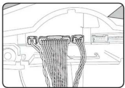
8 Install the assembled steering wheel unit and APA to the transmitter using the screw (3.0x12mm cap screw) supplied.
(Using a 2.5 mm hex wrench.)
- Install slowly so that the wiring is not pinched.
- Installation is easy if inserted in 1→2 order.


Modifying for left-hand use
- Obtain 2.5mm hex wrench.
- Refer to 1-2 (page 25) of the APA for the wheel position change installation method.
1 Slowly pull out the PS5 switch cap and mounting plate in the arrow direction.
- Be careful that the switch body does not get caught and damaged.
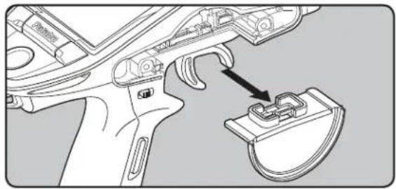
2 Using a 2.5mm hex wrench, remove the mounting screws (3.0x1.2mm cap) of the opposite side charge unit.
- Remove the 2 mounting screws completely from the transmitter body.

3 Being careful that the wiring is not too tight slowly remove the charging unit. Remove the connector from the PC board.
- Press the upper side of the connector to release the lock and remove it from the PC board (See page 25).


4 Install the charging unit to the connector on the opposite side of the transmitter body. • Install slowly so that the wiring is not pinched.
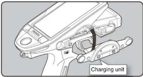

5 Using a 2.5 mm hex wrench, attach the charging unit and the transmitter body with mounting screws.

6 Install the PS5 switch cap and mounting plate removed at step 1 at the opposite side of the transmitter body.
- Be careful that the switch body does not get caught and damaged.

7 Insert the connector of the steering unit into the board on the opposite side of the transmitter and attach it to the main unit.
- Install slowly so that the wiring does not get pinched. - Installation is easy when inserted in 1→2 order. (Figure at the right)


8 Install the assembled steering wheel unit to the transmitter using the screw (3.0x12mm cap screw) supplied. (Using a 2.5 mm hex wrench.)
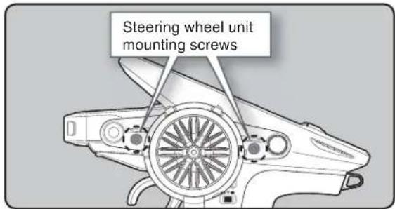
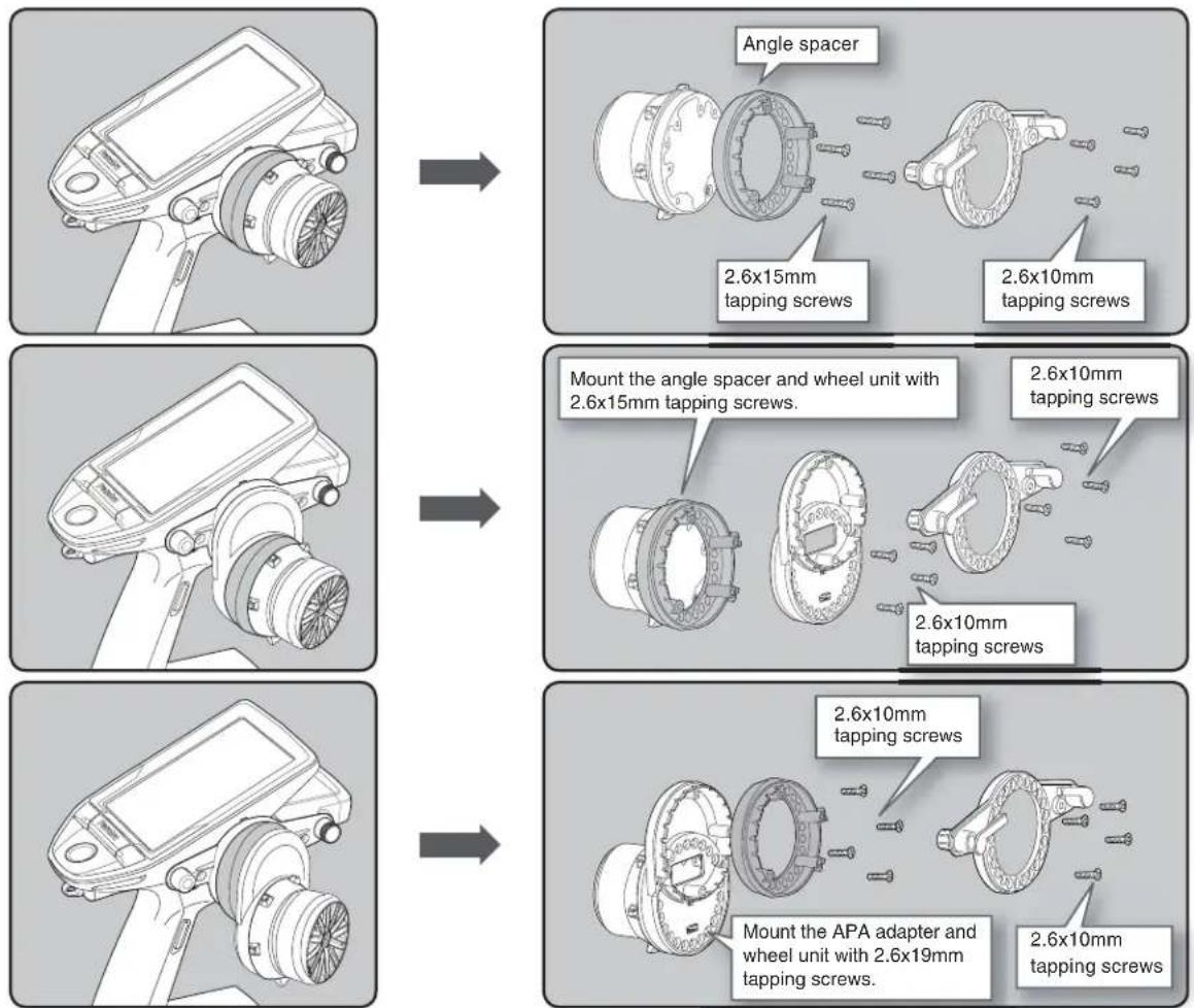
The wheel mounting angle can be changed by using the optional angle spacer.
Three 2.6x10mm tapping screws are supplied with the angle spacer.
When using and not using the APA, refer to the following installation.
Obtain a Phillips screwdriver. Be careful of the length of the screws used.
Actually, since there is wiring, the wheel is assembled by passing the screws through each part.
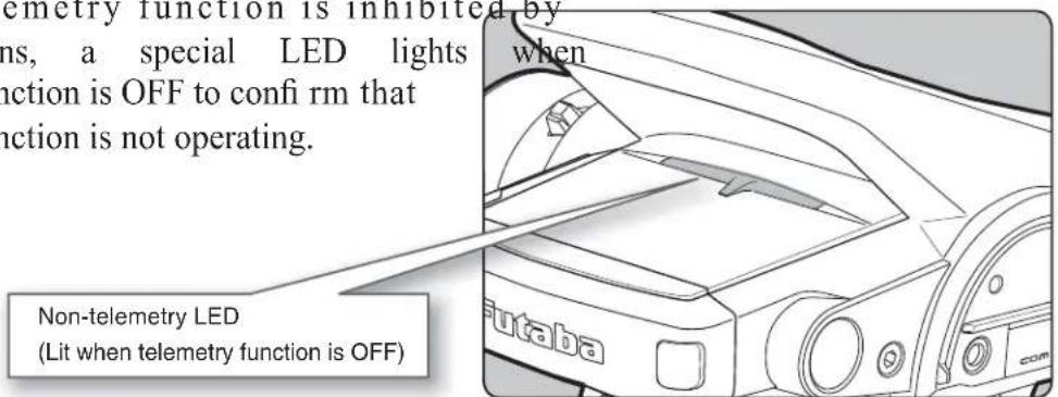
Non-telemetry LED (telemetry OFF sign)
When the telemetry function is inhibited by race regulations, a special LED lights the telemetry function is OFF to confirm that the telemetry function is not operating.
Handling the antenna and card slot and receiver
About The Transmitter Antenna
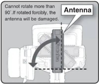
Antenna Moving Range
If the antenna is set to the 45° and 90° vertical position, the range of the radio waves may be greater than in the horizontal position. (Different depending on the conditions)

Caution
Please do not grasp the transmitter's antenna while driving.
Doing so may degrade the quality of the RF transmission to the model.
The antenna position can be changed in the direction as shown in figure. However, please do not apply unnecessary force or shock.
The internal cable may be damaged; thus transmitting distance decreases and it may cause malfunction.
There might be a small glitch when the antenna of the transmitter is brought close to servos, ESCs or other peripheral devices.
This is not an issue but please keep this symptom in mind, especially when setting-up.
Receiver Terminology
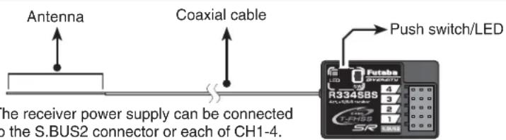
Connectors
4 :CH4 servo(CH4)
3 :CH3 servo(CH3)
2 : Throttle servo(CH2)
1 :Steering servo(CH1)
S.BUS2:Power /S.BUS2 connector
Receiver Installation
Install the R334SBS receiver on the car as follows:
The operating range may become shorter, depending on where the receiver and the antenna are mounted.
WARNING
Do not cut or bundle the receiver antenna wire.
Do not bend the coaxial cable. It causes damage.
Install the antenna in the higher place as shown in the figure.
- Put the antenna in the antenna tube to protect it.
- Keep the antenna as far away from the motor, ESC and other noise sources as you possibly can.
- Wrap the receiver with something soft, such as foam rubber, to avoid vibration. If there is a chance of getting wet, put the receiver in a waterproof bag or balloon.
It is a receiver of diversity type of external antenna and case internal antenna. Do not place wiring or other objects on the plate. The receiving range may be affected.


Caution
① Always use R334SBS under the following conditions:
Battery :Power requirement Rated voltage 3.8 to 7.4V (dry cell battery cannot be used)
Matched to the ratings of the receiver and connected servo.
- Transmitter's receiver system > T-FHSS SR-SR mode channel (ON): SR mode of Futaba SR compatible servo.
- Transmitter's receiver system > T-FHSS SR-SR mode channel (OFF) Normal mode of Futaba SR compatible servo.
:Futaba digital servo.
- Transmitter's receiver system > T-FHSS/S-FHSS/FASST
Transmitter's response type: Digital servo :Futaba digital servo
Transmitter's response type: Analog servo :Futaba all servo (Normal mode of Futaba SR compatible servo.)
Under other conditions, the set will not operate, or the specified performance will not be displayed even if it operates. In addition, it may cause trouble with servos and other equipment. Futaba will not be responsible for damage, etc. caused by combination with the products of other companies.
Note: However, digital servos (including BLS Series brushless servo) can only be used in the "Digital servo type".
Handling a microSD card (commercial product)
T7PX model data and telemetry log data can be saved by using a commercial microSD card. When T7PX software updates are released, the microSD card can also be used to make the update.

Insert the card with the metal terminals side at the bottom.
Remove the card by pushing it in and then pulling it out.
Install and remove the card by pushing it in until you hear a click.
(Commercial product)
SD standard and SDHC standard microSD cards
SD/SDHC format. Maximum size 32MB. SDXC format is not supported. (Some models may not be operated by card.)
*The data in the memory card cannot be guaranteed regardless of the contents and cause of trouble or damage. Always back-up the valuable data in the memory card.

Caution
①Always insert and remove the microSD card in the state in which the transmitter power is off.
If the microSD card is removed while being accessed (read or write), the card itself and the data may be destroyed.
Do not install and remove the microSD card with the microSD card slot facing your face.
If you remove your fingers quickly, the microSD card may fly out and strike your face and is dangerous.
Since the microSD card is a precision device, do not subject it to unreasonable force or shock.
-When a microSD card is installed in the T7P mitter, a folder called "Futaba" is created. Folders called "LOG" and "MODEL" are created in this folder. "MODEL" folder stores the model data and LOG" folder stores the telemetry log data. When "Save screen" is
![graph LR A["The FUTABA"] --> B["LOG"] A --> C["MODEL"] A --> D["PICTURE"]](/content/2026/07/1443791/images/52a946b3b3c4d3d618f0cc7e3f0e3256fb224f5b502fc4a45a048627931037ed.jpg)
set at the push switch by switch select (page 69), an image of the screen to be displayed on the T7PX is saved by that switch. The saved image is stored in a folder call "PICTURE". A "PICTURE" folder is not created until "Save screen" switch is set and the Screen Capture.
-The telemetry log data recorded on the microSD card can be converted to CSV format by the telemetry log converter released on our home page. When copying or moving a log file, always select both .FLI and .FLD file.
Receiver And Servo Connections
Connect the receiver and servos as shown below. Connect and install the receiver and servos in accordance with "Installation Safety Precautions" on the next page.
The figure shown below is an example. The method of connecting the motor controller to the motor and battery depends on the motor controller used. Purchase the motor controller and servos separately. The receiver also depends on the set.
When using the DSC cord with a gasoline engine car, connect the optional double extension cord to B/C of the receiver and the DSC cord and receiver switch to the opposite side connector.
Installation When An Electronic Speed Control Is Used
![graph TD A["Motor"] --> B["Battery"] B --> C["Switch"] C --> D["ENC"] D --> E["Receiver"] E --> F["Steering servo"] F --> G["CH1"] G --> H["CH2"] H --> I["MC"]](/content/2026/07/1443791/images/1971d83de4c42399e69f958ffa660971be3c61d557b289d4a6e748896a10daab.jpg)
Installation For Gas Powered Models
![graph TD A["Receiver"] -->|CH1| B["To Battery"] A -->|B/C| C["Switch"] A -->|CH3| D["Ch4 servo"] A -->|CH2| E["Steering servo"] A -->|CH4| F["Ch3 servo"]](/content/2026/07/1443791/images/0c524085e21c7b77e65429d373895fddcdfb934f191691d8ff5a32b44a36ec5c.jpg)
Installation Safety Precautions
Warning
Receiver (receiver antenna)
Do not cut or bundle the receiver antenna wire.
Do not bundle the receiver antenna wire together with the motor controller lead wire.
Keep the receiver antenna wire at least 1cm away from motor, battery, and other wiring carrying heavy current.
Do not use a metal receiver antenna holder on a plate made of metal, carbon, or other conductive material.
Install the receiver antenna holder as closely as possible to the receiver.
If the antenna wire is cut, bundled, or routed near a noise source, the receiving sensitivity will drop, the running (cruising) range will decrease, and you may lose control of the model.
*Noise is transmitted through metal, carbon, and other conductive material, so keep the receiver antenna wire away from such parts.

Install the receiver as far away as possible from the battery, motor controller, motor, silicon cord and other noise sources. Keep it away from the antenna wire, in particular.
Since the antenna of built-in antenna receivers is installed under this, do not place wiring or other objects on it.
Receiver Vibration-proofing / Waterproofing
(Car)
Vibration-proof the receiver by wrapping it in foam rubber or other vibration-absorbing material and mount it with thick double-sided tape.
When using the receiver holder supplied with the model kit, mount the holder to the chassis through a rubber grommet.
(Boat)
Vibration-proof the receiver by wrapping it in foam rubber or other vibration-absorbing material. Also waterproof the receiver by cruising it in a plastic bag.
If the receiver is exposed to strong vibration and shock, it will operate erroneously due to the invasion of water drops and you may lose control of the model.

When using the receiver holder supplied with the kit, install the receiver through a rubber grommet.
Foam rubber, etc.

Wrap the receiver in foam rubber or other vibration-absorbing material. Do not use hard material. Hard material does not have a vibration-proofing effect.

When mounting the receiver with double-sided do not use a stiff tape. Stiff tape does not have a vibration-proofing effect.
tape,

Warning
Connector Connections
- Be sure the receiver, servo, battery and connectors are fully and firmly connected.
If vibration from the model causes a connector to work loose while the model is in operation, you may lose control.
Servo Installation
When you install the servos, always use the rubber grommets provided in servo hardware bags. Mount the servos so they do not directly come in contact with the mount.
If the servo case comes in direct contact with the mount, vibration will be directly transmitted to the servo. If this condition continues for a long time, the servo may be damaged and control will be lost.

Servo Throw
① Operate each servo over its full stroke and be sure the linkage does not bind or is loose.
The continuous application of unreasonable force to a servo may cause damage and excessive battery drain.

Decide the EPA value at the contact point.
Adjust the steering servo so that unreasonable force is not applied to the servo by the chassis at maximum servo travel.

Adjust the throttle servo so that unreasonable force is not applied when the engine carburetor is fully open, fully closed, and the brakes are applied fully. If the brakes overheat while running, their ability to function properly decreases. Before running, adjust the suitable maximum servo travel so that unreasonable force is not applied even when the servo travel is increased while running.

Warning
Electronic Speed Cont
Install the heat sinks where they will not come in contact with aluminum, carbon fiber or other parts that conduct electricity.
If the FET Amp (Electronic speed control) heat sinks touch other materials that conduct electricity a short circuit could occur. This could result in loss of control and damage to the system.
Motor Noise Suppression
① Always install capacitors to suppress noise when electric motors are used.
If capacitors are not properly installed you could experience erratic operation and reduced range as well as loss of control.
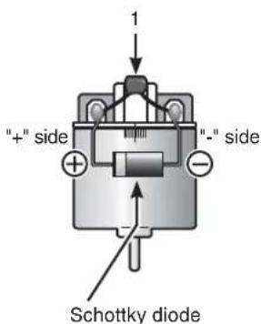
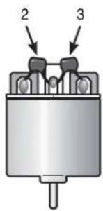
Motors with no suppressor capacitors, or inadequate suppression, may cause the receiver to malfunction. Always solder the capacitors supplied to your motor.
The Schottky diode improves the efficiency of the speed control / motor combination and provides extra protection to the brake FETs. The white ring must always face the positive side.
Other Noise Suppression Methods
① Be sure there are no metal parts in your model which under vibration can come in contact with other metal parts. Metal to metal contacts under vibration will emit a high frequency noise that will affect the receiver's performance. You could experience erratic operation and reduced range as well as loss of control.
Preparations (Transmitter)
(Display when power switch turned on)
When the power switch is turned on, the currently selected model number is displayed. Check if this number is the model number you want to set-up. To change the model number, use the Model Select function. (page 170)
Turn on the transmitter power.

Before setting up each function of the transmitter, check and set the following items.
RF Output & Rx Type Check
Check if the receiver system is set to the type of receiver used.
*When the "PWR" side power switch is set to ON and radio waves is displayed
are output normally, "T-FHSS SR ", "T-FHSS ", "S-FHSS", or "FASST" is displayed. If not displayed, there is probably an abnor trouble so contact a Futaba Service Center.
When a screen is displayed at the "DSP" side, "Display" is displayed.
*Since the R334SBS receiver supplied with the T7PX set uses the T-FHSS SR (Super response) or telemetry function T-FHSS T7PX receiver setup must be set to T-FHSS SR or T-FHSS.
The R2104GF and other S-FHSS and FASST system receivers, as well as the R304SB T-FHSS system receiver can be used T7PX transmitter. However, only R614FS/FS/FF-E and R604FS/FS-E"C2" type receivers can be used with the FASST system.
The R603FS/FF"C1" type cannot be used.

For "T-FHSS SR" system
Receiver system Change & How To Link
First set up the receiver. Setting changes are immediately reflected. Next, the tran and receiver are linked and the receiver memorizes the transmitter ID number so that sig - nals from other transmitters will not be received.
In addition, with the T-FHSS telemetry system, the transmitter simultaneously memorizes the receiver ID numbers so that data from other receivers will not be received.
The method of setting up the receiver system and the method of linking the transmitter and receiver are described. Refer to the figure at the right for the edit buttons used.
1 Set the transmitter "PWR" side power switch to ON. From the Home screen, press the HOME button or tapped [Menu] on the touch panel. Next, select [Receiver] at the Linkage menu and access the setup screen shown below by tapping the screen.
![graph LR A["Menu"] --> B["Linkage"] B --> C["Connection"] A --> D["User menu"] D --> E["Home"] subgraph Menu F["FHSS 21:11 KUI$7.0V<br>Model 1<br>Futaba T7PX Rx ↑<br>Digital<br>00:00.00<br>3.1 Trim<br>04 Trim / Dual<br>01 Steering trim 0<br>02 Flatlet trim 0<br>03 Channel 3 control +0<br>04 Channel…](/content/2026/07/1443791/images/84a3f4a122befff26f9d3207280888ad6438242ad38c1492fb3e5debf0438dcf.jpg)
2 In "Receiver", select and tap the system to be set from T-FHSS SR, T-FHSS, S-FHSS, FASST. The confirmation screen will be displayed. To execute, tap [Yes] to hear an electronic sound and finish setting. To cancel, select [No] and touch it. If you change the system, be sure to link it with the receiver and turn the power on again.
![graph TD A["FHS5 Model 1"] --> B{Are you sure?} B -->|Yes| C["Changing System Please wait."] B -->|No| D["S-FHSS/FASST T-FHSS T-FHSS SR"] E["Receiver ID"] --> F["Link"] F --> G["Digital servo"] G --> H["Telemetry ON"] I["2AGle SAHSS"] --> J["Response: Digital servo"] K["TFASST"] --> L["Response: Dig…](/content/2026/07/1443791/images/cce2b8d2d8259e032f6f352fa7bd5608f1b0fc346573e0924a101b3e724c6e37.jpg)

* After set up this far is complete, when using a FASST system (R614FS/FF/FF-E) or S-FHSS system (R2104GF, R204GF-E, etc.) receiver, go to "Receiver Other Than T-FHSS" on page 39. When using a T-FHSS SR receiver (R334SBS) and T-FHSS receiver (R304SB, etc.) go to next step 3.
3 Bring the transmitter and receiver within 50cm of each other (antennas do not touch) and turn on the receiver power.
4 Touch [Link] on the transmitter T7PX screen, you will hear a chime sound and T7PX will enter the link mode for 20 seconds. During the 20 second link mode, push the receiver side push switch for about 2 seconds or more.
![graph TD A["Receiver"] --> B["Link with receiver"] B --> C["Now linking... Remain 18 seconds"] C --> D["Close"] D --> E["R334SBS"] E --> F["LED SW"] E --> G["LED Switch"]](/content/2026/07/1443791/images/9830d03be9dba17f4dfdf246f85a13e1b127af81c2ca1b5de86f578467d7c410.jpg)
5 During the 20 seconds link mode, press the receiver for at least 2 seconds. The LED blinks red and then changes to a greenish red → green steady light. When the T7PX makes a beeping sound and the message "Link with receiver" appears on the screen, release the receiver push switch. This ends reading of mutual ID and displays the memorized receiver ID number on the T7PX screen. Power cycle the receiver. If the "Receiver not found" error screen is displayed, linking failed. Check the set contents and repeat the linking operation.
![graph TD A["Link established"] --> B["Link with receiver"] B --> C["Link established. Please restart the receiver. Remain 17 seconds"] C --> D["Close"] D --> E["The link is completed. Repeat the link run operation"] F["T-FHSS SR"] --> G["Receiver ID: 171702221 Link"] G --> H["Response: Digital servo…](/content/2026/07/1443791/images/3b83c16dbdb224c3dd669b74fc2bd32945f44762a6ea9f0ba619e716d000c115.jpg)

The T7PX and T-FHSS SR receiver (R334SBS)/ T-FHSS receiver (R304SB, etc.) memorize the IDs linked last at each model memory. Since only one receiver ID is memorized at each model memory, multiple T-FHSS SR/ T-FHSS receivers cannot be used with the same model memory. When a receiver at the same model memory is changed, re-linking is necessary even if the receiver is already linked with the transmitter.
When using multiple T-FHSS SR/ T-FHSS receivers, link each receiver with each T7PX model memory.
However, one receiver can be linked with multiple model memories. The telemetry function communication status can be checked at the T7PX home screen.
Receivers Other Than T-FHSS
1 Bring the transmitter and the receiver close to each other, within 20 inches (half meter).
2 Turn on the power switch (PWR). On the display (DSP) side, you can not link.
3 Turn on the receiver.
4 Push the push switch of the receiver.
When the link is complete, the LED in the receiver changes to solid green. Actually check the operation of the servo.

Precaution:
If there are many Futaba 2.4GHz systems turned on in close proximity to your receiver might not link to your transmitter. In this case, even if the receiver's LED stays solid green, unfortunately the receiver might have established a link to one of other transmitters. This is very dangerous if you do not notice this situation. In order to avoid the problem, we strongly recommend you to double-check whether your receiver is really under control by your transmitter by giving the stick input and then checking the servo response.
*Please refer to the table below for LED status vs receiver's condition.
LED status vs receiver's condition:
| No signal reception Red : On | |
| Receiving signals Green: On | |
| Receiving signals, but ID is unmatched. Green: Blink | 1 (T-FHSS ,Red : On) |
| Unrecoverable failure (EEPROM,etc.) LED: Red and Green turn on | alternately |
*1: LED could be change to red during intermittently during data processing.

Warning
After the linking is done, please cycle receiver power and check if the receiver to be linked is really under the control of your transmitter.
Do not perform the linking procedure with motor's main wire connected or the engine operating as it may result in serious injury.
Make sure that the response mode or SR mode setting matches the servo or other equipment to be used.

If the setting is incorrect, change it by the following method.
How to set the response / SR mode
1 From the Home screen, press the HOME button or tapped [Menu] on the touch panel. Next, select [Receiver] at the Linkage menu and access the setup screen shown below by tapping the screen.
![graph LR A["Menu"] --> B["Linkage menu"] B --> C["Connector"] C --> D["Display"]](/content/2026/07/1443791/images/7ad06c1c9bb586c779c5a4b42addffd221513e25736cdc3d103e9253df916e46.jpg)
2 For the T-FHSS / S-FHSS / FASST system, tapped [Digital Servo] or [Analog Servo] in the receiver setting and make changes. The display changes when mode is changed.
When the power of the receiver is turned on, be sure to turn the power off and then on again.
![graph LR A["Receiver"] --> B["From an analog servo to a digital servo"] A --> C["From a digital servo to an analog servo"] B --> D["Changes to a digital servo"] C --> E["Changes to an analog servo"]](/content/2026/07/1443791/images/8214b95d6d0858f88bd0e95d3fa7d544715ea4d030f9e861c410905e6099d017.jpg)
In the case of T-FHSS SR, "SR mode" which has greatly improved response compared to the conventional T-FHSS can be used. Tap and change (ON)/ (OFF) of each channel of SR mode. The display changes when you change it. Be sure to turn off the power of the receiver before operation check.
In SR mode, ON/OFF can be set for each channel. When using normal servo or ESC, set the SR mode of the connected channel to (OFF).
Note: In SR mode ON, normal servo and ESC will not operate. Please set our S.BUS servo corresponding to SR mode to SR mode on S.BUS servo menu on page 135 and use it. Also, in case of SR mode OFF, the servo set to SR mode can not be used, so set the servo to normal mode by S. BUS servo menu. If using wrong combination, servo and other equipment will fail, so please be careful.
![graph TD A["To change SR mode setting, tapped [Yes"], and if you want to cancel, tapped["No"].] --> B{Are you sure?} B -->|Yes| C["When switching to SR mode, be sure to change the operation mode of servo to SR mode."] B -->|No| D{Warning: SR mode Please restart the receiver. Please operate the wheel…](/content/2026/07/1443791/images/873232921adf6fb3a3d217a4bf055fb4b70f6885edc69fd9684668179bdf947f.jpg)
Servo conforming to the setting of response / SR mode
| System | Response / SR node Usable | servos |
| T-FHSS SR | SR mode channel: ON | -SR mode of Futaba SR compatible servo. |
| SR mode channel: OFF | - Normal mode of Futaba SR compatible servo.- Futaba digital servo. | |
| T-FHSS | Digital servo | - Normal mode of Futaba SR compatible servo.- Futaba digital servo. |
| Analog servo | - Futaba all servo.(Normal mode of Futaba SR compatible servo.) | |
| S-FHSS | Digital servo | - Normal mode of Futaba SR compatible servo.- Futaba digital servo. |
| Analog servo | - Futaba all servo.(Normal mode of Futaba SR compatible servo.) | |
| FASST | Digital servo | - Normal mode of Futaba SR compatible servo.- Futaba digital servo. |
| Analog servo | - Futaba all servo.(Normal mode of Futaba SR compatible servo.) |
! Be sure to use the T7PX receiver setting and the servo to be used under predetermined conditions. Under other conditions, the set will not operate, or the specified performance will not be displayed even if it operates. In addition, it may cause servo trouble. Futaba will not be responsible for problems caused by the use of other than Futaba genuine parts. Use the parts specified in the instruction manual and catalog.
Trigger Ratio Check
-The throttle servo travel can be set to 50:50, 70:30 or 100:0 for throttle trigger operation as required by the Trigger function (page 62).
-The throttle brake operation might be close by setting it to "100:0" when the T7PX transmitter with the boat is used.

Trims Initial Set-Up
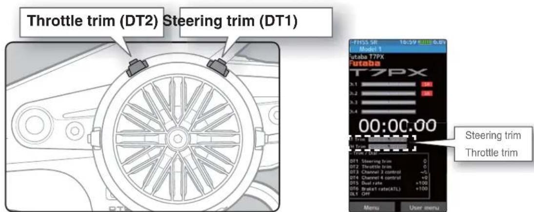
- Steering trim (DT1) check
On the initial set-up, steering trim is assigned to the DT1 trim lever above. Operate the lever and make sure the marker moves on the ST graph. If default has been changed, test steering trim in its new location. After checking the trim, set the trim display to the center (N) position.
- Throttle trim (DT2) check
On the initial set-up, throttle trim is assigned to the DT2 trim lever. Operate the lever and make sure the marker moves on the TH graph. If the default has been changed, test throttle trim in its new location. After checking the trim, set the trim display to the center (N) position.
- Steering dual rate (DT5) check
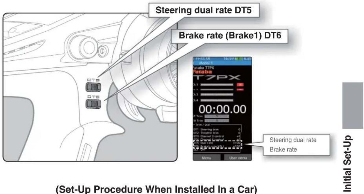
At initial set-up, steering dual rate (D/R) is assigned to DT5 trim lever, at the grip of transmitter. Operate the DT5 and check if the D/R value displayed on the screen changes. After checking D/R, set the steering dual rate to 100%.
- Brake rate (DT6) check
At initial setting, brake rate (Brake 1 rate) is assigned to DT6 trim lever, below DT6. Operate the DT6 and check if the brake 1 rate value displayed on the screen changes. After checking brake 1 rate, set brake rate to 100%.
When installing the servos in a car, performing function set-up in the following order: recommended.
1 Initialize all the trims to zero / dual rate to 100.
2 Set the servo direction of operation using the Reverse function. (page 53)
- The servo installation method and linkage direction depend on the kit. Therefore, the servo operation direction may have to be reversed relative to transmitter operation. Before installing the servo, check the operating direction and set it using the Reverse function.
3 Set the sub trim and adjust the servo neutral point. (page 54)
4 Set the trigger travel by adjusting the throttle trigger mechanical ATL to your liking. (page 22)
- When the stroke was adjusted, compensate the throttle by calibration function (page 184).
5 Set end point of each channel and adjust the servo throw (travel). (page 55)
Menu Selection
Use the HOME button and the LCD screen touch panel to operate the screen. In this operation manual, the HOME button is indicated by the following symbols.
Display Menu Screen
![Push the HOME button or tap the touch panel. Press and hold the HOME button. Tap [User Menu] on the home screen to display the "User menu" screen. FHSS SR 16:59 GMT 6.8V Model 1 Futaba T7PX T7PX 00:00.00 IT Trim IT Trim -Trim / Dual DT1 Steering trim 0 DT2 Throttle trim 0 DT3 Channel 3 control +0 DT…](/content/2026/07/1443791/images/921858485c692e2655869a6f73d0dd6ab2f0282d0dc89b570cbb182243d1b6f8.jpg)
It returns to the "Home screen" from the function screen in the following method.
![graph TD A["Start"] --> B["Linkage menu"] B --> C["Sub trim"] C --> D["End point"] D --> E["Fail-safe"] E --> F["Acceleration"] F --> G["Telemetry menu"] G --> H["Accessory menu"] H --> I["Fanaba T7PX Interface"] I --> J["End Point Screen Return"] J --> K["End Point Screen Return to Home Screen"] K…](/content/2026/07/1443791/images/afac82bf4b97d04166b7b0c1f972be2496ab24141b839baa988bbe49e93d382e.jpg)
(Home screen)(End point screen)
Home Button Setting
When you push the HOME button from the home screen, it moves to the menu screen at the factory shipping the HOME button. Pushing the HOME button on the menu screen or each setting screen will return you to the previous screen. Also, if you press and hold the HOME button on the Home screen, the trim lock will work and the T7PX can prohibit operations with the digital Trim DT1 to DT6 and Dial DL1 on the main unit. Press and hold the HOME button on the menu screen or each setting screen to return to the Home screen. The setting screen moved from the custom menu also moves in the same way and returns to the home screen.
You can select the screen to display when you push the HOME button on the Home screen, menu or user menu. You can not change the screen to display by push and holding the HOME button from the menu screen or each function screen.
- Push----Display menu screen or custom menu screen.
- Long press----Trim lock or display the function screen of your choice.
"Home button setting" of "Accessory menu" (page 151)
![graph LR A["Menu"] --> B["System menu"] B --> C["Model menu"] C --> D["Linkage menu"] D --> E["Racing menu"] E --> F["Mixing menu"] F --> G["Telemetry menu"] G --> H["Accessory menu"] I["Accessory menu"] --> J["Timer"] J --> K["Lap list"] K --> L["S.Bus servo"] L --> M["MC(ESC)-Link"] M --> N["Roll…](/content/2026/07/1443791/images/b861a2dc18659df1c44d534de4c570587959568939b609541ed62c57630fbe7a.jpg)
(Menu screen) (Accessory menu screen) (Home button setting screen)
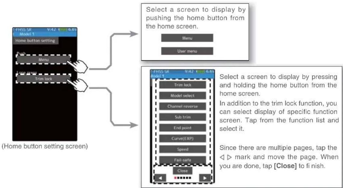
Value Of Each Function And Changing The Set Value
On the setting screen of each function, if you tap the item to be set, [-] [reset] [+] will be displayed at the bottom of the screen, tap the [-] [+] on the panel Set. Tap[Reset] to return to the initial value. There are items with no [reset].
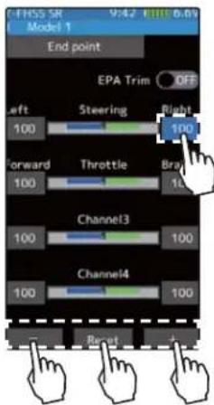
Example: To change the right-hand side steering amount on the end point screen, tap the right of the steering wheel, and when [-] [reset] [+] is displayed at the bottom of the screen, press + To decrease, tap [-] to change the numerical value. If you leave it tapped, the value changes continuously. Tap [Reset] to return to the initial value.

When resetting is executed, a confirmation screen is displayed. To reset, tap [Yes], otherwise tap [No].
The setting of ON / OFF changes when you tap (ON) or (OFF).
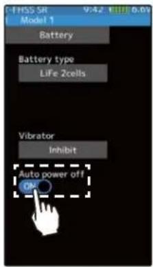
Example: When turning off the auto power off function on the battery setting screen, tap (ON) of auto power off to display (OFF) and the function will be invalid.
To select a function form multiple items such as language, tap the function on the screen. Then, choose/tap the item from a pop-up screen that is coming to show the item selection.

Example: tap the 'System Menu' button and 'Information' button for the systems information. Within this group you can select different languages. English, Japanese, German, French, Spanish, Czech, Italian. If you do not wish to change from default, press cancel.
* Depending on the function, items may be switched in order by tapping.
User Menu
The T7PX allows you to register your favorite functions in the user menu. You can create a different user menu for each model memory, and the user menu will also be copied by model copy (page 171). (8 types on a page, up to 48 types on 6 pages)
Displaying And Editing The User Menu Screen
On the user menu screen, you can display the user menu screen by tapping [User Menu] on the home screen. (See page 44)
* It is possible to display by pushing the HOME button "Home that the setting" function.
Menu assignment
1 Tap the [Edit] on the user menu screen. A confirmation screen will appear with "User menu setting Are you sure?" to edit, tap [Yes] to display the edit screen. If you do not want to edit it, please tap [No].
![graph TD A["User menu"] --> B["Edit"] B --> C["Tap [Yes"] to edit, and_tap["No"] to cancel.] C --> D{User menu setting} D -->|Yes| E["Are you sure?"] D -->|No| F["End point"] E --> G["Receiver"]](/content/2026/07/1443791/images/b5d7bfe5c197dd72f5869935c59756cf0b461c6a12fdc373cd43ef1de6e4ecda.jpg)
(User menu screen) (User menu setting screen)
2 Tap the place to register the function. A list of the functions that can be selected will be displayed, so if you tap the function you want to register, it will be registered.
![graph LR A["User menu setting"] --> B["Tap the place to register."] B --> C["Model selection"] C --> D["Tap the function to register."] D --> E["Edit User Menu with exit."]](/content/2026/07/1443791/images/a62d530748e704d5f27683f97ecf7e70ec4e20d5dd0cb8f68f49912b63d6d862.jpg)
(User menu setting screen) (Function list screen)
3 Tap [Edit User Menu] to exit and return to the user menu screen.
Function Map
| Function List | ||
| Function Name | Description Of Function Page | |
| Display | Backlight brightness setting / dimming time setting / touch panel correction | 176 |
| Information | Language setting / version information | 178 |
| Sound | Sound setting (telemetry sound, alarm sound, operating sound) | 180 |
| Battery | Battery type setting / Auto power off ON / OFF | 181 |
| Date And Time | Date and time setting / Displaying the time on the home screen or selecting the total timer | 182 |
| LED Setting | Pilot LED on/off | 183 |
| Calibration | Steering wheel and throttle trigger correction | 184 |
| Software Update | Updated with terminal app on NFC | 186 |
| Model Select | Model memory call | 170 |
| Model Copy | Model memory copy | 171 |
| Model Name | Model memory name set/modify | 173 |
| Model Delete | Delete model data in SD card | 174 |
| Data Reset | Model memory reset (Model, Direct menu, All) | 175 |
| Receiver | Receiver system/servo response selection/linking with T-FHSS SR & T-FHSS system receive/Telemetry ON / OFF | 37/52 |
| Servo View | Displays servo operation on a bar graph | 64 |
| Trigger | Neutral brake and throttle servo forward side and brake side operation rate setting | 62 |
| Channel Reverse | Servo operation reversing | 53 |
| Sub Trim | Servo center position fine adjustment | 54 |
| End Point | End point adjustment | 55 |
| Fail-safe/Battery Fail-safe | Fail safe, battery fail safe | 58 |
| Acceleration | Reduces the "lag time" of the throttle from the neutral position. | 60 |
| Trim / Dial Select | Selection of functions operated by digital dial and digital trim | 66 |
| Switch Select | Selection of functions operated by push switches | 69 |
| Condition | 2ND condition | 76 |
| Idle-Up | Idle up at engine start | 72 |
| D/R,ATL | Steering angle adjustment while running/ Brake side adjustment | 65 |
| Function Description Of Function Page | ||
| Channel Limiter | A channel limiter function which limits maximum servo movement. | 74 |
| Channel Setting | Ability to assign steering or throttle motion to any channel. | 75 |
| Curve (EXP) | Steering curve adjustment / Throttle curve adjustment | 78 |
| Speed | Steering servo delay / Throttle servo delay | 84 |
| Traction Control | Pulse throttle operation. | 95 |
| A.B.S | Pulse brake | 90 |
| Start | Throttle preset at start function | 99 |
| Engine Cut | Engine cut off by switch | 101 |
| Steering Mixing | Twin servo mixing of the steering | 103 |
| Brake Mixing | Front and rear independent brake control for 1/5GP car, etc. | 106 |
| Gyro Mixing | The sensitivity of Futaba car rate gyros can be adjusted | 110 |
| 4WS Mixing | 4-wheel steering mixing | 113 |
| Dual ESC | Front and rear ESCs mixing | 116 |
| CPS Mixing | The CPS-1 of Futaba LED controller can be adjusted. | 118 |
| Tank Mixing | For Tank mixing | 120 |
| Program Mixing 1-5 | Programmable mixing between arbitrary channels | 122 |
| Tilt Mixing | Outboard engine tilt mixing | 125 |
| Telemetry | Telemetry data screen | 153 |
| Sensor List | Telemetry sensors list | 162 |
| Sensor Menu | Telemetry sensors setting | 164 |
| Timer | Up, down, lap, or lap navigation timer | 127 |
| Lap List | Lap timer data (lap time, average lap, best lap time) check | 134 |
| S.BUS Servo | S.BUS servo Link software setting / SR mode setting | 135 |
| MC (ESC) Link | MC851C/602C/402CR/950CR/940CR/960CR Link software setting function | 140 |
| Roll Out Chart | For pan cars roll out chart | 149 |
| Gear Ratio Chart | Gear ratio calculation function. | 150 |
| Home Button Setting | Change the function of the HOME button | 151 |
Function map
![graph TD A["Home screen"] --> B["Linkage menu-1"] B --> C["Linkage menu-2"] C --> D["Model menu"] D --> E["Telemetry menu"] subgraph Function Map F1["Receiver 37/52"] --> G1["Servo view 64"] --> H1["Trigger 62"] --> I1["Channel Reverse 53"] F2["Sub trim 54"] --> G2["End point 55"] --> H2["Fail safe…](/content/2026/07/1443791/images/1d937f8eaa88015f09544373422e227fae4ce5c3b9b2ca3931276eaca6b4a2ad.jpg)
Function map
![graph TD A["Home screen"] --> B["Racing menu"] B --> C["Curve(EXP) 78"] C --> D["Speed 84"] D --> E["Traction control 95"] E --> F["A.B.S 90"] F --> G["Start 99"] G --> H["Engine cut 101"] A --> I["Menu screen"] I --> J["Mixing menu-1"] J --> K["Steering mixing 103"] K --> L["Brake mixing 106"] L --…](/content/2026/07/1443791/images/1fb6ead4cc6b7fa6c5e8afc108a45e9732716fdaeaac83e0bea5881dc8f1e25d.jpg)
Receiver
This menu selects the settings matched to the receiver system used and the type of servo and the items selected at the T7PX, linking of the T7PX with the T-FHSS telemetry system, and ON/OFF.
The receiver setting and selection and linking of the T7PX transmitter with T-FHSS SR, T-FHSS telemetry system receiver are described on page 37 to 41.
![graph TD A["Home screen"] --> B["Menu screen"] B --> C["Linkage menu"] C --> D["Menu-1"] C --> E["Menu-2"] D --> F["Receiver"] E --> F F --> G["Receiver ID: T-FHSS 9.42 0.01 0.05"] G --> H["Digital servo: Link response"] H --> I["Telemetry ON"] I --> J["User icon"] J --> K["User icon"] K --> L["User…](/content/2026/07/1443791/images/7f1211a952c56796d02bc0f4a6eee1e4a04b04ffacd037af2be6b8ca6335a6c4.jpg)
Telemetry function ON/OFF
1 (Function ON/OFF)
Tap telemetry (ON) or (OFF) to select ON / OFF.
"OFF": Telemetry function OFF
"ON": Telemetry function ON

Telemetry function ON
Setting
- Tap (ON) / (OFF).
2 When finished, return to the Linkage menu screen by pressing the HOME button.
Channel Reverse
This function reverses the direction of operation of the servos related to transmit steering, throttle, channel 3, channel 4 and auxiliary channels operation.
However, when the position set by trim or sub trim shifts from the center, the center becomes the opposite side.
![graph TD A["Home screen"] --> B["Menu screen"] B --> C["Linkage menu"] C --> D["Menu-1"] C --> E["Menu-2"] D --> F["Channel reverse"] E --> F F --> G["Tap to change page."] G --> H["Channel 1: Normal, Reverse Channel 1 N"] G --> I["Channel 2: Normal, Reverse Channel 2 N"] G --> J["Channel 3: Normal,…](/content/2026/07/1443791/images/157ed59aca718f7fbed05d78729d29893aaab9cd275893e73268c28503b8f8e2.jpg)
Servo Reverse Function Setting
1
(Servo reverse setting)
Tap the desired channels setting button to choose the proper direction for the servo.
(Each channel can be set similarly.)

Setting
- Tap (R) / (N).
(N) Normal / (R) Reverse
2
When fi nished, return to the Linkage menu screen by pressing the HOME button.
Sub Trim
Use this function to adjust the neutral position of the steering, throttle, channel 3, channel 4 and auxiliary channels servos.
![graph TD A["Home screen"] --> B["Menu screen"] B --> C["Linkage menu"] C --> D["Sub trim"] D --> E["Tap to change page."] E --> F["Sub trim adjusts the entire range of the servo in the set direction."] F --> G["Use to adjust the neutral position"] style A fill:#f9f,stroke:#333 style B fill:#ccf,stro…](/content/2026/07/1443791/images/09897629a797333c5214c4f3e06863a0580f569a5f4306f0a115da744b41d128.jpg)
Sub trim adjustment
(Preparation)
- Follow the instructions of the model, install the servo horn and make the next adjustment.
- Set the steering and throttle digital trims to the neutral "0" position. Set auxiliary channels to the center "0" position.
- Tap the trim display part of the channel you want to adjust. Value input buttons appear on the Sub-trim menu screen.
Adjustment buttons
- Adjust with the [+] and [-] buttons.
- Return to the initial value by tapping the [reset] buttons.
Sub trim
-100\~+100
Initial value : 0

1 (Sub trim adjustment)
Use the [+] or [-] button to adjust the center.
(Each channel can be set similarly.)
2 When fi nished, return to the Linkage menu screen by pressing the HOME button.
End Point
Use this when performing left and right end point adjustments, throttle high side/brake side operation amount adjustment, channel 3, channel 4 and auxiliary channels servos up side/down side operation amount adjustment.
- Correct the maximum steering angle for left and right steering angles when there is a difference in the turning radius due to the characteristics of the vehicle.
Maximum steering angle
The End point function basically determines the maximum steering angle of each channel.
The functions shown below may have been adjusted or the operating range set by End point function may be exceeded. Check the linkage each time the following functions are adjusted.
- Sub trim (all channels)---- page 54
- Program mixing slave side (all channels) ----page 122
- Idle up (throttle)---- page 72
- Engine Cut (throttle) --page 101
- Throttle acceleration (throttle)---- page 60
Brake rate trim
Brake rate trim allows adjustment of the brake side operation amount during operation. Therefore, when the operating angle is adjusted with throttle End point, brake rate trim must also be taken into account.
⚠ Warning
Operate each servo over its full stroke and be sure the linkage does not bind or is not loose.
The continuous application of unreasonable force to a servo may cause damage and excessive battery drain.

Adjust the steering servo so that unreasonable force is not applied to the servo by the chassis at maximum servo travel.
Decide the End point value at the contact point.

Adjust the throttle servo so that unreasonable force is not applied when the engine carburetor is fully open, fully closed, and the brakes are applied fully.
If the brakes overheat while running, their ability to function properly decreases. Before running, adjust the suitable maximum servo travel so that unreasonable force is not applied even when the servo travel is increased while running.
![```mermaid graph TD A["Home screen"] --> B["Menu screen"] B --> C["Linkage menu"] C --> D["End point"] D --> E["Tap to change page."] subgraph Home Screen F["Home Screen 00:00.00"] G["Menu 1"] H["Menu 2"] end subgraph Menu Screen I["Menu 1"] J["Menu 2"] end subgraph Linkage Menu K["Menu-1"] L["Menu-…](/content/2026/07/1443791/images/ec8f2de2052c331a8a5f56331e6a39f23956580dde4e52c2bdff3ef352c877cf.jpg)
Steering end point adjustment
(Preparation)
- Before setup of the steering end point adjustment, set the steering D/R dial (initial setup: DT5) to the maximum steering angle position 100%.
- Tap the travel button of the [Steering Left]. Value input buttons appear on the screen and make the following adjustments:
1 Steering (left side) adjustment
Turn the steering wheel fully to the left and use the [+] or [-] buttons to adjust the steering angle.
2 Steering (right side) adjustment
Turn the steering wheel fully to the right and use the [+] or [-] buttons to adjust the steering angle.
Note

Step #1 & #2 are done when the receiver is in the on position installed on the chassis. You're watching the wheels reach their maximum end point.
3 When fi nished, return to the Linkage menu screen by pressing the HOME button.
For S-FHSS (analog) system, channels 5, 6 and 7 are displayed on the 2nd page.
Adjustment buttons
Adjust with the [+] and [-] buttons.
- Return to the initial value by tapping the [reset] buttons.
Steering End point :0\~140 Initial value :100

Quick EPA
When EPA trim is turned on, the steering angle (end point) can be adjusted by steering trim set digital trim or dial. (Steering trim initial setting: DT1)

Steering left side adjustment
With the steering wheel turned fully to the left, steering is adjusted by steering trim. Temporarily displayed at this part of the HOME screen as shown in the figure below.

Steering right side adjustment
With the steering wheel turned fully to the right, steering is adjusted by steering trim. Temporarily displayed at this part of the HOME screen as shown in the figure below.
Throttle end point adjustment
(Preparation)
- Before setting the throttle end point adjustment, set the throttle ATL dial (initial setup: DT6) to the maximum throttle angle position 100%.
- Tap the travel button of the [Throttle Forward]. Value input buttons appear on the screen and make the following adjustments:
1 Throttle (forward side) adjustment
Pull the throttle trigger fully to the high side and use the [+] or [-] buttons to adjust the throttle angle. However, when using an ESC, set to 100%.

2 Throttle (brake side/reverse side) adjustment Move the throttle trigger fully to the brake side and use the [+] or [-] buttons to adjust the throttle angle. However, when using an ESC, set to 100%.

3 When finished, return to the Linkage menu screen by pressing the HOME button.
Adjustment buttons
- Use the [+] and [-] buttons to make adjustments.
- Return to the initial value by tapping the [reset] buttons.
- Please see previous note on page 56.
Throttle End point :0\~140
Initial value :100

When Trigger Ratio (page 62) was set to 100:0, brake operation is stopped and the throttle (brake side) cannot be adjusted.
Auxiliary channel servo end point adjustment
(Preparation)
- Tap the travel button of the channel you want to set. Value input buttons appear on the screen.
1 Use the [+] or [-] buttons to adjust the servo angle.
Adjustment buttons
- Use the [+] and [-] buttons to make adjustments.
- Return to the initial value by tapping the [reset] buttons.
- Please see previous note on page 56.
Auxiliary channel End point
:0\~140
Initial value :100

Spare channel display
When a mixing function is set at a spare channel, the display changes.
This is an example of setting dual ESC mixing at the 3rd channel and 4WS mixing at the 4th channel.
Dual ESC mixing : Front ESC
4WS mixing: Rear servo

2 When finished, return to the Linkage menu screen by pressing the HOME button.
Fail-safe/ Battery Fail-safe
This function sets the servo operation position when transmitter signals cannot be received by the receiver for some reason or the battery voltage has dropped.
-Fail safe mode
This function moves each servo to a preset position when the receiver cannot receive the signals from the transmitter for some reason.
* The fail safe data is transferred from the transmitter to the receiver 10 seconds after the transmitter power was turned on.
* The data is transferred every 10 seconds after that. Be careful because normally the transmitter power is turned on first and the receiver power is turned on next and there is no data transfer for about 10 seconds after the receiver power is turned on.
* For gasoline engine cars, for safety we recommend that this fail safe function be used to set the throttle channel in the direction in which the brakes are applied.
-Hold mode
This function holds the receiver in its position immediately before reception was lost.
-Off mode (OFF)
This function stops output of signals to the servos and places the servos into the free state when the receiver cannot receive.
The F/S, HOLD, and OFF modes are automatically reset when signals from the transmitter can be received again
-Battery fail safe function (B-F/S)
If the receiver battery voltage drops below a certain value when this function is enabled, the throttle servo moves to the position set by fail safe function. When the battery voltage recovers, the battery fail safe function is automatically reset.
* This function cannot be used when the channel is not set to fail safe.
* When the receiver setting (page 37) is "FASST", only Ch.2 (throttle) can use this function.
![graph TD A["Home screen"] --> B["Menu screen"] B --> C["Linkage menu"] C --> D["Menu-1"] C --> E["Menu-2"] D --> F["Fail-safe"] E --> F F --> G["FHSS SR 9:42 6.0V"] style A fill:#f9f,stroke:#333 style B fill:#ccf,stroke:#333 style C fill:#cfc,stroke:#333 style D fill:#fcc,stroke:#333 style E fill:#c…](/content/2026/07/1443791/images/1ad5c2e6a41151932e865f2effc60abf094242bc84aa32a12044e92fcb76e210.jpg)

For S-FHSS (analog) system, channels 5, 6 and 7 are displayed on the 2nd page.
* When fail safe is set, that servo position is displayed.

Servo position

Receiver setting
FASST
Fail safe mode selection
(Preparation)
- Tap the fail safe part of the channel you want to set. The mode list appears on the Fail-safe menu screen.
1 (Mode selection)
Tap from the list and select the mode. To cancel, tap [Cancel].
(Each channel can be individually set.)
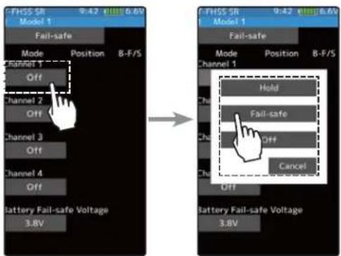
Fail safe mode
Off, Hold, Fail-safe
2 When finished with hold or off mode setting, return to the Linkage menu screen by pressing the HOME button. When setting fail safe, set the servo position by the following method.
Fail safe function setup
1 (Servo position setup)
Tap the [Mode] button of the channel you want to set, and set that channel to the Fail-safe mode.
Hold the corresponding steering wheel, throttle trigger, or other control in the position you want the servo to move to when the fail safe function is activated, and tap the [Position] button. The position is displayed as a value.
2 When finished, return to the Linkage menu screen by pressing the HOME button.

Fail-Safe position setting
While holding the wheel or trigger, tap the Fail-Safe position button.
B-F/S function ON/OFF & Battery Fail-safe voltage setting
1 (Battery fail safe function ON/OFF)
Tap B-F /S (ON) or (OFF) of each channel to select ON / OFF.
2 (Battery fail safe voltage setting)
Tap the voltage display of battery fail safe voltage. Value input buttons appear on the Fail-Safe menu screen.
Use the [+] or [-] button to select the voltage.
* Voltage setting is not possible with the S - FHSS system fixed at 3.8 V.
* Since FASST R604 Series receivers are not for high voltage use, the use of LiFe and Li-Po batteries is prohibited. Therefore, the 4.75V and 5.5V settings are prohibited. The 5.5 V setting of the FASST system can only be used by the receiver with R614FS (FSE).

Battery fail safe function
OFF, ON
Initial value: OFF
Battery Fail-safe Voltage
T-FHSS SR/T-FHSS
3.8,4.0,4.2,4.4,4.6,4.8,5.0,
5.3,5.6,5.9,6.2,6.5,6.8,7.1,7.4V
FASST
3.5,3.8,4.4,4.75
5.5V(Only R614)
S-FHSS
Only 3.8V
Example:
Ni-MH /Ni-Cd 4cell---3.8V
Ni-MH /Ni-Cd 6cell---4.4V
LiFe 2cell---4.75/4.8V
Li-Po 2cell---5.5/5.6V
3 When finished, return to the Linkage menu screen by pressing the HOME button.
When the receiver power supply of an electric car uses a common power supply from an ESC, we recommend that this function be set to OFF because the voltage supplied to the receiver may drop momentarily and the battery fail safe function may be activated.
Acceleration
The servo will jump to the input position at its maximum possible speed. Unlike exponential, which adjusts the whole throttle movement into a curve, throttle acceleration sim "jumps" away from neutral and then leaves the remaining response linear.
Operation
- Operation near the throttle trigger neutral position becomes a sharp rise.
- The forward and brake sides can be set separately.
- When the brake mixing function (page 80) set, the auxiliary channel brake can also be set.


Set value
The standard value (100% point) of this setup affects the operation amount set by throttle end point function.
Convenient usage method
For gasoline engine cars, the linkage must have a clearance because one servo controls the engine carburetor and brake. Thus, there is a noticeable time delay at both the forward and brake. Sharp response comparable to that of electric motor cars is obtained by reducing this clearance at the transmitter side.

![graph TD A["Home screen"] --> B["Menu screen"] B --> C["Linkage menu"] C --> D["Acceleration"] D --> E["Output"] subgraph Home Screen F["7PX 00:00.00"] end subgraph Menu Screen G["Menu 1"] H["Menu 2"] end subgraph Linkage Menu I["Menu-1"] J["Menu-2"] end subgraph Acceleration K["Forward 0"] L["Brake…](/content/2026/07/1443791/images/0ed954685583203ebdfb37a0f4955ce152be0f646624417700f81b6388e98d33.jpg)
Throttle acceleration adjustment
(Preparation)
- Tap the value button of the [Forward]. Value input buttons appear on the screen and make the following adjustments:
1 (Forward acceleration amount adjustment) Use the [+] and [-] buttons to adjust the acceleration amount.
"0": No acceleration
"100": Maximum acceleration (Approximately 1/2 of the forward side throttle angle)

Adjustment buttons
Adjust with the [+] and [-] buttons.
- Return to the initial value by tapping the [reset] buttons.
Forward acceleration amount (Forward)
0\~100
Initial value: 0
2 (Brake side acceleration amount adjustment) Tap the travel button of the [Brake 1]. Value input buttons appear on the screen and use the [+] and [-] buttons to adjust the acceleration amount.
"0": No acceleration
"100": Maximum acceleration (Brake side maximum throttle angle)
If the "Brake Mixing Function" (page 106) is being set, the auxiliary channel brake side acceleration will become adjustable.

Brake side acceleration amount (Brake1)
0\~100
Initial value: 0

Brake 2 Brake 3 Brake 2&3

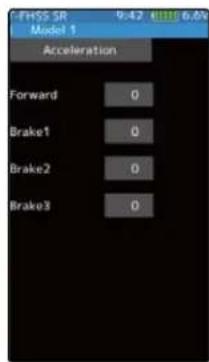

3 When finished, return to the Linkage menu screen by pressing the HOME button.
Caution
When Trigger Ratio (page 62) was set to 100:0, brake operation is stopped and the throttle (brake side) cannot be adjusted.
Dial / Trim Setting
The throttle acceleration adjustment amount (Forward), (Brake 1), auxiliary ch (Brake 2, Brake 3) can be controlled with digital trim DT1-DT6 or digital dial DL1 etc. with the dial select function. (page 66)
Trigger
This menu has the following 2 functions:
-Servo neutral mode:
This function allows selection of the forward side and brake (reverse) side operation ratio from 70:30, 50:50 or 100:0 by changing the neutral position of the throttle servo.
-Neutral brake:
This is a function select switch function. The neutral brake function ON/OFF switch must be set (see page 69).
The neutral brake, which applies the brakes at the neutral position of the throttle trigger can be set. However, when using the MC950CR, MC851C, MC602C, MC402CR, or other Futaba ESC, confirm that the ESC is in the neutral position and the set is in the operation mode before setting the neutral brake function switch to ON.
![graph TD A["Home screen"] --> B["Menu screen"] B --> C["Linkage menu"] C --> D["Trigger"] subgraph Home Screen E["7PX 00:00.00"] F["User Interface"] end subgraph Menu Screen G["Menu 1"] H["Menu 2"] end subgraph Linkage Menu I["Menu-1"] J["Menu-2"] end subgraph Trigger K["Trigger"] L["Trigger"] M["Tr…](/content/2026/07/1443791/images/4765c0daf9eba7896777b9463c89cda02c1ce9c11f6d1ba7184d1588440cad88.jpg)
Throttle servo neutral position "Ratio"
Forward 50: Brake 50

Forward 70: Brake 30

Forward 100: Brake 0
Selecting the trigger ratio
1 (Throttle mode selection)
- Tap the [Ratio] part.
The mode list appears on the Trigger menu screen.
Tap from the list and select the mode. To cancel, tap [Cancel].
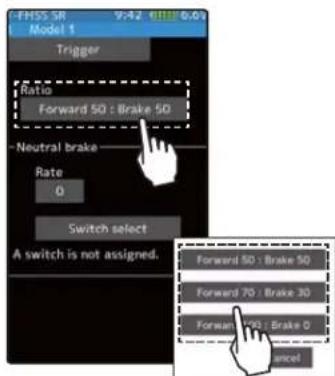
Ratio mode
Forward 50:Brake 50
Forward 70:Brake 30
Forward 100:Brake 0
2 When finished, return to the Linkage menu screen by pressing the HOME button.

Neutral Brake function adjustment
(Preparation)
- Use the switch select function to the "Switch select". (page 69) When the switch is not set "A switch is not assigned" is displayed. Tap [Switch select] to display the switch selection screen and set the switch.
1 (Neutral brake rate)
Tap the value button of the [Rate]. Value input buttons appear on the screen and use the [+] and [-] buttons to adjust the neutral brake rate amount.


Adjust button
Adjust with the [+] and [-] buttons.
- Return to the initial value by tapping the [reset] buttons.
Neutral Brake
0\~100
Initial value: 0
2 When fi nished, return to the Linkage menu screen by pressing the HOME button.

Neutral brake ON/OFF is indicated on the home screen for a few seconds.
When the neutral brake is ON, the display of the throttle trim on the home screen becomes the neutral brake.
It is displayed in the home screen, when the neutral brake is ON.
If the power switch turned on while the neutral brake switch is an audible alarm will be heard. Immediately the neutral brake switch to OFF.

Reference
The ESC neutral brake function and T7PX neutral brake function can be used simultaneously. However, when setting is difficult to understand, we recommend that neutral brake function be used.

Function
Dial / Trim Setting
When the neutral brake function is "ON", the neutral brake rate adjustment is automatically assigned to the throttle trim (DT1 to DT6 or DL1).
Effect of set value of other functions on neutral brake
Throttle side EPA function, or ATL function setting also affects neutral brake side operation. The Idle-up (page 72) or Engine Cut (page 101) function has priority.
Servo View
Servo operation of each channel can be checked. Operation of the steering angle adjustment, when a mixing function was set, etc. can be easily checked.
![graph TD A["Home screen"] --> B["Menu screen"] B --> C["Linkage menu"] C --> D["Menu-1"] C --> E["Menu-2"] D --> F["Servo view"] E --> F F --> G["Servo view"] G --> H["Servo view"] H --> I["Servo view"] I --> J["Servo view"] J --> K["Servo view"] K --> L["Servo view"] L --> M["Servo view"] M --> N["…](/content/2026/07/1443791/images/61194e5fc17c0a3cbbc2d2009691d745b70b7c0782d04c53bb3f3031f5cb48ad.jpg)
For S-FHSS (analog) system, channels 1 through 7 are displayed.
Confir rm operation
1 Operating each channel, such as a steering wheel or throttle trigger, the graph moves and the servo operation can be confirmed.
2 When fi nished, return to the Linkage menu screen by pressing the HOME button.
D/R, ATL
D/R (Steering dual rate)
The steering left and right servo travels are adjusted simultaneously. This setting is linked to transmitter grip trim DT5. When DT5 is assigned another function, dual rate can be adjusted with this screen.
ATL (Brake 1 rate)
This function decreases the set value when the braking effect is strong and increases the set value when the braking effect is weak. This function is linked to transmitter grip trim DT6. When DT6 is assigned another function, this function can be set with this screen.
![graph TD A["Home screen"] --> B["Menu screen"] B --> C["Linkage menu"] C --> D["Menu-1"] C --> E["Menu-2"] D --> F["D/R, ATL"] E --> F F --> G["D/R, ATL Model 1"] G --> H["D/R, ATL"] H --> I["Brake1 rate(ATL) 100"] I --> J["Device 1: Dual rate"] J --> K["Device 2: Dual rate"] K --> L["Device 3: Dual…](/content/2026/07/1443791/images/51f2769fa23b0c53ec21400029557adaace7aca8ec1876459caeacf705bc8bdb.jpg)
Dual rate adjustment
1 Tap the travel button of the [Dual rate]. Value input buttons appear on the screen and use the [+] and [-] buttons to adjust the dual rate amount.
This dual rate servo travel is linked to the grip trim.
When finished, return to the Linkage menu screen by pressing the HOME button.

Brake rate (ATL) adjustment
1 Tap the travel button of the [Brake rate (ATL)]. Value input buttons appear on the screen and use the [+] and [-] buttons to adjust the brake rate amount.
This brake rate servo travel is linked to the grip trim.
When finished, return to the Linkage menu screen by pressing the HOME button.

Adjust button
Adjust with the [+] and [-] buttons.
- Return to the initial value by tapping the [reset] buttons.
Dual rate
0\~100
Initial value: 0

Adjust button
Adjust with the [+] and [-] buttons.
- Return to the initial value by tapping the [reset] buttons.
Brake rate(ATL)
0\~100
Initial value: 0
Trim / Dial Select
This function allows selection of the function performed by the digital dial DL1 and digital trimmers (DT1 to DT6), step amount adjustment, and operating direction reversal.
- The table in page 68 lists the functions that can be assigned to each dial and digital trim. The assigned function is also displayed on the opening screen together with the current adjustment value. They are displayed in DL1 and DT1 to DT6 order, from top to bottom.
- The step amount can be adjusted. The table in the following page shows the relationship between set value and step amount.
- The operation direction can be reversed. (Nor/Rev)
![graph TD A["Home screen"] --> B["Menu screen"] B --> C["Linkage menu"] C --> D["Menu-1"] C --> E["Menu-2"] D --> F["Trim / Dial select"] E --> F F --> G["Off"] G --> H["Balance 1 rate(ATL)"] H --> I["Channel setting"] I --> J["Channel timer"] J --> K["Channel reverse"] K --> L["Trigger"] L --> M["Se…](/content/2026/07/1443791/images/89850510a13b4a88ead659e16a385967d07f9cec31748f36f2db09634af6948e.jpg)
Function select dial setup
1 Tap the trim or dial you want to set. (DT1, 2, 3, 4, 5, 6 / DL1)
The function list appears on the Trim/Dial select menu screen.
Function list See page 68
2 (Function setup)
Tap and select the function you want to use. To cancel, tap [Close].

(Changing the operation direction)
Tap [Nor.] or [Rev.] in the direction to set the direction.
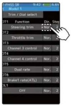
Setting direction
- Tap [Nor.] / [Rev.].
(Nor.) Normal / (Rev.) Reverse
(Changing the operation step amount)
Tap the travel button of the [step]. Value input buttons appear on the screen and use the [+] and [-] buttons to adjust the step amount.

Adjust button
Adjust with the [+] and [-] buttons.
- Return to the initial value by tapping the [reset] buttons.
Step range
1, 2, 5, 10, 20, 30, 40, 50, 100, 200
Initial value: 2
3 When finished, return to the Linkage menu screen by pressing the HOME button.
Relationship between set value and step amount
(Setting range: 1, 2, 5, 10, 20, 30, 40, 50, 100, 200)
-Steering trim/throttle trim
When set to the minimum "1", the total trim operating width is 200 clicks. For "100", the total operating width is 2 clicks and for 2PS, the total operating width is 1 click.
-Rate, etc. setting
This is the % value which is operated by 1 click relative to the set value of each rate. Since the total operating width of functions having a rate of -100\~0\~+100 is 200%, when set to "100", the total operating width is 2 clicks. Since the total operating width of functions with a 0\~100 rate is 100%, "100" and "200" are operated by 1 click.
-Auxiliary channel
When set to the minimum "1", the total operating width of channel 3 is 200 clicks. For "100", the total operating with is 2 clicks and "200" is operated by 1 click.


| Set table functions (DL1/ DT1, DT2, DT3, DT4, DT5, DT6) | ||
| Abbreviation used on setup screen | Abbreviation displayed on opening screen | Function name, etc |
| Steering trim Steering trim | Steering trim | |
| Throttle trim Throttle trim Throttle trim | ||
| Channel 3 to 7 control Channel 3 to 7 control | Channel 3 to 7 control (Channel 5 to 7 is for S-FHSS analog system only.) | |
| Flap Flap Tilt mixing: flap rate | ||
| Dual rate D/R Dual rate function | ||
| Sub trim Ch.1 to 7 Sub trim Ch.1~4 | ||
| Acceleration (forward) Acceleration (forward) Throttle acceleration (Forward side) | ||
| Acceleration (brake 1) Acceleration (brake 1) Throttle acceleration (Brake 1 side) | ||
| Acceleration (brake 2) Acceleration (brake 2) Throttle acceleration (Brake 2 side) | ||
| Acceleration (brake 3) Acceleration (brake 3) Throttle acceleration (Brake 3 side) | ||
| Steering curve | Steering curve | Steering curve (EXP) rate |
| Throttle curve | Throttle curve | Throttle curve (EXP) (Forward side) |
| Steering speed(turn) | Steering speed(turn) | Steering speed (Turn side) |
| Steering speed(return) | Steering speed(return) | Steering speed (Return side) |
| Th speed(turn/high) | Th speed(turn/high) | Throttle speed (High range turn side) |
| Th speed(turn/middle) Th speed(turn/middle) Throttle speed (Middle range turn side) | ||
| Th speed(turn/low) | Th speed(turn/low) | Throttle speed (Low range turn side) |
| Th speed(return/high) | Th speed(return/high) | Throttle speed (High range return side) |
| Th speed(return/middle) | Th speed(return/middle) | Throttle speed (Middle range return side) |
| Th speed(return/low) | Th speed(return/low) | Throttle speed (Low range return side) |
| ABS(return brake 1) | ABS(return brake 1) | Brake 1 A.B.S. function (Return amount) |
| ABS(delay brake 1) | ABS(delay brake 1) | Brake 1 A.B.S. function (Delay amount) |
| ABS(cycle brake 1) | ABS(cycle brake 1) | Brake 1 A.B.S. function (cycle speed) |
| ABS(return brake 2) | ABS(return brake 2) | Brake 2 A.B.S. function (Return amount) |
| ABS(delay brake 2) | ABS(delay brake 2) | Brake 2 A.B.S. function (Delay amount) |
| ABS(cycle brake 2) | ABS(cycle brake 2) | Brake 2 A.B.S. function (cycle speed) |
| ABS(return brake 3) | ABS(return brake 3) | Brake 3 A.B.S. function (Return amount) |
| ABS(delay brake 3) | ABS(delay brake 3) | Brake 3 A.B.S. function (Delay amount) |
| ABS(cycle brake 3) | ABS(cycle brake 3) | Brake 3 A.B.S. function (cycle speed) |
| Traction control(return) | Traction control(return) | Traction control function (Return amount) |
| Traction control(delay) | Traction control(delay) | Traction control function (Delay amount) |
| Traction control(cycle) | Traction control(cycle) | Traction control function (Cycle amount) |
| Brake 1 rate(ATL) | Brake 1 rate (ATL) | Brake 1 rate (ATL) |
| Brake EXP (brake 1) | Brake EXP (brake 1) | Throttle EXP (Brake 1 side) |
| Brake delay (brake 1) | Brake delay (brake 1) | Brake mixing: Brake 1 delay |
| Brake rate (brake 2) Brake2 rate (brake 2) Brake1 rate (Brake 2 side) | ||
| Brake EXP (brake 2) | Brake EXP (brake 2) | Throttle EXP (Brake 2 side) |
| Brake delay (brake 2) | Brake delay (brake 2) | Brake mixing: Brake 2 delay |
| Brake rate (brake 3) Brake2 rate (brake 3) Brake1 rate (Brake 3 side) | ||
| Brake EXP (brake 3) | Brake EXP (brake 3) | Throttle EXP (Brake 3 side) |
| Brake delay (brake 3) | Brake delay (brake 3) | Brake mixing: Brake 3 delay |
| Brake 2,3 rate | Brake 2,3 rate | Brake mixing: Brake 2,3 rate function |
| Tilt mixing (RUD→FLP) | Tilt mixing (RUD→FLP) | Tilt mixing: rudder to flap rate |
| Tilt mixing (FLP→RUD) | Tilt mixing (FLP→RUD) | Tilt mixing: flap to rudder rate |
| Idle up | Idle up | Idle up function rate |
| Prog. mixing 1~5 A | Prog. mixing 1~5 A | Program mixing: rate A side (Left/Forward/Up sides) |
| Prog. mixing 1~5 B | Prog. mixing 1~5 B | Program mixing: rate B side (Right/Brake/Down sides) |
| 4WS rear rate | 4WS rear rate | 4WS mixing: (rear steering rate) |
| Dual ESC | Dual ESC | Dual ESC mixing (Drive mode select) |
| Dual ESC ratio | Dual ESC ratio | Dual ESC mixing: drive ratio (front & rear) |
| Gyro Gain | Gyro | Gyro mixing: (Gain rate) |
| Ackermann rate | Ackermann | Ackermann mixing: (ackermann rate) |
| OFF | Off | Not used |
Switch Select
This function allows selection of the function to be performed by the switches (PS1, PS3, PS4, PS5, PS6, steering wheel, throttle trigger) and setting of the direction, etc. of operation.
- The table on page 71 lists the functions that can be assigned to each push switch.
- The push switch PS6 is integrated with the DL1.
- All switches can be made alternating operations (ON/OFF changes each time SV pressed). (Nor/Alt)
- The ON/OFF direction can be reversed. The reverse select function always starts from the ON state. However, the steering/ trigger switch is different, depending on the p tion. (Nor/Rev)
![graph TD A["Home screen"] --> B["Menu screen"] B --> C["Linkage menu"] C --> D["Switch select"] D --> E["Steering switch (SS)"] E --> F["Trigger switch (TS)"] F --> G["Switch select 2/2"] G --> H["The steering switch and trigger switch are displayed on the 2nd page."] style A fill:#f9f,stroke:#333 s…](/content/2026/07/1443791/images/2e3f2004cf745c96f4be93b11128602473f34939fe89241b440b2d37525ef73a.jpg)
Function select dial setup
1 (Function setup)
Tap the switch you want to set.
(PS1, PS2, PS3, PS4, PS5, PS6/ steering wheel, throttle trigger)
The function list appears on the switch select menu screen. Tap and select the function you want to use. To cancel, tap [Close].


Function list See page 71
Since there are multiple pages, tap the ◀▶ mark and move the page. When you are done, tap [Close] to finish.
2 (Changing the operation direction) Tap [Nor.] or [Rev.] to set the direction.

(Changing the the type of operation) Tap [Nor.] or [Alt.] to set the type.

Setting direction - Tap [Nor.] / [Rev.]. (Nor.) Normal / (Rev.) Reverse
Setting type - Tap [Nor.] / [Alt.]. (Nor.) Normal / (Alt.) Alternate
3 (Steering / trigger switch setting) This is a function that uses the steering wheel and the throttle trigger as a switch.
Tap the set value of the position of the steering switch or trigger switch. Value input buttons appear on the screen and use the [+] and [-] buttons to set the switch ON/OFF position. Alternatively, you can set it by holding the steering wheel or throttle trigger at the point where you turn it ON/OFF and tap the [set]. Fine adjustment is possible with [+] and [-] .
The red range of the bar graph is ON.

Adjust button Adjust with the [+] and [-] buttons. - Return to the initial value by tapping the [reset] buttons.
Steering point 0\~100 Initial value:100
Trigger point -100\~100 Initial value:100
4 When finished, return to the Linkage menu screen by pressing the HOME button.

| Set table functions (PS1/PS2/PS3/PS4/PS5/PS6) & Trigger switch (TS) | |
| Abbreviation used on setup screen | Function name, etc |
| Channel 3 to 7 control | Operation of channel 3 to 7 (Channel 5 to 7 is for S-FHSS analog system only.) |
| Condition 2 2nd condition function ON/OFF | |
| Program mixing (1-5) Program mixing (1-5) function ON/OFF | |
| A.B.S. (Brake 1) A.B.S function brake 1 (2 channel) ON/OFF | |
| A.B.S. (Brake 2,3) A.B.S function brake 2,3 (Auxiliary channel) ON/OFF | |
| Traction control Traction control function ON/OFF | |
| 4WS mixing 4WS mixing function ON/OFF & type select | |
| 4WS type1 (Front) 4WS mixing function type1 (Front) select | |
| 4WS type2 (Reverse) 4WS mixing function type2 (Reverse) select | |
| 4WS type3 (Same) 4WS mixing function type3 (Same) select | |
| 4WS type4 (Rear) 4WS mixing function type4 (Rear) select | |
| Dual ESC (Rear) Dual ESC mixing (Rear Drive mode) | |
| Dual ESC (4WD) Dual ESC mixing (4WD mode) | |
| Dual ESC (Front) | Dual ESC mixing (Front Drive mode) |
| Dual ESC (Rear) Dual ESC mixing (Rear Drive mode) | |
| Gyro mixing | Switching GYRO mode function ON/OFF |
| Gyro gain | Switching GYRO mode (Switch of Gain1 and Gain2 in same group) |
| Gyro group | Switching GYRO mode (Switch of Gain group) |
| CPS mixing (1-3) | CPS up function ON/OFF |
| Brake | Steering mixing (Brake function ON/OFF) |
| Start | Start function trigger wait ON/OFF |
| Engine cut | Engine cut function ON/OFF |
| Idle up | Idle up function ON/OFF |
| Neutral brake | Neutral brake function ON/OFF |
| Timer start | Timer function start /stop |
| Timer reset | Timer function reset |
| Telemetry speech | Telemetry voice guide ON/OFF |
| Telemetry log | Telemetry data logging ON/OFF |
| Screen capture Save images of currently displayed screen to microSD card. | |
| OFF | Not used |
The HOME screen display
When push switch is operated in the HOME screen state, the state of the function is displayed in the center for a few seconds.
Example:
When the push switch to which ON / OFF of the neutral brake is assigned is operated.
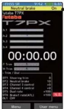
Neutral brake ON/OFF is indicated on the home screen for a few seconds.
Idle-Up
This is a function select switch function. The idle up switch must be set (see page 69).
This function is used to improve engine starting performance by raising the idling s when starting the engine of a GP car (boat). It is also effective when you want to prevent braking when the power is turned off during running, due to the effect of your gear rat setting and choice of motor when operating an electronic car. However, considering safety, and to prevent the motor from rotating instantly when the power is turned on, the MC-950CR, MC851C, MC602C, MC402CR, and other Futaba electronic motor speed controller (ESC) will not enter the operation mode if the neutral position is not confirmed. When using the MC950CR, MC851C, MC602C, MC402CR, or other Futaba ESC, confirm that the ESC is in the neutral position and the set is in the operation mode before setting the idle up function switch to ON.
Operation
The throttle neutral position is offset to the forward side or brake side. There is no link-age locking, etc. Because there is no change near the maximum operation angle even when the neutral position is offset by this function.
![graph TD A["Home screen"] --> B["Menu screen"] B --> C["Linkage menu"] C --> D["Menu-1"] C --> E["Menu-2"] D --> F["Idle-up"] E --> F F --> G["Switch select"] G --> H["Rate: +0 Off"] H --> I["A switch is not assigned."] I --> J["User icon"] J --> K["User icon"] K --> L["User icon"] L --> M["User ico…](/content/2026/07/1443791/images/7c8e6270be91eec5ef1b0049c55d23a07c7f07e517db0e9bb31f46b0a9eed48e.jpg)

If the power switch turned on while the Idle-up switch is on, an audible alarm will be heard. Immediately the Idle-up switch to OFF.

Idle-up function adjustment
(Preparation)
- Use the switch select function to the "Switch select". (page 69)
When the switch is not set "A switch is not assigned" is displayed. Tap [Switch select] to display the switch selection screen and set the switch.

1 (Idle-up rate)
Tap the rate value button. The value input button is displayed on the screen, and use the [+] and [-] buttons to adjust the amount of the neutral brake rate.
![FHSS SR 9,42 0.0% Model 1 Idle up Rate +0 ON Switch *Shows the ON/OFF state Adjust button Adjust with the [+] and tons. - Return to the initial va tapping the [reset] button Idle-up rate -50~0~+50 Initial value: 0](/content/2026/07/1443791/images/c1f457940f3c43eaf0dcf01879c150fc32d77dabaa690b566e579b6619d81b3a.jpg)
Adjust button
Adjust with the [+] and [-] buttons.
- Return to the initial value by tapping the [reset] buttons.
Idle-up rate
-50\~0\~+50
Initial value: 0
2 When finished, return to the Linkage menu screen by pressing the HOME button.
Dial / Trim Setting
The function select dial function can control the Idle-up rate with digital dial or digital trim (page 66).
Channel Limiter
The channel limiter function limits maximum servo movement. By superimposing mixing, the linkage can be protected by setting the limiter in case servo motion becomes unexpectedly large.
![graph TD A["Home screen"] --> B["Menu screen"] B --> C["Linkage menu"] C --> D["Channel limiter"] D --> E["Channel limiter"] E --> F["Tap to change page."] F --> G["S-FHSS (analog) system, channels 5, 6 and 7 are displayed on the 2nd page."]](/content/2026/07/1443791/images/058b3406c459a1390d57e653f7f07e9052d376353f26dbad629cc2dc2332be5b.jpg)
Channel limiter adjustment
(Preparation)
- Tap the travel button of the channel you want to set. Value input buttons appear on the screen.
1 Use the [+] or [-] buttons to adjust the servo angle.

Adjust button
Adjust with the [+] and [-] buttons.
- Return to the initial value by tapping the [reset] buttons.
Limiter rate
0\~145
Initial value: 145
2 When fi nished, return to the Linkage menu screen by pressing the HOME button.
Channel Setting
This function assigns steering or throttle to any channel. You can operate steering and throttle on other channels, and operate other channels in the same way as steering and throttle.
![graph TD A["Home screen"] --> B["Menu screen"] B --> C["Linkage menu"] C --> D["Menu-1"] C --> E["Menu-2"] D --> F["Channel setting"] E --> F F --> G["Channel 1"] F --> H["Channel 2"] G --> I["Channel 3"] H --> J["Channel 4"] I --> K["Control buttons"] J --> K K --> L["User interface"] L --> M["User…](/content/2026/07/1443791/images/2bd61d35117374ba7bd1e9bbfe740b0b69d870b8fec2050a3788c7f26632498d.jpg)
How to select steering / throttle
1 (Channel setup)
Tap the channel you want to set, and the [Steering], [Throttle] setting screen will be displayed. Tap on [Steering] or [Throttle] set for that channel and select it. To cancel, tap [Close].

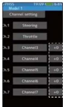
For S-FHSS (analog) system, channels 5, 6 and 7 are displayed.

2 (Position setting of auxiliary channel)
If there is no switch, trim/dial etc. To operate the auxiliary channel, you can set the position here.
Tap the rate display part of the channel you want to adjust. Value input buttons appear on the channel setting menu screen. Use the [+] or [-] button to adjust the position.

Adjust button
Adjust with the [+] and [-] buttons.
- Return to the initial value by tapping the [reset] buttons.
Position
-100\~0\~+100
Initial value: 0
3 When fi nished, return to the Linkage menu screen by pressing the HOME button.
Condition
Two kinds of data can be set in one model for specific functions only; for example, kinds of data such as steering D/R set to 90% at normal condition and steering D/R set to 80% at second condition. This second condition can be set for each model.
-The functions that can be set at each condition are displayed by condition number at the top of the menu screen. Since the reverse function, end point and other model standard setup menus are not displayed by conditioner number, the condition 1 and condition 2 settings are common.
- To use the condition function, switch setting "Switch select" function (page 69) is necessary.
- Switching from normal condition to second condition by switch set by switch select function is indicated by an audible alarm, and the condition number is displayed in the upper on the screen. (The steering switch and the trigger switch are non-audible alarms.)
-First, the initial settings of each condition 2 function are created.
-The data set at condition 2 is memorized until reset by data reset (page 175). The data is memorized even if the condition function is turned off or setting of the switch "Switch select" function is changed.
![graph TD A["Home screen"] --> B["Menu screen"] B --> C["Linkage menu"] C --> D["Menu-1"] C --> E["Menu-2"] D --> F["Condition"] E --> F F --> G["PHSS SR 9.47 mm: 6.6V Model 1"] G --> H["Condition copy"] H --> I["Action buttons"] I --> J["User input"] J --> K["User input"] K --> L["User input"] L -->…](/content/2026/07/1443791/images/c42e0e37ec2fcc65c42027c1d0fedaf408509aea2f8cc92abefa14f071fe1320.jpg)
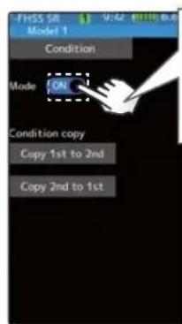
Tap to turn on. When the condition function is turned on, the condition copy display becomes active and the condition is enabled.
Condition adjustment
(Preparation)
- Use the switch select function to the "Switch select". (page 69)
1 (Function ON/OFF)
Tap mode (ON) or (OFF) to select ON / OFF.
"OFF": Function OFF
"ON": Function ON
Condition copy display becomes active and the condition can be used.
Setting
- Tap (ON) / (OFF).
2 (Condition copy)
Tap the condition copy direction. To copy from Condition 1 to Condition 2, tap [Copy 1→2], from Condition 2 to Condition 1, [Copy 2→1]. A confirmation message will be displayed as "Are you sure?". Tap [Yes] to execute, or [No] to cancel.


3 When fi nished, return to the Linkage menu screen by pressing the HOME button.
Display when using condition.
On the function screen which can set the condition and the screen which can not be set, the background color of the number is different.
![graph TD A["Display condition number for a few seconds."] --> B["Condition number"] B --> C1["1: Background Black · Green border"] B --> C2["2: Background Black · Red border"] A --> D1["Condition 1"] A --> D2["Condition 2"] A --> D3["Condition 1"] A --> D4["Condition 2"] B --> E1["00:00.00"] B --> E…](/content/2026/07/1443791/images/1e074dce6a6f6d33fdb2aa3938d82a3feb57a1eb38d2fa67113a91b8dfbf9a24.jpg)
Curve (EXP)
Steering curve
This function is used to change the sensitivity of the steering servo around the neutral position. It has no effect on the maximum servo travel. Al'Finchene" function is which can adjust the rate for left and right separately.
![graph TD A["Home screen"] --> B["Menu screen"] B --> C["Racing menu screen Curve screen"] C --> D["Steering curve"] D --> E["Steering curve"] E --> F["Steering curve"] F --> G["Steering curve"] G --> H["Steering curve"] H --> I["Steering curve"] I --> J["Steering curve"] J --> K["Steering curve"] K…](/content/2026/07/1443791/images/abbbb3587b28e8192990786e640b37c5f0a740e208affb07c6a9f628ab98d7bc.jpg)
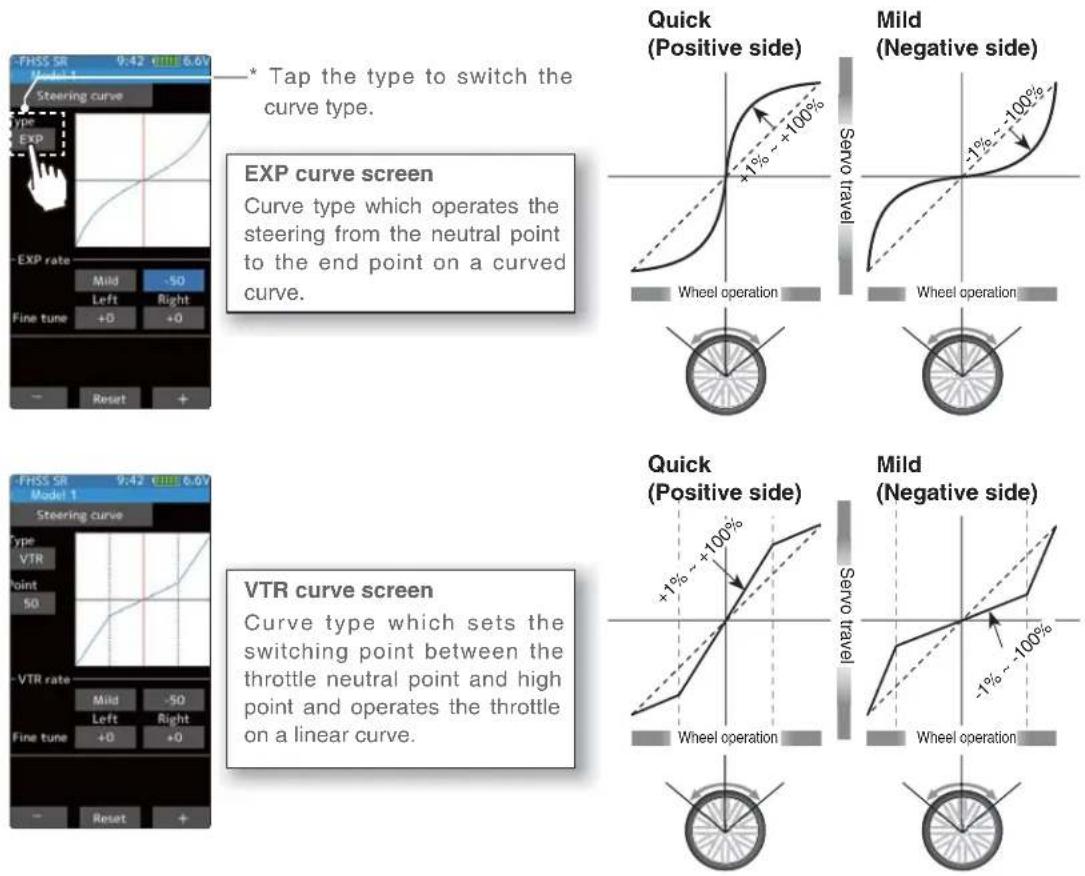
Dial / Trim Setting
The steering EXP, VTR adjustment can be controlled with digital trim DT1 to DT6 or digital dial DL1 etc. with the dial select function. (page 66)

Function
Steering EXP adjustment
(Preparation)
-Tap the curve type and select [EXP].
1 Tap the value button of the [EXP rate] Value input buttons appear on the screen. When you want to quicken steering operation, use the [+] button to adjust the + side. When you want to make steering operation milder, use the [-] button to adjust the - side.
If you tap "Quick" or "Mild" when the value is other than "0", Quick / Mild is reversed.
To set the right and left steering curves separately, tap the rate in the direction you wish to change the setting. Value input buttons appear on the screen, use the [+] or [-] buttons to adjust the steering curve.

Adjustment buttons
- Adjust with the [+] and [-] buttons.
- Return to the initial value by tapping the [reset] buttons.
Curve rate
-100\~+100
Initial value: 0
* The vertical cursor line moves in conjunction with the operation of the steering wheel.
2 When finished, return to the Racing menu screen by pressing the HOME button twice.
Steering VTR adjustment
(Preparation)
-Tap the curve type and select [VTR].
1 Tap the value button of the [VTR rate] Value input buttons appear on the screen. When you want to quicken steering operation, use the [+] button to adjust the + side. When you want to make steering operation milder, use the [-] button to adjust the - side.
If you tap "Quick" or "Mild" when the value is other than "0", Quick / Mild is reversed.
To set the right and left steering curves separately, tap the rate in the direction you wish to change the setting. Value input buttons appear on the screen, use the [+] or [-] buttons to adjust the steering curve.

Adjustment buttons
- Adjust with the [+] and [-] buttons.
- Return to the initial value by tapping the [reset] buttons.
Curve rate
-100\~+100
Initial value: 0
Point
1\~99
Initial value: 50
* The vertical cursor line moves in conjunction with the operation of the steering wheel.

2 Curve switching point adjustment
Tap the value button of the [Point]. Value input buttons appear on the screen, use the [+] or [-] buttons to move to the point you want to set.
3 When finished, return to the Racing menu screen by pressing the HOME button twice.
Throttle curve (Forward side)
This function makes the throttle high side direction servo operation quicker or milder. It has no effect on the servo maximum operation amount.
For the selection from among three kinds of curves (EXP/VTR/Curve) is also possible.
Advice
When the course conditions are good and the surface has good grip, set each curve to the plus [+] side (quick side). When the road surface is slippery and the drive wheels do not grip it, set each curve to the minus [-] side (mild).
![graph TD A["Home screen"] --> B["Menu screen Racing menu screen Curve screen"] B --> C["Throttle curve"] C --> D["Shrapping curve"] D --> E["Brake curve"] E --> F["Brake2 curve"] F --> G["Brake3 curve"] G --> H["Throttle curve"] H --> I["Shrapping curve"] I --> J["Brake curve"] J --> K["Brake2 curve…](/content/2026/07/1443791/images/0fa7dffe48d3d2914027b324b3f36ba46abd8bc2d8d288f17183b695fe187fb5.jpg)
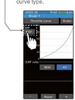
EXP curve screen
Curve type which operates the throttle from the neutral point to the high point on a curved curve.

VTR curve screen
Curve type which sets the switching point between the throttle neutral point and high point and operates the throttle on a linear curve.
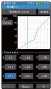
Curve screen
Curve type which sets 9 points between the throttle neutral point and high point and operates the throttle.



Adjustment method for EXP curve
(Preparation)
-Tap the curve type and select [EXP].
1 Tap the value button of the [EXP rate] Value input buttons appear on the screen. When you want to quicken Throttle operation, use the [+] button to adjust the + side. When you want to make Throttle operation milder, use the [-] button to adjust the - side. If you tap "Quick" or "Mild" when the value is other than "0", Quick / Mild is reversed.

Adjustment buttons
- Adjust with the [+] and [-] buttons.
- Return to the initial value by tapping the [reset] buttons.
Curve rate
-100\~+100
Initial value: 0
* The vertical cursor line moves in conjunction with the operation of the throttle trigger.
2 When finished, return to the Racing menu screen by pressing the HOME button twice.
Throttle VTR adjustment
(Preparation)
-Tap the curve type and select [VTR].
1 Tap the value button of the [VTR rate] Value input buttons appear on the screen. When you want to quicken throttle operation, use the [+] button to adjust the + side. When you want to make throttle operation milder, use the [-] button to adjust the - side. If you tap "Quick" or "Mild" when the value is other than "0", Quick / Mild is reversed.
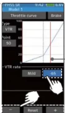
Adjustment buttons
- Adjust with the [+] and [-] buttons.
- Return to the initial value by tapping the [reset] buttons.
Curve rate
-100\~+100
Initial value: 0
Point
1\~99
Initial value: 50
* The vertical cursor line moves in conjunction with the operation of the throttle trigger.

2 Curve switching point adjustment
Tap the value button of the [Point]. Value input buttons appear on the screen, use the [+] or [-] buttons to move to the point you want to set.
3 When finished, return to the Racing menu screen by pressing the HOME button twice.
Dial / Trim Setting
The throttle EXP, VTR adjustment can be controlled with digital trim DT1 to DT6 or digital dial DL1 etc. with the dial select function. (page 66)
Adjustment method for Curve
(Preparation)
-Tap the curve type and select [Curve].
1 Tap the value button of the [Point rate] (1 to 9). Value input buttons appear on the screen, use the [+] or [-] buttons to move to the point you want to set.

Adjustment buttons
- Adjust with the [+] and [-] buttons.
- Return to the initial value by tapping the [reset] buttons.
Curve rate
+ 0 + 1 0 0
Point
1 9
Initial value :
1: + 1 0 / 2: + 2 0 / 3: + 3 0
4: + 4 0 / 5: + 5 0 / 6: + 6 0
7: + 7 0 / 8: + 8 0 / 9: + 9 0
The vertical cursor line moves in conjunction with the operation of the throttle trigger.
2 When fi nished, return to the Racing menu screen by pressing the HOME button twice.

Screen switching between throttle forward side curve and brake side curve.
You can move directly without returning the throttle (forward side) curve screen and the brake curve screen to the curve screen.

Brake curve
This function makes the throttle brake side direction servo operation quicker or milder. It has no effect on the servo maximum operation amount. For the selection from among three kinds of curves (EXP/VTR/Curve) is also possible. If Ratio is set to 100:0 with the trigger function (page 62), the brake side will not operate. Since the setting method of each curve is the same as the throttle (forward) side curve, please read page 81 to 82.
![graph TD A["Home screen"] --> B["Menu screen"] B --> C["Racing menu screen Curve screen"] C --> D["When brake mixing (page 106) is used, brakes 2 and 3 are displayed."] D --> E["Curve screen"] E --> F["VTR curve screen"] F --> G["Curve type which sets the switching point between the throttle neutral…](/content/2026/07/1443791/images/0112e4abed08b80eaf262a797ba97200cafb7636760749fe31af66020a8f349e.jpg)
Dial / Trim Setting
The brake EXP, VTR adjustment can be controlled with digital trim DT1 to DT6 or digital dial DL1 etc. with the dial select function. (page 66)
Speed
Steering speed
Quick steering operation will cause momentary understeering, loss of speed, or spinning. This function is effective in such cases.
![graph TD A["Understeering Spin Smooth cornering"] --> B["Without "Steering speed""] B --> C["With "Steering speed""]](/content/2026/07/1443791/images/535da905928bba03d0763407af5d3c1305a707f1585c7b9da5c618699c53091d.jpg)
Operation
- This function limits the maximum speed of the steering servo. (Delay function)
- The steering speed when the steering wheel is operated (Turn direction-) and returned (Return direction) can be independently set.
- If the steering wheel is turned slower than the set speed, the steering servo is not affected.
![graph TD A["Open"] --> B["Turn"] B --> C["Return"] C --> D["Turn"] D --> E["Return"] E --> F["Turn"] F --> G["Return"] G --> H["Turn"] H --> I["Return"] I --> J["Turn"] J --> K["Return"]](/content/2026/07/1443791/images/52aea1c7bc004c1b1df25bda420d648ebc8980a3d9c20e5e69b7e9057e9e7f78.jpg)
![graph TD A["Home screen"] --> B["Menu screen"] B --> C["Racing menu screen"] C --> D["Steering speed"] D --> E["Steering speed"] E --> F["Steering speed"] F --> G["Steering speed"] G --> H["Steering speed"] H --> I["Steering speed"] I --> J["Steering speed"] J --> K["Steering speed"] K --> L["Steeri…](/content/2026/07/1443791/images/9dc8847b1a717aaaf3de94333366b4ec485e426cdc6fe1e69dbf34c43b1e9f07.jpg)
Steering Speed adjustment
1 ("Turn" direction delay adjustment)
Tap the value button of the [Turn]. Value input buttons appear on the screen. Use the [+] and [-] buttons to adjust the turn speed amount.


2 ("Return" direction adjustment)
Tap the value button of the [Return]. Value input buttons appear on the screen. Use the [+] and [-] buttons to adjust the return speed amount.


Adjustment buttons
- Adjust with the [+] and [-] buttons.
- Return to the initial value by tapping the [reset] buttons.
Speed range
1\~100
Initial value :
100, there is no delay.

Adjustment buttons
- Adjust with the [+] and [-] buttons.
- Return to the initial value by tapping the [reset] buttons.
Speed range
1\~100
Initial value :
100, there is no delay.

3 When finished, return to the Racing menu screen by pressing the HOME button twice.
Dial / Trim Setting
The steering speed adjustm"Hurn" and "Return" adjustment can be controlled with digital trim DT1 to DT6 or digital dial DL1 etc. with the dial select function. (page 66)
Throttle speed
Sudden throttle trigger operation on a slippery road only causes the wheels to spin and the vehicle cannot accelerate smoothly. Setting the throttle speed function reduces wasteful battery consumption while at the same time permitting smooth, enjoyable operation.
Without "Throttle speed"
Slow start due to skidding

With "Throttle speed"
Quick start without skidding

Operation
-Throttle servo (ESC) operation is delayed so that the drive wheels will not spin even if the throttle trigger is operated more than necessary. This delay function is not performed when the throttle trigger is returned and at brake operation.
-1 speed, 2 speed, or 3 speed can be selected.
![graph TD A["Home screen"] --> B["Menu screen"] B --> C["Racing menu screen"] C --> D["Speed screen"] D --> E["Throttle speed"] E --> F["1 Speed"] F --> G["2 Speed"] G --> H["3 Speed"] style A fill:#f9f,stroke:#333 style B fill:#ccf,stroke:#333 style C fill:#cfc,stroke:#333 style D fill:#fcc,stroke:#…](/content/2026/07/1443791/images/7f3639106b75c1d03f55633ed84672cda0ca6eab245974f6737ef1f2c8eda12f.jpg)

Function
Adjustment method for 1 Speed
(Preparation)
-Tap the speed mode and select [1].
1 ("ALL" turn direction delay adjustment) Tap the [Turn] side of [All] value button. Value input buttons appear on the screen. Use the [+] and [-] buttons to adjust the turn speed amount.

Adjustment buttons
- Adjust with the [+] and [-] buttons.
- Return to the initial value by tapping the [reset] buttons.
Speed range
1\~100
Initial value :
100, there is no delay.

Servo operation is delayed.
* Throttle trigger position
2 ("ALL" return direction delay adjustment)
Tap the [Return] side of [All] value button. A warning is displayed saying "Return speed will be slow. Please be careful.". If you want to use the return, tapped [Close]. Value input
buttons appear on the screen. Use the [+] and [-] buttons to adjust the return speed amount.

Adjustment buttons
- Adjust with the [+] and [-] buttons.
- Return to the initial value by tapping the [reset] buttons.
Speed range
1\~100
Initial value :
100, there is no delay.

Servo operation is delayed.
* Throttle trigger position

3 When finished, return to the Racing menu screen by pressing the HOME button twice.
Adjustment method for 2 Speed
(Preparation)
-Tap the speed mode and select [2].
1 ("Low" and "High" turn direction delay adjustment)
Tap the [Turn] side of [Low] or [High] value button. Value input buttons appear on the screen. Use the [+] and [-] buttons to adjust the turn speed amount.
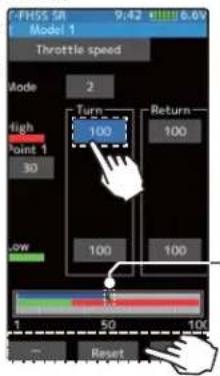
Adjustment buttons
- Adjust with the [+] and [-] buttons.
- Return to the initial value by tapping the [reset] buttons.
Speed range
High :1\~100
Low :1\~100
Initial value
100, there is no delay.
Servo operation is delayed.
* Throttle trigger position
2 ("Low" and "High" return direction delay adjustment)
Tap the [Return] side of [Low] or [High] value button. A warning is displayed saying "Return speed will be slow. Please be careful.". If you want to use the return, tap [Close]. Value input buttons appear on the screen. Use the [+] and [-] buttons to adjust the return speed amount.


Adjustment buttons
- Adjust with the [+] and [-] buttons.
- Return to the initial value by tapping the [reset] buttons.
Speed range
High :1\~100
Low :1\~100
Initial value :
100, there is no delay.

* Throttle trigger position
3 (Speed switching point adjustment)
When you want to change the "Low" and "High" switching point, tap the [point 1] value button. Value input buttons appear on the screen, use the [+] or [-] buttons to move to the point you want to set.
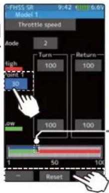
Adjustment buttons
- Adjust with the [+] and [-] buttons.
- Return to the initial value by tapping the [reset] buttons.
Point
Point 1:1\~100
Initial value : 30
* Throttle trigger position
4 When finished, return to the Racing menu screen by pressing the HOME button twice.
Adjustment method for 3 Speed
(Preparation)
-Tap the speed mode and select [3].
1 ("Low", "Middle", or "High" turn direction delay adjustment)
Tap the [Turn] side of [Low] or [High] value button. Value input buttons appear on the screen. Use the [+] and [-] buttons to adjust the turn speed amount.

Adjustment buttons
- Adjust with the [+] and [-] buttons.
- Return to the initial value by tapping the [reset] buttons.
Speed range
High :1\~100
Middle :1\~100
Low :1\~100
Initial value :
100, there is no delay.

Servo operation is delayed.
* Throttle trigger position
2 ("Low", Middle", and "High" return direction delay adjustment)
Tap the [Return] side of [Low], [Middle] or [High] value button. A warning is displayed saying "Return speed will be slow. Please be careful.". If you want to use the return, tap [Close]. Value input buttons appear on the screen. Use the [+] and [-] buttons to adjust the return speed amount.


Adjustment buttons
- Adjust with the [+] and [-] buttons.
- Return to the initial value by tapping the [reset] buttons.
Speed range
High :1\~100
Middle :1\~100
Low :1\~100
Initial value :
100, there is no delay.
* Throttle trigger position
3 (Speed switching point adjustment)
When you want to change the "Low" "Middle" and "High" switching point, tap the [point 1] or [point 2] value button. Value input buttons appear on the screen, use the [+] or [-] buttons to move to the point you want to set.

Adjustment buttons
- Adjust with the [+] and [-] buttons.
- Return to the initial value by tapping the [reset] buttons.
Point
Point 1 :1\~100
Point 2 :1\~100
Initial value point 1:30
Initial value point 2: 60
* Throttle trigger position
4 When finished, return to the Racing menu screen by pressing the HOME button twice.
Dial / Trim Setting
The throttle speed adjustment "Turn" and "Return" adjustment can be controlled with digital trim DT1 to DT6 or digital dial DL1 etc. with the dial select function. (page 66)
Warning
Setting the speed function in the return direction slows the deceleration of the car body, so please be careful to set it carefully.
A.B.S
When the brakes are applied while cornering with a 4-Wheel Drive or other type of vehicle, understeer may occur. The tendency to understeer can be eliminated and corners can be smoothly cleared by using this function.
Operation
- When the brakes are applied, the throttle servo will pulse intermittently. This will have the same effect as pumping the brakes a full size car.
- The brake return amount, pulse cycle, and brake duty can be adjusted.
- By setting the brake mixing function (page 106), it can set for 2nd and 3rd (auxiliary channel) brake.

![graph TD A["Home screen"] --> B["Menu screen Racing menu screen"] B --> C["A.B.S"] C --> D["Throttle curve"] D --> E["Brake"] E --> F["Action control"] F --> G["Engine cat"] G --> H["Line chart"] H --> I["On/OFF"] I --> J["Home screen for a few seconds."] J --> K["It is displayed in the home screen.…](/content/2026/07/1443791/images/24b6bdbd307ef7f52c2a32a9559dc0dd7d92552190f31ce31ced2be876886755.jpg)
- Mode : Function ON/OFF
ABS function ON/OFF setting. using the ABS function, set to "ON".
- Brake return
Sets the rate at which the servo returns versus trigger operation for bra, release. When set to 0%, the AB function is not performed. When to 50%, the servo returns 50% (1/2) of the trigger operation amount and when set to 100%, the servo returns to neutral position.

- Delay
Sets the delay from brake operation to ABS operation. When set to 0%, the ABS function is activated without any delay. At 50%, the ABS function is activated after a delay of approximately 0.7 seconds and at 100%, the ABS function is activated after a delay of approximately 1.4 seconds.
- Cycle speed
Sets the pulse speed (cycle speed). The smaller the set value, the faster the pulse cycle.
- Duty ratio
Sets the proportion of the time the brakes are applied and the time the brakes are released by pulse operation. The ratio can be set to +4 0 -4 in 9 steps.
- Trigger point
Sets the trigger point at which the ABS function begins to operate at brake operation.
When trigger ratio was set to 100:0
When trigger ratio (page 62) was set to 100:0, brake operation stops, and the servo does not operate even if the ABS function is set.
A.B.S. function adjustment
1
(Function ON/OFF)
Tap "Brake" (ON) or (OFF) to select ON / OFF.
"OFF": ABS function OFF
"ON": ABS function ON
When using ABS function ON/OFF by switch, use the switch select function (page 69) to set the switch to be used.

* Displays ON/OFF of the condition that ABS is working by throttle trigger operation.
2
("Brake return" amount adjustment)
Tap the value button of the [Brake return]. Value input buttons appear on the screen. Use the [+] and [-] buttons to adjust the return amount.
"0": No return
"50": Return to the 50% position of the brake operation amount
"100": Return to the neutral position.


Adjustment buttons
- Adjust with the [+] and [-] buttons.
- Return to the initial value by tapping the [reset] buttons.
Return amount
0\~50\~100
Initial value: 50
The amount of brake return varies depending on the curve setting of the brake etc.
3 ("Delay" amount setup)
Tap the value button of the [Delay]. Value input buttons appear on the screen. Use the [+] and [-] buttons to adjust the delay amount.

"0": A.B.S. function performed without any delay
"50": A.B.S. function performed after an approximate 0.5 sec delay.
"100": A.B.S. function performed after an approximate 1.0 sec delay.
4 ("Cycle speed" adjustment)
Tap the value button of the [Cycle speed]. Value input buttons appear on the screen. Use the [+] and [-] buttons to adjust the cycle speed amount.
- The smaller the set value, the faster the pulse speed.


5 ("Duty ratio" setup)
Tap the value button of the [Duty ratio]. Value input buttons appear on the screen. Use the [+] and [-] buttons to adjust the duty ratio amount.
"-4": Brake application time becomes shortest. (Brakes lock with difficulty)
"+4": Brake application time becomes longest (Brakes lock easily)
![graph TD A["Duty ratio"] --> B["Servo travel"] A --> C["Y: (Brake return time)"] A --> D["X: (Brake application time)"] style A fill:#f9f,stroke:#333 style B fill:#ccc,stroke:#333 style C fill:#fff,stroke:#333 style D fill:#fff,stroke:#333](/content/2026/07/1443791/images/5b56c3c53ee474043d5c05717b3e14d4aa9fa1de7145ce8753dcb65a15784999.jpg)

Adjustment buttons
- Adjust with the [+] and [-] buttons.
- Return to the initial value by tapping the [reset] buttons.
Delay amount
0\~100
Initial value: 0
Adjustment buttons
- Adjust with the [+] and [-] buttons.
- Return to the initial value by tapping the [reset] buttons.
Cycle speed amount
1\~100
Initial value: 30
Adjustment buttons
- Adjust with the [+] and [-] buttons.
- Return to the initial value by tapping the [reset] buttons.
Duty ratio amount
-4\~+0\~+4
Initial value: +0
6
("Trigger point" setup)
Tap the value button of the [Trigger point]. Value input buttons appear on the screen. Use the [+] and [-] buttons to adjust the operation point.
- Sets the throttle trigger position at which the A.B.S. function is performed. The number is the % display with the full brake position made 100.
Tap [Normal] or [Reverse] to set the operating range.
"Normal": Neutral to trigger point is the range of motion.
"Reverse": The range from the trigger point to the full brake side is the operating range.
Adjustment buttons
- Adjust with the [+] and [-] buttons.
- Return to the initial value by tapping the [reset] buttons.
Trigger point
5\~95
Initial value: 30


* Throttle trigger position
7
When finished, return to the Racing menu screen by pressing the HOME button.
1/5 scale car and other independent brakes and ABS
ABS can be independently set for the brakes which are controlled by the Brake 2 and Brake 3 (brake 2 and 3 are auxiliary channels). Brake mixing can be set under the mixing menu. (page 106)
Brake 1, 2, 3 can be adjusted independently except the trigger point of the setting item.

Brake mixing Brake 2 "ON"

Brake mixing Brake 3 "ON"
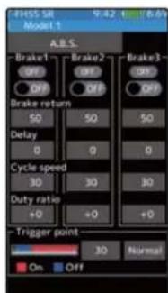
Brake mixing Brake 2&3 "ON"
Switch setting
Use PS1 to PS6 to switch the A.B.S. function ON/OFF.
See the switch select function. (page 69)
Dial / Trim Setting
The brake return amount, delay amount and cycle speed can be controlled with digital trim DT1 to DT6 or digital dial DL1 etc. with the dial select function. (page 66)
Example of A.B.S. function setting when S9373SV used
(There will be a slight difference depending on the state of the linkage.)
Brake return: Approx. 30% (If this value is too high, the braking distance will increase.)
Cycle speed: 5\~7
Duty ratio: 0 (When grip is low: - side, when grip is high: + side)
Delay : 10\~15%
Trigger point: Approx. 70%
Steering mixing: Off
- When the wheels lock, or the car spins, when the brakes are applied fully
Brake return: Increase from 30%
Duty ratio: Shift from 0 to - side (-1, -2, -3, -4)
Delay : Reduce the delay
- When the braking effect is poor and the braking distance is long when the brakes are applied fully
Brake return: Decrease from 30%
Duty ratio: Shift from 0 to + side (+1, +2, +3, +4)
DLY: Increase the delay
Traction control
Trigger operation with cornering on a slippery road surface is hard to get traction and smooth cornering can not be done. By intermittently operating the operation of the throttle, you can smoothly navigate and travel on topological lines. Also, with a drift car, by intermittently operating the motor in the high point direction, a pseudo reverberator engine sound can be reproduced.
Operation
-During throttle operation, the throttle servo is intermittently operated in the forward direction.
- You can set the amount of return to the slow side, the amount of delay, the speed of pumping, the operating point, and the duty ratio of pumping.
-You can choose the action on the slow side near the neutral and the action on the high point side.
![graph TD A["Home screen"] --> B["Menu screen"] B --> C["Racing menu screen"] C --> D["Traction control"] D --> E["Traction control ON/OFF is indicated on the home screen for a few seconds."] E --> F["Home screen: 00:00.00"] F --> G["Menu screen: System menu, Model menu, Linkages menu, Racing menu, M…](/content/2026/07/1443791/images/f444ef01582c01188e06b9776fcde6cf5bbd58eb22df64fa87245a731ef1617d.jpg)
- Mode : Function ON/OFF
Traction control function ON/OFF setting. When using the Traction control function, set to "ON".
- Throttle return
Set the ratio at which the servo returns to the slow side with re to the trigger operation. If set to 0%, the traction control function will not work. At 50%, it returns to the net tral position at 50% (half), 100% of the trigger operation amount.
![graph TD A["Duty ratio: X and Y ratio"] --> B["X: (Throttle application time)"] B --> C["Trigger point"] C --> D["Throttle return"] D --> E["Cycle speed"] E --> F["Trigger operation"] F --> G["Sensor travel"] style A fill:#f9f,stroke:#333 style B fill:#ccf,stroke:#333 style C fill:#cfc,stroke:#333 s…](/content/2026/07/1443791/images/fbaef3c68b5cd4a3e8b902a4d7a38e144c049c50f0521dadd5f354796eb70c74.jpg)
Traction control
- Delay
Set the delay from when the throttle is operated until when the traction control operation starts. When set to 0%, the traction control function works without delay. At 50%, the traction control function works approximately 0.5 second later, and the traction control function works about 1.0 second later at 100%.
- Cycle speed
Sets the pulse speed (cycle speed). The smaller the set value, the faster the pulse cycle.
- Duty ratio
Set the ratio of the time to operate to the high side and the time to operate to the slow side in the pumping operation.
The ratio can be set to +4 \~ +0 \~ -4 in 9 steps.
- Trigger point
In the throttle operation, set the position of the trigger at which traction control starts to work. Normal / Reverse, reverse the throttle operation range where the traction control operates, with the trigger point as the boundary.
Traction control function adjustment
1 (Function ON/OFF)
Tap "Mixing" (ON) or (OFF) to select ON / OFF.
"OFF": Traction control function OFF
"ON": Traction control function ON
When using traction control function ON/OFF by switch, use the switch select function (page 69) to set the switch to be used.

Displays ON/OFF of the condition that traction control is working by throttle trigger operation.
2 ("Throttle return" amount adjustment)
Tap the value button of the [Brake return]. Value input buttons appear on the screen. Use the [+] and [-] buttons to adjust the return amount.
| "0" | :No | return |
| "50" | :Return to the 50% position of the brake operation amount | |
| "100" | :Return to the neutral position. | |
Adjustment buttons
- Adjust with the [+] and [-] buttons.
- Return to the initial value by tapping the [reset] buttons.
Return amount
0\~50\~100
Initial value: 50


The amount of throttle return varies depending on the curve setting of the throttle etc.
3 ("Delay" amount setup)
Tap the value button of the [Delay]. Value input buttons appear on the screen. Use the [+] and [-] buttons to adjust the delay amount.

"0": Function performed without any delay
"50": Function performed after an approximate 0.5 sec delay.
"100": Function performed after an approximate 1.0 sec delay.
4 ("Cycle speed" adjustment)
Tap the value button of the [Cycle speed]. Value input buttons appear on the screen. Use the [+] and [-] buttons to adjust the cycle speed amount.
- The smaller the set value, the faster the pulse speed.
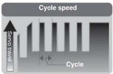

5 ("Duty ratio" setup)
Tap the value button of the [Duty ratio]. Value input buttons appear on the screen. Use the [+] and [-] buttons to adjust the duty ratio amount.
"-4": Brake application time becomes shortest. (Brakes lock with difficulty)
"+4": Brake application time becomes longest (Brakes lock easily)
![graph TD A["Duty ratio"] --> B["Servo travel"] A --> C["Y: (Brake return time)"] A --> D["X: (Brake application time)"] style A fill:#f9f,stroke:#333 style B fill:#ccc,stroke:#333 style C fill:#fff,stroke:#333 style D fill:#fff,stroke:#333](/content/2026/07/1443791/images/38615c7220d6db2b1bc8d26b0594871506140f8cbdaeb9a9cdce816a52f7f50c.jpg)

Adjustment buttons
- Adjust with the [+] and [-] buttons.
- Return to the initial value by tapping the [reset] buttons.
Delay amount
0\~100
Initial value: 0
Adjustment buttons
- Adjust with the [+] and [-] buttons.
- Return to the initial value by tapping the [reset] buttons.
Cycle speed amount
1\~100
Initial value: 30
Adjustment buttons
- Adjust with the [+] and [-] buttons.
- Return to the initial value by tapping the [reset] buttons.
Duty ratio amount
-4\~+0\~+4
Initial value: +0

6 ("Trigger point" setup)
Tap the value button of the [Trigger point]. Value input buttons appear on the screen. Use the [+] and [-] buttons to adjust the operation point.
- Sets the throttle trigger position at which the traction control function is performed. The number is the % display with the full brake position made 100.
Tap [Normal] or [Reverse] to set the operating range.
"Normal": High range from the trigger point to the operating range. "Reverse": Operating range from neutral to trigger point.
Adjustment buttons
- Adjust with the [+] and [-] buttons.
- Return to the initial value by tapping the [reset] buttons.
Trigger point
5\~95
Initial value: 30
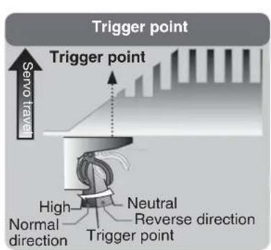

* Throttle trigger position
7 When finished, return to the Racing menu screen by pressing the HOME button.
Switch setting
Use PS1 to PS6 to switch the traction control function ON/OFF. See the switch select function. (page 69)
Dial / Trim Setting
The throttle return amount, delay amount and cycle speed can be controlled with digital trim DT1 to DT6 or digital dial DL1 etc. with the dial select function. (page 66)
Start
If the track is slippery and you begin to accelerate by pushing the trigger to full throttle, the car wheels will spin and the car will not accelerate smoothly. When the Start function is activated, merely operating the throttle trigger slowly causes the throttle servo to automatically switch from the set throttle position to a preset point so that the tires do not lose their grip and the car accelerates smoothly.
Without "Throttle speed"
Slow start due to skidding

With "Throttle speed"
Quick start without skidding

Operation
- When the throttle trigger is moved to the preset position (trigger point), the throttle servo moves to the preset position.
- When the throttle trigger is operated slowly so that the wheels will not spin, the car automatically accelerates to the set speed.
- This function is effective only for the first throttle trigger operation at starting. This function has to be activated before every start.
- When the throttle trigger is returned slightly, the Start function is automatically deactivated and the set returns to normal throttle trigger operation.
![graph TD A["Home screen"] --> B["Menu screen"] B --> C["Racing menu screen"] C --> D["Start"] D --> E["Start Button"] E --> F["User Interface"] F --> A style A fill:#f9f,stroke:#333 style B fill:#ccf,stroke:#333 style C fill:#cfc,stroke:#333 style D fill:#fcc,stroke:#333 style E fill:#cff,stroke:#33…](/content/2026/07/1443791/images/012e4672f04dedd5f7155694c44485dcde86066b0bc7a6478e7e34ea87a87487.jpg)
Start function adjustment
1 (Function ON/OFF)
Tap "Mode" (ON) or (OFF) to select ON / OFF.
"OFF": Start function OFF
"ON": Start function ON
The status display changes to [Ready].
To enable the [Ready] status with the switch, set the "Start switch" with the switch select function (page 69).

Setting
- Tap (ON) / (OFF).
* The status display changes to "Ready".
2 ("Trigger point" setup)
Tap the value button of the [Trigger point] Value input buttons appear on the screen. Use the [+] and [-] buttons to adjust the operation point.

3 ("Preset position" setup)
Tap the value button of the [Preset]. Value input buttons appear on the screen. Use the [+] and [-] buttons to set the preset position of the throttle servo.

Adjustment buttons
- Adjust with the [+] and [-] buttons.
- Return to the initial value by tapping the [reset] buttons.
Trigger point
5\~95
Initial value: 30
Adjust button
Adjust with the [+] and [-] buttons.
- Return to the initial value by tapping the [reset] buttons.
Preset position
0\~100
Initial value: 0
4 ("Ready" setting)
To set "Ready" again, Tap [OFF] of "Status", the display will change to [Ready] and wait for trigger operation. In addition, you can set the switch to be in the [Ready] state in the switch select function (page 69).

Restart
Tap [OFF] to [Ready]
5 When finished, return to the Racing menu screen by pressing the HOME button.
In the [Ready] state, if the throttle trigger is operated to the position of the trigger position, the throttle servo moves to the servo operation position set with preset. It is canceled when the throttle trigger is returned.
Engine cut
When the switch is pressed, the throttle servo will move to the preset position without regard to the throttle trigger position. This is convenient when used to cut the engine of boats, etc. (The switch select function. See page 69)
![graph TD A["Home screen"] --> B["Menu screen Racing menu screen"] B --> C["Engine cut"] C --> D["Engine cut ON/OFF is indicated on the home screen for a few seconds."] D --> E["Engine cut ON/OFF is indicated on the home screen for a few seconds."] E --> F["Engine cut ON/Off is indicated on the home…](/content/2026/07/1443791/images/b22cb6474e90fc34cfd9217097f6aa520c5bac920261273e6c99789038656ba1.jpg)
When trigger ratio was set to 100:0
When trigger ratio (page 62) is set to 100:0, the brake side function will not operate. The preset position set here is the linkage reference. Set the linkage so that the carburetor is fully closed in the preset adjustment range and the engine stops. Full throttle position is set by "advance" of the end point function. Adjust the idling position with throttle trim.
Engine Cut function adjustment
(Preparation)
- Use the switch select function to the "Switch select". (page 69)
When the switch is not set "A switch is not assigned" is displayed. Tap [Switch select] to display the switch selection screen and set the switch.

Engine cut
1 (Preset position setup)
Tap the value button of the [Preset]. Value input buttons appear on the screen. Use the [+] and [-] buttons to set the preset position of the throttle servo.
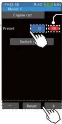
*Shows the ON/OFF state
Adjust button
Adjust with the [+] and [-] buttons.
- Return to the initial value by tapping the [reset] buttons.
Preset position
0\~100
Initial value: 0
2 When finished, return to the Linkage menu screen by pressing the HOME button.
Dial / Trim Setting
The function select dial function can control the engine cut preset position with digital dial or digital trim (page 66).
The throttle servo operating position (preset position) set by this setting is unrelated to the setting of other functions. Maximum to minimum servo travel can be set. However, the reverse function setting is enabled.
Caution
①Always operate carefully before using this function.
When push switch PS1 to PS6, or trigger switch TS with preset function set is in the ON state, the servo (motor controller) is locked in the preset position and does not operate even if the throttle trigger is operated. If the servo was operated at the wrong setting, you may lose control of the car (boat).
Steering Mixing
This mixing function uses 2 servos to individually control the left and right steering. Left and right steering can be set independently so smooth cornering is possible. By using the "Steering mixing rate" function, the motions of the servos on the left and right sides of the steering can be adjusted at the same time. The right side steering servo or the left side steering servo connects to receiver channel 1 and the other side connects to receiver auxiliary channels. The channel to which the left and right servo connects is not specified. After the left and right servos are adjusted individually, Ackerman can also be adjusted by Ackerman rate. In addition, the left and right steering are operated in the opposite direction by switch. An emergency brake function by steering can also be set.
![graph TD A["Home screen"] --> B["Menu screen"] B --> C["Mixing menu"] C --> D["Steering mixing"] D --> E["Brake On/Off"] E --> F["Engine cut ON/OFF is indicated on the home screen for a few seconds."] F --> G["Warning display"] style A fill:#f9f,stroke:#333 style B fill:#ccf,stroke:#333 style C fill…](/content/2026/07/1443791/images/ba56dcc88e28423141d2849acecfad923572eaa08f7059cbc27f9c0616c662b9.jpg)
The mixing function is assigned to auxiliary channels used by other mixing cannot be used. When the number of channels is insufficient, cancel the other mixing.
Steering mixing adjustment
1 (Function ON/OFF)
Tap "Mixing" (ON) or (OFF) to select ON / OFF.
"OFF": Mixing function OFF
"ON": Mixing function ON
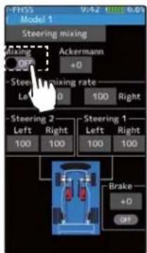
Setting
- Tap (ON) / (OFF).
2 (Channel setup)
The channel list screen used for steering 2 is displayed. Tap the auxiliary channel that connected the servo of steering 2.
- When all channels are in use, a screen saying "No assignable channel" is displayed, please turn off other mixing and select an unused channel. You can check the mixing used on the channel setting screen (page 75).
- T7PX can also be used for steering 2 by setting the throttle to another auxiliary channels setting function and making Ch.2 assignable channel (page 75).


For S-FHSS (analog) system, channels 5, 6 and 7 are displayed.
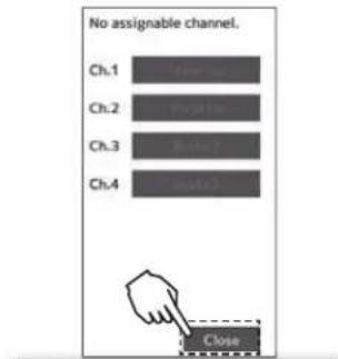
If there is no assignable channel, tap [Close]. Turn off other mixing and make assignable channels.

To set the throttle to another auxiliary channel and use it for steering 2, tap [Yes]. To cancel, [No] is tapped.
3 (Steering 1 servo steering angle adjustment)
Tap the value button of the "Steering 1" [Left] or [Right]. Value input buttons appear on the screen. Turn the steering wheel fully to the left or right and adjust the left and right steering amounts by [+] or [-] button.

Adjustment buttons
- Adjust with the [+] and [-] buttons.
- Return to the initial value by tapping the [reset] buttons.
Steering 1 rate (Left/Right) 0\~140
Initial value : 100
4 (Steering 2 servo steering angle adjustment)
Tap the value button of the "Steering 2" [Left] or [Right]. Value input buttons appear on the screen. Turn the steering wheel fully to the left or right and adjust the left and right steering amounts by [+] or [-] button.
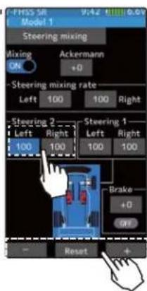
Adjustment buttons
- Adjust with the [+] and [-] buttons.
- Return to the initial value by tapping the [reset] buttons.
Steering 2 rate (Left/Right) 0\~140
Initial value : 100
5 (Steering mixing rate adjustment)
Tap the value button of the "Steering mixing rate" [Left] or [Right]. Value input buttons appear on the screen, adjust each of the left/right steering angles using the [+] or [-] button.
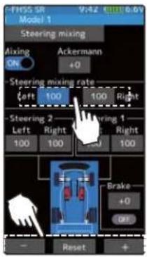
Adjustment buttons
- Adjust with the [+] and [-] buttons.
- Return to the initial value by tapping the [reset] buttons.
Steering mix rate
0\~100
Initial value:100
6 (Ackerman adjustment)
Tap the value button of the "Ackerman rate". Value input buttons appear on the screen, adjust the left and right differential amount and adjust the Ackerman by [+] and [-] button.

Adjustment buttons
- Adjust with the [+] and [-] buttons.
- Return to the initial value by tapping the [reset] buttons.
Steering mix rate
-100\~+0\~+100
Initial value : +0
7 (Steering brake)
(Preparations)
When using this function, set the switch with the "Switch select" function (page 69). Tap the value button of the "Brake rate" Value input buttons appear on the screen, adjust the steering 1/2 operation position by [+] and [-] button.

Adjustment buttons
- Adjust with the [+] and [-] buttons.
- Return to the initial value by tapping the [reset] buttons.
Brake rate
-100\~+0\~+100
Initial value : +0
*Shows the ON/OFF state
8 When finished, return to the Racing menu screen by pressing the HOME button twice.
Dial / Trim Setting
The Ackerman rate adjustment can be controlled with digital trim DT1 to DT6 or digital dial DL1 etc. with the dial select function. (page 66)
Brake Mixing
This function is used when the front and rear brakes must be adjusted independently such as a 1/5 scale GP car. This mixing uses the 2nd channel for the rear brakes and the auxiliary channel for the front brakes, or controls the front brakes with the auxiliary channel servos, or controls the 2nd channel by independent throttle and controls the rear and front brakes with the auxiliary channel. In addition, mixing which varies the auxiliary channels brake rate in proportion to steering operation is also possible.
Operation
-When braking, mixing is applied from brake 1 to brake 2 and brake 3.
-Brake 2 and brake 3 amount, brake 1,2,3 delay, and Brake 2 and brake 3 EXP and ABS can be set.
-Steering mixing which varies front brakes brake 2,3 (auxiliary channels) match the steering operation can be set. Front brake 2,3 (auxiliary channels) can be individually weakened according to the steering left or right operation amount.

When trigger ratio was set to 100:0
When trigger ratio (page 62) was set to 100:0, brake operation stops. When using brake mixing, set the trigger mode to 70:30 or 50:50.
Auxiliary channels A.B.S
Brake mixing can also use the A.B.S function (page 90) for 2nd and 3rd brakes. Except for trigger point and steering mixing, it can be set exclusively for 2nd and 3rd brakes side. Even if the A.B.S function on the 1st brake (2nd channel) side is OFF, you can also use the A. B. S function on the 2nd and 3rd brakes side alone. You can set the ON / OFF of the A.B.S (brake 2, 3) function with the switch setting function (page 69).
![graph TD A["Home screen"] --> B["Menu screen"] B --> C["Mixing menu"] C --> D["Brake mixing"] D --> E["Brake 1"] D --> F["Brake 2"] D --> G["Brake 3"] B --> H["Switch menu"] B --> I["Steering mixing"] B --> J["Brake rate"] B --> K["Brake delay"] B --> L["Steering mixing(L)"] B --> M["Steering mixing…](/content/2026/07/1443791/images/fc4316a6f4954b6cc6213b94ff223e7f4cae12365de33d9c4269cd9001ece431.jpg)
Brake mixing ON

Brake mixing Brake 2 "ON"

Brake mixing Brake 3 "ON"

Brake mixing Brake 2&3 "ON"
The mixing function is assigned to auxiliary channels used by other mixing cannot be used. When the number of channels is insufficient, cancel the other mixing.
Steering mixing adjustment
1 (Function ON/OFF)
Tap "Mixing" (ON) or (OFF) to select ON / OFF.
"OFF": Mixing function OFF
"ON": Mixing function ON

Setting
- Tap (ON) / (OFF).
2 (Channel setup)
The channel list screen used for brake 2 or brake 3 is displayed. Tap the auxiliary channel that connected the servo of brake 2 or brake 3.
- When all channels are in use, a screen saying "No assignable channel" is displayed, please turn off other mixing and make an unused channel. You can check the mixing used on the channel setting screen (page 75).
- T7PX can also be used for brake 2 or 3 by setting the steering to another auxiliary channels with the channel setting function and making Ch.1 assignable channel (page 75).
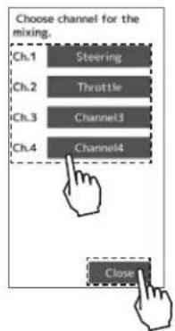
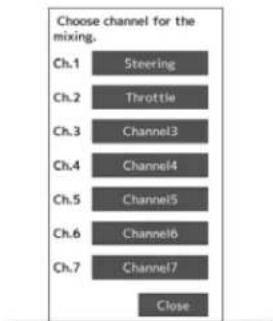
For S-FHSS (analog) system, channels 5, 6 and 7 are displayed.

If there is no assignable channel, tap [Close]. Turn off other mixing and make assignable channels.

To set the steering to another auxiliary channel and use it for brake 2 or 3, tap [Yes]. To cancel, [No] is tapped.
3 (Brake 2 & 3 rate)
Tap the value button of the "Brake 2 or 3" [Brake rate]. Value input buttons appear on the screen, use the [+] and [-] buttons to adjust the brake rate amount.
- When adjusting the brake amount of both brakes after individually adjusting the Brake 2 and Brake 3, select "Brake 2,3 rate".
- The brake 1 rate is linked with throttle channel (ATL) setting.

Adjustment buttons
- Adjust with the [+] and [-] buttons.
- Return to the initial value by tapping the [reset] buttons.
Brake rate
0\~100
Initial value:100
4 (Delay amount setup)
Tap the value button of the "Brake 1 or 2,3" [Brake delay]. Value input buttons appear on the screen, use the [+] and [-] buttons to adjust the delay amount.
- Since a delay at all the brakes is dangerous, a delay is not applied to the brake to be adjusted last. For example, when brakes 1, 2, and 3 are all used, when a delay is applied to brakes 2 and 3, a delay cannot be applied to brake 1. When a delay must be applied to brake 1, the brake 2 or brake 3 delay must be set to "0".
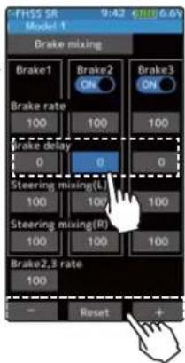
5 (Steering mixing)
Use this function when you want to soften the brakes when steering is operated.
Tap the value button of the "Brake 1 or 2,3" [Left]. Value input buttons appear on the screen. use the [+] and [-] buttons to adjust the brake amount.
Tap the value button of the "Brake 1 or 2,3"[Right]. Value input buttons appear on the screen. use the [+] and [-] buttons to adjust the brake amount. The smaller the value, the weaker the front brakes. Set value "100" is the state in which steering mixing is not performed.
- The mixing amount can be adjusted in a range from 0 to 100.


Adjustment buttons
- Adjust with the [+] and [-] buttons.
- Return to the initial value by tapping the [reset] buttons.
Brake rate (Mixing)
0\~100
Initial value:100
6 When finished, return to the Mixing menu screen by pressing the HOME button twice.
Dial / Trim Setting
The dial select function can control the brake 1,2,3 rate, delay amount and EXP setting using digital dial or digital trim. (page 66)

Gyro Mixing
This function is a remote gain function which adjusts the sensitivity of the Futaba car rate gyro at the T7PX side, and is mixing that uses the auxiliary channels to adjust the gyro sensitivity. When using the T7PX by switching the AVCS and normal modes use PS1-PS6 with the switch select function (page 69).
For a description of the car rate gyro mounting method and handling, refer to the rate gyro instruction manual.
When using SR mode compatible gyro in SR mode channel, set both steering input and gyro sensitivity input channel to SR mode. If either one is in normal mode, gyroscope will not operate properly.
AVCS / NORMAL Modes
The gyro has 2 operating modes: NORMAL mode and AVCS mode. In the AVCS mode, the angle is controlled simultaneously with NORMAL mode rate control (swing speed). The AVCS mode increases straight running stability more than that of the NORMAL mode. Because the feel of operation is different, choose your favorite mode.
![graph TD A["Home screen"] --> B["Menu screen"] B --> C["Mixing menu"] C --> D["Menu-1"] C --> E["Menu-2"] D --> F["Gyro mixing"] E --> F F --> G["Main menu: TV mixing, CPU mixing, Flash mixing, etc."] style A fill:#f9f,stroke:#333 style B fill:#ccf,stroke:#333 style C fill:#cfc,stroke:#333 style D f…](/content/2026/07/1443791/images/476a7ee99125fbba4c72d1f252f1ac354c57012ebeb9a0ff7ed8a1fde83943fd.jpg)
The mixing function is assigned to auxiliary channels used by other mixing cannot be used. When the number of channels is insufficient, cancel the other mixing.

Gyro mixing adjustment
(Preparation)
- Refer to the gyro instruction manual and connect the gyro to the receiver. When using remote gain, connect gyro sensitivity adjustment to the auxiliary channels of the receiver.
- When using gyro mixing by switching between the NORM (normal) and AVCS modes, use the switch select function (page 69) to set the switch to be used.
1 (Function ON/OFF)
Tap "Mixing" (ON) or (OFF) to select ON / OFF.
"OFF": Mixing function OFF
"ON": Mixing function ON

Setting
- Tap (ON) / (OFF).
2 (Channel setup)
The channel list screen used for the gain steering channel is displayed. Tap the auxiliary channel that connected the gain steering channel.
- When all channels are in use, a screen saying "No assignable channel" is displayed, please turn off other mixing and make an unused channel. You can check the mixing used on the channel setting screen (page 75).
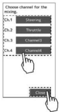

![No assignable channel. Ch.1 Ch.2 Ch.3 Ch.4 Close If there is no assignable channel, tap [Close]. Turn off other mixing and make assignable channels.](/content/2026/07/1443791/images/9f9eb572a9a0fec0c5cac57b64c3c5a9f3e83e39c9e0b37a7bd6cdf36eeaafbb.jpg)
3 (Gyro mixing type selection)
Tap the Gyro type and select [1 gain], [2 gain] or [4 gain].
"1 gain": One mode only
"2 gain": Switching Gyro gain 1 and Gyro gain 2
"4 gain": Set 4 Gyro gains.
2 groups of 2 gains can be set in one group.
Set the switch to change the group and the switch to change the gain in the group. (Use to 2 switch)
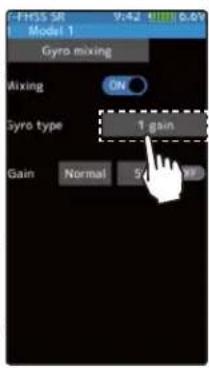
Setting
- Tap Gain type.
1 gain/ 2 gain/ 4 gain

When changing the gain with the switch, indicated on the home screen for a few seconds.
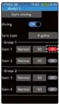

Can be switch between groups 1 and 2 with the group change switch.

* Display the current gyro gain.
4 (Gyro gain adjustment)
Tap the value button of each the [Gain]. Value input buttons appear on the screen, use the [+] and [-] buttons to adjust the brake rate amount.
If you tap "Normal" or "AVCS" when the value is other than "0", Normal / AVCS is changed.
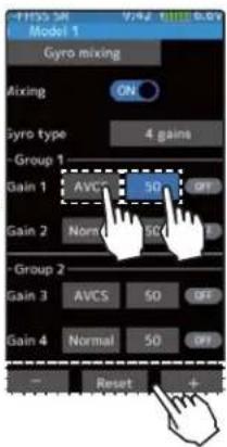
Adjustment buttons
- Adjust with the [+] and [-] buttons.
- Return to the initial value by tapping the [reset] buttons.
Gyro gain
Normal:0\~120
AVCS:0\~120
Initial value: Normal 50
5 When fi nished, return to the Mixing menu screen by pressing the HOME button twice.
Dial / Trim Setting
The gain amount can be adjusted by using the trim dial select function. (page 66)
4WS Mixing
This function can be used with crawlers and other 4WS type vehicles. It is mixing that uses the 1st channel to control front side steering and the auxiliary channel to control rear side steering.
A method of specifying directly for each type of opposite phase (only on the in-phase side), reverse phase, in-phase side and rear side by selecting PS1, PS2, PS4, PS5 and PS6 in the "Switch select" function (page 69). And, it is possible to switch in order.
![graph TD A["Home screen"] --> B["Menu screen"] B --> C["4WS mixing"] C --> D["4WS type 1"] D --> E["4WS mixing"] E --> F["4WS mixing"] F --> G["4WS mixing"] G --> H["4WS mixing"] H --> I["4WS mixing"] I --> J["4WS mixing"] J --> K["4WS mixing"] K --> L["4WS mixing"] L --> M["4WS mixing"] M --> N["4W…](/content/2026/07/1443791/images/359e755ed52178dabea2de3f4fbdb6cdbb670388abdf0b0f81352dbf4b982d66.jpg)
The mixing function is assigned to auxiliary channels used by other mixing cannot be used. When the number of channels is insufficient, cancel the other mixing.
4WS mixing adjustment
(Preparation)
- Since this function is used by switching the type of 4WS with a switch, the switch used by the switch select function (page 69) is set.

(Function ON/OFF)
Tap "Mixing" (ON) or (OFF) to select ON / OFF.
"OFF": Mixing function OFF
"ON": Mixing function ON

Setting
- Tap (ON) / (OFF).
2 (Channel setup)
The channel list screen used for rear steering is displayed. Tap the auxiliary channel that connected the servo of rear steering.
- When all channels are in use, a screen saying "No assignable channel" is displayed, please turn off other mixing and make an unused channel. You can check the mixing used on the channel setting screen (page 75).
- T7PX can also be used for rear steering by setting the throttle to another auxiliary channels setting function and making Ch.2 assignable channel (page 75).
![graph TD A["Ch.1 Steering"] --> B["Ch.2 Throttle"] B --> C["Ch.3 Channel3"] C --> D["Ch.4 Channel4"] D --> E["Close"]](/content/2026/07/1443791/images/2f7dc0b5affd9ce7c943c2e9fb21813f9a82ba3f7a286291ae19361e0b7b56b3.jpg)

For S-FHSS (analog) system, channels 5, 6 and 7 are displayed.

If there is no assignable channel, tap [Close]. Turn off other mixing and make assignable channels.

To set the throttle to another auxiliary channel and use it for steering 2, tap [Yes]. To cancel, [No] is tapped.
3 (4WS type selection)
Tap the 4WS type and select [Type 1], [Type 2], [Type 3] or [Type 4].
"Type 1": Function OFF (front only)
"Type 2": Front side only, reverse phase switching
"Type 3": Front side only, reverse phase and same phase switching
"Type 4" Front side only, reverse phase, same phase, and rear side only switching
Switched in the order shown in the figure below by assigned switch.
Setting
- Tap 4WS type.
Type 1/ Type 2/ Type 3/ Type 4
Type 2
Front side only, Reverse phase switching

Type 3
Front side only, Reverse phase and same phase switching

Type 4
Front side only, reverse phase, same phase, and rear side only switching

4 (Rear side travel adjustment)
Tap the value button of the [Rear mix rate]. Value input buttons appear on the screen, use the [+] and [-] buttons to adjust the rear side travel amount.

Adjustment buttons
- Adjust with the [+] and [-] buttons.
- Return to the initial value by tapping the [reset] buttons.
Rear rate (Rear mix rate)
0\~100
Initial value:100
5 (Mix mode setting)
Tap "MIX mode" (ON) or (OFF) to select ON / OFF.
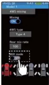
Setting
- Tap (ON) / (OFF).
"OFF": The EXP function of the 1st CH and other settings are not mixed. "ON": The EXP function of the 1st CH and other settings are mixed.
6 When finished, return to the Mixing menu screen by pressing the HOME button twice.
Dial / Trim Setting
The mixing amount can be adjusted by using the trim dial select function. (page 66)
Dual ESC
This function is mixing two ESCs used with crawlers and other 4WD type vehicles and uses the 2nd channel to control the rear motor controller and the auxiliary channel to control the front motor controller.
Front drive only, rear drive only, and both front and rear drive (4WD) switching can be performed by trim dial or by setting a switch for each mode.
Use a 50:50 trigger ratio setting. (page 62).
![graph TD A["Home screen"] --> B["Menu screen"] B --> C["Mixing menu"] C --> D["Dual ESC"] D --> E["Display the current drive mode."] E --> F["Main display screen"] style A fill:#f9f,stroke:#333 style B fill:#ccf,stroke:#333 style C fill:#cfc,stroke:#333 style D fill:#fcc,stroke:#333 style E fill:#cf…](/content/2026/07/1443791/images/91109f8163dbd7c5a9bca483e8c60a37a62991e150e9854e0db6cf6d6f323b2a.jpg)
Dual ESC mixing adjustment
(Preparation)
- This function has 2 methods. One method is used by switching the drive type (4WD/front/rear) by one digital trim/dial. The other method performs switching by assigning a switch to each mode (4WD/front/rear). Both methods are set from among DL1 and DT1 to DT6 by "Trim/Dial select" function.
1 (Function ON/OFF)
Tap "Mixing" (ON) or (OFF) to select ON / OFF.
"OFF": Mixing function OFF
"ON": Mixing function ON
When switching by one digital trim is set, the set switch performs switching as shown below.
Front drive⇔ 4WD ⇔ Rear drive

Setting
- Tap (ON) / (OFF).
2 (Channel setup)
The channel list screen used for the front ESC channel is displayed. Tap the auxiliary channel that connected the front ESC channel.
- When all channels are in use, a screen saying "No assignable channel" is displayed, please turn off other mixing and make an unused channel. You can check the mixing used on the channel setting screen (page 75).
![graph TD A["Choose channel for the mixing."] --> B["Ch.1 Steering"] A --> C["Ch.2 Throttle"] A --> D["Ch.3 Channel3"] A --> E["Ch.4 Channel4"] F["Close"] --> A](/content/2026/07/1443791/images/104c23ccd399b5d7eb43b3ee0d55634ea5f4ed29a431f70e4b6b13adc5862179.jpg)
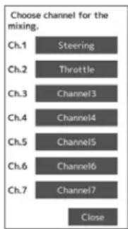
For S-FHSS (analog) system, channels 5, 6 and 7 are displayed.
If there is no assignable channel, tap [Close]. Turn off other mixing and make assignable channels.
3 (Drive ratio adjustment)
Adjust the front and rear motor controller operation amount by or button. The button increases and the button decreases the rear ratio.
Both the front and rear ratios become 100%

Adjustment buttons
- Adjust with the △ and ∇buttons.
- Return to the initial value by tapping the [reset] buttons.
Rear rate (Rear mix rate)
0\~100
Initial value:100
4 (Mix mode setting)
Tap "MIX mode" (ON) or (OFF) to select ON / OFF.
"OFF": The EXP function of the 2nd CH and other settings are not mixed.
"ON": The EXP function of the 2nd CH and other settings are mixed.
5 (Trim mode setup)
Tap "Trim mode" (ON) or (OFF) to select ON / OFF.
"OFF": The trim of the 2nd CH is not mixed.
"ON": The trim of the 2nd CH is mixed.
Setting
- Tap (ON) / (OFF).
Setting
- Tap (ON) / (OFF).
6 When fi nished, return to the Mixing menu screen by pressing the HOME button twice.
Dial / Trim Setting
The trim dial select function can control the drive ratio with digital dial or digital trim. (page 66)
Note:
As this function drives 2 separate motor controllers simultaneously, a mutual load is applied. Use this function carefully so that the motor controllers are not damaged.
Futaba will not be responsible for motor controller, motor, and other vehicle trouble due to use of this function.
CPS Mixing (1, 2, 3)
This function controls the Futaba CPS-1 channel power switch. Normally, when using the CPS-1 unit to light the vehicle dress-up and other illumination (LED) the CPS-1 unit with LED connected is connected to a vacant switch channel and the LEDs are turned on and off by switch while the vehicle is running. However, when the CPS mixing function is used, the LED can be turned on and off and flashed in step with steering and throttle operation, as well as being turned on and off by switch. The flashing speed (cycle) can also be set. For instance, the LED can be flashed as a brake light by throttle brake side operation. Three lines of CPS mixing can be used.
The CPS-1 unit does not operate in SR mode. When using with the T-FHSS SR system, connect it to the channel of the normal mode.
![graph TD A["Home screen"] --> B["Menu screen"] B --> C["Mixing menu"] C --> D["CPS mixing"] D --> E["Toil mixing"] E --> F["Menu-1"] F --> G["Mixing menu"] G --> H["CPS mixing 1 On Off"] H --> I["Home screen 00:00.00"] I --> J["Menu screen"] J --> K["Mixing menu"] K --> L["CPS mixing 2"] L --> M["To…](/content/2026/07/1443791/images/43ac3b001fe4a708e79e1db32505365b1c182f1a94c38f43a4d122340e106db4.jpg)
The mixing function is assigned to auxiliary channels used by other mixing cannot be used. When the number of channels is insufficient, cancel the other mixing.
Dual ESC mixing adjustment
(Preparation)
- CPS-1 unit connects to the receivers auxiliary channel.
- When the LEDs are turned on and off by switch, use the function select switch function (page 69) to set the switch to be used.
- From the CPS Mixing screen, tap [CPS Mixing 1] / [CPS Mixing 2] or [CPS Mixing 3] to display the setting screen.
Setting
- Tap (ON) / (OFF).
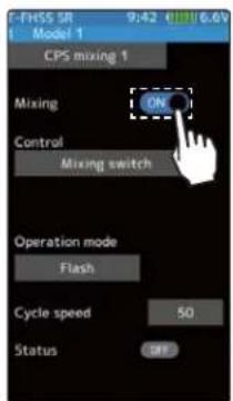
1 (Function ON/OFF)
Tap "Mixing" (ON) or (OFF) to select ON / OFF.
"OFF": Mixing function OFF
"ON": Mixing function ON
2 (Channel setup)
The channel list screen used for the CPS channel is displayed. Tap the auxiliary channel that connected the CPS-1 unit channel.
- When all channels are in use, a screen saying "No assignable channel" is displayed, please turn off other mixing and make an unused channel. You can check the mixing used on the channel setting screen (page 75).
3 (Control system setup)
Tap the [Control]. The mode list appears on the CPS mixing menu screen, and tap from the list and select the control mode. To cancel, tap [Cancel].
"Mixing Switch": ON/OFF by switch set at the CPS mixing
"Steering neutral": ON at steering neutral
"Steering endpoint": ON at both sides of steering
"Throttle neutral": ON at throttle neutral
"Throttle forward": ON at throttle forward side
"Throttle brake": ON at throttle back (brake) side
"Throttle neutral & brake": ON at throttle neutral and back (brake) sides
4 (ON / OFF switching position selection)
Tap the value button of the [ON/OFF point]. Value input buttons appear on the screen. Use the [+] and [-] buttons to adjust the operation point. Since the ON/OFF state is displayed at the right side of the "Status", setting can be confirmed while operating the function to be controlled (for example, throttle).

5 (Operation mode setup)
Tap the [Operation mode]. The mode list appears on the CPS mixing menu screen, and tap from the list and select the Operation mode. To cancel, tap [Cancel].
"ON/OFF": Normal ON/OFF type
"Flash": Flashing display
6 (Flashing cycle setting)
When "Operation mode" is set to "Flash" the "Cycle speed" can be set to preferred setting. Tap the value button of the [Cycle speed]. Value input buttons appear on the screen. Use the [+] and [-] buttons to adjust the cycle speed amount.
Setting
- Tap control mode.

Adjustment buttons
- Adjust with the △ and ▽ buttons.
- Return to the initial value by tapping the [reset] buttons.
ON/OFF position
5\~95
Initial value:50
*Shows the ON/OFF state
Setting
- Tap operation mode.
Adjustment buttons
- Adjust with the [+] and [-] buttons.
- Return to the initial value by tapping the [reset] buttons.
Cycle speed amount 1\~100
Initial value: 50

7 When finished, return to the Mixing menu screen by pressing the HOME button twice.
Tank Mixing
This function is intended for vehicles such as tanks and can be used for the pivotal turn, or the ultra-pivotal brake turn, by steering and throttle operation.
![graph TD A["Home screen"] --> B["Menu screen"] B --> C["Menu-1"] C --> D["Menu-2"] D --> E["Tank mixing"] E --> F["Output: Tank mixing"] subgraph Home screen G["00:00.00"] H["User Interface"] I["User Interface"] J["User Interface"] K["User Interface"] L["User Interface"] M["User Interface"] end subg…](/content/2026/07/1443791/images/bb7a5cd2b9186d6ed194873b9a5e3b2321b9dfdbba90d948e0a46f48f1d2fa7a.jpg)
Connection channel
The channels connecting the left and right motor controllers are as shown in the figure.

Tank mixing adjustment
1 (Function ON/OFF)
Tap "Mixing" (ON) or (OFF) to select ON / OFF.
"OFF": Mixing function OFF
"ON": Mixing function ON

Setting
- Tap (ON) / (OFF).
2 (Limit ON / OFF)
It is a function to limit the maximum operation amount of the steering and throttle channel so that it does not exceed the limit by the influence of the mixing amount.
Tap "Limit" (ON) or (OFF) to select ON / OFF.
"OFF": Limit function OFF
"ON": Limit function ON
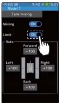
Setting
- Tap (ON) / (OFF).
3 (Forward / backward rate adjustment)
Tap the value button of the [Forward] or [Back]. Value input buttons appear on the screen. Use the [+] and [-] buttons to adjust the forward or reverse speed.
- The throttle channel and the steering channel operate in conjunction with each other, and by operating the trigger to the high side, the car body advances at the [Forward] rate. When the trigger is operated to the brake side, it operates at the [Back] rate.

Adjustment buttons
- Adjust with the [+] and [-] buttons.
- Return to the initial value by tapping the [reset] buttons.
Forward / backward rate
-100\~+100
Initial value: +100
4 (Left / Right side travel adjust)
Tap the value button of the [Left] or [Right]. Value input buttons appear on the screen. Use the [+] and [-] buttons to adjust the left or right side travel amount.
- When the throttle channel and the steering channel work in conjunction, when operating the steering wheel to the right, the car body turns to the right at the [Right] rate the pivotal turn. If you operate to the left, the car will turn to the left at the [Left] rate the pivotal turn.
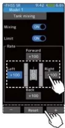
Adjustment buttons
- Adjust with the [+] and [-] buttons.
- Return to the initial value by tapping the [reset] buttons.
Left / Right travel
-100\~+100
Initial value: +100

Function
5 When finished, return to the Mixing menu screen by pressing the HOME button twice.
When steering and trigger are operated at the same time.
If you manipulate the trigger to the high side and operate the steering wheel to the right, the body will turn right at the rate of [forward], [right].
If you manipulate the trigger to the high side and operate the steering wheel to the left, the body turns to the left at the rate of [forward], [left].
Operating the steering wheel while operating the trigger to the brake side will operate the same as the forward side in the reverse direction.
Program Mixing (1, 2, 3, 4, 5)
These functions allow you to apply mixing between the steering, throttle and auxiliary channel.
Additional Functions
-When the steering or throttle channel is the master channel (channel that applies mixing), trim data can be added. (Trim mode)
- The mixing mode selection. (Master mixing mode)
- The master channel mixing center point (point at which the direction changes) can be offset. (Offset function)
Movement of the slave channel side
The movement of the master channel side will include movement of the slave channel side.
When trigger ratio was set to 100:0
When trigger ratio (page 62) is set to 100:0, brake operation stops. When the m channel is set to throttle, mixing operates only at the "Rate A (forward)" side. It does not operate at the "Rate B (brake)" side.
![graph TD A["Home screen T7PX 00:00.00"] --> B["Menu screen"] B --> C["Menu-1"] C --> D["Menu-2"] D --> E["Program mixing"] E --> F["FHSS SR Model 1"] F --> G["Program mixing 1"] G --> H["Program mixing 2"] H --> I["Program mixing 3"] I --> J["Program mixing 4"] J --> K["Program mixing 5"] K --> L["F…](/content/2026/07/1443791/images/982208d0df6a26a64bee9a1a4bfb7044251ebf86be291da06a47acf8e7b18315.jpg)
On the page 1, the setting screen such as the curve, mixing rate adjustment screen, page 2, mixing ON / OFF etc. is displayed.
Program composite adjustment
(Preparation)
- Use the switch select function (page 69) to select the switch. (as desired)
- From the Program mixing screen Tap [Program mixing 1] - [Program mixing 5] to use to move to the setting screen.
1 (Function ON/OFF)
Tap [1/2] at the upper right of the screen to display page 2.
Tap "Mixing" (ON) or (OFF) to select ON / OFF.
"OFF": Mixing function OFF
"ON": Mixing function ON
2 (Master / Slave channel setup)
Tap the [Master] or [Slave], and the channel setting screen will be displayed. Tap on that channel to select.
To cancel, tap [Close].

3 (Mix mode setting)
Tap "MIX mode" (ON) or (OFF) to select ON / OFF.
"OFF": The EXP function of the 2nd CH and other settings are not mixed.
"ON": The EXP function of the 2nd CH and other settings are mixed.
4 (Trim mode setup)
Tap "Trim mode" (ON) or (OFF) to select ON / OFF.
"OFF": The trim of the 2nd CH is not mixed.
"ON": The trim of the 2nd CH is mixed.
Setting
- Tap (ON) / (OFF).
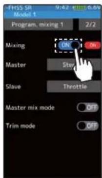
Setting
- Tap channel.

For S-FHSS (analog) system, channels 5, 6 and 7 are displayed.
Setting
- Tap (ON) / (OFF).

5 (Left, Forward or A side mixing amount adjustment)
Tap the value button of the "Rate" [Left], [Forward] or [Rate A]. Value input buttons appear on the screen, adjust each of the left, forward or A steering angles using the [+] or [-] button.
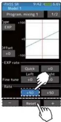
Adjustment buttons
- Adjust with the [+] and [-] buttons.
- Return to the initial value by tapping the [reset] buttons.
Left / Forward / A side rate
-120\~0\~+120
Initial value: +50
6 (Right, brake or B side mixing amount adjustment)
Tap the value button of the "Rate" [Right], [Brake] or [Rate B]. Value input buttons appear on the screen, adjust each of the right, brake, or rate B steering angles using the [+] or [-] button.

Adjustment buttons
- Adjust with the [+] and [-] buttons.
- Return to the initial value by tapping the [reset] buttons.
Right / Brake / B side rate
-120\~0\~+120
Initial value: +50
7 (Curve setting)
"EXP / VTR / Curve" mixing can be set from master channel to slave channel. For details on how to set each curve, please read the steering curve and the throttle curve (pages 78 to 83).
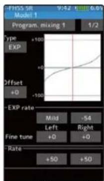
EXP curve VTR curve Curve
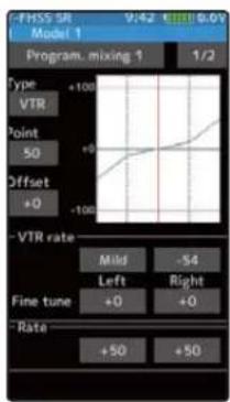

8 When finished, return to the Mixing menu screen by pressing the HOME button twice.
Tilt Mixing
Tilt mixing uses an outboard engine and applies bidirectional mixing from rudder to flap and from flap to rudder so that with a boat, rudder operation and tilt mixing operation can be performed 2 servos.
Tilt mixing can be performed by rudder operation, by steering wheel and flap channel.
Effect of the set value of other functions on tilt mixing
Steering end point function, curve function, speed function, or D/R function setup also effects flap channel operation. However, even if set, steering reverse function setup does not reverse the flap channel.
![graph TD A["Home screen"] --> B["Menu screen"] B --> C["Menu-1"] B --> D["Menu-2"] C --> E["Tilt mixing"] D --> E E --> F["Tilt mixing"] F --> G["Flap to Flap: +100"] F --> H["Flap to Rudder: -100"] G --> I["Mixing"] H --> J["Flip to Flap: +100"] I --> K["Switching menu"] J --> L["Switching menu"] K…](/content/2026/07/1443791/images/a593bb7de1fde4154a0ae718b0747e8c959bc7563f0fac5c5e3e65938bc824cb.jpg)
When the number of channels is insufficient, cancel the other mixing.
Tilt mixing adjustment
(Preparation)
- Use the "Trim / Dial select" function to select the flap channel operation dial. (page 66)
1
(Function ON/OFF)
Tap "Mixing" (ON) or (OFF) to select ON / OFF.
"OFF": Mixing function OFF "ON": Mixing function ON

Setting
- Tap (ON) / (OFF).
2 (Channel setup)
The channel list screen used for the gain steering channel is displayed. Tap the auxiliary channel that connected the gain steering channel.
- When all channels are in use, a screen saying "No assignable channel" is displayed, please turn off other mixing and make an unused channel. You can check the mixing used on the channel setting screen (page 75).
![graph TD A["Choose channel for the mixing."] --> B["Ch.1 Steering"] A --> C["Ch.2 Throttle"] A --> D["Ch.3 Channel3"] A --> E["Ch.4 Channel4"] F["Close"] --> A](/content/2026/07/1443791/images/315d30ea5647c3ef93ac6f2f385e44da3fbc6902763aec4662ca8b75efe29988.jpg)

For S-FHSS (analog) system, channels 5, 6 and 7 are displayed.

If there is no assignable channel, tap [Close]. Turn off other mixing and make assignable channels.
3 (Flap rate check and adjustment)
Tap the value button of the "Flap", value input buttons appear on the screen, and use the [+] and [-] buttons to adjust the fl aps rate amount.
4 (Rudder to Flap mixing amount adjustment)
Tap the value button of the "Rudder to Flap", Value input buttons appear on the screen, and use the [+] and [-] buttons to adjust the mixing amount.
"+" :Operate in same direction as steering
"-":Operate in opposite direction of steering
5 (Flap to Rudder mixing amount adjustment)
Tap the value button of the "Flap to Rudder", Value input buttons appear on the screen, and use the [+] and [-] buttons to adjust the mixing amount.
"+" :Operate in same direction as auxiliary channel
"-":Operate in opposite direction of auxiliary channel
Adjustment buttons
- Adjust with the [+] and [-] buttons.
- Return to the initial value by tapping the [reset] buttons.
Mixing amount (Rudder to Flap)
-100\~+0\~+100
Initial value: +100
Mixing amount (Flap to Rudder)
-100\~+0\~+100
Initial value: -100

6 When fi nished, return to the Mixing menu screen by pressing the HOME button twice.
Dial / Trim Setting
The mixing rate amount can be controlled with digital dial or digital trim, using the trim dial select function. (page 66)
Timer
Allows you to select between one of four timers. Up timer, fuel down timer, lap timer and lap navigate timer.
Up timer function
- The Up timer can be used to count the time between start and stop, etc.
- The timer repeatedly starts and stops each time the switch is operated and accumulates the time between each start and the count reaches 99 minutes 59 seconds, it returns to 00 minutes 00 seconds and repeats the count.)
- The first start operation can be linked to the throttle trigger.
- An alarm sound can be set. The passage of time is announced of a buzzer (beeps) each minute after starting.
- Alarm : Generates a beep at the set time (minutes).
- Pre-alarm : Alarm advance announcement sound. Sounding begins 10 seconds before the set alarm time.
- After starting, the timer is enabled and can be stopped by switch even when the display switches to another screen.

Fuel down timer function
- The Up timer can be used to count the time between start and stop, etc.
- The timer repeatedly starts and stops each time the switch is operated and accumulates the time between each start and st the count reaches 99 minutes 59 seconds, it returns to 00 minutes 00 seconds and repeats the count.)
- The first start operation can be linked to the throttle trigger.
- An alarm sound can be set. The passage of time is announced of a buzzer (beeps) each minute after starting.
- Alarm : Generates a beep at the set time (minutes).
- Pre-alarm : Alarm advance announcement sound. Sounding begins 10 seconds before the set alarm time.
- After starting, the timer is enabled and can be stopped by switch even when the display switches to another screen.

Lap timer function
- The Lap timer can memorize each lap time of each switch operation. (80 laps)
- The race time can be set. Switch operation after the alarm has elapsed automatically stops the timer. Pre-alarm can also be set. The passage of time is announced by sounding of a buzzer (beeps) each minute after starting.
-Alarm :Generates a beep at the set time.
Pre-alarm :Starts sounding the set time (second) before the alarm. (beeps)
- The first start operation can be linked with the throttle trigger.

(Lap timer operation)
- When lap timer is selected, the number of laps (L ap) and the and current lap time are displayed on the setup screen.
* LAP: Counted up each time the switch is pressed after starting. After the switch was pressed, the lap time display pause for 3 seconds. To prevent erroneous counting, switch operation is not accepted during this time.
* Lap memory: The lamp memory saves the lap times of 80 laps.
* The lap time data stored in the lap memory can be checked at the lap list (page 134) screen.
Lap navigate timer function
Lap navigate timer function
- This function sounds a buzzer at a fixed interval after starts. Since only the buzzer can be restarted when the pressed during timer operation, this function can be used as the training run, etc. target time. (Lap navigation alarm) The passage of time is announced by sounding of a buzzer (beeps) every min starting.
- The first start operation can be linked with the throttle trigger.
- The alarm sounds (Alarm/Pre-alarm) can be set separately from the fixed interval buzzer.
- Alarm : Generates a beep at the set time (minutes).
- Pre-alarm : Alarm advance announcement sound. Sounding begins 10 seconds before the set alarm time.
- After starting, the timer is enabled and can be stopped by switch even when the display switches to another screen.
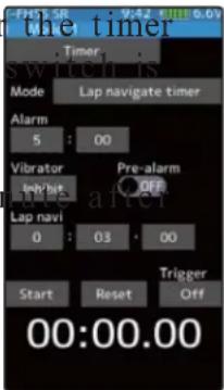
![graph TD A["Home screen"] --> B["Menu screen"] B --> C["Accessory menu screen"] C --> D["Timer"] D --> E["Timer selection"] E --> F["Time display"] F --> G["Minute display (min)\nSecond display (sec)\n1/100 second display"] G --> H["-FHSS SR 9:42 @11:6.0V\nModel 1"] H --> I["Timer"] I --> J["Up time…](/content/2026/07/1443791/images/3df3214e73e08d8efe5853bef041c55f514043e3f10fa13fa2d166712ce3ee9a.jpg)
Racing timer type selection
(Preparation)
Assign the "Timer start" switch using the Switch select function (page 69). When resetting by switch, assign "Timer reset" also.
Setting type
- Tap to select
1 (Racing timer type selection)
Tap the "Mode". The mode list appears on the "Timer" menu screen, and tap the racing timer type.
Up timer
Fuel down timer
Lap timer
Lap navigate timer

2 When fi nished, return to the Accessory menu screen by pressing the HOME button.
Using the Up timer
(Preparation)
Select the "Up timer" from the timer type list and tap.
1 (Alarm time setting)
Tap the value button of the "Alarm time". Value input buttons appear on the screen. Use the [+] and [-] buttons to set the time amount.
Tap [Vibrate] and select the vibration pattern of the alarm from 3 types of patterns and disable (OFF).
(Pre-alarm setting)
Tap (ON) or (OFF) of pre-alarm and select ON / OFF.

Alarm time
OFF, 1\~99 minutes
Initial value: 5 minutes
- Adjust with the [+] and [-] buttons.
- Return to the initial value by tapping the [reset] buttons.
Pre-alarm time
OFF, ON
Initial value: OFF
- Tap (ON) / (OFF).
Grip vibrator type (pattern)
Inhibit(Off), Type 1,2,3
Initial value: Inhibit
- Tap (ON) / (OFF).
2 (Timer start/stop operation)
When the switch (Timer start) assigned by switch select function is pressed, the timer starts. When you press the switch (Timer start) or [Start] / [Reset] on the screen during timer operation, the timer stops.
- Linking only start to the throttle trigger.
Tap [OFF] of the trigger to display [Ready] and wait for the trigger operation. When you operate the trigger to the forward side, the timer starts. Stop is the same as whe switch.

Start / Stop
Status display
3 (Timer reset operation)
With the timer stopped, press the switch (timer reset) set by the Switch setting function, or tap [Reset] on the screen. The timer is reset with the beeping sound.

Timer reset
Using the fuel down timer
(Preparation)
Select the "Fuel down timer" from the timer type list and tap.
1 (Alarm time setting)
Tap the value button of the "Alarm time". Value input buttons appear on the screen. Use the [+] and [-] buttons to set the time amount.
Tap [Vibrate] and select the vibration pattern of the alarm from 3 types of patterns and disable (OFF).
(Pre-alarm setting)
Tap (ON) or (OFF) of pre-alarm and select ON / OFF.

Alarm time
OFF, 1\~99 minutes
Initial value: 5 minutes
- Adjust with the [+] and [-] buttons.
- Return to the initial value by tapping the [reset] buttons.
Pre-alarm time
OFF, ON
Initial value: OFF
- Tap (ON) / (OFF).
Grip vibrator type (pattern)
Inhibit(Off), Type 1,2,3
Initial value: Inhibit
- Tap (ON) / (OFF).
2 (Timer start/stop operation)
When the switch (Timer start) assigned by switch select function is pressed, the timer starts.
When the switch ("Timer start") is pressed while the timer is operating, the timer is reset and simultaneously restarted. (Restart)
When you press the [Reset] on the screen during timer operation, the timer stops.
- Linking only start to the throttle trigger.

Start / Stop
Status display
Tap [OFF] of the trigger to display [Ready] and wait for the trigger operation. When you operate the trigger to the forward side, the timer starts. Stop is the same as when starting with a switch.
3 (Timer reset operation)
With the timer stopped, press the switch (timer reset) set by the Switch setting function, or tap [Reset] on the screen. The timer is reset with the beeping sound.
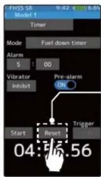
Timer reset
Using the lap timer
(Preparation)
Select the "Lap timer" from the timer type list and tap.
1 (Alarm time setting)
Tap the value button of the "Alarm time". Value input buttons appear on the screen. Use the [+] and [-] buttons to set the time amount.
Tap [Vibrate] and select the vibration pattern of the alarm from 3 types of patterns and disable (OFF).
(Pre-alarm setting)
Tap (ON) or (OFF) of pre-alarm and select ON / OFF.

Alarm time
OFF, 1\~99 minutes
Initial value: 5 minutes
- Adjust with the [+] and [-] buttons.
- Return to the initial value by tapping the [reset] buttons.
Pre-alarm time
OFF, ON
Initial value: OFF
- Tap (ON) / (OFF).
Grip vibrator type (pattern)
Inhibit(Off), Type 1,2,3
Initial value: Inhibit
- Tap (ON) / (OFF).
2 (Timer start operation)
Perform the start and lap count operations with the switch
("Timer start") assigned by function select switch function.
- Linking only start to the throttle trigger
Tap [OFF] of the trigger to display [Ready] and wait for the trigger operation. When you operate the trigger to the forward side, the timer starts. Stop is the same as when starting with a switch.

Start / Stop
Status display

3 (Timer stop and lap reset operation)
When the lap count switch or ("Timer reset") switch is pressed after the time set by "Alarm" has elapsed and the lap time, total time, and average lap time are saved and checked. (Lap list page 134) If the switch ("Timer reset") set by switch setting function is pressed, the timer is reset.
When a switch is not set, tap [Reset] on the screen. The timer is reset with the beeping sound.

Timer reset
Using the lap navigate timer
(Preparation)
Select the "Lap navigate timer" from the timer type list and tap.
1 (Alarm time setting)
Tap the value button of the "Alarm time". Value input buttons appear on the screen. Use the [+] and [-] buttons to set the time amount.
Tap [Vibrate] and select the vibration pattern of the alarm from 3 types of patterns and disable (OFF).
(Pre-alarm setting)
Tap (ON) or (OFF) of pre-alarm and select ON / OFF.
(Lap navigation time setting)
Tap the value button of the "Lap navi". Value input buttons appear on the screen. Use the [+] and [-] buttons to set the time amount.
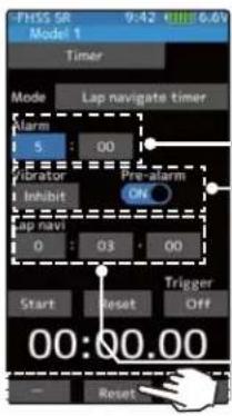
Alarm time
OFF, 1\~99 minutes
Initial value: 5 minutes
- Adjust with the [+] and [-] buttons.
- Return to the initial value by tapping the [reset] buttons.
Pre-alarm time
OFF, ON
Initial value: OFF
- Tap (ON) / (OFF).
Grip vibrator type (pattern)
Inhibit(Off), Type 1,2,3
Initial value: Inhibit
- Tap (ON) / (OFF).
Lap navi time
OFF, 1\~99 seconds
Initial value: 3 seconds
2 (Timer start / navigation restart operation)
When the switch ("Timer start") assigned by switch select function is pressed, the timer starts.
- Linking only start to the throttle trigger
Tap [OFF] of the trigger to display [Ready] and wait for the trigger operation. When you operate the trigger to the forward side, the timer starts. Stop is the same as when starting with a switch.
When your own lap time is less than the target time and the lap counts overlap, the lap navigation alarm timing is too big. The alarm timing can be corrected by pressing the switch ("Timer start") during measurement.
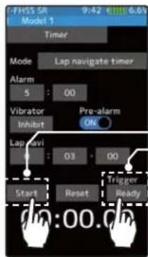
Start / Stop
Status display
3 (Timer stop / reset operation)
Press the switch ("Timer reset") set by the Switch setting function, or tap [Reset] on the screen. The timer stops.
With the timer stopped, press the switch ("Timer reset") set by the Switch setting function, or tap [Reset] on the screen. The timer is reset with the beeping sound.
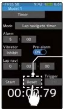
Timer reset
Lap list
Call Lap list when checking the lap memory data (each lap time) memorized by lap timer (page 132) operation.
- After the lap timer is started, the lap time is sequentially memorized at each switch operation.
-The total time and average time are displayed. The faster time is displayed in red characters.
-Lap time data is saved in each model data.
-Up to 80 laps can be saved.
-If the lap timer is reset, the lap list is also cleared.
![graph TD A["Home screen"] --> B["Menu screen"] B --> C["Accessory menu screen"] C --> D["Lap list"] D --> E["Home button setting"] E --> F["User mouse"] F --> A style A fill:#f9f,stroke:#333 style B fill:#ccf,stroke:#333 style C fill:#cfc,stroke:#333 style D fill:#fcc,stroke:#333 style E fill:#cff,s…](/content/2026/07/1443791/images/05f05e0d6ff4d68b841e2656cd6807c6239faaf931df30b3b6dafb691613b6c0.jpg)
Using the lap memory
1 (Lap memory check)
The lap time list displays 40 laps per page and 80 laps maximum on 2 pages. If there is a list on page 2, tap [1/2] / [2/2] at the upper right of the screen to change the display of the page.
2 When finished, return to the Accessory menu screen by pressing the HOME button.
S.BUS Servo
This is a special function which allows Futaba S.BUS/S.BUS2 servo parameter changes to be set by the T7PX transmitter. However, some data changes require a PC and S-Link software. This function is used by connecting Futaba S.BUS/S.BUS2 servo directly to the transmitter. Use the various optional servo extension cords according to the distance between the transmitter and servo. (SR mode setting is for T7PX only, it can not be set with S-Link software.)
-If shutting off while writing the parameters, the servo may fail. Please use this function with sufficient battery power.
-Power is supplied to the servo from the transmitter, but the corresponding voltage is for high voltage servo (HV) use. Since an overvoltage will be applied to servos other than this, connect the corresponding battery to the servo. When the battery is connected, the supply of power from the transmitter automatically stops.

Caution
When connecting an S-BUS servo that does not support high voltage, connect a battery matched to the servo specifications.
High voltage servo support voltage is supplied from the transmitter. If a servo that does not support high voltage is connected, unreasonable force will be applied to the servo and will cause trouble.
Do not disconnect the servo connector or turn off the transmitter power while writing parameters.
It may cause the servo to malfunction.


Function
![graph TD A["Home screen"] --> B["Menu screen"] B --> C["Accessory menu screen"] C --> D["S.Bus servo"] D --> E["User interface"] E --> F["User hand icon"] F --> A style A fill:#f9f,stroke:#333 style B fill:#ccf,stroke:#333 style C fill:#cfc,stroke:#333 style D fill:#fcc,stroke:#333 style E fill:#cff…](/content/2026/07/1443791/images/9bd33cfcf85081ca43e52819ecedb25e8421ffba1dc4d0500e6a300409d420af.jpg)
S.BUS Servo
Using the S.BUS servo function
(Preparation)
- Connect the T7PX and S.BUS or S.BUS2 servo in accordance with the connection diagram shown on page 135.
- Connect the battery to a non-high voltage (HV) support S.BUS/S.BUS2 servo.
1 Turn power on the transmitter. "S.Bus servo" menu is displayed referring to the map of page 135.
2 (S.BUS/S.BUS2 servo read)
Execute this function to read the connected servo type and the data currently set at the servo. Tap the [Read]. The confirmation screen will be displayed. To execute, tap [Yes] to hear an electronic sound and finish setting. To cancel, select [No] and tap it.
-"Reading succeeded" is displayed on the screen and the servo's ID cord and currently set contents are read.
- If "Failed" is displayed on the with the servo is not being performed
-"Reading succeeded" is displayed on the screen and the servo's ID cord and currently set contents are read.
- If "Failed" is displayed on the with the servo is not being performed
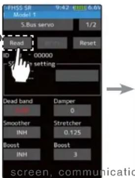

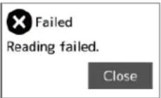
Check the T7PX and servo connection to servo and repeat [Read]. (Connect the battery to a non-high voltage (HV) support servo.)
3 (Writing to S.BUS/S.BUS2)
Execute this function to write the setting data to servo. See pages 138 to 139 for the setting data contents. Tap the [Write]. The confirmation screen will be displayed. To execute, tap [Yes] to hear an electronic sound and finish setting. To cancel, select [No] and tap it.
-"Writing succeeded" is displayed on the screen and the setting data is written to servo.
- If "Failed" is displayed on the screen, communication with the servo is not being performed normally. Check the T7PX and servo connection to servo and repeat [Write]. (Connect the bat
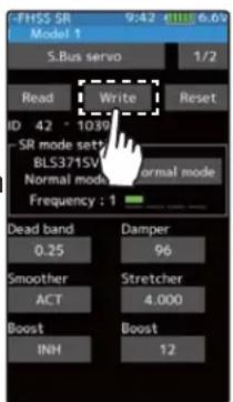

4 (Initialization)
Write the factory set servo setting data to the connected servo. Tap the [Reset]. The confirmation screen will be displayed. To execute, tap [Yes] to hear an electronic sound and finish setting. To cancel, select [No] and tap it.
-"Writing succeeded" is displayed on the screen and the setting data is written to servo.
- If "Failed" is displayed on the screen, communication with the servo is not being performed normally. Check the T7PX and servo connection to servo and repeat "Write". (Connect the battery to a non-high voltage (HV) support servo.)
-"Writing succeeded" is displayed on the screen and the setting data is written to servo. - If "Failed" is displayed on the screen, communication with the servo is not being performed normally. Check the T7PX and servo connection to servo and repeat "Write". (Connect the battery to a non-high voltage (HV) support servo.)
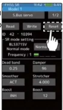


Display data list
1 The type and data of the loaded servo are displayed. Since there are two setting items, change the page as follows.


When the connected servo type is not compatible with the SR mode, "Unsupported Normal mode" is displayed
- Do not plug in or disconnect servos, or connect other servos while keeping the screen where data was read by [Read]. Be sure to connect the servo in the state where [Write] or [Reset] is finished, or press the HOME button to access the accessory menu screen.
- The loaded data can not be written to another servo.
SR mode setting
1 (Writing to servo)
Tap [SR mode] or [Normal mode] of SR mode setting. A confirmation screen of "Notes on SR setting" is displayed, so read carefully and tap [Normal mode] or [SR mode].
- When [Normal mode] is selected, "Writing succeeded" is displayed on the screen, and the setting data is written to the servo.
- If "Failed" is displayed, communication with the servo is not performed normally. Check the connection between the T7PX and the servo, and then execute the write operation again.


2 (When SR mode is selected by writing to servo)
In the confirmation screen of "Notes on SR setting", tap [SR mode], the screen for selecting the SR type is displayed. Three types with different feeling are prepared. (Please repeat the test and choose the type.)


- "Writing succeeded" is displayed on the screen and the setting data is written to the servo. If "Failed" is displayed, communication with the servo is not performed normally. Check the connection between the T7PX and the servo, and then execute the [Write] operation again.
- For the servo set to SR mode, affi x the attached SR label so that the mode can be recognized.
Do not connect any servos that are on SR mode to a receiver via S.BUS/S.BUS2 terminal. You cannot use an SR servo in the SBUS/S.BUS2 ports, as they are not compatible with SR mode. The SR servo can be damaged if it is connected into the S.BUS/S.BUS2 ports.
The type of servo and the set SR type are displayed.
S.BUS function setup
1 On the setting screen of each function, if you tap the item to be set, [-] [reset] [+] will be displayed at the bottom of the screen, tap the [-] [+] on the panel Set. Tap[Reset] to return to the initial value. There are items with no [reset]. In case of selection type, data is switched
by tapping an item.
ID
Displays the ID of the servo whose parameters are to be read. It cannot be changed.
Dead band
The dead band angle at stopping can be specified.
[Relationship between dead band set value and servo operation]
Small - Dead band angle is small and the servo is immediately operated by a small si

Large - Dead band angle is large and the servo does not operate at small signal changes.
(Note) If the dead band angle is too small, the servo will operate continuously and the current consumption will increase and the life of the servo will be shortened.
Damper
The characteristic when the servo is stopped can be set.
When smaller than the standard value, the characteristic becomes an overshoot characteristic. If the value is larger than the standard value, the brake is applied before the stop position.
Especially, when a large load is applied, overshoot, etc. are suppressed by inertia and hunting may occur, depending on the conditions. If hunting (phenomena which causes the servo to oscillate) occurs even though the Dead Band, Stretcher, Boost and other parameters are suitable, adjust this parameter to a value larger than the initial value.
[Relationship between damper set value and servo operation]
Small - When you want to overshoot. Set so that hunting does not occur.
Large - When you want to operate so that braking is not applied. However, it will feel like the servo response has worsened.
(Note) If used in the hunting state, not only will the current consumption increase, but the life of the servo will also be shortened.
Smoother
This function makes servo operation smooth. Set it according to your taste. Normally set it to "ACT". Set it to "INH" when you want especially quick operation. When the smoother function was set to "ACT" and the servo was operated the distance up to the target position is changed in steps so movement is smooth.
Stretcher
The servo hold characteristic can be set. The torque which attempts to return the servo to the target position when the current servo position has deviated from the target position can be adjusted.
This is used when stopping hunting, etc., but the holding characteristic changes as shown below.
[Relationship between stretcher and servo operation]
Small - Servo holding force becomes weaker.
Large - Servo holding force becomes stronger.
(Note) When this parameter is large, the current consumption increases.
Boost/ Boost (ON/OFF)
INH: Boost is ON at the time of low-speed operation. (Normal)
ACT: Boost is always ON. (For quick operation).
The minimum current applied to the internal motor when starting the servo can be set. Since a small travel does not start the motor, it essentially feels like the dead band was expanded. The motor can be immediately started by adjusting the minimum current which can start the motor.
[Relationship between boost set value and servo operation]
Small - Motor reacts to a minute current and operation becomes smooth.
Large - Initial response improves and output torque increases. However, if the torque is too large, operation will become rough.
Channel
This is the S.BUS system channel assigned to the servo. When connected to the receiver S.BUS2 connector as an S.BUS system, the channel used by the transmitter is assigned. When the normal receiver channel is used, channel setting is unnecessary.
Reverse
The direction in which the servo rotates can be changed.
Soft Start
Restricts operation in the specified direction the instant the power is turned on. By using this setting, the first initial movement when the power is turned on slowly moves the servo to the specified position.
Neutral
The neutral position can be changed. When the neutral offset is large value, the servo's range of travel is restricted on one side.
Stop Mode
The state of the servo when the servo input signal is lost can be specified. The "Hold" mode setting holds the servo in its last commanded position even if using AM or FM system.
Speed
Speeds can be matched by specifying the operating speed. The speed of multiple servos can be matched without being affected by motor fluctuations. This is effective for load torques below the maximum torque.
However, note that the maximum speed will not exceed what the servo is capable of even if the servos operating voltage is increased.
Travel [Left] / [Right]
The maximum left and right travels centered about the neutral position can be set independently.
MC (ESC) Link
This is a special function which allows Futaba motor controller (MC) data changes to be set by the T7PX transmitter (MC960CR, MC950CR, MC851C, MC602C, MC402CR, etc.).
However, some data changes require a PC and Link software.
This function is used by connecting ESC directly to the transmitter.
Use the various optional servo extension cords according to the distance between the transmitter and ESC.
-Also connect the battery at the ESC side.

![graph TD A["Home screen"] --> B["Menu screen"] B --> C["Accessory menu screen"] C --> D["MC (ESC) Link"] D --> E["FHSS SR Model 1"] E --> F["Setup item (after it reads)"] F --> G["Read"] F --> H["Write"] F --> I["Reset"] F --> J["Data list"] G --> K["FHSS SR Model 1"] H --> L["Read"] I --> M["Reset"…](/content/2026/07/1443791/images/0d497d07871dfa0de729d1e70a49cca089475b18d77151ac12103fe86b088a65.jpg)
Using the ESC Link function
(Preparation)
-Connect the T7PX and ESC in accordance with the connection diagram shown on page 140.
-Connect the battery to ESC.
1 Turn power on the transmitter. "MC link" menu is displayed referring to the map of page 140. Set the FET amp power switch to the ON position.
2 (ESC read)
Execute this function to read the connected ESC type and the data currently set at the ESC. Tap the [Read]. The confirmation screen will be displayed. To execute, tap [Yes] to hear an electronic sound and finish setting. To cancel, select [No] and tap it.


- "Reading succeeded" is displayed on the screen and the ESC type and currently set contents are read.
- If "Failed" is displayed on the screen, communication with the ESC is not being performed normally. Check the T7PX and ESC connection and the battery connection to ESC and the ESC power switch and repeat [Read].
3 (Writing to ESC)
Execute this function to write the setting data to ESC. See pages 143 to 148 for the setting data contents. Tap the [Write]. The confirmation screen will be displayed. To execute, tap [Yes] to hear an electronic sound and finish setting. To cancel, select [No] and tap it.
- "Writing succeeded" is displayed on the screen and the setting data is written to ESC.
- If "Failed" is displayed on the screen, communication with the ESC is not being performed normally. Check the T7PX and ESC connection and the battery connection to ESC and the ESC power
- Different type ESC data cannot be written. If writing is attempted, "Failed" is displayed on the screen.
4 (Initialization)
Write the factory set ESC setting data to the connected ESC. Tap the [Reset]. The confirmation screen will be displayed. To execute, tap [Yes] to hear an electronic sound and finish setting. To cancel, select [No] and tap it.
- "Writing succeeded" is displayed on the screen and the setting data is written to ESC.
- If "Failed" is displayed on the screen, communication with the ESC is not being performed normally. Check the T7PX and ESC connection and the battery connection to ESC and the ESC power switch and repeat [Write].


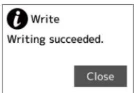

Display data list
-ESC is read referring to the explanation of page 139.
1 Tap the [Data list].
Depending on the ESC type, the setting items are different.
If there are multiple pages, move the page as follows.


![graph LR A["MC(ESC)-Link 1.4"] --> B["MC940/960CR v.17 5000Hz"] B --> C["PWM frequency(max) 3000Hz"] C --> D["PWM frequency(brake) 1500Hz"] D --> E["Read Band IRun"] E --> F["Low battery protection 2.8V"] F --> G["Current limiter INH"] G --> H["Current limit timer Os"] H --> I["Current limiter(time)…](/content/2026/07/1443791/images/fd5fc252554a3af8a968c37dcb53e60832948d76a6ba012cf2ac58e7f0fcd62e.jpg)
![graph LR A["950CR page 1"] --> B["950CR page 2"] B --> C["950CR page 3"] C --> D["To page 1"]](/content/2026/07/1443791/images/4f0ef6185baedd6c63edd30d72aae7bbd71f3e2ba2476a26ba71f30fa4ba3e5b.jpg)
![graph TD A["601CR/850C page 1"] --> B["MC(ESC)-Link"] B --> C["MC(ESC)-Link"] C --> D["MC(ESC)-Link"] D --> E["MC(ESC)-Link"] E --> F["MC(ESC)-Link"] F --> G["MC(ESC)-Link"] G --> H["MC(ESC)-Link"] H --> I["MC(ESC)-Link"] I --> J["MC(ESC)-Link"] J --> K["MC(ESC)-Link"] K --> L["MC(ESC)-Link"] L -->…](/content/2026/07/1443791/images/17d4001ec85ba8c18473f358ff7047ebdeb56da8bc085824fb3276155dcd39d9.jpg)

PWM frequency (min)
MC401,402CR/601,602C/850,851C :0.1kHz(100Hz) 10kHz (10000Hz)
MC950CR :0.5kHz(500Hz) 30kHz(30000Hz)
MC940,960CR :1kHz(1000Hz) 30kHz(30000Hz)
Same as Link software PWM frequency (at Min. load),
MIn sets the "0" PWM frequency at minimum load.
PWM frequency (max)
MC401,402CR/601,602C/850,851C:0.1kHz(100Hz) 10kHz (10000Hz)
MC950CR:0.5kHz(500Hz) 30kHz(30000Hz)
MC940,960CR:1kHz(1000Hz) 30kHz(30000Hz)
Same as Link software PWM frequency (at Max. load).
MAX sets the PWM frequency at maximum load at the output current limit value set by Current Limiter.
PWM frequency (brake)
MC402CR/602C/851C (MC401,601,850 cannot be adjusted 2kHz fi xation)
:Normal(2000Hz) /Hard(1000Hz) /Super hard(500Hz)
MC950CR :0.5kHz(500Hz)30kHz(30000Hz)
MC940,960CR :1kHz(1000Hz)30kHz(30000Hz)
Same as Link software Brake PWM at frequency.
This setting can set the brake PWM frequency.
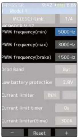
"min" which sets the frequency when the load is small, is set to the high frequency side (large value) when extension is desired after straightaways and curves.
"max" which sets the frequency when the load is large, is set to the high frequency side (large value) when you want to suppress the rise from low speed and when motor heating and commutator roughness are sensed.
When the rise from low speed is poor, and becomes bad even when "max" is set to the low frequency side, use the log data to check if there was a momentary voltage drop. When you want to suppress the overall power, lengthen the run time, and otherwise improve efficiency, set both "max" and "min" to the high frequency side. When you want to set a fixed PWM frequency at full range regardless of the load current, set PWM frequency (at Max. load) and PWM frequency (at Min. load) to the same value.
Dead Band
All type :±2μs\~±50μs
Same as Link software Dead Band.
This sets the range (neutral point range) over which the ESC does not respond to transmitter throttle operation.
The larger the set value, the wider this range.


Low battery protection
MC401,402CR/601,602C/850,851C:2.5V 6.0V
MC950CR/MC940,960CR 2.5V 7.5V
Same as Link software Low Bat Protection.
When the power supply voltage drops, the output current to the motor is limited and supply voltage to the receiver is ensured. When the power supply voltage drops to the set voltage, a protection circuit operation alarm is activated and output to the motor is cut. The protection circuit is automatically reset by recovery of the power supply voltage

Current limiter
MC401,402CR/601,602C/850:50A 300A, INH
MC851C :50A\~300A(can not INH)
MC950CR/MC940,960CR:50A\~500A, INH
Same as Link software PWM frequency (at Max. load).
MAX sets the PWM frequency at maximum load at the output current limit value set by Current Limiter.
Current limiter INH/ACT setting
MC950CR and MC940 / 960CR tap INH OR ACT by tapping the current limiter INH/ACT.
The MC851C does not have an INH (Off) setting
Current limit timer
MC401,402CR/601,602C/850,851C:0sec(OFF)240sec
MC940,960CR:0sec(OFF)\~240sec (MC950CR can not)
Same as Link software Current Limit timer.
The output current can be limited up to the set time lapse from the start of running. This is effective in preventing the motor from outputting wasted energy when the voltage is high immediately after the power battery was recharged.
"Current Limiter (time)" sets the time the output current is limited. This function is disabled when set to "0" sec.
Since the Current Limit Timer starts when the throttle is operated to the forward side and current is output to the motor, this function begins to operate when the motor is run during trim adjustment, etc.


Current limiter (time)
MC401,402CR/601,602C/850,851C :50A\~300A
MC940,960CR :50A\~500A (MC950CR can not)
"Current Limit timer" sets the maximum output current within the time the output current is limited.
Brake max. duty
All type :0%\~100%
Same as Link software Brake Max. Duty.
This setting can set the braking force between the neutral point and Max brake point.
The larger this value, the greater the braking force. When set to "0%", the brakes are not effective.

Reverse max. duty
MC401,402CR/MC950CR/MC940,960CR :0%\~100%
Same as Link software Reverse Max. Duty.
This setting can set the reverse power between the neutral point and Max reverse point.
The larger this value, the greater the reverse power. When set to "0%", reverse is not active.

Neutral brake
All type :0%\~100%
Same as Link software Current Limit timer.
Make this setting when you want to use the brakes at the neutral throttle (OFF) position by
throttle operation. The larger this value, the greater the braking force. When you want to use the neutral brake, set this value to "0%".
Reverse mode shift level
MC401,402CR/MC950CR/MC940,960CR :0%\~100%
Same as Link software Reverse Mode Shift Level.
The reverse operation can be done with the throttle trigger to be thrown from brake status to the neutral. The value can set the amount of the brake in order to switch to the reverse operation.
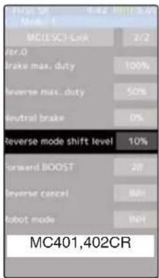
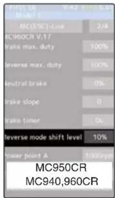
Forward BOOST
MC401,402CR/MC601,602C/MC851C :0%\~100%
Same as Link software Forward Boost (Boost).
Operation near the throttle trigger neutral position becomes a sharp rise.
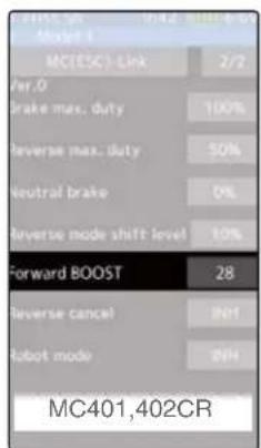

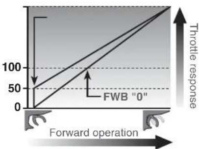
Reverse cancel
MC401,402CR/MC950CR/MC940,960CR :ACT/INH
Same as Link software Reverse Cancel.
When set to "ACT", reverse operation is not performed.
Robot mode
MC401.402CR/MC950CR/
MC940,960CR :ACT/INH
Same as Link software Robot Mode.
When set to "ACT", brake operation is not performed, there is only forward and reverse operation.


Brake slope
MC940,960CR/ :0\~300
Same as Link software Brake Slope.
This function adjusts the braking effect when the throttle was returned (throttle off). It cancels operation like that called engine brake of actual vehicles.
Brake timer
MC940,960CR/MC950CR :0sec\~300sec
Same as Link software Brake Timer.
When the reverse function is used, ordinarily if the trigger is not moved to the brake (reverse) side and then returned from the brake operation position to the neutral position, reverse operation will not be performed. However, when used by intentionally moving the neutral point to the forward side, if brake operation is repeated, reverse operation may be performed even if the trigger is not returned to the neutral position. The time required to switch to reverse operation can be set to prevent this from occurring.was returned (throttle off). It cancels operation like that called engine brake of actual vehicles.

Lead angle
MC950CR/ :0\~1500
Same as Link software Lead Angle.
The lead angle of the motor can be set at the MC950CR side. However, we recommend that it normally be set to "0". Since this setting is premised on setting by referring to the speed log by the Link software.

BEC voltage
MC940,960CR/ :6.0V/7.4V
Same as Link software BEC Volt.
The receiver BEC voltage can be selected from 6.0V and 7.4V. Match the voltage to the rating of the servo connected to the same receiver. This BEC voltage cannot output a voltage higher than the input voltage. For instance, if a 6.0V receiver and servo are used with a power supply voltage of 7.4V or more, set the BEC voltage to 6.0V and when a high voltage receiver and servo are used, set the BEC voltage to 7.4V.

Turbo mode
MC940,960CR/ :Turbo0/Turbo1/Turbo2
Same as Link software Turbo Mode.
This function sets the turbo mode. More power can be displayed by using the turbo mode. Depending on the setting, the motor and ESC may be damaged so make this setting carefully.
(Note) When "Lead angle use" is INH, lead angle setting will not operate even if set to "Turbo1" or "Turbo2". (Turbo mode disabled, Turbo0=Off)
-Turbo0 mode: (No Lead Angle mode) Lead angle - No
When used in races in which the lead angle setting function is inhibited by ESC, set to this mode. The lead angle function is disabled the same as if "Lead angle use" was turned off.
When the lead angle function was disabled by the method described above, the MC940,960CR shows that the lead angle function is off by blinking a blue LED at an ON 0.1 second, OFF 0.9 second cycle at the neutral point.
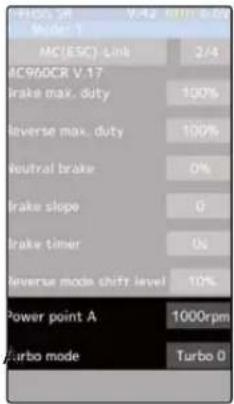
-Turbo1 turbo mode: (Lead Angle mode) Lead angle – Yes
The output can be increased by setting a lead angle.
Depending on the set value, the motor may be damaged so increase the lead angle value in steps from a small value while observing the conditions.
Turn on "Lead angle use" and adjust the lead angle by "Lead angle" and point B, C, D, E (A, B, C, D, E Lead angle) value.
-Turbo2 power mode: (Power Mode) Lead angle – Yes
Displays still more power than a turbo.
However, since even a motor applies a large load on the ESC, make the lead angle larger in steps from a small value while observing the conditions.
Turn on "Lead angle use" and adjust the lead angle by "Lead angle" and point A, B, C, D, E (A, B, C, D, E Lead angle) value.
Power point A
MC940,960CR/ :6.0V/7.4V
Same as Link software Power Point A.
When the turbo mode is power 2 (Power mode) and the lead angle is large, movement may become stiff when entering the course, etc. In this case, make operation smooth by lowering the set speed at power point A.
This function is not performed in modes other than Turbo 2.
Lead angle use
MC940,960CR :ACT/INH
Same as Link software Lead Angle Use.
This function is effective when Turbo Mode is Turbo1 or Turbo2 and sets whether or not lead angle is used. This setting has priority over the Turbo Mode setting. When using in races in which the lead angle function is inhibited by the ESC set this function to INH.
"INH": Lead angle function not used.
"ACT": Lead angle used
Point A,B,C,D,E Lead angle
MC940,960CR :0deg\~59deg
Same as Link software Boost Angle.
Point A,B,C,D,E Rotation
MC940,960CR :0rpm\~120,000rpm

Same as Link software Boost Angle rpm.
When "Lead Angle Use" is turned on the lead angle versus motor speed of the 5 points A to E can be set. The lead angle can be set up to 59 degrees in 1 degree increments.
The "Lead angle" and "Point A, B, C, D, E Lead angle" relationship is shown on the graphs below. Graph [1] shows the relationship when the same value is set at "Points A, B, C, D, E Lead angle" of [1] and [2] and the "Lead angle" was set to "0" and graph [2] shows the relationship when a value other than "0" was set at "Lead angle". As shown in the graphs, [2] is added to the "Points A, B, C, D, E Lead angle" set lead angle and [1] is added to the "Lead angle" set lead angle. For example, if "3" is set at Point A and "Lead angle" of [2] is set to "2", the actual Point A becomes 3+2=5 (deg). Since "Lead angle" of [A] is "0", the actual Point A also becomes 3+0=3 (deg).
Lead Angle(deg)
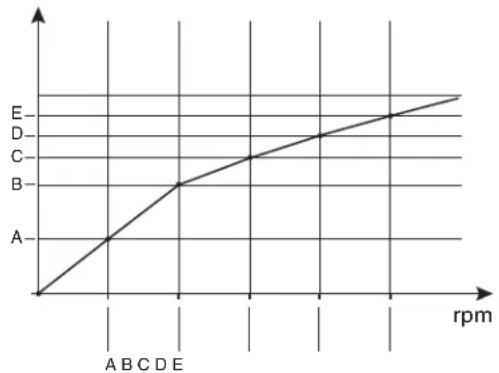
Lead Angle(deg)
2 (Lead angle >"0")

When using in races in which the lead angle setting function is inhibited by the ESC, set "Lead angle use" to "INH". The "Lead angle use" setting has priority over "Turbo mode". If "Lead angle u"s is set to "INH", the lead angle setting function can be turned off even if "Turbo mode" is set to "Turbo 1" or "Turbo 2".
The MC940,960CR shows that the lead angle setting function is "0" OFFing) by blinking a LED.
Roll Out Chart
This function is designed for pan cars. The roll out chart can be calculated from input values for the number of teeth of the spur gear and pinion gear, and the tire diameter, and displayed as a table.
![graph TD A["Home screen"] --> B["Menu screen"] B --> C["Accessory menu screen"] C --> D["Roll out chart"] D --> E["Setup item"] subgraph Setup F["Pinion 30"] --> G["Diameter 50.0"] H["Spur 90"] --> I["Step 0.5"] J["Diameter 57.3"] --> K["Step 57.0"] L["Spur 58.7"] --> M["Step 58.7"] N["Spur 59.3"] -…](/content/2026/07/1443791/images/4d71d4fe6bca1678afea51b3084d2b9c2abff35007e7aa9b3b4030dff895cae1.jpg)
Use of Roll out chart function
1 (Setting of step of the tire diameter input)
Tap the value button of the [Step]. Value input buttons appear on the screen. Use the [+] and [-] buttons to set the step of input numerical value of tire diameter amount.
- The step amount can be set in the range of 0.1 mm to 1.0 mm.

Adjustment buttons
- Adjust with the [+] and [-] buttons.
- Return to the initial value by tapping the [reset] buttons.
2 (Setting of number of teeth of spur gear)
Tap the value button of the [Spur]. Value input buttons appear on the screen. Use the [+] and [-] buttons to set the spur gear. The roll out is then calculated, and the list is updated.
3 (Setting of number of teeth of pinion gear)
Tap the value button of the [Pinion]. Value input buttons appear on the screen. Use the [+] and [-] buttons to set the pinon gear. The roll out is then calculated, and the list is updated.
3 (Setting of tire diameter)
Tap the value button of the [Diameter]. Value input buttons appear on the screen. Use the [+] and [-] buttons to set the tire diameter. The roll out is then calculated, and the list is updated.
4 When fi nished, return to the Accessory menu screen by pressing the HOME button.
Gear Ratio Chart
The Gear Ratio Chart can be calculated from input values for the number of teeth of the spur gear and pinion gear, and secondary gear ratio, and displayed as a table.
![graph TD A["Home screen"] --> B["Menu screen"] B --> C["Accessory menu screen"] C --> D["Gear ratio chart"] D --> E["Setup item\nPinion 2nd Gear ratio\nSpur"]](/content/2026/07/1443791/images/4a6907d3d5dbee2a397aeaac0128a68a04a3593483ee6b09dac9372e897bffe5.jpg)
Use of Roll out chart function
1 (Setting of number of teeth of spur gear)
Tap the value button of the [Spur]. Value input buttons appear on the screen. Use the [+] and [-] buttons to set the spur gear. The roll out is then calculated, and the list is updated.

Adjustment buttons
- Adjust with the [+] and [-] buttons.
- Return to the initial value by tapping the [reset] buttons.
2 (Setting of number of teeth of pinion gear)
Tap the value button of the [Pinion]. Value input buttons appear on the screen. Use the [+] and [-] buttons to set the pinon gear. The roll out is then calculated, and the list is updated.
2 (Setting of number of secondary gear ratio)
Tap the value button of the [2nd gear ratio]. Value input buttons appear on the screen. Use the [+] and [-] buttons to set the 2nd gear ratio. The roll out is then calculated, and the list is updated.
3 When fi nished, return to the Accessory menu screen by pressing the HOME button.
Home Button Setting
You can select the screen to display when you push the HOME button on the Home screen, menu or user menu. You can not change the screen to display by push and holding the HOME button from the menu screen or each function screen.
- Push----Display menu screen or custom menu screen.
- Long press----Trim lock or display the function screen of your choice.
![graph TD A["Home screen"] --> B["Menu screen"] B --> C["Accessory menu screen"] C --> D["Home button setting"] D --> E["Home button setting"] E --> F["Home button setting"] F --> G["Home button setting"] G --> H["Home button setting"] H --> I["Home button setting"] I --> J["Home button setting"] J -…](/content/2026/07/1443791/images/6587989d4be41440bd11d922d6ffb1120e7aa096da246ece446440534ca453b3.jpg)
How to set the Home button
1 (Setting for push)
Tap "Push" [Menu] or [User menu] to select "Menu" / "User menu".
2 (Setting for long press)
Tap "long press".
The function list appears on the Home button setting menu screen. Tap and select the function you want to use. To cancel, tap [Close].
- Since there are multiple pages, tap the mark and move the page.
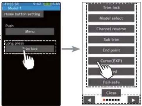
3 When finished, return to the Accessory menu screen by pressing the HOME button.
Telemetry System
With the telemetry system, the running status can be displayed at the transmitter and also recorded as a data log by installing various sensor units to the chassis
(The T-FHSS SR, S-FHSS and FASST systems do not have a telemetry function.)
-The sensor data can be checked at the transmitter by connecting the telemetry sensor sold separately to the S.BUS2 connector of the R334SBS receiver.
-To log this information, a start/stop switch is set by switch setting (page 69).
The log data recorded on a microSD card can be converted to CSV format by the telemetry log converter released at our web page. When copying or moving the log file, always select both .FLI and .FLD files.
-The figure is an example of connection of a telemetry sensor. The data of up to the following 3 types of sensor and the receiver power supply voltage can be transmitted by using the 3-way extension cord or double extension cord sold separately.
The receiver power supply can also be connected to the S.BUS2 connector or channel 1 to 4 connector. A receiver power supply voltage sensor is unnecessary.
![graph TD A["Transmitter"] -->|Signal| B["T-FHSS Receiver"] B --> C["Connect to S.BUS2 Connector"] C --> D["HUB"] D --> E["Switch"] E --> F["Voltage Sensor"] E --> G["Temperature Sensor"] E --> H["RPM Sensor"] E --> I["Futaba"] I --> J["Battery voltage is displayed at the transmitter."] K["Power batt…](/content/2026/07/1443791/images/4fb301310f3501f8989d550bf645061e6d0f04f78dc18892048e4fb1819e643d.jpg)
*Info: Info displayed at the transmitter
Usable sensor options (As of May 2017)
Temperature sensor (SBS-01T) Perfect for engine head, etc.
Temperature sensor (SBS-01TE) Used by attaching to a motor, etc.
RPM Sensor (SBS-01RM) Measures speed over the 0 to 999,900rpm range.
Voltage Sensor (SBS-01V) Measures external power supply voltages up to 100V.
Current sensor (SBS-01C) Measures external power supply voltages up to 70V, capacity and consumption capacity.
GPS sensor (SBS-01/02G) Detect the GPS and measure the position and speed of the car body.
Compatibility with non-Futaba sensors (Castle TL0). (Refer to the sensor instruction manual for more information.)
Telemetry
It is necessary to set telemetry to the on position when setting to TFHSS. Telemetry is not used in TFHSS-SR mode. to use the telemetry function. (page 52) This screen displays and sets the various information from the receiver. An alarm and vibration can be generated depending on the information. The alarm and the vibration are set by each information screen. For example, a drop in the voltage of the receiver battery housed in the model car can be reported by an alarm. The telemetry data received last is memorized. Therefore, even if the receiver power is turned off, information display, audio guide, and alarms remain until the transmitter power is turned off. The speech function can be turned on and off with the specified switch. See the switch select function (page 69).
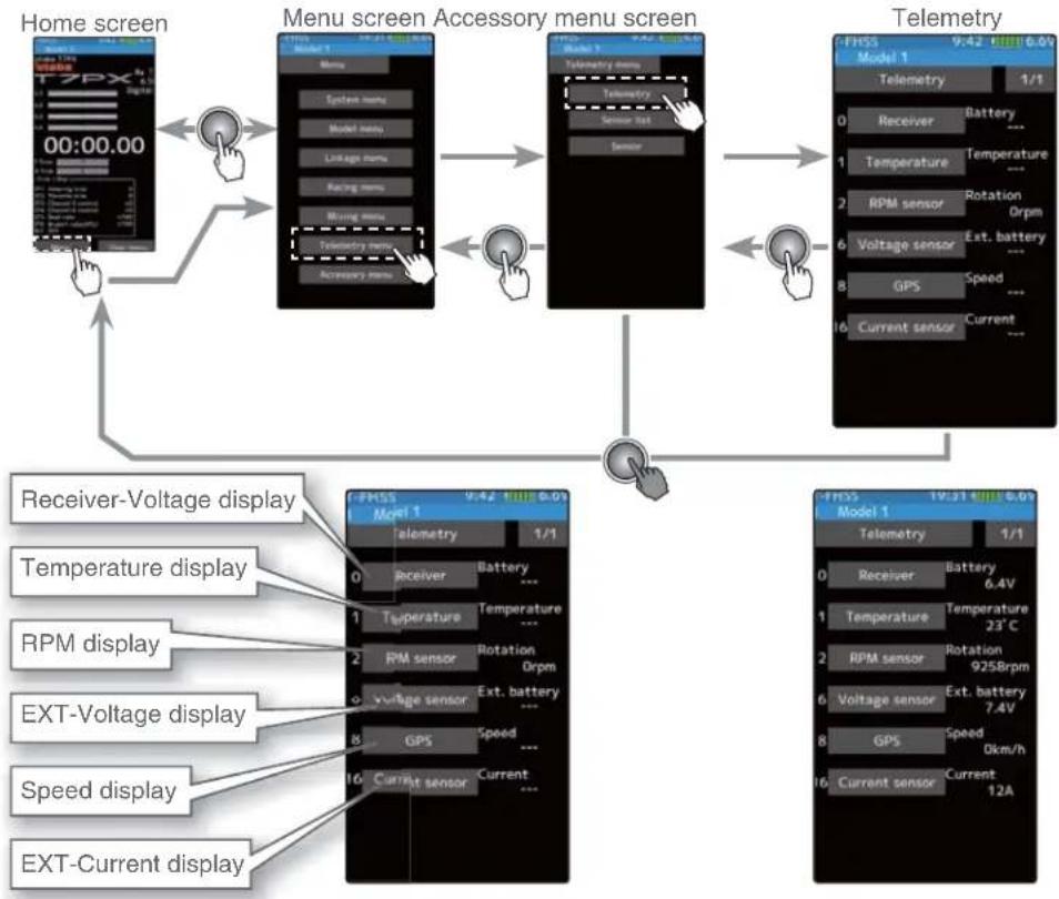
Using Telemetry function
(Preparation)
The sensor used is connected with the receiver referring to the connection diagram of page 152.
1 (Function ON/OFF)
Tap telemetry (ON) or (OFF) to select ON / OFF.
"OFF": Telemetry function OFF
"ON": Telemetry function ON
2 When finished, return to the Linkage menu screen by pressing the HOME button.
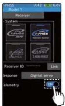
Telemetry function ON
Telemetry: Receiver Battery Voltage
This function displays and sets the receiver power supply battery. The sensor sold separately does not have to be installed. The transmitter initial state voltage is also displayed. For a description of alarm setting when the voltage drops, see the description of the procedure on this page.
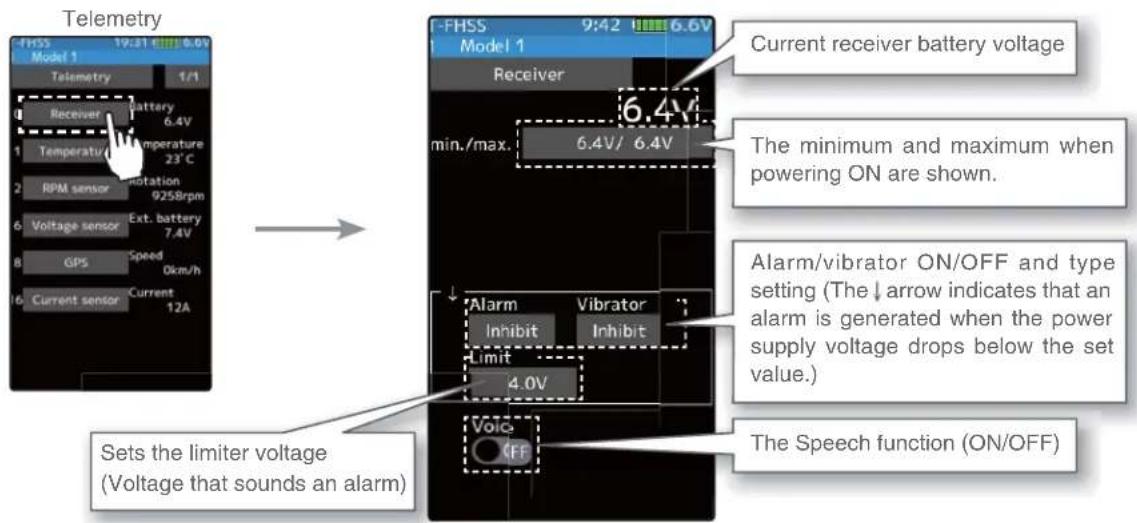
Alarm and Vibrator function setup
1 (Limit adjustment)
Tap the [Limit]. Value input buttons appear on the screen. Use the [+] or [-] button to adjust the limit voltage.
2 (Alarm function setup)
Tap the [Alarm] type and select [Inhibit], [Buzzer] or [Voice].
"Inhibit": No audible alarm
"Buzzer": Audible alarm
"Voice": Voice alarm
3 (Vibrator function setup)
Tap the [Vibrator] type and select [Inhibit], [Type 1], [Type 2], or [Type 3].
"Inhibit": No active vibration
"Type 1": Continuous vibration
"Type 2": Intermittent vibration for a long time
"Type 3": Intermittent vibration for a short time
4 (Speech function setup)
Tap the "Voice" (ON) or (OFF) to select ON / OFF.
"OFF": No voice guide
"ON": Information loaded by voice
Adjustment buttons
- Adjust with the [+] and [-] buttons.
- Return to the initial value by tapping the [reset] buttons.
Setting
- Tap alarm type. Inhibit/ Buzzer/ Voice
Setting
- Tap Vibrator type. Inhibit/ Type 1/ Type 2/ Type 3
Setting
- Tap (ON) / (OFF).
*The voice guide loading interval is set by sensor menu.
5 When fi nished, return to the Telemetry screen by pressing the HOME button.
Telemetry: The Drive Battery Voltage
This function displays and sets the voltage of an external power supply (drive battery, etc.) separately installed in the chassis. Receiver S.BUS 2 connector is used to connect SBS - 01V sensor and battery.
* A drive battery sensor must be installed in the model car. Install and connect the sensor in accordance with the sensor instruction manual.

Alarm and Vibrator function setup
1 (Limit adjustment)
Tap the [Limit]. Value input buttons appear on the screen. Use the [+] or [-] button to adjust the limit voltage.
2 (Alarm function setup)
Tap the [Alarm] type and select [Inhibit], [Buzzer] or [Voice].
"Inhibit": No audible alarm
"Buzzer": Audible alarm
"Voice": Voice alarm
3 (Vibrator function setup)
Tap the [Vibrator] type and select [Inhibit], [Type 1], [Type 2], or [Type 3].
"Inhibit": No active vibration
"Type 1": Continuous vibration
"Type 2": Intermittent vibration for a long time
"Type 3": Intermittent vibration for a short time
4 (Speech function setup)
Tap the "Voice" (ON) or (OFF) to select ON / OFF.
"OFF": No voice guide
"ON": Information loaded by voice
Adjustment buttons
- Adjust with the [+] and [-] buttons.
- Return to the initial value by tapping the [reset] buttons.
Setting
- Tap alarm type. Inhibit/ Buzzer/ Voice
Setting
- Tap Vibrator type. Inhibit/ Type 1/ Type 2/ Type 3
Setting
- Tap (ON) / (OFF).
*The voice guide loading interval is set by sensor menu.
5 When fi nished, return to the Telemetry screen by pressing the HOME button.
Telemetry: RPM
Speed information from an SBS-01RM (telemetry rotation sensor) sold separately is played and set at this screen. The speed of the engine, motor, etc. of the chassis while running can be viewed at the transmitter. When the speed becomes higher (lower) than the set speed, it can be announced by an alarm and vibration.
* A RPM sensor must be installed in the model car. Install and connect the sensor in accordance with the sensor instruction manual.

Alarm and Vibrator function setup
1 (Gear ratio adjustment)
Tap the [Gear ratio]. Value input buttons appear on the screen.
Use the [+] or [-] button to adjust the Gear ratio.
Adjustment buttons
- Adjust with the [+] and [-] buttons.
- Return to the initial value by tapping the [reset] buttons.
2 (Limit adjustment)
Tap the "↑" [Limit] or "↓" [Limit]. Value input buttons appear on the screen.
Use the [+] or [-] button to adjust the limit voltage.
3 (Alarm and vibrator function setup)
Tap the "↑" / "↓" [Alarm] type and select [Inhibit], [Buzzer] or [Voice].
"Inhibit": No audible alarm/ "Buzzer": Audible alarm/ "Voice": Voice alarm
Tap the "↑" / "↓" [Vibrator] type and select [Inhibit], [Type 1], [Type 2], or [Type 3].
"Inhibit": No active vibration
"Type 1": Continuous vibration
"Type 2": Intermittent vibration for a long time
"Type 3": Intermittent vibration for a short time
4 (Speech function setup)
Tap the "Voice" (ON) or (OFF) to select ON / OFF.
"OFF": No voice guide
"ON": Information loaded by voice
*The voice guide loading interval is set by sensor menu.
5 When fi nished, return to the Telemetry screen by pressing the HOME button.
Telemetry: Temperature
This screen displays and sets the temperature information from an SBS-01T (teler temperature sensor) sold separately. The temperature of the engine, motor, amp, etc. of the chassis while running can be viewed at the transmitter. When the temperature becomes higher or lower than the set value, it can be announced by an alarm and vibration.
* A temperature sensor must be installed in the model car. Install and connect the sensor in accordance with the sensor instruction manual.

Alarm and Vibrator function setup
1 (Limit adjustment)
Tap the "↑" [Limit] or "↓" [Limit]. Value input buttons appear on the screen.
Use the [+] or [-] button to adjust the limit voltage.
2 (Alarm and vibrator function setup)
Tap the "↑" / "↓" [Alarm] type and select [Inhibit], [Buzzer] or [Voice].
"Inhibit": No audible alarm/ "Buzzer": Audible alarm/ "Voice": Voice alarm
Tap the "↑" / "↓" [Vibrator] type and select [Inhibit], [Type 1], [Type 2], or [Type 3].
"Inhibit": No active vibration
"Type 1": Continuous vibration
"Type 2": Intermittent vibration for a long time
"Type 3": Intermittent vibration for a short time
3 (Speech function setup)
Tap the "Voice" (ON) or (OFF) to select ON / OFF.
"OFF": No voice guide
"ON": Information loaded by voice
Adjustment buttons
- Adjust with the [+] and [-] buttons.
- Return to the initial value by tapping the [reset] buttons.
Setting
- Tap alarm type. Inhibit/ Buzzer/ Voice
Setting
- Tap Vibrator type. Inhibit/ Type 1/ Type 2/ Type 3
Setting
- Tap (ON) / (OFF).
*The voice guide loading interval is set by sensor menu.
4 When finished, return to the Telemetry screen by pressing the HOME button.
Telemetry: The Drive Battery Electric Current
When the SBS-01C (electric current sensor) sold separately is mounted on the vehicle, the electric current, voltage and consumption capacity of the power battery, etc., can be displayed.
* A drive battery electric current sensor must be installed in the model car. Install and connect the sensor in accordance with the sensor instruction manual.

Current drive battery electric current
The minimum and maximum when powering ON are shown.
Alarm and vibrator ON/OFF and type setting (The ↓ arrow indicates that an alarm is generated when the electric current drops below the set value and the ↑ arrow indicates that an alarm is generated when the electric current exceeds the set value.)
Reset consumption capacity
![graph TD A["Telemetry"] --> B["Current sensor"] B --> C["Setting 12A/12A"] B --> D["Setting 7.4V/7.4V"] B --> E["Capacity 456mAh"] B --> F["Setting 450/450mAh"] A --> G["Telemetry"] G --> H["0 Receiver Battery 6.4V"] G --> I["1 Temperature Temperature 23°C"] G --> J["2 RPM sensor Rotation 925Brpm"]…](/content/2026/07/1443791/images/60dcb4f9558a2aa0a2db8d378cc327fb2c1ec782ffcaaa521406eead9f5cfedc.jpg)

Current drive battery voltage
The minimum and maximum when powering ON are shown.
Alarm and vibrator ON/OFF and type setting (The ↓ arrow indicates that an alarm is generated when the battery voltage drops below the set value and the ↑ arrow indicates that an alarm is generated when the battery voltage exceeds the set value.)
Reset consumption capacity
-Upper side:
Current current / voltage / consumption capacity display.
-Lower:
This is a display of the minimum value / maximum value of the measured current / voltage / consumption capacity after turning on the transmitter power.
* Tap the min / max display button to restart the measurement.


Current drive battery capacity
The minimum and maximum when powering ON are shown.
Alarm and vibrator ON/OFF and type setting (The ↓ arrow indicates that an alarm is generated when the battery capacity drops below the set value and the ↑ arrow indicates that an alarm is generated when the battery capacity exceeds the set value.)
Reset consumption capacity

Function
Alarm and Vibrator function setup
1 (Limit adjustment)
Tap the "↑" [Limit] or "↓" [Limit]. Value input buttons appear on the screen.
Use the [+] or [-] button to adjust the limit voltage.
2 (Alarm and vibrator function setup)
Tap the "↑" / "↓" [Alarm] type and select [Inhibit], [Buzzer] or [Voice].
"Inhibit": No audible alarm/ "Buzzer": Audible alarm/ "Voice": Voice alarm
Tap the "↑" / "↓" [Vibrator] type and select [Inhibit], [Type 1], [Type 2], or [Type 3].
"Inhibit": No active vibration
"Type 1": Continuous vibration
"Type 2": Intermittent vibration for a long time
"Type 3": Intermittent vibration for a short time
3 (Speech function setup)
Tap the "Voice" (ON) or (OFF) to select ON / OFF.
"OFF": No voice guide
"ON": Information loaded by voice
Adjustment buttons
- Adjust with the [+] and [-] buttons.
- Return to the initial value by tapping the [reset] buttons.
Setting
- Tap alarm type.
Inhibit/ Buzzer/ Voice
Setting
- Tap Vibrator type.
Inhibit/ Type 1/ Type 2/ Type 3
Setting
- Tap (ON) / (OFF).
*The voice guide loading interval is set by sensor menu.
4 When finished, return to the Telemetry screen by pressing the HOME button.
Reset consumption capacity display
Unless the reset button of SBS-01C is pressed, the consumption capacity measured by SBS-01C is maintained and displayed as "integrated capacity" on the screen. If you wish to measure the consumption capacity for one run, it is possible to reset the consumption capacity display on the transmitter by the next operation. However, the record of the integrated capacity of the SBS-01C main body cannot be reset by the function which resets the transmitter display.
1 (Reset operation)
Tap the [Reset], the consumption capacity display is reset to "0". The consumption capacity from the time of reset is displayed until you reset it again. If you reset the consumption capacity by pressing the reset button of SBS-01C, the consumption capacity display on the transmitter is also reset.
2 When finished, return to the Telemetry screen by pressing the HOME button.

The reset operation on the transmitter resets the integrated capacity display on the T7PX. It does not reset the integrated capacity on the SBS-01C. The consumption capacity measurement range of SBS-01C is 32767mAh maximum. When this value is exceeded, the consumption capacity display on the transmitter is also reset automatically. Depending on the timing, reset may occur during measurement. Therefore, make sure to reset the integrated capacity on the SBS-01C before the integrated capacity display reaches 32767mAh.
Telemetry: GPS
When SBS-01G/02G (GPS sensor) sold separately is mounted on the car body, you can receive radio waves from GPS satellites and display information on the distance and speed of the car.
* A GPS sensor must be installed in the model car. Install and connect the sensor in accordance with the sensor instruction manual.
* When powered up, the SBS-01/02G begins to acquire GPS satellite data. This process can take several minutes. Please do not move the model during this process. During acquisition, the LED on the SBS-01/02G will blink green; after the satellite's signals have been acquired, the LED will become solid green, and the GPS signal strength display on the transmitter will show three bars.
Moving the model before the satellites are fully acquired will cause a delay in acquiring the satellite signal.
* Since GPS satellites are basically used, accurate distances and speeds may not be displayed depending on the surrounding environment or the conditions of the course.
![graph TD A["Telemetry"] --> B["Distance"] B --> C["The Speech function (ON/OFF)"] C --> D["Speed"] D --> E["The Speech function (ON/OFF)"] E --> F["Time Parameter: Max, Min, Off"] F --> G["Current distance: 9:42 5.6V, 14m, 1000m, 0m"] G --> H["Time Parameter: Max, Min, Off"] H --> I["Time Parameter:…](/content/2026/07/1443791/images/f832b1777cc6f94be39e4a38b6454717b0b5eea28eebf6725f6ca3cee78274ae.jpg)
Alarm and Vibrator function setup
1 (Limit adjustment)
Tap the "↑" [Limit] or "↓" [Limit]. Value input buttons appear on the screen.
Use the [+] or [-] button to adjust the limit voltage.
2 (Alarm and vibrator function setup)
Tap the "↑" / "↓" [Alarm] type and select [Inhibit], [Buzzer] or [Voice].
"Inhibit": No audible alarm/ "Buzzer": Audible alarm/ "Voice": Voice alarm
Tap the "↑" / "↓" [Vibrator] type and select [Inhibit], [Type 1], [Type 2], or [Type 3].
"Inhibit": No active vibration
"Type 1": Continuous vibration
"Type 2": Intermittent vibration for a long time
"Type 3": Intermittent vibration for a short time
3 (Speech function setup)
Tap the "Voice" (ON) or (OFF) to select ON / OFF.
"OFF": No voice guide
"ON": Information loaded by voice
Adjustment buttons
- Adjust with the [+] and [-] buttons.
- Return to the initial value by tapping the [reset] buttons.
Setting
- Tap alarm type.
Inhibit/ Buzzer/ Voice
Setting
- Tap Vibrator type.
Inhibit/ Type 1/ Type 2/ Type 3
Setting
- Tap (ON) / (OFF).
*The voice guide loading interval is set by sensor menu.
4 When finished, return to the Telemetry screen by pressing the HOME button.
How to set the reference position
It takes a while for GPS to be measured after turning on the power. Please wait until the LED of the GPS sensor turns on green without moving the car body. If the distance display does not stabilize even after the green LED lights up, or if you set a new reference value for the place where the car body moved, reset the reference position.
1 (reset operation)
Since either the distance / speed screen can be used, tap [Reference position setting]. The distance is reset. After that, the distance from the point where resetting is done is displayed until tapping [Reference position setting] again.
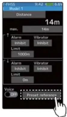
Sensor List
This menu registers the telemetry sensors used with the transmitter. When only one of a certain type of sensor is used, this setting is unnecessary and the sensor can be used by simply connecting it to the S.BUS2 port of the transmitter.
When using 2 or more of the same kind of sensor, they must be registered here.
What is a slot?
Servos are classified by CH, but sensors are classified in units' slots. There are slots from No. 1 to No. 31. Using a sensor which uses two or more slots, the required number of slots is automatically assigned by setting up a start slot. When 2 or more of the same kind of sensor are used, the sensors themselves must allocate unused slots and memorize that slot.
![graph TD A["Home screen"] --> B["Menu screen"] B --> C["Telemetry menu screen"] C --> D["Sensor list"] D --> E["Sensor list 1/4"] E --> F["Sensor list 0/4"] F --> G["Sensor list 2/4"] G --> H["Sensor list 3/4"] H --> I["Sensor list 4/4"] I --> J["Sensor list 5/4"] J --> K["Sensor list 6/4"] K --> L[…](/content/2026/07/1443791/images/f93ee21135a2e503fd40d80d3a986b0557cdf6f2ac20162118e7037e3aa8ea94.jpg)
About the slots that can be used.
As shown in the table below, the current sensor requires three consecutive slots, and the GPS sensor requires 8 consecutive slots. The GPS sensor (SBS - 01 / 02G) has a starting slot of 8.16.24.
| sensor | The required number of slots | The number which can be used as a start slot |
| TEMP (SBS-01T) 1 | slot 1~31 | |
| RPM (SBS01RM) 1 | slot 1~31 | |
| Voltage (SBS-01V) | 2 slot | 1,2,3,4,5,6,8,9,10,11,12,13,14,16,17,18,19,20,21,22,24,25,26,27,28,29,30 |
| Current (SBS-01C) | 2 slot | 1,2,3,4,5,6,8,9,10,11,12,13,16,17,18,19,20,21,24,25,26,27,28,29 |
| GPS (SBS-01/02G) | 8 slot | 8,16,24 |
How to change start slot and set empty slot
1 (Start slot selection)
Tap [Slot], the list of sensors that can be registered in the start slot will be displayed. Sensors that can not be changed are not displayed.
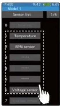
Start slot selection - Tap the slot
2 (Sensor selection)
From the sensor list, tap the sensor you want to register in the start slot. To set as an empty slot, tap [----]. This completes the change.

Sensor selection - Tap the sensor
3 When finished, return to the Sensor list screen by pressing the HOME button.
Sensor
With this menu, you can display the telemetry meter on the home screen.
Also, you can register a telemetry sensor in the transmitter. When using each sensor of the initial setting one by one, setting here is unnecessary. You can use it by connecting the purchased sensor to the S.BUS 2 port of the receiver. If you use multiple sensors of the same type, such as temperature sensor for both battery and motor, you need to register that sensor in the transmitter.
![graph TD A["Home screen"] --> B["Menu screen"] B --> C["Telemetry menu screen"] C --> D["Sensor"] D --> E["FHSS 14:32 7.0V"] E --> F["Sensor list"] F --> G["Reload"] G --> H["Register"] H --> I["Charge slot"] I --> J["Speech interval"] J --> K["Logging interval"] K --> L["Home screen"] L --> M["OFF"…](/content/2026/07/1443791/images/07c5d74b337f7ee74195126de6a412c4f1745eed52828bb5088f06a8949cc492.jpg)

Sensor Reload
When using multiple sensors of the same type the sensors must be registered in the transmitter. Connect all the sensors to be used to the T7PX as shown in the figure below and register them by the following procedure. The ID of each sensor is registered in the transmitter.
To load the sensor, connect all sensors to be used to the T7PX communication port as shown below. Power supply is unnecessary. Also, to clear all sensor registration, execute this [Reload] function without connecting sensor. The registration is cleared and all the slots in the sensor list are unregistered.

How to change start slot and set empty slot
1 (Start slot selection)
Tap the [Reload], The confirmation screen will be displayed. To execute, tap [Yes] to hear an electronic sound and fi nish setting. To cancel, select [No] and tap it. If "Success" appears on the screen, reload is complete.
![graph LR A["Sensor list"] --> B["Reload"] B --> C["Register"] C --> D["Change slot"] D --> E["Speech interval 0"] D --> F["Logging interval 0"] D --> G["Home screen OFF"] B --> H{Are you sure?} H -->|Yes| I["Success"] H -->|No| J["Reloading configuration succeeded"] J --> K["Close"]](/content/2026/07/1443791/images/1fdce3e227ad283aba64df5ec74b4b6f59e5cff14afe568189fc486a12e44cc8.jpg)
2 When fi nished, return to the Telemetry screen by pressing the HOME button.
Sensor Register
This function registers additional sensors. Connect the sensor as shown in the figure and register as follows. The sensor ID is registered in the transmitter.
This function is set when adding one telemetry sensor of the same type.

How to change start slot and set empty slot
1 (Start slot selection)
Tap the [Register], The confirmation screen will be displayed. To execute, tap [Yes] to hear an electronic sound and fi nish setting. To cancel, select [No] and tap it. If "Success" appears on the screen, registration is complete. If registering a sensor that has already been registered is attempted, the message "Failed; The same sensor has been registered" will be displayed. If the message "Failed; The connected sensor is not ready." is displayed, check the sensor connection. If it is securely connected, the sensor or the transmitter may be faulty.

Function
![graph TD A["Sensor"] --> B{Are you sure?} B -->|Yes| C["Reloading configuration succeeded"] B -->|No| D["Success"] E["Register"] --> F{Are you sure?} F -->|Yes| G["Reloading configuration succeeded"] F -->|No| H["Success"] I["Change slot"] --> J{Are you sure?} J -->|Yes| K["Reloading configuration s…](/content/2026/07/1443791/images/6275705eb44c975ac7da2f4e0499fd1bde8fd1f5c38a71f3427dbd548604f037.jpg)
2 When fi nished, return to the Telemetry screen by pressing the HOME button.
Change Slot
This procedure changes the slot number of one registered sensor. Connect the sensor shown in the figure (page 166), and change slot number.
This function is set when using multiple telemetry sensors of the same type.
Sensor slot change
1 (Change)
Tap the [Change slot]. The sensor details screen is displayed. Tap the [Read]. The confirmation screen will be displayed. To execute, tap [Yes] to hear an electronic sound and finish reading. To cancel, select [No] and tap it. If "Reading succeeded" appears and the current sensor information is displayed.
![graph LR A["Sensor"] --> B["Sensor list"] B --> C["Reload"] C --> D["Register"] D --> E["Change slot"] E --> F["Speech interval 0"] E --> G["Logging interval 0"] E --> H["Home screen DFR"] I["Start slot 0"] --> J["Read"] K["Required slots ----"] --> L["Reading succeeded. Close"] M["FHSS 14:32 GMT 7.…](/content/2026/07/1443791/images/421b154cf82ec056aec1c1a0dce7eefa0835cd1ee13d323f7a1253061119a854.jpg)
2 (Number setting)
Tap the value button of the [Start slot #]. Value input buttons appear on the screen. Use the [+] and [-] buttons to set the start slot number.

Setting button
Setting with the [+] and [-] buttons.
3 Tap the [Write]. When "Writing succeeded" message is displayed, the number change is completed.

4 When finished, return to the Sensor screen by pressing the HOME button.
Speech guide interval and log data interval setting
You can set the interval at which to read the voice guide of telemetry information and the interval at which log data is recorded.
Setting interval
1 (Setting of speech interval)
Tap the value button of the [Speech interval]. Value input buttons appear on the screen. Use the [+] and [-] buttons to adjust the speech interval amount.

Adjustment buttons
- Adjust with the [+] and [-] buttons.
- Return to the initial value by tapping the [reset] buttons.
Speech interval
0\~30 sec Initial value: 0
2 (Setting of logging interval)
Tap the value button of the [Logging interval]. Value input buttons appear on the screen. Use the [+] and [-] buttons to adjust the logging interval amount.
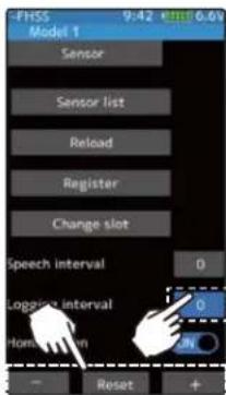
Adjustment buttons
- Adjust with the [+] and [-] buttons.
- Return to the initial value by tapping the [reset] buttons.
Logging interval
0\~30 sec Initial value: 0
3 When finished, return to the Telemetry screen by pressing the HOME button.
Telemetry meter display on home screen
Telemetry information on the home screen, graphic meter can be displayed.
Display of telemetry meter
1 (Function ON/OFF)
Tap "Home screen" (ON) or (OFF) to select ON / OFF.
"OFF": Telemetry meter not displayed
"ON": Telemetry meter display
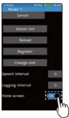

3 When finished, return to the Telemetry screen by pressing the HOME button.
Telemetry meter display settings
Five telemetry meters displayed on the home screen are displayed. You can select the sensor to display and set the range of display data. It can be set for each meter.
![graph TD A["Home screen"] --> B["Tap meter to set display range etc."] B --> C["Display the screen to select the sensor to be displayed."] C --> D["When the sensor to be displayed can measure multiple data, select which data to display."] D --> E["Set the upper limit / lower limit displayed on the m…](/content/2026/07/1443791/images/a5991b3de773e9be412947a8bd9ca2e7b8619e07fcff8e624f812d4c32ff02c8.jpg)

Function
Model Select
Forty model data (model data for 40 R/C cars) can be saved in the T7PX transmitter and used when the relevant model data is called. However, models copied in the microSD card can not be used by directly calling from the card. Please copy it to the T7PX main user when using it.
![graph TD A["Home screen"] --> B["Menu screen"] B --> C["Model menu screen"] C --> D["Model select"] D --> E["Model 1"] D --> F["Model 2"] D --> G["Model 3"] D --> H["Model 4"] D --> I["Model 5"] D --> J["Model 6"] D --> K["Model 7"] D --> L["Model 8"] E --> M["Model where green cursor is currently i…](/content/2026/07/1443791/images/2df6189e68f16cacfc240e5d3b6d71ad467448fa6f876c1bb01b49cda2a7811b.jpg)
Using the model selection function
1 (Model memory selection)
You can choose from 8 models on 1 page and 40 models on 5 pages. Tap the ◀▶ mark at the bottom of screen to move the page.
Model #.
M1\~M40
Model selection
- Tap the [Model name]
2 (Model selection execution
Tap the [Model name] to use, a confirmation screen will be displayed saying "Are you sure?" To execute, tap [Yes], a beep sounds and the change is completed and the home screen is displayed. To cancel, tap [No] and tap.
- If the model name of the home screen is changed, model selection is completed.
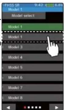

3 When fi nished, return to the Model menu screen by pressing the HOME button.
Model Copy
The contents of the model memory can be copied to another model memory. The contents can also be saved or stored on a microSD card for copying to another T7PX.
![graph TD A["Home screen"] --> B["Menu screen"] B --> C["Model menu screen"] C --> D["Model copy"] D --> E["Model copy from Internal memory"] E --> F["Copy to Internal memory"] F --> G["Copy"] G --> H["User mouse icon"] H --> A](/content/2026/07/1443791/images/a65fde3f3142126f060f17dba4ae4410cf18694bac3b22c668e6fe3ced8caa8c.jpg)
Model copying
1 (Copy source model selection)
You can choose from 8 models on 1 page and 40 models on 5 pages. Tap the ◀▶ mark at the bottom of screen to move the page.
Copy source
Tap to select from the list
2 (Model selection execution
Tap the "Copy from" [model name], select the model list so it will tap. The source model is selected and the model list is closed. The list is the same design as the model select and the way of moving the page is the same. If a microSD card is installed in the T7PX main unit, a button for selecting either the model inside the T7PX main unit or the model inside the microSD card will be displayed, so tap to select it. To cancel, press the HOME button to return to the model copy screen.

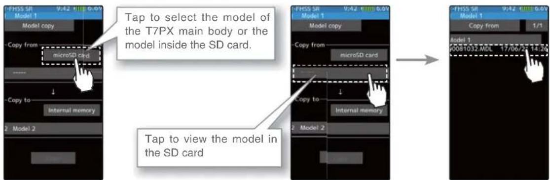
3 (Copy destination model selection)
Tap the "Copy to" [model name], select the model list so it will tap. The source model is selected and the model list is closed.
-The model currently in use cannot be selected.
- Since the copy destination cannot be overwritten when it is in a microSD card, a models list is not displayed and the model is saved directly to the microSD card.

Copy destination
Tap to select from the list

4 (Copy execution)
Tap the [Copy], The confirmation message "Are you sure" appears. To execute copy, tap [Yes] and to cancel copy, select [No]. When the copy destination model name becomes the same name as the copy source, copying is complete.

Copy execution
Tap the [Copy]

5 When finished, return to the Model menu screen by pressing the HOME button.

microSD card storage destination
When a microSD card is installed in the T7PX, a folder called "Futaba" is created, and folders called "LOG" and "MODEL" are created in it. The "MODEL" folder contains the model data.

![graph LR A["FUTABA"] --> B["LOG MODEL"] B --> C["Model data\n00010701.MD\n00022499.MD\n00039367.MD"]](/content/2026/07/1443791/images/8f1a2ea07872ffb2e9444736af353035c4eeeb7c47e8a5ddd55356547eee7950.jpg)
When the T7PX model data is copied, and the copy source data is selected from the model data stored in the microSD, a model list like that shown at the left is displayed.
Model Name
This function allows you to assign a ten character name to each model memory.
![graph TD A["Home screen"] --> B["Menu screen"] B --> C["Model menu screen"] C --> D["Model name"] D --> E["Move cursor"] E --> F["Deletion and cancellation of characters (Undo)"] E --> G["Tap to select characters"] E --> H["Selection of alphabet / number / "kana""]](/content/2026/07/1443791/images/5c7365dac42587d29652ce222c6631da5336bfc9be78dc4946f4b4cc2945947f.jpg)
Setting the model name and user name
1 (Moving the cursor to the character you want to change.) In the model name, tap [←], [→] to move the cursor and select the character of the model name you want to set or change. A vertical line cursor is displayed before the selected character.
2 (Selection of characters to use)
Select the character to use from the character list. When you decide the character to use, tap it. The character is determined and the character string of the model name moves to the right. If you tap [BS], the left character of the vertical line cursor will be deleted. To redo, tap [Undo].
3 When fi nished, return to the Model menu screen by pressing the HOME button.
Name cursor movement
Use the [←] / [→] tap to move the cursor. Also, when you decide a character, when the cursor position of the model name moves to the right, the cursor position of the model name moves to the right.
Select / determine character
Select a character, tap it to determine the character
Model Delete (Model saved on microSD card)
This function deletes model data saved on the microSD card.
Model deletion is displayed on the menu only when microSD card is set in the T7PX card slot.
![graph TD A["Home screen"] --> B["Menu screen"] B --> C["Model menu screen"] C --> D["Model delete"] D --> E["User interface"] E --> F["User mouse icon"] F --> B B --> G["User mouse icon"] G --> C C --> H["User mouse icon"] H --> I["User mouse icon"] I --> D D --> J["User mouse icon"] J --> K["User m…](/content/2026/07/1443791/images/98e11d9f5c06b41a934d466d68dd7074988c5e1de4379e0cb689a07b54a18805.jpg)
How to delete model data in microSD card
1 (selection of model data)
If the number of models that does not fit on one page is memorized, tap [1/2] in the upper right corner to move the page.
If there are 2 pages, it will be displayed as [1/2] / [2/2], if there are 5 pages, it will be displayed as [1/5] to [5/5].
2 (execution of model deletion)
Tap the model you want to delete. A confirmation message "Are you sure?" appears. Tap [Yes] to execute the deletion, or [No] to cancel.
"Deleting succeeded" is displayed and deletion is completed.

Delete execution Tap the [model data]

3 When finished, return to the Model menu screen by pressing the HOME button.

Data Reset
This function resets the contents of the currently called model memory.
The reset method can be selected from among the 4 types described below. These resets do not initialize the adjuster function and system function.
-Model data
Initializes only the function setting data. The direct menu function is not initialized.
-User menu
Initializes the user menu function. Other settings are not initialized.
-Telemetry
Telemetry related setup data is initialized.
-All data
Initializes the direct selection function, receiver setting function and the setting data of each function.
![graph TD A["Home screen"] --> B["Menu screen"] B --> C["Model menu screen"] C --> D["Data reset"] subgraph Home screen E["User name"] --> F["User icon"] F --> G["User icon"] G --> H["User icon"] H --> I["User icon"] I --> J["User icon"] J --> K["User icon"] K --> L["User icon"] L --> M["User icon"]…](/content/2026/07/1443791/images/729ddc9dd33f95fb5d7c65534148d506132aa5338bd137c1af3d58d4437778af.jpg)
Data Reset
1 1 (Execution of reset)
Select the type you want to reset and tap. A confirmation message will be displayed as "Are you sure?" If you want to execute, tap [No] to cancel with [Yes]. Reset is now complete.

Reset execution
Tap the [reset type]
Reset type
-Model data
-User menu
-Telemetry
-All data

2 When finished, return to the Model menu screen by pressing the HOME button.
Display
Backlight brightness, dimming time etc. setting and touch panel correction menu.
There is also a touch panel sensitivity adjustment.
![graph TD A["Home screen"] --> B["Menu screen System menu screen"] B --> C["Display"] C --> D["Touch panel"] D --> E["Display"] E --> F["Display"] F --> G["Display"] G --> H["Display"] H --> I["Display"] I --> J["Display"] J --> K["Display"] K --> L["Display"] L --> M["Display"] M --> N["Display"] N…](/content/2026/07/1443791/images/cc45f524fad2c8f851af5e8140726c95c34f7c880b9f674b811b8532bf18980d.jpg)
Display setup
1 (Backlight decrease brightness adjustment)
Tap the value button of the [Backlight max, brightness] or [Backlight min, brightness]. Value input buttons appear on the screen and use the [+] and [-] buttons to adjust the backlight decrease brightness amount.
2 (Backlight decrease time)
You can set a time period to decrease the LCD backlight. This function counts the period that the touch panel has been not operated. This time can be set by one second steps. You can also turn off the backlight decrease if you like.
Tap the value button of the [Backlight decrease time]. Value input buttons appear on the screen and use the [+] and [-] buttons to adjust the backlight decrease time amount.
3 (Touch panel correction)
Tap [Calibration]. It will be a black screen with a white + mark at the center of the screen. Tap on the intersection of that + mark in order, using a stylus pen is the best recommendation. To cancel, press the HOME button to return to the display setting screen.
Adjust button
Adjust with the [+] and [-] buttons.
- Return to the initial value by tapping the [reset] buttons.
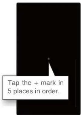
4 (Touch panel sensitivity adjustment)
You can adjust the sensitivity of the touch panel.
Tap the value button of the [Sensitivity]. Value input buttons appear on the screen and use the [+] and [-] buttons to adjust the sensitivity of the touch panel. The higher the number the more sensitive the screen is.
5 (Touch Panel Vibrate ON / OFF)
The vibrate can be operated by the operation of the touch panel. Tap on the "Vibrator" (ON) or (OFF) and select ON / OFF.
"OFF": Function OFF
"ON": Function ON
6 (Setting of start / end screen)
This is for the "Opening Demo" On/Off switch or icon. This turns the "Futaba T7PX" on or off when powering the transmitter on or off.
Tap on the "Opening demo" (ON) or (OFF) and select ON / OFF.
"OFF": Function OFF
"ON": Function ON
7 When finished, return to the System menu screen by pressing the HOME button.
Adjust button
Adjust with the [+] and [-] buttons.
- Return to the initial value by tapping the [reset] buttons.
Sensitivity
10\~100
Initial value: 30
Setting
- Tap (ON) / (OFF).
Setting
- Tap (ON) / (OFF).
Information
With this system information, you can select user name setting, display language, use unit of telemetry information. Also displays the software version.
![graph TD A["Home screen"] --> B["Menu screen System menu screen"] B --> C["Information"] C --> D["Move cursor"] D --> E["Deletion and cancellation of characters (Undo)"] D --> F["Tap to select characters"] D --> G["Selection of alphabet / number / "kana""]](/content/2026/07/1443791/images/0c72d25db6bf30405958de8635bbf9268dea47b472e5c4e93f08359aa6ccd363.jpg)
Setting the user name
1 (Moving the cursor to the character you want to change.) In the model name, tap [←], [→] to move the cursor and select the character of the model name you want to set or change. A vertical line cursor is displayed before the selected character.
2 (Selection of characters to use)
Select the character to use from the character list. When you decide the character to use, tap it. The character is determined and the character string of the model name moves to the right. If you tap [BS], the left character of the vertical line cursor will be deleted. To redo, tap [Undo].
Name cursor movement
Use the ( [-] / ( [\rightarrow] ) tap to move the cursor. Also, when you decide a character, when the cursor position of the model name moves to the right, the cursor position of the model name moves to the right.
Select / determine character
Select a character, tap it to determine the character
3 When fi nished, return to the System menu screen by pressing the HOME button.
Language setting
1 (Language select)
Tap [Language], a list of languages will be displayed on the screen. If you tap the language you want to use from the list, the language display will be changed and you will be taken to the home screen.
-The available languages will be added in the future.

Language select
Tap to select from the list
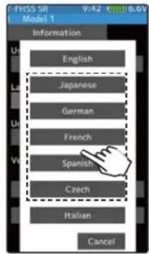
Units system setting
1 (Units system setting)
Tap [Unit System] and set it to either the metric method or the yard / pound method.

Setting
- Tap Units system Meric system Yard-pound system
Display of manufacturer information and open source license
1 (Show the manufacturer information and open source license)
Tap [Open source license], displays the manufacturer information and the license information of the font used in the system.

3 When finished, return to the System menu screen by pressing the HOME button.
Sound
This function can set the volume of "Operation", "Warning" and "Telemetry speech info".
-The volume of when switch, dial, home button, and trim are operated can be adjusted.
-The volume of the audible alarm sound can be adjusted.
-When the telemetry function is used, the volume of the voice that announces the temperature, speed, voltage, and other information at a fixed interval can be adjusted.
![graph TD A["Home screen"] --> B["Menu screen"] B --> C["System menu screen"] C --> D["Sound"] D --> E["User interface"] E --> A style A fill:#f9f,stroke:#333 style B fill:#ccf,stroke:#333 style C fill:#cfc,stroke:#333 style D fill:#fcc,stroke:#333 style E fill:#cff,stroke:#333](/content/2026/07/1443791/images/f45bbd212e245456d84a1bf05321fba8688687077e9e9384b944c9a0941bd2dd.jpg)
Volume adjustment
1 (Adjusting the key operation volume)
Tap the value button of the [Normal volume]. Value input buttons appear on the screen and use the [+] and [-] buttons to adjust the volume.
2 (Adjusting the warning volume)
Tap the value button of the [Warning volume]. Value input buttons appear on the screen and use the [+] and [-] buttons to adjust the volume.
3 (Adjusting the voice volume)
Tap the value button of the [Voice volume]. Value input buttons appear on the screen and use the [+] and [-] buttons to adjust the volume.
Adjust button
Adjust with the [+] and [-] buttons.
- Return to the initial value by tapping the [reset] buttons.
Normal volume
0\~32
Initial value : 16
Warning volume 1\~32
Initial value : 16
Voice volume
0\~32
Initial value : 16
4 When finished, return to the System menu screen by pressing the HOME button.
Battery
With the T7PX, the low battery alarm setting is different, depending on the type of battery. Therefore, always set the battery type matched to the power supply to be used.
When using a Futaba rechargeable type battery, always select 2 cells or "NiMH 5 cells". Incorrect setting will substantially shorten the time from low battery alarm to system stopping and is very dangerous.
Exceptionally, when using a battery other than this, select "Other" and set the low battery alarm voltage on your own responsibility. Futaba is not responsible for trouble caused by use of an unspecified battery.
![graph TD A["Home screen"] --> B["Menu screen"] B --> C["System menu screen"] C --> D["Battery"] D --> E["Battery type: Life 2cells"] D --> F["Vibrator: Inhibit"] D --> G["Auto power off: OFF"] B --> H["Display"] B --> I["Information"] B --> J["Switch"] B --> K["Battery: Data and Time"] C --> L["Disp…](/content/2026/07/1443791/images/9c8d573cfeab20c8d5e49440b60fd349b5de785ddb1afa82168ce47c11ebe643.jpg)
Battery setting
1 (Select battery type)
Tap [Battery type], a list of battery type will be displayed on the screen. tap the battery type you want to use from the list.
-When set to [Other], please set the alarm voltage by yourself.
2 (Select vibrator type)
Tap the [Vibrator] type and select [Inhibit], [Type 1], [Type 2], or [Type 3].
3 (Auto power off setting)
Tap on the "Auto power off" (ON) or (OFF) and select ON / OFF.
"OFF": Function OFF
"ON": Function ON
4 When finished, return to the System menu screen by pressing the HOME button.
Setting
- Tap list
LiFe 2 sell
NiMH 5 cell
Other
Setting
- Tap Vibrator type.
Inhibit/ Type 1/ Type 2/ Type 3
Setting
- Tap (ON) / (OFF).
Data And Time
This function adjusts the system clock of the T7PX transmitter. Perform this: when you purchase the set and when adjustment is necessary.
Whether the time or the total time (accumulation timer) is displayed on the in screen can be set. The total timer can be reset at this menu.
![graph TD A["Home screen"] --> B["Menu screen"] B --> C["System screen"] C --> D["System menu screen"] D --> E["Data and time"] E --> F["Clock 2000 / 01 / 01"] F --> G["Total timer 27:14:40 Reset"] G --> H["Display mode Clock"] H --> I["User interface"] I --> J["User interface"] J --> K["User interfa…](/content/2026/07/1443791/images/663c325771635fa2e6f57421d82defadb96e2d92454e5056e13cd70496465fe8.jpg)
Date and time setting
1 (Date and time setting)
Tap the value button of the [Year], [Month], [Day], [Hour], [Minute] or [Second]. Value input buttons appear on the screen. use the [+] and [-] buttons to set the date and time amount. When the setting is changed, the [Time adjust] button will be displayed, so tap this to update the system clock.
- The date and time will be reset after a long period of time with the battery removed from the transmitter.

Adjust button
Adjust with the [+] and [-] buttons.
- Return to the initial value by tapping the [reset] buttons.
Timer reset
tap the [reset]
2 (Total time reset)
Tap the [Reset]. The total time is reset.
Setting
- Tap display mode.
Clock
Total time
3 (Select home screen display mode)
Tap on the "Display mode" [Clock] or [Total time] and select Clock / Total timer.
4 When finished, return to the System menu screen by pressing the HOME button.
LED Setting
You can adjust the brightness and lighting method of the pilot LED light.
The pilot LED lighting method can be selected from "always on", "off" or "interlock with backlight".
![graph TD A["Home screen"] --> B["Menu screen System menu screen"] B --> C["LED Setting"] C --> D["LED setting"] D --> E["User interface"] E --> A B --> F["Display"] B --> G["Information"] B --> H["Sound"] B --> I["Battery"] B --> J["Data and Time"] B --> K["LED setting"] B --> L["Color space"] B -->…](/content/2026/07/1443791/images/73e9dadafd000ad34b0fe73b9092f4507ab646c3d84392863cec9ad413343e0d.jpg)
LED setting
1 (Setting pilot LED)
Tap the [Pilot LED], a list of lighting mode will be displayed on the screen. tap the lighting mode you want to use from the list.

Pilot LED mode
Backlight, Always On, OFF

Function
2 (Setting Pilot LED brightness)
Tap the value button of the [Brightness]. Value input buttons appear on the screen and use the [+] and [-] buttons to adjust the pilot LED brightness amount.
Adjust button
Adjust with the [+] and [-] buttons.
- Return to the initial value by tapping the [reset] buttons.
Brightness
0\~20
Initial value : 20
3 When finished, return to the System menu screen by pressing the HOME button.
Calibration
Steering and throttle correction can be applied. Use this function when a mechanical offset has occurred for some reason.
However, if correction was applied, it may be necessary to recheck the set values of all the setup functions.
![graph TD A["Home screen"] --> B["Menu screen System menu screen"] B --> C["Calibration"] D["User interface"] --> A E["User interface"] --> B F["User interface"] --> C G["User interface"] --> D H["User interface"] --> I["User interface"] J["User interface"] --> K["User interface"] L["User interface"]…](/content/2026/07/1443791/images/17537cf058da75f72f6ff99e462ec3116d544675da1d0cde787bb09d11a24157.jpg)
Steering adjustment
(Preparation)
Tap the [Wheel]. The neutral correction screen appears.
1 (Steering neutral adjustment)
At neutral, turn the steering wheel left and right. Press the [Neutral] button while the steering wheel is in its neutral position. If the [Neutral] position is OK, the [End Point] button will appear after pressing the [Neutral] button. If not within the correction range, the [End Point] button will not appear.
2 (Steering wheel travel adjustment)
With [End Point], slowly rotate the steering wheel left and right, tap the [End Point] button. If the [End Point] correction is OK, the display will return to the calibration screen. If the end point is not within the correction range, the display does not return to the adjuster screen. In this case, return to the system menu screen by pressing the HOME button. If operation cannot be ended normally even when correction is repeated, please contact the Futaba Service Center.
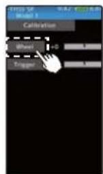
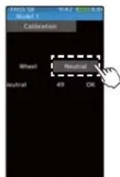

3 When finished, return to the System menu screen by pressing the HOME button.
Throttle adjustment
(Preparation)
Tap the [Trigger]. The neutral correction screen appears.
1 (Throttle neutral adjustment)
At neutral, pull the throttle trigger to full throttle and to the brake position. Press the [Neutral] button while the trigger is in its neutral position. If the neutral position is OK, the [End Point] button will appear after pressing the [Neutral] button. If not within the correction range, the [End Point] button will not appear. If not within the correction range, the end point correction screen will not appear.
2 (Throttle trigger travel adjustment)
With [End Point], pull the throttle trigger to full throttle and back for braking, tap the [End Point] button. If the [End Point] correction is OK, the display will return to the calibration screen. If not within the correction range, the display will not return to the adjuster screen. In this case, return to the system menu by pressing the HOME button. When operation cannot be ended normally even when correction is repeated, and cannot be ended normally, contact the Futaba Service Center.

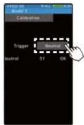

3 When finished, return to the System menu screen by pressing the HOME button.
Software Update
If software updates are required in the future, there are two ways of doing so. One is the use of a MicroSD memory card, the other is the use of NFC communication. The use of Android devices such as cell phones, tablets is possible. Download the Futaba app from Google Play. The software update screen is displayed on display mode.
![graph TD A["Home screen"] --> B["Menu screen System menu screen"] B --> C["Software update"] C --> D["Software update"] D --> E["Display Model 1 13:52 6.7k Software update"] B --> F["Display Model 1 14:28 6.7k System menu"] B --> G["Sound"] B --> H["Battery"] B --> I["Date and Time"] B --> J["LED se…](/content/2026/07/1443791/images/3d80caffb900f2982f9536b65a9e805122bf773fc65ada7a35f2413cf92dabc7.jpg)

We can not guarantee that all devices can update. Depending on the model of the device, the update may not start. In that case please update with SD card.

The N-Mark is a trademark or registered trademark of NFC Forum, Inc. in the United States and in other countries.
Date and time setting
1 Launch the T7PX application on an Android device compatible with NFC, and place the NFC mark of the device on the NFC mark of T7PX referring to the figure above. Download of update data will start.
* If the message "The downloaded file is broken. Please try again." Is displayed, communication has not been performed normally. Please redis-play T7PX and terminal screen and try again.

2 When the update is successfully completed, the T7PX will restart.
Specifications
*Specifications and ratings are subject to change without prior notice.
Transmitter T7PX
Wheel system, 7 channels (SFHSS System), 4 channels with TFHSS-SR, T-FHSS, FASST systems.
- Transmitting frequencies 2.4GHz band /- Transmitting RF power output: 100mW EIRP
- Futaba T-FHSS SR/T-FHSS/S-FHSS/FASST-C2
- Power requirement
(Ni-MH battery) NT5F1800B (6V)
(LiFe battery) FT2F1700BV2 (6.6V)
- Current drain 350mA or less (When the T-FHSS, Vibration off, back lighting on)
- Transmitting antenna 1/2λdipole
- 4.3 inch backlighted color TFT liquid crystal touch panel.
*When you turn on your 7PX, bright dots may appear on your screen display. Your display contains an extremely large number of TFT and is manufactured using high-precision technology. Any bright dots that may appear on your display are intrinsic of the TFT manufacturing technology.
Receiver R334SBS / : (T-FHSS SR /T-FHSS system, 4 channels)
- Receiving frequency: 2.4GHz band /- Telemetry Receiver RF power output: 10mW EIRP
- Power requirement: 3.7V\~7.4V battery (Dry cell battery cannot be used.)
- System: S-FHSS SR/T-FHSS system (auto detection) /S.BUS2 system
- Size: 1.34x0.88x0.45" (33.9x22.3x11.3mm) (excluding a projection part) /- Weight :0.23oz. (7.5g)
Caution
- Be sure to use the T7PX receiver setting and the servo to be used under predetermined conditions.
Under other conditions, the set will not operate, or the specified performance will not be displayed even if it operates. In addition, it may cause servo trouble. Futaba will not be responsible for problems caused by the use of other than genuine Futaba parts. Use the parts specified in the instruction manual and catalog.
| System | Response / SR node Usable | servos |
| T-FHSS SR | SR mode channel: ON | - SR mode of Futaba SR compatible servo. |
| SR mode channel: OFF | - Normal mode of Futaba SR compatible servo.- Futaba digital servo. | |
| T-FHSS | Digital servo | - Normal mode of Futaba SR compatible servo.- Futaba digital servo. |
| Analog servo | - Futaba all servo.(Normal mode of Futaba SR compatible servo.) | |
| S-FHSS | Digital servo | - Normal mode of Futaba SR compatible servo.- Futaba digital servo. |
| Analog servo | - Futaba all servo.(Normal mode of Futaba SR compatible servo.) | |
| FASST | Digital servo | - Normal mode of Futaba SR compatible servo.- Futaba digital servo. |
| Analog servo | - Futaba all servo.(Normal mode of Futaba SR compatible servo.) |
Receiver's battery: Matched to the ratings of the receiver and connected servo (dry cell battery cannot be used).
In addition, the FSU Fail Safe Unit cannot be used because the system is different. Use the fail safe function of the transmitter.
Parameter by type of servo for SR mode
When setting SR mode compatible servo to SR mode with S. BUS servo menu, choose from 3 types. The table below shows the initial setting parameter table by type.
| SR mode compatible servos | SR type Frequency | Frequency | Dead band | Damper Smoother | Strecher | Strecher Boost | Boost | |
| BLS371SV | Type1 | 2 0.11 | 68 INH | 4.000 | ACT | 12 | ||
| Type2 | 3 0.11 | 68 INH | 4.000 | ACT | 14 | |||
| Type3 | 4 0.11 | 64 INH | 2.500 | ACT | 18 | |||
| BLS471SV | Type1 | 2 0.11 | 66 INH | 1.250 | ACT | 20 | ||
| Type2 | 3 0.11 | 58 INH | 0.875 | ACT | 20 | |||
| Type3 | 4 0.11 | 60 INH | 1.000 | ACT | 20 | |||
| BLS571SV | Type1 | 2 0.11 | 48 INH | 2.500 | ACT | 10 | ||
| Type2 | 3 0.11 | 40 INH | 2.500 | ACT | 10 | |||
| Type3 | 4 0.11 | 40 INH | 2.500 | ACT | 20 | |||
| BLS671SV | Type1 | 2 0.11 | 44 INH | 4.000 | ACT | 14 | ||
| Type2 | 3 0.11 | 48 INH | 4.000 | ACT | 20 | |||
| Type3 | 4 0.11 | 40 INH | 4.000 | ACT | 20 | |||
| S9372SV S9373SV | Type1 | 2 | 0.11 | 50 | ACT | 1.500 | ACT | 10 |
| Type2 | 3 | 0.11 | 82 | ACT | 1.250 | ACT | 14 | |
| Type3 | 4 | 0.11 | 86 | ACT | 2.000 | ACT | 20 | |
| O.S.SPEED T-1 | Type1 | 2 0.11 | 56 INH | 2.500 | ACT | 10 | ||
| Type2 | 3 0.11 | 48 INH | 2.000 | ACT | 10 | |||
| Type3 | 4 0.11 | 48 INH | 2.000 | ACT | 20 | |||
| O.S.SPEED R-1 | Type1 | 2 0.11 | 72 INH | 3.000 | ACT | 12 | ||
| Type2 | 3 0.11 | 72 INH | 2.500 | ACT | 12 | |||
| Type3 | 4 0.11 | 80 INH | 2.500 | ACT | 16 | |||
| O.S.SPEED B-1 | Type1 | 2 0.11 | 88 INH | 2.000 | ACT | 10 | ||
| Type2 | 3 0.11 | 96 INH | 2.000 | ACT | 10 | |||
| Type3 | 4 0.11 | 96 INH | 2.000 | ACT | 20 |
System Compatibility
The 7PX is a 2.4GHz T-FHSS SR and T-FHSS surface system. The transmitter can also be switched to S-FHSS and FASST. (However, the telemetry system can be used T-FHSS only.) The usable receivers are shown below.
| Communications System | Usable Receivers |
| T-FHSS SR/T-FHSS (Default) | R334SBS |
| T-FHSS | R304SB/ R304SBE |
| S-FHSS (Change is possible) | R2104GF/ R204GF-E/ R2008SB/ R2006GS*The analog servo mode of the S-FHSS system can use up to 7 channels. When using 5 or more channels, R2008SB and R2006GS can be used. |
| FASST (Change is possible) | R614FS/ R614FF-E/ R604FS/ R604FS-E |
*R3008SB, T-FISS Air system receivers do not operate.
Warning Displays
Low Battery Alarm

If the transmitter battery voltage drops below the usable range, an audible alarm will sound and "Low battery" will be displayed. Since the usable range of LiFe and NiMH batteries are different, the power supply used must be set by system setting. (page 181)
Audible alarm: Continuous tone.
The vibrator: Active (initial setting) page 181
⚠ Warning
When a low battery alarm is generated, cease operation immediately and retrieve the model.
If the battery goes dead while in operation, you will lose control.
Power off forgotten alarm

At T7PX initialization, if steering wheel, throttle trigger, push switch, HOME button, or other operation is not performed within 10 minutes, an audible alarm will sound and the message "Warning: Auto power off" will appear. If steering wheel, throttle trigger, push switch, HOME button or other operation is performed, the alarm is reset. Also turn off the power when the transmitter is not in use. If you do not want to use this alarm and the auto power off function, they can be disabled by system setting. (page 181)
Audible alarm: Continuous tone.
- If the alarm is not reset, the auto power off function will automatically turn off the power after 5 minutes.
MIX Warning
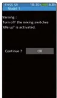
When the power switch is turned on while the idle-up, engine cut or neutral brake function switch is on, an audible alarm will sound and "Warning" will be displayed on the LCD. When that function switch is turned off, the alarm will stop.
Audible alarm: Continuous tone.
- The alarm stops even if the [OK] is tapped. However, check the function switch.
RF Error

When the RF module does not operate "RF Error" is displayed on the LCD and an audible alarm will sound. Immediately turn off the power.
Audible alarm: Continuous tone.
- To stop the alarm, turn off the power.
- Turn the power back on. If the alarm is generated again, request repair from the Futaba Service Center.
Backup Error
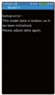
If the data in the transmitter is not transferred normally when the power is turned on, an audible alarm will sound and "Backup error" will be displayed on the LCD.
Audible alarm: Continuous tone.
- To stop the alarm, turn off the power.
- Turn the power back on. If the alarm is not generated again, there is no problem.
System Error

If the data is lost for an unknown reason, an audible alarm will sound and "System error" will be displayed on the LCD screen.
Audible alarm: Continuous tone.
⚠ Warning
When a system error is generated, immediately stop using the system and request repair from the Futaba Service Center. If you continue to use the system, the transmitter may malfunction and cause loss of control.
T7PX Screen Protector
*Protect the screen from scratches and dirt.
* Slightly smaller than the T7PX screen size, so it attaches sticks tight.
*The protector has a front and back backing.
How to attach the protector
1 Clean your screen using a glass cleaner with a lint-free microfiber cloth. Wipe off the dust from the screen thoroughly before applying the screen protector. (Dust and dirt are the reasons for air bubbles underneath the protector.)
2 Remove one side of the plastic backing. Along one edge about one inch and fold down the backing to expose the protector. Be careful not to touch the screen protector. Align the screen protector along the edge of the screen. Be sure to attach the exposed one inch of the protector film straight to the screen. Press the clean screen protector gently and steadily, press on the screen surface as you peel the backing away. Or gently slide a credit card over the surface, use as a squeegee to get as many of the air bubbles out for you. Slowly press out any air bubbles.
3 After attaching the protector is done, remove the front backing.
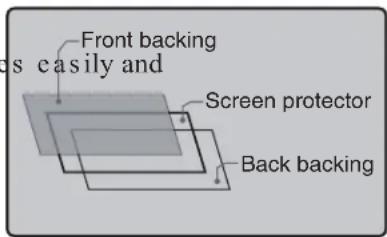
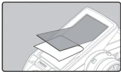
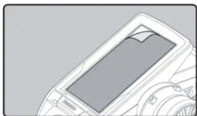
Optional Parts
The following parts are available as T7PX options. Purchase them to match your application. For other optional parts, refer to our catalog or web site. www.futabarc.com.
Transmitter Battery
When purchasing a transmitter battery use the following:
Part name
HT5F1800B (6V/1800mAh) Ni-MH battery
FT2F1700B(6.6V/1700mAh)/2100BV2 (6.6V/2100mAh) Li-Fe battery
Please do not use the transmitter batteries HT5F1800B and FT2F1700/2100BV2 as a receiver battery.
Telemetry sensors
Usable sensor options (As of July 2017)
-Voltage Sensor (SBS-01V) Measures external power supply voltages up to 100V.
-Temperature sensor (SBS-01T) Perfect for engine head, etc.
-Temperature sensor (SBS-01TE) Used by attaching to a motor, etc.
-RPM Sensor (SBS-01RM) Measure the rotation speed over the 0 to 999,900rpm range.
-RPM Sensor (SBS-01RB) Measure the rotation speed over the 360 to 300,000rpm range. (Brushless type)
-Current sensor (SBS-01C) Measures external power supply voltages up to 70V, capacity and consumption capacity.
-GPS sensor (SBS-01G) Speed and Distance
T7PX / T4PX Angle spacer
This Angle spacer is option part for T7PX. Angle of a steering wheel can be changed.
Refer to the page 28 of this manual for means of attachment.
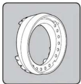

Example of installing angle spacerAngle spacer
T7PX / T4PX Large grip (for transmitter)
This handle grip is larger than the standard handle grip.
It is perfect for those with large hands.
Remove and replace the standard handle grip.
Large grip is standard for the US, and normal (smaller) type is an optional part.

Carbon handle (for transmitter)
An optional carbon handle can be installed to the T7PX. Use the 2.5 hex wrench supplied with the 7PX set to install it. The screws (3x10mm) are supplied with the optional carbon handle.


These aluminum brake levers provide different finger gap from the original.

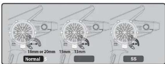
When requesting repair
Before requesting repairs, please recheck your system to see if the problem persists. If so, read the following for service.
(Information needed for repair)
Describe the problem in as much detail as possible and send the letter along with the system in question.
- Symptom (Including the conditions and when the problem occurred)
- R/C System (Send transmitter, receiver and servos)
- Model (Type of model, brand name and model number or kit name)
- Detailed packing list (Make a list of all items sent in for repair)
- Your name, address and telephone number.
(Warranty)
Read the Warranty card.
- When requesting warranty service, send the card or some type of dated proof purchase.
- No part of this manual may be reproduced in any form without prior permission.
- The contents of this manual are subject to change without prior notice.
- This manual has been carefully written. Please write to Futaba if you feel that any corrections or clarifications should be made.
- Futaba is not responsible for the use of this product.
©Copyright 2018. No part of this manual may be reproduced in any form without prior permission. The contents of this manual are subject to change without prior notice. While this manual has been carefully written, there may be inadvertent errors or omissions. Please contact our service center if you feel that any corrections or clarifications should be made.
FUTABA CORPORATION
oak kandakajicho 8F 3-4 Kandakajicho, Chiyoda-ku, Tokyo 101-0045, Japan
TEL: +81-3-4316-4820, FAX: +81-3-4316-4823
7PX
7PX Telemetry System
T7PX Software Update Method
Whenever improvements and new functions are available, the software of your T7PX radio transmitter can be updated easily online free of charge. The updated software file will be shown on our website. You can download it and make a copy on your microSD card. Below is the procedure for the software update.
Procedure for the software update
Caution: Before you update the software, the battery that is connected to the T7PX should be fully charged.
Note: During the software update, the model data that is stored in the T7PX should be kept without any change. (NOT erased and NOT changed.) However, for your safety, making a backup of your model data before the software update is highly recommended.
I. Download the zip file of the update data from our website.
2. Extract the zip file on your computer.
3. The "FUTABA" folder will be created on your computer.
4. Copy the "FUTABA" folder onto your microSD card.
Note: If the microSD card has already had "another FUTABA" folder before you make a copy, the "FUTABA" folder is OVERWRITTEN.
- Insert the microSD card with "FUTABA" folder that contained the update software into the SD card slot on your T7PX radio transmitter.

- Turn on the transmitter power while pressing down the "HOME" button. The update
screen appears on the LCD display of your T7PX and the software update is started.


- When the software update is completed, "Completed" message is shown on the LCD display of your T7PX. (See attached picture.)

- Turn off the power switch of your T7PX and remove the microSD card from the card slot.
Possible Problems
When one of the error messages shown below appears on the LCD screen of your T7PX, the software update will not be completed.
"Low battery."
Software update is postponed because of low battery. Retry the software update after the battery is recharged.
"Update file not found."
The T7PX cannot find the update file on the microSD card. Check to be sure all the update files have been copied onto the microSD card.
"Broken file."
The T7PX detects the update file error. The update file may be broken or for another transmitter.
"Write error."
The software update procedure is stopped for an unknown reason. Contact your local service center when this error message appears on the LCD screen of your T7PX.
Futaba S.BUS / S.BUS 2 The "S. BUS servo" function (Instruction manual page 135) that allows you to change the servo parameters can now be set up wirelessly by connecting to the receiver.
* A receiver compatible with the wireless setting function is required. (As of April 2018, R334SBS / R334SBS-E is compatible with wireless setting. Please update the previous receiver to version 2.0 or later.)
WARNING
●In the wireless setting, there is a danger that a car (boat) can become unexpectedly uncontrollable, because the servo temporarily stops working during communication. For safety, in case of electric car (boat), please set with driving wheel (boat propeller) not touching the road surface (water surface). Also, in the case of an internal combustion engine car (boat), be sure to stop the engine before entering wireless set-up mode.
NOTE:
- For safety reasons, it is not possible to change between normal mode and SR mode with wireless setting. To change the mode, connect the servo to the communication port and switch. However, for servos set to SR mode, SR1 / SR2 / SR3 can be switched by wireless setting.
- Wireless setting cannot be used if a device that converts signals such as gyro and FSU (Failsafe Unit) etc. are connected between the receiver and the servo.
How to check the receiver software version
1 Set the RF type to T-FHSS system type and link transmitter and receiver. (Refer to instruction manual pages 37
![graph LR A["Home Button"] --> B["Menu"] B --> C["Linkage"] C --> D["Receiver"] subgraph Home Button E[FHSS 21:11 📄7.0x Futaba T7PX T7PX Rx T Digital 00:00.00 T Trim Buxk't rate(ATL) +100 O11 O11 User menu Menu System menu Model menu Linkage menu Racing menu Mixing menu Telemetry menu Accessory menu…](/content/2026/07/1443791/images/e19bc51f5975f8851ca749469423ff1a1d6d0e968550bdb373c60b05c0ae4104.jpg)
2 When the link is completed, power cycle the receiver.
You can check the software version on the receiver screen.
After confirmation, reconfigure the system to be used as per normal and link again.
Please update the receiver to below version 2.0.

Connection channel of servo to make wireless setting
Connect the S. BUS / S. BUS 2 servo as shown in the figure and the receiver battery to the channel of the re-
ceiver.
- Reference
When using "S.BUS / S.BUS2" servo with steering mixing (Instruction manual page 103) with a twin servo specification car such as 1/5 GP car, in the channel setting function (Instruction manual page 75), 1st channel and 2nd channel are set to steering, both servos can be wirelessly set.
![graph TD A["Device 0"] -->|Wireless 2 (Rx Ch2)| B["Futaba"] A -->|Wireless 1 (Rx Ch1)| C["Futaba"] A --> D["Central Module"] D --> E["External Control Unit"] style A fill:#f9f,stroke:#333 style B fill:#ccf,stroke:#333 style C fill:#cfc,stroke:#333 style D fill:#fcc,stroke:#333](/content/2026/07/1443791/images/3c7697410c6e6e8613729b072d18427209b37aa0fba1bbd73a7172d252e138ab.jpg)
How to use wireless settings
The transmitter's power switch turns on the PWR side and outputs radio waves. Wireless setting are not be used on the DISP side. Turn on the battery switch of the receiver and confirm that the servos can operate.
The S.BUS servo screen is displayed in the following way.
![graph TD A["Home screen"] --> B["Menu screen"] B --> C["Accessory menu screen"] C --> D["S.Bus servo"] D --> E["Dead band 0.125"] D --> F["Damper 0"] D --> G["Smoother INH 0.125"] D --> H["Boost INH 3"] B --> I["User icon: System menu"] B --> J["User icon: Model menu"] B --> K["User icon: Linkage me…](/content/2026/07/1443791/images/67bb7e430c2697c2928c433a2a9340cf3ebc3ccab254cae5f30c6fc538cc3d8a.jpg)
1 Tap the[Read] button. The notes on wireless setting are displayed. Tap the [Close] button.
Once this screen is displayed, it will not be displayed again until you turn the power back on.
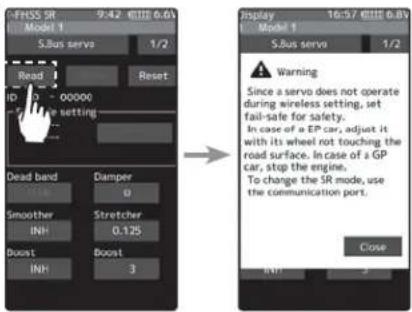
2 Touch the channel in which the servo to be set is connected and read the setting data from the servo.
- Communication port :T7PX communication port (conventional wired setting).
- Wireless 1 (Rx Ch1) :Receiver channel 1
- Wireless 2 (Rx Ch2) :Receiver channel 2
-"Reading succeeded" is displayed on the screen and the servo's ID cord and currently set contents are read.
- If "Failed" is displayed on the screen, communication with the servo is not being performed normally.
Check the T7PX and servo connection to servo and repeat [Read]. (Check receiver power supply etc.)
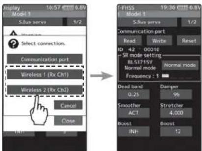
Other changes and additions
- Operation change in the "Acceleration" range (instruction manual page 60) within EPA setting range.
- Added poll number setting and gear ratio setting on Telemetry Link setting screen of non-Futaba sensor (Castle TL 0).
- Added support to change SR mode of BLS373SV.
Futaba has added a function to program your Futaba R334SBS / R334SBS-E receiver from the T7PX.
To update the receiver, you need a PC that can be connected to the Internet, a mini driver (to push the switch of the receiver), a micro SD card (commercial product), and a cord for CGY750 / GY701 / GY520 (optional) or DSC cord (optional).
Preparing for update
- Download the zip file of the update data from our website or your local distributor's website.
- Extract the zip file on your computer. A folder named "FUTABA" is created.
- Insert the micro SD card that contains the "FUTABA" folder into the T7PX (see page 31 of the manual).
Connection between T7PX and receiver

Turn on the DSP or PWR switch of T7PX and display the receiver update screen.
![graph TD A["Home screen"] --> B["Menu screen"] B --> C["System menu screen"] C --> D["Receiver update"] D --> E["Update"] style A fill:#f9f,stroke:#333 style B fill:#ccf,stroke:#333 style C fill:#cfc,stroke:#333 style D fill:#fcc,stroke:#333 style E fill:#cff,stroke:#333](/content/2026/07/1443791/images/d9ef339128449e044ed1ae64ddde143adc63933d4123537f452408a34bd94917.jpg)
Update method
1 Hold down the Link switch first, and turn ON the receiver.
After the LED flashes red once, release the Link switch and then press it again. As you continue holding down the Link switch, the LED starts flashing red and green. (Once flashing Red and Green, the initial process is complete.)
- If red and green do not turn on at the same time, please start over from the beginning.

2 Tap the "Update" button on the screen. The update will start. A progress bar will be displayed indicating the progress. The LED of the receiver turns green, and it blinks green for a moment every time it accepts data from the T7PX.
- Do not turn off the power of T7PX while updating.
3 When the update is completed, a message is displayed on the screen, and the LED of the receiver stays flashing green. Please turn off the power of the receiver.
Please check the operation before running (cruising).

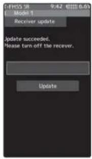
4 When finished, return to the System menu screen by pressing the HOME button.
Error
If an error display appeared, reinstall the update from the beginning.
- The receiver is not in the update wait state.
- The cable is disconnected.
- The power has been turned off
- The micro SD card is not inserted in the T7PX.
- There is no data on micro SD card.
Forced initialization
In the unlikely event that the model data is damaged and the T7PX stops working properly, it is possible to initialize the current model data in the following way.
Note:
This operation completely initializes the model data. Please do not use it except when data is broken.
How to Initialize
1 While pressing the PS6 switch, turn on the transmitter power.
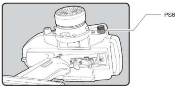
2 A confirmation screen, "Caution!! The current model data will be initialized. Sure?", will be displayed.
3 Touch [Yes] to carry out initialization and turn off the power. Since the current model data will be initialized, please re-set the data and check the operation carefully before use. To cancel the operation, touch [No]. The power is turned off without initializing the data.
- After initialization, the current model data will be initialized, so please set the data again before using and confirm the operation.


- IN NORTH AMERICA
- FOR SERVICE ONLY
- OUTSIDE NORTH AMERICA
- APPLICATION, EXPORT, AND MODIFICATION
- COMPLIANCE INFORMATION STATEMENT (FOR U.S.A.)
- CAUTION
- DECLARATION OF CONFORMITY (FOR EU)
- BATTERY RECYCLING (FOR U.S.A.)
- FOR YOUR SAFETY AS WELL AS THAT OF OTHERS ....8
- BEFORE USING 12
- CHANGING WHEEL POSITION AND MODIFYING FOR LEFT-HAND USE ..24
- INSTALLATION 32
- INITIAL SET-UP 36
- PREPARATIONS (TRANSMITTER) 36
- FUNCTION MAP 44
- MENU SELECTION ....44
- USER MENU 47
- FUNCTIONS ....52
- RECEIVER (TELEMETRY FUNCTION ON/OFF) 52
- CHANNEL REVERSE ....53
- SUB TRIM ....54
- END POINT ....55
- FAIL-SAFE/ BATTERY FAIL-SAFE ....58
- ACCELERATION....60
- TRIGGER 62
- SERVO VIEW 64
- D/R, ATL 65
- TRIM DIAL SELECT 66
- SWITCH SELECT 69
- IDLE-UP 72
- CHANNEL LIMITER 74
- CHANNEL SETTING ....75
- FOR YOUR SAFETY AS WELL AS THAT OF OTHERS
- BEFORE USING
- INSTALLATION
- INITIAL SET-UP
- FUNCTION MAP
- FUNCTIONS
- REFERENCE
- EXPLANATION OF SYMBOLS
- RECEIVER MODE PRECAUTIONS
- OPERATION PRECAUTIONS
- WARNING
- NIMH / NICD / LIFE BATTERY HANDLING PRECAUTIONS
- STORAGE AND DISPOSAL PRECAUTIONS
- OTHER PRECAUTIONS
- FEATURES
- FULL COLOR TOUCH SCREEN LCD
- T-FHSS SR(SUPER RESPONSE) & TELEMETRY T-FHSS
- UPDATEABLE SOFTWARE
- MODEL MEMORY FOR 40 MODELS
- NFC COMMUNICATION
- INTEGRAL TYPE DIAL SWITCH
- BRAKE MIXING FOR LARGE CARS
- STEERING MIXING
- 4WS MIXING FOR CRAWLERS AND OTHER 4WS TYPE
- DUAL ESCS MIXING FOR CRAWLERS
- GYRO MIXING
- TANK MIXING
- CPS MIXING
- S.BUS SERVO
- MC-LINK
- THROTTLE SPEED
- STEERING SPEED
- NON-TELEMETRY LED
- DIAL SELECT FUNCTION
- SWITCH SELECT FUNCTION
- WHEEL & TRIGGER POSITION CAN BE CHANGED
- TRIGGER BRAKE LEVER REPLACEMENT
- TRIM/DIAL LOCK FUNCTIONS
- LEFT-HANDED SUPPORT
- VIBRATOR BUILT INTO THE GRIP
- SET CONTENTS
- NOMENCLATURE
- BATTERY REPLACEMENT METHOD
- DISPOSAL OF THE DRY CELL BATTERIES
- LOW BATTERY ALARM
- WHEN USING THE OPTIONAL BATTERY
- CHARGING A NIMH BATTERY
- OVER CURRENT PROTECTION
- CHARGING A LIFE BATTERY
- WITH BALANCE CHARGER
- POWER & DISPLAY SWITCH
- POWER OFF FORGOTTEN ALARM & AUTO POWER OFF
- TRIM/DIAL LOCK
- SETTING
- CLEARING
- STEERING WHEEL AND THROTTLE TRIGGER OPERATION
- DIGITAL TRIM OPERATION
- STEERING AND THROTTLE TRIM OPERATION
- MECHANICAL ATL ADJUSTMENT
- ADJUSTMENT
- NOTE
- WHEEL & TRIGGER TENSION ADJUSTMENT
- TRIGGER SLIDE ADJUSTMENT & REMOVE THE HIGH POINT SPRING
- BRAKE LEVER REPLACEMENT
- CHANGING WHEEL POSITION AND MODIFYING FOR LEFT-HAND USE
- CHANGING THE WHEEL POSITION
- MODIFYING FOR LEFT-HAND USE
- ANGLE CAN BE ADJUSTED
- THE OPERATING ANGLE OF THE WHEEL CAN BE ADJUSTED
- EXCHANGE PROCEDURE TO WHEEL ADAPTOR 32 DEG AND LARGE DIAMETER WHEEL
- INSTALLING THE ACCESSORY APA STEERING WHEEL OFFSET ADAPTER
- 1 REMOVE THE 2 STEERING WHEEL UNIT MOUNTING SCREWS (3.0X12MM CAP SCREW)
- 2 GENTLY REMOVE THE STEERING UNIT, WITHOUT PULLING EXCESSIVELY ON THE WIRING
- 3 REMOVE THE 3 CONNECTORS FROM THE PC BOARD
- 4 USING A PHILLIPS SCREWDRIVER, REMOVE THE 4 SCREWS (2.6X15MM TAPPING SCREW) MOUNTING THE WHEEL UNIT AND SWITCH UNIT
- NON-TELEMETRY LED (TELEMETRY OFF SIGN)
- HANDLING THE ANTENNA AND CARD SLOT AND RECEIVER
- ABOUT THE TRANSMITTER ANTENNA
- ANTENNA MOVING RANGE
- RECEIVER TERMINOLOGY
- CONNECTORS
- RECEIVER INSTALLATION
- HANDLING A MICROSD CARD (COMMERCIAL PRODUCT)
- (COMMERCIAL PRODUCT)
- RECEIVER AND SERVO CONNECTIONS
- INSTALLATION SAFETY PRECAUTIONS
- RECEIVER (RECEIVER ANTENNA)
- RECEIVER VIBRATION-PROOFING / WATERPROOFING
- (CAR)
- (BOAT)
- CONNECTOR CONNECTIONS
- SERVO INSTALLATION
- SERVO THROW
- ELECTRONIC SPEED CONT
- MOTOR NOISE SUPPRESSION
- OTHER NOISE SUPPRESSION METHODS
- PREPARATIONS (TRANSMITTER)
- (DISPLAY WHEN POWER SWITCH TURNED ON)
- RF OUTPUT & RX TYPE CHECK
- RECEIVER SYSTEM CHANGE & HOW TO LINK
- RECEIVERS OTHER THAN T-FHSS
- PRECAUTION
- HOW TO SET THE RESPONSE / SR MODE
- SERVO CONFORMING TO THE SETTING OF RESPONSE / SR MODE
- TRIGGER RATIO CHECK
- TRIMS INITIAL SET-UP
- STEERING TRIM (DT1) CHECK
- THROTTLE TRIM (DT2) CHECK
- STEERING DUAL RATE (DT5) CHECK
- BRAKE RATE (DT6) CHECK
- MENU SELECTION
- DISPLAY MENU SCREEN
- HOME BUTTON SETTING
- VALUE OF EACH FUNCTION AND CHANGING THE SET VALUE
- USER MENU
- DISPLAYING AND EDITING THE USER MENU SCREEN
- MENU ASSIGNMENT
- RECEIVER
- TELEMETRY FUNCTION ON/OFF
- CHANNEL REVERSE
- SERVO REVERSE FUNCTION SETTING
- SUB TRIM
- SUB TRIM ADJUSTMENT
- (PREPARATION)
- ADJUSTMENT BUTTONS
- 1 (SUB TRIM ADJUSTMENT)
- END POINT
- MAXIMUM STEERING ANGLE
- BRAKE RATE TRIM
- ⚠ WARNING
- STEERING END POINT ADJUSTMENT
- QUICK EPA
- THROTTLE END POINT ADJUSTMENT
- 1 THROTTLE (FORWARD SIDE) ADJUSTMENT
- AUXILIARY CHANNEL SERVO END POINT ADJUSTMENT
- SPARE CHANNEL DISPLAY
- FAIL-SAFE/ BATTERY FAIL-SAFE
- FAIL SAFE MODE
- HOLD MODE
- OFF MODE (OFF)
- BATTERY FAIL SAFE FUNCTION (B-F/S)
- FAIL SAFE MODE SELECTION
- FAIL SAFE FUNCTION SETUP
- B-F/S FUNCTION ON/OFF & BATTERY FAIL-SAFE VOLTAGE SETTING
- ACCELERATION
- OPERATION
- SET VALUE
- CONVENIENT USAGE METHOD
- THROTTLE ACCELERATION ADJUSTMENT
- FORWARD ACCELERATION AMOUNT (FORWARD)
- BRAKE SIDE ACCELERATION AMOUNT (BRAKE1)
- DIAL / TRIM SETTING
- TRIGGER
- THROTTLE SERVO NEUTRAL POSITION "RATIO
- SELECTING THE TRIGGER RATIO
- NEUTRAL BRAKE FUNCTION ADJUSTMENT
- 1 (NEUTRAL BRAKE RATE)
- ADJUST BUTTON
- NEUTRAL BRAKE
- 2 WHEN FI NISHED, RETURN TO THE LINKAGE MENU SCREEN BY PRESSING THE HOME BUTTON
- EFFECT OF SET VALUE OF OTHER FUNCTIONS ON NEUTRAL BRAKE
- SERVO VIEW
- CONFIR RM OPERATION
- D/R, ATL
- D/R (STEERING DUAL RATE)
- ATL (BRAKE 1 RATE)
- DUAL RATE ADJUSTMENT
- BRAKE RATE (ATL) ADJUSTMENT
- DUAL RATE
- BRAKE RATE(ATL)
- TRIM / DIAL SELECT
- FUNCTION SELECT DIAL SETUP
- 3 WHEN FINISHED, RETURN TO THE LINKAGE MENU SCREEN BY PRESSING THE HOME BUTTON
- RELATIONSHIP BETWEEN SET VALUE AND STEP AMOUNT
- SWITCH SELECT
- 1 (FUNCTION SETUP)
- THE HOME SCREEN DISPLAY
- IDLE-UP
- IDLE-UP FUNCTION ADJUSTMENT
- 1 (IDLE-UP RATE)
- IDLE-UP RATE
- 2 WHEN FINISHED, RETURN TO THE LINKAGE MENU SCREEN BY PRESSING THE HOME BUTTON
- CHANNEL LIMITER
- CHANNEL LIMITER ADJUSTMENT
- LIMITER RATE
- CHANNEL SETTING
- HOW TO SELECT STEERING / THROTTLE
- 1 (CHANNEL SETUP)
- 2 (POSITION SETTING OF AUXILIARY CHANNEL)
- POSITION
- 3 WHEN FI NISHED, RETURN TO THE LINKAGE MENU SCREEN BY PRESSING THE HOME BUTTON
- CONDITION
- CONDITION ADJUSTMENT
- 1 (FUNCTION ON/OFF)
- 2 (CONDITION COPY)
- DISPLAY WHEN USING CONDITION
- CURVE (EXP)
- STEERING CURVE
- STEERING EXP ADJUSTMENT
- CURVE RATE
- STEERING VTR ADJUSTMENT
- 2 CURVE SWITCHING POINT ADJUSTMENT
- THROTTLE CURVE (FORWARD SIDE)
- ADVICE
- ADJUSTMENT METHOD FOR EXP CURVE
- THROTTLE VTR ADJUSTMENT
- ADJUSTMENT METHOD FOR CURVE
- POINT
- SCREEN SWITCHING BETWEEN THROTTLE FORWARD SIDE CURVE AND BRAKE SIDE CURVE
- BRAKE CURVE
- SPEED
- STEERING SPEED ADJUSTMENT
- 1 ("TURN" DIRECTION DELAY ADJUSTMENT)
- 2 ("RETURN" DIRECTION ADJUSTMENT)
- SPEED RANGE
- 3 WHEN FINISHED, RETURN TO THE RACING MENU SCREEN BY PRESSING THE HOME BUTTON TWICE
- ADJUSTMENT METHOD FOR 1 SPEED
- 2 ("ALL" RETURN DIRECTION DELAY ADJUSTMENT)
- ADJUSTMENT METHOD FOR 2 SPEED
- 1 ("LOW" AND "HIGH" TURN DIRECTION DELAY ADJUSTMENT)
- 2 ("LOW" AND "HIGH" RETURN DIRECTION DELAY ADJUSTMENT)
- 3 (SPEED SWITCHING POINT ADJUSTMENT)
- 4 WHEN FINISHED, RETURN TO THE RACING MENU SCREEN BY PRESSING THE HOME BUTTON TWICE
- ADJUSTMENT METHOD FOR 3 SPEED
- 1 ("LOW", "MIDDLE", OR "HIGH" TURN DIRECTION DELAY ADJUSTMENT)
- 2 ("LOW", MIDDLE", AND "HIGH" RETURN DIRECTION DELAY ADJUSTMENT)
- A.B.S
- MODE : FUNCTION ON/OFF
- BRAKE RETURN
- DELAY
- CYCLE SPEED
- DUTY RATIO
- TRIGGER POINT
- WHEN TRIGGER RATIO WAS SET TO 100:0
- A.B.S. FUNCTION ADJUSTMENT
- 1
- 2
- RETURN AMOUNT
- 3 ("DELAY" AMOUNT SETUP)
- 4 ("CYCLE SPEED" ADJUSTMENT)
- 5 ("DUTY RATIO" SETUP)
- DELAY AMOUNT
- CYCLE SPEED AMOUNT
- DUTY RATIO AMOUNT
- 6
- 7
- 1/5 SCALE CAR AND OTHER INDEPENDENT BRAKES AND ABS
- SWITCH SETTING
- EXAMPLE OF A.B.S. FUNCTION SETTING WHEN S9373SV USED
- TRACTION CONTROL
- THROTTLE RETURN
- TRACTION CONTROL FUNCTION ADJUSTMENT
- 2 ("THROTTLE RETURN" AMOUNT ADJUSTMENT)
- 6 ("TRIGGER POINT" SETUP)
- START
- START FUNCTION ADJUSTMENT
- 2 ("TRIGGER POINT" SETUP)
- 3 ("PRESET POSITION" SETUP)
- PRESET POSITION
- 4 ("READY" SETTING)
- RESTART
- 5 WHEN FINISHED, RETURN TO THE RACING MENU SCREEN BY PRESSING THE HOME BUTTON
- ENGINE CUT
- ENGINE CUT FUNCTION ADJUSTMENT
- 1 (PRESET POSITION SETUP)
- STEERING MIXING ADJUSTMENT
- 2 (CHANNEL SETUP)
- 3 (STEERING 1 SERVO STEERING ANGLE ADJUSTMENT)
- STEERING 1 RATE (LEFT/RIGHT) 0\~140
- 4 (STEERING 2 SERVO STEERING ANGLE ADJUSTMENT)
- STEERING 2 RATE (LEFT/RIGHT) 0\~140
- 5 (STEERING MIXING RATE ADJUSTMENT)
- STEERING MIX RATE
- 6 (ACKERMAN ADJUSTMENT)
- 7 (STEERING BRAKE)
- BRAKE RATE
- 8 WHEN FINISHED, RETURN TO THE RACING MENU SCREEN BY PRESSING THE HOME BUTTON TWICE
- BRAKE MIXING
- AUXILIARY CHANNELS A.B.S
- 3 (BRAKE 2 & 3 RATE)
- 4 (DELAY AMOUNT SETUP)
- 5 (STEERING MIXING)
- BRAKE RATE (MIXING)
- AVCS / NORMAL MODES
- GYRO MIXING ADJUSTMENT
- 3 (GYRO MIXING TYPE SELECTION)
- 4 (GYRO GAIN ADJUSTMENT)
- GYRO GAIN
- 5 WHEN FI NISHED, RETURN TO THE MIXING MENU SCREEN BY PRESSING THE HOME BUTTON TWICE
- 4WS MIXING
- 4WS MIXING ADJUSTMENT
- 3 (4WS TYPE SELECTION)
- 4 (REAR SIDE TRAVEL ADJUSTMENT)
- REAR RATE (REAR MIX RATE)
- 5 (MIX MODE SETTING)
- 6 WHEN FINISHED, RETURN TO THE MIXING MENU SCREEN BY PRESSING THE HOME BUTTON TWICE
- DUAL ESC
- DUAL ESC MIXING ADJUSTMENT
- 3 (DRIVE RATIO ADJUSTMENT)
- 4 (MIX MODE SETTING)
- 5 (TRIM MODE SETUP)
- 6 WHEN FI NISHED, RETURN TO THE MIXING MENU SCREEN BY PRESSING THE HOME BUTTON TWICE
- CPS MIXING (1, 2, 3)
- 3 (CONTROL SYSTEM SETUP)
- 4 (ON / OFF SWITCHING POSITION SELECTION)
- 5 (OPERATION MODE SETUP)
- 6 (FLASHING CYCLE SETTING)
- ON/OFF POSITION
- CYCLE SPEED AMOUNT 1\~100
- 7 WHEN FINISHED, RETURN TO THE MIXING MENU SCREEN BY PRESSING THE HOME BUTTON TWICE
- TANK MIXING ADJUSTMENT
- 2 (LIMIT ON / OFF)
- 3 (FORWARD / BACKWARD RATE ADJUSTMENT)
- FORWARD / BACKWARD RATE
- 4 (LEFT / RIGHT SIDE TRAVEL ADJUST)
- LEFT / RIGHT TRAVEL
- 5 WHEN FINISHED, RETURN TO THE MIXING MENU SCREEN BY PRESSING THE HOME BUTTON TWICE
- WHEN STEERING AND TRIGGER ARE OPERATED AT THE SAME TIME
- PROGRAM MIXING (1, 2, 3, 4, 5)
- ADDITIONAL FUNCTIONS
- MOVEMENT OF THE SLAVE CHANNEL SIDE
- PROGRAM COMPOSITE ADJUSTMENT
- 2 (MASTER / SLAVE CHANNEL SETUP)
- 3 (MIX MODE SETTING)
- 4 (TRIM MODE SETUP)
- 5 (LEFT, FORWARD OR A SIDE MIXING AMOUNT ADJUSTMENT)
- 6 (RIGHT, BRAKE OR B SIDE MIXING AMOUNT ADJUSTMENT)
- 7 (CURVE SETTING)
- 8 WHEN FINISHED, RETURN TO THE MIXING MENU SCREEN BY PRESSING THE HOME BUTTON TWICE
- TILT MIXING
- EFFECT OF THE SET VALUE OF OTHER FUNCTIONS ON TILT MIXING
- TILT MIXING ADJUSTMENT
- 3 (FLAP RATE CHECK AND ADJUSTMENT)
- 4 (RUDDER TO FLAP MIXING AMOUNT ADJUSTMENT)
- 5 (FLAP TO RUDDER MIXING AMOUNT ADJUSTMENT)
- MIXING AMOUNT (RUDDER TO FLAP)
- MIXING AMOUNT (FLAP TO RUDDER)
- TIMER
- UP TIMER FUNCTION
- FUEL DOWN TIMER FUNCTION
- LAP TIMER FUNCTION
- (LAP TIMER OPERATION)
- LAP NAVIGATE TIMER FUNCTION
- RACING TIMER TYPE SELECTION
- USING THE UP TIMER
- 1 (ALARM TIME SETTING)
- ALARM TIME
- PRE-ALARM TIME
- GRIP VIBRATOR TYPE (PATTERN)
- 2 (TIMER START/STOP OPERATION)
- START / STOP
- 3 (TIMER RESET OPERATION)
- TIMER RESET
- USING THE FUEL DOWN TIMER
- USING THE LAP TIMER
- 2 (TIMER START OPERATION)
- 3 (TIMER STOP AND LAP RESET OPERATION)
- USING THE LAP NAVIGATE TIMER
- LAP NAVI TIME
- 2 (TIMER START / NAVIGATION RESTART OPERATION)
- 3 (TIMER STOP / RESET OPERATION)
- LAP LIST
- USING THE LAP MEMORY
- USING THE S.BUS SERVO FUNCTION
- DISPLAY DATA LIST
- SR MODE SETTING
- S.BUS FUNCTION SETUP
- ID
- DEAD BAND
- DAMPER
- SMOOTHER
- STRETCHER
- BOOST/ BOOST (ON/OFF)
- CHANNEL
- REVERSE
- SOFT START
- NEUTRAL
- STOP MODE
- TRAVEL [LEFT] / [RIGHT]
- MC (ESC) LINK
- USING THE ESC LINK FUNCTION
- PWM FREQUENCY (MIN)
- PWM FREQUENCY (MAX)
- PWM FREQUENCY (BRAKE)
- LOW BATTERY PROTECTION
- CURRENT LIMITER
- CURRENT LIMITER INH/ACT SETTING
- CURRENT LIMIT TIMER
- CURRENT LIMITER (TIME)
- BRAKE MAX. DUTY
- REVERSE MAX. DUTY
- REVERSE MODE SHIFT LEVEL
- FORWARD BOOST
- REVERSE CANCEL
- ROBOT MODE
- BRAKE SLOPE
- BRAKE TIMER
- LEAD ANGLE
- BEC VOLTAGE
- TURBO MODE
- MC940,960CR/ :TURBO0/TURBO1/TURBO2
- TURBO0 MODE: (NO LEAD ANGLE MODE) LEAD ANGLE - NO
- TURBO1 TURBO MODE: (LEAD ANGLE MODE) LEAD ANGLE – YES
- TURBO2 POWER MODE: (POWER MODE) LEAD ANGLE – YES
- POWER POINT A
- LEAD ANGLE USE
- POINT A,B,C,D,E LEAD ANGLE
- POINT A,B,C,D,E ROTATION
- ROLL OUT CHART
- USE OF ROLL OUT CHART FUNCTION
- GEAR RATIO CHART
- HOW TO SET THE HOME BUTTON
- 1 (SETTING FOR PUSH)
- 2 (SETTING FOR LONG PRESS)
- 3 WHEN FINISHED, RETURN TO THE ACCESSORY MENU SCREEN BY PRESSING THE HOME BUTTON
- TELEMETRY SYSTEM
- TELEMETRY
- USING TELEMETRY FUNCTION
- TELEMETRY: RECEIVER BATTERY VOLTAGE
- ALARM AND VIBRATOR FUNCTION SETUP
- 1 (LIMIT ADJUSTMENT)
- 2 (ALARM FUNCTION SETUP)
- 3 (VIBRATOR FUNCTION SETUP)
- 4 (SPEECH FUNCTION SETUP)
- 5 WHEN FI NISHED, RETURN TO THE TELEMETRY SCREEN BY PRESSING THE HOME BUTTON
- TELEMETRY: THE DRIVE BATTERY VOLTAGE
- TELEMETRY: RPM
- 1 (GEAR RATIO ADJUSTMENT)
- 2 (LIMIT ADJUSTMENT)
- 3 (ALARM AND VIBRATOR FUNCTION SETUP)
- TELEMETRY: TEMPERATURE
- 2 (ALARM AND VIBRATOR FUNCTION SETUP)
- 3 (SPEECH FUNCTION SETUP)
- 4 WHEN FINISHED, RETURN TO THE TELEMETRY SCREEN BY PRESSING THE HOME BUTTON
- TELEMETRY: THE DRIVE BATTERY ELECTRIC CURRENT
- UPPER SIDE
- LOWER
- RESET CONSUMPTION CAPACITY DISPLAY
- 1 (RESET OPERATION)
- 2 WHEN FINISHED, RETURN TO THE TELEMETRY SCREEN BY PRESSING THE HOME BUTTON
- TELEMETRY: GPS
- HOW TO SET THE REFERENCE POSITION
- SENSOR LIST
- WHAT IS A SLOT
- ABOUT THE SLOTS THAT CAN BE USED
- HOW TO CHANGE START SLOT AND SET EMPTY SLOT
- 1 (START SLOT SELECTION)
- 2 (SENSOR SELECTION)
- SENSOR
- SENSOR RELOAD
- 2 WHEN FI NISHED, RETURN TO THE TELEMETRY SCREEN BY PRESSING THE HOME BUTTON
- SENSOR REGISTER
- CHANGE SLOT
- SENSOR SLOT CHANGE
- 1 (CHANGE)
- 2 (NUMBER SETTING)
- 3 TAP THE [WRITE]. WHEN "WRITING SUCCEEDED" MESSAGE IS DISPLAYED, THE NUMBER CHANGE IS COMPLETED
- 4 WHEN FINISHED, RETURN TO THE SENSOR SCREEN BY PRESSING THE HOME BUTTON
- SPEECH GUIDE INTERVAL AND LOG DATA INTERVAL SETTING
- SETTING INTERVAL
- 1 (SETTING OF SPEECH INTERVAL)
- SPEECH INTERVAL
- 2 (SETTING OF LOGGING INTERVAL)
- LOGGING INTERVAL
- TELEMETRY METER DISPLAY ON HOME SCREEN
- DISPLAY OF TELEMETRY METER
- TELEMETRY METER DISPLAY SETTINGS
- MODEL SELECT
- USING THE MODEL SELECTION FUNCTION
- 1 (MODEL MEMORY SELECTION)
- 2 (MODEL SELECTION EXECUTION
- 3 WHEN FI NISHED, RETURN TO THE MODEL MENU SCREEN BY PRESSING THE HOME BUTTON
- MODEL COPY
- MODEL COPYING
- 1 (COPY SOURCE MODEL SELECTION)
- 3 (COPY DESTINATION MODEL SELECTION)
- 4 (COPY EXECUTION)
- MICROSD CARD STORAGE DESTINATION
- MODEL NAME
- SETTING THE MODEL NAME AND USER NAME
- NAME CURSOR MOVEMENT
- SELECT / DETERMINE CHARACTER
- MODEL DELETE (MODEL SAVED ON MICROSD CARD)
- HOW TO DELETE MODEL DATA IN MICROSD CARD
- 1 (SELECTION OF MODEL DATA)
- 2 (EXECUTION OF MODEL DELETION)
- 3 WHEN FINISHED, RETURN TO THE MODEL MENU SCREEN BY PRESSING THE HOME BUTTON
- DATA RESET
- DISPLAY
- DISPLAY SETUP
- 4 (TOUCH PANEL SENSITIVITY ADJUSTMENT)
- 5 (TOUCH PANEL VIBRATE ON / OFF)
- 6 (SETTING OF START / END SCREEN)
- 7 WHEN FINISHED, RETURN TO THE SYSTEM MENU SCREEN BY PRESSING THE HOME BUTTON
- SENSITIVITY
- INFORMATION
- SETTING THE USER NAME
- LANGUAGE SETTING
- 1 (LANGUAGE SELECT)
- UNITS SYSTEM SETTING
- 1 (UNITS SYSTEM SETTING)
- DISPLAY OF MANUFACTURER INFORMATION AND OPEN SOURCE LICENSE
- 1 (SHOW THE MANUFACTURER INFORMATION AND OPEN SOURCE LICENSE)
- 3 WHEN FINISHED, RETURN TO THE SYSTEM MENU SCREEN BY PRESSING THE HOME BUTTON
- SOUND
- VOLUME ADJUSTMENT
- BATTERY
- BATTERY SETTING
- DATA AND TIME
- DATE AND TIME SETTING
- LED SETTING
- 1 (SETTING PILOT LED)
- PILOT LED MODE
- 2 (SETTING PILOT LED BRIGHTNESS)
- BRIGHTNESS
- CALIBRATION
- STEERING ADJUSTMENT
- THROTTLE ADJUSTMENT
- SOFTWARE UPDATE
- SPECIFICATIONS
- TRANSMITTER T7PX
- RECEIVER R334SBS / : (T-FHSS SR /T-FHSS SYSTEM, 4 CHANNELS)
- PARAMETER BY TYPE OF SERVO FOR SR MODE
- SYSTEM COMPATIBILITY
- WARNING DISPLAYS
- POWER OFF FORGOTTEN ALARM
- AUDIBLE ALARM: CONTINUOUS TONE
- MIX WARNING
- RF ERROR
- BACKUP ERROR
- SYSTEM ERROR
- T7PX SCREEN PROTECTOR
- HOW TO ATTACH THE PROTECTOR
- OPTIONAL PARTS
- TRANSMITTER BATTERY
- PART NAME
- TELEMETRY SENSORS
- T7PX / T4PX ANGLE SPACER
- T7PX / T4PX LARGE GRIP (FOR TRANSMITTER)
- CARBON HANDLE (FOR TRANSMITTER)
- WHEN REQUESTING REPAIR
- (INFORMATION NEEDED FOR REPAIR)
- (WARRANTY)
- 7PX
- 7PX TELEMETRY SYSTEM
- T7PX SOFTWARE UPDATE METHOD
- PROCEDURE FOR THE SOFTWARE UPDATE
- POSSIBLE PROBLEMS
- LOW BATTERY
- UPDATE FILE NOT FOUND
- BROKEN FILE
- WRITE ERROR
- HOW TO CHECK THE RECEIVER SOFTWARE VERSION
- CONNECTION CHANNEL OF SERVO TO MAKE WIRELESS SETTING
- HOW TO USE WIRELESS SETTINGS
- OTHER CHANGES AND ADDITIONS
- PREPARING FOR UPDATE
- UPDATE METHOD
- ERROR
- FORCED INITIALIZATION
- HOW TO INITIALIZE
Brand : FUTABA
Model : 7PX
Category : Remote control toy