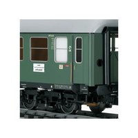
58024 - Model making Märklin - Free user manual and instructions
Find the device manual for free 58024 Märklin in PDF.


| Product type | Model train |
| Brand | Märklin |
| Model | 58024 |
| Category | Scale modeling |
| Scale | H0 (1:87) |
| Track gauge | 16.5 mm |
| Power system | Alternating current 14–16 V |
| Control type | Analog (digital compatible with decoder) |
| Locomotive dimensions | Approximately 200 × 40 × 60 mm |
| Weight | Approximately 0.5 kg |
| Materials | Metal and plastic |
| Main functions | Front/rear lighting, forward/reverse, coupling |
| Lighting | LED or bulb, switchable |
| Decoder | Interface for digital decoder (not included) |
| Maintenance | Regular cleaning of wheels and contacts |
| Cleaning | Soft dry cloth, avoid solvents |
| Safety | Do not use on non-compliant track, keep out of reach of children under 3 years |
| Recommended age | 14 years and older |
| Spare parts | Available from the manufacturer or authorized dealers |
| Warranty | 2 years |
Frequently Asked Questions - 58024 Märklin
User questions about 58024 Märklin
0 question about this device. Answer the ones you know or ask your own.
Ask a new question about this device
Download the instructions for your Model making in PDF format for free! Find your manual 58024 - Märklin and take your electronic device back in hand. On this page are published all the documents necessary for the use of your device. 58024 by Märklin.
USER MANUAL 58024 Märklin
Vierachsiger Personenwagen
58013, 58023, 58024, 58043, 58053
Table of Contents Page
Technical Information 9
Minimum radius require for operation 9
Coupler System 10
Lighting 11
Conversion of the circuit board for the lighting 12
Inhoudsopgave Blz.
Minimum radius require for operation: 1,020 mm / 40-3/16"
Minimum spacing for two parallel tracks with the minimum radius at 1,020 mm / 40-3/16": 149 mm / 5-7/8".
If the spacing is too small, these cars can sideswipe each other or other cars and locomotives on curves an thus cause damage to these cars!


Coupler System
Close coupler with guide mechanism. Coupler head compatible with the Märklin claw coupler.
Important: The warranty for these cars becomes null and void if other makes of couplers are used with them.
Special reproduction prototype couplers are included with these cars if the latter are to be put on display. These reproduction prototype couplers are not intended for use on these cars if the latter are to be run in trains. These couplers cannot be used for operation on märklin track.
![graph TD A["Step 1: Tool Insert"] --> B["Step 2: Cut"] B --> C["Step 3: Screw"] C --> D["Step 4: Spring Clamp"] D --> E["Step 5: Screw"] style A fill:#f9f,stroke:#333 style B fill:#ccf,stroke:#333 style C fill:#cfc,stroke:#333 style D fill:#fcc,stroke:#333 style E fill:#ffc,stroke:#333](/content/2026/07/1454074/images/9f8e7717cb7581afb17da2b3c806259bdf7cdb0cf4b6e4cfc8bb9f615bbc6002.jpg)
Lighting
These cars have built-in LED lighting that has been installed at the factory. This LED lighting consumes very little power and is therefore suitable for digital or Delta operation. In conventional operation (AC or DC power) this lighting does not begin to work until the cars are being pulled at fairly high speeds by a locomotive.
Important:
All of the wheel sets on these cars are used for providing power to the ligths. The wheels for both trucks are therefore electrically connected with each other. Insulated track joints (for signal blocks, etc.) will be bridged by these trucks. It may happen that a train will run through a signal block, where the power has been shut off by a signal set for stop, if these cars are in the train.
These cars can be used with the 72441/72442 brake module only if the first transition area is the length of the entire train (!), not the length of the longest locomotive. A transition area that is too short may lead to the destruction of the Control Unit!
Conversion of the circuit board for the lighting
The circuit board for the lighting is ready for the installation of a function decoder. With this decoder the lights in either half of the car's corridor or in half of the compartments can be turned on separately in digital operation.
With the half dining car (example: 58043) or the half baggage car (example: 58053) the quantity of LED's turned on is influenced by the different functions. It is not possible in these cars to separate the lights turned on into particular function areas as with the compartment cars.
1. Remove the car roof
Important: The roof has several very rigid snap-in connections. A certain amount of force is therefore necessary to remove the roof.

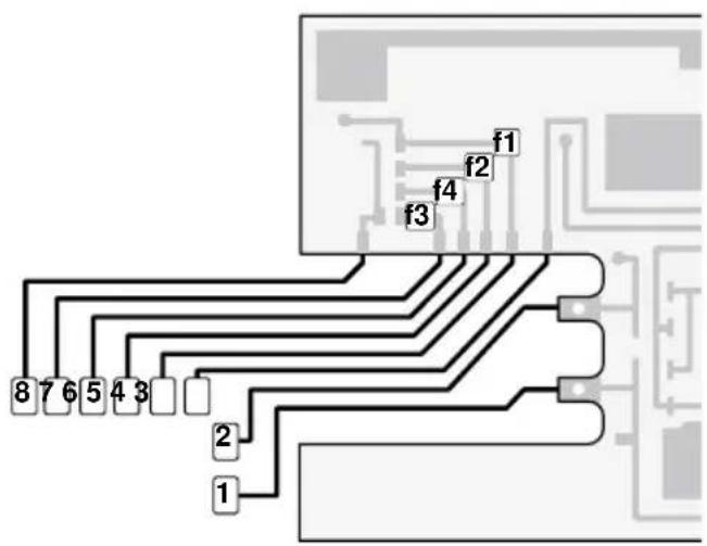
2. Cut the conductors 3. Install the decoder

1 brown 0
2 red B
3 orange +
4 brown/red f1
5 brown/green f2
6 brown/white f3
7 brown/yellow f4
8 violet GND
f1 Lighting in the car corridor on the left side
f2 Lighting in the car corridor on the right side
f3 Lighting in the compartments on the left side
f4 Lighting in the compartments on the right side
Please note the directions for the coding switches on the function decoder in the instructions that come with this unit.

Koppelingssysteem
1 bruin 0
2 rood B
3 orange +
4 bruin/rood f1
5 bruin/groen f2
6 bruin/wit f3
7 bruin/geel f4
8 paars GND
Due to different legal requirements regarding electro-magnetic compatibility, this item may be used in the USA only after separate certification for FCC compliance and an adjustment if necessary. Use in the USA without this certification is not permitted and absolves us of any liability. If you should want such certification to be done, please contact us – also due to the additional costs incurred for this.

Brand : Märklin
Model : 58024
Category : Model making