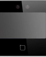
R71CF-312 - Security System ACTi - Free user manual and instructions
Find the device manual for free R71CF-312 ACTi in PDF.


| Product Type | IP Security Camera |
| Brand | ACTi |
| Model | R71CF-312 |
| Image Sensor | 1/2.8" Progressive Scan CMOS |
| Resolution | 2 Megapixel (1920 x 1080) |
| Lens | Fixed 2.8mm |
| Night Vision | Up to 30 meters IR |
| Power Supply | PoE (802.3af) or DC 12V |
| Power Consumption | Max 8W |
| Dimensions (Ø x H) | 110 mm x 90 mm |
| Weight | 0.45 kg |
| Ingress Protection | IP66 |
| Operating Temperature | -30°C to 50°C |
| Video Compression | H.265, H.264, MJPEG |
| Main Functions | Motion detection, tampering alarm, privacy masking |
| Storage | MicroSD slot up to 128GB |
| Network | RJ45 10/100 Mbps |
| Maintenance | Clean dome with soft dry cloth; check cable connections |
| Safety | Surge protection, reverse polarity protection |
| Spare Parts | Replacement dome cover, mounting bracket |
| Repairability | Modular design with replaceable IR board and lens assembly |
| General Information | Indoor/outdoor use; supports ONVIF Profile G |
Frequently Asked Questions - R71CF-312 ACTi
User questions about R71CF-312 ACTi
0 question about this device. Answer the ones you know or ask your own.
Ask a new question about this device
Download the instructions for your Security System in PDF format for free! Find your manual R71CF-312 - ACTi and take your electronic device back in hand. On this page are published all the documents necessary for the use of your device. R71CF-312 by ACTi.
USER MANUAL R71CF-312 ACTi
Face Recognition Reader & Controller
User's Manual
R71CF-311
R71CF-312
2024/05/16
Regulatory Information
FCC Information
Please take attention that changes or modification not expressly approved by the party responsible for compliance could void the user's authority to operate the equipment.
FCC compliance: This equipment has been tested and found to comply with the limits for a Class B digital device, pursuant to part 15 of the FCC Rules. These limits are designed to provide reasonable protection against harmful interference in a residential installation. This equipment generates, uses and can radiate radio frequency energy and, if not installed and used in accordance with the instructions, may cause harmful interference to radio communications.
However, there is no guarantee that interference will not occur in a particular installation. If this equipment does cause harmful interference to radio or television reception, which can be determined by turning the equipment off and on, the user is encouraged to try to correct the interference by one or more of the following measures:
—Reorient or relocate the receiving antenna.
—Increase the separation between the equipment and receiver.
—Connect the equipment into an outlet on a circuit different from that to which the receiver is connected.
—Consult the dealer or an experienced radio/TV technician for help
This equipment should be installed and operated with a minimum distance 20cm between the radiator and your body.
FCC Conditions
This device complies with part 15 of the FCC Rules. Operation is subject to the following two conditions:
- This device may not cause harmful interference.
- This device must accept any interference received, including interference that may cause undesired operation.
Now that the camera and the PC are both having their unique IP addresses and are under the same network segment, it is possible to use the Web browser of the PC to access the camera.
EU Conformity Statement

This product and - if applicable - the supplied accessories too are marked with "CE" and comply therefore with the applicable harmonized European standards listed under the EMC Directive 2014/30/EU, RE Directive 2014/53/EU, the RoHS Directive 2011/65/EU

2012/19/EU (WEEE directive): Products marked with this symbol cannot be disposed of as unsorted municipal waste in the European Union. For proper recycling, return this product to your local supplier upon the purchase of equivalent new equipment, or dispose of it at designated collection points. For more information see: www.recyclethis.info
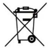
2006/66/EC (battery directive): This product contains a battery that cannot be disposed of as unsorted municipal waste in the European Union. See the product documentation for specific battery information. The battery is marked with this symbol, which may include lettering to indicate cadmium (Cd), lead (Pb), or mercury (Hg). For proper recycling, return the battery to your supplier or to a designated collection point. For more information see:www.recyclethis.info
This device complies with Industry Canada licence-exempt RSS standard(s). Operation is subject to the following two conditions:
(1) this device may not cause interference, and
(2) this device must accept any interference, including interference that may cause undesired operation of the device.
These instructions are intended to ensure that user can use the product correctly to avoid danger or property loss.
The precaution measure is divided into Dangers and Cautions:
Dangers: Neglecting any of the warnings may cause serious injury or death. Follow these safeguards to prevent serious injury or death.
Cautions: Neglecting any of the cautions may cause injury or equipment damage. Follow these precautions to prevent potential injury or material damage.
⚠️Danger:
- All the electronic operation should be strictly compliance with the electrical safety regulations, fire prevention regulations and other related regulations in your local region.
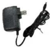
- Please use the power adapter, which is provided by normal company. The power consumption cannot be less than the required value.
- Do not connect several devices to one power adapter as adapter overload may cause over-heat or fire hazard.
- Please make sure that the power has been disconnected before you wire, install or dismantle the device.
- When the product is installed on wall or ceiling, the device shall be firmly fixed.
- If smoke, odors or noise rise from the device, turn off the power at once and unplug the power cable, and then please contact the service center.
- Risk of explosion if the battery is replaced by an incorrect type
- Improper replacement of the battery with an incorrect type may defeat a safeguard (for example, in the case of some lithium battery types).
- This equipment is not suitable for use in locations where children are likely to be present.
- Do not dispose of the battery into fire or a hot oven, or mechanically crush or cut the battery, which may result in an explosion.
- Do not leave the battery in an extremely high temperature surrounding environment, which may result in an explosion or the leakage of flammable liquid or gas.
- Do not subject the battery to extremely low air pressure, which may result in an explosion or the leakage of flammable liquid or gas.
- Dispose of used batteries according to the instructions
- If the product does not work properly, please contact your dealer or the nearest service center. Never attempt to disassemble the device yourself. (We shall not assume any responsibility for problems caused by unauthorized repair or maintenance.)
⚠️ Cautions:
- Do not drop the device or subject it to physical shock, and do not expose it to high electromagnetism radiation. Avoid the equipment installation on vibrations surface or places subject to shock (ignorance can cause equipment damage).
- Do not place the device in extremely hot (refer to the specification of the device for the detailed operating temperature), cold, dusty or damp locations, and do not expose it to high electromagnetic radiation.
- The device cover for indoor use shall be kept from rain and moisture.
- Exposing the equipment to direct sun light, low ventilation or heat source such as heater or radiator is forbidden (ignorance can cause fire danger).
- Do not aim the device at the sun or extra bright places. A blooming or smear may occur otherwise (which is not a malfunction however), and affecting the endurance of sensor at the same time.
- Please use the provided glove when open up the device cover, avoid direct contact with the device cover, because the acidic sweat of the fingers may erode the surface coating of the device cover.
- Please use a soft and dry cloth when clean inside and outside surfaces of the device cover, do not use alkaline detergents.
- Please keep all wrappers after unpack them for future use. In case of any failure occurred, you need to return the device to the factory with the original wrapper. Transportation without the original wrapper may result in damage on the device and lead to additional costs.
- Improper use or replacement of the battery may result in hazard of explosion. Replace with the same or equivalent type only. Dispose of used batteries according to the instructions provided by the battery manufacturer.
- Biometric recognition products are not 100% applicable to anti-spoofing environments. If you require a higher security level, use multiple authentication modes.
• Working temperature: 0 °C to 50 °C; Working humidity: 10% to 90% (no condensing) - Indoor use. The device should be at least 2 meters away from the light, and at least 3 meters away from the window.
- Outdoor use or use in environment exceeding the device temperature measurement will affect the temperature measurement accuracy.
Contents
Regulatory Information....2
Safety Information .... 4
Introduction......8
Package Content 8
Physical Description 9
Wiring....10
Wiring Terminal Description 10
Installation....11
Installation Environment....11
Wall Mounting 11
Base Mounting 13
Initial Setup 14
Activate via Device 14
Main Screen 16
Login....16
Menu Settings....17
Menu Page 17
Menu Tree....17
Department Management 18
User....19
Manage User 19
Add Face Picture 21
Add Card....21
Authentication Settings....22
Local T & A....23
Attendance Report 23
Platform Attendance 23
System Settings.... 25
Communication Settings 26
Biometric Parameters.... 27
Data 28
Maintenance....29
Tips in Picture Taking....30
Positions When Taking or Authenticating Face 31
Introduction
Package Content
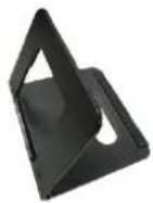
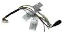
| Reader & Controller | Wall Mount | Base Bracket | Power Adapter |
 |  |  |  |
| Wire Cable | Screw Pack | Mounting Screws | QIG & Warranty Card |
 |  |  |  |
Physical Description

| Item | |
| 1 | Cameras |
| 2 | IR Lights |
| 3 | Touch Screen |
| 4 | Card Sensor |
| 5 | Lock Screw Hole |
| 6 | Ethernet Port |
| Item | |
| 7 | Speaker |
| 8 | USB Port |
| 9 | Tamper Key |
| 10 | Cable Connector |
| 11 | Debugging Port (for service only) |
Wiring
The device comes with a wire cable which connects to power input, serial device, Wiegand device and door lock, among others. The wires are color-coded and labeled for easy wiring. After wiring to external devices, connect the wafer terminal connector to the device.
You can connect a card reader using RS-485 connection. Connect the NC/NO and COM terminals to the door lock, connect the SEN and GND terminals to the door contact, and the BTN/GND terminal with the exit button, then connect the Wiegand terminal to the access controller.
When you connect an access controller through Wiegand, the face recognition device can send authentication data to the access controller. The access controller will then decide whether to unlock the door based on this information.
NOTE: The device comes with a power adapter to supply power to the device. Individual power supply is needed for external devices like card readers, exit button, door lock, etc.
Wiring Terminal Description
| Group | No. | Color | Label | Description |
| Power Input | A1 | Red | +12 V | 12 VDC Power Supply |
| A2 | Black | GND | Ground | |
| RS-485 | B1 | Yellow | 485+ | RS-485 Wiring |
| B2 | Blue | 485- | RS-485 Wiring | |
| B3 | Black | GND | Ground | |
| Wiegand | C1 | Green | W0 | Wiegand Wiring 0 |
| C2 | White | W1 | Wiegand Wiring 1 | |
| C3 | Black | GND | Ground | |
| Door Lock | D1 | White/Purple | NC | Lock Wiring (NC) |
| D2 | White/Yellow | COM | Common | |
| D3 | White/Red | NO | Lock Wiring (NO) | |
| D4 | Yellow/Green | SEN (Sensor) | Door Contact | |
| D5 | Black | GND | Ground | |
| D6 | Yellow/Gray | BTN (Button) | Exit Door Wiring |
Installation
Installation Environment
- Recommended wall installation height of device = 1.43 m to 1.9 m
- Indoor installation only.
- Avoid backlight, direct and indirect sunlight.

Backlight

Direct Sunlight

Direct Sunlight through Window

Indirect Light through Wind
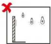
Close to Light
- For better recognition, there should be a light source in or near the installation environment.
- There should be no strong reflective objects (such as glass doors/walls, stainless steel objects, ceramic tiles, etc.) within 1 meter of the field of view of the device.
- Avoid device reflection.
- Keep the camera clean.
• Make sure the wall can bear three (3) times the weight of the device. - For accurate face recognition, the recognition distance should be greater than 30 cm.
Wall Mounting
- Mount a one-gang gang box inside the wall.
NOTE: Gang box is not supplied; purchase separately.

- Mount the wall mounting plate on the gang box using the supplied screws.
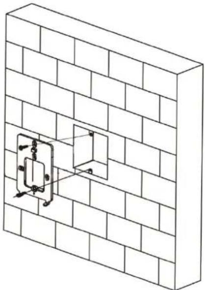
- Route the cable through the cable hole, wire the cables and insert the cables in the gang box.
- Connect the cables to the device.
- Align the device with the mounting plate to hang it, then push it down to lock the device in place.

- Then attach the bundled lock screw on the bottom hole to secure the device.
Base Mounting
The device also comes with a base bracket to easily place the device on top of flat surface like a desk or a pedestal.
- Align the base bracket on the back of the device.
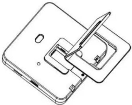
- Press the bracket with both hands on the bracket, then push up to lock the bracket to the device.

- Route the cables through the bracket hole and connect them as nedeed.
Initial Setup
Before using the device, activate the device first. The easiest way to do this is to activate through the device itself.
Activate via Device
After powering on the device, the system will go to Activate Device page.
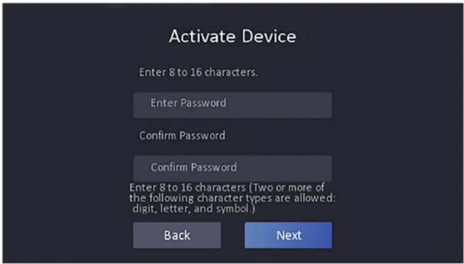
- On the prompt, create the password. The password should be 8 to 16 characters with digits, upper and lower case letters and symbols.
- Type again to confirm it, then tap Activate or Next to activate the device.
- After activation, the device will prompt for basic settings, follow the on-screen prompt to proceed.
- Select the language, then tap Next.
- Type the email address to use with the device, then tap Next.
- Set the network parameters. By default, DHCP is enabled. To continue using DHCP, tap Next. Otherwise, disable DHCP, and then fill in the network parameters manually. See Communication Settings on page 26 for more information.
- When prompted for access to a third-party platform, retain it as disabled and tap Next to continue.
-
Select the privacy settings according to your actual needs, then click Next.
-
Upload Pic. When Auth.: This function uploads the pictures captured when authentication to the platform automatically.
- Save Pic. When Auth.: This function saves the pictures when authenticating to the device.
-
Save Registered Pic.: The registered face picture will be saved to the system.
-
You will be prompted to add an administrator. Enter the Employee ID and Name. Then tap Next.
- The Add an administrator first page appears.

Tap either of the following icons to configure the administrator's face or card for access:
Face icon: Tap to capture the administrator's face. Face forward towards the camera. On the screen, place the face in the face recognition area. Tap
to capture the face and tap the check icon to confirm.
- Card icon: Tap to configure the card access of the administrator. Type the card number of swipe a card to configure it. Then, tap OK.
- You can configure the face recognition or card access or both. Once either face or card has been configured, the system will go back to Add an Administrator first page.
Repeat step 9 to add another access type or when all access has been configured, tap OK to complete setup.
Main Screen
The Main Screen shows the date and time and status icons on the upper part of the screen. On the right panel are shortcut icons. These functions need integration and are not readily available. If needed, contact your system integrator for details.

Login
Administrators can login to the device for device configuration and manage users for access control.
- Long tap the screen for 3 seconds and slide your finger left / right.
- Authenticate the administrator's face or swipe the card to enter the Main Menu page.

- Once logged in, the Main Menu page appears.
Menu Settings
Menu Page
After login, the Menu page appears. Below is the summary of the Menu.
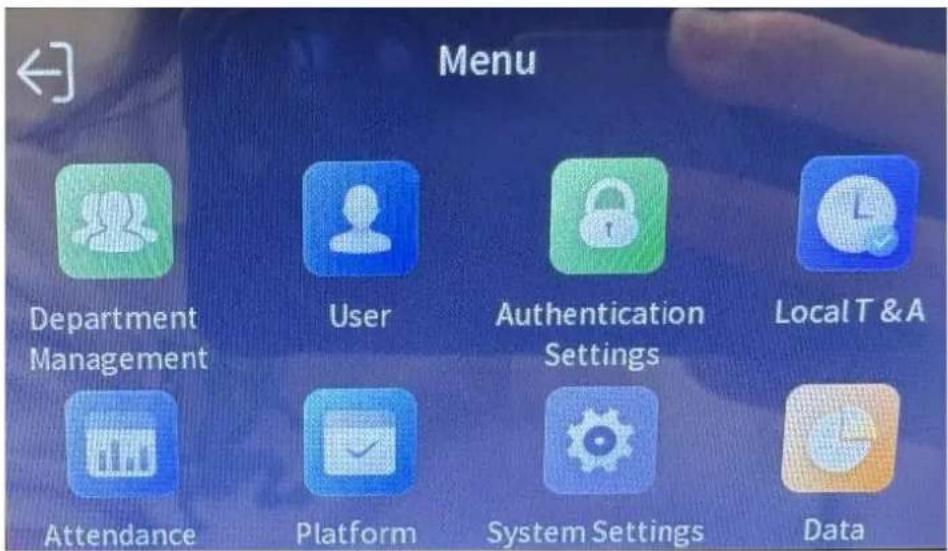
NOTE: This photo is for reference only, icons and the menu position may slightly vary. Follow the actual menu on the device.
Menu Tree
| Menu | Description |
| Department Management | The Department Management menu allows you to add, edit, delete company departments to manage people. |
| User | The User Management menu allows you to add, edit, delete, and search users, as well as set the authentication mode, permission level, and modify credentials. |
| Authentication Settings | The Authentication Settings menu allows you to configure the authentication mode and card encryption to use, door access, etc. |
| Local T & A | The T & A (Time & Attendance) Status menu allows you to set the attendance mode according to your actual situation. |
| Attendance Report | Shows the attendance reports like total attendance, attendance record, summary, abnormal attendance, etc. A USB flash drive with the data must be connected to the device to display these reports on the device. |
| Platform Attendance | The Platform Attendance allows you enable or disable attendance management through the device. Set attendance to manual or auto. |
| System Settings | The System Settings menu allows you to configure communications, basic, biometrics, preferences, and password settings. |
| Data | The Data Management menu allows you to import, export and delete user data. |
| Maintenance | The System Maintenance menu allows you to view the system information, device capacity, upgrade and restore the device to factory settings.NOTE: It is not recommended to restore to default factory settings. Instead, contact your sales agents or the customer help desk for assistance. |
Department Management
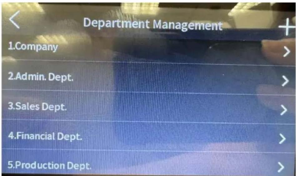
This menu has preset departments where employees can be assigned to. Tap a submenu to
access its contents and modify as needed. To create a new department, tap

User
The User menu is used for user management; to add, edit, delete and search for users or employees.
Manage User
Add User
- On the main menu page, tap User, then tap


- Tap the menu items to edit.
- Employee ID: The employee ID should be less than 32 characters. It can be a combination of lower case and upper case letters, and numbers. This should be unique per employee; should not be duplicated.
- Name: Up to 32 characters are allowed for the Name. Numbers, upper case and lower case letters, and special characters are also allowed.
• Department: Select the department where the employee belongs to.
• Face: Tap to capture the face picture. See Add Face Picture on page 21.
• Card: Tap to register a card under this user. See Add Card on page 21.
- Authentication Settings: Select "Device Mode" to set the device as access control. Or, "Custom" to combine different authentication modes together according to your actual need.
- Person Type: Select "Administrator" to set the employee as administrator or "Basic Person" as a general user.
- Tap to complete add user.

Edit User
- On the main menu page, tap User.
- Tap a username on the screen to enter the Personal Details page.
-
Tap an item to edit its content.
-
Tap to complete.

Delete User
- On the main menu page, tap User.
-
Tap a username on the screen to enter the Personal Details page.
-
Tap to delete the user.
-
Tap OK to confirm.
Search User
-
On the main menu page, tap User.
-
Type the name of the user on the search bar, then click

Add Face Picture
Add a user's face picture directly by capturing the face through the device. The face will then be used for authentication.
- On the main menu page, tap User, then tap to enter Add Person page, or tap an existing employee record.
- Fill in or edit the employee ID and credentials as needed. See Add User on page 19 for details.
- Tap Face, then position your face towards the circular recognition area.
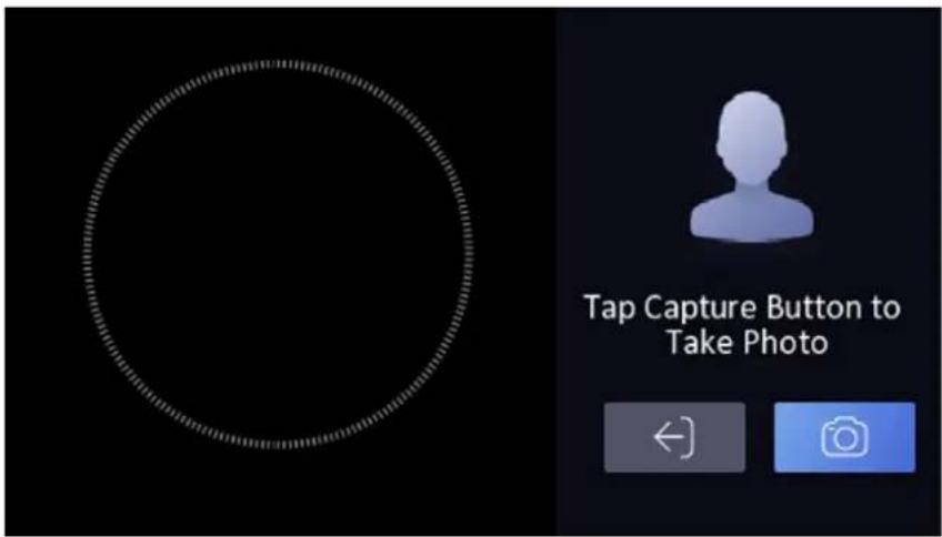
NOTE: Make sure the captured face is in good quality and is accurate. For details about the taking the face picture, see Tips in Picture Taking on page 30.
-
Click to capture the photo.
-
Tap Save to save the face picture. Or, tap Try Again to redo the picture.
Add Card
Add a card for the user to use it for authentication.
- On the main menu page, tap User, then tap + to enter Add Person page or tap an existing employee record.
-
Fill in or edit the employee ID and credentials as needed. See Add User on page 19 for details.
-
Tap Card, and then tap

- Configure the card number: you can enter the card number manually or hover the card towards the device to get the card number.
NOTE: The card number cannot be empty and it cannot be duplicated.
-
Configure the card type.
-
Tap to save the settings.
Authentication Settings
After adding a user's face picture or card credentials, go to Authentication Settings to set the authentication mode and access control parameters.
- On the main menu page, tap

to access the Authentication Settings page.

-
Tap an item then configure its contents.
-
Terminal Authentication Mode: Select "Single Credential" if only one is required for authentication like either Face or Card. Select "Multiple Credential" if both face and card are required for authentication.
- Reader Authentication Mode: Select the card reader authentication mode.
- Enable NFC Card: Enable to use NFC card for authentication.
- Enable M1 Card: Enable to use M1 card for authentication.
- Door Contact: Select "Open (Remain Open)" or "Close (Remain Closed)" according to your actual needs. By default, it si Close (Remain Closed)".
- Open Duration: Set the door unlocking duration. If the door is not opened for the set time, the door will be locked. Available door locked time range: 1 to 255 seconds.
-
Authentication Interval: Set the device authentication interval. Available interval range: 0 to 65535 seconds.
-
Tap a menu item and then edit the items.
Local T & A
You can configure and manage shift schedules, attendance rule, and holiday management on this menu. Preset schedules are available, modify and create new as needed according to your actual situation.

- On the main menu page, tap to access the Local Time & Attendance page.
- Enable Local T & A, then tap T & A.
- Tap the items to modify and create new:

- Shift management: Create or modify work shift schedules.
- Attendance Rule: Set buffer time in minutes for late check in or early check out.
• Holiday Management: Create a holiday schedule. - Add Shift Schedule: If the present schedules are not enough, you may add a new shift schedule according to your situation.
Attendance Report
Allows you to view the attendance report on the device. Requires an external USB flash drive.
On the main menu page, tap

ccess the Attendance Report page.
Platform Attendance
The Platform Attendance menu allows you to set the attendance mode as check in, check out, break in, break out, overtime in and overtime out according to your actual situation.
NOTE: Local Time & Attendance will be disabled when using Platform Attendance.
- On the main menu page, tap

to access the Platform Attendance page.

- Tap Attendance Mode and select:
• Manual: To manually set the attendance status.
- Auto: The system will automatically change the attendance status according to the configured schedule.
- Manual and Auto: The system will automatically change the attendance status according to the configured schedule and at the same time, you can manually change the status after the authentication.
- Enable and disable the Check in/out, Break in/out, Overtime in/out, as needed.
System Settings
The System Settings menu allows you to configure system settings.

- On the main menu page, tap to access the System Settings page.
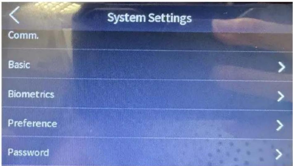
- Tap a submenu item to modify its settings.
| Submenu | Description |
| Communication | Allows you to configure the network, RS-485, Wiegand, etc. See Communication Settings on page 26. |
| Basic | Allows you to configure sound, time, sleep, langauge, privacy, video standard, etc. |
| Biometrics | You can customize face parameters to improve the face recognition performance. See Biometric Parameters on page 27. |
| Preference | Allows you to select the screen theme and enable or disable shortcut keys. |
| Password | Allows you to modify the device password set during initial setup. |
Communication Settings
You can set the wired network, the Wi-Fi parameter, the RS-485 parameters, the Wiegand parameters, and ISUP on the communication settings page.
Set Wired Network
- On System Settings page, tap Comm. > Wired Network.
- Enable DHCP for the system to automatically assign IP address, subnet mask, and gateway. Disabled DHCP to manually set the IP address, subnet mask, and gateway. NOTE: The device must be in the same network segment with the computer.
- Set the DNS parameters. You can enable Auto Obtain DNS, set the preferred DNS server and the alternate DNS server.
Set RS-485 Parameters
The device can connect to external access controller, secure door control unit or card reader via RS-485 connection.
- On System Settings page, tap Comm. > RS-485.
- Enable RS-485.
- Tap Peripherals, then according to your actual needs, select the type of external device to connect: Access Controller, Control Unit, or Card Reader.
NOTE: If Access Controller is selected:
• If the device is connected to a terminal, set the RS-485 address as 2
- If the device is connected to a controller, set the RS-485 address according to the door number.
Set Wiegand Parameters
- On System Settings page, tap Comm. > Wiegand.
- Enable Wiegand.
- Select a transmission direction: "Output", the device can connect to an external access controller.
- Select how the two devices will transmit the card no.: via Wiegand 26 or Wiegand 34.
Biometric Parameters
You can customize the face parameters to improve face recognition performance.
- On System Settings page, tap Biometrics.
- Tap a submenu item to modify its settings.
| Submenu | Description |
| Face Liveliness Level | Set the matching security level when performing live face authentication. |
| Recognition Distance | Set the valid distance between the user and the camera when authenticating. |
| Face Recognition Interval (sec) | The interval time between two continuous face recognitions when authenticating. Allowable range from 1 to 10 seconds. |
| Face 1:N Security Level | Set the matching threshold when authenticating via 1:N matching mode. The larger the value, the smaller the false accept rate and the larger the false rejection rate. |
| Face 1:1 Security Level | Set the matching threshold when authenticating via 1:1 matching mode. The larger the value, the smaller the false accept rate and the larger the false rejection rate |
| Eco Mode Settings | After enabling the ECO mode, the device will use the IR camera to authenticate faces in the low light or dark environment. And you can set the ECO mode threshold, ECO mode (1:N), ECO mode (1:1), Face with mask & face (1:1 ECO) and Face with mask & face (1:N ECO).ECO Threshold: When enabling the ECO mode, you can set the ECO mode's threshold. The larger the value, the easier the device entering the ECO mode.ECO Mode (1:1): Set the matching threshold when authenticating via ECO mode 1:1 matching mode. The larger the value, the smaller the false accept rate and the larger the false rejection rate.ECO Mode (1:N): Set the matching threshold when authenticating via ECO mode 1:N matching mode. The larger the value, the smaller the false accept rate and the larger the false rejection rateFace with Mask & Face (1:1 ECO): Set the matching value when authenticating with face mask via ECO mode 1:1 matching mode. The larger the value, the smaller the false accept rate andthe larger the false rejection rate.Face with Mask & Face (1:N ECO): Set the matching value when authenticating with face mask via ECO mode 1:N matching mode. The larger the value, the smaller the false accept rate and the larger the false rejection rate. |
| Mask Settings | When enabled, the system will recognize the captured face with mask picture. You can set face with mask & face 1:N level and the strategy.Strategy: Set the None, Reminder of Wearing and Must Wear strategy.Reminder of Wearing: If the person does not wear a face mask when authenticating, the device displays a notification, and the door will open.Must Wear: If the person does not wear a face mask when authenticating, the device displays a notification, and the door remains closed.None: If the person does not wear a face mask when authenticating, the device will not prompt a notification.Face with Mask & Face (1:1): Set the matching value when authenticating with face mask via 1:1 matching mode. The larger the value, the smaller the false accept rate and the larger the false rejection rate.Face with Mask & Face (1:N): Set the matching value when authenticating with face mask via 1:N matching mode. The larger the value, the smaller the false accept rate and the larger the false rejection rate. |
Data
The Data menu allows you to import, export and delete user data on the device. For importing and exporting data, an external USB flash drive is required.
On the main menu page, tap to access the Data page.
Maintenance
The Maintenance menu allows you to view the system information, device capacity, reset or restore factory default settings and reboot device.
On the main menu page, tap

to access the Maintenance page.
Tips in Picture Taking
Take note of the correct expression, posture, and size of face when taking the face photo to ensure recognition accuracy.
| Expression |  | ·Keep expression natural.·Do not wear hat, sunglasses and other accessories.·Do not allow hair to cover your eyes, ears, etc.·Do not use heavy makeup. | |||
| Posture | Face should be facing the camera. | ||||
 |  |  |  |  | |
| Size |  |  |  | ||
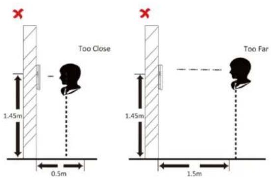
Positions When Taking or Authenticating Face


ACTi
Connecting Vision
Copyright © 2021, ACTi Corporation All Rights Reserved
7F, No. 1, Alley 20, Lane 407, Sec. 2, Ti-Ding Blvd., Neihu District, Taipei, Taiwan 114, R.O.C.
TEL: +886-2-2656-2588 FAX: +886-2-2656-2599
Email: sales@acti.com


- FACE RECOGNITION READER & CONTROLLER
- USER'S MANUAL
- REGULATORY INFORMATION
- FCC INFORMATION
- EU CONFORMITY STATEMENT
- ⚠️DANGER
- ⚠️ CAUTIONS
- CONTENTS
- INTRODUCTION......8
- INSTALLATION....11
- INITIAL SETUP 14
- MENU SETTINGS....17
- TIPS IN PICTURE TAKING....30
- INTRODUCTION
- WIRING
- INSTALLATION
- INSTALLATION ENVIRONMENT
- WALL MOUNTING
- BASE MOUNTING
- INITIAL SETUP
- ACTIVATE VIA DEVICE
- MAIN SCREEN
- LOGIN
- MENU SETTINGS
- MENU PAGE
- DEPARTMENT MANAGEMENT
- USER
- MANAGE USER
- ADD USER
- EDIT USER
- DELETE USER
- SEARCH USER
- ADD FACE PICTURE
- ADD CARD
- AUTHENTICATION SETTINGS
- LOCAL T & A
- ATTENDANCE REPORT
- PLATFORM ATTENDANCE
- SYSTEM SETTINGS
- COMMUNICATION SETTINGS
- SET WIRED NETWORK
- SET RS-485 PARAMETERS
- SET WIEGAND PARAMETERS
- BIOMETRIC PARAMETERS
- DATA
- MAINTENANCE
- TIPS IN PICTURE TAKING
- POSITIONS WHEN TAKING OR AUTHENTICATING FACE
- ACTI
- CONNECTING VISION
Brand : ACTi
Model : R71CF-312
Category : Security System