
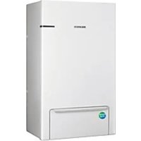
MHC-300FP - Heat pump SAMSUNG - Free user manual and instructions
Find the device manual for free MHC-300FP SAMSUNG in PDF.


| Product Type | Mini Hi-Fi System |
| Brand | Samsung |
| Model | MHC-300FP |
| Dimensions (W x H x D) | 250 x 200 x 300 mm |
| Weight | 5.0 kg |
| Power Output | 120 W RMS |
| Power Supply | AC 220-240V, 50/60 Hz |
| Playback Formats | CD, CD-R/RW, MP3, WMA |
| Radio Tuner | FM/AM, 30 presets |
| Connectivity | USB, Bluetooth, AUX In, Headphone Out |
| Speaker Configuration | 2-way, 2 speakers |
| Display | LCD with backlight |
| Remote Control | Included, battery type AAA |
| Special Features | Dynamic Bass Boost, Karaoke Function |
| Maintenance | Clean with soft dry cloth; avoid liquids |
| Safety | Class II insulation, auto power-off after 2 hours idle |
| Spare Parts & Repairability | Remote, speakers, power cord; service by qualified technician |
| Included Accessories | User manual, remote control, FM antenna, AUX cable |
| Energy Consumption | Standby: 0.5 W; Operating: 35 W |
| Warranty | 1 year |
Frequently Asked Questions - MHC-300FP SAMSUNG
User questions about MHC-300FP SAMSUNG
0 question about this device. Answer the ones you know or ask your own.
Ask a new question about this device
Download the instructions for your Heat pump in PDF format for free! Find your manual MHC-300FP - SAMSUNG and take your electronic device back in hand. On this page are published all the documents necessary for the use of your device. MHC-300FP by SAMSUNG.
USER MANUAL MHC-300FP SAMSUNG
Air to Water Heat Pump
Installation manual
Backup Heater MHC-300FP
• Thank you for purchasing this Samsung Product. - Before operating this accessory kit, please read this manual carefully and retain it for future reference.
Contents
PREPARATION
Safety precautions 3
Product specifications 6
Typical application examples 9
Main components 11
INSTALLATION
Installing the accessory kit 12
Pipe work 14
Wiring work 15

Correct Disposal of This Product
(Waste Electrical & Electronic Equipment)
(Applicable in countries with separate collection systems)
This marking on the product, accessories or literature indicates that the product and its electronic accessories (e.g. charger, headset, USB cable) should not be disposed of with other household waste at the end of their working life. To prevent possible harm to the environment or human health from uncontrolled waste disposal, please separate these items from other types of waste and recycle them responsibly to promote the sustainable reuse of material resources.
Household users should contact either the retailer where they purchased this product, or their local government office, for details of where and how they can take these items for environmentally safe recycling.
Business users should contact their supplier and check the terms and conditions of the purchase contract. This product and its electronic accessories should not be mixed with other commercial wastes for disposal.
For information on Samsung's environmental commitments and product regulatory obligations, e.g. REACH, visit our sustainability page available via www.samsung.com
Safety precautions
All materials supplied to this manual are indispensable for the safety of equipment.
Users shall establish appropriate safety and health practices and determine the applicability of regulatory limitation based on following descriptions prior to use.

WARNING
- Always disconnect the air to water heat pump from the power supply before servicing it or accessing its internal components.
- Verify that installation and testing operations are performed by qualified personnel.
- Verify that the air to water heat pump is not installed in an easily accessible area.
GENERAL INFORMATION
▶ Carefully read the content of this manual before installing the air-to-water heat pump and store the manual in a safe place in order to be able to use it as reference after installation. For maximum safety, installers shall always carefully read the following warnings. - Store the user and installation manual in a safe location and remember to hand it over to the new owner if the air-to-water heat pump is sold or transferred. This manual explains how to install the backup heater kit (MHC-300FP) in combination with SAMSUNG mono-type heat pump units. The use of other types of units with different control systems may damage the product and invalidate the warranty. The manufacturer shall not be responsible for damages arising from the use of non-compliant combinations. The manufacturer shall not be responsible for damage originating from unauthorized changes or the improper connection of electric and hydraulic lines. Failure to comply with these instructions or to comply with the requirements set forth in the “Operating limits” table, included in the manual, shall immediately invalidate the warranty. ▶ Do not use the units if damaged. If problems occur, switch the unit off and disconnect it from the power supply. In order to prevent electric shocks, fires, or injuries, always stop the unit, disable the protection switch, and contact SAMSUNG's technical support if the unit produces smoke, if the power cable is hot or damaged, or if the unit is very noisy. ▶ Always remember to inspect the unit, electric connections, refrigerant tubes, and protections regularly. These operations should be performed by qualified personnel only. The unit contains moving parts, which should always be kept out of the reach of children. ▶ Do not attempt to repair, move, alter, or reinstall the unit. If performed by unauthorized personnel, these operations may cause electric shocks or fires. ▶ Do not place containers with liquids or other objects on the unit. ▶ All the materials used for the manufacturing and packaging of the air-to-water heat pump are recyclable. The packing material and exhausted batteries of the remote control (optional) must be disposed of in accordance with current laws. ▶ Do not disassemble and alter the heater at your own discretion. ▶ Wear protective equipment (such as safety gloves, goggles, and headgear) during installation and maintenance works. Installation/repair technicians may be injured if protective equipment is not properly equipped. ▶ Do not use means to accelerate the defrost operation or to clean, other than those recommended by Samsung. ▶ Do not pierce or burn.
Safety precautions
INSTALLING THE BACKUP HEATER KIT
Upon receipt, inspect the product to verify that it has not been damaged during transport. If the product appears damaged, DO NOT INSTALL it and immediately report the damage to the carrier or retailer (if the installer or the authorized technician has collected the material from the retailer). After completing the installation, always carry out a functional test (commissioning) and provide the instructions on how to operate the air to water heat pump to the user. Do not use the air to water heat pump in environments with hazardous substances or close to equipment that release free flames to avoid the occurrence of fires, explosions or injuries.
For disposal of the product, follow the local laws and regulations. Do not work in a confined place. The work area shall be blocked.
The pipings shall be installed in the position where there are no substances that may result in corrosion.
The following checks shall be performed for installation:
- The ventilation devices and outlets are operating normally and are not obstructed.
- Markings and signs on the equipment shall be visible and legible.
Make sure that the work area is safe from flammable substances. The units are not explosion proof so they must be installed with no risk of explosion. Do not install where there is a risk of combustible gas leakage. Do not place heat sources. Be cautious not to generate a spark as follows:
- Do not remove the fuses with power on.
- Do not disconnect the power plug from the wall outlet with power on.
- It is recommended to locate the outlet in a high position. Place the cords so that they are not tangled.
Do not install the backup heater kit in the following areas:
- Area filled with minerals, splashed oil, or steam. It will deteriorate plastic parts, causing failure or leakage.
- Area that is close to heat sources.
- Area that produces substances such as sulfuric gas, chlorine gas, acid, and alkali. It may cause corrosion of the pipings and brazed joints.
- Area that can cause leakage of combustible gas and suspension of carbon fibers, flammable dust, or volatile flammables.
- Area where refrigerant leaks and settles.
- Area where animals may urinate on the product. Ammonia may be generated.
POWER SUPPLY LINE, FUSE OR CIRCUIT BREAKER
▶ Always make sure that the power supply is compliant with current safety standards. Always install the air to water heat pump and the accessories like the backup heater kit in compliance with current local safety standards. ▶ Always verify that a suitable grounding connection is available. ▶ Verify that the voltage and frequency of the power supply comply with the specifications and that the installed power is sufficient to ensure the operation of any other domestic appliance connected to the same electric lines. ▶ Always verify that the cut-off and protection switches are suitably dimensioned. ▶ Verify that the air to water heat pump is connected to the power supply in accordance with the instructions provided in the wiring diagram included in the manual. ▶ Always verify that electric connections (cable entry, section of leads, protections...) are compliant with the electric specifications and with the instructions provided in the wiring scheme. Always verify that all connections comply with the standards applicable to the installation of air to water heat pumps.

CAUTION
Make sure that you earth the cables.
- Do not connect the earth wire to the gas pipe, water pipe, lighting rod or telephone wire. If earthing is not complete, electric shock or fire may occur.
• Install the circuit breaker.
- If the circuit breaker is not installed, electric shock or fire may occur.
- Install the power cable and communication cable of the indoor and outdoor unit at least 1m away from the electric appliance.
Product specifications
Product compatibility
| Type Platform Image Model name MHC-300FP | |||||
| Mono | Indoor Unit | ClimateHub AE200DNW*PK  | ● | ||
Hydro Units AE160DNY*PK  | ● | ||||
| Control Kit |  | MIM-E03FN | ● | ||
 | MIM-E03CNMIM-E03EN | ● | |||
| Outdoor Unit | UBS-M |  | AE050CXYBEK | ● | |
| AE080CXYB*K | ● | ||||
| UBS |  | AE120CXYB*K | ● | ||
| AE160CXYB*K | ● | ||||
Accessories
 |  |  |
| Installation Manual (1) Wall mounting template (1) Terminal Block Kit (1) | ||
 |  |  |
| Screw (1) | Temp. Sensor (1)(White wire)(ClimateHub/Hydro Unit) | Temp. Sensor (1)(Red wire)(R290 Pump Integrated Outdoor Unit/Control Kit) |
Product specifications
Specifications
| Electrical Specification Unit MHC-300FP | |||
| Backup Heater | Number of Heating Coil EA 3 | ||
| Capacity Combination | kW 1.0 + 1.0 + 1.0 | ||
| Heating Steps | Step 1 | ||
| Power Supply V, ∅, Hz | 220 ~ 240, 1, 50 | ||
| 380 ~ 415, 3, 50 | |||
| Thermostat (Thermal Fuse) °C 98 | + 0.5 | ||
| Net Dimensions mm (W x H x D) | 330 x 460 x 200 | ||
| Packing Dimensions mm (W x H x D) | 399 x 559 x 295 | ||
| Net Weight (unit) kg 11.8 | |||
| Water connections | Leaving Water Pipe inch Male PT 1" | ||
| Entering Water Pipe | inch Male PT 1' | ||
Typical application examples

WARNING
- The application examples given below are for illustration purposes only.
- When the SAMSUNG Air-to-Water Heat Pump system is used in series with another heat source (e.g., gas boiler), ensure that the return water temperature does not exceed the maximum water temperature of the outdoor unit (Max water temperature is determined according to the type of outdoor unit model: 65°C/70°C/75°C).
- The unit is only to be used in a closed water system. Application in an open water circuit can lead to excessive corrosion of the water piping.
- SAMSUNG cannot be responsible for incorrect or unsafe situations in the water system. Make sure that the boiler, radiators, convectors, solar collectors, UFHs, FCUs, additional pumps, pipings, and controls in the water system are in accordance with relevant local laws and regulations under the installer's responsibility.
- SAMSUNG shall not be held liable for any damage resulting from not observing this rule.
- SAMSUNG does not provide specific water system components such as pressure relief valve, air vent valve, buffer tank, etc. Installers and end-users shall consider how to install the above designated components in the overall water system depending on the installation conditions. If the components are not installed in appropriate locations, the water system cannot be operated as designed.
* The below examples are for illustration purposes only.
Application 1: Space heating + water heating
* AE200DNWMPK (Standard)
![graph TD A["Outdoor unit"] --> B["ClimateHub"] B --> C["Hot Water"] B --> D["Cold Water"] B --> E["Backup Heater"] E --> F["Balancing Vessel"] F --> G["Al Home"] G --> H["45°C Supply Header"] H --> I["Return Header"] I --> J["Radiators or Convectors"] J --> K["Supply Header"] K --> L["Return Header"…](/content/2026/07/1448884/images/de91d0ddd8750cca7abefd408c19e07d9d389040e6f6ad65564872493baeb8c5.jpg)
Typical application examples
Application 2: Space heating + water heating
* AE160DNYMPK (Standard)
![graph TD A["Outdoor Supply Range"] --> B["Hydro Unit"] B --> C["3rd Party DHW Tank"] C --> D["Backup Heater"] D --> E["Balancing Vessel"] E --> F["Al Home"] E --> G["Supply Header"] E --> H["Return Header"] E --> I["Radiators or Convectors"] E --> J["Under-Floor Heating Coils"] E --> K["Supply Heade…](/content/2026/07/1448884/images/f2f67bea2b9394003ccb68893bc55d541d8cc9ef2433ed0ab7b623757c85e16f.jpg)
Application 3: Space heating + water heating
AE***CXYB*K (Outdoor unit)

| No. Name Note | ||
| 1 | Air Vent Air purging when charging water | |
| 2 | Backup Heater 3kW | |
| 3 | Control Box Magnetic switches, Terminal blocks | |
| 4 | Entering Water Pipe Male PT 1" | |
| 5 | Leaving Water Pipe Male PT 1" | |
Installing the accessory kit
Installation of the backup heater
The backup heater should be installed indoors and meet the following conditions.
▶ Installation site should be sheltered from frost. ▶ In area with suitable space for servicing. ▶ A place with adequate ventilation. ▶ Where there is no risk of leakage of flammable gases. There is a provision for condensate drain and pressure relief valve blow-off.
The wall for installation is a flat, vertical and non-combustible wall, capable of supporting the operation weight of the unit.
Installation space
▶ Ensure to leave the appropriate space as indicated in the drawing.
▶ Installation site should be secured with adequate ventilation so that the components of hydro unit will not be damaged from overheating.
(Unit: mm)

Before installing the indoor unit, fix the wall mounting template on the wall. This sheet has a function to take correct position for the wall mounting bracket and screws.

Wall mounting template
Mounting the backup heater
- Uncover the backup heater accessory.
- Open the cabinet and control box covers.
- Attach "Wall mounting template" to the wall and mark the locations of bolts, and drill 4 holes for screws at the location.
- Detach "Wall mounting template" and insert plugs and screws properly.
- Hang the backup heater onto the wall. Make sure it is fixed properly.
- Fasten the backup heater on the wall with screws.

→
→

Pipe work
Water pipe work
All entering, leaving water direction is embossed right above the pipe.
Please connect the pipe with attention to the direction of the arrow.
Whole water plumbing system including Backup heater kit shall be installed by a qualified technician and must comply with all relevant European and national regulations.
▶ Allowable water pressure of Backup heater kit is maximum 3.0bar.
An air-vent valve is integrated on the Backup heater kit. Please purge air after filling with system water and close the air vent valve after removing air from the pipework. Do not over tighten.
▶ All air vents in the water circuit must be closed after the air has been purged. The automatic air vents should be closed with a cover. In case any leaking refrigerant enters the water circuit, the gas should not be automatically discharged into the occupied space.

Air vent valve
Air-vent valve is provided in the Hydro unit.
However, provide air vents at all the highest points of the system, so that automatic release of air in the water circuit is possible.

Wiring work

CAUTION
- Field-supplied electrical components such as power switch, circuit breakers, wires, terminal blocks, etc. must be properly chosen in compliance with national legislation or regulation.
- Switch off the power supply before making any connections.
- All field wiring and components must be installed by a licensed electrician.
- Use a dedicated power supply.
- All power connections must be protected from dew condensation by thermal insulation.
- The system shall be earthed. Do not earth the unit to a utility pipe, surge absorber or telephone earth. Incomplete earthing may cause electrical problems.
How to Connect the Backup Heater to ClimateHub/Hydro Unit
- Take the Backup Heater Terminal Block KIT.
- Install the Terminal Block KIT after identifying the correct screw hole.

- Connect the wire B19 (Neutral) and CNP002. * It's just for providing an ON/OFF Control Signal of the BACKUP HEATER. * The N Phase of the HEATER Signal can be connected to B5, B7, B11, B15 instead of B19 (Maximum 2 wires can be connected under 1 screw).

Wiring work
- Connect the cable between the Terminal Block KIT and the Backup Heater.

| Model | Description | No. of Wires | Max. A | Thickness | Supply Scope |
| MHC-300FP Indoor 2 0.3 A | 0.75mm2 H05RN-F or H07RN-F | Field Wiring (AC230Vac) |
How to Connect the Backup Heater to R290 Pump Integrated Outdoor Unit/Control Kit
- Take the Backup Heater Terminal Block KIT.
- Install the Terminal Block KIT after identifying the screw hole.

Wiring work
- Connect the wire to B19 (Neutral) and CNP1 through the marked hole. * This is only for providing an ON/OFF control signal for the backup heater. * The N phase of the heater signal can be connected to B5, B7, B11, or B15 instead of B19 (maximum 2 wires can be connected under one screw).


- Connect the cable between the Terminal Block KIT and the Backup Heater.

| Model | Description | No. of Wires | Max. A | Thickness | Supply Scope |
| MHC-300FP Indoor 2 0.3 A | 0.75mm2 H05RN-F or H07RN-F | Field Wiring (AC230Vac) |
How to Connect the Temp. Sensor to PCB
- Take the Temperature sensor.
- Insert the connector of the temperature sensor into the PBA.
- As shown below, align the wires of the temperature sensor through the inside of the C-BOX, and then fix the sensor to the pipe using a clip.
* Temp. Sensor with white wire is used for Climated Hub / Hydro Unit.
* Temp. Sensor with red wire is used for Outdoor Unit / Control Kit.

Wiring work
Connection of the power supply
| Model Description | No. of Wires | Max. A | Thickness Supply | Scope |  | ||
| MHC-300FP | Heater Power | 3phase Heater | 4 + ground | 4.6 A | 1.5mm2 ↑ H05RN-F or H07RN-F | Field Supply (380-415Vac, Input) | |
| 1phase Heater | 2 + ground | 13.7 A | 2.5mm2 ↑ H05RN-F or H07RN-F | Field Supply (220-240Vac, Input) | |||

CAUTION
- Heater power must be configured through each RCBO or MCCB + RCCB.
- Temp. Sensor with Red wire is used for Outdoor Unit / Control Kit.
- Backup heater should use the right power according to the power of the outdoor unit.
- When using 1Phase

- When using 3Phase


CAUTION
- Circuit Breaker (RCBO or MCCB + RCCB) for Backup Heater shall be installed by installers because they are not sub-parts in the units.
- If the supply cable is damaged, it must be replaced by a special cable or assembly available from the manufacturer or installer.
- It cause damage to HEATER if the HEATER POWER is not connected correctly. You should make certain that R,S,T,N is connected correctly before turning on the HEATER POWER.
- When the HEATER POWER is 1Phase(220\~240Vac), you should connect L1,L2,L3 as L phase together
* RCBO : Residual Circuit Breaker with Over Load
RCCB : Residual Current Circuit Breaker
MCCB: Molded case circuit breaker
Connection of the backup heater power supply

CAUTION
- Do not use a power supply shared by other appliances. Each component for outdoor unit, indoor unit, and backup heater has a dedicated power supply.
| Model | Outdoor unit Power(Φ, #, V, Hz) | 1 Phase RCBO(A) | 3 Phase RCBO(A) |
| MHC-300FP | 1,2,220-240,50 20A N/A | ||
| 3,4,380-415,50 N/A 15A |

NOTE
- The power consumption of the backup heater is calculated according to the heater signal, so an error may occur with the actual usage.
Changing of field setting value
- When connecting the Backup Heater MHC-300FP to ClimateHub/Hydro Units, please set FSV#4026 (External Heater).
- When connecting the Backup Heater MHC-300FP to the outdoor unit/control kit, FSV#4021 \~ FSV#4025 (Backup heater) needs to be set, and #4026 is "unused" setting. * Please refer to the user manual for detailed field setting value settings. [ ClimateHub/ Hydro Unit / Outdoor Unit / Control Kit]
Memo


- AIR TO WATER HEAT PUMP
- INSTALLATION MANUAL
- CONTENTS
- PREPARATION
- INSTALLATION
- (APPLICABLE IN COUNTRIES WITH SEPARATE COLLECTION SYSTEMS)
- SAFETY PRECAUTIONS
- WARNING
- GENERAL INFORMATION
- INSTALLING THE BACKUP HEATER KIT
- POWER SUPPLY LINE, FUSE OR CIRCUIT BREAKER
- PRODUCT SPECIFICATIONS
- TYPICAL APPLICATION EXAMPLES
- APPLICATION 1: SPACE HEATING + WATER HEATING
- INSTALLING THE ACCESSORY KIT
- INSTALLATION OF THE BACKUP HEATER
- INSTALLATION SPACE
- MOUNTING THE BACKUP HEATER
- PIPE WORK
- WATER PIPE WORK
- AIR VENT VALVE
- WIRING WORK
- HOW TO CONNECT THE BACKUP HEATER TO CLIMATEHUB/HYDRO UNIT
- HOW TO CONNECT THE BACKUP HEATER TO R290 PUMP INTEGRATED OUTDOOR UNIT/CONTROL KIT
- HOW TO CONNECT THE TEMP. SENSOR TO PCB
- CONNECTION OF THE BACKUP HEATER POWER SUPPLY
- CHANGING OF FIELD SETTING VALUE
- MEMO
Brand : SAMSUNG
Model : MHC-300FP
Category : Heat pump