
AE080CXYBEK - Heat pump SAMSUNG - Free user manual and instructions
Find the device manual for free AE080CXYBEK SAMSUNG in PDF.


| Product Type | Outdoor Unit for Heat Pump System |
| Brand | Samsung |
| Model | AE080CXYBEK |
| Refrigerant Type | R32 |
| Cooling Capacity | 8.0 kW (27300 BTU/h) |
| Heating Capacity | 9.0 kW (30700 BTU/h) |
| Power Supply | 230V / 50Hz / Single Phase |
| Outdoor Unit Dimensions (WxHxD) | 880 x 640 x 310 mm |
| Outdoor Unit Weight | 65 kg |
| Pipe Connection Liquid/Gas | 1/4 inch / 3/8 inch |
| Maximum Pipe Length | 50 m |
| Energy Efficiency Class (Cooling/Heating) | A++ / A+ |
| Operating Temperature Range (Cooling) | -15°C to 46°C |
| Operating Temperature Range (Heating) | -20°C to 24°C |
| Noise Level (Outdoor Unit) | 45 dB(A) |
| Functions | Cooling, Heating, Dehumidification, Auto Mode, Timer |
| Defrost Function | Yes (Automatic) |
| Self-Diagnosis | Yes |
| Maintenance | Clean air filter every 2 weeks; check fins and coils annually |
| Safety Features | Overload protection, anti-freeze, short circuit protection |
| Repairability | Modular design, spare parts available, serviceable by certified technicians |
Frequently Asked Questions - AE080CXYBEK SAMSUNG
User questions about AE080CXYBEK SAMSUNG
0 question about this device. Answer the ones you know or ask your own.
Ask a new question about this device
Download the instructions for your Heat pump in PDF format for free! Find your manual AE080CXYBEK - SAMSUNG and take your electronic device back in hand. On this page are published all the documents necessary for the use of your device. AE080CXYBEK by SAMSUNG.
USER MANUAL AE080CXYBEK SAMSUNG
Air to Water Heat Pump
Installation manual
EHS Mono Outdoor Unit AE***CXYB**
- Thank you for purchasing this Samsung product.
- Before operating this unit, please read this manual carefully and retain it for future reference.
Safety Information 4
Handling the box 7
Unpacking the outdoor unit 7
Product line-up and accessories 7
Unit installation 8
Preparing the installation of the outdoor unit 8
Choosing the installation location 8
Safety Zone 9
Moving the outdoor unit 12
Mounting the outdoor unit 12
Outdoor unit drain work 13
Piping installation 14
About the piping work 14
Connecting the water pipes 14
Water Charging 14
Setting capacity and pre-pressure of the expansion vessel 15
Protection of the water circuit freezing 15
Outdoor water piping insulation 17
Minimum active water volume 17
Electrical installation 18
Precautions when connecting the electrical wiring 18
Electrical wiring diagram 18
Outdoor wiring 19
Power and communication cable configuration 20
To connect the power supply 20
To connect the communication cable 20
Control PBA 21
Temp. Sensor for DHW, PV / Peak power control Signal 21
To connect external sensors 22
To connect smart grid 22
System configuration 23
Setting the outdoor options via K-button tactile switches 23
Testing operations 24
FSV Upload / Download 25
Charging refrigerant 26
Important information: regulation regarding the refrigerant used 26
Troubleshooting
27
Troubleshooting of error code 27
Technical data 29
Refrigerant circuit diagram 29
Piping & Wiring diagram 31

Correct Disposal of This Product (Waste Electrical & Electronic Equipment)
(Applicable in countries with separate collection systems)
This marking on the product, accessories or literature indicates that the product and its electronic accessories (e.g. charger, headset, USB cable) should not be disposed of with other household waste at the end of their working life. To prevent possible harm to the environment or human health from uncontrolled waste disposal, please separate these items from other types of waste and recycle them responsibly to promote the sustainable reuse of material resources.
Household users should contact either the retailer where they purchased this product, or their local government office, for details of where and how they can take these items for environmentally safe recycling.
Business users should contact their supplier and check the terms and conditions of the purchase contract. This product and its electronic accessories should not be mixed with other commercial wastes for disposal.
For information on Samsung's environmental commitments and product-specific regulatory obligations, e.g. REACH, visit: https://www.samsung.com/uk/sustainability/environment/environment-data/
※ Please refer to the reference guide for details.
General
- All materials supplied in this manual are indispensable for the safety of the equipment. Users shall establish appropriate safety and health practices and determine the applicability of regulatory limitations based on the following descriptions before use.
- This unit contains a high flammable refrigerant, R-290. There are fires and explosions when refrigerant leaks. Be sure to follow the storage, installation, maintenance instructions. (Please refer to the reference guide for details.)
- Always disconnect the air to water heat pump from the power supply before servicing it or accessing its internal components.
- Verify that installation and testing operations are performed by qualified personnel.
- Verify that the air to water heat pump is not installed in an easily accessible area (vandalism/ sabotage/ other harmful activities).
- Carefully read the content of this manual before installing the air-to-water heat pump and store the manual in a safe place in order to be able to use it as a reference after the installation.
- For maximum safety, installers shall always carefully read the following warnings.
- Store the user and installation manual in a safe location and remember to hand it over to the new owner if the air-to-water heat pump is sold or transferred of ownership.
- This manual explains how to install an outdoor unit and connect it to the indoor part (wired remote control and EHS Wi-Fi kit). Use of other types of devices with the control system may damage the device and void the warranty.
- The manufacturer shall not be responsible for damages arising from noncompliant units or parts.
- The manufacturer shall not be responsible for damage originating from unauthorized changes or the improper connection of electric and hydraulic lines. Failure to comply with these instructions or to comply with the requirements outlined in the "Operating limits" table included in the manual shall immediately invalidate the warranty.
- To prevent serious system damage and user injuries, precautions and other notices shall be observed.
- Failure to comply with these instructions or to comply with the requirement on the Operating Range (Heat: -25~35 °C/ DHW: -25~43 °C/ Cool: 10~46 °C) outlined in the Product Specification shall immediately invalidate the warranty.
- Do not use the units if you see some damages on the units and recognize something problematic such as loud noise or smell of burning.
- To prevent electric shocks, fires or injuries, always stop the unit, ultimately rendering the product powerless. Contact Samsung's technical support if the unit produces smoke, if the power cable is hot or damaged or if the unit is very noisy.
- Always remember to inspect the unit, electric connections, refrigerant pipework and protections regularly. These operations shall be performed by qualified personnel only.
- The unit contains moving and electrical parts, which should always be kept out of the reach of children.
- Do not attempt to repair, move, alter or reinstall the unit by unauthorized personnel. These operations may cause product damage, electric shocks, and fires.
- Do not place containers with liquids or other objects on the unit. Never sit or stand on the product.
- All the materials used for the manufacturing and packaging of the air-to-water heat pump are recyclable.
- The packing material and exhausted batteries of the remote controller (optional) must be disposed of in accordance with local regulations.
- Always make sure that the power supply is compliant with local safety standards.
- For use in Europe: This appliance can be used by children aged 8 years and above and persons with reduced physical, sensory or mental capabilities or lack of experience and knowledge if they have been given supervision or instruction concerning the use of the appliance in a safe way and understand the hazards involved. Children shall not play with the appliance. Cleaning and user maintenance shall not be done by children without supervision.
- This appliance is not intended for use by persons (including children) with reduced physical, sensory, or mental capabilities, or lack of experience and knowledge, unless they have been given supervision or instruction concerning the appliance use by a person responsible for their safety. Children should be supervised to ensure they do not play with the appliance.
- Be sure not to perform power cable modification, extension wiring, and multiple wire connection.
- It may cause electric shock or fire due to poor connection, poor insulation, or current limit exceedance.
- Do not use means to accelerate the defrosting operation or to clean, other than those recommended by Samsung.
- Do not pierce or burn.
- Be aware that refrigerants may not contain an odour.
- Determine the installation location regarding the conditions cited in this reference guide and obtain the user's approval.
- The outdoor unit must not be placed on its side or upside down, as the compressor lubrication oil will run into the cooling circuit and seriously damage the unit.
- Combine R-290 products only or an error signal appears and the products will not operate. Check with the compatibility table provided by Samsung.
- Make sure to safely dispose of packing materials. Packing materials, such as nails and other metal or wooden pallets may cause injuries to humans and animals by unsafe disposal.
Installing the unit

NOTE
- When installing the unit, remember to firstly connect the water pipework, then the electrical lines. Always disassemble the electric lines before the water pipework.
- Upon receipt, inspect the product to verify that it has not been damaged during transport. If the product appears damaged, do not install it, as the refrigerant may leak. A leaking product should be moved to a safe outdoor place. There should be no ignition source within 6 meters. Products should be located where the refrigerant can be safely removed or professionally removed and discarded by service technicians. Immediately report the damage to the supplier of the Samsung products (distributor/retailer/local Samsung branch office).
- After completing the installation, always carry out a functional test (commissioning, including reporting) and provide instructions on how to operate the air to water heat pump to the user.
- Do not use the air to water heat pump in environments with hazardous substances or close to equipment that releases open flames to avoid the occurrence of fires, explosions or injuries.
- While in installation or relocation of the product, do not mix
the refrigerant with other gases including air or unspecified refrigerant. Failure to do so may cause pressure increase resulting in an explosion, rupture or injury.
- Do not cut or burn the refrigerant container or pipings.
- Use only suitable and clean service equipment such as the manifold gauge, vacuum pump, and charging hose of the R-290 refrigerant. Make sure that any pump and leakage detection device must be suitable for safely working with R-290 refrigerant.

WARNING
- Failing to do so, may result in fire, explosion, property damage, personal injury or death.
• Installation must be carried out by qualified persons to handle the refrigerant. Additionally, refer to the regulations and laws. - Be careful not to let foreign substances (lubricating oil, refrigerant other than R-290, water, etc.) enter the refrigerant circuit. - Products should be installed outdoors with natural ventilation. - For disposal of the product, follow the local laws and regulations. (Please refer to the reference guide for details.) - Do not work in a confined or unvented place. - The work area must be surveyed and inspected prior to any service work, correctly vented and treated always as if the equipment is leaking. The area around the working space must be sectioned off properly. - The product and the hydraulic system shall be installed in the position where there are no substances that may result in corrosion. - The following checks shall be performed for installation:
– There must be a suitable gas detector to look for refrigerant leaks.
- Notify all workers of work contents.
- Install "No smoking" and "Do not enter the area" signs. – Receive a work permit from manager and work.
- Do not store flammable materials in the workplace. – There should be no sources of ignition anywhere in the workplace.
- Appropriate fire extinguishing equipment (CO2 or dry-powder type) should be located nearby and conveniently located. – The refrigerant discharged must be sufficiently dispersed and ventilated.
- The work area should be appropriately ventilated before working on the refrigerant circuit, brazing, or handling electrics.
- To purge air in the refrigerant piping, be sure to use a vacuum pump suitable for handling R-290. • Note that the refrigerant has no odour.
- The units are not explosion proof so they must be installed with no risk of explosion.
- For installation with handling the refrigerant (R-290), use dedicated tools and piping materials.
- Servicing and installation shall be performed as recommended by the manufacturer. In case other skilled persons are joined for servicing, it shall be carried out under supervision of the person who is competent in handling flammable refrigerants.
- Safety checks are required to minimize the ignition risk for servicing the units containing flammable refrigerants.
- Servicing shall be performed following the controlled procedure to minimize the risk of flammable refrigerant or gases.
- Do not install the unit where there is a risk of combustible gas leakage.
- Do not place the unit near heat sources.
- Be cautious not to generate a spark as follows:
- Do not remove the fuses with power on.
- After installation, check for leakage. Toxic gas may be generated if it comes into contact with an ignition source such as the fan heater, stove, and cooker.
- In order to service the product, collect the refrigerant in vacuumed recovery cylinders.
- Never directly touch any accidental leaking refrigerant. This could result in severe wounds caused by frostbite.
Caution of Ignition sources
- Appropriate fire extinguishing equipment should always be available during any type of hot work.
- A dry powder or CO2 fire extinguisher must be available near the charging area. Please comply with local rules and regulations regarding working with open flames. Always respect waiting times and requirements regarding the type and quantity of the extinguishing equipment.
- Make sure to store the units in a place without continuously operating ignition sources (for example, open flames, an operating gas appliance or an operating electric heater).
- The service engineers shall not use any ignition sources with the risk of fire or explosion.
- Potential ignition sources shall be kept away from the work area where the flammable refrigerant can possibly be released to the surrounding.
- The work area should be checked to ensure that there are no flammable hazards or ignition risks. The "No smoking" sign shall be attached.
- Under no circumstances shall potential sources of ignition be used while in the detection of leakage.
- Make sure that the seals or sealing materials have not degraded.
- Safe parts are the ones with which the worker can work in a flammable atmosphere. Other parts may result in ignition due to leakage.
- Replace components only with parts specified by Samsung. Other parts may result in the ignition of refrigerant in the atmosphere from a leak. In the case of electric components replacement, care should be taken to ensure that electrical terminals, including capacitor terminals, are adequately tightened and secured against loosening and that adequate insulation is provided to avoid live parts shorting together.
- Make sure that the work area is well ventilated before performing a hot work.
- Ventilation of the installation areas must be maintained during the work.
- The ventilation should safely disperse any released gases and preferably expel them into the atmosphere.
Leakage detection and refrigerant recovery
- The leakage detector shall be calibrated in a refrigerant-free area.
- Make sure that the detector is not a potential source of ignition.
- Leak detector shall be set at percentage of LFL of the refrigerant and shall be calibrated to the refrigerant employed and the appropriate percentage of the gas (25% maximum) is confirmed.
- The use of detergents containing chlorine shall be avoided for cleaning because the chlorine may react with the refrigerant and corrode the pipings.
- If leakage is suspected, open flames must be extinguished immediately.
- If a leakage is found while in brazing, the entire refrigerant shall be recovered from the product or isolated (e.g. using shut-off valves). It shall not be directly released to the environment. Oxygen free nitrogen (OFN) shall be used for purging the system before and during the brazing process.
- The work area shall be checked with an appropriate refrigerant detector before and during work.
- Ensure that the leakage detector is appropriate for use with flammable refrigerants.
Labelling
- The parts shall be labeled to ensure that they have been decommissioned and emptied of refrigerant. The labels shall be dated.
- Make sure that the labels are affixed on the system to notify that it contains flammable refrigerant.
Refrigerant recovery
- Empty recovery cylinders shall be evacuated and cooled before recovery.
- When removing refrigerant from the system for servicing or decommissioning, it is recommended to remove the entire refrigerant.
- When transferring refrigerant into cylinders, make sure that only the refrigerant recovery cylinders are used.
- All cylinders used for the recovered refrigerant shall be labelled.
- Cylinders shall be equipped with pressure relief valves and shut-off valves in a proper order.
- The recovery system shall operate normally according to the specified instructions and shall be suitable for refrigerant recovery.
- In addition, the calibration scales shall operate normally. Hoses shall be equipped with leak-free disconnect couplings.
- Before starting the recovery, check for the status of the recovery system and sealing state. Consult with the manufacturer if suspected.
- The recovered refrigerant shall be returned to the supplier in the correct recovery cylinders with the Waste transfer note attached.
- Do not mix refrigerants in the recovery units or cylinders.
- If compressors or compressor oils are to be removed, make sure that they have been evacuated to the acceptable level to ensure that flammable refrigerant does not remain in the lubricant.
- The evacuation process shall be performed before sending the compressor to the suppliers.
- Only the electrical heating to the compressor body is allowed to accelerate the process.
- Oil shall be drained safely from the system.
Installation location requirement of outdoor unit
• The product must be installed outdoors. - Be sure to observe the suggested Safety Zone. (Page 9) - Wear protective gloves to unpack, move, install, and service the unit to avoid your hands being injured by the edge of the parts. - Do not touch the internal parts (water pipes, refrigerant pipes, heat exchangers, etc.) while running the units. And if you need to adjust and touch the units, please observe enough time for the unit to cool down and wear protective gloves. - Our units shall be installed in compliance with the spaces described in the installation manual, to ensure accessibility from both sides and allow repairs or maintenance operations to be carried out. If the units are installed without complying with procedures described in the manual, additional expenses can be asked because special harnesses, ladders, scaffolding, or any other elevation system for repair service will not be considered part of the warranty and will be charged to the end customer. - Make sure that (thaw) water runs correctly and unhindered out of the unit at low ambient temperature. If the drainage is exposed to subzero temperatures, additional protection must be taken by the installer, such as installing heater cables in the drain piping. Failing to do so, may cause severe damage to the product and potential leakages of refrigerant into the environment. - Install the power cable and communication cable of the indoor part and outdoor unit at least 1m away from other electric appliances. - Protect the unit from rats or small animals. If an animal makes contact with the electric parts, it can cause malfunctions, smoke or fire. Please instruct the customer to keep the area around the unit clean. - Do not disassemble and alter the heater at your own discretion. - Wear protective equipment (such as safety gloves, goggles, and headgear) during installation and maintenance works. - If the installation/repair technicians not be equipped with protective equipment may get injured or threat may happen. - To prevent ignition, never install motor-driven equipment close to the unit. - The applicable local, National, and European regulations shall be observed.
This chapter describes what needs to be done after the boxes with the outdoor and indoor units are delivered on-site.

NOTE
- Directly after delivery, the unit must be checked for (transport) damage. Any damage must be reported immediately to the applicable distributor of the Samsung products. After inspection, the protective wrapping and box must be put back correctly in order to protect the product.
- It is important to protect the product, therefore transport the product in the protective packaging and keep covered until final installation.
- Preparation of both horizontal and vertical transport (routes and equipment) might be required in order to get the product in the correct installation location.
Unpacking the outdoor unit
Product line-up and accessories
Product line-up
| Outdoor unit | ||
| Chassis |  |  |
| Model name | AE050CXYB**AE080CXYB** | AE120CXYB**AE160CXYB** |
Accessories
- Keep supplied accessories until the installation is finished.
- Hand the installation manual over to the customer after finishing installation.

Accessories in area A
| Installation manual (1) Instruction manual (1) | |
 |  |
Accessories in area B
| Drain plug (1) Rubber leg (4) | |
 |  |
| Shut Off Valve IN (inc. Filter) (1) Temp. Sensor for DHW Tank (1) | |
 |  |
| PV Control / Peak power control cable (1) | EHS Wi-Fi Kit (1) |
 |  |
| Manual Users & Install for EHS Wi-Fi Kit (1) | |
 | |
Preparing the installation of the outdoor unit
Choose a sufficient space for carrying the unit to the installation location in advance.
Do not choose a location where a lot of dust is created such as a construction work site.

WARNING
- The refrigerant inside the unit is A3- highly flammable (R-290).
- Do not install where there is a risk of combustible gas leakage or heat sources.
- To handle, purge, and dispose the refrigerant, or break into the refrigerant circuit, the worker should have a certificate from an industry-accredited authority in order to be compliant with regulations.
- Verify that the air to water heat pump is not installed in an easily accessible area (vandalism/ sabotage/ other harmful activities).
Choosing the installation location

NOTE
- Read the precautions and requirements in the part "General safety information".
- The outdoor unit is designed for outdoor installation only, and for the following ambient temperatures:
- Space heating mode -25~35 °C – Domestic hot water mode -25~43 °C
- Space cooling mode 10~46 °C
Decide the installation location regarding the following condition and obtain the user's approval.
- Choose a location that is dry and sunny, but not exposed to direct sunlight or strong winds.
- Do not block any passageways or thoroughfares.
- Choose a location where the noise of the air to water heat pump when running and the discharged air does not disturb any neighbours.
- Choose a position that enables the pipes and cables to be easily connected to the other hydraulic system.
- Install the outdoor unit on a flat, stable surface that can support its weight and does not generate any unnecessary noise and vibration.
- Position the outdoor unit so that the air flows directly towards the open area.
- Place the outdoor unit where there are no plants and animals because they may cause malfunction of outdoor unit.
- Maintain sufficient clearance around the outdoor unit, especially from a radio, computer, and stereo system.
- The outdoor unit shall be installed in an open space that is always ventilated.
- Observe the suggested safety zone.
Do not install the air to water Heat Pump in the following locations:
- A location where there are any potential dangerous substances like: combustible gas, carbon fiber, mineral oil, arsenic acid, flammable dust, thinner or gasoline, etc.
- A location where corrosive gas such as sulfurous acid gas generates from the vent pipe or air outlet. The copper pipe or connection pipe may corrode and refrigerant may leak.
- A location where the outdoor unit can easily overheat by solar radiation or if the ambient temperature exceeds 35° C during cooling mode. A larger installation space is required for protection against direct solar radiation.
- A location where strong winds may affect the unit. Please also consider enough clearance to avoid issues with the exhaust air from the unit if directed at people.
- A location where air is trapped and may short circuit over the unit. Or where not enough service space is available.
- A too narrow location, as it can lead to problems and potential damage to the product. Also it can lead to the injuries during installation or service work.
- A location where not enough ventilation space exists, especially when installing multiple outdoor units. Obstacles may disturb the airflow over the unit and can potentially cause short circuiting between exhaust air and inlet air and may lead to malfunction.
Safety Zone

WARNING
- In case of a leakage the refrigerant must not be able to enter the indoor under any circumstances. The Safety Zone shall not have any building openings such as: Windows, Doors, Light wells, Flat roof windows, Air Inlet / Outlet of ventilation systems, etc.
- R-290 refrigerant is heavier than air and can be collected on the ground. There should be no sinking or deepening of the ground in the safety zone.
- The safety zone should not extend to intact buildings or public spaces.
- The safety zone cannot be modified later to violate the protection rules.
(Unit: mm)

- When installed on the ground
- When installed in a place with a flat roof

- When installed on the ground in front of a building wall

- When installed at the right corner of a building

- When installed at the Left corner of a building
When installing 1 outdoor unit
(Unit : mm)

- Wall on suction-side

- When the air outlet is towards the wall

- Top-side obstacle
- Discharge-side obstacle • Wall on discharge-side

- Top-side obstacle
- Wall on suction-side

- Suction-side obstacle • Wall on discharge-side
When installing more than 1 outdoor unit
(Unit: mm)
(Unit: mm)

- Wall on discharge-side

- Suction-side obstacle (3 sides)
- No top-side obstacle

- Wall on suction-side
- Wall on discharge-side

- Wall on suction-side
- Wall on discharge-side

CAUTION
The units must be installed according to the distances declared, in order to permit accessibility from each side, to guarantee correct operation of maintenance or repairing of the products. The unit's parts must be accessible and serviceable under safe working conditions (for people or things).
Installing the unit at a location with strong winds:
- Outdoor unit must be fixed firmly so that it can withstand the wind speed of the strong wind. If you cannot fix the outdoor unit on the base ground, fixate it sideways or use an extra support structure.
- To prevent exposure to (strong) wind, install a baffle plate on the air discharge side of the unit. (If there is a strong wind facing the outdoor air outlet, it causes a short circuit. This can lead to performance degradation, broken fan (motor), and acceleration of frost.)
- Install a wind protection shielding with anticipation of the dominant wind direction. If the direction of the air discharge part is pointing to the dominant direction of the wind, it could cause performance decrease and potential damage to the product.

Installation guide at the seashore
Make sure to follow the below guides when installing at the seashore.
1 Do not install the product in a place where it is directly exposed to sea water and sea breeze.
- Make sure to install the product behind a structure (such as a building) that can block sea breeze.


- A protection wall should be constructed with a solid material that can block the sea breeze and the height and width of the wall should be 1.5 times larger than the size of the outdoor unit. (Please secure more than 700 mm of space between the protection wall and the outdoor unit for air circulation.)
2 Consider that the salt particles clinging to the external panels should be sufficiently washed off
- When a product is installed at the seashore, periodically clean it with fresh water to remove attached salt deposits.
3 Make sure that the base of the unit is installed at water level and therefore has optimum drainage. Because trapped water at the bottom of the outdoor unit significantly promotes corrosion.
- Prevent blockage of the drain hole by foreign substances, by cleaning adequately.
- Make sure to clean the base plate adequately and regularly as dirt, sand and other substances stay moist and promote corrosion.
4 If the product is installed within 500 m of a seashore, special anticorrosion treatment (like special coating) is required.
- Please contact your local Samsung representative for further details.
5 When the product is installed at a seashore, periodically clean it with water to remove attached salinity.
6 If the (protective) coating or galvanised steel of the product is damaged during the installation or maintenance, make sure to repair it.
7 Check the condition of the product periodically.
- Check the installation site every 3 months and perform anticorrosion treatment.
Selecting a location in cold climates

NOTE
- When operating the unit in a low outdoor ambient temperature, be sure to follow the instructions described below.
In heavy snowfall areas it is very important to select an installation location where the snow will not affect the unit. If lateral snowfall is possible, make sure that the heat exchanger coil is not affected by the snow. (If necessary construct a lateral canopy)

1 Construct a large canopy.
2 Construct a pedestal.
• Install the unit high enough off the ground to prevent it from being buried under snow.
Heavy snow fall area
If the product is installed in a region of heavy snow, allow enough distance between the product and the ground (or piled up snow).
- In areas with heavy snowfall, piled snow could block the air intake. To avoid this, install a frame that is higher than estimated snowfall. In addition, install a snow-proof hood to prevent snow from piling on the outdoor unit.
- If ice accumulates on the base, it may cause critical damage to the product. (e.g., a lakeside in a cold area, the seashore, an alpine region, etc.)
- In a heavy snowfall area, do not install the drain plug and drain cap in the outdoor unit. Also, it may cause frozen ground. Therefore, take appropriate measures to prevent it.
- Make a space of more than 150 mm between the bottom of the outdoor unit and the ground for installation.
- Make sure that the product is located at least 150 mm above the maximum expected level of snow.

Moving the outdoor unit
- Be sure that the moving route is safe by anticipating the weight of the outdoor unit in advance.
- Do not slant the product more than 30° when carrying it. (always keeping the unit upright)
- The surface of the heat exchanger is sharp. Be careful not to be injured while moving and installing by wearing your personal protective equipment (gloves, etc.).
Moving the outdoor unit by hoisting
- Only hoist the product using approved lifting straps (according to local regulations). Keep long straps to avoid damage to the panels. Always wear personal protective equipment (safety helmet) when hoisting.

Moving the outdoor unit with a forklift
- Insert the fork into the wooden pallet at the bottom of the outdoor unit carefully. Be careful that the fork does not damage the outdoor unit. Operating a forklift may require special certification or training according to local regulations.


NOTE
- When looking at the product from the front, there is a center of gravity right from the middle of the product. Refer to the center of gravity mark attached to the product.

Mounting the outdoor unit
The outdoor unit must be installed on a rigid and stable base to avoid any increase in the noise level and vibration, particularly if the outdoor unit is to be installed in a location exposed to strong winds or at a height, the unit must be fixed to an appropriate support (wall or ground).

CAUTION
- When tightening the anchor bolt, tighten the rubber washer to prevent the outdoor unit bolt connection part from corroding.
- Make a drain outlet around the base for outdoor unit drainage.
- If the outdoor unit is installed on the roof, you have to check the ceiling strength and waterproof the unit.
- The anchor bolt must be 20 mm or higher from the base surface. ※ In order to prevent freezing of water drains, additional protection such as application of a heating cable may be required.

Outdoor unit drain work
General area
While the air to water heat pump is operating in heating mode, ice can accumulate on the surface of the condenser.
To prevent ice from growing, the system occasionally enters a defrost mode and the ice on the surface thaws off.
Water dripping from the condenser is guided through the drain holes to prevent ice formation inside the base plate at subzero temperatures.
- In case there is not enough space for natural drainage from the outdoor unit, additional drain work is required. Follow the description as per below:
- Provide a minimum of 150 mm of free space to the floor.
- Insert the drain plug into the hole at the bottom of the outdoor unit.
- Connect the drain hose to the drain plug.
- Make sure dirt and debris cannot block the drain (hose). Clean the base plate whenever needed.
- For the remaining holes (that do not have the drain plug), insert the drain cap.
- Make sure that the water dripping from the drain hose runs away correctly and safely.


WARNING
- If the drainage is not adequate, it can lead to stagnant water and ice build-up, causing system performance issues and possible damages.

1. Prepare a water drainage channel around the foundation, to drain waste water from around the unit. 2. If the water drainage from the unit is inadequate, please raise the unit on construction concrete blocks, etc. (the height of the construction should be at least 150 mm).

3. If you install the unit on a frame, please install a slanted waterproof plate within 150 mm of the underside of the unit to prevent water from splashing against the bottom plate from below. 4. When installing the unit in a place frequently exposed to snow, pay special attention to elevating the foundation as high as the average snow height plus the additional required 150 mm. 5. If you install the unit on a wall support bracket, please install drainage pipework. In order to avoid the drain water from dripping on the floor potentially creating a slippery surface or an ice layer under freezing conditions. ※ Please securely mount the outdoor unit before connecting the water piping.
About the piping work
Water connections must be made in accordance with the Water Piping and Wiring diagram delivered with the unit, respecting the water inlet and outlet. If air, moisture or dust gets in the water circuit, problems may occur. Therefore, always take into account the following when connecting the water circuit:
- Use clean pipes only.
- Hold the pipe end downwards when removing burrs.
- Cover the pipe end when inserting it through a wall so that no dust and dirt enter.
- Use a good thread sealant for the sealing of the connections.
- The sealing must be able to withstand the pressures and temperatures of the system. When using non-brass metallic piping, make sure to insulate both materials from each other to prevent galvanic corrosion.
- Because brass is a soft material, use appropriate tooling for connecting the water circuit. Inappropriate tooling will cause damage to the pipes.

CAUTION
- Be careful not to deform the unit piping by using excessive force when connecting the piping. Deformation of the piping can cause the unit to malfunction.
- Always use two wrenches (spanners) for tightening or loosening the water connections, and tighten connections with a torque wrench as specified in the below table. If not, connections and parts can be damaged and leak.
- The unit is only to be used in a closed water system. If applications are in open water circuit, it will generate heat exchangers fouling, corrosion, and leak.
| Name Tightening torque | ||
| BSPP1 350~380 | kgf•cm 34~37 N•m | |
Connecting the water pipes
Connecting the water piping typically follows the below procedure:
1 Connect the water piping to the outdoor unit. 2 Connect the recirculation piping. 3 Connect the drain hose to the drain. 4 Fill the water circuit. 5 Fill the DHW tank. 6 Insulate the water piping.

NOTE
- Do not use excessive force when connecting the piping. Deformation of the piping can cause malfunctioning of the unit.
- Connect the shut-off valve (with integrated filter) to the outdoor unit water inlet, using the thread sealant. At this time, the filter should be directed downward so that impurities can be collected.
- Connect the field piping to the shut-off valve.
- Connect the shut-off valve to the outdoor unit water outlet, using the thread sealant.


NOTE
- About the shut-off valve with integrated filter:
- The installation of the shut-off valve at the water inlet is mandatory.
- Mind the flow direction of the valve.
Water Charging
Fill water into the outdoor unit by opening the shut-off and drain valves.


CAUTION
- The operating range of leaving water temperature is 15~75°C at heating conditions and 5~25°C at cooling conditions.
- The minimum required water flow for operation is 7 liters/min. At all times the required water flow-rates should remain. Otherwise, the unit can stop due to a lack of water. • Water quality must be according to EN directive 98/83 EC. (Please refer to the reference guide for details.)
- Charge the water higher than pressure of 1.0 bar by using make-up water assembly (Field supply). (The water pressure indicated on the manometer will vary depending on the water temperature) The nominal water pressure in the system should remain about 1.0 bar at all times to avoid air entering the water system.
Setting capacity and pre-pressure of the expansion vessel
When it is required to change the default pre-pressure of the expansion vessel (1 bar), keep in mind the following guidelines:
▶ Use only dry nitrogen to set the expansion vessel pre-pressure. ▶ Inappropriate setting of the expansion vessel pre-pressure will lead to malfunction of the system. Therefore, the pre-pressure should only be adjusted by a licensed installer.

| Installation height differencea) | Water volume | |
| < 200 Litres > 200 Litres | ||
| <7m | No pre-pressure adjustment required. | Actions required:Pre-pressure must be decreased, calculate according to "Calculating the pre-pressure of the expansion vessel".Check if the water volume is lower than maximum allowed water volume. |
| >7m | Actions required:Pre-pressure must be increased, calculate the appropriate value following by "Calculating the pre-pressure of the expansion vessel".Check if the water volume is lower than maximum allowed water volume. | Expansion vessel of the unit too small for the installation. |
Installation height difference:
Height difference (m) between the highest point of the water circuit. If the unit is located at the highest point of the installation, the installation height is considered 0m.
- When Expansion vessel has a capacity 10 liters and 1 bar pre-charged. Water volume of total system for reliable performance is minimum 30 Liter (AE050/080CXYB**), 50 Liter (AE120/160CXYB**).
Calculating the pre-pressure of the expansion vessel The pre-pressure (Pg) to be set depends on the maximum installation height difference (H) and is calculated as below:
Pg=(H/10+0.3) bar
Protection of the water circuit against freezing
To prevent the hydraulic components from freezing, it has a freezing protection function that includes activation of the pump at low temperatures.
However, in case of a power failure, these functions cannot guarantee protection.
To protect the water circuit from freezing, any one of the following actions shall be performed.
- Add glycol to water. Glycol lowers the freezing point of water.
• Install the anti-freeze valve. The anti-freeze valve discharges water from the system before it freezes.
Freeze protection by glycol
Freeze protection solutions must use propylene glycol with a toxicity rating of Class 1 as listed in Clinical Toxicology of Commercial Products, 5th Edition.

WARNING
- Ethylene glycol is toxic and must not be used in the primary water circuit in case of any cross-contamination of the portable circuit.
- If you add glycol to the water, do NOT install anti-freeze valve, to avoid glycol leaking out of the anti-freeze valves into the environment.
- If an anti-freeze protection is used, it will result in increased pressure drop and it may also cause a slight capacity reduction.

CAUTION
- Due to the presence of glycol, corrosion of the system is possible. Uninhibited glycol will turn acidic under the influence of oxygen. The acidic uninhibited glycol attacks metal surfaces and forms galvanic corrosion cells that cause severe damage to the system.
- A glycol with corrosion inhibitors is selected to counteract acids formed by the oxidation of glycols.
- No automotive glycol is used because their corrosion inhibitors have a limited lifetime and contain silicates which can foul or plug the system.
- Galvanized pipes are NOT used in glycol systems since the presence may lead to the precipitation of certain components in the glycol's corrosion inhibitor.
Unit resistance and PHE resistance by glycol concentrate
The unit is composed of water pipes and PHE basically.
To ensure correct operation and predict the expected performance, Flow and Resistance table can be used and Flow and resistance characteristic is dependent on Glycol concentration.

Water Flow rate [LPM]

Water Flow rate [LPM] Changing Glycol concentration can cause the pressure drop of the system and it can lead to make flow rate slow. Just in case of performance degradation, installer shall be careful of flow rate changes.
The required concentration of glycol depends on the lowest expected outdoor temperature, and on whether you want to protect the system from bursting or from freezing. To prevent the system from freezing, more glycol is required. Add glycol according to the table below.
| Freezing Points of Propylene Glycol - Water Mixtures | ||
| Percent Propylene Glycol [wt.%] | Freezing Point [°F] | Freezing Point [°C] |
| 0 32 0 | ||
| 10 26 -3 | ||
| 20 20 -7 | ||
| 30 10 -12 | ||
| 36 0 -18 | ||
| 40 -5 -20 | ||
| 43 -10 | -23 | |
| 48 | -20 | -29 |
Freezing protection: Anti-freeze valves
In order to prevent system water from freezing inside the pipework during subzero ambient conditions after a sudden power outage, anti-freeze valves are advised if glycol is not a suitable solution.
An anti-freeze valve opens when the medium (water) is below a certain low temperature value.
When using the EHS for cooling in the summertime, an anti-freeze valve with ambient sensor is required to avoid unwanted opening due to low water temperatures.
To protect the field piping against freezing, install the following parts:
![graph LR A["Outdoor Unit"] --> B["a"] A --> C["c"] B --> D["b"] C --> E["d"] D --> F["nc 2way"] E --> G["nc 2way"] F --> H["NC"] G --> I["NC"]](/content/2026/06/1396315/images/fe535ec3810996eb3ed6cab087fc2a02c6f53b9d6899982d62ffda453f25659c.jpg)
※ nc: normally closed a Shut-off valve (in/out) b Aeration valve (optional - field supply) c Anti-freeze valve (optional - field supply) d Normally closed valves (recommended - field supply)

CAUTION
- If the system is used for both cooling operations (summer), please install anti-freeze valves with an ambient air sensor to avoid valve opening due to low water temperatures. Alternatively, set FSV #1012 (minimum cooling set point) to 7 °C or higher to prevent triggering the anti-freeze valves during cooling operation.
| Part | Description |
| If necessary, you can close the valve to isolate the water in the outdoor unit. | |
| Aeration valve (to clear the water from the system). | |
| Protection for the field piping. The anti-freeze valve must be installed (field supply)Vertically to allow water to flow out properly and free from obstructions.At the lowest point in all field piping.In the coldest part and away from heat sources. | |
| Water isolation inside the house in case of a power outage. Normally closed valves (located indoors near the inlet/outlet pipes) can prevent all water in the indoor plumbing from draining when the anti-freeze valve is opened. (filed supply)Power outage: The normally closed valves close to shut off the water in the house. When the anti-freeze valve is open, only water outside the house is drained.Other situations (eg pump failure): When the anti-freeze valves open when the power is still applied to the normally closed valves, the system will drain completely. |
Outdoor water piping insulation
The complete water circuit, including all piping, must be insulated to prevent condensation during cooling operation, reduce heating and cooling capacity, and prevent freezing of the outside water piping during winter. The thickness of the insulation materials must be at least 9 mm with λ = 0.035 W/mK to prevent freezing on the outside water piping.
If the temperature is higher than 30°C and the humidity is higher than RH 80%, then the thickness of the insulation materials should be at least 20 mm to avoid condensation on the surface of the insulation.
For piping in free air, it is recommended to use the insulation thickness shown in the table below as a minimum (with λ = 0.035 W/mK).
| Piping length (m) Minimum insulation thickness (mm) | |
| < 20 19 | |
| 20 ~ 30 32 | |
| 30 ~ 40 40 | |
| 40 ~ 50 50 | |

NOTE
- This recommendation ensures good operation of the unit; however, local regulations may differ and shall be followed.
Minimum active water volume
The minimum active water volume of the system is the amount of water that is always pumped around, even when all valves in the system are closed. The use of a buffer tank can increase the active volume and therefore the operation time between compressor start and stop.
Ideally, systems should be designed for around 12 to 15 minutes of operation to meet our declared efficiencies.
This time frame is based on a maximum of 4 On/Off cycles per hour. The required minimum active water volume can be calculated via the formula below:
V = × Cwater × ΔT
V: Minimum active volume [dm³]
tmin : Minimum allowed operation time is 12 min or 720 sec per cycle [s, sec]
min : Minimum compressor output [kW = kJ/s]
Cwater : Specific heat of water (4.2) [kJ/kg*K]
ΔT: Temperature increase (5-10 K) [K]
Precautions when connecting the electrical wiring

WARNING
- Make sure first the water piping is connected before the electrical wiring work.
- When removing or relocating the equipment, power off first and then disconnect the electrical wiring.
- Connect the air to water heat pump to a protected earth (PE) before connecting the phase and neutral to the product.
- Follow the local installation standards and regulations when installing electrical wiring. Electrical wiring should be installed by a certified electrician or certified installer. Failing to comply, might lead to damaging the product, starting a fire and personal injury, electrocution or death.
• Make sure that wiring work must be done by an authorized electrician. The wiring materials and wiring work must comply with the applicable legislation. • Always verify that a suitable grounding connection is available. - Verify that the voltage and frequency of the power supply comply with the specifications and that the installed power is sufficient to ensure the operation of any other domestic appliance connected to the same electric lines. • Always verify that the cut-off and protection switches are suitably dimensioned. - Verify that the air to water heat pump is connected to the power supply in accordance with the instructions provided in the wiring diagram included in the manual. - Always verify that electric connections (cable entry, the section of leads, protections...) comply with the electric specifications, local regulations and installation standards and with the instructions provided in the wiring scheme. Always verify that all connections comply with the standards applicable to the installation of air to water heat pumps. - Depending on the condition of power supply, unstable power or voltage may cause malfunction of the parts or control system. (Avoid using power supply from an electric generator, like on a ship etc).

CAUTION
• Make sure that you earth the cables. - Do not connect the earth wire to the gas pipe, water pipe, lighting rod or telephone wire. If earthing is not complete, electric shock or fire may occur. • Install the circuit breaker. - Failing to install a circuit breaking device may result in electric shock and fire occurrence. • Install the power cable and communication cable of the indoor part and outdoor unit according to IEC 60364-1 (Electrical installations and protection against electric shock). - Be sure to install both an earth leakage detector and circuit breaker with specified capacity in accordance with relevant local and national regulations. - If it is not installed properly, it may cause electric shocks and fire.
Electrical wiring diagram

Specification of power cable
• 1 Phase
- The power cables are not supplied with the air to water heat pump. – Power supply cords of parts of appliances for outdoor use shall not be thinner than polychloroprene sheathed flexible cord (Code designation IEC:60245 IEC 57 / CENELEC:H05RN-F)
- This equipment complies with IEC 61000-3-12.
| Outdoor unit | Rated Voltage Range MCA | MFA | ||||
| Hz | Volts Min | Max | Min Circuit Amps. | Max Fuse Amps. | ||
| AE050CXYBEK | 50 | 220-240 | 198 | 264 | 16.1 | 17.6 |
| AE080CXYBEK | 50 | 220-240 | 198 | 264 | 26 | 28.6 |
| AE120CXYBEK | 50 | 220-240 | 198 | 264 | 32 | 35.2 |
| AE160CXYBEK | 50 | 220-240 | 198 | 264 | 32 | 35.2 |
• 3 Phase
- The power cables are not supplied with the air to water heat pump.
- Power supply cords of parts of appliances for outdoor use shall not be lighter than polychloroprene sheathed flexible cord (Code designation IEC:60245 IEC 66 / CENELEC:H07RN-F)
- This equipment complies with IEC 61000-3-12 provided that the short-circuit power (SSC) is greater than or equal to 3.3[MVA] at the interface point between the user's supply and the public system. It is the responsibility of the installer to ensure, by consultation with the energy company if necessary, that the equipment is connected only to a supply with a short-circuit power (SSC) greater than or equal to 3.3[MVA].
| Outdoor unit | Rated Voltage Range MCA | MFA | ||||
| Hz Volts Min Max | Min Circuit Amps. | Max Fuse Amps. | ||||
| AE080CXYBGK | 50 | 380-415 | 342 | 457 | 16.1 | 17.7 |
| AE120CXYBGK | 50 | 380-415 | 342 | 457 | 16.1 | 17.7 |
| AE160CXYBGK | 50 | 380-415 | 342 | 457 | 16.1 | 17.7 |
Terminal block specification
• 1 Phase
(Unit: mm)
AC power: M5 screw
Communication: not used


• 3 Phase
(Unit: mm)
AC power: M5 screw
Communication: not used


| Tightening Torque (kgf • cm) | ||
| M4 | 12~18 | Communication : F1, F2 |
| M5 | 20~30 | 1phase AC power : L, N |
| 3phase AC power : L1(R), L2(S), L3(T), N | ||
Outdoor wiring
1 Open the switch side cover.

2 Remove 2 screws and pull the plate to the left.

3 If the plate is rotated to where the hook is, it will be fixed to the hook.

4 Insert the cables at the rear of the unit, and route them through the factory mounted cable sleeves into the switch box.

Power and communication cable configuration
- Power supply cable must be guided through the knock-out hole on the bottom-right or right side of the cabinet.
- Guide the communication cable through the designated knockout hole on the bottom-right side of the front part. Install the power and communication cable using a separate cable protection tubing.
- Fix the conduit to the knock-out hole on the outdoor unit by using a conduit bushing and nut.
To connect the power supply
- Two cables must be connected to the outdoor unit
- The communication cable between the indoor part and outdoor unit.
- The power cable between the outdoor unit and the auxiliary breaker.
- Especially for the Russian and European market, before installation, the supply authority should be consulted to determine the supply system impedance to ensure compliance.

CAUTION
- You should connect the power cable into the power cable terminal and fasten it with a clamp.
- The unbalanced power must be maintained within 2% of the supply rating.
- If the power is unbalanced greatly, it may shorten the life of the electrical components. If the unbalanced power is exceeding 4% of the supply rating, the control kit is protected, stopped and an error code is displayed.
- To protect the product from water and possible shock, keep the power cable and the connection cord of the control kit and outdoor units within ducts (with appropriate IP rating and material selection for your application).
- Ensure that the main supply connection is made through a disconnection switch within your arm's reach, that disconnects all poles, with contact gap of a least 3 mm.
Route the cable through the frame.
- Connect the wires to the terminal block and fix the cable with the cable tie.

- When installing electrical wiring: tension on the cable(s) must be avoided.
- Earth wire for the outdoor unit cables must be clamped to a suitable ring terminal clamp (not supplied).
- For the power cable, use the grade H07RN-F or H05RN-F materials.
- Power supply cords of parts of appliances for outdoor unit use shall not be thinner than polychloroprene sheathed flexible cord. (Code designation IEC:60245 IEC 57 / CENELEC: H05RN-F or IEC:60245 IEC 66 / CENELEC: H07RN-F)
To connect the communication cable
- The communication cable between the indoor part and outdoor unit.
- Route the cable through the frame.

• Specification of communication cable
| Communication cable | Specifications |
| 0.75 mm 2 , 2 wires shielded | LiYCY |
Control PBA

※ UFH: Under floor heating
| Terminal No. | Function | Input/Output | Max.current | Description Remark | |
| B1/B6 WATER PUMP | AC 230V output | 0.5A | Water pump operation(maximum input power of pump 100W) | ||
| B2/B3/B5 MIXING VALVE | AC 230V output | 22mA | Mixing Valve operation | Option | |
| B4/B5 BACKUP BOILER | AC 230V output | 10mA | Signal output for Backup Boiler | Option | |
| B7/B8 WATER PUMP | AC 230V output | 0.5A | Additional Water pump operation(maximum input power of pump 100W) | Option | |
| B9/B10/B11/B12 | 2WAY VALVE #1 | AC 230V output | 22mA | 2WAY VALVE operation for Zone#1 (UFH) | Option |
| B13/B14/B11/B12 | 2WAY VALVE #2 | AC 230V output | 22mA | 2WAY VALVE operation for Zone#2 (UFH) | Option |
| B15/B16/B17/B18 | 3WAY VALVE | AC 230V output | 22mA | 3WAY VALVE operation for DHW | Option |
| B19/B20 THERMOSTATS | AC 230V output | 22mA | Power to external thermostat(s) | Option | |
| B21/B22 THERMOSTAT1 | AC 230V input | 22mA | Thermostat for zone#1 (UFH)Cooling/Heating Signal | Option | |
| B23/B24 THERMOSTAT 2 | AC 230V input | 22mA | Thermostat for zone#2 (FCU)Cooling/Heating Signal | Option | |
| B25/B26 SOLAR PUMP | AC 230V input | 10mA | Signal input from Solar Pump/DHW Tank Thermostat | Option | |

| Part code | Part name | Terminal | Terminal description |
| TB-C | Communication & DC 12V | #1:COM1 (F1) | Not used |
| #2:COM1 (F2) | |||
| #3:V1 (DC 12V) | DC 12 V | ||
| #4:V2 (GND) | Digital ground | ||
| #5:COM2 (F3) | Wired remote controller | ||
| #6:COM2 (F4) |
Temp. Sensor for DHW, PV / Peak power control Signal
External wiring to control a switch of relay by an installer
Connecting a temp. sensor wire into DHW
- Put the sensor side of a temp. sensor wire into the designated location in a DHW.
- Connect the other side of the line at CNS042.
Connecting a PV (Photovoltaic) Signal / Peak power control Signal
- Install as above diagram.
- Connect the PV / Peak power control signal wire to the 'CNS046' connector.

NOTE
- It operates according to the setting of FSV, and both functions cannot be used at the same time. (PV Control / Peak power control)
To connect external sensors
- When the room temperature for zone2 is controlled via a remote sensor, please connect the zone sensor (white, supplied) to the correct terminals (15/16)
- To control the supply water temperature for both zone1 and zone2, it is required to install the supplied sensor(s) at the correct position. Please connect zone sensors (Tw2_z1 and Tw2_z2) to the below mentioned terminal block at the correct terminals (17/18 and 19/20).
![ZONE2 ZONE1 ZONE2 Room Flow Flow Temp. Temp. Temp. (105) [Twin_z1] [Twin_z2] (103) (103)](/content/2026/06/1396315/images/f2598789bc9e580b26050b5eebafa935194add58ff4fc0202cd42dcbeba7d45a.jpg)


CAUTION
- When connecting sensors, use a thermistor with the specifications of 10 kΩ at 25 °C, B constant = 3435 K.
To connect smart grid
- To control the ClimateHub via external smart grid (SG) input signals (potential free, dry contact), please connect to the correct terminals (Signal1 (1/2), Signal2 (3/4)). If needed, use relays, not supplied with the product.


| SG READY Signal 1 | SG READY Signal 2 | Description |
| Short | Open | Forced thermo off operation |
| Open | Open | Normal operation |
| Open | Short | Heating / DHW setting temperature 1step-up operation |
| Short | Short | Heating / DHW setting temperature 2step-up operation |

CAUTION
• These parts are optional and not included with the product. • Turn off the ELCB first before connecting the SG Ready.
Setting the outdoor options via K-button tactile switches
Setting the correct options for the outdoor unit for site specific conditions via K-button tactile switches and explanation of their functions.

Setting the option
1. Press and hold K2 to enter the option setting. (Only available when the operation is stopped.)
- When entering the option setting, the display will show the following:

- Seg 1 and Seg 2 will display the number for the selected option. - Seg 3 and Seg 4 will display the number for the set value of the selected option.
2. After entering the option setting mode, shortly press the K1 switch to go to the desired option to change, indicated by Seg 1 and Seg 2, and select the desired option. (Example)

3. After selecting the desired option, you can shortly press the K2 switch to adjust the value of the option, as indicated by Seg 3 and Seg 4, and change the function setting for the selected option.

4 After selecting the function setting for the selected options, press and hold the K2 switch for 2 seconds to store the value. The changed value of the option will be saved when the entire segment display blinks and tracking mode begins.

CAUTION
- If the above instruction is not exactly followed, there is a risk that changed option settings are not saved.
* To restore the previous setting, press and hold the K1 button. * To call for the factory default setting, press and hold K4 during the option setting mode.
- After the factory default value is displayed, it needs to be saved. Press and hold the K2 button. When the segments show that tracking mode is in progress, the setting is saved.
Key Option
| Option SEG1 SEG2 SEG3 SEG4 Function of the option | |||||
| Current restriction rate | 0 | 0 | 0 0 | 100% | (Factory default) |
| 0 | 1 | 95% | |||
| 0 2 | 90% | ||||
| 0 3 | 85% | ||||
| 0 4 | 80% | ||||
| 0 5 | 75% | ||||
| 0 6 | 70% | ||||
| 0 | 7 | 65% | |||
| 0 8 | 60% | ||||
| 0 9 | 55% | ||||
| 1 | 0 50% | ||||
| 1 | 1 | No restriction | |||
| Defrost operation | 0 | 1 | 0 0 | Basic | |
| 0 | 1 | Option | |||
| Fan speed correction for outdoor unit | 0 | 2 | 0 0 | Basic | |
| 0 | 1 | Option | |||
| Quiet mode | 0 3 | 0 0 | Low noise (Basic) | ||
| 0 | 1 | Level1 | |||
| 0 2 | Level2 | ||||
| 0 3 | Level3 | ||||
| Channel address 0 4 | A | U | Automatic setting (Factory default) | ||
| 0~15 | Manual setting for channel 0~15 | ||||
| Snow accumulation prevention control | 0 | 5 | 0 | 0 | Enabled (Factory default) |
| 0 | 1 | Disabled | |||
System configuration
| Option SEG1 SEG2 SEG3 SEG4 Function of the option | |||||
| Base Heater 0 6 | 0 0 | Disabled | |||
| 0 | 1 | Enabled(Factory default) | |||
| Operation mode 0 7 | 0 | 0 | Heat pump(Factory default) | ||
| 0 1 | Cooling only (Disabled) | ||||
| 0 2 | Heating only | ||||
| Energy saving mode 0 8 | 0 | 0 | Disabled(Factory default) | ||
| 0 1 | Enabled | ||||

WARNING
- Incorrect handling of the thermostat, safety valve or other valves may lead to tank rupture or plate heat exchanger damage. When servicing the unit follow the instructions carefully:
- Always turn off the main power supply when the water supply is being shut off.
- Test the free operation of the safety valve regularly by opening the valve ensuring the water flows freely.
- Electrical connection and all servicing of the electrical components should only be carried out by an authorized electrician.
- Fitting and all servicing of plumbing fixtures should only be carried out by an authorized installer.
- When replacing the thermostat, safety valve, or any other valve or part supplied with this unit, use only approved parts of the same specification.
Testing operations
1 Check the power supply between the outdoor unit and the auxiliary circuit breaker.
• 1 phase power supply: L, N • 3 phases power supply: R, S, T, N
2 Check the control panel.
- Check that you have connected the power and communication cables correctly. (If the power cable and communication cables are mixed up or connected incorrectly, the PCB will be damaged.)
- Check the temp. sensor, drain pump/hose, and display are connected correctly.
3 Press K1 or K2 on the outdoor unit PCB to run the test mode and stop.
| K1 (Number of Press) | KEY operation | 7-segment display |
| 1 time | Trial operation in Heating mode | "K" "1" "BLANK" "BLANK" |
| 2 times | Vacuuming (Outdoor unit address 1) | "K" "2" "BLANK" "1" |
| 3 times | Inverter Fault Detection (Comp #1) | "K" "3" "1" "1" |
| 4 times | End Key operation | - |
| K2 (Number of Press) | KEY operation | 7-segment display |
| 1 time | Trial operation in Cooling mode | "K" "4" "BLANK" "BLANK" |
| 2 times | Discharge mode of DC link voltage | "K" "5" "o" "k" |
| 3 times | Forced defrost operation | "K" "6" "BLANK" "BLANK" |
| 4 times | Inverter compressor 1 check | "K" "7" "BLANK" "BLANK" |
| 5 times | End Key operation | - |
| K3 (Number of Press) | KEY operation | 7-segment display |
| 1 time | Initialize (Reset) setting | Same as initial state |
4 View Mode: When the K4 switch is pressed, you can see information about our system state as below.
| K4 (Number of press) | KEY operation | Display on segment | |
| SEG 1 | SEG 2,3,4 | ||
| 1 time | Capacity of outdoor unit | 1 | 16 HP → 0,1,6 |
| 2 times | Order frequency of the compressor | 2 | 120 Hz → 1,2,0 |
| 3 times | High pressrue (kg/cm2) | 3 | 15.2 K → 152 |
| 4 times | Low pressrue (kg/cm2) | 4 | 4.3 K → 043 |
| 5 times | Discharge temperature Compressor | 5 87 °C → 087 | |
| 6 times | IPM temperature | 6 | 87 °C → 087 |
| 7 times | CT sensor value | 7 | 2 A → 020 |
| 8 times | Suction temperature | 8 | -42 °C → -42 |
| 9 times | COND OUT temperature | 9 | -42 °C → -42 |
| 10 times | EVA in temperature | A | 87 °C → 087 |
| 11 times | Compressor top temperature | B | 87 °C → 087 |
| 12 times | Outdoor temperature | C | -42 °C → -42 |
| 13 times | EVI inlet temperature | D | -42 °C → -42 |
| 14 times | EVI outlet temperature | E | -42 °C → -42 |
| 15 times | Main EEV step | F | 2000 → 200 |
| 16 times | EVI EEV step | G | 300 → 300 |
| 17 times | Fan step (ssr or bldc) | H | 13 Step → 0,1,3 |
| 18 times | Current frequency Compressor | 1 120 Hz → 1,2,0 | |
| 19 times | EVI SOL EEV step | J | 300 → 300 |
| 20 times | Inverter pump output | K | 100 % → 100 |
| K4 (Number of press)Press and hold the K4 to enter the setting | Displayed content | Display on segment | ||
| Page 1 | Page 2 | |||
| 1 time | Main version | MAIN | Version (ex.1412) | |
| 2 times | Inverter version | INV | Version (ex.1412) | |
| 3 times | EEP version | EEP | Version (ex.1412) | |
| 4 times | Automatically assigned address of the units | AUTO | SEG1,2 | SEG3,4 |
| Indoor unit: "A", "0"MCU: "C", "1" | Address (ex:07) | |||
| 5 times | Manually assigned address of the units | MANU | SEG1,2 | SEG3,4 |
| Indoor unit: "A", "0" | Address (ex:15) | |||
FSV Upload / Download
To make an easy installation and service possible, please use an SD card and the wired remote controller's function.
| Field Setting Value |
| 10** Remote Controller > |
| 20** Water Law > |
| 30** DHW > |
| 40** Heating > |
| 50** Others > |
| Simple Setting > |
| FSV Upload / Download > |
![graph LR A["Micro SD Card"] -->|FSV DATA| B["Operation DATA"] B -->|FSV DATA| C["Operating DATA"] C -->|FSV DATA| D["S-Net Pro2"] D -->|FSV DATA| E["Operation DATA"]](/content/2026/06/1396315/images/6c45fda09d7e4a2c6adc72a87d0c5d951ec9883dc0170ed2519645bba42d5a39.jpg)
How to upload or download the Field Setting Values (example)
1 Insert an SD card into the Sub PBA SD Card slot on the pump integrated outdoor unit. 2 Select Field Setting Value in the Service mode. 3 Press the or button to select FSV Upload / Download.

NOTE
- Upload: Uploads the FSV data of the pump integrated outdoor unit to the SD card.
- Download: Downloads the FSV data of the SD card to the pump integrated outdoor unit.
1 Download the wired remote controller image, change the file name to "IMAGE.BIN," and then download to microSD Card. 2 Download the wired remote controller program, change the file name to "MICOM.BIN," and then download to microSD Card. 3 Insert the microSD card with the wired remote controller active, and then reset the system. For system reset, press the (and ⚙️ buttons at the same time for more than 5 seconds. 4 The download to microSD card is performed as follows: - Download proceeds in the order of first IMAGE and then MICOM.
- When the update fails, the wired remote controller is reset automatically and the update proceeds again.
5 When the download is finished, tracking starts automatically. When tracking is completed, remove the microSD Card.
- Add the function of FSV download / upload and data backup with SD card.
- When FSV is download / upload, using the remote controller.

Left position: Field Setting Value (FSV) mode

Right position: Operating Data Backup mode

- Micro SD card is a separate purchase, using 8 \~ 32GB is possible.


CAUTION
- Be sure to use the microSD Card after formatting in FAT16 or FAT32.
- The microSD Card supports the SD or SDHC with the capacity of 1 GB to 32 GB.
- The update is performed only when the file version in the microSD Card differs from the one of the Wired Remote Controller.
- When the screen is frozen for more than 3 minutes after completing the microSD card update by 100% , product inspection is required.
- Delete the files except for the ones for download. (Only IMAGE.BIN and MICOM.BIN are required.)
- Measure the quantity of the refrigerant according to the length of the liquid side pipe. Due to the small quantity of the R-290 charge, an accurate weighing of the R-290 charged in the system is mandatory to ensure proper performance.
Important information: regulation regarding the refrigerant used
Please fill in the following with indelible ink on the refrigerant charge label supplied with this product and on this manual.
• ① the factory refrigerant charge of the product. • ② the additional refrigerant amount charged in the field.
![graph TD A["Indoor unit"] --> B["②"] B --> C["R-290 GWP=3"] C --> D["① Outdoor unit"]](/content/2026/06/1396315/images/9d435f72bd131037c949e8b01bd76e414b88abfd40ef5ea8a36ae5a58c579fab.jpg)
| Unit kg tCO2e | ||
| 1 a | ||
| 2 b | T CHARGE | |
| Refrigerant type GWP value | |
| R-290 3 | |
• GWP: Global Warming Potential • Calculating tCO2e: kg x GWP/1000

NOTE
a Factory refrigerant charge of the product: see unit name plate. b Additional refrigerant amount charged in the field. (Refer to the above information for the quantity of refrigerant replenishment.)

CAUTION
- The filled-out label must be adhered in the proximity of the product charging port. (ex. onto the inside of the stop valve cover.)
Troubleshooting of error code
| Display Explanation Error Source | ||
| E108 Setting Address Duplicate Error | OUTDOOR UNIT/ Hydro Unit | |
| E120 | Zone2 Indoor Room Temperature Sensor Short/Open | Hydro Unit |
| E121 | Error of ROOM Temperature Sensor in Indoor unit short/open | Hydro Unit |
| E122 | Error of Evaporator_in Sensor of Indoor unit short/open | Hydro Unit |
| E123 | Error of Evaporator_out Sensor of Indoor unit short/open | Hydro Unit |
| E162 Outdoor UNIT EEPROM Error OUTDOOR UNIT | ||
| E163 EEPROM OPTION SETTING Error OUTDOOR UNIT | ||
| E177 | In hydro box, take place emergency signal Error | Hydro Unit |
| E201 | CONTROL KIT / Outdoor UNIT Communication Error (Matching Error) | OUTDOOR UNIT |
| E202 | CONTROL KIT / Outdoor UNIT Communication Error | OUTDOOR UNIT |
| E205 | Communication Error Between Outdoor Unit Inv Micom - Fan Motor Micom | OUTDOOR UNIT |
| E221 | Outdoor Temperature Sensor Error (open/short) | OUTDOOR UNIT |
| E231 | COND_OUT Main Temperature Sensor Error (open/short) | OUTDOOR UNIT |
| E241 | COND OUT Sensor of Outdoor Unit breakaway Error | OUTDOOR UNIT |
| E251 | Discharge Temperature Sensor Error (open/short) | OUTDOOR UNIT |
| E262 Discharge Sensor breakaway Error OUTDOOR UNIT | ||
| E266 Comp Top Sensor breakaway Error OUTDOOR UNIT | ||
| E269 SUCTION Sensor breakaway Error OUTDOOR UNIT | ||
| E276 | Compressor Top Temperature Sensor Error (open/short) | OUTDOOR UNIT |
| E291 High Pressure Sensor Error (open/short) OUTDOOR UNIT | ||
| E296 Low Pressure Sensor Error (open/short) OUTDOOR UNIT | ||
| E308 | Suction Sensor Error (open/short) OUTDOOR UNIT | |
| E321 EVI | Inlet Sensor Error (open/short) | OUTDOOR UNIT |
| E322 EV | Outlet Sensor Error (open/short) | OUTDOOR UNIT |
| E381 | Outdoor Inverter 1 Controller PCB Overheat | OUTDOOR UNIT |
| E403 | Protect for Freezing Control Error OUTDOOR UNIT | |
| E407 | COMP down due to High PressureSensor Protection Control | OUTDOOR UNIT |
| E410 | COMP down due to Low PressureSensor Protection Control | OUTDOOR UNIT |
| E416 | Comp down due to discharge Temperature | OUTDOOR UNIT |
| E425 | Outdoor Reverse Phase or Missing Phase Detect Error | OUTDOOR UNIT |
| E428 | COMP down by Compression Ratio control Error | OUTDOOR UNIT |
| E436 Protect for Freezing Burst Control Error OUTDOOR UNIT | ||
| E438 | EVI EEV Opening Error | OUTDOOR UNIT |
| Display Explanation Error Source | ||
| E439 | Refrigerant Leakage Error (Detect when the system is not operated) | OUTDOOR UNIT |
| E440 | Forbid Heat mode Operation when Outdoor Temperature is over 43 °C | OUTDOOR UNIT |
| E441 | Forbid Cooling Mode when Outdoor Temperature is Low 10 °C | OUTDOOR UNIT |
| E443 No startup due to Low pressure OUTDOOR UNIT | ||
| E458 | Outdoor unit Fan Error | OUTDOOR UNIT |
| E461 | [Inverter] COMP Operating failure | OUTDOOR UNIT |
| E462 | All currency control COMP Stop Or CT2 Low currency | OUTDOOR UNIT |
| E464 | [Inverter] DC peak Error | OUTDOOR UNIT |
| E465 | Compressor V limit Error | OUTDOOR UNIT |
| E466 | [Inverter] DC-Link voltage under/over Error | OUTDOOR UNIT |
| E467 | COMP Revolute Error | OUTDOOR UNIT |
| E468 [Inverter] Comp Current Sensor Error OUTDOOR UNIT | ||
| E469 | DC Link Sensor Error | OUTDOOR UNIT |
| E471 | [Inverter] OTP Error → Outdoor unit EEPROM Read/Write Error (OTP error) | OUTDOOR UNIT |
| E474 | [Inverter] IPM Heat Sink Error | OUTDOOR UNIT |
| E475 Outdoor unit BLDC Fan Error OUTDOOR UNIT | ||
| E483 H/W DC link over voltage Error OUTDOOR UNIT | ||
| E484 | PFC Overload Error | OUTDOOR UNIT |
| E485 | [Inverter] Input Current Sensor Error (open/short) | OUTDOOR UNIT |
| E488 | AC Input Voltage Sensor Error | OUTDOOR UNIT |
| E500 | IPM Overheat Error for Inverter COMP | OUTDOOR UNIT |
| E507 | Comp Down due to high pressure or High Pressure Switch Open | OUTDOOR UNIT |
| E536 | PHE refrigerant leakage error | OUTDOOR UNIT |
| E554 | Refrigerant leakage error (detection during system operation) | OUTDOOR UNIT |
| E563 | INDOOR UNIT Mixed install Error | OUTDOOR UNIT |
| E590 | [Inverter] Data flash Error | OUTDOOR UNIT |
| E897 | Water Tank in sensor error(Short/Open) Indoor unit | |
| E899 | Zone1 Tw Temperature Sensor Short/Open | Hydro Unit |
| E900 | Zone2 Tw Temperature Sensor Short/Open | Hydro Unit |
| E901 | Water Inlet Sensor Error (open/short) | OUTDOOR UNIT |
| E902 | Water Outlet Sensor Error (open/short) | OUTDOOR UNIT |
| E904 | Water TANK Sensor SHORT / OPEN | Hydro Unit |
| E906 | Outdoor EVA in Sensor Error (open/short) | OUTDOOR UNIT |
| E907 | Error due to pipe rupture protection | CONTROL KIT |
| E908 | Error due to freeze prevention(Re-Operation is possible) | CONTROL KIT |
| E909 | Error due to freeze prevention(Re-Operation is impossible) | CONTROL KIT |
| E910 | Water Temperature Sensor on water Outlet pipe is datached | Hydro Unit |
| E911 | Flow Swtich Open Error | Hydro Unit |
Troubleshooting
| Display Explanation Error Source | ||
| E912 Flow Swtich Close Error Hydro Unit | ||
| E913 | Six times detection for FLOW Switch Error(Re-Operation is not possible) | CONTROL KIT |
| E914 | Error due to Incorrect Themostat Connection | Hydro Unit |
| E915 Error on DC fan(Non-operating) CONTROL KIT | ||
| E916 Mixing Sensor Short/Open Hydro Unit | ||
| E919 Dis Infection Operation Incomplete Error Hydro Unit | Unit | |
| E973 | Water pressure sensor research (Short/Open) | OUTDOOR UNIT |
Refrigerant circuit diagram
AE050CXYB**/AE080CXYB**
![graph TD A["Compressor (COMF)"] --> B["Solenoid valve - 4 Way (V_AW)"] B --> C["Solenoid valve - Hot Gas Bypass (V_HG)"] C --> D["Pressure Sensor - Low (PS_T)"] C --> E["Thermistor - Suction pipe (T_5)"] D --> F["φ4.76x740mm"] E --> G["Service Port - Charging (PT_C)"] H["Thermistor - Discharge pipe…](/content/2026/06/1396315/images/e426df0f75cb6b71b305d0dca70a6ae56ccacf7dab0af18188cfe7fc7b9529ea.jpg)
| Part Description |
| COMP Compressor |
| HX_M Heat Exchanger - Main (Outdoor unit) |
| HX_PHE Heat Exchanger - PHE |
| OFM Outdoor Fan Motor |
| AC Accumulator |
| PS_H Pressure Sensor - High |
| PS_L Pressure Sensor - Low |
| PS_W Pressure Sensor - Water |
| PW_H Pressure Switch - High |
| G_S Gas Separator |
| E_M Electronic Expansion Valve - Main |
| Part Description | |
| PT_C Service | Port - Charging |
| V_4W Solenoid valve - 4 Way | |
| V_HG Solenoid valve - Hot Gas Bypass | |
| T_A | Thermistor - Ambient |
| T_CO Thermistor - Cond Out | |
| T_CT | Thermistor - Compressor Top |
| T_D | Thermistor - Discharge pipe |
| T_II | Thermistor - Heat Exchanger In |
| T_S | Thermistor - Suction pipe |
| T_WI | Thermistor - Water In |
| T_WO | Thermistor - Water Out |
- AE120CXYB**/AE160CXYB**
![graph TD A["Thermistor - Heat Exchanger In (T_II)"] --> B["Reservoir"] B --> C["Thermistor - Water In (T_WI)"] C --> D["Flow sensor"] D --> E["PWM Pump"] E --> F["Expansion Vessel10LI"] G["Service Port Charging (PT_C)"] --> H["Solenoid valve - 4 Way (V_4W)"] H --> I["Solenoid valve - Hot Gas Bypass…](/content/2026/06/1396315/images/cad6f77e839a34264f018daa8f64d87bee3c17e18ae780489d4647f42810ea39.jpg)
| Part Description | |
| COMP Compressor | |
| HX_M Heat Exchanger - Main (Outdoor unit) | |
| HX_PHE Heat Exchanger - PHE | |
| OFM Outdoor Fan Motor | |
| AC Accumulator | |
| PS_H Pressure Sensor - High | |
| PS_L Pressure Sensor - Low | |
| PS_W Pressure Sensor - Water | |
| PW_H Pressure Switch - High | |
| G_S Gas Separator | |
| E_M | Electronic Expansion Valve - Main |
| Part Description | |
| PT_C | Service Port - Charging |
| V_4W Solenoid valve - 4 Way | |
| V_HG | Solenoid valve - Hot Gas Bypass |
| T_A | Thermistor - Ambient |
| T_CO Thermistor - Cond Out | |
| T_CT | Thermistor - Compressor Top |
| T_D | Thermistor - Discharge pipe |
| T_II | Thermistor - Heat Exchanger In |
| T_S | Thermistor - Suction pipe |
| T_WI | Thermistor - Water In |
| T_WO | Thermistor - Water Out |
Piping & Wiring diagram
![graph TD A["Power Supply"] --> B["1"] B --> C["28 mm pipe"] C --> D["3"] D --> E["4"] E --> F["5"] F --> G["6"] G --> H["COLD WATER CONNECTION"] H --> I["7"] I --> J["8"] J --> K["9"] K --> L["10"] L --> M["Zone 1"] M --> N["FCU / RADIATOR HEATING"] M --> O["UNDERFLOOR HEATING"] N --> P["Zone 2 a1"]…](/content/2026/06/1396315/images/e85a28d58092b4e6d04a0a0632374956fbb31305804090c14b2b6f0e64c09cd9.jpg)
a) When both zones are simultaneously Thermo On, the operation is performed based on Zone 2. Set the zone with the higher set temperature to Zone 2. b) Air vent included in pump integrated outdoor unit. In case that the water piping would be located in a higher position than the air vent of the pump integrated outdoor unit, it is necessary to add additional one at the highest position of the water circuit. c) Pumps for radiator and floor heating can be regulated (on/off) by tank integrated hydro unit (terminals B10/B11 and B14/B15) or their own regulators. Based on the current logic only with two zones control with wired remote controller. Not with thermostat.
Technical data
| No. | Legend |
| 1 | Samsung EHS pump integrated outdoor unit |
| 2 | Samsung EHS Wi-Fi Kit |
| 3 | Samsung Wired Remote Controller (MWR-WW10N) |
| 4 | Balancing vessel (Decoupler) |
| 5 | Safety group (Safety valve, Manometer) |
| 6 | Expansion vessel |
| 7 | 3way mixing valve for floor heating(in case of combination with radiators) |
| 8 | Mixing valve temperature sensorb) |
| 9 | Vibro-isolating mounting bases |
| 10 | Domestic hot water tank (3rd party) |
| Symbols | |
| Circulation pump | |
| Shut off valve | |
| Ball valve | |
| Check valve | |
| Strainer | |
| Temperature gauge | |
| Pressure gauge | |
| Safety valve | |
| 3way mixing valve | |
| Regulation valve | |
| Temperature sensor | |
| Air vent (apply when necessary) d | |
| Relay | |
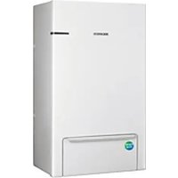


- AIR TO WATER HEAT PUMP
- INSTALLATION MANUAL
- SAFETY INFORMATION
- HANDLING THE BOX
- UNIT INSTALLATION
- PIPING INSTALLATION
- ELECTRICAL INSTALLATION
- SYSTEM CONFIGURATION
- CHARGING REFRIGERANT
- TROUBLESHOOTING
- TECHNICAL DATA
- (APPLICABLE IN COUNTRIES WITH SEPARATE COLLECTION SYSTEMS)
- GENERAL
- INSTALLING THE UNIT
- NOTE
- WARNING
- CAUTION OF IGNITION SOURCES
- LEAKAGE DETECTION AND REFRIGERANT RECOVERY
- LABELLING
- REFRIGERANT RECOVERY
- INSTALLATION LOCATION REQUIREMENT OF OUTDOOR UNIT
- ACCESSORIES
- PREPARING THE INSTALLATION OF THE OUTDOOR UNIT
- CHOOSING THE INSTALLATION LOCATION
- DECIDE THE INSTALLATION LOCATION REGARDING THE FOLLOWING CONDITION AND OBTAIN THE USER'S APPROVAL
- DO NOT INSTALL THE AIR TO WATER HEAT PUMP IN THE FOLLOWING LOCATIONS
- SAFETY ZONE
- WHEN INSTALLING 1 OUTDOOR UNIT
- WHEN INSTALLING MORE THAN 1 OUTDOOR UNIT
- CAUTION
- INSTALLING THE UNIT AT A LOCATION WITH STRONG WINDS
- INSTALLATION GUIDE AT THE SEASHORE
- SELECTING A LOCATION IN COLD CLIMATES
- HEAVY SNOW FALL AREA
- MOVING THE OUTDOOR UNIT
- MOVING THE OUTDOOR UNIT BY HOISTING
- MOVING THE OUTDOOR UNIT WITH A FORKLIFT
- MOUNTING THE OUTDOOR UNIT
- OUTDOOR UNIT DRAIN WORK
- GENERAL AREA
- ABOUT THE PIPING WORK
- CONNECTING THE WATER PIPES
- WATER CHARGING
- SETTING CAPACITY AND PRE-PRESSURE OF THE EXPANSION VESSEL
- PROTECTION OF THE WATER CIRCUIT AGAINST FREEZING
- FREEZE PROTECTION BY GLYCOL
- UNIT RESISTANCE AND PHE RESISTANCE BY GLYCOL CONCENTRATE
- FREEZING PROTECTION: ANTI-FREEZE VALVES
- OUTDOOR WATER PIPING INSULATION
- MINIMUM ACTIVE WATER VOLUME
- PRECAUTIONS WHEN CONNECTING THE ELECTRICAL WIRING
- ELECTRICAL WIRING DIAGRAM
- SPECIFICATION OF POWER CABLE
- PHASE
- TERMINAL BLOCK SPECIFICATION
- OUTDOOR WIRING
- OPEN THE SWITCH SIDE COVER
- REMOVE 2 SCREWS AND PULL THE PLATE TO THE LEFT
- IF THE PLATE IS ROTATED TO WHERE THE HOOK IS, IT WILL BE FIXED TO THE HOOK
- INSERT THE CABLES AT THE REAR OF THE UNIT, AND ROUTE THEM THROUGH THE FACTORY MOUNTED CABLE SLEEVES INTO THE SWITCH BOX
- POWER AND COMMUNICATION CABLE CONFIGURATION
- TO CONNECT THE POWER SUPPLY
- ROUTE THE CABLE THROUGH THE FRAME
- TO CONNECT THE COMMUNICATION CABLE
- CONNECTING A TEMP. SENSOR WIRE INTO DHW
- TO CONNECT EXTERNAL SENSORS
- TO CONNECT SMART GRID
- SETTING THE OUTDOOR OPTIONS VIA K-BUTTON TACTILE SWITCHES
- SETTING THE OPTION
- TESTING OPERATIONS
- FSV UPLOAD / DOWNLOAD
- HOW TO UPLOAD OR DOWNLOAD THE FIELD SETTING VALUES (EXAMPLE)
- IMPORTANT INFORMATION: REGULATION REGARDING THE REFRIGERANT USED
- REFRIGERANT CIRCUIT DIAGRAM
- PIPING & WIRING DIAGRAM
Brand : SAMSUNG
Model : AE080CXYBEK
Category : Heat pump