
AXAC-CH5 - Interface de caméra Axxess - Free user manual and instructions
Find the device manual for free AXAC-CH5 Axxess in PDF.


| Product Type | Multi-Port USB Charger |
| Model | AXAC-CH5 |
| Brand | Axxess |
| Number of USB Ports | 5 |
| Input Voltage | 100-240V AC, 50/60Hz |
| Output Current (Total) | 5A (1A per port) |
| Output Voltage | 5V DC |
| Power | 25W |
| Charging Technology | Smart IC for automatic device detection |
| Protection Features | Overcurrent, overcharge, short circuit, overheat |
| LED Indicator | Blue LED power indicator |
| Dimensions (L x W x H) | 3.5 x 2.0 x 1.2 inches (88 x 50 x 30 mm) |
| Weight | 4.2 oz (120 g) |
| Cable Length | 4.9 ft (1.5 m) detachable AC cord |
| Compatible Devices | Smartphones, tablets, Bluetooth headphones, and other USB devices |
| Material | Fireproof ABS plastic |
| Certifications | FCC, CE, RoHS |
| Operating Temperature | 32°F to 104°F (0°C to 40°C) |
| Warranty | 1-year limited |
| Package Contents | AXAC-CH5 charger, AC power cord, user manual |
Frequently Asked Questions - AXAC-CH5 Axxess
User questions about AXAC-CH5 Axxess
0 question about this device. Answer the ones you know or ask your own.
Ask a new question about this device
Download the instructions for your Interface de caméra in PDF format for free! Find your manual AXAC-CH5 - Axxess and take your electronic device back in hand. On this page are published all the documents necessary for the use of your device. AXAC-CH5 by Axxess.
USER MANUAL AXAC-CH5 Axxess
INTERFACE COMPONENTS
- AXAC-CH5 interface
- AXAC-CH5 interface harness
- AXAC-CH5 vehicle harness
Camera Data Interface w/Pre-Wired Harness Fits Select Chrysler Models 2013-2023
Visit AxxessInterfaces.com for more detailed information about the product and up-to-date vehicle specific applications
INTERFACE FEATURES
- Add multiple CAN-activated cameras with 4 camera inputs
- Includes AXAC camera interface and vehicle-specific harness
- Programmable 12-volt 5-amp switched output (configured through the Axxess Updater program)
- Reverse signal trigger generated via CAN bus communication of the vehicle
- Turn signal trigger generated via CAN bus communication of the vehicle
- 4 programmable camera control wires (configured through the Axxess Updater program)
- Can also be manually controlled and used along with an aftermarket radio
• VSS (Vehicle Speed Sense) input and output - Micro "B" USB updatable
APPLICATIONS
Dodge
Challenger (w/uConnect Radio) ..... 2015-2023
Charger (w/uConnect Radio)......2015-2023
Durango (w/uConnect Radio)......2014-2021
Jeep
Grand Cherokee
(w/8.4 uConnect Radio)....2014-2021
RAM
1500 (DS chassis code) 2019
1500/2500/3500....2013-2018
TABLE OF CONTENTS
Introduction 2
Configuration 2-4
Connections....5
Installation 6
Programming......6
Rebooting the U-Connect Radio 7
REQUIRED ITEMS
Update Cable: AXUSB-MCBL (sold separately)
Axxess Updater Program
TOOLS REQUIRED
- Crimping tool and connectors, or solder gun, solder, and heat shrink • Tape • Wire cutter
- Zip ties
ATTENTION: With the key out of the ignition, disconnect the negative battery terminal before installing this product. Ensure that all installation connections, especially the air bag indicator lights, are plugged in before reconnecting the battery or cycling the ignition to test this product.
NOTE: Refer also to the instructions included with the aftermarket accessory before installing this device.
INTRODUCTION
The AXAC-CH5 is a camera switching interface that provides up to (3) additional camera inputs to the factory radio, while still retaining the factory camera. With this interface a front camera, and/or side cameras, can be added to the factory radio. The cameras function automatically, no human interaction required, unless desired to do so. The interface can also be used if the vehicle doesn't come equipped with a backup camera, adding up to (4) cameras in this scenario. Axxess recommends cameras from the iBEAM product line for best results.
CONFIGURATION
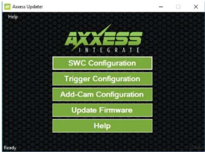
- Download and install the Axxess Updater available at: AxxessInterfaces.com
- Connect the AXUSB-MCBL update cable (sold separately) between the interface and the computer. The cable will connect into the micro-B USB port in the interface.
- Open the Axxess Updater and wait until the word Ready is listed in the bottom left of the screen.
- Select Add-Cam Configuration.
Continued on the next page
CONFIGURATION (CONT.)
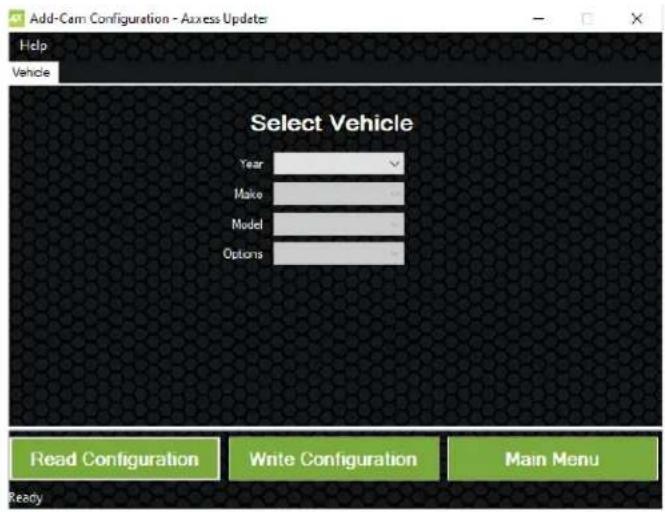
- Select the vehicle in the drop down list. A tab labeled Configuration will appear after the vehicle has been selected.

• Under Configuration, configure the (4) video trigger inputs to the desired settings. *
- Once all selections have been configured, press Write Configuration to save the settings.
- Unplug the update cable from the interface and computer.
* Refer to the following page for more information.
Continued on the next page
CONFIGURATION (CONT.)
Video trigger legend
- Disable (will turn off the input)
- Backup Camera (dedicated backup camera)
• Left Blinker (will be used for activation)
• Right Blinker (will be used for activation)
• Control 1 (positive trigger activation)
• Control 1 (negative trigger activation)
• Control 2 (positive trigger activation)
• Control 2 (negative trigger activation)
• Control 3 (positive trigger activation)
• Control 3 (negative trigger activation)
• Control 4 (positive trigger activation)
• Control 4 (negative trigger activation)
- Auto (Reverse -> Drive) will activate once that sequence is seen (only available for video trigger 4)
Other Settings
Switched 12v with
- Disable: Turns off the 12v from the camera 12v (Red) wire
- Accessory Out: Accessory Out:
Video trigger description
- Reverse camera: Dedicated by default to Video Trigger 1. Will activate the backup camera while the vehicle is in reverse.
- Left blinker: Activation of the left turn signal will activate the left camera.
- Right blinker: Activation of the right turn signal will activate the right camera.
- Auto (reverse -> drive): Available only for Video Trigger 4, when installing a front camera. With this feature selected, the camera will activate automatically once a reverse-then-drive sequence is seen from the vehicle. Example of this scenario would be while parallel parking the vehicle. As an alternative, a control wire can be used instead to manually activate the camera.
Note: Auto (Reverse -> Drive) will disable the camera once 15 MPH is reached. A control wire activated will also disable the camera.
Note: If the control wire is activated while driving, the camera will activate and deactivate during stop-and-go traffic. - Control 1-4 (positive or negative) trigger activation wires: Can be used as a positive or negative trigger to manually activate a camera via a toggle switch, or similar device.
Other settings
Switched 12V with: • Disable: On by default.
- Accessory Out: 12-volt out when CAN data is detected.
- Camera Active: 12-volt of a camera has been activated.
VSS out Function: • Disable: On by default.
- Camera Active: Active while camera is on.
CONNECTIONS
For models with a factory backup camera:
The camera signal will need to be interrupted and connected to the corresponding input/output RCA jacks from the interface.
- Connect the RCA jack from the AXAC-CH5 vehicle harness labeled “Camera input”, to the RCA jack from the AXAC-CH5 interface harness labeled “Camera output”.
- Connect the RCA jack from the AXAC-CH5 vehicle harness labeled "Camera output", to the RCA jack from the AXAC-CH5 Interface harness labeled "Camera 1".
- Disregard the following (3) wires: Blue/Green, Green/Blue, Red
For models without a factory backup camera:
- Connect the RCA jack from the AXAC-CH5 vehicle harness labeled "Camera input", to the RCA jack from the AXAC-CH5 interface harness labeled "Camera output".
- Connect the RCA jack from the AXAC-CH5 interface harness labeled "Camera 1", to the aftermarket backup camera.
- Disregard the RCA jack labeled "Camera output" from the AXAC-CH5 vehicle harness.
- Connect the Red wire from the AXAC-CH5 interface harness labeled "Camera 12V", to the power wire from the aftermarket backup camera.
- Disregard the following (2) wires: Blue/Green, Green/Blue
For models with an aftermarket radio:
- If the vehicle is equipped with a factory backup camera: Connect the RCA jack from the AXAC-CH5 vehicle harness labeled "Camera output", to the RCA jack from the AXAC-CH5 interface harness labeled "Camera 1".
- If the vehicle is not equipped with a factory backup camera: Connect the RCA jack from the AXAC-CH5 interface harness labeled “Camera 1”, to the aftermarket backup camera. Disregard the RCA jack labeled “Camera output” from the AXAC-CH5 vehicle harness.
- Disregard the RCA jack labeled "Camera input" from the AXAC-CH5 vehicle harness.
- From the AXAC-CH5 vehicle harness: Connect the Gray/Blue wire labeled "Reverse", to the Gray/Blue wire labeled "Control 1".
- Disregard the Red wire from the AXAC-CH5 vehicle harness labeled "Camera 12V".
- Connect the Red wire from the AXAC-CH5 interface harness labeled "Camera 12V", to the reverse trigger from the aftermarket radio.
Camera Input: Camera 1 Backup camera input
Camera 2 Left or right camera, user assignable
Camera 3 Left or right camera, user assignable
Camera 4 Front camera
Analaog control trigger wires: The (optional) analog control wires can be used with either a negative or positive trigger, depending on how they are configured in the Axxess Updater. These wires will only be used for manual control of the camera(s). Otherwise disregard them.
Control Wire Wire Color
Control 1 Gray/Blue
Control 2 Gray/Red
Control 3 Orange
Control 4 Orange/White
INSTALLATION PROGRAMMING
With the ignition cycled off:
- Remove the harness from the factory radio, then install the AXAC-CH5 vehicle harness in between.
- Connect the AXAC-CH5 vehicle harness to the AXAC-CH5 interface harness.
- Connect the AXAC-CH5 interface harness to the AXAC-CH5 interface.
- Make sure the camera(s) is connected to the appropriate input.
- Make sure the interface has been configured beforehand as shown in the Configuration section. Failure to configure the interface will result in the interface not functioning properly.

For models with a factory backup camera:
- Cycle the ignition on and wait until the LED in the interface comes on.
Note: If the LED doesn't come on within a few seconds, yet blinks instead, turn the key to the off position, disconnect the interface, check all connections, reconnect the interface, and then try again.
- Test all functions of the installation for proper operation.
For models without a factory backup camera:
Refer to next page (Rebooting the U-Connect Radio).
REBOOTING THE U-CONNECT RADIO
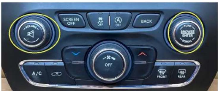
- The factory U-Connect Radio will require a reboot process to accept the aftermarket interface/or add a camera. Disconnecting the main harness to install a T-harness and repowering the radio may cause U-Connect Radio to program as a different model of vehicle than it was programmed to originally. Below are the different U-Connect initial Splash/Boot Up screens for vehicle types.
SPLASH/BOOT UP COLORS
Chrysler: Blue
Dodge/Ram: Red
Jeep: Orange
REBOOTING STEPS
- Turn the Key or Press Push to Start Button to the ACC position. DO NOT press brake on Push to Start vehicles.
- Press the Volume PWR/MUTE button and TUNE/ENTER button for 10-16 seconds, until the radio reboots.
- Let go once the radio reboots, now you have successfully rebooted your factory radio.

AXAC-CH5
INSTALLATION INSTRUCTIONS

Having difficulties? We're here to help.
Contact our Tech Support line at:
386-357-1187
Or via email at:
techsupport@metra-autosound.com
Tech Support Hours (Eastern Standard Time)
Monday - Friday: 9:00 AM - 7:00 PM
Saturday: 10:00 AM - 5:00 PM
Sunday: 10:00 AM - 4:00 PM


Metra recommends MECP certified technicians

COMPONENTES DE LA INTERFAZ
The (optional) analog control wires can be used with either a negative or positive trigger, depending on how they are configured in the Axxess Updater. These wires will only be used for manual control of the camera(s). Otherwise disregard them.
Cable de control Color de cable
Control 1 Gris con azul
- INTERFACE COMPONENTS
- CAMERA DATA INTERFACE W/PRE-WIRED HARNESS FITS SELECT CHRYSLER MODELS 2013-2023
- INTERFACE FEATURES
- APPLICATIONS
- DODGE
- JEEP
- RAM
- TABLE OF CONTENTS
- REQUIRED ITEMS
- TOOLS REQUIRED
- INTRODUCTION
- CONFIGURATION
- CONFIGURATION (CONT.)
- VIDEO TRIGGER LEGEND
- OTHER SETTINGS
- SWITCHED 12V WITH
- VIDEO TRIGGER DESCRIPTION
- CONNECTIONS
- FOR MODELS WITH A FACTORY BACKUP CAMERA
- FOR MODELS WITHOUT A FACTORY BACKUP CAMERA
- FOR MODELS WITH AN AFTERMARKET RADIO
- INSTALLATION PROGRAMMING
- WITH THE IGNITION CYCLED OFF
- REBOOTING THE U-CONNECT RADIO
- SPLASH/BOOT UP COLORS
- REBOOTING STEPS
- AXAC-CH5
- INSTALLATION INSTRUCTIONS
- COMPONENTES DE LA INTERFAZ
- CABLE DE CONTROL COLOR DE CABLE
Brand : Axxess
Model : AXAC-CH5
Category : Interface de caméra