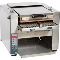
Ultra Max HCTE13M - Toaster STAR - Free user manual and instructions
Find the device manual for free Ultra Max HCTE13M STAR in PDF.


| Product Type | Toaster |
| Brand | STAR |
| Model | Ultra Max HCTE13M |
| Dimensions (W x D x H) | 30 cm x 20 cm x 25 cm |
| Weight | 1.8 kg |
| Power Supply | 220-240 V, 50/60 Hz, 850 W |
| Number of Slots | 2 |
| Browning Control | 7-level electronic browning control |
| Functions | Defrost, Reheat, Cancel, Lift & Look, Extra Lift |
| Self-Centering Racks | Yes, for even toasting |
| Removable Crumb Tray | Yes, easy to clean |
| Cord Storage | Yes, retractable cord |
| Material | Stainless steel and plastic |
| Cleaning Instructions | Unplug before cleaning. Wipe exterior with damp cloth. Empty crumb tray regularly. Do not immerse in water. |
| Safety Features | Automatic shut-off, cool-touch housing, anti-slip feet |
| Spare Parts Availability | Crumb tray, heating elements available via STAR service centers |
| Repairability Index | 8.5/10 (estimated based on design) |
| User Manual | Free PDF download at notice-facile.com |
Frequently Asked Questions - Ultra Max HCTE13M STAR
User questions about Ultra Max HCTE13M STAR
0 question about this device. Answer the ones you know or ask your own.
Ask a new question about this device
Download the instructions for your Toaster in PDF format for free! Find your manual Ultra Max HCTE13M - STAR and take your electronic device back in hand. On this page are published all the documents necessary for the use of your device. Ultra Max HCTE13M by STAR.
USER MANUAL Ultra Max HCTE13M STAR
2M-Z19028 Rev. E 10/13/2015
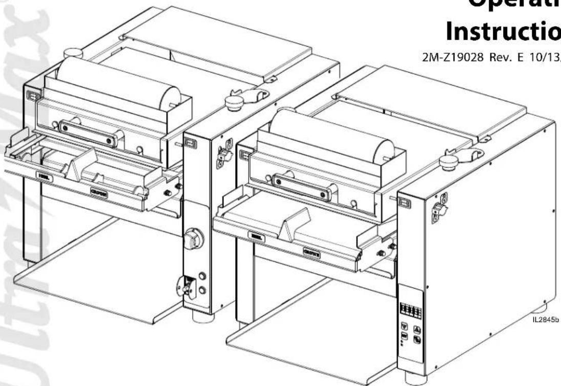
HCT13 & HCTE13
(Shown with optional butter wheel)

RETAIN THIS MANUAL FOR FUTURE REFERENCE NOTICE
Using any part other than genuine Star factory supplied parts relieves the manufacturer of all liability.
Star reserves the right to change specifications and product design without notice. Such revisions do not entitle the buyer to corresponding changes, improvements, additions or replacements for previously purchased equipment.
Due to periodic changes in designs, methods, procedures, policies and regulations, the specifications contained in this sheet are subject to change without notice. While Star International Holdings Inc., Company exercises good faith efforts to provide information that is accurate, we are not responsible for errors or omissions in information provided or conclusions reached as a result of using the specifications. By using the information provided, the user assumes all risks in connection with such use.
MAINTENANCE AND REPAIRS
Contact your local authorized service agent for service or required maintenance.
Please record the model number, serial number, voltage and purchase date in the area below and have it ready when you call to ensure a faster service.
Model No.
Serial No.
Voltage
Purchase Date
Authorized Service Agent Listing
Reference the listing provided with the unit
or
for an updated listing go to:
Website: www.star-mfg.com
E-mail customerservice@star-mfg.com
Service Help Desk
Business 8:00 am to 4:30 p.m. Central Standard Time
Hours:
Telephone: (314) 678-6303
Fax: (314) 781-2714
customerservice@star-mfg.com
Website:
www.star-mfg.com
Mailing Address: Star International Holdings Inc., Company 10 Sunnen Drive
St. Louis, MO 63143
U.S.A
TABLE OF CONTENTS
| Specifications | 1 |
| Features & Benefits | 2 |
| General Information | 3 |
| Uncrating & Inspecting | 3 |
| Electrical Connection | 3 |
| Assembly & Inspection | 4 |
| Toaster Settings | 4 |
| Daily Operation. | 5 & 6 |
| Cleaning | 7 |
| Troubleshooting | 8 |
| Maintenance | 9-10 |
| Warranty | 11 |
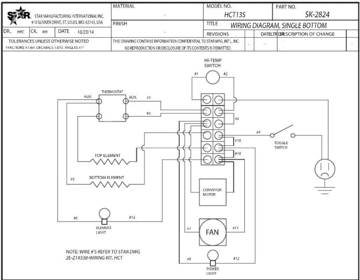
| Wiring Diagram. | 12-13 |
| Exploded View | 14-17 |
SPECIFICATIONS


Electrical Specifications
| Model Voltage Hz Ph Amps Watts Powercord | ||||||
| HCTE13M | 208V 60 | CEE7/VII1 | 13.5 2800 | 6-20P | ||
| 230V 50 | 12 2750 | |||||
| 240V | 60 | 12.5 3000 | 6-20P | |||
| HCTE13S | 208V | 12.25 | 2550 6-20P | |||
| 230V 50 | 10.511 | 2450 | CEE7/VII | |||
| 240V 60 | 2650 | 6-20P | ||||
| HCT13M | 208V 60 | CEE7/VII110.511 | 13.5 2800 | 6-20P | ||
| 230V 50 | 12 2750 | |||||
| 240V | 60 | 12.5 3000 | 6-20P | |||
| HCT13S | 208V | 12.25 | 2550 6-20P | |||
| 230V 50 | 2450 | CEE7/VII | ||||
| 240V 60 | 2650 | 6-20P | ||||
FEATURES & BENEFITS

| A Platen Height Indicator Indicates the height of the upper platen | |
| B Platen Support Bracket Keeps the upper platen in the up position, useful while cleaning | |
| C High Limit | Interrupts the heater tube connections if the air temperature in the control box exceeds 190°F (88°C). This limit switch can be reset manually by pushing the button in the center of the switch. |
| D Platen Height Knob Controls the height of the upper platen | |
| E Locking Platen Latch Keeps the upper platen in the down position. | |
| F Control Board Controls the conveyor speeds, turns unit on & off, & temperature settings. | |
| G Foot Silicone foot keeps unit firmly in place. | |
| H Crumb Tray Slide out crumb tray used to catch particles from falling | |
| I Toaster Chute Removable Chute returns product for easy access. | |
| J Conveyor Takes the heel and crown separately through their toasting process | |
| K Burn Guard Protects users from touching the conveyor belt | |
| L Durable Non-Stick Coated Sheet | Non-Stick surface between the upper platen and the product, allowing the product to slide easily through the toasting process. |
| M Upper Platen Assy | Heating surface designed to toast the product as it slides across the surface |
| N Optional Butter Wheel Saves time for preparing buns for toasting | |

GENERAL INFORMATION
This equipment is designed and sold for commercial use only by personnel trained and experienced in its operation and is not sold for consumer use in and around the home nor for use directly by the general public in food service locations.
Before using your new equipment, read and understand all the instructions & labels associated with the unit prior to putting it into operation. Make sure all people associated with its use understand the units operation & safety before they use the unit.
INSPECTION
UN-CRATING AND INSPECTING
Unpack the unit and components from the shipping container. Remove all visible packing material and those from inside the cooking chamber. If damage is discovered, file a claim immediately with the carrier that handled the shipment. Do not operate the unit if it was damaged during shipping. All shipping containers should be checked for freight damage both visible and concealed. This unit has been tested and carefully packaged to insure delivery of your unit in perfect condition. If equipment is received in damaged condition, either apparent or concealed, a claim must be made with the delivering carrier.
Concealed damage or loss - if damage or loss is not apparent until after equipment is unpacked, a request for inspection of concealed damage must be made with carrier within 15 days. Be certain to retain all contents plus external and internal packaging materials for inspection. The carrier will make an inspection and will supply necessary claim forms.
ELECTRICAL CONNECTION
Disconnect the unit from the power source before installing or removing any parts.
Be absolutely sure that the ground connection for the receptacle is properly wired. Do not connect equipment to power without proper ground connections. Improper grounding may result in personal injury or death.

CAUTION
Allow enough space around the toaster for adequate ventilation. Do not operate the unit without the crumb tray properly positioned. Overheating and poor toasting may occur. Read all labels on the unit and follow their instructions.

WARNING
Before making any electrical connection to this unit, check that the power supply is adequate for the voltage, amperage and requirements stated on the rating plate. A wiring diagram is included.

WARNING
DO NOT CUT OR REMOVE THIS PLUG OR THE GROUNDING PRONG FROM THE PLUG. FAILURE TO COMPLY MAY RESULT IN DEATH OR SERIOUS INJURY.

WARNING
CONNECT/PLUG UNIT INTO DEDICATED A. C. LINE ONLY SPECIFIED ON THE DATA PLATE OF THE UNIT.

CAUTION
SOME SURFACES ARE EXTREMELY HOT DURING OPERATION AND CARE SHOULD BE TAKEN WHILE USING THIS UNIT.
ASSEMBLY AND INSTALLATION
The unit was shipped fully assembled and ready to plug into a standard outlet specified for its voltage and amp draw. If improper electrical supply is determined, contact a qualified electrician prior to using the unit. Removal and replacement of the power cord and plug voids the warranty. For assistance, contact your local authorized service agent for service or required maintenance.
- Place the unit in its operating location.
- Wipe down the exterior with a damp cloth.
-
Place the Toaster Chute & Crumb Tray into position.
-
Unlock the Platen Latch and raise the platen, move the Platen Support Bracket to hold the platen in the up position. Sheet Retainer — Platen Suppo
-
Loosen the Sheet Retainer and install the non-stick sheet into position, and secure.
-
Lower the Platen and latch in place.
CAUTION
Failure to use non-stick sheets can lead to damaging the unit and a loss of warranty. The durable non-stick coated sheets are not a warranty item.
TOASTER SETTINGS
Before using the unit for the first time, test the pass time of the conveyor belt.
The pass time through the toaster should be between 16 to 20 seconds for standard setting.

- Turn unit ON and wait for it to complete the PRE-HEAT process.
- Set the Platen height by adjusting the two (2) Platen Height Knobs on top of the unit.
- Make sure the platen lock is on.
- Place a bun on the conveyor belt, cut side up, "HEEL" on one side and "CROWN" on the other.
IF TO DARK: Decrease TEMP.
IF TO LIGHT: Increase TEMP. or lower platen
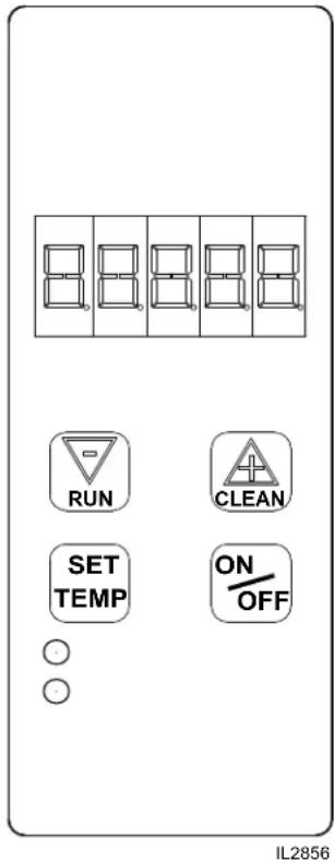
- Push and hold the "SET TEMP" button for three seconds.
- The display will flash the current top temperature setting.
- Using the and adjust the top heat to desired temperature (increments of 10° )
- Press the "SET TEMP" button again to change the bottom heat setting.
- Using the and adjust the bottom heating setting (0 - 10).
- Press the "SET TEMP" button again to save the settings and exit program mode.
CHANGING CONVEYOR SPEED
- Push and hold the and for three seconds
- Using the and adjust the motor speed to the desired setting (1 through 99)
- Press the "SET TEMP" button to exit the program
CHECK TEMPERATURE SETTING
- Press the "SET TEMP" button to check the platen temperature.
CLEAN MODE
-
Press the "CLEAN" button to enter the clean mode
a. Elements will be turned OFF and the belt will continue to run
b. The screen will flash CLEAN and WAIT.
c. When the platen has lowered to a safe temperature the screen will flash CLEAN and READY. -
Press the "ON/OFF" button to exit the clean mode.
CHANGING BUN THICKNESS SETTING
- Set the "Height Adjustment Knobs" to their desired settings.
- Turn unit ON, allow to warm-up before proceeding.
- Place buns on the conveyor, cut side up.
- Toasted buns will drop down the toaster chute.
- Turn the "Height Adjustment Knobs" to lower the platen for darker buns, raise for lighter buns.

CERTAIN SURFACES ARE EXTREMELY HOT DURING OPERATION AND CARE SHOULD BE TAKEN WHILE USING THIS UNIT.
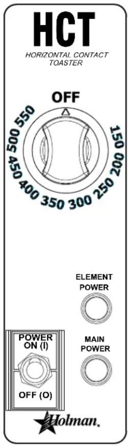
- Turn the Power Switch to the "ON" position
- The conveyor belt will begin to move.
- Using Temperature Knob, move it from the "OFF" position to your desired temperature.
- The Element Power Light will turn "ON" when the unit is calling for heat. When your desired temperature is reached, the light will turn "OFF". Wait for the Element Power Light to cycle twice before using.
- When finished using, turn the Temperature Knob to the "OFF" position, but leavet the Power Switch in the "ON" position to allow the cooling fan to run.
- Once cooled, move the switch to the "OFF" position.
CHANGING CONVEYOR SPEED
Changing conveyor speed is only capable on the electronically controlled units.

CERTAIN SURFACES ARE EXTREMELY HOT DURING OPERATION AND CARE SHOULD BE TAKEN WHILE USING THIS UNIT.
IL2912
CHANGING BUN THICKNESS SETTING
- Set the "Height Adjustment Knobs" to their desired settings.
- Turn unit ON, allow to warm-up before proceeding.
- Place buns on the conveyor, cut side up.
- Toasted buns will drop down the toaster chute.
- Turn the "Height Adjustment Knobs" to lower the platen for darker buns, raise for lighter buns.
Height Adjusting Knob

Height Indicator
CLEANING
Preventive maintenance for your Ultra-Max Contact Toaster consists of the following recommended cleaning procedures. To keep your toaster in top operating condition, these steps should be performed daily or weekly as indicated.
Daily Cleaning
- MANUAL: Turn the temp knob to the "OFF" position, and the power switch in the "ON" position.
ELECTRONIC: Press and hold the CLEAN button to enter cleaning mode.
a. The screen will flash "CLEAN" "WAIT" while the unit cools down to a safe temperature.
b. Unlock platen using knob on side, raise the platen and prop open to speed up cool down.
Always remove Butter before raising platen if used.
c. The screen will flash "CLEAN" "READY" when the unit has cooled to a safe temperature.
IMPORTANT: Allow the unit to cool before attempting to clean it.
- Wipe down moving belt with mild detergent and damp cloth. (an abrasive pad can be used on metal belt).
- Wipe down exterior of toaster with mild detergent and damp cloth.
- Remove non-stick sheet and clean with mild detergent and damp cloth. (If excess buildup is unable to be removed and causing buns to stick to the sheet, a new sheet may need to be installed.)
- Remove crumb tray and toast slide and wash in a sink with mild detergent.
- Dry and return crumb tray, toast slide, and non-stick sheet back into position.
- Turn the power switch to the "OFF" position, until you need

DO NOT IMMERSE OR LET THE UNIT STAND IN WATER. DO NOT HOSE DOWN THE UNIT OR THE TABLE/COUNTER IF THE UNIT IS ON THE TABLE/COUNTER.
KEEP AWAY FROM RUNNING WATER.

DO NOT use caustic cleaners on any surface of the unit, conveyor belt or Durable Non-Stick Coated Sheets

TROUBLESHOOTING GUIDE
A. Unit Will Not Heat, Conveyor Belt Will Not Move.
1) Be sure the main circuit breaker is switched to the ON
2) Check to see if the toaster is plugged in and all controls are turned to the ON position.
B. Unit Has Heat Only On One Side, Conveyor Belt Turns Freely.
1) Contact your local service agent,, as heating element may need replacing.
C. Conveyor Will Not Turn, Unit Heats Properly.
To check for mechanical binding:
1) DISCONNECT UNIT FROM POWER SOURCE.
3) Remove 4 screws on the back of the toaster and remove back panel.
4) Remove the right side panel.
5) Loosen the four screws that hold the drive motor in place.
6) Slide the motor up allowing the drive chain to be removed from the sprockets.
8) Re-install the rear and side panels.
7) Move the conveyor belt by hand to check for mechanical binding. If conveyor moves freely, contact your local service agent,, as the drive motor and/or speed control may need replacing.
D. Heat Limit Switch (Reset)
Your Ultra-Max contact toaster is equipped with an automatically activated heat limit switch that interrupts the heater tube connections if the ambient temperature in the control box exceeds 190° F ( 88° C). This switch can be reset manually by pushing the red button located behind the right side panel as shown in the Components Illustration on Page 2.
1) DISCONNECT UNIT FROM POWER SOURCE.
2) Check to see if air intake area in the bottom center of the control box cover is free of dust, grease or other obstructions.
3) Check if crumb tray is in place.
4) If no obstructions to the airflow can be found contact your local service agent, for assistance.
E. Conveyor Turns At One Speed Regardless Of Speed Control Setting
(HCTE models only).
1) Contact your local service agent,, as speed control should be replaced.
F. Product Sticking To Conveyor Or Slide
Your Ultra-Max Contact Toaster is designed to toast product that is current room temperature.
DO NOT attempt to put frozen, refrigerated material in the toaster.
Doing so may cause it to come out doughy or very moist, as well as possibly sticking to parts of the unit. Follow the cleaning procedures.
MAINTENANCE PROCEDURES
A. Replacing the Bottom Element
1) DISCONNECT UNIT FROM POWER SOURCE.
2) Remove the side panels and bottom panel.
3) Remove element wire from terminal block connection, keeping top and bottom wires separate.
4) Lift element retainers by loosening retaining screws and removing the retainer plate up.
5) Gently, pull defective element out of unit.
6) Gently, put new element into unit.
7) Slide the retainer back into place. Tighten the screw to secure the retainer in place over the ends of the elements.
B. Replacing the Fan Motor
1) DISCONNECT UNIT FROM POWER SOURCE.
2) Remove the toaster slide.
3) Remove screws from the bottom panel.
4) Unplug power supply cord from fan motor.
5) Remove (4) screws, which hold fan motor and grill to bottom of unit and remove fan.
6) Put replacement motor and grill in place and secure to the bottom of unit with screws.
7) Reconnect power supply cord to fan motor.
8) Replace bottom panel. Fasten with screws removed in step 2.
C. Replacing the Belt Drive Motor
1) DISCONNECT UNIT FROM POWER SOURCE.
2) Remove the right side and bottom panels.
3) Remove sprocket from motor shaft, using an Allen wrench and loosening the set-screw.
4) Remove the wire from terminal block connecting the drive motor to internal wiring. On units rated 208 or 240 volts, note which color leads are being used for these connections and which lead is capped with white tape. The new motor should use the same arrangement.
5) Remove screws holding motor in place and remove motor from unit.
6) Put new motor in place and attach loosely with mounting screws.
7) Replace sprocket on motor shaft.
NOTE The two sprockets should line up parallel with each other, so the chain does not twist any during operation. Also the hub gets installed closets to the motor.
8) Slide motor until the drive chain has about 1/4" slack when lightly pushed at the center of its top open run. See chain tensioning illustration.
9) Tighten screws to secure motor.
10) Rewire leads same as removed in step 4.
11) Replace previously removed panels.
D. Clean the Air Intake (Once A Week)
1) DISCONNECT UNIT FROM POWER SOURCE.
2) Place unit on its backside.
3) Use a vacuum cleaner and or a damp cloth to clean the air intake.
E. Lubricate the Chain & Sprockets (Every 6 Months) 1) DISCONNECT UNIT FROM POWER SOURCE.
2) Remove enclosure exposing chain drive.
3) While wearing rubber gloves and using an extreme pressure, synthetic chain lubricant with a temperature range up to 400° F ( 204° C) lubricate chain and sprockets. Apply liberally. This grease is available as part no. 1L-Z12397.
4) Replace enclosure, Reconnect power source and test unit.

Chain Tension
MAINTENANCE continued
REMOVING & REPLACING SILICONE BELT
- Disconnect unit from power allow to cool before beginning process.
- Remove guard from in front of the belt.
- Rotate belt by hand until belt seam is visible.
- The Idler Shaft is spring loaded. Press on the front idler shaft to remove tension from the belt. (Continuous pressure is required).
- Pull splicing rod from belt.
- Carefully release pressure from idler shaft so the roller is not propelled from the unit by the springs.
- Installation is similar to removal. Feed the belt around the drive shaft and idler shaft rollers making sure the tracking guide on the backside of the belt is seated in the roller grooves.
- Press the front roller to create slack in the belt.
- Feed the splicing rod through the two ends of the belt.
- Remove pressure from roller and install belt guard.
- Plug unit back into outlet and test for proper operation.

Above: Removing and Installing Silicone Belt

DISCONNECT THE POWER SUPPLY BEFORE SERVICING OR CLEANING THIS OVEN. SAFEGUARD THE POWER SO IT CANNOT BE ACCIDENTALLY RESTORED. FAILURE TO DO SO COULD RESULT IN DISMEMBERMENT, ELECTROCUTION, OR FATAL INJURY.
THOROUGHLY INSPECT YOUR UNIT ON ARRIVAL
This unit has been tested for proper operation before leaving our plant to insure delivery of your unit in perfect condition. However, there are instances in which the unit may be damaged in transit. In the event you discover any type of damage to your product upon receipt, you must immediately contact the transportation company who delivered the item to you and initiate your claim with same. If this procedure is not followed, it may affect the warranty status of the unit.
LIMITED EQUIPMENT WARRANTY
All workmanship and material in Star products have a one (1) year limited warranty on parts & labor in the United States and Canada. Such warranty is limited to the original purchaser only and shall be effective from the date the equipment is placed in service. Star's obligation under this warranty is limited to the repair of defects without charge, by the factory authorized service agency or one of its sub-agencies. Models that are considered portable (see below) should be taken to the closest Star service agency, transportation prepaid.
Star will not assume any responsibility for loss of revenue.
On all shipments outside the United States and Canada, see International Warranty.
* The warranty period for the Ultra-Max, Hot Plates, Griddles, Charbroilers is (3) years parts & labor.
* The warranty period for the Star-Max, Charbroilers, Griddles, Hot Plates, Fryers & Finishing Oven is (2) years parts & labor.
* The warranty period for the JetStar six (6) ounce & Super JetStar eight (8) ounce series popcorn machines is two (2) years.
* The warranty period for the Chrome-Max Griddles is five (5) years on the griddle surface. See detailed warranty provided with unit.
* The warranty period for Dura-Tec coatings is one year under normal use and reasonable care. This warranty does not apply if damage occurs to Dura-Tec coatings from improper cleaning, maintenance, use of metallic utensils, or abrasive cleaners, abrasive pads, product identifiers and point-of-sale attachments, or any other non-food object tha comes in continuous contact with the roller coating. This warranty does not apply to the “non-stick” properties of such materials.
This warranty does not apply to "Special Products" but to regular catalog items only. Star's warranty on "Special Products" is six (6) months on parts and ninety (90) days on labor.
This warranty does not apply to any item that is disassembled or tampered with for any purpose other than repair by a Star Authorized Service Center or the Service Center's sub-agency.
This warranty does not apply if damage occurs from improper installation, misuse, wrong voltage, wrong gas or operated contrary to the Installation and Operating instructions.
This warranty is not valid on Conveyor Ovens unless a "start-up/check-out" has been performed by a Factory Authorized Technician.
PARTS WARRANTY
Parts that are sold to repair out of warranty equipment are warranted for ninety (90) days. The part only is warranted, the labor to replace the part is NOT warranted.
SERVICES NOT COVERED BY WARRANTY
-
Travel time and mileage rendered beyond the 50 mile radius limit
-
Mileage and travel time on portable equipment (see below)
-
Labor to replace such items that can be replaced easily during a daily cleaning routine, ie; removable kettles on fryers, knobs, grease drawers on griddles, etc.
-
Installation of equipment
-
Damages due to improper installation
-
Damages from abuse or misuse
-
Operated contrary to the Operating and Installation Instructions
-
Cleaning of equipment
-
Seasoning of griddle plates
-
Voltage conversions
-
Gas conversions
-
Pilot light adjustment
-
Miscellaneous adjustments
-
Thermostat calibration and by-pass adjustment
-
Resetting of circuit breakers or safety controls or reset buttons
-
Replacement of bulbs
-
Replacement of fuses
-
Repair of damage created during transit, delivery, & installation OR created by acts of God
PORTABLE EQUIPMENT
Star will not honor service bills that include travel time and mileage charges for servicing any products considered "Portable" including items listed below. These products should be taken to the Service Agency for repair:
* The Model 510FD, 510FF Fryer.
* The Model 526TOA Toaster Oven.
* The Model J4R, 4 oz. Popcorn Machine.
* The Model 518CMA & 526CMA Cheese Melter.
* The Model 12MC & 15MC & 18MCP Hot Food Merchandisers.
* The Model 12NCPW & 15NCPW Nacho Chip/Popcorn Warmer.
* All Hot Dog Equipment except Roller Grills & Drawer Bun Warmers.
* All Nacho Cheese Warmers except Model 11WLA Series Nacho Cheese Warmer.
* All Condiment Dispensers except the Model HPD & SPD Series Dispenser.
* All Specialty Food Warmers except Model 130R, 11RW Series, and 11WSA Series.
* All QCS/RCS Series Toasters except Model QCS3 & RCS3 Series.
* All Fast Steamer Models except Direct Connect Series.
ALL:
* Pop-Up Toasters
* Butter Dispensers
* Pretzel Merchandisers (Model 16PD-A Only)
* Pastry Display Cabinets
* Nacho Chip Merchandisers
* Accessories of any kind
* Snecze Guards
* Pizza Ovens (Model PO12 Only)
* Heat Lamps
* Pumps-Manual
The foregoing warranty is in lieu of any and all other warranties expressed or implied and constitutes the entire warranty.
FOR ASSISTANCE
Should you need any assistance regarding the Operation or Maintenance of any Star equipment; write, phone, fax or email our Service Department. In all correspondence mention the Model number and the Serial number of your unit, and the voltage or type of gas you are using.
| STAR. STAR MANUFACTURING INTERNATIONAL INC.#10 SUNNEN DRIVE, ST. LOUIS, NO. 63143, USA | MATERIAL- | MODEL NO.HCTE | PART NO.SK-2798 | |||||
| FINISH | TITLE WIRING DIAGRAM, PARALLEL BOTTOM | |||||||
| DR. MRC | CK. MH | DATE 7/11/14 | REVISIONS | LTR | DATE | DESCRIPTION OF CHANGE | DR | |
| TOLERANCES UNLESS OTHERWISE NOTEDFRACTIONS ±1/64 DECIMALS ±0.015 ANGLES ±1" | THIS DRAWING CONTAINS INFORMATION CONFIDENTIAL TO STAR MFG. INT'L. INC.NO REPRODUCTION OR DISCLOSURE OF ITS CONTENTS IS PERMITTED. | - | - | - | - | - | ||

| STAR. STAR MANUFACTURING INTERNATIONAL INC.#C SUMEN DRIVE, ST. LOUG, NO. 61143, USA | MATERIAL- | MODEL NO.HCTE | PART NO.SK-2799 | |||||
| FINISH- | TITLE WIRING DIAGRAM, SINGLE BOTTOM | |||||||
| DR. MRC | CK. MH | DATE 7/11/14 | REVISIONS | LTR | DATE | DESCRIPTION OF CHANGE | DR | |
| TOLERANCES UNLESS OTHERWISE NOTEDFRACTIONS ±1/64 DECIMALS ±015 ANGLES ±1" | THIS DRAWING CONTAINS INFORMATION CONFIDENTIAL TO STAR MFG. INTL. INC.NO REPRODUCTION OR DISCLOSURE OF ITS CONTENTS IS PERMITTED. | - | - | - | - | |||



Model: HCTE & HCT Contact Toasters w/electronic & manual controls

| Model: HCTE13 & HCT13 Contact Toaster | ||||
| Fig No Part No Quantity Description Application | ||||
| 1 HC-C | T0018 Optional Butter | Wheel Weldment | ||
| 2 HC-C | T0017 Optional Butter | Wheel Base Weldment | ||
| 3 2I-05 | 07-0013 1 BOOT SWITCH HCT13 | |||
| 4 2M-Z | 8461 1 LABEL, POWER, ON & OFF | HCT13 | ||
| 5 Z1-70 | 07-0343 1 SWITCH GUARD HCT13 | |||
| 6 | 2J-31157 | 1 | LIGHT SIGNAL RED, MAIN POWER | HCT13 |
| 7 | 2J-31157 | 1 | LIGHT SIGNAL RED, ELEMENT PWR | HCT13 |
| 8 2R-Z | 8145 | 1 KNOB, SG 1.75 X .25 SHAFT | HCT13 | |
| 9 2M-Z | 9266 1 LABEL, HCT | HCT13 | ||
| 10 | 2T-Z18396 | 1 | THERMOSTAT, 150-550°F | HCT13 |
| 11 | 2E-30330 | 1 | SWITCH ON OFF TOGGLE 20A | HCT13 |
| 12 | 2M-Z18207 1 LABEL, HCTE | HCTE13 | ||
| 13 | 2J-Z17717 | 1 | ELECTRONIC CONTROL SPEC | HCTE13 |
| 14 | 2U-200592 | 1 | QCSE PWRBRD,W/RIBBONCABLE | HCTE13 |
| 15 | HC-CT0005 | 1 | PLATEN COVER ASY | |
| 16 | 2K-Z17714 | 2 BUSHING, OUTER | ||
| 17 | 2C-6517 | 6 NUT 1/4-20 HEX STL NP | ||
| 18 | 2A-Z17716 | 2 SUPPORT, 1/4-20 X 11/32 | ||
| 19 | 2A-Z17727 | 2 | SPACER, 5/8"OD X 0.266"ID | |
| 20 | 2R-Y2830 | 1 | HANDLE HARRY DAVIES 4560 | |
| 21 | 2C-Z18503 | 2 SCREW, SOCKET CAP 1/4-20 | ||
| 22 | HC-Z17713 | 1 RETAINER, PTFE SHEET | ||
| 23 | 2A-Z17712 | 3 THUMBSCREW 8-32 X .375 | ||
| 24 | HC-Z17724 | 1 THERMOPROBE BRKT | HCTE13 | |
| 25 | HC-Z17711 1 ELEMENT COVER | |||
| 26 | 2N-Z17710 | 1 | ELEMENT, METAL 2300W 240V | 240V, 230V |
| 2N-Z17749 | ELEMENT, METAL 2300W 208V | 208V | ||
| 27 | 2F-Z17708 | 1 | 13" TOP CASTING | |
| 28 | 2A-Z18504 | 1 SPACER, 3/8IN X 1/4IN | ||
| 29 | 2C-Y7595 | 1 | BOLT 1/4-20X1/2 THS STL | |
| 30 | 2H-Z18588 | 1 PTFE SHEET, 0.003 TK | ||
| 31 | HC-CT0006 | 1 | BACK PANEL ASY | |
| 32 | 2C-Z10075 | 1 SCREW-1/4-20X3/8 SS THS | ||
| 33 | HC-Z17737 | 1 | PLATEN SUPPORT BRKT | |
| 34 | 2E-200566 | 1 SWITCH,RSET,0796-190F TRPS | ||
| 35 | 2A-CT0015 | 1 | BELT DRIVE SHAFT ASSEMBLY | HCTE13M |
| 2A-CT0015SB | HCTE13S | |||
| 36 | HA-112261 | 2 | BEARING ASSY PTFE/BRONZE | |
| 37 | 2C-Z6929 | 34 | NUT, 10-24 KEPS SS | |
| 38 | 2P-200646 | 1 SPROCKET, 25B20 X 5/16 | ||
| 39 2P-150013 1 DRIVE CHAIN #25 ROLLER | ||||
| 40 2P-200648 1 SPROCKET | 25B32 X 5/16 | |||
| 41 2E-Z17514 1 SENSOR, SPEED HCTE13 | ||||
| 42 HC-CT0008 1 SPEED CONTROL BRKT ASY HCTE13 | ||||
| 43 2U-Z9657 1 MOTOR,11RPM-CW,NEW STYLE | ||||
| 44 2K-Y3240 1 BUSHING HEYCO SR 17-2 | ||||
| 45 | 2E-Z10406 | 1 | TERMINAL BLOCK 4 POS | HCTE13M |
| 2E-Z14254 | TERMINAL BLOCK 6-POLE | HCT13 | ||
| 46 HC-CT0013 1 RIGHT ADJUSTMENT BRKT ASY | ||||
| 47 HC-CT0014 1 PLATEN LATCH ASY | ||||
| 48 2M-Z18513 | 1 LABEL, UNLOCK SYMBOL | |||
| 49 2M-Z18512 | 1 LABEL, LOCK SYMBOL | |||
| 50 2R-Z17729 | 1 KNOB, 1-1/4 X 5/8 X 1/2 | |||
| 51 HC-Z17742 | 1 PANEL, RIGHT COVER | |||
| 52 2C-6349 | 24 SCREW #8X3/8 B THP STL NP | |||
| 53 2R-200562 1 FAN GUARD | ||||
| 54 HC-Z17740 | 1 MOTOR HOUSING COVER | |||
| 55 2U-200561 1 MOTOR, FAN 240V 23BTM | ||||
| 56 2R-Z18201 | 4 FOOT 1.69X1 SIL 1/4 20 | |||
| 57 HC-Z17723 | 1 TOAST SLIDE | |||
| 58 HC-Z17736 | 1 CRUMB TRAY | |||
| 59 2P-Z18587 2 BEARING SPRING 2IN | ||||
| 60 2P-200700 2 BRG SPRING LOADED | ||||
| 61 2C-2559 | 4 NUT 10-24 ACHD BR NP | |||
| 62 2M-Z17750 | 1 LABEL, CROWN | |||
| 63 2M-Z17735 | 1 LABEL, HEEL | |||
| 64 HC-CT0009 1 BELT GUARD ASM | ||||
| 65 | 2A-CT0016 | 1 BELT IDLER SHAFT ASSEMBLY | HCTE13M | |
| 2A-CT0016SB | HCTE13S | |||
| 66 2K-200464 2 BUSHING, WIRE RING 7/8" | ||||
| 67 2M-Z18258 | 2 LABEL, SCALE | |||
| 68 2A-Z17720 8 SPACER-.375"OD X .192"ID | ||||
| 69 2V-Z17744 1 PLATEN SUPPORT | ||||
| 70 HC-CT0012 1 LEFT ADJUSTMENT BRKT ASY | ||||
| 71 HC-CT0007 2 ELEMENT SUPPORT ASY | ||||
| 72 HC-Z17731 | 1 ELEMENT RETAINER | |||
| 73 HC-Z17741 | 1 PANEL, LEFT COVER | |||
| Fig No Part | No Quantity Description | Application | ||
| 74 | 2N-Z17718 1 ELEMENT, METAL 35 | DW 240V HCTE13S | ||
| 2N-Z17718 2 ELEMENT, METAL 35 | DW 240V HCTE13M | |||
| 75 2C-18 | 10 16 WASHER 3/16 | BURR STL NP | ||
| 76 2K-Z17715 2 BUSHING, INNER | ||||
| 77 HC-Z16924 1 SHAFT ACCESS COVER PLATE | ||||
| 78 2A-CT0011 | 2 ADJUSTMENT KNOB ASY | |||
| NI | 2E-Z17719 1 TYPE | K PROBE | HCTE13 | |
| NI | 2B-Z17743 1 CONVEYOR BELT CG | 10 X.062 | ||
| NI | PS-CT0034 | 1 SILICONE BELT, 13" X 41.04 | ||
| NI | HA-120244 | 1 | CORDSET ASSY QCS1-230C | 230V |
| NI | HA-120245 | 1 CORDSET ASSY NEMA 6-20P 208,240V | ||
- RETAIN THIS MANUAL FOR FUTURE REFERENCE NOTICE
- MAINTENANCE AND REPAIRS
- AUTHORIZED SERVICE AGENT LISTING
- SERVICE HELP DESK
- FEATURES & BENEFITS
- GENERAL INFORMATION
- INSPECTION
- UN-CRATING AND INSPECTING
- ELECTRICAL CONNECTION
- CAUTION
- WARNING
- ASSEMBLY AND INSTALLATION
- TOASTER SETTINGS
- CHANGING CONVEYOR SPEED
- CHECK TEMPERATURE SETTING
- CLEAN MODE
- CHANGING BUN THICKNESS SETTING
- CLEANING
- DAILY CLEANING
- DO NOT IMMERSE OR LET THE UNIT STAND IN WATER. DO NOT HOSE DOWN THE UNIT OR THE TABLE/COUNTER IF THE UNIT IS ON THE TABLE/COUNTER
- TROUBLESHOOTING GUIDE
- UNIT WILL NOT HEAT, CONVEYOR BELT WILL NOT MOVE
- UNIT HAS HEAT ONLY ON ONE SIDE, CONVEYOR BELT TURNS FREELY
- CONVEYOR WILL NOT TURN, UNIT HEATS PROPERLY
- HEAT LIMIT SWITCH (RESET)
- CONVEYOR TURNS AT ONE SPEED REGARDLESS OF SPEED CONTROL SETTING
- PRODUCT STICKING TO CONVEYOR OR SLIDE
- MAINTENANCE PROCEDURES
- MAINTENANCE CONTINUED
- REMOVING & REPLACING SILICONE BELT
- THOROUGHLY INSPECT YOUR UNIT ON ARRIVAL
- LIMITED EQUIPMENT WARRANTY
- PARTS WARRANTY
- SERVICES NOT COVERED BY WARRANTY
- PORTABLE EQUIPMENT
- ALL
- FOR ASSISTANCE
Brand : STAR
Model : Ultra Max HCTE13M
Category : Toaster