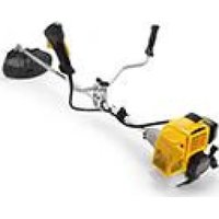
SBC 635 KD - Lawn mower STIGA - Free user manual and instructions
Find the device manual for free SBC 635 KD STIGA in PDF.


| Product Type | Lawn Mower |
| Brand | STIGA |
| Model | SBC 635 KD |
| Cutting Width | 635 mm (25 in) |
| Engine Type | Kawasaki 4-stroke petrol engine |
| Engine Power | Approx. 6.0 HP (4.5 kW) |
| Fuel Tank Capacity | 2.0 L |
| Self-Propelled | Yes, rear-wheel drive |
| Cutting Height Adjustment | Central lever, 7 positions (25-75 mm) |
| Grass Catcher | 80 L fabric collector bag |
| Mulching Capability | Yes, with optional mulching plug |
| Weight | Approx. 45 kg |
| Dimensions (LxWxH) | 1700 x 650 x 1050 mm |
| Blade Type | Two-blade cutting system |
| Safety Features | Blade brake clutch, operator presence control |
| Maintenance Interval | Oil change every 25 hours, air filter every 10 hours |
| Spare Parts Availability | Full range available from authorized dealers |
| Warranty | 2 years limited warranty |
Frequently Asked Questions - SBC 635 KD STIGA
User questions about SBC 635 KD STIGA
0 question about this device. Answer the ones you know or ask your own.
Ask a new question about this device
Download the instructions for your Lawn mower in PDF format for free! Find your manual SBC 635 KD - STIGA and take your electronic device back in hand. On this page are published all the documents necessary for the use of your device. SBC 635 KD by STIGA.
USER MANUAL SBC 635 KD STIGA
MANUAL DE INSTRUÇÕES
| [91] | 118802318/0 (M10 x 1,25 sx female) | |||||||||||
| [92] | 118802323/0 | |||||||||||
| [93] | X | X | X | X | X | X | X | X | X | X | X | |
| [91] | 118802314/0 | |||||||||||
| [92] | 118802323/0 | |||||||||||
| [93] | X | X | X | X | X | O | O | O | O | O | O | |
| [91] | 118802316/0 | |||||||||||
| [92] | 118802323/0 | |||||||||||
| [93] | O | O | O | O | O | X | X | X | X | X | X | |
| [91] | 118802315/0 | |||||||||||
| [92] | 118802323/0 | |||||||||||
| [93] | 0 | 0 | 0 | 0 | 0 | 0 | 0 | 0 | 0 | 0 | 0 | |










24
II
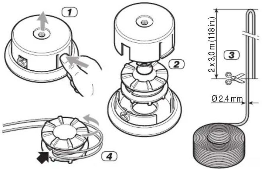
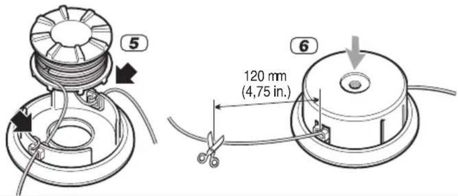

TABLE OF CONTENTS
Getting to know the machine 10
Safety regulations 11
Operating instructions 13
- Machine assembly 13
- Preparing to work 16
- Using the machine 17
- Operating modes and work techniques ... 18
- Routine maintenance 20
- Extraordinary maintenance 22
- Diagnostics 22
HOW TO READ THE MANUAL
Certain paragraphs in the manual contain particularly significant information and are marked with various levels of highlighting with the following meaning:
NOTE or
IMPORTANT These give details or further information on what has already been said, and aim to prevent damage to the machine or cause other damage.
WARNING! Non-observance will result in the risk of injury to oneself or others.
DANGER! Non-observance will result in the risk of serious injury or death to oneself or others.
GETTING TO KNOW THE MACHINE
NOTE - The images corresponding to the references are found on page 2 of this manual.
DESCRIPTION OF THE MACHINE AND ITS RANGE OF USE
This machine is a garden tool, and precisely a portable brush cutter/grass edge trimmer with combustion engine for home use.
The machine is essentially composed of an engine which, employing a transmission shaft enclosed in a tube and an angle transmission, drives a cutting device that is configured in various ways for carrying out different functions. The operator is able to sustain the machine with the aid of a harness and can operate the main controls, always keeping a safe distance from the cutting device.
Intended use
This machine was designed and manufactured for:
- cutting grass and non-woody vegetation, using a nylon line (e.g. around the edges of lawns, flowerbeds, walls, fences and small grassy areas to tidy up the cutting done using a mower).
- cutting tall grass, dry branches, twigs and woody shrubs of up to 2 cm diameter, with the aid of metal or plastic blades.
Improper use
Any other use differing from the above mentioned ones could be hazardous and harm people and/or damage things. Examples of improper use may include, but are not limited to:
– using the machine for sweeping;
- trimming hedges or other jobs in which the cutting device is not used on ground level;
-pruningtrees;
- using the machine with the cutting device above the operator's belt level;
- use of the machine for cutting non-plant material;
– use of the machine by more than one person.
IDENTIFICATION LABEL AND MACHINE COMPONENTS
- Acoustic power level
- Conformity marking
- Year of manufacture
- Manufacturer's reference model
- Serial number
- Name and address of manufacturer
- Emission number
-
Article code
-
Power unit
- Drive tube
-
Cutting device a. 3-point blade b. Cutting line head
-
Cutting device guard
-
Front handgrip
-
Guard
-
Handle bar
-
Rear handgrip
-
Connection point (of the harness)
-
Harness
a. with single belt
b. with double belt
c. with backpack - Angle transmission
- Blade protection (for transport)
- Spark plug
- Engine stop switch
- Throttle control
- Throttle lockout
- Starter grip
- Choke
- Primer
- Throttle shutter (if provided)
- Fuel mixture tank cap
The example of the conformity declaration is found in the penultimate page of the manual.
DESCRIPTION OF EXPLANATORY SYMBOLS (where applicable)
- Fuel mixture tank
- Engine stop switch positions
a = stop
b = running
- Choke
- Cutting device with adequate protection
- Cutting device rotation direction
SAFETY REQUIREMENTS
Your machine must be used carefully. Symbols have therefore been placed on various parts of the machine to remind you of the main precautions to be taken. Their meaning is explained below. You are also asked to carefully read the safety regulations in the specific chapter of this manual.
Replace damaged or illegible labels.
- Warning! Danger. The failure to use this machine correctly can be hazardous for oneself and others.
- Read the instruction manual before using the machine.
- Anyone operating the machine under normal conditions for continuous daily use may be exposed to a noise level equal to or exceeding 85 dB (A). Wear ear protectors, safety goggles and a protective helmet.
- Wear gloves and protective footwear!
-
Projectile object hazard! Keep any people or pets at least 15 m away when using the machine!
-
Maximum cutting device speed. Only use suitable cutting devices.
- Do not use circular saw blades. Danger: Using circular saw blades with machines marked with this symbol exposes the user to the danger of very serious or even fatal injuries.
- Warning! Petrol is flammable. Allow engine to cool at least 2 minutes before refuelling.
- Beware of blade thrust.
- Warning! - The engine emits carbon monoxide. DO NOT start up in an enclosed area.
TECHNICAL DATA AND ACCESSORIES
[71] Mass
[72] Engine
[73] 2-stroke air-cooled
[74] Capacity / Power
[75] Engine rotation speed when idling
[77] Maximum tool rotation speed
[78] Fuel tank capacity
[79] Spark plug
[80] Fuel mixture (Petrol: 2-stroke oil)
[81] Maximum diameter allowed for blades with 3 or 4 points
[82] Maximum diameter allowed saw blade
[83] Operator ear noise pressure level
[84] Measurement uncertainty
[85] Measured acoustic power level
[86] Vibrations transmitted to the hand on the front handgrip
[87] Vibrations transmitted to the hand on the rear handgrip
[88] Vibrations transmitted to the hand on the left handgrip
[89] Vibrations transmitted to the hand on the right handgrip
[90] Guaranteed acoustic power level
[91] Cutting device code
[92] Protection code
[93] Availability:
X = standard machine feature
O = optional, available on request
(-) not provided
SAFETY REGULATIONS to be observed scrupulously
A) TRAINING
1) Read the instructions carefully. Become acquainted with the controls and the proper use of the machine. Learn how to stop the engine quickly.
2) Never allow children or people unfamiliar with these instructions to use the machine. Local laws can restrict the minimum age of the operator.
3) The machine must never be used by more than one person.
4) Never use the machine:
- when people, especially children or pets are nearby;
- if the user is tired or unwell, or has taken medicine, drugs, alcohol or any substances which may slow his reflexes and compromise his judgement;
- if the user is not capable of holding the machine firmly with two hands and/or remaining standing on the ground whilst working.
5) Bear in mind that the operator or user is responsible for accidents or unexpected events occurring to other people or their property.
B) PRELIMINARY OPERATIONS
1) Always wear adequate clothing which does not hamper movements when using the machine.
- Always wear slim-fitting protective clothing, fitted with shear-proof protection devices.
- Always wear a helmet, protective gloves, safety goggles, dust masks and safety anti-shear boots with non-slip soles.
- Always wear ear and hearing protection devices.
- Never wear scarves, shirts, necklaces, or any hanging or flapping accessory that could catch in the machine or in any objects or materials in the work area.
- Tie your hair back if it is long.
2) WARNING: DANGER! Petrol is highly flammable.
- keep the fuel in containers which have been specifically manufactured and homologated for such use.
– never smoke when handling fuel;
– slowly open the fuel tank to allow the pressure inside to decrease gradually;
- top up the tank with fuel in the open air, using a funnel.
- add fuel before starting the engine. Never remove the tank cap or add fuel while the engine is running or when the engine is hot.
- if you have spilt some fuel, do not attempt to start the engine but move the machine away from the area of spillage and avoid creating any source of ignition until the fuel has evaporated and fuel vapours have dissipated.
– immediately clean up all traces of fuel spilt on the machine or on the ground;
– never start the machine in the same place you
refilled it with fuel.
- make sure your clothing does not come into contact with the fuel, on the contrary, change your clothes before starting the engine.
-
always put the tank and fuel container caps back on and tighten well.
3) Replace faulty or damaged silencers.
4) Before using the machine, check its general condition and in particular: -
the throttle trigger and the safety lever must move freely, they must not need forcing and should return automatically and rapidly back to the neutral position;
– the throttle trigger must remain locked until the safety lever is pressed; - the engine stop switch must easily move from one position to the other;
- the electric cables and in particular the spark plug cable must be in perfect condition to avoid the generation of any sparks, and the cap must be correctly fitted on the spark plug;
- the machine handgrips and protection devices must be clean and dry and well fastened to the machine;
8) For safety reasons, never use the machine with worn or damaged parts. Damaged parts are to be replaced and never repaired. Only use original spare parts. Parts that are not of the same quality can seriously damage the equipment and compromise safety. The cutting tools must always bear the manufacturer's trademark as well as a reference to the maximum working speed.
5) Check the correct position of the handgrips and the connection point of the harness, and the proper balance of the machine.
6) Before starting work make sure that the guards are suitable for the cutting tool being used and are fitted correctly.
7) Thoroughly inspect the entire work area and remove anything that could be thrown by the machine or damage the cutting unit or engine (stones, branches, iron wire, bones, etc.).
C) DURING USE
1) Do not operate the engine in a confined space where dangerous carbon monoxide fumes can develop.
2) Work only in daylight or good artificial light.
3) Take on a firm and well-balanced position:
- where possible, avoid working on wet, slippery ground or in any case on uneven or steep ground that does not guarantee stability for the operator;
– never run, but walk carefully paying attention to the lay of the ground and any eventual obstacles;
- assess the potential risks of the ground you are working on and take all necessary precautions to ensure your own safety, especially on slopes or on bumpy, slippery or unstable ground.
- Work along the contour on slopes, never when walking up or down and always keep downhill of the cutting device.
4) Make sure the machine is securely locked when you start the engine:
- start the engine in an area at least 3 metres from where you refuelled;
- check that there is nobody within at least 15 metres of the machine's range of action or at least 30 metres for heavier cutting;
- do not direct the silencer and therefore the exhaust fumes towards inflammable materials.
5) Do not change the engine settings or over-speed the engine.
6) Do not strain the machine too much and do not use a small machine for heavy-duty works; if you use the right machine, you will reduce the risk of hazards and improve the quality of your work.
7) Check that when the machine is running idle, there is no movement of the cutting device and, after pressing the throttle trigger, the engine quickly returns to minimum speed.
8) Ensure that the blade does not come into violent contact with foreign bodies and beware of the possibility of material being thrown up by the blades.
9) Always keep the machine connected to the harness when working.
10) Stop the engine:
– whenever you leave the machine unattended;
– before refuelling;
- when moving between work areas.
11) Stop the engine and disconnect the spark plug cable:
– before checking, cleaning or working on the machine;
– after striking a foreign object. Inspect the machine for damage and make repairs before restarting and operating the machine;
- if the machine begins to abnormally vibrate: immediately look for the cause of the vibrations and have it checked at a Specialised Centre).
- when the machine is not in use.
WARNING! Stop the engine immediately if the blade stops during work. Always beware of a kickback, which could occur if a blade encounters a solid object (logs, roots, branches, stones, etc.). Do not touch the ground with the blade. Kickbacks cause blade recoils that are difficult to control, causing loss of control of the machine, jeopardising operator safety and causing damage to the machine itself.
1) Keep all nuts and screws tight to be sure the machine is always in safe working condition. Routine maintenance is essential for safety and for maintaining a high performance level.
2) Do not store the machine with fuel in the tank in an area where the fuel vapours could reach an open flame, a spark or a strong heat source.
3) Allow the engine to cool down before storing the machine in any enclosure.
4) To reduce fire hazards, keep the engine, exhaust silencer and fuel storage area free from sawdust, branches, leaves, or excessive grease; never leave containers with the cut debris inside the storage area.
5) If the fuel tank has to be emptied, this should be done outdoors once the engine has cooled down.
6) Always wear protective gloves when handling the cutting device.
7) Before putting the machine away, check you have removed wrenches or tools used for maintenance.
8) Store the machine out of the reach of children!
E) TRANSPORTATION AND HANDLING
1) Whenever the machine is to be handled or transported you must:
- turn off the engine, wait for the cutting device to stop and disconnect the spark plug cap;
- fit the cutting device guard;
- only hold the machine using the handgrips and position the cutting device in the opposite direction to that used during operations.
2) When using a vehicle to transport the machine, position it so that it can cause no danger to persons and fasten it firmly in place to prevent it from tipping over, which may cause damage or fuel spillage.
OPERATING INSTRUCTIONS
NOTE - The figures mentioned in the text are found on page 4 and following of this manual.
1. MACHINE ASSEMBLY
IMPORTANT The machine is supplied with some of the components disassembled and the fuel tank empty.
WARNING! Always wear strong protec-
tive gloves to handle the cutting devices. Mount the components very carefully so as not to impair the safety and efficiency of the machine. If in doubt, contact your dealer.
WARNING! Unpacking and completing the assembly should be done on a flat and stable surface, with enough space for moving the machine and its packaging, always making use of suitable equipment.
Disposal of the packaging should be done in accordance with the local regulations in force.
1.1 COMPLETING THE MACHINE
1.1a. Models SBC 627 K - 635 K - 645 K 653 K (Fig. 1)
- Slide the contoured plate (1) until it is close to the holes in the drive tube (2).
- Fit the top part (3) of the front handgrip on the plate (1) so that the pin (4) fits into one of the three holes provided on the drive tube (2) to adjust the handgrip to the operator's preference.
- Join the bottom part (5) with the guard and attach it to the top part (3), tightening the screw (6) completely.
1.1b Models SBC 627 KD - 635 KD - 643 KD (Fig. 2)
- Unscrew the middle knob (1) and remove the cap (2).
- Insert the handle bar (3), making sure that the controls are on the right.
- Set the handle bar in the most comfortable working position and lock it using the cap (2) and knob (1).
- Fasten the casing (4) of the controls to its cable fastener (5).
NOTE Loosening the knob (1) the handle bar can be rotated to reduce its bulk for storage.
1.1c Models SBC 645 KD - 653 KD (Fig. 3)
- Lift the lever (1) and remove it loosening the screw (2).
- Remove the cap (3) from the support (4).
- Put the handle bar (5) into the seat in the support (4), making sure that the controls are on the right.
- Fit the cap (3) and lever (1), without tightening the screw (2).
-
Lower the lever (1) and check that the handle bar (5) is firmly locked; if not, tighten the screw (2) until it is satisfactorily locked.
-
Fasten the casing (6) of the controls to its cable fastener (7).
NOTE Lifting the lever (1) the handle bar can be moved to the position most comfortable for the operator.
1.1d Models SBC 645 KF - 653 KF (Fig. 4)
- Slide the contoured plate (1) until it is close to the holes in the drive tube (2).
- Fit the top part (3) of the front handgrip on the plate (1) so that the pin (4) fits into one of the three holes provided on the drive tube (2) to adjust the handgrip to the operator's preference.
- Join the bottom part (5) with the guard and attach it to the top part (3), tightening the screw (6) completely.
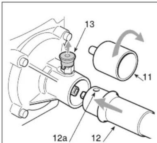
- Remove the protective cuffs (11) from both ends of the flexible drive tube (12), taking note that there are differences between them.
- Lift the pin (13), turning it so that it remains lifted and insert the end with the hole (12a) in the seat of the power unit, ensuring that the hole is turned upward.
- Release the pin (13), making sure it is lowered completely to lock the end of the tube (12a).
- Insert the end with the groove (12b) in the protruding hub of the front handgrip (14) and fasten it with the screw (15) ensuring it stays locked.
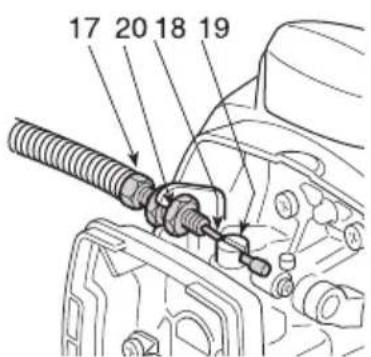
- Insert the register (17) of the throttle wire in the support slot and connect the wire (18) to the carburettor lever (19); then work the nuts (20) to tighten the wire and block the register on the support.
- Connect the two terminals of the cables (21) and (22) to the corresponding cables on the power unit.
1.2 FITTING THE GUARD ON THE CUTTING DEVICE (Fig. 5)
▲ WARNING! Each cutting device is provided with a specific guard. Never use guards other than those indicated for each cutting device.
WARNING! Year protective gloves and fit the blade guard.
- Remove the screw (1) from the guard (2).
- Insert the tab (3) in the guard seat (2) and fasten the guard with the screw (1).
1.3 FITTING AND REMOVING CUTTING DEVICES AND PREPARING GUARDS
WARNING! Use only original cut-
ting devices or ones homologated by the Manufacturer.
1.3.1 Selecting the cutting device
Choose the most suitable cutting device for the job to be done, according to these general indications:
- the 3-point blade is suitable for cutting brushwood and small shrubs up to 2cm in diameter;
- the 4-point blade is suitable for cutting tough grass over large surfaces;
- the cutting line head can eliminate tall grass and non-woody vegetation near fences, walls, foundations, pavements, around trees, etc. or completely clean a particular area of the garden;
- the saw blade (if permitted) allows small woody parts to be cut and small trees to be felled.
Every cutting device must be fitted with a specific guard, as indicated by the following directions.
IMPORTANT The cutting devices are fastened with a left-hand thread and therefore must be unscrewed clockwise and screwed on anticlockwise. Remove all elements that may have assembled, which will be used in various configurations, according to the cutting device used.
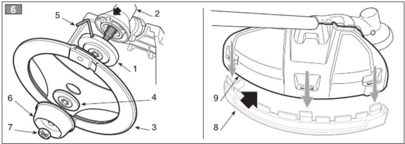
1.3.2 3 or 4-point blade "Tri-Arc" blade" (Fig. 6)
a) Assembly
- Fit the inner ring-nut (1) in the indicated direction, making sure that the inner ring-nut's grooves match perfectly with those of the angle transmission (2).
- Fit the blade (3) and the outer ring-nut (4), with the flat part toward the blade.
- Insert the supplied wrench (5) in the specific hole, then turn the blade (3) by hand and push the wrench (5) until it enters the hole of the angle transmission (2), blocking rotation.
- Fit the cup (6) fully tightening the nut (7) anticlockwise (25 Nm).
- Remove the wrench (5) to restore rotation.
b) Adjusting the guard
- Remove the additional guard (8 - if already fitted), unhooking hooks clicked into the guard (9).
c) Disassembly
- Insert the supplied wrench (5) in the specific hole, then turn the blade (3) by hand and push
the wrench (5) until it enters the hole of the angle transmission (2), blocking rotation.
- Unscrew the nut (7) clockwise and remove the cup (6).
- Pull out the outer ring-nut (4), then remove the blade (3) and the inner ring-nut.
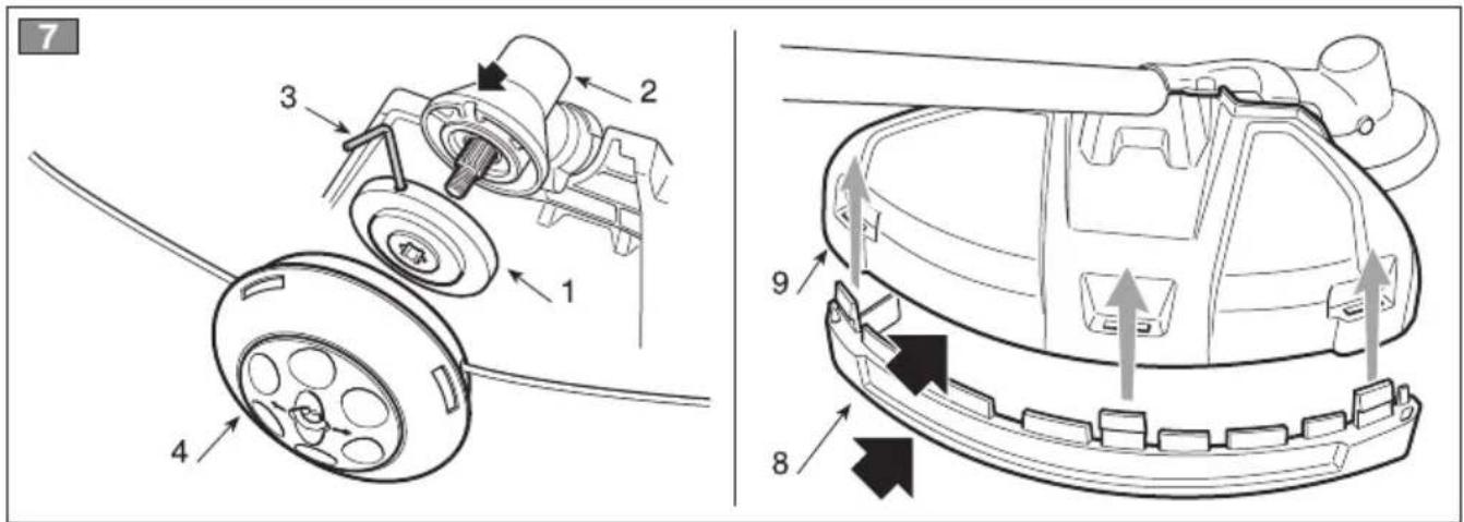
1.3.3 Cutting line head (Fig. 7)
a) Assembly
- Fit the inner ring-nut (1) in the indicated direction, making sure that the inner ring-nut's grooves match perfectly with those of the angle transmission (2).
- Insert the supplied wrench (3) in the specific hole of the inner ring-nut (1), then turn the ring-nut by hand and push the wrench (3) until it enters the hole of the angle transmission (2), blocking rotation.
- Fit the cutting line head (4) screwing it anticlockwise.
- Remove the wrench (3) to restore rotation.
b) Adjusting the guard
- Fit the additional guard (8), inserting the couplers into the respective seats in the guard (9) and pressing until a click is heard.
be eWARNING! When using the cutting line head, the additional guard, with line cutting knife, must always be fitted.
c) Disassembly
- Insert the supplied wrench (3) in the specific hole of the inner ring-nut, then turn the ring-nut by hand and push the wrench (3) until it enters the hole of the angle transmission (2), blocking rotation.
- Remove the cutting line head (4) unscrewing it clockwise.
1.3.4 Saw blade (if permitted) (Fig. 8)
a) Assembly
- Fit the inner ring-nut (1) in the indicated direction, making sure that the grooves match perfectly with those of the angle transmission (2).
- Fit the blade (3) and the outer ring-nut (4), with the flat part toward the blade.
- Insert the supplied wrench (5) in the specific hole, then turn the blade (3) by hand and push the wrench (5) until it enters the hole of the angle transmission (2), blocking rotation.
- Fit the cup (6) fully tightening the nut (7) anticlockwise (25 Nm).
- Remove the wrench (5) to restore rotation.
b) Adjusting the guard
- Remove the guards that may have been used
for other cutting devices and apply the specific guard for the saw blade.
WARNING! This guard must not be used for other cutting devices.
c) Disassembly
- Insert the supplied wrench (5) in the specific hole, then turn the blade (3) by hand and push the wrench (5) until it enters the hole of the angle transmission (2), blocking rotation.
- Unscrew the nut (7) clockwise and remove the cup (6).
- Pull out the outer ring-nut (4), then remove the blade (3) and the inner ring-nut.
2. PREPARING TO WORK
2.1 CHECKING THE MACHINE
Before starting work please:
- check that all the screws on the machine and the cutting device are tightly fastened;
- check that the cutting device is undamaged and that the 3 or 4-point metal blades (if fitted) are properly sharpened;
– check that the air filter is clean; - check that the guards are suited to the cutting device being used, properly fastened and efficient;
– check the handgrips are well fastened.
2.2 PREPARING THE FUEL MIXTURE
This machine is fitted with a two-stroke engine which requires a mixture of petrol and lubricating oil.
IMPORTANT Using petrol alone will damage the engine and is cause for invalidation of the warranty.
IMPORTANT Use only quality fuels and maintain high performance and guarantee the duration of the mechanical parts over time.
2.2.1 Petrol characteristics
Only use unleaded petrol with a fuel grade of at least 90 ON.
IMPORTANT Unleaded petrol tends to create deposits in the container if preserved for more than 2 months Always use fresh petrol!
2.2.2 Oil characteristics
Only use top quality synthetic oil specifically for two-stroke engines.
Your Dealer can provide you with oils which have been specifically developed for this type of engine, and which are capable of guaranteeing a high level of protection.
The use of these oils makes it possible to prepare a 2% mixture, consisting in 1 part oil to 50 parts petrol.
2.2.3 Preparation and preservation of the fuel mixture
DANGER! Petrol and the fuel mixture are highly inflammable!
- Keep the petrol and fuel mixture in homologated fuel containers, in a safe place, away from any flames or heat sources.
- Never leave the containers within the reach of children.
- Never smoke whilst preparing the mixture and avoid inhaling the petrol fumes.
To prepare the fuel mixture:
- Place about half the amount of petrol in a homologated tank.
- Add all the oil, according to the chart.
– Add the rest of the petrol. - Close the top and shake well.
IMPORTANT The fuel mixture tends to age. Do not prepare excessive amounts of the fuel mixture to avoid the formation of deposits.
IMPORTANT Keep the petrol and fuel mixtu containers separate and easily identifiable to avoid the mistake of using one in place of the other.
IMPORTANT Periodically clean the petrol and fuel mixture containers to remove any event deposits.
oils to
2.3 REFUELLING
DANGER! Never smoke whilst refuelling and avoid inhaling the petrol fumes.
WARNING! Carefully open the tank top as pressure could have formed inside.
Before refuelling:
- Shake the fuel mixture container well.
-
Place the machine on a flat stable surface, with the fuel tank cap facing upwards.
-
Clean the fuel tank cap and the surrounding area to avoid any dirt from entering the tank during refilling.
- Carefully open the fuel tank cap to allow the pressure inside to decrease gradually. Use a funnel to refill and avoid filling the tank to the brim.
WARNING! cap firmly.
Always close the fuel
⚠ WARNING! Immediately clean all traces of fuel which may have dripped on the machine or the ground and do not start the engine until the petrol fumes have dissipated.
3. USING THE MACHINE
3.1 STARTING THE MACHINE
WARNING! The machine must be started in an area at least 3 metres from where you refilled the fuel tank.
Before starting the engine:
- Place the machine firmly on the ground.
- Remove the guard from the blade (if used).
- Make sure the blade (if used) is not touching the ground or any other object.
3.1.1 Cold starting
WARNING! A "cold" start of the engine means starting it after at least 5 minutes from when it was switched off or after refuelling.
To start the machine (Fig. 9):
- Models SBC 627 K/KD - 635 K/KD 643 KD - 645 K/KD/KF - 653 KF:
Set the switch (1) to position «I».
Models SBC 653 K/KD:
Set the switch (1) to position «I».
Press the lock lever (3), activate the throttle (2) and holding them in this position, press the shutter (1a) button, then release the lever (3) and the throttle (2), so the button (1a) stays pressed.
-
Operate the choke, turning the lever (5) to the «B» position".
-
Press the primer device button (6) 3 or 4 times to prime the carburettor.
-
Hold the machine firmly on the ground with one hand on the power unit, in order not to lose control of the machine during startup (Fig. 10).
IMPORTANT To prevent distortions, the drive tube must not be used as a support for the hand or knee during startup.
- Pull the starter grip slowly for 10 - 15 cm until you feel some resistance, then tug it a few times until you hear the engine turn over.
IMPORTANT To avoid breaking the starter catartke, do not pull the whole length of it or let it slide along the edge of the cable guide hole. Release the starter grip gradually, to avoid letting it fly back uncontrollably.
- Pull the starter grip again until the engine starts as normal.
⚠ WARNING! Starting the engine with the choke engaged causes the cutting device to move, only stopping when the choke is disconnected.
- Models SBC 627 K/KD - 635 K/KD 643 KD - 645 K/KD/KF :
Briefly activate the throttle (2) to bring the engine down to minimum, with the lever (5) which will move automatically to the «A» position.
Models SBC 653 KF:
As soon as the engine is started, disengage the choke turning the lever (5) to the «A» position and briefly operate the throttle (2)
Models SBC 653 K/KD:
As soon as the engine is started, disengage the choke turning the lever (5) to the «A» position and briefly operate the throttle (2) to disengage the shutter (1a) and bring the engine down to minimum.
- Let the engine run idle for at least 1 minute before using the machine.
IMPORTANT If the starter grip is pulled repeatedly with the choke on, it may flood the engine and make starting difficult.
If you have flooded the engine, remove the spark plug and gently pull the starter grip to eliminate any excess fuel; then dry the spark plug electrodes and replace it on the engine.
3.1.2 Warm starting
When warm starting (immediately after stopping the engine), follow the procedure indicated above in points 1-4-5-6.
3.2 ADJUSTING THE SPEED OF THE CUTTING DEVICE (Fig. 9)
Cutting device speed is regulated by the throttle trigger (2), located on the rear handgrip (4) or the right handgrip (4) of the handlebar.
The throttle trigger only works if the lockout (3) is pressed at the same time.
The movement is transmitted from the engine to the transmission shaft by a centrifugal mass clutch that prevents the shaft from moving when the engine is running at minimum speed.
WARNING! The cutting device must not move when the engine is running idle. If the cutting device moves when the engine is running idle, contact your dealer to correctly regulate the engine.
The correct running speed will be achieved by pressing the throttle trigger (2) as far as possible.
IMPORTANT Avoid using the engine at full power for the first 6-8 working hours.
3.3 STOPPING THE MACHINE (Fig. 9)
To stop the machine:
- Release the throttle trigger (2) and allow the engine to run idle for a few seconds.
- Set the switch (1) to position «O».
WARNING! When you have reduced speed to a minimum, it will take onds for the cutting device to stop.
4. OPERATING MODES AND WORK TECHNIQUES
To respect people and the environment:
– Try not to cause any disturbance.
- Scrupulously comply with local regulations and provisions for the disposal of waste materials after cutting.
- Scrupulously comply with local regulations and provisions for the disposal of oils, petrol, damaged parts or any elements which have a strong impact on the environment.
WARNING! Prolonged exposure to vibrations can cause injuries and neural disorders (also called "Raynaud's syndrome" or "white hand"), especially to people suffering from circulation disorders. The symptoms can regard the hands, wrists and fingers and are shown through loss of sensi-
tivity, torpor, itching, pain and discolouring of or structural changes to the skin. TI effects can be worsened by low ambient temperatures and/or by gripping the handgrips excessively tightly. If the symptoms occur, the length of time the machine is used must be reduced and a doctor consulted.
DANGER! This machine's starter unit generates an average sized electromagnetic field, but it is not however possible to exclude the possibility of interference on any active or passive medical devices that operators may be wearing; this could be risky for their health conditions. All those using medical devices should always consult their GP, or the device manufacturer, before using this machine.
WARNING! Always wear suitable clothing when using the machine. Your dealer can provide you with all the information on the most suitable accident-prevention devices to guarantee your safety.
4.1 USING THE HARNESS (Fig. 11)
WARNING! The machine must always be used connected to the harness worn correctly. Frequently check the efficiency of the quick release in order to free the mach quickly from the belts in the event of danger.
a The names must be put on before connecting the machine to the special coupling and the belts must be adjusted to suit the operator's height and stature.
If the machine has more than one coupling hole, use the most favourable point for keeping the machine balanced when working.
Always use a harness that is suited to the weight of the machine:
– for machines weighing less than 7.5 kg, single or double belt models can be used;
- only the double belt model must be used for machines weighing more than 7.5 kg.
4.1.1 Single belt model
The belt (1) must go over the left shoulder towards the right hip.
4.1.2 Double belt model
The belt (2) must be worn with:
- the machine's support and snap-hook coupling on the right side;
– the release in front (2.2); - the belts cross-over on the operator's back (2.3);
– the buckle properly fastened on the left side (2.4).
The belts must be tensioned so that the load is evenly distributed on the shoulders.
⚠ WARNING! When working, the machine
must always be firmly held in both hands, keeping the power unit on the right body and the cutting group below the line of the belt.
Before tackling a mowing job for the first time it is advisable to gain the necessary familiarity with the machine and the most suitable cutting techniques, finding out how to wear the harnesses correctly, firmly gripping the machine and making the movements required by the job.
Choose the most suitable cutting device for the job to be done and prepare the machine as indicated in chapter 2).
4.3 WORK TECHNIQUES
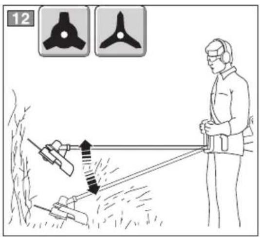
4.3.1 3 or 4-point blade - "Tri-Arc" blade" (Fig. 12)
Start cutting above the undergrowth and then move down with the scything blade so as to cut the brush into small pieces.
4.3.2 4-point blade (Fig. 13)
Proceed using the machine as a traditional scythe, with a circular movement of about 60-90°, thus moving outside the undergrowth, and so on.
4.3.3 Cutting line head
⚠ WARNING! Use ONLY nylon lines. The use of metal lines, plasticised metal lines and/or lines not suitable for the head can cause serious injuries and wounds.
During use it is advisable to stop the engine periodically and remove the weeds wound round the machine, so as to prevent the drive tube from overheating due to the grass caught under the guard.
Remove the caught-up grass with a screwdriver
to allow the rod to be properly cooled.
⚠ WARNING! Do not use the machine for sweeping, tilting the cutting line head. The power of the engine could throw objects and small stones 15 metres or more, causing damage or injuries to people.
a) Cutting in motion (Scything) (Fig. 14)
Proceed at a regular pace, with a circular motion similar to a traditional scythe, without tilting the cutting line head during the operation.
First try cutting at the right height in a small area, sof asthe then achieve a uniform cutting height keeping the cutting line head at a constant distance from the ground.
For heavier cutting it can be useful to tilt the cutting line head by about 30° .
⚠ WARNING! Do not work in this way there is the possibility of causing objects to be thrown, which could harm people, animals or cause damage.
b) Precision cutting (Trimming)
Keep the machine slightly tilted so that the lower part of the cutting line head does not touch the ground and the cutting line is at the required point, always keeping the cutting device at a distance from the operator.
c) Cutting near fences/foundations (Fig. 15)
Slowly move the cutting line head near fences, posts, rocks, walls, etc. without hitting them hard.
If the line strikes a solid object it could break or become worn; if it gets tangled in a fence it could break abruptly.
In any case, cutting around pavements, foundations, walls, etc. can cause greater wear than normal to the line.
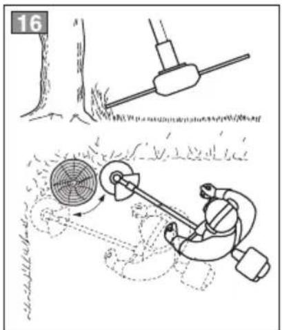
d) Cutting round trees (Fig. 16)
Walk round the tree from left to right, approaching the trunks slowly so as not to strike the tree with the line and keeping the cutting line head tilted forward slightly.
Remember that the nylon line could lop off or damage small shrubs and that the impact of the nylon line against the trunk of bushes or trees with soft bark could seriously damage the plant.
e) Adjusting line length when working (Fig. 17)
This machine is fitted with a “Tap & Go” head. To release more line, tap the cutting line head against the ground with the engine at top speed: the line will be released automatically and the knife will cut off the excess length.
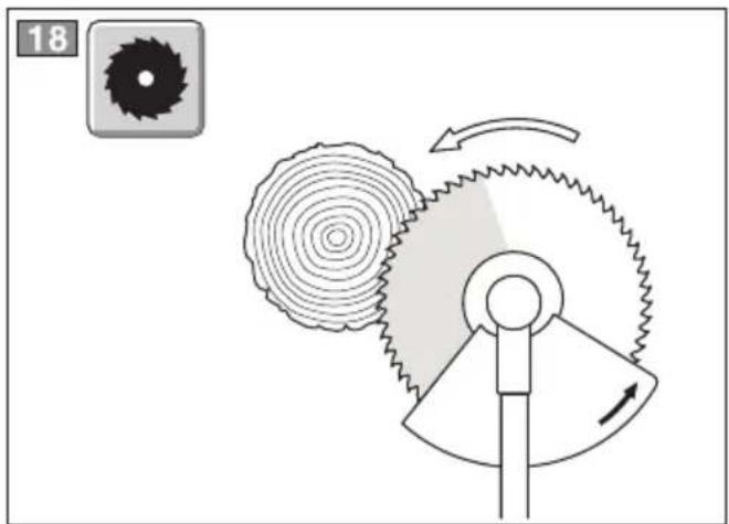
4.3.4 Saw blade (if permitted) (Fig. 18)
⚠ WARNING! When using the saw blade, where permitted, the specific guard must always be fitted. The blade must always be well sharpened to reduce the risk of kickback.
⚠ WARNING! When felling small trees, estimate the direction in which the cut tree will fall, also taking the wind direction into con-5.3 STARTING UNIT sideration.
To get a good result when felling small trees, the cut must be made with a rapid movement towards the branch or trunk to be cut, with the engine at maximum revs.
Do not use the right-hand area of the blade because there is a high risk of kickback or the blade seizing up, due to the direction of rotation.
4.4 WHEN WORK IS FINISHED
When you have finished your work:
- Stop the machine as indicated previously (see 3.3).
- Wait for the cutting device to stop and then mount the blade guard.
5. ROUTINE MAINTENANCE
Correct maintenance is essential to maintain the original efficiency and safety of the machine over time.
WARNING! During maintenance operations:
- Remove the spark plug cap.
- Wait until the engine is sufficiently cold.
- Use protective gloves when handling the blades.
- Keep the blade protection device cept when intervening directly on the blade.
- Never dispose of oils, fuel or other polluting materials in unauthorised places.
5.1 STORAGE
At the end of each working session, carefully clean the machine of dust and debris, and make
sure that there are no damaged parts, replacing any faulty parts. The machine must be stored in a dry place away from the elements and with the cover correctly fitted.
5.2 CLEANING THE ENGINE AND THE SILENCER
To reduce fire risks, periodically clean the cylinder fins with compressed air and clear the silencer area to get rid of sawdust, branches, leaves or other debris.
.5.3 STARTING UNIT
To avoid overheating and damage to the engine, always keep the cooling air vents clean and free of sawdust and debris.
If you notice signs of wear on the starter cable, contact your Dealer for a replacement.
5.4 NUTS AND SCREWS
Periodically check that all the nuts and screws are securely tightened and the handgrips are tightly fastened.
5.5 CLEANING THE AIR FILTER (Fig. 19)
IMPORTANT Cleaning the air filter is essential to guarantee the efficiency and duration of the machine. Do not work with a damaged filter or without a filter, as this could permanently damage the engine.
It must be cleaned after every 15 working hours.
Clean the filter as follows:
- Loosen the knob (3), remove the cover (1) and the filter element (2).
- Wash the filter element (2) with soap and water. Do not use petrol or other solvents.
– Leave the filter to dry in the open air. - Fit the filter element (2) and the cover (1) back on, tightening the knob (3) again.
on, ex-
5.6 CHECKING THE SPARK PLUG (Fig. 20)
Periodically remove and clean the spark plug using a metal brush to get rid of any deposits.
Check and reset the correct distance between the electrodes.
Replace the spark plug and fasten it firmly using the supplied wrench.
The spark plug must be replaced with one with the same characteristics whenever the electrodes have burnt or the insulation has worn, and in any case every 100 working hours.
5.7 LUBRICATION
IMPORTANT To preserve drive parts, we recommend greasing the angle gear and flexible shaft every 15 hours of use.
ANGLE TRANSMISSION (Fig. 21a)
Lubricate with lithium-based grease.
Remove the screw (1) and put in the grease, turning the shaft manually until grease emerges, then replace the screw (1).
FLEXIBLE SHAFT (Fig. 21b)
Models SBC 645 KF - 653 KF:
Lubricate with lithium-based grease.
Unhook the hose (12) from the motor side, extract the flexible shaft (12 c) and apply grease rotating the shaft manually until the grease is distributed over the entire surface; then reassemble
⚠ WARNING! Use protective gloves. If sharpening is done without removing the blade, disconnect the spark plug cap.
Sharpening must be done taking account of the type of blade and cutting edges, using a flat file and working all the points equally.
The references for correct sharpening are given in Fig. 22:
A = Incorrect sharpening
B = Sharpening limits
C = Incorrect and unequal angles
IMPORTANT It is important to retain the correct balance after sharpening. For safety reasons, sharpening and balancing should be done
Specialised Centre with suitable skills and equipment for the job; without risking any damage the blade which would make it unsafe when used.
3 or 4-point blades can be used on both sides. When one side of the points is worn, the blade can be turned and the other side used.
WARNING! The blade must never be repaired, but must be replaced as soon as signs of breaking are noted or the sharpening limit is exceeded.
5.8.2 Sharpening the 3 or 4-point blade
Blades bearing the code indicated on the chart on page 3 should be used on this machine.
Given product evolution, the above mentioned blades may be replaced in time with others having similar interchangeable and operating safety features.
5.9 HEAD LINE REPLACEMENT
5.9.1 Cutting line head type "I" (Fig. 23)
- Remove the remaining line pulling it out of the centre of the starter grip (1). If it is broken off inside, press the point indicated «PUSH», turn the head cover (2) anticlockwise and remove the line remaining inside. Close the head again, aligning the reference notch (3) and turn the cover (2) clockwise.
WARNING! Make sure the head is properly closed along the entire perimeter to prevent it from opening during work, with risk of damage or injuries.
- Cut the line to the indicated length.
- Turn the starter grip (1) clockwise until one of the arrows is aligned with one of the two exit holes (4) of the line.
- Insert the two ends of the line in the centre of the starter grip (1), making the line exit the two holes (4) in equal parts.
- Turn the grip (1) clockwise to wind the line, letting about 120 mm exit from both holes.
5.9.2 Cutting line head type "II" (Fig. 24)
– Follow the sequence indicated in the figure.
5.10 SHARPENING THE LINE CUTTING ns, by a KNIFE (Fig. 25)
- Remove the line cutting knife (1) from the page to guard (2) by unscrewing the screws (3).
- Fix the line cutting knife in a vice and sharpen it using a flat file, being careful to retain the original cutting angle.
– Refit the knife on the guard.
5.11 LONG PERIODS OF DISUSE
IMPORTANT If you are not going to use the machine for a period of more than 2-3 months, we recommend you do a few things before putting it away. This will make it easier when you want to use the machine again and will also prevent permanent damage to the engine.
Before putting the machine away:
- Empty the fuel tank.
- Start the engine and run it idle until it comes to a halt, so that it uses up all the fuel that is left in the carburettor.
- Wait for the engine to cool down before storing the machine.
When you wish to start using the machine again, prepare it as indicated in chapter "2. Preparing to work".
6. EXTRAORDINARY MAINTENANCE
This work must be done exclusively by your Dealer.
All and any operations performed in unauthorised centres or by unqualified persons will totally invalidate the warranty.
6.1 TUNING MINIMUM SPEED
⚠ WARNING! If the cutting device moves when the engine is running idle, contact your Dealer to correctly regulate the engine.
6.2 CARBURETTOR ADJUSTMENTS
The carburettor is tuned by the manufacturer to achieve maximum performance in all situations, with a minimum emission of toxic gas in compliance with the regulations in force.
In the case of poor performance contact your Dealer for a check of the carburation and engine.
The blade must never be repaired, but must be replaced as soon as signs of breaking are noted or the sharpening limit is exceeded.
- DIAGNOSTICS
| What to do when ... | |
| Source of problem Corrective action | |
| 1. The engine will not start or will not keep running | |
| Incorrect starting procedure | Follow the instructions (see chapter 3) |
| Dirty spark plug or incorrect distance between the electrodes | Check the spark plug (see chapter 5) |
| Air filter clogged Clean and/or replace the filter (see chapter 5) | |
| Carburation problems Contact your Dealer | |
| 2. The engine starts but is lacking in power | |
| Air filter clogged | Clean and/or replace the filter (see chapter 5) |
| Carburation problems | Contact your Dealer |
| 3. The engine runs irregularly and lacks in power when revved | |
| Dirty spark plug or incorrect distance between the electrodes | Check the spark plug (see chapter 5) |
| Carburation problems | Contact your Dealer |
| 4. The engine makes too much smoke | |
| Incorrect composition of the fuel mixture | Prepare the fuel mixture according to the instructions (see chapter 2) |
| Carburation problems | Contact your Dealer |
| 5. The cutting device must not move when the engine is running idle | |
| Incorrect carburation regulation | Contact your Dealer |
⚠ WARNING! For safety reasons, sharpening and balancing should be done by a Specialised Centre with suitable skills and equipment for the job; without risking any damage to the blade which would make it unsafe when used.
WARNING! The saw blade is not reversible, thus it must only be used from one side.
• OND: 2000/14/EC, ANNEX V D. Lgs. 262/2002, ANNEX V (Italy)
• EMCD: 2004/108/EC
• OND: 2000/14/EC, ANNEX V
D. Lgs. 262/2002, ANNEX V (Italy)
• EMCD: 2004/108/EC
Model: ....
Type:
-s/n -Art.N

CE
GGP ITALY SPA
Via del Lavoro, 6
I-31033 Castelfranco Veneto (TV) ITALY

GLOBAL GARDEN PRODUCTS
© by GGP ITALY spa
- Soggetto a modifiche senza preavviso • Подлежи на промени без предупреждение • Moguće su promjene bez najave • Možnost změn bez předešlého upozornění • Ret til ændringer forbeholdes • Kann ohne Vorankündigung geändert werden • Упóкеятαι σε αλλαγές χωρίς προειδοποίηση • Subject to modifications without notice • Sujeto a modificaciones sin previo aviso • Võimalikud muudatused ilma ette teatamata • Voidaan tehdä muutoksia ilman ennakkoilmoitusta • Sujet à des modifications sans aucun préavis • Podložno promjenama bez prethodne obavijesti • Előzetes értesítés nélkül módosítható • Objekto pakeitimai be perspėjimo • Var tikt mainīts bez iepriekšēja brīdinājuma • Подлежи на промени без претходно известување • Kan zonder kennisgeving wijzigingen ondergaan • Kan endres uten forvarsel • Poddawany modyfikacjom bez awizowania • Sujeito a alterações sem aviso prévio • Poate fi modificat, fără preaviz • Может быть изменено без преомления • Možnosť zmien bez predošlého upozornenia • Lahko pride do sprememb brez predhodnega obvestila • Podložno izmenama bez upozorenja • Kan utsättas för modifieringar utan att detta meddelas • Önceden haber verilmeksizin değiştirilebilir




- TABLE OF CONTENTS
- HOW TO READ THE MANUAL
- NOTE OR
- GETTING TO KNOW THE MACHINE
- DESCRIPTION OF THE MACHINE AND ITS RANGE OF USE
- INTENDED USE
- IMPROPER USE
- IDENTIFICATION LABEL AND MACHINE COMPONENTS
- DESCRIPTION OF EXPLANATORY SYMBOLS (WHERE APPLICABLE)
- SAFETY REQUIREMENTS
- TECHNICAL DATA AND ACCESSORIES
- SAFETY REGULATIONS TO BE OBSERVED SCRUPULOUSLY
- TRAINING
- PRELIMINARY OPERATIONS
- DURING USE
- TRANSPORTATION AND HANDLING
- OPERATING INSTRUCTIONS
- MACHINE ASSEMBLY
- 1.1 COMPLETING THE MACHINE
- 1.1A. MODELS SBC 627 K - 635 K - 645 K 653 K (FIG. 1)
- 1.1B MODELS SBC 627 KD - 635 KD - 643 KD (FIG. 2)
- 1.1C MODELS SBC 645 KD - 653 KD (FIG. 3)
- 1.1D MODELS SBC 645 KF - 653 KF (FIG. 4)
- 1.2 FITTING THE GUARD ON THE CUTTING DEVICE (FIG. 5)
- WARNING! YEAR PROTECTIVE GLOVES AND FIT THE BLADE GUARD
- 1.3 FITTING AND REMOVING CUTTING DEVICES AND PREPARING GUARDS
- 1.3.1 SELECTING THE CUTTING DEVICE
- 1.3.2 3 OR 4-POINT BLADE "TRI-ARC" BLADE" (FIG. 6)
- ASSEMBLY
- ADJUSTING THE GUARD
- DISASSEMBLY
- 1.3.3 CUTTING LINE HEAD (FIG. 7)
- 1.3.4 SAW BLADE (IF PERMITTED) (FIG. 8)
- WARNING! THIS GUARD MUST NOT BE USED FOR OTHER CUTTING DEVICES
- PREPARING TO WORK
- 2.1 CHECKING THE MACHINE
- 2.2 PREPARING THE FUEL MIXTURE
- 2.2.1 PETROL CHARACTERISTICS
- 2.2.2 OIL CHARACTERISTICS
- 2.2.3 PREPARATION AND PRESERVATION OF THE FUEL MIXTURE
- DANGER! PETROL AND THE FUEL MIXTURE ARE HIGHLY INFLAMMABLE
- 2.3 REFUELLING
- DANGER! NEVER SMOKE WHILST REFUELLING AND AVOID INHALING THE PETROL FUMES
- WARNING! CAREFULLY OPEN THE TANK TOP AS PRESSURE COULD HAVE FORMED INSIDE
- WARNING! CAP FIRMLY
- USING THE MACHINE
- 3.1 STARTING THE MACHINE
- 3.1.1 COLD STARTING
- 3.1.2 WARM STARTING
- 3.3 STOPPING THE MACHINE (FIG. 9)
- OPERATING MODES AND WORK TECHNIQUES
- 4.1 USING THE HARNESS (FIG. 11)
- 4.1.1 SINGLE BELT MODEL
- 4.1.2 DOUBLE BELT MODEL
- ⚠ WARNING! WHEN WORKING, THE MACHINE
- 4.3 WORK TECHNIQUES
- 4.3.1 3 OR 4-POINT BLADE - "TRI-ARC" BLADE" (FIG. 12)
- 4.3.2 4-POINT BLADE (FIG. 13)
- 4.3.3 CUTTING LINE HEAD
- ⚠ WARNING! USE ONLY NYLON LINES. THE USE OF METAL LINES, PLASTICISED METAL LINES AND/OR LINES NOT SUITABLE FOR THE HEAD CAN CAUSE SERIOUS INJURIES AND WOUNDS
- ⚠ WARNING! DO NOT USE THE MACHINE FOR SWEEPING, TILTING THE CUTTING LINE HEAD. THE POWER OF THE ENGINE COULD THROW OBJECTS AND SMALL STONES 15 METRES OR MORE, CAUSING DAMAGE OR INJURIES TO PEOPLE
- CUTTING IN MOTION (SCYTHING) (FIG. 14)
- ⚠ WARNING! DO NOT WORK IN THIS WAY THERE IS THE POSSIBILITY OF CAUSING OBJECTS TO BE THROWN, WHICH COULD HARM PEOPLE, ANIMALS OR CAUSE DAMAGE
- PRECISION CUTTING (TRIMMING)
- CUTTING NEAR FENCES/FOUNDATIONS (FIG. 15)
- CUTTING ROUND TREES (FIG. 16)
- ADJUSTING LINE LENGTH WHEN WORKING (FIG. 17)
- 4.3.4 SAW BLADE (IF PERMITTED) (FIG. 18)
- 4.4 WHEN WORK IS FINISHED
- ROUTINE MAINTENANCE
- 5.1 STORAGE
- 5.2 CLEANING THE ENGINE AND THE SILENCER
- 5.3 STARTING UNIT
- 5.4 NUTS AND SCREWS
- 5.5 CLEANING THE AIR FILTER (FIG. 19)
- 5.6 CHECKING THE SPARK PLUG (FIG. 20)
- 5.7 LUBRICATION
- ANGLE TRANSMISSION (FIG. 21A)
- FLEXIBLE SHAFT (FIG. 21B)
- MODELS SBC 645 KF - 653 KF
- ⚠ WARNING! USE PROTECTIVE GLOVES. IF SHARPENING IS DONE WITHOUT REMOVING THE BLADE, DISCONNECT THE SPARK PLUG CAP
- 5.8.2 SHARPENING THE 3 OR 4-POINT BLADE
- 5.9 HEAD LINE REPLACEMENT
- 5.9.1 CUTTING LINE HEAD TYPE "I" (FIG. 23)
- WARNING! MAKE SURE THE HEAD IS PROPERLY CLOSED ALONG THE ENTIRE PERIMETER TO PREVENT IT FROM OPENING DURING WORK, WITH RISK OF DAMAGE OR INJURIES
- 5.9.2 CUTTING LINE HEAD TYPE "II" (FIG. 24)
- 5.10 SHARPENING THE LINE CUTTING NS, BY A KNIFE (FIG. 25)
- 5.11 LONG PERIODS OF DISUSE
- EXTRAORDINARY MAINTENANCE
- 6.1 TUNING MINIMUM SPEED
- 6.2 CARBURETTOR ADJUSTMENTS
- GGP ITALY SPA
Brand : STIGA
Model : SBC 635 KD
Category : Lawn mower