
FLASH METER VI - Exposure and light measurement MINOLTA - Free user manual and instructions
Find the device manual for free FLASH METER VI MINOLTA in PDF.

| Product type | Handheld digital flash meter |
| Brand | Minolta |
| Model | Flash Meter VI |
| Category | Exposure and light measurement |
| Dimensions | Approximately 135 x 65 x 30 mm |
| Weight | Approximately 180 g (without battery) |
| Power supply | 2 AA alkaline batteries (LR6) or 1 6F22 9V battery |
| Main functions | Ambient light measurement (incident/reflected), wireless flash measurement (cable or wireless), flash duration measurement, value memory, digital display with backlight |
| Ambient light measurement range | 0 to 200,000 lux (ISO 100) |
| Flash measurement range | f/1.0 to f/45, sync speed from 1/1000 to 1/60 s |
| Protection rating | Not waterproof, dry indoor use recommended |
| Connectors | PC sync socket, 1/4 inch tripod mount |
| Included accessories | Protective case, strap, eyecup cover, test battery |
| Maintenance and cleaning | Wipe with a soft dry cloth; do not use solvents; remove batteries when not in use for extended periods |
| Safety | Do not expose to moisture or shocks; use only recommended batteries; observe polarity |
| Spare parts and repairability | Parts not available from manufacturer; repair by authorized service only |
| General information | Manual available for free download in PDF format; flash compatibility via cable or wireless trigger |
Frequently Asked Questions - FLASH METER VI MINOLTA
User questions about FLASH METER VI MINOLTA
0 question about this device. Answer the ones you know or ask your own.
Ask a new question about this device
Download the instructions for your Exposure and light measurement in PDF format for free! Find your manual FLASH METER VI - MINOLTA and take your electronic device back in hand. On this page are published all the documents necessary for the use of your device. FLASH METER VI by MINOLTA.
USER MANUAL FLASH METER VI MINOLTA
Thank you for purchasing the MINOLTA FLASH METER VI.
The Minolta Flash Meter VI has the following features:
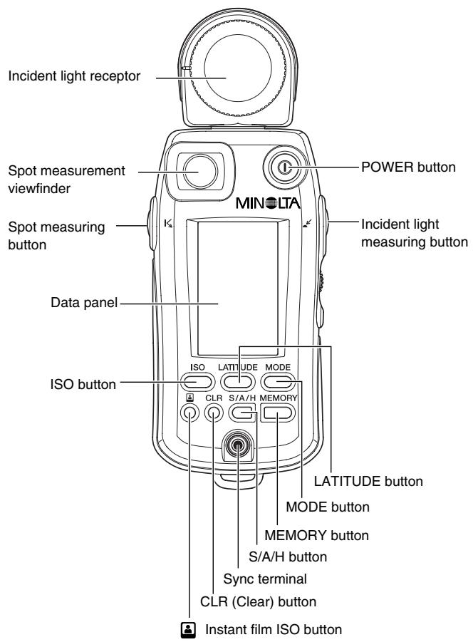
- The integrated exposure meter combines incident light measurement and spot (reflected light) measurement in a single unit.
- For spot measurement, the Flash Meter VI uses a parallax-free optical system. This eliminates the displacement of the measurement area that varies with the distance from the subject.
- With the latitude display function, the Flash Meter VI can simultaneously display the results of both incident light measurement and spot light measurement. It provides a clear and simple graphical decision process for determining the exposure suited to the nature of the photograph.
- With the analyze scale, you can determine the proportion of flash light and ambient light in a single flash light measurement.
- The Flash Meter VI provides a memory function capable of storing up to 10 measured values; an averaging function that calculates an average exposure from stored measurement data; and a brightness difference function that displays deviation from the standard exposure.
- For spot measurement, both shadow-based and highlight-based exposure calculation functions are provided.
- The Flash Meter VI provides a "custom setting (Alt) mode" that allows you to customize the meter according to your preference. This feature includes an exposure correction value setting function and a shutter speed increment-setting function.
- Measurement results are shown on both the analog and digital displays on the meter's data panel. The clear and legible display eliminates reading errors.
- The results of spot measurements are shown on the digital display in the viewfinder and on the external data panel. The viewfinder features a dioptic adjustment mechanism.
- In addition to displaying a conventional 10-level intermediate f-number display, the Flash Meter VI provides an f-number direct reading display. This enables the measured value to be applied to any camera with an f-number direct reading display, eliminating the need for f-number conversion.
Safety-related Icons
The following icons are used in this manual to alert you to important information for preventing accidents due to improper handling of equipment.

This denotes a safety-related caution. Read the caution carefully to ensure safe use of the product.

This denotes actions to be strictly avoided.
Make sure to avoid these actions.

This denotes actions to be avoided.
Do not attempt to disassemble the product.
SafetyWarnings and Cautions
To ensure proper use of the instrument, take special care to observe the following handling instructions when using this instrument. Read this instruction manual carefully and keep it securely in a place where you can refer to it readily.

WARNING
indicates a danger that improper use of the instrument will lead to the death or serious injury of the user.

Do not use the instrument in a place where inflammable or combustible vapors (e.g. gasoline) are present. Otherwise there is a risk of causing a fire.

Do not throw batteries into fire. Do not recharge (non-rechargeable batteries), short circuit, heat or disassemble batteries. Otherwise, there is a risk of causing fire or injury due to an explosion or fluid leakage.

Never attempt to disassemble or modify the instrument yourself. Otherwise there is a risk of causing fire or electric shock.

Never attempt to look directly at the sun through the viewfinder of the meter. Doing so will damage your eyesight.

The instrument should not be operated if it is damaged, or smoke or odd smells occur. Doing so may result in a fire. In such situations turn off the power immediately, disconnect the AC adapter, and contact the nearest authorized service facility.

CAUTION
indicates a danger that improper use of the instrument will lead to injury to the user or to property damage.

Do not use any batteries other than those designated for use with the instrument. When fitting batteries, make sure to align them according to the polarity shown on the instrument (plus "+" and minus "-"). Otherwise there is a risk that the batteries may leak or become damaged, leading to fire, injury or pollution of the surrounding environment.

Do not walk around while looking into the viewfinder. Doing so may result in a fall or other accident.
STATEMENT OF FCC COMPLIANCE
This equipment has been tested and found to comply with the limits for a Class B digital device, pursuant to Part 15 of the FCC Rules. These limits are designed to provide reasonable protection against harmful interference in a residential installation. This equipment generates, uses and can radiate radio frequency energy and, if not installed and used in accordance with the instructions, may cause harmful interference to radio communications. However, there is no guarantee that interference will not occur in a particular installation. If this equipment does cause harmful interference to radio or television reception, which can be determined by turning the equipment off and on, the user is encouraged to try to correct the interference by one or more of the following measures:
- Reorient or relocate the receiving antenna.
- Increase the separation between the equipment and receiver.
- Connect the equipment into an outlet on a circuit different from that to which the receiver is connected.
- Consult the dealer or an experienced radio/TV technician for help.
This Class B digital apparatus complies with Canadian ICES-003.
Table of Contents
Names of Parts and Displays 2
Data panel displays 4
Viewfinder display 8
Preparations 9
- Battery 9
1.Preparing 9
2.Inserting 9
3. Checking 10
-
Setting film speed 12
-
Setting instant film speed for test shooting 13
Selecting a measuring method suitable for the light-receiving method 14
-
Incident light measurement 14
2.Spot measurement 15 -
Difference between incident-light and Spot (reflected-light) readings 16
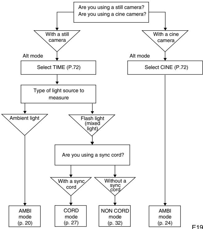
Basic Operation 19
Select a measuring method 19
Measuring ambient light 20
1.With a still camera 20
2.Withacine camera 24
Measuring flash light 27
1.Withasyncord 27
2. Without a sync cord (Incident light measurement) 32
* Light Ratio Analyze function 36
Special Functions 38
Latitude display function 38
Combining incident light measurement and spot measurement 40
Memory function 42
S/A/H (Shadow/Average/Highlight) calculations 45
Brightness difference function 52
Measuring lighting ratio using the Flat Diffuser 58
* Using the Flash Meter VI as a simplified illuminance meter 63
* Using the Flash Meter VI as a simplified luminance meter 63
- Custom settings mode (Alt mode) 66
74
Care and Storage 75
1.Care 75
2.Storage 75
Handling Instructions 76
After Service 77
Specifications 78
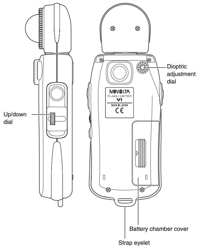
Names of Parts and Displays
Data panel displays
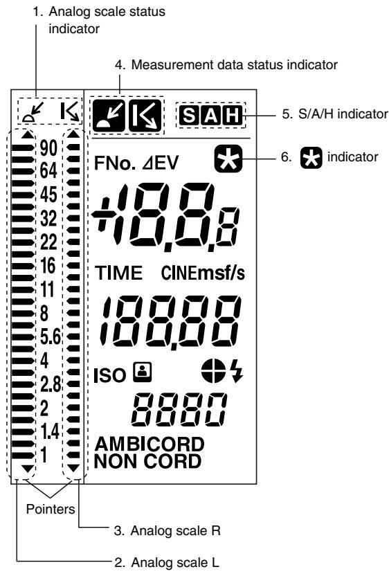
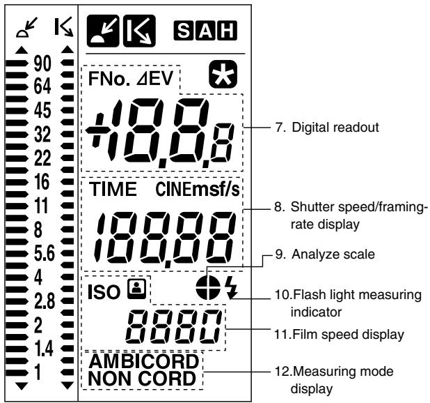
For the purpose of explanation, the diagram above shows all indicators that light up on the LCD.
1. Analog scale status indicator
The left (L) and right (R) analog scales are used for incident light measurement and spot measurement, respectively.
2. Analog scale L
The display of the pointers corresponds to measurement data and memory data for incident light measurement. It also corresponds to the
standard exposure or latitude for incident light measurement or spot measurement.
The small digit to the right of the two-digit reading (f-number) on the digital readout indicates a fractional value between stops. The value shown on the analog display is rounded down or up to the nearest 0.5 stops. (Values of 0.2 or lower are rounded down to 0; those of 0.3 to 0.7 are rounded to 0.5; and those of 0.8 or greater are rounded up to 1.)
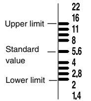
When a latitude range is indicated, all dots between the upper and lower limits are lit.
3. Analog scale R
The display of the pointers corresponds to measurement data and memory data for spot measurement.
The small digit to the right of the two-digit reading (f-number) on the digital readout indicates a fractional value between stops. The value shown on the analog display is rounded down or up to the nearest 0.5 stops. (Values of 0.2 or lower are rounded down to 0; those of 0.3 to 0.7 are rounded to 0.5; and those of 0.8 or greater are rounded up to 1.)
4. Measurement data status indicator
When a value measured with incident light measurement is displayed, the indicator appears. When a value measured with spot measurement is displayed, the indicator appears.
5. S/A/H indicator
Holding down the S/A/H button while a measured value is displayed lights the S, A or H indicator corresponding to the currently selected SAH mode.
6. indicator
This indicator turns on when the LATITUDE button is pressed.
For the purpose of explanation, the diagram above shows all indicators that light up on the LCD.
7. Digital readout
When the measurement data display unit is set to "FNo." or "FNo. direct reading," the f-number (FNo.) is displayed. When the display unit is set to "EV," the exposure value (EV) is displayed in 0.1-stop increments. For flash light measurement, only the FNo. display mode is available. Holding down the incident light measuring button or spot measuring button (which activates the brightness difference function) in latitude display mode causes EV (deviation from the standard exposure) to be displayed. When the measuring button is released, the standard exposure is displayed.
8. Shutter speed/framing-rate display
Displays the shutter speed or frame rate specified with the Up/down dial. When shutter speed is between 0.6 to 50 sec, s is displayed; between 1 min. and 30 min., m is displayed.
Setting range: Shutter speed: 30 min. to 1/16000 sec. (1, 1/2, 1/3 stops)
Framing-rate: 8, 12, 16, 18, 24, 25, 30, 32, 64,128 f/s
9. Analyze scale
Displays the proportion of flash light in the total exposure value obtained from flash light measurement. For more information on the Light Ratio Analyze function, see p. 36.
10. Flash light measuring indicator
This indicator appears together with the analyze scale in CORD and NON CORD mode.
11. Film speed display
Displays the film speed setting.
Holding down the instant film ISO button displays the indicator.
Setting range: ISO 3 to ISO 8000
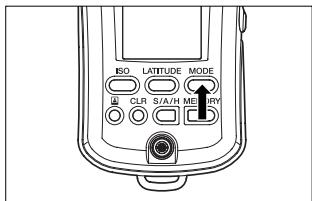
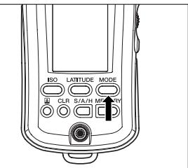
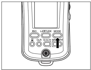
12. Measuring mode display
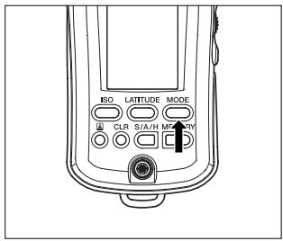
Displays one of the three measurement modes (AMBI, CORD or NON CORD) according to the setting of the MODE button.
Repeatedly pressing the MODE button cycles the measurement modes in the following sequence: AMBI CORD NONCORD AMBI
Viewfinder display
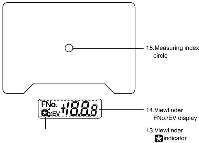
For the purpose of explanation, the above figure shows all available indicators on the display.
13.Viewfinder indicator
Same as the indicator on the external data panel.
14. Viewfinder FNo./EV display
Displays an f-number (FNo.) or exposure value (EV) during spot measurement.
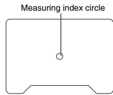
15. Measuring index circle
The circle's internal area indicates the measuring area for spot measurement.
Preparations
Battery
WARNING
Do not throw batteries into fire. Do not recharge (non-rechargeable batteries), short circuit, heat or disassemble batteries. Otherwise, there is a risk of causing fire or injury due to an explosion or fluid leakage.
CAUTION
Do not use any batteries other than those designated for use with the instrument. When fitting batteries, make sure to align them according to the polarity shown on the instrument (plus "+" and minus "-"). Otherwise there is a risk that the batteries may leak or become damaged, leading to fire, injury or pollution of the surrounding environment.
1. Preparing
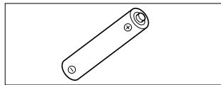
The instrument uses a single alkaline dry cell (LR-6/1.5 V).
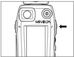
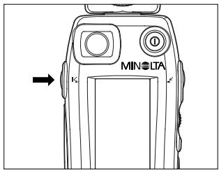
2. Inserting
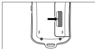
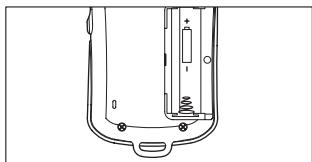
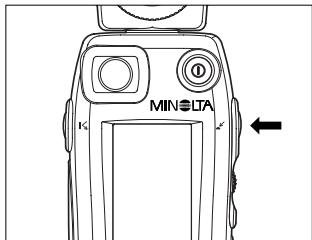
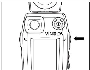
1 Remove the battery chamber cover by sliding it lightly in the direction of the arrow.
2 Insert the battery with the plus (+) and minus (-) ends oriented according to the diagram in the battery chamber.
- The meter will not work if the battery is inserted in the wrong direction.
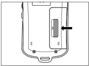
3 Replace the battery chamber cover.
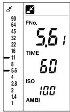
3. Checking
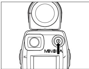
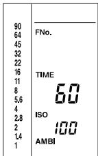
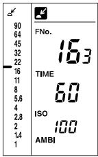
The instrument automatically checks the battery when power is on.
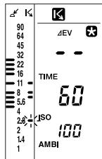
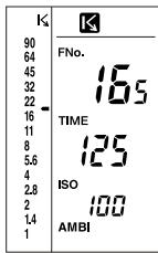
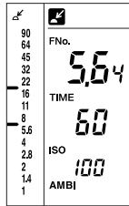
After a new battery is installed, the display appears as shown below after the power is turned on.
| 90 | |
| 64 | FNo. |
| 45 | |
| 32 | |
| 22 | |
| 16 | |
| 11 | TIME |
| 8 | ISO |
| 5.6 | |
| 4 | |
| 2.8 | ISO |
| 2 | |
| 14 | AMBI |
| 1 |
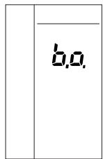
If you turn on the meter when the battery power is running low, "b.c." will appear on the display for approx. 0.5 sec. before the normal display appears.
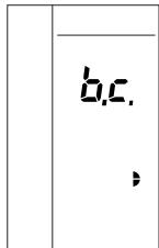
If you turn the power on when there is not enough battery power to take measurements, or if the battery runs low during measurement, a blinking "b.o." will display for approx. 1 min. and then the display will switch off. If this happens, replace the battery with a new one.
- When disposing of used batteries, observe local waste disposal regulations.
The Flash Meter VI can be operated continuously for about 30 hours with a fresh alkaline dry cell. - The Flash Meter VI has a power-saving function that automatically turns off the power after about 10 minutes of inactivity. To restart measuring operation after the display has been turned off, press the POWER button. (Pressing the POWER button restores the meter to the condition it was in before the power was turned off. The settings for film speed, shutter speed, measuring mode and display unit, as well as the existing measurement data and memory data, are all retained in memory.)
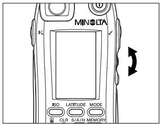
Setting film speed
Specify a film speed with the Up/down dial while holding down the ISO button.
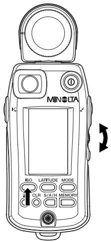
- Turning the control upward increases the film speed in increments of 1/3-stop. The maximum film speed is ISO 8000.
- Turning the control downward lowers the film speed in decrements of 1/3-stop. The minimum film speed is ISO 3.
- Be sure to set film speed to the correct setting, since all measurement results are based on the set value.
- If you change the film speed after you take a measurement, the reading will be recalculated and displayed accordingly.
Setting instant film speed for test shooting
If the film speed setting used for the final shooting is different from the instant film speed setting used for test shooting, the instant film speed can be registered in the meter in advance. Once an instant film speed is registered for test shooting, the meter converts the measurement result into a value based on this setting when the instant film ISO button is pressed after measurement.
Specify an instant film speed with the up/down dial while holding down the instant film ISO button.
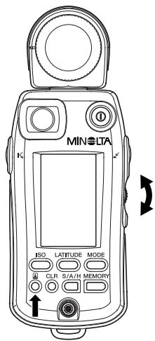
- Turning the control upward increases the film speed in increments of 1/3-stop. The maximum film speed is ISO 8000.
- Turning the control downward lowers the film speed in decrements of 1/3-stop. The minimum film speed is ISO 3.
- If you change the instant film speed after you take a measurement, the reading will be recalculated and displayed accordingly.
Selecting a measuring method suitable for the light-receiving method
Select a measuring method, either incident light measurement or spot measurement, appropriate to the shooting conditions and nature of the photograph. The Flash Meter VI can measure exposure in either way. For incident light measurement, select either the Spherical Diffuser or optional Flat Diffuser.
1. Incident light measurement
When performing incident light measurements, use the Spherical Diffuser for three-dimensional subjects such as portraits, and architectural or landscape photographs. Use the Flat Diffuser when you photograph flat surfaces such as documents or paintings, or when you want to measure lighting ratio (See page 58.).
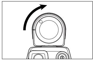
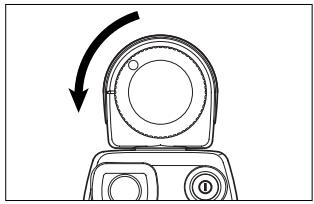
Attaching the Spherical Diffuser
Align the index mark (white circle) of the Spherical Diffuser with the index of the receptor head. Secure the diffuser by turning it in the direction indicated by the arrow until it stops.
Removing the Spherical Diffuser
Rotate the diffuser anticlockwise until it stops, and pull the diffuser to detach it.
To take an incident light measurement, position the meter near the subject and aim the Spherical Diffuser directly at the camera.
- The receptor can rotate through a range of 270 degrees, so that you can use the meter in an almost any photographic configuration.
WARNING
Never attempt to look directly at the sun through the viewfinder of the meter. Doing so will damage your eyesight.
CAUTION
Do not walk around while looking into the viewfinder. Doing so may result in a fall or other accident.
2. Spot measurement
To measure a specific area of a photographic image, select the spot measurement method (with a light-receiving angle of 1 degree).
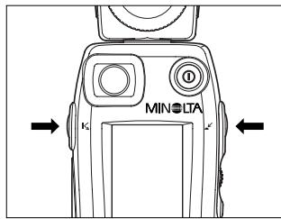
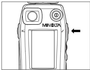
To take a spot measurement,
position the meter near the camera,
- look into the viewfinder at the front of the meter (data panel side),
- locate the measuring index (circle) at the center of the viewfinder within the desired measuring point of the subject, and
- press the spot measuring button.
The allowable measuring distance from the subject is 1.3m to infinity () .
FNo. 4E,8+18,8,8

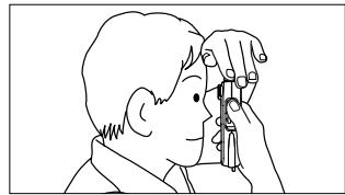
To stabilize your shooting posture and avoid shaking the meter, turn the receptor head toward the subject and hold the meter by placing your hand over it as shown above.
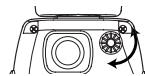
Dioptric adjustment
While looking into the viewfinder for a spot measurement, adjust the dioptic by turning the dioptic adjustment dial until the measuring index circle can be clearly seen.
Difference between incident-light and Spot (reflected-light) readings
Exposure can be measured in two basic ways. One way is to measure the light incident on the subject, i.e. the brightness of light illuminating the subject (illuminance) (see Fig. 1); the other is to measure the light Spot reflected by the subject, i.e. the intensity of the light reflected from the subject in the direction of the camera (luminance) (see Fig. 2).
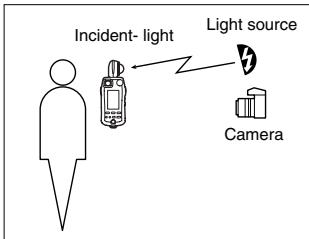
Fig. 1 Incident-light method
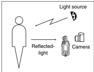
Fig. 2 Spot (Reflected-light) method
Before selecting the most suitable measuring method, you need to fully understand the different sources of light you are working with, as well as the influence of the positions and direction of receptors during measurement.
Incident-light readings
In general photography, light from the illuminating light source reflects off the subject and passes through the lens to form an image on the film, and to expose the film.
To accurately calculate exposure in incident-light readings, you need to know how much of the illuminating light is actually reflected from the object to the camera. To do this, you need to know how light or how dark the subject is, i.e. the reflectance of the subject.
Since a typical value of reflectance for many scenes is 18% *, this value is used to calculate the light intensity reflected from the subject towards the camera. The exposure reading (f-number and shutter speed) are then calculated to reproduce the metered area as a midtone with 18% reflectance.
Thus, incident-light readings are based on this standard value of 18% reflectance. This means that areas of subjects having a reflectance higher than 18% will turn out brighter (e.g. white), while areas of reflectance lower than 18% will turn out darker (e.g. black). This will produce a clear contrast in the picture of the subject. From this, we can see that this measuring method provides for natural tonal range over the entire composition.
- The value of "18%" has been determined to be a typical reflectance value for many different subjects.
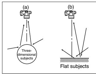
Fig. 3
To make effective incident-light exposure readings, you must use the Spherical Diffuser and Flat Diffuser creatively.
When photographing three-dimensional objects such as people, the highlights and shadow areas of a composition depend on the direction of the main illuminating light source. Exposure is also influenced by any light reflected towards the camera from the sides or rear of the subject (Fig. 3 (a)). In these situations, the Spherical Diffuser captures the illuminating light coming from different directions at the position of the subject, so that the exposure reading takes into account the contribution of this light on illuminating the subject. On the other hand, with flat subjects such as pictures and documents, light from the sides or rear of the subject generally make little or no contribution to illuminating the subject (Fig. 3(b)). So, for these situations, accurate exposure readings are made using a Flat Diffuser to capture only the illuminating light from the front of the subject.
Preparations
Spot (reflected-light) readings
Spot (reflected-light) exposure readings directly measure the amount of light (luminance) reflected from the subject to the camera. Unlike the case of incident-light readings, this method does not rely on the assumption of a standard subject reflectance of 18% . Based on the measured amount of light falling on the subject, the meter calculates the appropriate exposure value for reproducing the subject on film at a suitable medium density (midtone). This means that in Spot (reflected-light) readings, all subjects, regardless of their reflectance, i.e. regardless of whether they are bright or dark (white or black), will be reproduced at the same tonal density (midtone). For this reason, when making Spot (reflected-light) exposure readings, it is important to decide which area of the subject to measure, since the reflectance will generally vary quite widely over the composition under different conditions.
There are various advanced Spot (reflected-light) readings, such as the highlight standard exposure method, where an exposure reading is taken of a bright (white) part of the composition; the shadow standard exposure method, where a dark (black) part of the composition is measured; and a method for determining exposure by evaluating the contrast of the subject and then forecasting how it will come out on film. To make full use of Spot (reflected-light) readings, refer to specialist books and photo magazines. You will find that selective metering can give you very precise control over exposure.
Basic Operation
Here we explain the basics of using the MINOLTA FLASH METER VI to take exposure readings.
Select a measuring method
- Flash light refers to artificial momentary lighting from light sources such as electronic flashes, strobe flashes, and speed lights.
- Ambient light refers to continuous lighting from sources such as natural light (sunlight) and electric lights (including fluorescent lights).
- In either case, both incident-light exposure readings and spot-light exposure readings can be made.
Measuring ambient light
1. With a still camera
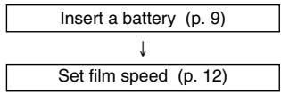
| Insert a battery (p. 9) |
| ↓ |
| Set film speed (p. 12) |
1 Prepare the meter to start taking readings.
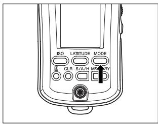
2 Press the MODE button to switch the mode display to AMBI.
- Changing the measuring mode retains the memory data but clears previous measurement data.
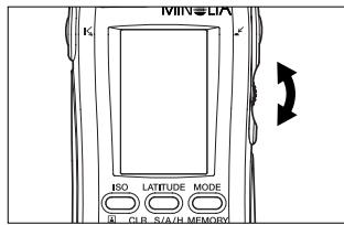
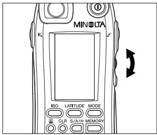
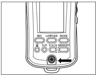
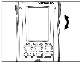
3 Specify the desired shutter speed with the up/down dial.
- Shutter speed can be set within the range of 30 min. to 1/16000 sec.
- Turning the up/down dial upward increases the shutter speed. Turning it downward lowers the shutter speed.
The shutter speed can also be changed after meter readings.

4 Press the measuring button to take readings.
- The meter takes measurements continuously as you hold down the incident light measuring button. The digital display on the data panel displays the measurement data. At the same time, the measurement data are also displayed on the dot indicator of the analog scale L. When the measuring button is released, the meter stops taking measurements and displays only the latest measurement result.
- The meter takes measurements continuously as you hold down the spot measuring button. The digital display in the viewfinder displays the measurement data. At the same time, the measurement data are also displayed on the dot indicator of the analog scale R. When the measuring button is released, the meter stops taking measurements. The latest measurement result appears on the digital display of the external data panel and on the dot indicator of the analog scale R display.
- Pressing the CLR button clears the measurement data.
Display example
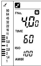
Display units are FNo.
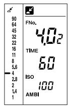
If you set your desired shutter speed, the f-number required for proper exposure at that shutter speed is displayed on the digital readout. The reading is also displayed on the analog scale by a pointer.
Ex.: The display shows a reading of F4.0+0.2-stops.
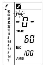
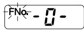
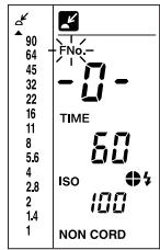
If the f-number reading is outside the meter's display range, "FNo." blinks and the display shows either "-O-" (over-range error) or "-U-" (under-range error). At the same time, the over-range/under-range error indicator ( or ) appears on the analog scale. If the reading is over the display range, reset the shutter speed to a faster value; if it's under the display range, reset to a slower shutter speed. In this way, you will be able to determine an appropriate combination of shutter speed and f-number.
Display units are EV
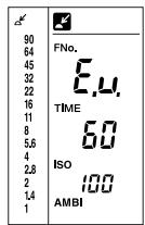
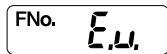
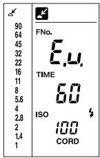
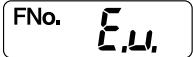
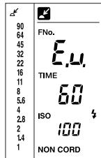
If the f-number reading exceeds or falls below the meter's measuring range, the display shows "E.o." (over-range error) or "E.u." (under-range error).
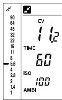
An exposure value is displayed regardless of the shutter speed setting. The dot indicator of the analog scale indicates the f-number corresponding to the shutter speed setting. Ex.: The display shows a reading of 11.2 (EV).
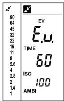
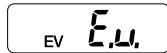
If the f-number reading exceeds or falls below the meter's measuring range, the display shows "E.o." (over-range error) or "E.u." (under-range error). E23
2. With a cine camera
Insert a battery (p. 9)
Set CINE mode (p. 72)
The default setting of TIME/CINE mode is "TIME." In the custom setting (Alt) mode, change "TIME" to "CINE."
Set film speed (p. 12)
1 Prepare the meter to start taking readings.
2 In CINE mode, the measuring mode is fixed to AMBI.
- Measuring mode cannot be changed.
3 Specify the frame rate of your camera with the up/down dial.
Eight framing-rates can be set: 8, 12, 16, 18, 24, 25, 30, 32, 64, and 128 frames/sec. (The appropriate shutter speed, corresponding to a shutter opening of 180^ , is set automatically by the exposure meter.)
If the opening of your camera's shutter is not 180^ , the film speed should be adjusted as follows:
Shutter opening and film speed adjustment
| Shutter opening | Film-speed adjustment |
| 160° | -1/3 |
| 220° | +1/3 |
-1/3: Set the film speed to 1/3 stop slower than the film speed you are using. (Ex.: ISO 400 to 320)
+1/3: Set the film speed to 1/3 stop faster than the film speed you are using. (Ex.: ISO 400 to 500)
4 Press the measuring button to take readings.
-
The meter takes measurements continuously as you hold down the incident light measuring button. The digital display on the data panel displays the measurement data. At the same time, the measurement data are also displayed on the dot indicator of the analog scale L. When the measuring button is released, the meter stops taking measurements and displays only the latest measurement result.
-
The meter takes measurements continuously as you hold down the spot measuring button. The digital display in the viewfinder displays the measurement data. At the same time, the measurement data are also displayed on the dot indicator of the analog scale R. When the measuring button is released, the meter stops taking measurements. The latest measurement result appears on the digital display of the external data panel and on the dot indicator of the analog scale R display.
Measuring flash light
1. With a sync cord
Insert a battery (p. 9)
Set film speed (p. 12)
1 Prepare the meter to start taking readings.
2 Press the MODE button to switch the mode display to CORD.
- Changing the measuring mode retains the memory data but clears previous measurement data.
- Settings for shutter speed and display units are automatically adjusted as follows.
1/1250 to 1/16000 sec.:
adjusted to 1/1000 sec.
EV: adjusted to FNo.
- Pressing the CLR button clears the measurement data.
- Display example is the same as the case of a still camera. (Refer to page 22.)
3 Attach the flash sync cord to the meter's sync terminal.
Take care when connecting the flash to the meter, as the flash may fire.
4 Specify the desired shutter speed with the up/down dial.
- Shutter speeds can be set within the range of 30 min. To 1/1000 sec. (The speed can be set within the flash sync speed range of your camera.)
- Turning the up/down dial upward increases the shutter speed. Turning it downward lowers the shutter speed.
The shutter speed can also be changed after meter readings.
5 Press the measuring button to take a reading.
- When the flash fires, the meter takes a single measurement and displays the measured value on the digital display. The reading is also displayed on the analog scale. The proportion of flash light illuminating the composition is shown on the analyze scale.
- Pressing the CLR button clears the measurement data.
If no flash is connected to the sync terminal, or if the flash does not fire normally because it is not fully charged, the meter cannot take a flash light measurement. Before starting measurement, make sure that the flash is connected to the sync terminal and the flash has been fully charged.
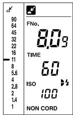
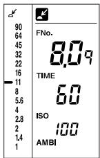
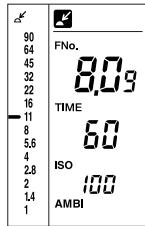
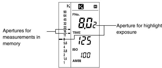
Display example
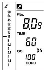
The f-number corresponding to the shutter speed set in step 4 is displayed on the digital readout as well as on the analog scale with a pointer () . The proportion of flash light illuminating the composition is shown on the analyze scale.
Example: The display shows a reading of F8.0 + 0.9 stops, and the proportion of ambient light to flash light is about 1:1.
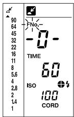
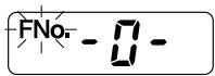
If the f-number reading is outside the meter's display range, "FNo." blinks and the display shows either " - O -" (over-range error) or " - U -" (under-range error). At the same time, the over-range/under-range error indicator (▲ or▼) appears on the analog scale.
If the f-number reading exceeds or falls below the meter's measuring range, the display shows "E.o." (over-range error) or "E.u." (under-range error).
★ When measuring flash light using a sync cord (CORD mode), the flash may fail to fire (e.g. if the trigger voltage of the flash is too low). In this case, take a reading without sync firing the flash (NON CORD mode).
2. Without a sync cord (Incident light measurement)
1 Prepare the meter to start taking readings.
2 Set the mode display to NON CORD using the MODE button.
- Changing the measuring mode retains the memory data but clears previous measurement data.
- Settings for shutter speed and display units will be automatically adjusted as follows. 1/1250 to 1/16000 sec.: adjusted to 1/1000 sec. EV: adjusted to FNo.
3 Specify the desired shutter speed with the up/down dial.
- Shutter speeds can be set within the range of 30 min. to 1/1000 sec. (Set the shutter speed within the flash sync speed range of your camera.)
- Turning the up/down dial upward increases the shutter speed. Turning it downward lowers the shutter speed.
The shutter speed can also be changed after meter readings.
4 Press the incident light measuring button.
- The NON CORD mode symbol blinks to indicate that the meter is waiting for the flash to take a reading.
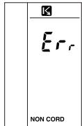
- In NON CORD mode, the meter cannot take a spot measurement.
Pressing the spot measuring button displays the error code ("Err").
Pressing the incident light measuring button cancels the error code and sets the meter to standby state. The error code is canceled after about five seconds or as soon as another button is pressed.
5 Fire the flash to take a reading.
- The meter detects the light of the flash and reads and displays the exposure on the digital readout. The measured value is also displayed on the dot indicator of the analog scale, and the proportion of flash light is indicated on the analyze scale.
- Pressing the CLR button clears the measured value.
To take further readings, repeat the process from step 4.
- If the flash does not fire within approx. one minute after the meter goes into flash waiting mode, or if you press any button other than the measuring button during this time, the NON CORD mode symbol will stop blinking (stay on). Then, even if you fire the flash, no reading will be made.
To restore the meter to standby state, press the incident light measuring button again.
- In the standby state, the meter may mistake ambient light from an intermittent light source (such as a fluorescent light) for flash light, depending on the type of ambient light. To avoid this risk, take readings in CORD mode using a synch cord.
Fire the flash according to the directions given in the users' manual for the flash.
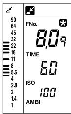
Display example
The f-number corresponding to the shutter speed set in step 3 is displayed on the digital readout as well as on the analog scale with a pointer () .
Example: The display shows a reading of F8.0 + 0.9 stops, and the proportion of ambient light to flash light is about 1:1.
If the f-number reading is outside the meter's display range, "FNo." blinks and the display shows either " - O -" (over-range error) or " - U -" (under-range error). At the same time, the over-range/under-range error indicator (▲ or▼) appears on the analog scale.
If the f-number reading exceeds or falls below the meter's measuring range, the display shows "E.o." (over-range error) or "E.u." (under-range error). E35
Light Ratio Analyze function
For flash light measurement, the Flash Meter VI uses a method of measuring flash light/ambient light separately.
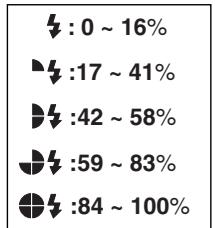
The proportion of ambient light and flash light to the total exposure is indicated on the quadrant analyze scale.
How to read the flash/ambient light ratio
Whenever you take a flash light reading, the analyze scale is displayed on the LCD data panel. After a reading, you can also do a simulation to see how changes to the shutter speed affect the proportions of ambient light and flash light.
The analyze scale shows the proportion of flash light in the total exposure reading as one of five levels.
Example of reading, display and simulation
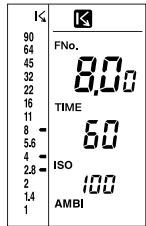
Assume that a tungsten lamp is used as the ambient light source.
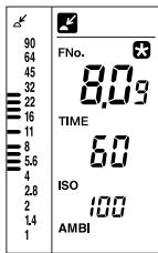
Reading of F2.8o at a shutter speed of 1/60 sec.
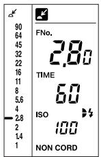
Two quadrants are lit up on the display, indicating that the proportion of flash light is approx. 50% (ambient:flash ratio = 1:1 ).
A photograph taken under these conditions will not be strongly influenced by either the tungsten light (orange) or the flash light (white).
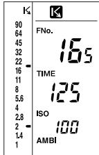
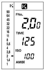
Using the up/down dial to change the shutter speed to 1/15, we can see how this change will affect the mix of ambient and flash light.
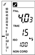
The aperture has changed to F4.03 and now, only one quadrant is lit up. This indicates that the proportion of flash light is now only 25% (ambient:flash ratio = 3:1 ).
A photograph taken under these conditions will be influenced more strongly by the tungsten light (orange) and less strongly by the flash light (white).
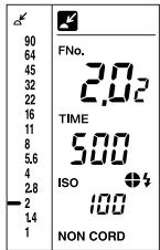
On the other hand, increasing the shutter speed (within the range of sync) will have the opposite effect-photos will be more strongly influenced by flash light (white) than ambient light.
This simulation is based on controlling the ambient light by varying the shutter speed. The proportions of ambient light and flash light can also be adjusted by changing the intensity of the flash light.
The intensity of flash light can be controlled either by varying the distance between the subject and the flash, or by changing the power (light output) of the flash.
When you are controlling flash light intensity, you must take a new reading each time one of these two factors is changed.
Special Functions
Here we explain how to use the special functions of the MINOLTA FLASH METER VI.
Latitude display function
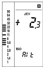
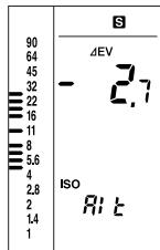
Generally, with a color slide film, the film latitude range that ensures linearity of exposure and density is about 5 to 6 EV. The analog scale L of the Flash Meter VI can display the standard exposure and the latitude range based on the standard exposure. By comparing the readings on the analog scales, you can check graphically whether the exposures of highlights and shadowed areas determined by spot measurement are within the latitude range.
The meter's initial latitude setting is +2.3 EV to -2.7 EV, relative to the standard exposure. These settings can be changed in custom settings mode.
For details of custom settings mode, see p.66.
The LATITUDE display function is related to the S/A/H
(shadow/average/highlight) exposure calculation function (p. 45) and the brightness difference function (p. 52). The following provide a thorough description of these functions.
1 Take a measurement. Press the LATITUDE button.
The indicator appears, and the measured value is fixed. The latitude based on this measured value is displayed on the dot indicator of the analog scale L.
- Pressing the LATITUDE button while holding down the S/A/H button causes the latitude to be based on the standard exposure calculated from memory data according to S, A or H mode, instead of the current measurement result.
2 Press the measuring button to take a measurement of the desired measuring area.
While the measuring button is held down, the meter continuously takes measurements and displays the exposure difference between the measured value and the standard exposure described in Step 1. When the measuring button is released, the standard exposure is displayed. See the description of the "Brightness difference function" on p. 52.
- Pressing the LATITUDE button again cancels the latitude display mode and causes the latest measurement data to be displayed.
- Pressing the CLR button cancels latitude display mode and clears the measurement data and standard exposure.
Combining incident light measurement and spot measurement
The Flash Meter VI offers a comparative display of the results of incident light measurement and spot (reflected light) measurement. Used with the latitude display function, the meter provides a clear and simple graphical decision process for determining an exposure suited to the nature of the photograph.
Take an incident light measurement to determine the standard exposure.
2 Press the LATITUDE button to select latitude display mode.
A latitude based on the standard exposure measured in Step 1 is displayed on the dot indicator of the analog scale L.
3 Take a spot measurement of the area of the subject to be emphasized, such as the highlight or shadow areas, and store the measured values in memory.
The result of the spot measurement is displayed on the pointer of the analog scale R. If the measurement result is outside the latitude range, the dot indicator blinks.
While holding down the spot measuring button, you can monitor the deviation from the standard exposure in the viewfinder display with a precision of 0.1 EV. (See p. 52.) If the measurement result is outside the latitude range, the EV indicator blinks.
4 By comparing the spot measurement result displayed on the analog scale R with the latitude displayed on the analog scale L, you can ensure that the exposure of the spot you are emphasizing is within the latitude range.
If the measurement result is outside the latitude range, adjust the lighting conditions and take another spot measurement.
Memory function
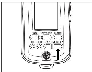
To store measurement data in memory of the Flash Meter VI, simply press the MEMORY button. Up to ten pieces of data (including incident light measurement data and spot measurement data) can be stored.
To display the incident light measurement data stored in memory on the pointer of the analog scale L, simply press the incident light measuring button. To display the spot measurement data stored in memory on the pointer of the analog scale R, simply press the spot measuring button. With the memory function, you can check the lighting ratio graphically on the analog scale. This function is useful for lighting adjustments. (See p. 58.)

Press the CLR button to clear existing memory data.
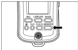
2 After taking the first measurement, press the MEMORY button.
- Press and hold the MEMORY button to display the number of measurement results stored in memory.
When the MEMORY button is released, the measured value is stored in memory and the pointer corresponding to the measured value light up.
3 After taking the second measurement, press the MEMORY button to store the second measurement result in memory. Repeat the above steps as many times as required.
- Press and hold the MEMORY button to display the number of measurement results stored in memory.
The measured value is displayed on the digital display. If the latest measurement is an incident light measurement, the pointers corresponding to the measured value on the digital display appear on the analog scale L. If it is a spot measurement, the pointers corresponding to the measured value on the digital display appear on the analog scale R.
The memory data from the latest measuring method are displayed on the pointer. If the latest measurement is an incident light measurement, the memory data on incident light measurement are displayed on the pointer of the analog scale L. If it is a spot measurement, the memory data on spot measurement are displayed on the pointer of the analog scale R.
Example: When the latest measurement is a spot measurement:
Data on up to ten measurements can be stored in memory.
The pointer of the analog scale can simultaneously display data on up to eleven measurements (including ten measurements in memory and the one measurement taken most recently).
- If the memory contains data on ten measurements, pressing the MEMORY button again causes the "Err" code to be displayed while the MEMORY button is being pressed. The current data will not be stored in memory.
- If you change film speed or shutter speed after pressing the MEMORY button, the stored values are changed accordance to the new setting. (These changes are also reflected on the analog scale.)
- If there is no reading on the digital readout, or if the current reading is out of the meter's measurement range, pressing the MEMORY button does not have any effect.
To delete all values from memory, press the CLR button.
S/A/H (Shadow/Average/Highlight) calculations
The Flash Meter VI provides three types of exposure calculations (highlight-based exposure, shadow-based exposure, and average exposure) suited to the nature of the photographic image. These are based on spot measurements of specific areas of the subject. The average exposure calculating function also works for incident light measurement. For incident light measurement, exposure calculation is based on incident light measurement memory data. For spot measurement, it is based on spot measurement memory data.
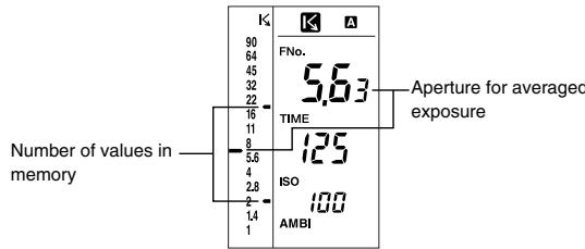
Average exposure
For spot measurement, the meter calculates the average of the maximum and minimum measurements stored in memory.
For incident light measurement, the meter calculates an average exposure from up to ten measurements stored in memory.
Take measurements of up to ten points on the subject, including highlight and shadow areas, and store the measurement data in memory.
2 Set the calculation mode to "A" with the up/down dial while pressing the S/A/H button.
-
When the incident light measurement is selected, the calculation mode is automatically set to "A". (It cannot be set to "S" or "H".) A measured value cannot be used for the average exposure calculation unless it has been stored in memory.
-
Hold down the S/A/H button to display the average of the memory data on the digital display and on the pointer of the analog scale (L).
While the S/A/H button is held down:
- If there is no value in memory and the current measurement value is displayed on the digital readout: the measurement value is stored in memory and used in average exposure calculations.
- If there is no value in memory and no reading on the digital readout: no exposure value is calculated.
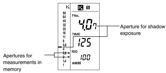
Shadow calculations (for spot readings only)
When you want to reproduce some detail in the darkest areas of a composition (shadow areas) without blocking them out, take a spot reading of the shadow area and use the meter's shadow exposure calculation function to determine the appropriate exposure for the shot.
1 Take a reading of the highlight area of the subject.
2 While holding down the S/A/H button, set the calculation mode to "S" with the up/down dial.
- Hold down the S/A/H button to view the result of the shadow-based exposure calculation on the digital display and on the dot indicator of the analog scale L.
- If there are any measurement values already stored in memory, the meter will determine the exposure for the darkest area measured and stored in memory. The meter can only make shadow exposure calculations with measurements stored in memory. If there are no measurements stored in memory, the meter determines the appropriate exposure based on the latest measurement (displayed reading).
- If you take photographs according to the aperture given by the shadow exposure calculation, the shadow areas will be accurately reproduced on film as shadows (lower latitude).
While the S/A/H button is held down:
- In the above example, the shadow exposure for the darkest measured area (aperture: F2.0 + 0.0 ) was determined.
Highlight calculations (for spot readings only)
When you want to reproduce some detail in the brightest areas of a composition (highlight area), without washing them out, take a spot reading of the highlight area and use the meter's highlight exposure calculation function to determine the appropriate exposure.
1 Take a reading of the highlight area of the subject.
2 While holding down the S/A/H button, set the calculation mode to "H" with the up/down dial.
- Hold down the S/A/H button to display the result of the highlight-based exposure calculation on the digital display and on the dot indicator of the analog scale L.
- If there are any measurement values already stored in memory, the meter will determine the exposure for the brightest area measured and stored in memory. The meter can only make highlight exposure calculations with measurements stored in memory. If there are no measurements stored in memory, the meter determines the appropriate exposure based on the latest measurement (displayed reading).
- If you take photographs according to the aperture given by the highlight exposure calculation, the highlight areas will be accurately reproduced on film as highlights (upper latitude).
While the S/A/H button is held down:
- In the above example, the highlight exposure for the brightest area measured (aperture: F16+0.5 stops) was determined.
Brightness difference function
To fix the displayed measurement result or calculation result, press the LATITUDE button after taking an ordinary measurement or while holding down the S/A/H button. When the next measurement is taken with the meter, the exposure difference between the fixed measurement/calibration result and the new measurement result appears on the digital display. This function is useful for photography, with the measurement value and the aperture value taken by holding the S/A/H button or for ordinary measurement. It allows you to quickly check the brightness differences between one part of a composition and another, (e.g. front and background), or to measure the unevenness of illumination over a scene, by directly showing exposure differences between the current reading and a reference exposure value (previous measurement value or aperture value fixed using the LATITUDE button). This function can also be used for directly measuring the lighting ratio of a scene, by showing the exposure difference between the shadow and highlight areas of a composition, for highly precise lighting designs.
- The brightness difference function can be used in AMBI mode and CORD mode. Exposure differences cannot be displayed in NON CORD mode, even if you take readings.
- Displayable range of exposure differences is ± 10.0Ev (0.1Ev steps).
Measuring brightness difference relative to an exposure reading
1 Take a reading and then press the LATITUDE button.
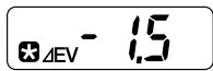
turns on to indicate the measurement value is fixed. (In this case, the fixed measurement value is F8.0 + 0.9 -stops.)
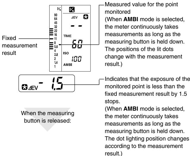
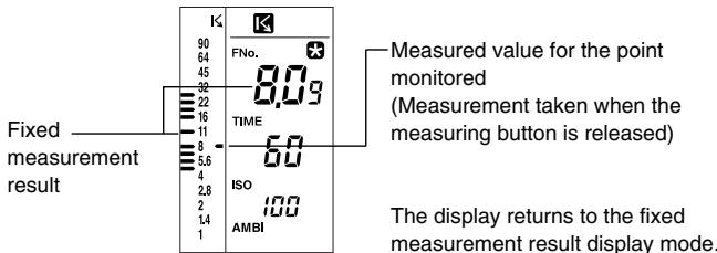
2 Press the measuring button to take a reading of the area whose brightness you want to compare with the fixed value.
The measurement result will not appear on the viewfinder display if the incident light measuring button is pressed.
The measurement result will appear on the viewfinder display if the spot measuring button is pressed. The external data panel displays "- - - - "
In AMBI mode
- Pressing the incident light measuring button or the spot measuring button takes continuous readings. As each reading is taken, the exposure difference between the current measurement value and the fixed measurement value of step 1 is displayed. When you release the measuring button, the fixed reference value of step 1 is displayed.
In CORD mode
Each time you press the incident light measuring button or the spot measuring button, the flash is fired and a single exposure reading is taken. While the measuring button is pressed, the exposure difference between the current measurement value and the fixed measurement value of step 1 is displayed. When you release the measuring button, the fixed measurement value of step 1 is displayed again. (The data panel display is the same in AMBI mode.)
- If you press the LATITUDE button, the display reverts to normal display mode. (The value measured in step 1 is stored in memory.)
- Pressing the CLR button cancels latitude display mode and clears the measurement data and standard exposure.
If the incident light measuring button is used to take the measurement described in Step 1 and to monitor the exposure difference:
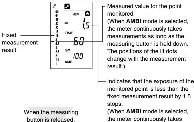
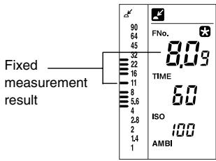
The display returns to the fixed measurement result display mode.
If the spot measuring button is used to take the measurement described in Step 1 and to monitor the exposure difference:
Monitoring exposure difference after shadow-based exposure calculation
1 Take a spot measurement of the shadow area of the subject.
2 While holding down the S/A/H button, set the calculation mode to "S" with the up/down dial.
3 Press the LATITUDE button while holding down the S/A/H button.
| K4 | K5 |
| 90 | FNo. |
| 64 | 407 |
| 45 | TIME |
| 32 | ISO |
| 22 | AMBI |
| 16 | |
| 11 | |
| 8 | |
| 5.6 | |
| 4 | |
| 2.8 | |
| 2 | |
| 1.4 | |
| 1 |
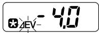
The indicator appears and the calculated standard exposure is fixed. (In this case, the standard exposure is fixed to F4.0 +0.7 stops.)
- The difference from highlight-based exposure and average exposure for spot measurement, and from average-based exposure for incident light measurement, can be displayed in the same manner.
4 Press the measuring button to take a reading of the area whose brightness you want to compare with the fixed value.
The measurement result will not appear on the viewfinder display if the incident light measuring button is pressed.
The measurement result will appear on the viewfinder display if the spot measuring button is pressed. The external data panel displays "---".
AMBI mode
- When the incident light measuring button or spot measuring button is held down, the meter continuously takes measurements and displays the difference between the measurement result and the exposure determined in Step 3. When the measuring button is released, the exposure determined in Step 3 is displayed.
CORD mode
Each time the incident light measuring button or spot measuring button is pressed, the flash fires and the meter takes a single measurement. While the measuring button is held down, the difference between the measurement result and the exposure determined in Step 3 is displayed. When the measuring button is released, the exposure determined in Step 3 is displayed. (The indication on the data panel is the same as that for AMBI mode.)
Press the LATITUDE button to return the meter to the original measurement display mode.
- Pressing the CLR button cancels latitude display mode and clears the measurement data and standard exposure.
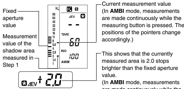
When the measuring button is released:
- This shows that the currently measured area is 2.0 stops brighter than the fixed aperture value. (In AMBI mode, measurements are made continuously while the measuring button is pressed. The reading on the digital readout changes accordingly.)

The display returns to the fixed exposure calculation display mode.
Measuring lighting ratio using the Flat Diffuser
The lighting ratio is the brightness ratio between the highlight and shadow areas of a composition. For example, if the difference in measurement values (exposure difference) obtained by an incident light measurement is one stop, the lighting ratio is 2:1; if it's two stops, the ratio is 4:1. In general, lighting ratios from 4:1 to 8:1 (exposure difference of 2 to 3 stops) are considered best when using color films, since these ratios allow colors to be reproduced naturally.
By adjusting the lighting ratio, you can control the subject's highlight-to-shadow relationship or the relationship between the main subject and the background when photographing people or objects in a studio.
To check lighting characteristics such as the brightness difference between a main subject and background, a Spherical Diffuser can be used in most cases. However, if a subject is receiving light from different directions, it is necessary to measure the brightness of the individual light sources illuminating it, using a Flat Diffuser (incident light measurement, see page 14).
This allows control over the shadow areas of the main subject. By replacing a Spherical Diffuser with a Flat Diffuser, the brightness of light sources illuminating a subject can be measured individually, and the lighting ratio can be checked easily. In addition, you can use the meter's memory function and brightness difference function to read these values easily.
1 Attach a Flat Diffuser to the receptor of the instrument. See page 14 for details on how to attach a Flat Diffuser.
2 Prepare the meter for taking a reading.
3 Set the measuring mode with the MODE button according to the light source to be measured.
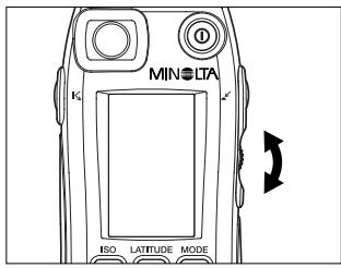
4 Specify the desired shutter speed with the up/down dial.
Press the incident light measuring button while holding the meter near the subject with the Flat Diffuser facing the main light source.
6 Press the MEMORY button to store the measurement value.
7 Press the incident light measuring button while holding the meter near the subject with the Flat Diffuser facing the fill light source.
- Block out all light from the main light source with your hands or other means, so that it does not directly fall on the Flat Diffuser, or if possible, turn off the main light source.
The two pointers on the analog scale L indicate the brightness of the main light source and the brightness of the fill light source.
- Read the difference in exposure of the two values.
The reading accuracy of the analog scale L is 0.5 stops.
Using the brightness difference function of the instrument, the lighting ratio can be read with an accuracy of 0.1 stops.
Alternatively, instead of storing the readings in memory, as explained in step 6 on page 60, the following method can be used:
6 Press the LATITUDE button. 3 is displayed on the data panel, and the exposure reading for the main light source is fixed.
7 Take a reading with the Flat Diffuser facing towards the fill light source. While holding down the incident light measuring button, the difference (or lighting ratio) between the fill light source exposure and main light source exposure, which was fixed in step 6, is displayed directly on the digital readout. Read the value.
The lighting ratio of main light source to fill light source can be calculated from the following table.
Table for determining lighting ratio
| Brightness differences (exposure differences) | Brightness ratio between main light source and fill light source (lighting ratio) |
| + 1.0 (1 stop) | 2:1 |
| + 2.0 (2 stops) | 4:1 |
| + 3.0 (3 stops) | 8:1 |
| + 4.0 (4 stops) | 16:1 |
| + 5.0 (5 stops) | 32:1 |
| + 6.0 (6 stops) | 64:1 |
| + 7.0 (7 stops) | 128:1 |
The formula for calculating the lighting ratio is:
Main light: Fill light = 2 Difference: 1
"Difference" can be either brightness difference in ± EV or difference in stops between apertures.
Using the Flash Meter VI as a simplified illuminance meter
Attach the Flat Diffuser (ptional accessory), to the meter. In AMBI mode, hold the Flat Diffuser parallel to the surface you want to measure. Then, press the incident light measuring button and read the EV value from the meter. Now, look up the approximate illuminance from the EV-Ix conversion table on the next page.
- Film speed is set to ISO100 (p. 12) and display units are set to EV (p. 69).
- If the instrument has been recalibrated, set it back to the standard setting of 0 using Alt mode.
If you need to measure illuminance precisely, use the MINOLTA DIGITAL ILLUMINANCE METER T-10, which is designed specifically for this function.
Using the Flash Meter VI as a simplified luminance meter
The Flash Meter VI can also function as a simplified luminance meter. To determine approximate luminance, press the spot measuring button in AMBI mode to take a measurement of the desired area of the subject. Read the resulting EV value in the EV-cd/m² conversion table.
- Film speed is set to ISO100 (p. 12) and display units are set to EV (p. 69).
-
If the instrument has been recalibrated, set it back to the standard setting of 0 using Alt mode.
To determine accurate luminance, use the LS-100/LS-110 Minolta Luminance Meter, a dedicated luminance measuring device. -
EV-lx conversion table (with Flat Diffuser attached)
| Decimal integral | .0 | .1 | .2 | .3 | .4 | .5 | .6 | .7 | .8 | .9 |
| -2 | 0.63 | - | - | - | - | - | - | - | - | - |
| -1 | 1.3 | 1.2 | 1.1 | 1.0 | 0.9 | 0.9 | 0.8 | 0.8 | 0.7 | 0.7 |
| -0 | 2.5 | 2.3 | 2.2 | 2.0 | 1.9 | 1.8 | 1.7 | 1.5 | 1.4 | 1.3 |
| +0 | 2.5 | 2.7 | 2.9 | 3.1 | 3.3 | 3.5 | 3.8 | 4.1 | 4.4 | 4.7 |
| 1 | 5.0 | 5.4 | 5.7 | 6.2 | 6.6 | 7.1 | 7.6 | 8.1 | 8.7 | 9.3 |
| 2 | 10 | 11 | 12 | 12 | 13 | 14 | 15 | 16 | 17 | 19 |
| 3 | 20 | 21 | 23 | 25 | 26 | 28 | 30 | 33 | 35 | 37 |
| 4 | 40 | 43 | 46 | 49 | 53 | 57 | 61 | 65 | 70 | 75 |
| 5 | 80 | 86 | 92 | 99 | 110 | 110 | 120 | 130 | 140 | 150 |
| 6 | 160 | 170 | 180 | 200 | 210 | 230 | 240 | 260 | 280 | 300 |
| 7 | 320 | 340 | 370 | 390 | 420 | 450 | 490 | 520 | 560 | 600 |
| 8 | 640 | 690 | 740 | 790 | 840 | 910 | 970 | 1000 | 1100 | 1200 |
| 9 | 1300 | 1400 | 1500 | 1600 | 1700 | 1800 | 1900 | 2100 | 2200 | 2400 |
| 10 | 2600 | 2700 | 2900 | 3200 | 3400 | 3600 | 3900 | 4200 | 4500 | 4800 |
| 11 | 5100 | 5500 | 5900 | 6300 | 6800 | 7200 | 7800 | 8300 | 8900 | 10000 |
| 12 | 10000 | 11000 | 12000 | 13000 | 14000 | 15000 | 16000 | 17000 | 18000 | 19000 |
| 13 | 21000 | 22000 | 24000 | 25000 | 27000 | 29000 | 31000 | 33000 | 36000 | 38000 |
| 14 | 41000 | 44000 | 47000 | 50000 | 54000 | 58000 | 62000 | 67000 | 71000 | 76000 |
| 15 | 82000 | 88000 | 94000 | 100000 | 110000 | 120000 | 120000 | 130000 | 140000 | 150000 |
| 16 | 160000 | 180000 | 190000 | 200000 | 220000 | 230000 | 250000 | 270000 | 290000 | 310000 |
| 17 | 330000 | 350000 | 380000 | 400000 | 430000 | 460000 | 500000 | 530000 | 570000 | 610000 |
| 18 | 660000 | 700000 | 750000 | 810000 | 860000 | 930000 | 990000 | 1100000 | 1100000 | 1200000 |
How to read the EV-lx conversion table
The EV-lx conversion table lists the integer component of EV values vertically and the decimal fraction components of EV values horizontally. For example, if the meter displays a reading of EV 10.2, the row for the integer 10 and the column for the decimal 0.2 intersect at 2900 lx, the corresponding approximate illuminance value.
EV-cd/m² conversion table
| Decimal integral | .0 | .1 | .2 | .3 | .4 | .5 | .6 | .7 | .8 | .9 |
| 1 | 0.28 | 0.30 | 0.32 | 0.34 | 0.37 | 0.40 | 0.42 | 0.45 | 0.49 | 0.52 |
| 2 | 0.56 | 0.60 | 0.64 | 0.69 | 0.74 | 0.79 | 0.85 | 0.91 | 0.98 | 1.0 |
| 3 | 1.1 | 1.2 | 1.3 | 1.4 | 1.5 | 1.6 | 1.7 | 1.8 | 2.0 | 2.1 |
| 4 | 2.2 | 2.4 | 2.6 | 2.8 | 3.0 | 3.2 | 3.4 | 3.6 | 3.9 | 4.2 |
| 5 | 4.5 | 4.8 | 5.1 | 5.5 | 5.9 | 6.3 | 6.8 | 7.3 | 7.8 | 8.4 |
| 6 | 9.0 | 9.6 | 10 | 11 | 12 | 13 | 14 | 15 | 16 | 17 |
| 7 | 18 | 19 | 21 | 22 | 24 | 25 | 27 | 29 | 31 | 33 |
| 8 | 36 | 38 | 41 | 44 | 47 | 51 | 54 | 58 | 62 | 67 |
| 9 | 72 | 77 | 82 | 88 | 95 | 100 | 110 | 120 | 120 | 130 |
| 10 | 140 | 150 | 160 | 180 | 190 | 200 | 220 | 230 | 250 | 270 |
| 11 | 290 | 310 | 330 | 350 | 380 | 410 | 430 | 470 | 500 | 540 |
| 12 | 570 | 610 | 660 | 710 | 760 | 810 | 870 | 930 | 1000 | 1100 |
| 13 | 1100 | 1200 | 1300 | 1400 | 1500 | 1600 | 1700 | 1900 | 2000 | 2100 |
| 14 | 2300 | 2500 | 2600 | 2800 | 3000 | 3200 | 3500 | 3700 | 4000 | 4300 |
| 15 | 4600 | 4900 | 5300 | 5600 | 6100 | 6500 | 7000 | 7500 | 8000 | 8600 |
| 16 | 9200 | 9800 | 11000 | 11000 | 12000 | 13000 | 14000 | 15000 | 16000 | 17000 |
| 17 | 18000 | 20000 | 21000 | 23000 | 24000 | 26000 | 28000 | 30000 | 32000 | 34000 |
| 18 | 37000 | 39000 | 42000 | 45000 | 48000 | 52000 | 56000 | 60000 | 64000 | 68000 |
| 19 | 73000 | 79000 | 84000 | 90000 | 97000 | 100000 | 110000 | 120000 | 130000 | 140000 |
| 20 | 150000 | 160000 | 170000 | 180000 | 190000 | 210000 | 220000 | 240000 | 260000 | 270000 |
| 21 | 290000 | 310000 | 340000 | 360000 | 390000 | 420000 | 450000 | 480000 | 510000 | 550000 |
| 22 | 590000 | 630000 | 670000 | 720000 | 770000 | 830000 |
How to read the EV-cd/m² conversion table
The EV-cd/m² conversion table lists the integer component of EV values vertically and the decimal fraction components of EV values horizontally. For example, if the meter displays a reading of EV 10.2, the row for the integer 10 and the column for the decimal 0.2 intersect at 160cd / m^2 , the corresponding approximate luminance value.
Custom settings mode (Alt mode)
The operation settings of the Flash Meter VI, such as exposure correction value and shutter speed increment settings, can be customized to suit your preferences.
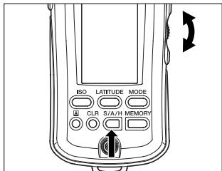
Selecting Alt mode
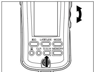
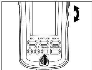
To set the meter to "Alt" mode, turn on the power by pressing the POWER button while holding down either the incident light measuring button, spot measuring button, ISO button, S/A/H button, LATITUDE button or MODE button.
In "Alt" mode, you can change the settings with the incident light measuring button, spot measuring button, or the ISO, S/A/H, LATITUDE and MODE buttons. Use the up/down dial to change the preset values. To register the custom settings, turn off the power after entering or selecting the desired values.
| Setting | Operation | Setting range | Default setting |
| Exposure correction value (for incident light measurement) | Incident light measuring button + Power-ON | -10.0 to +10.0 | 0 |
| Exposure correction value (for spot measurement) | Spot measuring button + Power-ON | -10.0 to +10.0 | 0 |
| Shutter speed increments | ISO button + Power-ON | 1, 1/2, 1/3 | 1 |
| Display unit | S/A/H button + Power-ON | FNo. + fraction, FNo. direct reading, EV | FNo. + fraction |
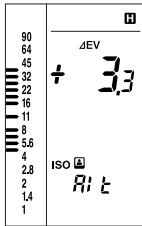
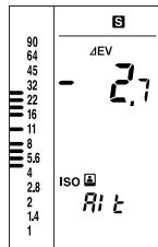
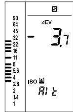
| Latitude | LATITUDE button + Power-ON | H: +0.1 to +10.0 | +2.3 |
| S: -0.1 to -10.0 | -2.7 | ||
| H: +0.1 to +10.0 | +2.3 | ||
| S: -0.1 to -10.0 | -2.7 | ||
| TIME/CINE | MODE button + Power-ON | TIME, CINE | TIME |
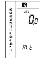
1) Exposure correction value
This sets the exposure correction value. The set value is displayed when you turn the power on.
You can adjust this setting to recalibrate the meter to your choice of exposure values
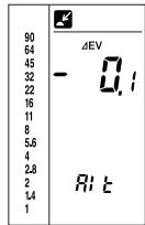
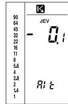
1 To specify an exposure correction value for incident light measurement, turn on the power while pressing the incident light measuring button. To specify an exposure correction value for spot measurement, turn on the power while pressing the spot measuring button. You can also specify a correction value for each measurement mode by pressing the corresponding measuring button in Alt mode.
2 Specify an exposure correction value with the up/down dial.
The displayed value can be changed in 0.1-EV increments/decrements. The setting range is ± 10.0Ev
- Once an exposure correction value is changed, it is reflected in the data stored in memory.
After an exposure correction value has been specified, the set value is displayed for 0.5 seconds at power-on. After correction values for both incident light measurement and spot measurement have been specified, these settings are displayed for 0.5 seconds each in sequence.
Correction value Correction value for incident light for spot measurement measurement

Correction value Correction value for incident light for spot measurement measurement
2) Shutter speed increments
Choose between increments of 1/2-stop, 1/3-stop and 1-stop, according to the shutter speed settings your camera.
1 Turn the power on while pressing the ISO button, or press the ISO button in Alt mode.
| 90 | |
| 64 | |
| 45 | |
| 32 | |
| 22 | |
| 16 | |
| 11 | |
| 8 | TIME |
| 5.6 | |
| 4 | |
| 2.8 | |
| 2 | |
| 1.4 | |
| 1 |
2 Turn the up/down dial to set the step value.
- Choose from values of 1.0 (1), 0.5 (1/2) and 0.3 (1/3).
| 90 | |
| 64 | |
| 45 | |
| 32 | |
| 22 | |
| 16 | |
| 11 | TIME |
| 8 | 0.3 |
| 5.6 | |
| 4 | |
| 2.8 | |
| 2 | RI t |
| 1.4 | |
| 1 |
3) Display unit
Select the desired display unit.
1 Turn on the power while pressing the S/H/A button, or press the S/H/A button in Alt mode.
2 Select the desired display unit with the up/down dial.
- Select any of the following display modes:
| 90 | |
| 64 | FNo. |
| 45 | |
| 32 | |
| 22 | |
| 16 | |
| 11 | |
| 8 | |
| 5.8 | |
| 4 | |
| 2.8 | |
| 2 | |
| 1.4 | |
| 1 |
| 90 64 45 32 22 16 11 8 5.6 4 2.8 2 1.4 1 | FNo. |
| 90 | |
| 64 | EV |
| 45 | CQs |
| 32 | |
| 22 | |
| 16 | |
| 11 | |
| 8 | |
| 5.6 | |
| 4 | |
| 2.8 | |
| 2 | |
| 1.4 | RI上 |
| 1 |
FNo. 00o:
Displays intermediate readings between f-numbers as FNo. + 1/10 stops.
FNo. 0.0:
Displays direct reading of an intermediate reading between f-numbers. (e.g., F3.5, F4.5)
EV 00.o:
Displays an EV value in 1/10-stop increments.
The pointer of the analog scale displays "FNo," even when the display unit is set to "EV."
- When CORD or NON CORD mode is selected, the display mode is set to "FNo.00o".
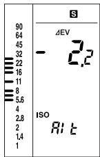
4) Latitude
- Specify an upper limit (H) and lower limit (S) for latitude display mode.
- Specify a shift value (H) for highlight-based exposure calculation and a shift value (S) for shadow-based exposure calculation.
1 Turn on the power while pressing the LATITUDE button, or press the LATITUDE button in Alt mode.
2 Specify the H value with the up/down dial.
| 90 64 45 32 22 16 11 8 5.6 4 2.8 2 1.4 1 |
3 Press the LATITUDE button.
4 Specify the S value with the up/down dial.
5 Press the LATITUDE button.
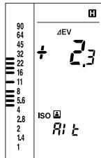
6 Specify the H value for instant film with the up/down dial.
7 Press the LATITUDE button.
8 Specify the S value for instant film with the up/down dial.
Press the LATITUDE button again to return to Step 2.
Switches between shutter speed and framing-rate in AMBI mode Note that it is not possible to switch to another measuring mode (CORD or NON CORD) while the framing-rate setting is active.
1 Turn the power on while pressing the MODE button, or press the MODE button while in Alt mode.
2 Turn the up/down dial to set the shutter-speed or framing-rate value you desire.
- Select either TIME or CINE mode.
TIME display
| 90 | |
| 64 | |
| 45 | |
| 32 | |
| 22 | |
| 16 | |
| 11 | TIME |
| 8 | 30 |
| 5.5 | Rt |
| 4 | |
| 2.8 | |
| 2 | |
| 1.4 |
CINE display
| 90 | |
| 64 | |
| 45 | |
| 32 | |
| 22 | |
| 16 | |
| 11 | |
| 8 | |
| 5.6 | |
| 4 | |
| 2.8 | |
| 2 | |
| 1.4 | |
| 1 |
Reference: How to reset to initial settings
You can reset various settings changed in custom setting mode to their initial values (default factory settings).
-
Turn the power on.
-
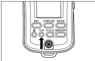
Hold down the POWER button for approx. 2 sec. while pressing the CLR button.
The power turns off and the default settings are restored. The shutter speed is set to 1/60 sec. Both the film speed and instant film speed are set to ISO 100. The measurement data and memory data are cleared.
Flat Diffuser
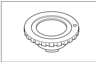
With this diffuser attached, the Flash Meter VI can be used to measure lighting contrast (ratio of brightness) and exposure for flat subjects.
Sync. Cord III
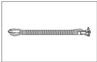
This is a 5-meter long cord that connects together the Flash Meter VI, flash unit and camera's sync terminal. Using this cord, you can take flash exposure readings by simply releasing the shutter, without changing any connections.
1. Care
1) If the meter gets dirty, it can be wiped with a soft, dry cloth. Do not use solvents such as thinners or benzene at all.
2) If the Spherical Diffuser becomes stained, remove it from the meter, wash the diffuser carefully in water with amild detergent, and rinse and dry the diffuser thoroughly before reattaching it to the meter.
3) Never attempt to disassemble the meter if it becomes damaged or faulty. Please contact a Minolta Service Facility.
2. Storage
1) The meter should not be stored in areas where it may be subject to temperatures higher than 55^ ( 131^ ) or lower than -20^ ( -4^ ), or in areas subject to high humidity. It is recommended that the meter be stored in an airtight container together with a drying agent such as silica gel.
2) Do not leave the meter in places such as the rear window or trunk of a car, otherwise it will get extremely hot, resulting in damage.
3) Remove the battery whenever the meter is left unused for more than 2 weeks, to avoid the risk of damage due to battery leakage.
Common accessories
| Item | Condition |
| 4X Spherical ND Diffuser | Set exposure correction to +2.0Ev. |
| 8X Spherical ND Diffuser | Set exposure correction to +3.0Ev. |
| Spot Mask | Nothing particular |
Only the accessories shown above may be used with the Flash Meter VI.
Handling Instructions
1) If the meter is used in the rain, at the seashore, or near a volcano, it may become rusty or corroded due to water or corrosive gas. In such situations, be careful to protect the meter as much as possible.
2) Do not subject the meter to shock or vibration. For protection, store the meter in its case when carrying it.
3) Be careful not to damage or soil the Spherical Diffuser; otherwise, the meter will not take accurate measurements.
4) Do not press on or damage the data panel.
5) Avoid using the meter under the following temperature conditions or under the following situations, since it is composed of precision electronic parts such as LSIs and LCD elements.
A) Do not use the meter in areas subject to temperatures higher than 50^ (122^) or lower than -10^ (14^) .
B) When the temperature of the meter falls below -10^ ( 14^ ), the display response becomes very slow and the display may become very difficult to read.
At temperatures between 0^(0^) and -10^ ( 14^ ), the display response is relatively slow, but there is no risk to the meter in such environments.
C) When the temperature of the meter rises above 50^ ( 122^ ), the display may become very difficult to read and the data panel will turn black.
If the meter is left under direct sunlight in the summer or near a heater, the temperature of the meter may get much hotter than the surroundings. So avoid this situation.
This instrument contains a microprocessor. If it is affected by electromagnetic interference or other influences, it may fail to function properly. If this happens, remove the battery and replace it. In such a case, remove and reinstall the battery. Turn on the power again, and reset the meter to the default settings (by holding down the POWER button while pressing the CLR button).
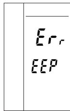
If the following error code appears, the calibration data have been damaged and the meter must be repaired.
After Service
1) Parts for repair of this product shall be available for at least seven years from the time of purchase.
2) For further details regarding After Service, please contact a Minolta Service Facility.
Specifications
| Type | Hand-held exposure meter for measuring ambient and flash light | |
| Reception method | Incident-light and spot reflected-light readings | |
| Receptors | Incident-light readings: Spherical Diffuser, Flat Diffuser, Swivels 270° Spot reflected-light: angle 1° | |
| Receptor element | Silicon photocell | |
| Measuring modes | AMBI mode: Ambient light CORD mode: Flash light using a sync cord NON CORD mode: Flash light without a sync cord (for incident-light reading only) | |
| Measuring range | (ISO100) Ambient light Incident-light readings: EV-2.0 to 19.9 Spot reflected-light: Ev2.0 to 24.5 Flash light Incident-light readings: FNO. 1.0 to 128+0.9 stop Spot reflected-light: FNO. 2.8 to 128+0.9 stop | |
| Measuring distance | 1.3 m to infinity (∞) (for spot measurement) | |
| Viewfinder | Single-lens reflect type with fixed focal point Magnification: 1.2x Viewing angle: 12° (vertical) x 17° (horizontal) Dioptric adjustment range: -3.0 to +1.0 | |
| Repeatability | ±0.1 EV | |
| Calibration coefficient | Incident-light readings: C=330 (Spherical Diffuser) C=250 (Flat Diffuser) Spot reflected-light: K=14 | |
| Display range | Exposure: F1.0 to 128+0.9 stop (0.1 stop increments) |
| EV: -17 to 40.9 (0.1 stop increments) | |
| Shutter speed (ambient): 30 min. to 1/16000 sec. (1, 1/2, 1/3 stop increments) | |
| Shutter speed (flash): 30 min. to 1/1000 sec. (1, 1/2, 1/3 stop increments) | |
| Frame rate (Opening angle of 180°): 8, 12, 16, 18, 24, 25, 30, 32, 64, 128 | |
| ISO: 3 to 8000 (1/3 increments) | |
| Exposure difference: -10 to +10 (0.1 stop increments) | |
| Analog scale: FNO. 1.0 to 90 (1/2 stop increments) | |
| Analyze scale: Flash light proportion 0 to 100% (25% increments) | |
| Other functions | Latitude display function, Light Ratio Analyze function, Memory function (10 measured values), S/A/H calculation, Brightness difference function, Exposure correction function: -10 to +10 (0.1 stop increments) |
| Others | Sync terminal |
| Power | One AA alkaline dry cell (LR-6/1.5 V) |
| Battery life | Approx. 30 hours: (Continuous operation for ambient light/incident light measurement, with alkaline dry cell) |
| Operating temperature/humidity | -10°C to 50°C (14°F to 122°F) |
| range | Relative humidity 85% max. [at 35°C (95°F)], no condensation |
| Storage | -20°C to 55°C (-4°F to 131°F) |
| temperature/humidity | Relative humidity 85% max. [at 35°C (95°F)], no condensation |
| range | no condensation |
| Dimensions | 63 (W) x 175 (H) x 30 (D) mm |
| Weight | 170 g (excluding battery) |
| Standard accessories | Spherical Diffuser, strap, case |
| *Optional accessories | Flat Diffuser, Sync. Cord III |
| ●Specifications and external appearances described herein are subject to change without notice. | |
MINOLTA
Minolta Co., Ltd.
3-13, 2-Chome, Azuchi-Machi, Chuo-ku, Osaka 541-8556, Japan
©2002 Minolta Co., Ltd.
ACMAPA(1) Printed in Japan
9222-8057-11
- Safety-related Icons
- SafetyWarnings and Cautions
- WARNING
- CAUTION
- STATEMENT OF FCC COMPLIANCE
- Table of Contents
- Names of Parts and Displays 2
- Preparations 9
- Basic Operation 19
- Special Functions 38
- 74
- Care and Storage 75
- Handling Instructions 76
- Specifications 78
- Names of Parts and Displays
- Data panel displays
- Analog scale status indicator
- Analog scale L
- Analog scale R
- Measurement data status indicator
- S/A/H indicator
- indicator
- Digital readout
- Shutter speed/framing-rate display
- Analyze scale
- Flash light measuring indicator
- Film speed display
- Measuring mode display
- Viewfinder display
- 13.Viewfinder indicator
- Viewfinder FNo./EV display
- Measuring index circle
- Preparations
- Battery
- Preparing
- Inserting
- Checking
- Setting film speed
- Setting instant film speed for test shooting
- Selecting a measuring method suitable for the light-receiving method
- Incident light measurement
- Attaching the Spherical Diffuser
- Removing the Spherical Diffuser
- Spot measurement
- Dioptric adjustment
- Difference between incident-light and Spot (reflected-light) readings
- Incident-light readings
- Spot (reflected-light) readings
- Basic Operation
- Select a measuring method
- Measuring ambient light
- With a still camera
- Display example
- Display units are FNo.
- Display units are EV
- With a cine camera
- Measuring flash light
- With a sync cord
- Without a sync cord (Incident light measurement)
- Light Ratio Analyze function
- How to read the flash/ambient light ratio
- Example of reading, display and simulation
- Special Functions
- Latitude display function
- Combining incident light measurement and spot measurement
- Memory function
- S/A/H (Shadow/Average/Highlight) calculations
- Average exposure
- Shadow calculations (for spot readings only)
- Highlight calculations (for spot readings only)
- Brightness difference function
- Measuring brightness difference relative to an exposure reading
- In AMBI mode
- In CORD mode
- Monitoring exposure difference after shadow-based exposure calculation
- AMBI mode
- CORD mode
- Measuring lighting ratio using the Flat Diffuser
- Using the Flash Meter VI as a simplified illuminance meter
- Using the Flash Meter VI as a simplified luminance meter
- How to read the EV-lx conversion table
- How to read the EV-cd/m² conversion table
- Custom settings mode (Alt mode)
- Selecting Alt mode
- 1) Exposure correction value
- 2) Shutter speed increments
- 3) Display unit
- FNo. 00o:
- FNo. 0.0:
- EV 00.o:
- 4) Latitude
- Reference: How to reset to initial settings
- Flat Diffuser
- Sync. Cord III
- Care
- Storage
- Handling Instructions
- After Service
- Specifications
- MINOLTA
- Minolta Co., Ltd.
Brand : MINOLTA
Model : FLASH METER VI
Category : Exposure and light measurement