
100L5ND - Projector HISENSE - Free user manual and instructions
Find the device manual for free 100L5ND HISENSE in PDF.
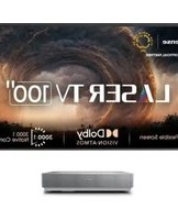


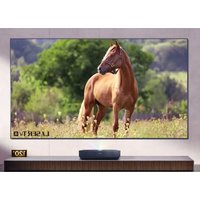
| Product Type | 4K Laser TV Projector |
| Brand | Hisense |
| Model | 100L5ND |
| Display Technology | DLP with Laser Phosphor |
| Resolution | 4K UHD (3840 x 2160) |
| Brightness | 3000 ANSI Lumens |
| Contrast Ratio | 100,000:1 |
| Throw Ratio | 0.25:1 (Ultra Short Throw) |
| Screen Size | 100 to 150 inches |
| Light Source | Laser |
| Lamp Life | Up to 20,000 hours |
| Power Consumption | 350W (Max) |
| Weight | 10.5 kg (23.1 lbs) |
| Dimensions (W x H x D) | 560 x 365 x 130 mm (22.0 x 14.4 x 5.1 in) |
| Video Inputs | HDMI 2.0 x 3, USB 2.0 x 2, RJ45 |
| Audio Outputs | 3.5mm Headphone Jack, Optical Out |
| Built-in Speakers | 30W (2 x 15W) |
| Smart TV Platform | VIDAA U4 |
| Wireless Connectivity | Wi-Fi 802.11ac, Bluetooth 5.0 |
| Mounting Options | Tabletop (feet adjustable) |
| Maintenance | Clean air filter every 3 months; wipe lens with soft cloth |
| Safety Features | Auto-off after 10 mins idle; laser eye-safe certification |
| Spare Parts Availability | Remote, power cord, air filter available from Hisense support |
| Repair Accessibility | Laser module replaceable by qualified technician |
Frequently Asked Questions - 100L5ND HISENSE
User questions about 100L5ND HISENSE
0 question about this device. Answer the ones you know or ask your own.
Ask a new question about this device
Download the instructions for your Projector in PDF format for free! Find your manual 100L5ND - HISENSE and take your electronic device back in hand. On this page are published all the documents necessary for the use of your device. 100L5ND by HISENSE.
USER MANUAL 100L5ND HISENSE
Read this guide carefully before installing the product and make sure you understand all the content.

Scan the QR code above for installation guide video.

Scan the QR code above for Multilingual QSGs.

Electric drill ∅6 & ∅8

Pencil

Philips screwdriver

Hammer

Stud finder
Level ruler
Hardware and Parts Lists
The appearance drawing in this manual is a schematic diagram. Please refer to the purchased actual product. After opening the package, please check the part list carefully. Due to product upgrading, the accessories are subject to change without prior notice.
| Code | Picture | QTY | Code | Picture | QTY |
| (A)The inner frame unit |  | 2 | (L) The connectors |  | 2 |
| (B) Vertical beam |  | 2 | *(M) M4X6 screw |  | 24 |
| (C) Short side pull rods |  | 2 | *(N) M4X16 screw |  | 18 |
| (D) Long side pull rods | 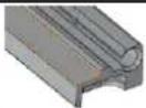 | 4 | (P) 150X20 Velcro |  | 2 |
| (E) Left long side outer frame pieces |  | 2 | (Q) The white protective sheet |  | 1 |
| (F) Right long side outer frame pieces |  | 2 | (V) Wall mount | 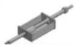 | 2 |
| (G) The short side outer frame pieces |  | 2 | (W) Adjusting rods |  | 2 |
| *(H) Inner frame connectors | 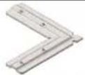 | 2 | (X) Connecting rods of hanging bracket |  | 2 |
| *(I) The connection bar |  | 2 | (Y) Gloves |  | 2 |
| (J1) Long side fiber rods |  | 4 | (Z1) Anchors and screws |  | 4 |
| *(J2) Short side fiber rods |  | 2 | (Z2) Plane nail |  | 4 |
| (K) Screen |  | 1 |
"*" Pre-installed or partial pre-installed
Read this guide carefully before installing this product and retain it for future reference.
Maintenance of Laser TV Screen
Use a dust-free soft cotton cloth dipped in absolute ethanol to gently wipe the screen and frame.
Warning
- Do not touch or wipe the screen directly with your hands or with an ordinary towel.
- Do not expose the screen to dripping or splashing.
- Do not place the screen on an unstable cart, tripod, or desktop. Dropping may cause serious damage and injuries.
- Do not scratch or touch the screen with hard or sharp objects.
- Do not expose the screen to direct sunlight.
- Do not place the screen near inflammable, explosive, or other dangerous objects.
- Disclaimer: All products, product specifications, and data are subject to change without notice to improve reliability, function, design, or other aspects.
Assembling the Screen
The installation procedure is divided into four parts: Assembling the inner frame, Assembling the screen, Assembling Outer Frame, Assembling Mounting Bracket. Find a spacious, flat, and clean place for installation.
Find a spacious, flat, and clean place for installation.
I. Assembling the inner frame
- Spread out the white protective sheet (Q) on the floor.
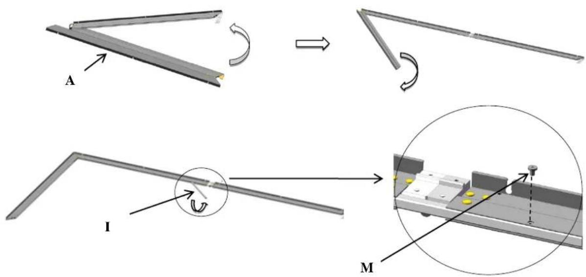
- Put on gloves (Y), assemble the inner frame unit (A).
- Assemble the inner frame unit (A) and vertical beam (B).
Note:
Remove the screws (M) (pre-installed) on the inner frame connectors (H) (pre-installed), insert the two inner frame connectors (H) in diagonal position, and then tighten the screws (M) to attach the inner frame connectors (H).

II. Assembling the screen
- Carefully unroll the screen (K) on the frame in the direction shown in the figure, then remove the protective cotton.
Note: Please pay attention not to scratch the screen and keep the side with "BOTTOM" upwards.
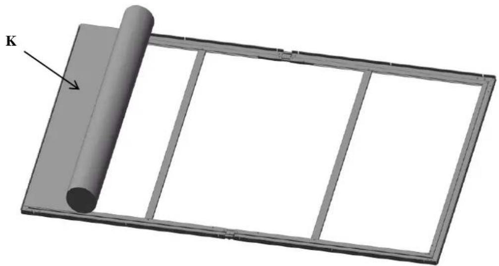
- Completely insert 4 fiber rods (J1) into the sleeves of the two long sides. Insert the fiber rod (J2) into the sleeves of the short sides, another fiber rod (J2) that has been pre-installed in the factory.

- Slide the edges of the screen into the grooves of the long side screen tension knobs (D) and the short side screen tension knobs (C).
- Adjust the position of the screen tension knob to fit the screen tension knob screw (N) (pre-installed) into the U-shaped groove of the frame.

- Tighten the screen tension knob screw (N) with 5.2lbf.in (6kgfcm) torque in the sequence of ①-① →②-②.

- Place the screen upright to check if the front screen surface is flat. If not, adjust the tension of the screen tension knob screw (N) as needed.
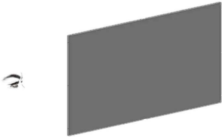
III. Assembling Outer Frame
- Rotate the screen, with the label "BOTTOM" facing up.
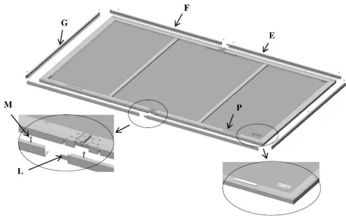
- Connect long side outer frame pieces (E and F) with the connectors (L), and fasten with screws (M).
- Fix the short sides outer frame pieces (G) with screws (M).
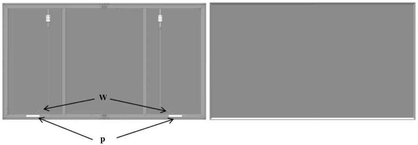
- Tear off the release film on one side of the Velcro (P) and attach them to the inner frame as shown in the illustration.
IV. Assembling Mounting Bracket
- Pinpoint the positions according to the distance measurements in the illustration below.
- There are three methods for installation, the first method (1) is used for solid wall, the second method (2) is used for drywalls or hollow walls (Thickness>0.39inch(10mm)), and the third method (3) is used for solid wood wall, only screws used.
- Drill holes on the wall with drill, insert the anchor (Z1 or Z2), and then attach the mounting brackets to the wall.
- Hang the connecting rods (X) on the mounting brackets, and then connect the adjusting rods (W) to the connecting rods.
- Only two holes should be used for each wall mount (V).
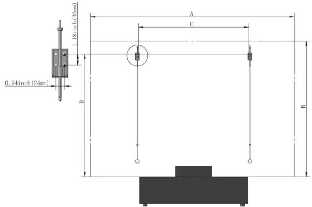
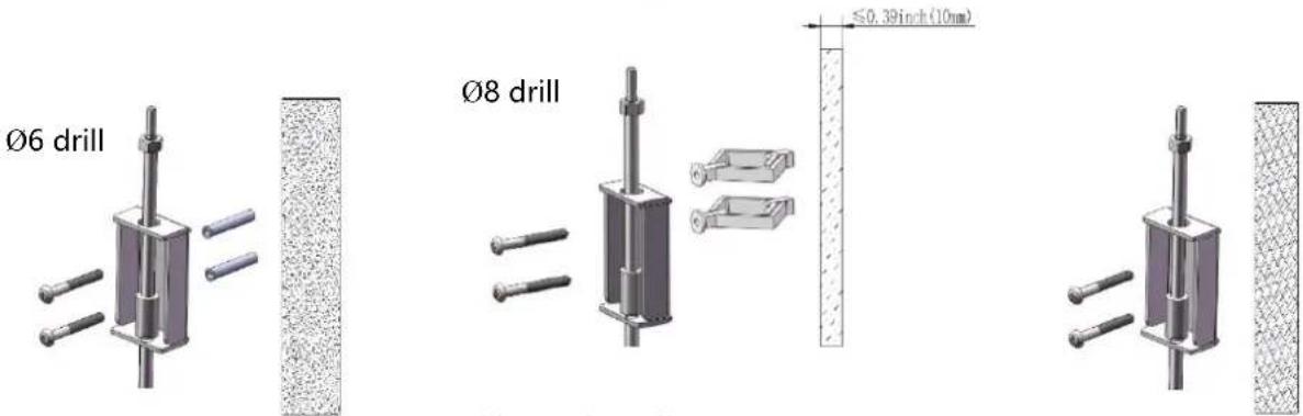
(1) For cement walls (2) For drywalls (3) For solid wood walls
| Model | A(space for installation) | B(space for installation) | C | D |
| L5H | W>90.6in.(W>2.3m) | H>66.9in.(H>1.7m) | 43.3±11.8in.(1100±300mm) | 58.9in.(1496mm) |
| L9H | W>90.6in.(W>2.3m) | H>66.9in.(H>1.7m) | 43.3±11.8in.(1100±300mm) | 59.8in.(1518mm) |
- Hang the screen on the hanging brackets and check if it is horizontally straight. If not, twist adjusting rods (W) as needed.
Note: Make sure the "BOTTOM" label is at the bottom of the screen and facing the wall.

| Model | L | H |
| L5H | 12.9in.(327mm) | 13.8in.(351mm) |
| L9H | 11.9in.(303mm) | 14.7in.(373mm) |
Note: ±5% deviation is acceptable for L and H.
- Fold and hide the adjusting rods (W) on the screen bracket on the bottom of the screen.
Note:
After the screen is mounted, tear off the release film on the other side of the Velcro (P) to attach the screen to the wall.
Tear off the protective tape on the four corners of the screen.

Brand : HISENSE
Model : 100L5ND
Category : Projector