
565i - Pump Testo - Free user manual and instructions
Find the device manual for free 565i Testo in PDF.


| Product Type | Leak Detection Pump |
| Brand | Testo |
| Model | 565i |
| Dimensions (L x W x H) | 210 x 50 x 50 mm |
| Weight | 350 g |
| Power Supply | 2x AA batteries (not included) |
| Battery Life | Approx. 20 hours continuous use |
| Flow Rate | 0.5 L/min |
| Max Pressure | 0.5 bar |
| Sensor Type | Semiconductor |
| Refrigerants Detected | R-22, R-134a, R-404A, R-410A, and others |
| Display | None (visual/audible alarm) |
| Alarm | Audible and visual LED |
| Warm-Up Time | Approx. 30 seconds |
| Operating Temperature | 0 to 40 °C |
| Storage Temperature | -20 to 60 °C |
| Maintenance | Clean with a soft, dry cloth; replace sensor filter annually |
| Safety Precautions | Do not use near flammable gases; replace batteries in low-battery condition |
| Spare Parts | Replacement filter (0554 3286), sensor tip |
| General Information | Handheld leak detector for HVAC/R systems |
Frequently Asked Questions - 565i Testo
User questions about 565i Testo
0 question about this device. Answer the ones you know or ask your own.
Ask a new question about this device
Download the instructions for your Pump in PDF format for free! Find your manual 565i - Testo and take your electronic device back in hand. On this page are published all the documents necessary for the use of your device. 565i by Testo.
USER MANUAL 565i Testo
testo 565i Vacuum Pump
Instruction manual

Contents
1 About this document ....3
2 Safety and disposal....4
2.1 Product-specific information 4
2.2 Disposal 7
3 Intended use....7
4 Product description ....8
4.1 Overview 8
5 First steps....10
5.1 Switching the instrument on and off 10
5.2 Evacuation with a manifold....12
5.3 Direct Evacuation....16
6 Maintenance....21
6.1 Cleaning instruments....21
6.2 Keeping connections clean 21
6.3 Choosing correct pump oil....21
6.4 Changing pump oil 22
6.5 Replacing oil mist trap....22
7 Technical data 23
7.1 Version 7 CFM 23
7.2 Version 10 CFM 24
8 Tips and assistance ....24
8.1 Accessories....24
9 Support 25
9.1 Trouble shooting....25
9.2 Error codes....26
1 About this document
- The instruction manual is an integral part of the instrument.
- Pay particular attention to the safety instructions and warning advice in order to prevent injury and damage to the product.
- Please read this instruction manual through carefully and familiarize yourself with the product before putting it to use.
Symbols and writing standards
| Display | Explanation |
 | Note: basic or further information |
 | Warning advice, risk level according to the signal word:Warning! Serious physical injury may occur.Caution! Minor physical injury or damage to the equipment may occur.Careful! Possible damage to equipment.- Implement the specified precautionary measures. |
| 12... | Action: several steps, the sequence must be followed |
| Result of an action | |
| √ | Requirement |
| Menu | Elements of the instrument, the instrument display or the program interface. |
| [OK] | Control keys of the instrument or buttons of the program interface. |
2 Safety and disposal
General safety instructions
- Always operate the product properly, for its intended purpose and within the parameters specified in the technical data. Do not use any force.
- Do not commission the instrument if there are signs of damage on the housing.
- Dangers may also arise from the systems being measured or the measuring environment: Make sure you comply with the locally valid safety regulations when carrying out measurements.
- Do not expose the product to temperatures above 50 °C (122 °F).
- Do not store the product together with solvents. Do not use any desiccants.
- Only maintenance and repair work that is described in the documentation may be carried out on this instrument. Follow the prescribed steps exactly when doing the work. Only use original spare parts from Testo.
2.1 Product-specific information
To prevent personal injury, please read the operating manual carefully.
- The testo 565i vacuum pump may only be used by qualified personnel with the appropriate qualifications and in accordance with local regulations.
- Wear goggles when working with refrigerants.
- Do not touch refrigerants without protection.
- To avoid electrical shock, confirm that all associated devices are grounded correctly before connecting the power.
- Do not touch the pump housing or motor during operation.
- When pumping R32/1234yf, please use explosion-proof socket.
- Do not use on pressurized systems.
- Do not use to extract refrigerants. Before evacuation, the refrigerant must be removed from the system using a suction station.
- If not used, close connections to protect against contamination.
- Do not use with ammonia.
- Use with A2L / A3 refrigerants
The testo 565i vacuum pump can be used in compliance with the prescribed laws, standards, directives and safety regulations for refrigeration systems and refrigerants as well as regulations of the manufacturers of refrigerants of safety group A2L / A3 as per ISO 817.
Regional standardization and interpretation must always be observed.
For example, DIN EN 378-Part 1-4 applies to the scope of the EN standards.
During maintenance work, the employer must ensure that a hazardous explosive atmosphere is prevented (see also TRBS1112, TRBS2152 VDMA 24020-3).
A hazardous and potentially explosive atmosphere must be anticipated during maintenance and repair work on refrigeration systems with flammable refrigerants (e.g. those in category A2L and A3).
Maintenance, repairs, removal of refrigerants and commissioning of systems may only be carried out by qualified personnel.
Before operating
- Check the voltage and frequency matching the specifications on the pump motor nameplate.
- Ensure that the ON-OFF switch is in the OFF position before connecting the pump to a power source.
- All motors are designed for operating voltages plus or minus 10% of the normal rating. Power socket must be grounded.
- Before connect to A/C-R system, please pump the refrigerants with reliable way from the system with the help of a suction station.
- If the supply is damaged pull the plug from the mains before examining.
- If the supply cord is damaged, it must be replaced by the manufacturer, its service agent or similarly qualified persons in order to avoid a hazard.
- Do not use an extension cord.
Grounding instructions
- This product must be grounded. In the event of an electrical short circuit, grounding reduces the risk of electric shock by providing an escape wire for the electric current. This product is equipped with a cord having a grounding wire with an appropriate grounding plug. The plug must be plugged into an outlet that is properly installed and grounded in accordance with all local codes and ordinances.
WARNING
For model 0564 6562 01 and 0564 6563 01: This product is for use on a nominal 120 V circuit and has a grounding plug similar to the plug illustrated in sketch A in the figure below.
Only connect the product to an outlet having the same configuration as the plug. Do not use an adapter with this product.

WARNING
Risk of electric shock due to Improper installation of the grounding plug.
- When repair or replacement of the cord or plug is required, do not connect the grounding wire to either flat blade terminal.
- The wire with insulation having an outer surface that is green with or without yellow stripes is the grounding wire.
- Check with a qualified electrician or serviceman when the grounding instructions are not completely understood, or when in doubt as to whether the product is properly grounded. Do not modify the plug provided; if it does not fit the outlet, have the proper outlet installed by a qualified electrician.
Oilfilling
- Remove the oil fill cap and add oil until oil level showed in the middle between the Min and Max mark. Please refer to technical data in manual for the correct oil capacity.
CAUTION
Danger of oil spillage in case of fast filling.
- Fill in the oil slowly.
During operation
CAUTION
Risk of electric shock.
- Do not expose to rain and store indoors.
- As long as the vacuum pump is not connected to the refrigeration circuit, it should not be running more than 3 minutes.
- The ambient temperature affects the viscosity of the oil and therefore also the pump performance. Therefore the pump should be operated only at ambient temperature between 5-40°C.
- It is recommended to pre-flush the system with nitrogen to speed up the drying process. This step can also be repeated during evacuation to ensure the best possible drying.
- The use of shorter hoses or the removal of the Schrader valve can significantly speed up evacuation.
- Use vacuum-compatible refrigerant hoses, otherwise leaks may occur or you may not achieve the desired vacuum target.
- To prevent overheat and oil spill out from oil filter: The inlet fitting can't expose to the atmosphere over 5 minutes while the pump is running.
- Please pay attention to the smooth air outlet, if found clogged please clean the filter.
- Clean/replace the catcher after using more than 3 months to avoid problems caused by a blocked pump.
2.2 Disposal
- At the end of its useful life, deliver the product to the separate collection point for electric and electronic devices (observe local regulations) or return the product to Testo for disposal.
- WEEE Reg. No. DE 75334352
3 Intended use
The testo 565i vacuum pumps is intended to be used in the refrigeration service including CFC, HCFC, and HFC refrigerants (such as
R12/R22/R23/R32/R134A/1234yf and so on), Printing Industry vacuum packaging, Gas Analysis, Thermo Forming industry and so on. It can also be applied as the pre-pump of various types of high vacuum equipment.
The testo 565i vacuum pump should only be used for evacuation of refrigerant systems after refrigerant has been removed from the system and the system has been opened to atmosphere. It is not to be used as a transfer pump for liquids or any other media; doing so can damage the product.
The testo 565i vacuum pump complies to the standard 61000-6-4 and 61000-6-2 for EMC. Accordingly the intended use is in industrial environment only.
The testo 565i vacuum pump must not be used by children and persons with reduced physical, sensory or mental capabilities or lack of experience and knowledge unless they have been given supervision or instruction concerning use of the appliance in a safe way and understand the hazards involved.
Children shall not play with the device.
4 Product description
4.1 Overview
| 1 | Power switch | 2 | Nameplate |
| 3 | Handle | 4 | Inlet fitting |
| 5 | Oil fill cap | 6 | Exhaust fitting |
| 7 | Oil housing | 8 | Sight glass |
| 9 | Oil drain plug | 10 | Base |
| 11 | Motor | 12 | Fan cover |
Symbol explanation
 | Observe operating instructions |
 | ATTENTION |
| Magnetic fieldDamage to other devices!Keep a safe distance from products that can be damaged by magnetism (e.g. monitors, computers, credit cards). | |
 | WARNING |
| Magnetic fieldMay be hazardous to the health of pacemaker wearers.Keep a minimum distance of 15 cm between the pacemaker and the device. | |
 | WARNING |
| Risk of burns from hot surfacesDo not touch the pump housing or motor during operation.Allow it to cool down first after operation. | |
 | Hearing protection must be worn |
 | Do not use in rain or wet conditions |
 | If cable is damaged, pull the plug from the mains before examining. |
5 First steps
5.1 Switching the instrument on and off
Before operation
1 Check the voltage and frequency matching the specifications on the pump motor nameplate.
2 Ensure that the ON-OFF switch is in the OFF position before connecting the pump to a power source.
3 Remove the Oil Fill Gap and add oil until oil level showed in the middle between the "Min" and "Max" mark. Refer to chapter "Technical data" for the correct oil capacity.
CAUTION
Danger of oil spillage in case of fast filling.
- Fill in the oil slowly.
Switching on testo 565i
1 Turn the motor switch to ON position.
This may takes 2 to 30 seconds depend on the ambient temperature.
2 After the pump operates for approximately one minute, check the sight glass for proper oil level, which should always be visible in the middle between Max and Min mark

Refill oil if necessary.
3 Place back the cap on the inlet fitting when the pump runs smoothly.

The oil level should always be visible in the middle between Max and Min mark when the pump is running. Insufficient oil filled will result in poor vacuum performance. Excessive of oil can result in overflowing of oil from the exhaust fitting.
Connecting refrigerant container
1 First remove one of the protection caps (please refer the right figure) and then connect the container via hose.
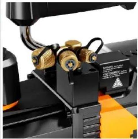
2 Check the tightness of the inlet connector.
3 Turn off the valve between pump and container.
4 Turn off the power.
5 Remove the hose.
6 Screw the protection cap to avoid the granule into the pump.
5.2 Evacuation with a manifold
1
Connect the manifold and testo 565i to the refrigeration circuit.
![graph TD A["Air Conditioner"] -->|Bluetooth| B["testor 552i"] A -->|Bluetooth| C["testo 565i"] B -->|Bluetooth| C D["Testor 552i"] -->|Bluetooth| C E["Testor 565i"] -->|Bluetooth| C F["Device Image"] --> G["Line Chart"] H["User Interface"] --> I["Control buttons"]](/content/2026/07/1436202/images/7bd33285de93fab0ee60905c82fa7474ddb584fde2da95c3c92c47aeb9902f42.jpg)
2
Connect testo 552i with the manifold.
3
Establish a Bluetooth connection between testo 552i and testo 565i.
4
Establish a Bluetooth connection between manifold and testo Smart App.

All configurations are done via the manifold. The testo Smart App is operating in second screen mode. All measurement values from the installation aid are mirrored in the testo Smart App.
5 Enter the desired vacuum target values in the manifold and activate Auto Re-Start function if required (value higher than 0).

Auto Re-Start function:
Once the target value has been reached, the pump is reactivated and the vacuum hold test is performed. The auto restart is repeated according to the input.

6 Start evacuation with Start. The pump starts automatically and the measurement begins.

The measurement is running, the vacuum holding test has not yet started.

When the target values are reached, the evacuation and therefore also the pump are stopped automatically. The vacuum hold test begins.
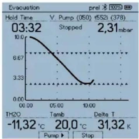
If the Auto Re-Start function has been activated, evacuation is restarted in order to restart the vacuum hold test once the target value has been reached.
The vacuum hold test can be ended via Stop.

The measurement data is transferred to the testo Smart App and evaluated there.
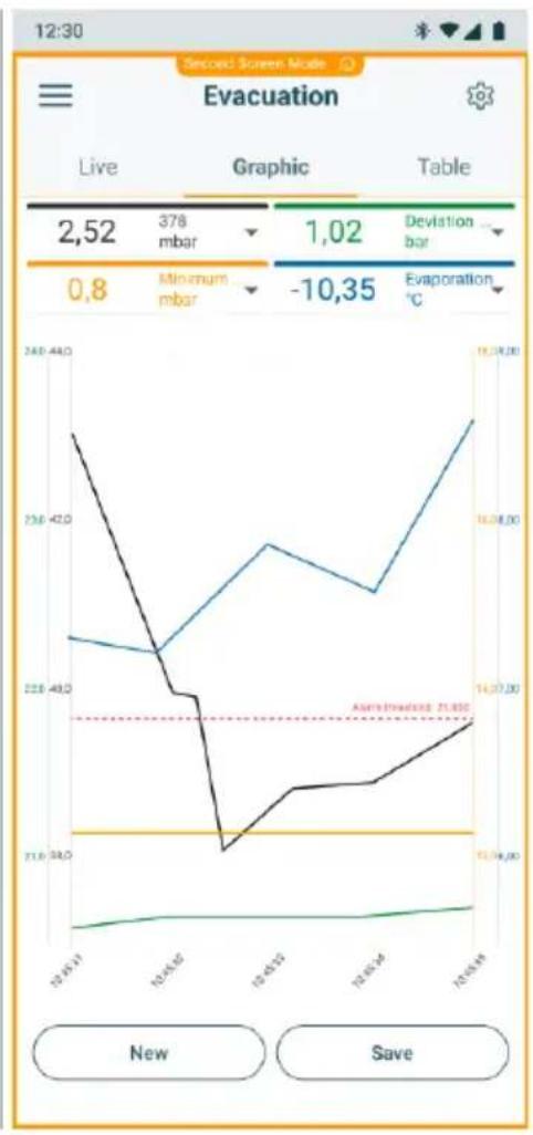
5.3 Direct Evacuation
1
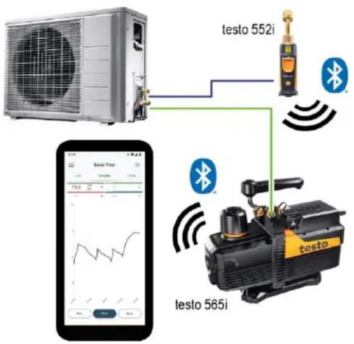
Connect testo 565i and testo 552i to the refrigeration circuit.
2
Establish a Bluetooth connection between testo 552i and testo 565i.
3
Establish a Bluetooth connection between testo 565i and testo Smart App.
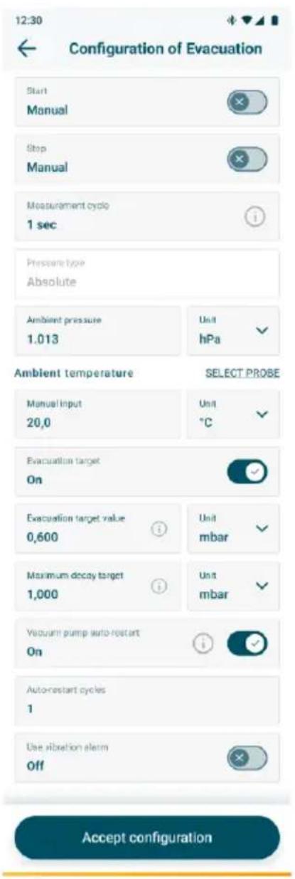
4 Enter the desired vacuum target values in the testo Smart App.
Activate/deactivate the Auto Re-Start function to repeat the evacuation and vacuum hold test after the target value has been reached. By entering the maximum number of repetitions, you determine the number of automatic evacuations/vacuum hold tests.

Auto Re-Start function:
Once the target value has been reached, the pump is reactivated and the vacuum hold test is performed. The auto restart is repeated according to the input.
5
Start evacuation with Start.
The pump starts automatically and the measurement begins.

▶
The measurement is running, the vacuum holding test has not yet started.
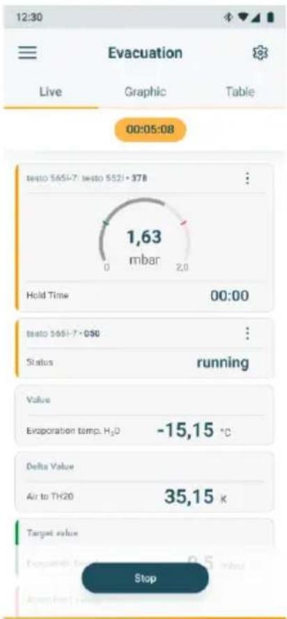
When the target values are reached, the evacuation and therefore also the pump are stopped automatically. The vacuum hold test begins. The vacuum hold test can be ended via Stop.

If the Auto Re-Start function has been activated, evacuation is restarted in order to restart the vacuum hold test once the target value has been reached.
The measurement data is transferred to the testo Smart App and evaluated there.

6 Maintenance
6.1 Cleaning instruments

Do not use any aggressive cleaning agents or solvents! Mild household cleaning agents and soap suds may be used.
If the instrument housing is dirty, clean it with a damp cloth.
6.2 Keeping connections clean
Keep screw connections clean and free of grease and other deposits; clean with a damp cloth as required.
6.3 Choosing correct pump oil
The condition and type of oil used in any high performance vacuum pump are extremely important in determining the ultimate attainable vacuum. It is recommended to use High Performance Vacuum Pump Oil (Recommended viscosity of 46 mm²/s at +40°C), which is specifically blended to maintain maximum viscosity at normal running temperatures and to improve cold weather start up.
ATTENTION
Risk of damage
Change the pump oil timely when oil was contaminated or emulsified.
6.4 Changing pump oil
1 Ensure the pump is warmed up.
2 Remove the oil drain plug.
3 Drain off contaminated oil into a container and dispose it properly.
Oil can be removed from the pump by opening the inlet and partially blocking the exhaust with a cloth while the pump is running.
4 When the drainage of oil completed, tilt the pump forward to remove the residual oil.
5 Place back the oil drain plug.
6 Remove the oil fill cap and fill the oil reservoir with new vacuum pump oil until oil level is seen in the middle between "Max" and "Min" mark.
7 Close the oil fill cap.
6.5 Replacing oil mist trap

If the performance of the pump has decreased seriously, please replace the oil mist trap.
The oil mist trap can only be replaced as a single part, not to each individual part.
1 Turn the oil mist trap counterclockwise until it is completely screwed out.
2 Replace with a new oil mist trap and slowly screw it in clockwise until the bottom plane of the base is almost in contact with the oil tank.
It cannot be violently screwed in if the threads are not aligned, otherwise it could cause damage to the base threads.
7 Technical data
7.1 Version 7 CFM
| Feature | Value | |
| Model no. | 0564 5652 01 | 0564 5652 |
| Voltage | 120 V~ / 60 Hz | 230 V~ / 50 Hz |
| Rated current | 3.3 A | 1.9 A |
| Max. current | 8.5 A | 4.8 A |
| Power | 805 W | 800 W |
| Storage and transport temperature | -10 ... +50 °C / +14 ... +122 °F | |
| Operating temperature | +5 ... +40 °C / +41 ... 104 °F | |
| Flow rate | 198 l/min / 7 CFM | |
| Ultimate Vacuum | 15 micron | |
| Max. oil capacity | 610 ml / 20.6 fl. oz. | |
| Dimension | 375 x 150 x 314 mm / 14.8 x 5.9 x 12.4 in | |
| Weight | 11.3 kg / 24.9 lb | |
| Intake Ports | 1/4" & 3/8" & 1/2" SAE | |
| Noise tested acc. to EN ISO 2151:2008 as following: | ||
| Sound pressure level at working station | 65.03 dB(A), K = 3 dB(A) | |
| Sound power level | 74.19 dB(A), K = 3 dB(A) | |
7.2 Version 10 CFM
| Feature | Value | |
| Model no. | 0564 5653 01 | 0564 5653 |
| Voltage | 120 V~ / 60 Hz | 230 V~ / 50 Hz |
| Rated current | 3,3 A | 1,9 A |
| Max. current | 10,1 A | 5,5 A |
| Power | 950 W | 940 W |
| Storage and transport temperature | -10 ... +50 °C / +14 ... +122 °F | |
| Operating temperature | +5 ... +40 °C / +41 ... 104 °F | |
| Flow rate | 283 l/min / 10 CFM | |
| Ultimate Vacuum | 15 micron | |
| Max. oil capacity | 545 ml / 18.4 fl. oz. | |
| Dimension | 375 x 150 x 314 mm / 14.8 x 5.9 x 12.4 in | |
| Weight | 12.1 kg / 26,7 lb | |
| Intake Ports | 1/4" & 3/8" & 1/2" SAE | |
| Noise tested acc. to EN ISO 2151:2008 as following: | ||
| Sound pressure level at working station | 67.13 dB(A), K = 3 dB(A) | |
| Sound power level | 76.29 dB(A), K = 3 dB(A) | |
8 Tips and assistance
8.1 Accessories
| Description | Order no. |
| testo 552i – App-controlled wireless vacuum probe | 0564 2552 |
| Vacuum pump oil 330 ml | 0564 1002 |
For a complete list of all accessories and spare parts, please refer to the product catalogues and brochures or visit our website www.testo.com.
9 Support
You can find up-to-date information on products, downloads and links to contact addresses for support queries on the testo website at: www.testo.com.
9.1 Trouble shooting
| Problem | Possible reason | Actions |
| Fail to attain good vacuum | - Spare intake port cap loosen- O ring inside the spare intake port cap damaged- Insufficient oil- Pump oil emulsification or pump oil dirty- Oil inlet channel is clogged or insufficient oil- Pumping system in leaking- Not suitable pump- Pump spare parts are worn out after long use | - Fasten the intake port cap- Change the O ring- Add oil- change oil- Clean the oil inlet channel. dean the filter screen- Check the pumping system, no leakage- Chose the right pump- Repair the pump or replace the pump if necessary. |
| Oil leakage | - Oil seal damage- Oil housing assy. Connections loosen or damage. | - Change oil seal- Fasten the screw and change the O-ring in the oil housing assy. |
| Oil injection | - Excessive oil in the pump- Continuous operation under high pressure in the inlet port | - Drain oil- Chose the right pump |
| Hard to start | - Oil temperature is too low- Malfunction of motor or power supply- Foreign matters entered into the pump chamber- The voltage is too low or too high- Over load protection | - Start the pump repeatedly and remove the oil filter- Check and repair- Check and clean the pump- Check the operating voltage- Keep the power switch on, remove the plug and wait 30 seconds. find the reason of over load protection, then re- run the pump. |
9.2 Error codes
| Code | Error | Description |
| E76 | Error in vacuum pump motor | The vacuum pump testo 565i has stopped evacuation because an error has occurred. Please restart the vacuum pump. If the error continues to occur, please contact Testo Service. |
| E77 | Vacuum pump overheats | The vacuum pump testo 565i has stopped evacuation because the motor overheated. As soon as the motor has cooled down, you can restart the evacuation via the vacuum pump. |
| E78 | Temperature sensor in pump failed | The vacuum pump testo 565i has stopped evacuation because the internal temperature sensor has implausible values. Please contact Testo Service to replace the sensor. |
| E79 | Impermissible operating voltage | The vacuum pump testo 565i has stopped evacuation because the operating voltage is outside the range. Please check the power supply. |
| E80 | Motor does not work | The vacuum pump testo 565i has stopped evacuation because the motor can't start. Please disconnect and try again. |
| E81 | Battery no longer charged | The internal battery of the digital manifold is no longer being charged because the ambient temperature is too high. The charging process is resumed as soon as the temperature has dropped. |
| E84 | Communication error | An error has occurred in the vacuum pump testo 565i. The pump is currently not working. Please contact Testo Service for repair. |
| E85 | Error in vacuum pump motor | The vacuum pump testo 565i has stopped evacuation because an error has occurred. Please restart the vacuum pump. If the error continues to occur, please contact Testo Service. |
| E86 | Error | An error has occurred. Please contact Testo Service. |
| E88 | Error | An error has occurred. Please contact Testo Service. |
| E89 | Smart Probe testo 552i is not available | testo 552i has lost the Bluetooth connection to testo 565i.1. please restart testo 552i and ensure that it is connected to the pump.2. please check whether the testo 552i has sufficient battery capacity. If not, please replace the batteries. |
If you have any questions please contact your local dealer or the Testo Customer Service. You can find contact details on the back of this document or online at www.testo.com/service-contact.
Testo SE & Co. KGaA
Celciusstrasse 2
79822 Titisee-Neustadt
Germany
Phone: +49 (0)7653 681-0
E-mail: info@testo.de
Internet: www.testo.com
- TESTO 565I VACUUM PUMP
- CONTENTS
- 1 ABOUT THIS DOCUMENT
- 2 SAFETY AND DISPOSAL
- GENERAL SAFETY INSTRUCTIONS
- 2.1 PRODUCT-SPECIFIC INFORMATION
- BEFORE OPERATING
- GROUNDING INSTRUCTIONS
- WARNING
- OILFILLING
- CAUTION
- DURING OPERATION
- 2.2 DISPOSAL
- 3 INTENDED USE
- 4 PRODUCT DESCRIPTION
- 4.1 OVERVIEW
- 5 FIRST STEPS
- 5.1 SWITCHING THE INSTRUMENT ON AND OFF
- BEFORE OPERATION
- SWITCHING ON TESTO 565I
- CONNECTING REFRIGERANT CONTAINER
- 5.2 EVACUATION WITH A MANIFOLD
- 5.3 DIRECT EVACUATION
- AUTO RE-START FUNCTION
- 6 MAINTENANCE
- 6.1 CLEANING INSTRUMENTS
- 6.2 KEEPING CONNECTIONS CLEAN
- 6.3 CHOOSING CORRECT PUMP OIL
- ATTENTION
- 6.4 CHANGING PUMP OIL
- 6.5 REPLACING OIL MIST TRAP
- 7 TECHNICAL DATA
- 7.1 VERSION 7 CFM
- 7.2 VERSION 10 CFM
- 8 TIPS AND ASSISTANCE
- 8.1 ACCESSORIES
- 9 SUPPORT
- 9.2 ERROR CODES
Brand : Testo
Model : 565i
Category : Pump