MagicDMX Basic - DMX Interface ChamSys - Free user manual and instructions
Find the device manual for free MagicDMX Basic ChamSys in PDF.


| Product Type | DMX USB Interface |
| Brand | ChamSys |
| Model | MagicDMX Basic |
| DMX Output | 1 universe (512 channels) |
| Connection | USB 2.0 |
| DMX Connector | 5-pin XLR female |
| Power Supply | USB bus-powered (5V) |
| Current Consumption | 100 mA |
| Dimensions (L x W x H) | 70 x 40 x 20 mm |
| Weight | 80 g |
| Compatible Software | ChamSys MagicQ (PC/Mac) |
| Operating System | Windows, macOS |
| DMX Protocol | DMX512-A |
| Galvanic Isolation | Yes (typically) |
| Main Functions | Control lighting fixtures via DMX; show recording/playback |
| Maintenance | Keep dry; clean with soft dry cloth |
| Safety | Low voltage device; no hazardous materials |
| Repairability | Not user-serviceable; contact support |
| Spare Parts | None available; replace unit if defective |
| Warranty | 2 years (check local terms) |
Frequently Asked Questions - MagicDMX Basic ChamSys
User questions about MagicDMX Basic ChamSys
0 question about this device. Answer the ones you know or ask your own.
Ask a new question about this device
Download the instructions for your DMX Interface in PDF format for free! Find your manual MagicDMX Basic - ChamSys and take your electronic device back in hand. On this page are published all the documents necessary for the use of your device. MagicDMX Basic by ChamSys.
USER MANUAL MagicDMX Basic ChamSys
1.1 MagicQ software and consoles 2 1.2 MagicQ MQ500 Stadium Console 2 1.3 MagicQ Compact Series 3 1.4 MagicQ Wings for use with PC/Mac 3 1.5 Plugging Up 4 1.6 DMX Connections 4 1.7 Powering Up 4 1.8 Powering Down 4 1.9 Resetting the Console 5 1.10 Hard Reset 5 1.11 Power Supply Protection 5 1.12 Care of your MagicQ console 5 1.13 Safety Information 6 1.14 Security Information 6 1.15 Disposal Information 6
2 Installing MagicQ Software & Drivers 7
2.1 MagicQ software 7 2.2 MagicDMX 7 2.3 MagicQ Wings & Interfaces 7
2.3.1 GeNetix nodes 8
2.4 MagicQ on Windows 8
2.4.1 Drivers for older MagicQ products 8 2.4.2 User permissions on Windows 15
2.5 MagicQ on Mac 15
2.5.1 Turning off App Nap 15 2.5.2 Making the MagicQ folder writeable 16
2.6 MagicQ on Linux 17
2.6.1 Installing 17 2.6.2 High DPI screens 17
3 Using MagicQ on PCs and Macs 19
3.1 Simple Generic Console 19 3.2 Technician Test Head 20 3.3 Demo Shows 21 3.4 Touch View 22 3.5 Playback mode 22 3.6 Copy and paste to external applications via the clipboard 22 3.7 MagicQ PC / Mac Restrictions (Demo Mode and Core Mode) 23
3.7.1 DEMO MODE 23 3.7.2 CORE MODE 23 3.7.3 UNLOCKED MODE 24 3.7.4 GeNetix / SnakeSys DMX Node Unlocking 24 3.7.5 MagicHD Stand Alone Restriction 25
4 MagicQ Concepts 26
4.1 Show Storage 26 4.2 Output channels 26
4.2.1 HTP / LTP channels 27
4.3 Cues 27 4.4 Cue Stacks 28 4.5 Playbacks 28 4.6 Pages 28 4.7 FX 28 4.8 Window Layouts 29 4.9 Shift Functions 29 4.10 The Programmer 29 4.11 Help 29
5 MagicQ Layout 30
5.1 Physical layout 30
5.1.1 Touch Screen, Encoders & Soft Buttons 30 5.1.2 Main Windows 31 5.1.3 Layouts 32 5.1.4 Active Window 32 5.1.5 Window Sizing 33 5.1.6 Support for Find in MagicQ windows 33 5.1.7 Support for Cut and Paste in MagicQ windows 33 5.1.8 Status and Display Windows 34 5.1.9 Head Control 34
5.1.10 Editor Buttons 35 5.1.11 Playback 35
5.2 Keyboard, Keypad, Select & Confirm Windows 36
5.3 Common Actions 36
5.3.1 Items 36 5.3.2 Setting the value of items 37 5.3.3 Naming items 37 5.3.4 Moving items 37 5.3.5 Copying items 38 5.3.6 Removing items 38 5.3.7 Recording items 38
5.4 Icons 38
5.4.1 Custom Photo Icons 38 5.4.2 Actions on Playbacks 39
6 Quick Start 40
6.1 Starting up MagicQ 40 6.2 Calibrating the Touch Screen 40 6.3 Starting a New Show 41 6.4 Enabling Outputs 42
6.4.1 Using Direct DMX Outputs 42 6.4.2 Using Outputs via network 42
6.5 Connecting a MagicQ Playback Wing 43 6.5.1 Setting Playback Wing IDs 43 6.6 Connecting External Monitors 43 6.7 Patching 44
6.7.1 Naming and Numbering Fixtures 45
6.8 Controlling Heads 46
6.8.1 Selecting Heads 46 6.8.2 Selecting heads from the Group/Heads Window 46 6.8.3 Recording a Group 47
6.9 Naming a Group 47
6.10 Recalling a Group 47 6.11 Setting Levels for Dimmers 47 6.12 Locating Heads 48 6.13 Modifying Attributes 48 6.14 Recording a Palette 50 6.15 Adding in FX 51 6.16 Recording a Cue 51 6.17 Recording a Cue Stack (Chase or Theatre Stack) 51 6.18 Selecting and recording complete window layouts 52 6.19 Saving the Show 52 6.20 Playback 53
7 Patching 54
7.1 Patching on MagicQ 54 7.2 Getting started with patching 54 7.3 Patching a Head or Dimmer 54 7.4 Head Names and Head Numbers 56
7.4.1 Head Names 56 7.4.2 Head Numbers 57 7.4.3 Renumbering Head Numbers 57 7.4.4 Patching to specific Head numbers 57
7.5 Gel name and number 57 7.6 Col Tags 57 7.7 Generating auto groups 58 7.8 Auto Palettes 58 7.9 Heads with multiple elements 58
7.9.1 Duplicated Heads 58 7.9.2 Multi Element Heads 59
7.10 Inverting and Swapping 59 7.11 Pan and Tilt Offsets 59 7.12 Applying Offsets using Update 59 7.13 Minimum and Maximum levels 60
7.13.1 Limits and Offset. 60
7.14 Dimmer curves 60 7.15 Testing channels 61 7.16 Changing the DMX address of heads 61 7.17 Patching a Head to multiple DMX addresses 62 7.18 Unpatching a Head from a DMX address 62 7.19 Patching scrollers 62 7.20 Editing Heads 62
7.21 Cloning (Adding extra heads / dimmers to a programmed show) 63
7.21.1 Copy Head Programming 63 7.21.2 Patch Channel Copy 63
7.22 Morphing Heads (Changing Head type) 64
7.22.1 Morphing multi element heads 64 7.22.2 Morphing Heads with virtual dimmers 64 7.22.3 Morphing between CMY and colour wheel Heads 64
7.23 Importing Heads 65
7.23.1 Supported column headings 65 7.23.2 WYSIWYG 66 7.23.3 VectorWorks 66
7.23.4 Depence 68 7.23.5 Creating a head list 68
7.24 Exporting Heads 68 7.25 VL5 type channels (split personalities) 68 7.26 Merging with DMX input 69 7.27 Customising Locate, Default, Highlight and Lowlight values 69 7.28 Theatre Patch syntax 70 7.29 Virtual Dimmers 70
7.29.1 Quickly adding Virtual Dimmers to patched heads 70 7.29.2 Heads always with virtual dimmers 71
7.30 Patch Head Filtering 71
7.30.1 Duplicated elements operating independently 71
8 Setting Intensity levels 73
8.1 Using the on screen faders 73 8.2 Using the encoders 74 8.3 Using the keypad 74
8.3.1 Setting fade times from the keypad 74
8.4 Setting intensity FX from the keypad 75 8.5 Multi Element Heads 75 8.6 Setting intensity levels for DMX channels 75 8.7 Using Selected Heads 75 8.8 Using gel colours in the Intensity Window 76
8.8.1 Programming of Dimmers using gel colours 76
8.9 Setting levels whilst running a show 77 8.10 Inbuilt Intensity Masters 77 8.11 Viewing Intensities in the Outputs Window 77
9 Controlling Attributes
9.1 Selecting Heads 78 9.2 Using Groups 78
9.2.1 Recording a Group 79 9.2.2 Naming a Group 79 9.2.3 Setting Group Icon or Col Tag 79
9.3 Selecting Heads using the keypad 79
9.3.1 Selecting multiple heads from the keypad 80 9.3.2 Selecting Groups from the keypad 80 9.3.3 Selecting Palettes from the keypad 81 9.3.4 Remove Dimmer (Rem Dim) Function 81
78
9.4 Selecting heads using the rig plan view 81
9.5 Head Macros 81
9.6 Locating Heads 81
9.7 Modifying Attributes 82
9.8 Colour Attributes 83
9.9 Flip/Mirror 83
9.10 Setting attribute values using the keypad 83
9.11 Reversing rotations 84
9.12 Snap colour 84
9.13 Default colour 84
9.14 Selecting individual Heads 84
9.14.1 Single Mode 84
9.14.2 Pair 85
9.14.3 Odd/Even 85
9.14.4 Segments 85
9.14.5 All 85
9.14.6 Sub selecting Groups 85
9.14.7 Sub selecting heads using specific palettes 86
9.14.8 Changing Overall Selection order 86
9.14.9 Sub selection of heads from Groups / Overall Selection 86
9.15 Sub selection of elements 86
9.15.1 Head Element Selection 87
9.15.2 Element selection in the Group window 88
9.15.3 Groups with element selection 89
9.16 Sub Groups 88
9.17 Group Type 88
9.18 Highlight Mode 89
9.19 Lowlight function 89
9.20 Reselecting heads using Palettes and Intensities (Active Palette and Intensity) 89
9.21 Fan Mode 90
9.22 And Only 90
9.23 Group Window 91
10 Palettes 92
10.1 Using Palettes 92
10.2 Recording Palettes 93
10.2.1 Recording individual attributes into a Palette 93
10.2.2 Recording only the selected heads 94
10.3 Intensity Palettes 94
10.4 Duplicate elements in Palettes 94
10.5 Naming Palettes 95
10.6 Updating Palettes 95
10.7 Copying and Moving Palettes 95
10.8 Removing Attributes from Palettes 95
10.9 Viewing / Editing Palette Contents 96
10.10 Linked Palettes 96
10.11 Using Palettes with Times 96
10.11.1 Fading over Group Grids 97
10.11.2 Using FAN 97
10.12 Making Palettes into Cue Stacks 98
10.13 Selecting Palettes from the Keypad 98
10.14 Merging of Palettes from Another Show 98
10.15 Modifying Palettes in the Personality 99
10.16 Capturing Palettes from DMX Input 99
10.16.1 Manual Palette Capture 99
10.16.2 Auto Palette Capture 99
10.16.3 Manual capture from Palette windows 100
10.16.4 Manual Including into the Programmer 100
10.17 Expanding Palettes 100
10.18 Replacing Palettes in Cues 100
10.19 Tracker Palettes 101
10.19.1 Default Palettes 101
11 FX Engine 103
11.1 Adding in FX 103
11.1.1 FX Speed & Size 105
11.1.2 FX base values 105
11.1.3 FX add modes 105
11.1.4 FX Spread (offsets over heads) 105
11.1.5 FX Parts 106
11.1.6 FX Segments 106
11.1.7 FX Direction & Inversion 108
11.1.8 Width 110
11.1.9 Speed Type 110
11.1.10 Rnd 110
11.1.11 One Shot 111
11.1.12 Timing 111
11.1.13 FX fade times 111
11.1.14 FX delay times 111 11.1.15 Initial spreads 112 11.1.16 FX on CMY and RGB heads 112 11.1.17 Flicker FX 112 11.1.18 Multiple FX 112 11.1.19 Joining / Splitting multiple FX 113 11.1.20 Modifying FX for selected Heads 113 11.1.21 Changing FX 113 11.1.22 FX Reordering 113 11.1.23 Blocking FX 113
11.2 Generating user FX 114 11.3 Editing user FX 114 11.4 Palette FX 114
11.4.1 Palette FX on heads with different attributes 115 11.4.2 User created Palette FX 115
11.5 FX colour flicks 115 11.6 FX using base colour 115 11.7 Group based FX 115
11.7.1 Group FX Spread 116
11.8 FX on Heads with Duplicated Elements 116 11.9 FX Window 117
11.9.1 FX Palettes 117
11.10 Importing and Exporting the FX Library 118
12 Programmer 119
12.1 What is in the programmer? 119 12.2 Clearing the programmer 120 12.3 Activation by Channel or by Head? 120 12.4 Recording a Cue 120
12.4.1 Levels 121 12.4.2 Timing 121 12.4.3 FX 121
12.5 Split Cue Times 121
12.5.1 View Simple 121 12.5.1.1 Fade Type 122 12.5.2 View Advanced 123
12.6 Recording to a specific Cue Id 123 12.7 Snapshot Icons 123 12.8 Record Options 123
12.8.1 Record Short cuts 124 12.8.2 Masking 124 12.8.3 Options 125
12.9 Active 125
12.10 Removing channels from the Programmer 125
12.10.1 Removing channels using the REMOVE button 125 12.10.2 Removing channels using the Programmer Window 126
12.11 Making channels hard values 126 12.12 Copy between heads 127 12.13 Blind programming 127 12.14 Parking (freezing) channels 128
13 Outputs Windows 129
13.1 Heads View 129 13.2 Intensity View 130 13.3 DMX Channels View 131 13.4 Movement View 131 13.5 Chart View 131 13.6 Plan View 131
13.6.1 Creating rig plans 132 13.6.2 Inserting heads using heads numbers 132 13.6.3 Inserting Heads using Insert Heads 133 13.6.4 Output Grid Multi Head Support 133 13.6.5 Output Grid display types 133 13.6.6 Output Grid Repatching 134 13.6.7 Output Grid Options 134 13.6.8 Output Grid Actions 135 13.6.9 Importing and Exporting Grids 135 13.6.10 Selection of heads in Outputs Plan View 135 13.6.11 Groups within Grids 136 13.6.12 Key Macros in Grids 136 13.6.13 Exec Items and Text in Grids 136
14 Editing Cues 137
14.1 Including Cues into the Programmer 137
14.1.1 Including Cues at a specified level 138 14.1.2 Snapshot 138
14.2 Editing using Include and Update method 138 14.3 Record Merge (Updating a Cue with the contents of the programmer) 138
14.4 Making changes to multiple Cues 138
14.4.1 Changes to multiple Cues using keypad 139 14.4.2 Changes to multiple Cues using Cue Stack window 139
14.5 Editing using Update 139 14.6 Direct Modification of Intensities in Cues 139 14.7 Copy heads in Cues 140
15 Cue Stacks 141
15.1 Cue Stack Window 141 15.2 Chase Timing 142 15.3 Cue Timing 142
15.3.1 Cue Timing Example 142 15.3.2 The Halt field 143 15.3.3 Cue Delay and Fade times 143
15.4 Tracking 143
15.4.1 Tracking on MagicQ 144 15.4.2 Viewing Cue Data and Tracking Data 145 15.4.3 Tracking out FX 145 15.4.4 Copying Cues in tracking mode 145 15.4.5 Blocking / Unblocking Cues 146
15.5 Cue Only 146 15.6 Mark Cues 146 15.7 The Cue Store and Cue Stack Store 146
15.7.1 Cue Store 147 15.7.2 Stack Store 147
15.8 Assigning Cues and Cue Stacks 147 15.9 Copying and Moving Cues 148 15.10 Linked Cues 148 15.11 Copying Cue Stacks 148
15.11.1 Selective copying of Cue Stacks 149 15.11.2 Creating a new Cue Stack for different heads 149
15.12 Removing Cues and Cue Stacks 149
15.13 Cue Stack Defaults 149 15.14 Col Tags 150 15.15 Cue Stack Favourites 150 15.16 Audio in Cue Stacks 150
15.16.1 Audio Cue Stack 151 15.16.2 Audio FX Cues 151 15.16.3 Audio Formats 151
15.16.4 Audio Volume 152
15.17 Cue Stack Macros 152
15.17.1 Controlling Speed Masters 154
15.18 Timecode Cue Stacks 154
15.18.1 Editing timecode 155
15.18.2 Learn Timing 155
15.18.3 Testing timecode 156
15.18.4 External timecode 156
15.18.5 Timecode offset 156
15.18.6 Automatic activation and release of Playbacks 156
15.18.7 Internal timecode 157
15.18.8 Enabling / Disabling Timecode 157
15.19 Cue Stack timecode tracks 157
15.20 Importing timecode timings 158
15.20.1 Reaper 158
15.20.2 Audacity 158
15.20.3 Making Cues 158
15.21 Timeline 159
15.21.1 View Sheet 159
15.21.2 View Cucline 159
15.22 View Editor 160
15.23 View Cue Stack 161
15.24 View Marker Options 161
15.24.1 Beat markers 161
15.24.2 Marker set layers 162
15.25 Choose Cue Stack 162
15.25.1 Audio files 163
15.25.2 Playhead 163
15.25.3 Timecode Tracks 163
15.25.4 Timecode Loop 164
16 Playback 165
16.1 Playback Display 165
16.2 Activating and Releasing Playbacks 165
16.3 Fader control 166
16.4 Playback Buttons 166
16.4.1 Playbacks without faders 166
16.4.2 Grand Master & Sub Master 167
16.4.3 Dead Black Out (DBO) 167
16.4.4 Add / Swap 167 16.4.5 Page Select 167 16.4.6 Page Levels 168 16.4.7 Current Playback 168 16.4.8 Playbacks across multiple Pages 168 16.4.9 Page Holdover 168 16.4.10 Playback Banking 169 16.4.11 Manual Control 169 16.4.12 Goto 170 16.4.13 Manual Split Crossfade 170 16.4.14 Rate Sub Master 170 16.4.15 Tap to time 171 16.4.16 Global Tap to Time 171
16.5 Playbacks Window 171
16.5.1 Testing playbacks 172 16.5.2 Naming playbacks 172 16.5.3 Copying and moving playbacks 172 16.5.4 Removing playbacks 172 16.5.5 Playback Rate 172 16.5.6 Checking Active playbacks 173 16.5.7 Moving Playbacks for all pages 173 16.5.8 Speed Masters 173
16.6 Bank Pages 174 16.7 Default Cue Stacks 174 16.8 Synchronising Playbacks 174 16.9 Set lists 174
17 Cue Stack Options 175
17.1 Faders 175
17.1.1 Fader activates stack 175 17.1.2 Fader releases stack 175 17.1.3 Fader controls HTP chans 175 17.1.4 Fader controls LTP (IPCB) chans 176 17.1.5 Fader blocks FX on LTP chans 176 17.1.6 Fader controls Absolute chans 176 17.1.7 Fader controls FX size 176 17.1.8 Fader controls FX speed 176 17.1.9 Fader controls manual crossfades 177 17.1.10 Fader controls timing 177
17.1.11 Fader controls audio volume 177 17.1.12 Fader jumps to Cue Step 177 17.1.13 Encoder mode 177 17.1.14 Control type 178 17.1.15 Control item 178
17.2 Buttons 178
17.2.1 Flash activates stack 178 17.2.2 Flash releases stack 178 17.2.3 Flash always swaps 178 17.2.4 Flash acts as Go/Pause 179 17.2.5 Flash acts as Flash + Go 179 17.2.6 Flash toggles 179 17.2.7 Flash acts like fader 179 17.2.8 Go activates stack 179 17.2.9 Go jumps out of loop 179 17.2.10 Go stop/starts 180 17.2.11 Go uses Exec Grid 1 180 17.2.12 Pause swaps 180 17.2.13 Pause releases 180 17.2.14 Pause uses Exec Grid 1 180
17.3 Function 180
17.3.1 Cue Stack is an Intensity Master 180 17.3.2 Cue Stack is a FX Size Master 181 17.3.3 Cue Stack is a FX Speed Master 181 17.3.4 Group ID (0 is not used) 181 17.3.5 Group Attributes 182 17.3.6 Intensity Master to 200% 182 17.3.7 Cue Stack is a Prog Master 182 17.3.8 Cue Stack is a Speed Master 182 17.3.9 Cue Stack is a Live Copy Master 182 17.3.10 Live Copy Group ID 182 17.3.11 Col Tag 182
17.4 Activate/Release 183
17.4.1 Halt at last step 183 17.4.2 Release after last step 183 17.4.3 Release resets to first step 183 17.4.4 Release steps 1 step 183 17.4.5 Release time 183 17.4.6 Release attributes 183
17.4.7 Release uses last step times 183 17.4.8 Release fades audio 184 17.4.9 Release executes last step 184 17.4.10 Activate on page change 184 17.4.11 Release on page change 184 17.4.12 HTP always active (Use HTP) 184 17.4.13 Activate and Release on DJ System 184
17.5 Advanced 184
17.5.1 All chans controlled LTP 184 17.5.2 Block FX from other playbacks 185 17.5.3 Ignore Masters 185 17.5.4 Playback priority 185 17.5.5 Move when dark 185 17.5.6 Recalculate state on jumps 186 17.5.7 Stomp other playbacks 186 17.5.8 Sync next Playback to this one 186 17.5.9 Send playback state to other consoles 186 17.5.10 Rate Divisor 186 17.5.11 Speed Master 187 17.5.12 External timecode 187 17.5.13 Timecode offset 187 17.5.14 Enable timecode loop . 187 17.5.15 Timecode loop in 187 17.5.16 Timecode loop out 187 17.5.17 DJ Track 187 17.5.18 Track DJ Deck timecode 188
17.6 Chase Options 188
17.6.1 Skip first times 188 17.6.2 Speed 188 17.6.3 Xfade 188 17.6.4 Direction 188 17.6.5 Repeat type 188 17.6.6 Number of repeats 188 17.6.7 Running 188 17.6.8 HTP in fade, HTP out fade, Position fade, Colour fade, Beam fade 188 17.6.9 HTP in delay, HTP out delay, Position delay, Colour delay, Beam delay 189
17.7 Audio 189
17.7.1 Audio controls fader level 189 17.7.2 Audio level jumps to Cue Step 189
17.7.3 Audio bumps GO/FX 189 17.7.4 Audio beat step 189 17.7.5 Audio beat step length 190 17.7.6 Audio sets BPM 190 17.7.7 Audio channel 190 17.7.8 Audio level 190 17.7.9 Audio parameter 1 190 17.7.10 Audio parameter 2 191 17.7.11 Audio file 191 17.7.12 Audio play mode 191
17.8 Step (View Defaults only).... 191
17.8.1 Step controlled as a chase 191 17.8.2 Step follows last 191 17.8.3 Step halts before executing 191 17.8.4 Zero old HTP (from previous steps) 191 17.8.5 Zero old FX (from previous steps) 192 17.8.6 Release old chans 192
17.9 Step Times (View Defaults only) 192
17.9.1 HTP in fade 192 17.9.2 HTP out fade 192 17.9.3 Position fade 192 17.9.4 Colour fade 192 17.9.5 Beam fade 192 17.9.6 HTP in delay 192 17.9.7 HTP out delay 193 17.9.8 Position delay 193 17.9.9 Colour delay 193 17.9.10 Beam delay 193
17.10FX (View Defaults Only) 193
17.10.1 Default in fade 193 17.10.2 Default out fade 193
18 Advanced Playback / Cue Stack Options 194
18.1 Interaction of HTP and LTP channels between Playbacks 194 18.2 HTP handling 194 18.3 LTP handling 194 18.4 All chans controlled LTP 195 18.5 HTP always active (Use HTP) option 195 18.6 Interaction of FX between Playbacks 195
18.7 Playback Priority 196 18.8 Playbacks ignore masters levels 196 18.9 Playback Stomping 196 18.10Group Masters (Inhibit Masters) 197
18.10.1 Intensity Masters 197
18.10.1.1 Group based Intensity Masters 197 18.10.1.2 Channel based Intensity Masters 197
18.10.2 FX Size and FX Speed Master 197
18.10.2.1 Group based FX Size and FX Speed Masters 197 18.10.2.2 Channel based FX Size and FX Speed Masters 198
18.11 Speed Masters 198 18.12 Advanced activate and release options 198
19 Live Programming (Busking) 199
19.1 Adding individual channels using preset faders 199 19.2 Over-ride / take-over 199 19.3 Viewing Cues and Cue Stacks 199 19.4 Modifying chase speed / crossfade 199 19.5 Modifying FX parameters 200 19.6 Stop / Starting Cue Stacks 200 19.7 Jumping to a Cue in a Cue Stack 200 19.8 Over-riding using the programmer 200 19.9 Adding in new FX 201 19.10 Applying palettes with time 201 19.11 Releasing / Clearing with time 201 19.12 Speed control 201
19.12.1 Changing the Chase or FX data 202 19.12.2 Global Rate or Playback Rate 202 19.12.3 FX Speed on Playback Fader 202 19.12.4 FX Speed Masters 202 19.12.5 Speed Masters 202
19.12.5.1 Cue Stack is a Speed Master 204 19.12.5.2 Speed Master Fader Mode 204
19.13 Busking Master 204 19.14 Programmer Master 205 19.15 Live Macro 205 19.16 Prog Store 205
20 Group Cues 207
20.1 Group Levels 208 20.2 Fanning 208 20.3 Group Elements 208 20.4 Fade Times 209 20.5 Recording 209 20.6 Including / Update 209 20.7 Active / Snapshot 209 20.8 Copying Head values 210 20.9 File Saving / Exporting / Merging 210 20.10 Updating Groups 210 20.11 Updating Cues 210
21 Execute Window 212
21.1 Design View 212 21.2 Full Screen View 213 21.3 Password Protection 213 21.4 Automated Start 213 21.5 Sizing of items 213 21.6 Faders 214 21.7 Buttons 214 21.8 Regions 214 21.9 Timing 215 21.10 Rate and parameters 215 21.11 Execute Window FX 215 21.12 Execute Window Soft Palettes 216 21.13 Execute Window sequencing 216 21.14 Execute Window Group 216 21.15 Button appearance 217 21.16 Speed Encoders 217 21.17 Attribute Encoders 217 21.18 Preload 217 21.19 Background 218 21.19.1 Assigning Execute Pages to Users 218 21.20 Special Options 218 21.20.1 Changing Execute Page 219 21.20.2 Automating Setup options 219 21.20.3 Net Session 219 21.20.4 Multi Console Control shortcuts 219
21.20.5 Timecode and Timings 219 21.20.6 User 220 21.20.7 Execute Window Playback / Cue Stack information 220 21.20.8 Speed Masters 220 21.20.9 Execute Grid Use Speed Master 221
21.21 Execute Window on iOS/Android remote 221 21.22 Execute Buttons on Go/Pause buttons 221 21.23 Multiple Execute windows 222
22 Automation 223
22.1 MagicQ Automation Window 223
22.1.1 Autom Events 223 22.1.2 Autom Functions 224 22.1.3 MIDI events 225 22.1.4 Serial Port events 226 22.1.5 MIDI Sysex events 226
22.2 Scheduled Events 226
22.2.1 Dates and days of the week 227 22.2.2 Sunrise + Sunset (astronomical) 227 22.2.3 Tracker 227
22.3 Automated Start of Playbacks / Executes 228 22.4 Keyboard macros 228
22.4.1 Recording keyboard macros 228 22.4.2 Playing keyboard macros 228 22.4.3 Keyboard macro timing 228 22.4.4 Editing keyboard macros 229 22.4.5 Assigning keyboard macros 229 22.4.6 Quick Macro Toolbar 229 22.4.7 Recording Playback faders 229 22.4.8 In built Macros 230 22.4.9 Scheduled events in Cue Stacks 230
23 Motorisation and Customisation 231
23.1 Stadium Playback banking 231 23.2 Fader modes 231
23.2.1 Programmer modes 232 23.2.2 Master modes 233 23.2.3 Cue modes 233 23.2.4 Preset modes 233
23.2.5 Shortcuts to fader mode 234 23.2.6 Fader Touch 234 23.2.7 Disabling motorisation 234 23.2.8 Illuminated Faders 234
23.3 Playback Encoders 235
23.3.1 Illuminated Playback Encoders 235
24.1 Patching LED on MagicQ 238 24.2 Using the Grid view in the Outputs Window 238
24.2.1 Inserting heads into the grid using head numbers 238 24.2.2 Inserting using INSERT HEADS 239 24.2.3 Inserting using the spare heads below the grid 240 24.2.4 Optimise Grid 240 24.2.5 Using the Grid 240
24.5.1 Setting up Group grids 261
24.5.2 Adding Simple Pixel Map FX 261
24.5.3 Palette based Simple Pixel Map FX 262
24.5.4 Using Simple Pixel Map FX on User Grids 262
24.6 Multi Element Heads 262
24.7 Making Grids of Groups 262
24.7.1 Auto Groups 262
24.8 Programming LED using standard FX 263
24.8.1 Using groups auto generated from the grid 263
24.9 Making groups out of LED pixels 265
24.10 Making new LED personalities on MagicQ 265
24.10.1 Output Grid to external monitors 265
25 Colour Picker 266
25.1 Concepts 266
25.1.1 Colour Spaces 266
25.1.3 Brightness, luminosity 268
25.2 Views 269
25.2.1 Wheel 269
25.2.2 Faders 270
25.2.3 Gels 270
25.3 Selection modes 270
25.3.1 Select Single 270
25.3.2 Select Fan 270
25.3.3 Select Relative 270
25.4 Other functions 270
26 Controlling Media Servers 271
26.1 Patching Media Servers on MagicQ 272
26.2 Connecting via network 272
26.2.1 Setting up control of the Media Server 272
26.3 Configuring the Media Window 273
26.3.1 Simple Media Setup 273
26.3.2 Advanced Media Setup 273
26.3.3 MagicHD 274
26.3.4 Arkaos 274
26.3.5 Catalyst 274
26.3.6 Coolux 274
26.3.7 Hippotizer 275
26.3.8 Maxedia 275
26.3.9 Mbox 275
26.3.10 Megapixel VR Helios support 275
26.3.11 Other Media Servers 276
26.4 Thumbnail view 276
26.5 Live Previews 276
26.6 Media Window View 277
26.7 Using MagicQ and Media Server software on the same PC 277
26.7.1 Using MagicHD 277
26.7.2 Using the loopback IP address 277
26.8 CITP (MSEX) live feeds and MagicCap 277
26.9 Troubleshooting 278
27 Head Editor 279
27.1 How Heads are stored in MagicQ 279
27.2 Expanding Library head files 280
27.3 Loading new heads into MagicQ 280
27.4 Copying head files created on PC/Macs to MagicQ consoles 280
27.5 Modifying existing heads 281
27.6 Removing old heads 281
27.7 General View 281
27.7.1 Names 282
27.7.2 DMX 282
27.7.3 Params 283
27.7.4 Options 283
27.7.5 Multi 283
27.7.6 Media 284
27.8 Channels View 284
27.8.1 Name and Type 284 27.8.2 Attrib No 284 27.8.3 Enc 286 27.8.4 Size, Instant and Slow Encoder 286 27.8.5 Default and Locate 286 27.8.6 Highlight / Lowlight 286 27.8.7 Element 287 27.8.8 Independent 287 27.8.9 Select 287 27.8.10 Function Type 287
27.9 Ranges View 288
27.9.1 Importing Ranges 289 27.9.2 Capturing Ranges 289 27.9.3 Attribute Test 289
27.10 Palettes View 289
27.10.1 Importing Palettes 289 27.10.2 Capturing Palettes 290 27.10.3 Attribute Test 290
27.11 Macros View 290
27.12 User Icons 290
27.13 Heads with multiple elements 291
27.13.1 Creating Duplicated Heads 291 27.13.2 Patching Heads with Duplicated attributes 291 27.13.3 Custom Element layout 292 27.13.4 Adding colourimetry data to a head 292 27.13.5 Old MagicQ multi elements 293
27.14 Custom gel libraries 294
27.15 Importing GDTF files 295
27.15.1 GDTF Troubleshooting 295
28 Curve Editor 296
28.1 Creating a curve 296 28.2 Editing a curve 297 28.3 Setting a dimmer curve 297
29 FX Editor 298
29.1 View General 299 29.2 View Chans 299 29.3 Palette FX 299
30 Network Manager 301
30.1 VIEW CHAMNET 301
30.1.1 Devices 301
30.1.1.1 Configuring entire devices 301
30.1.1.2 Identify 302
30.1.2 Ports 302
30.1.2.1 DMX Fallback 302
30.1.2.2 GeNetix Port LEDs 303
30.1.3 Scenes 303
30.1.3.1 Configuring Scenes 303
30.1.3.2 Triggering Scenes 304
30.1.4 Options 304
30.1.4.1 IP address and subnet mask 304
30.1.4.2 Sync 304
30.1.4.3 LEDs 304
30.1.4.4 Active Scene 304
30.1.4.5 Lost Data 305
30.1.4.6 RDM 305
30.1.4.7 User Config 305
30.1.4.8 PIN lock 305
30.1.4.9 Timecode 305
30.1.4.10 MIDI 306
30.1.4.11 10Scene mode 306
30.1.5 Legacy SnakeSys nodes 306
30.1.5.1 ChamNet Mode 306
30.1.6 Older ChamSys 4 Port Ethernet interfaces 306
30.1.7 Upgrading GeNetix and SnakeSys firmware 307
30.1.8 Output Setup 308
30.2 VIEW ART-NET 308
30.3 VIEW SACN 309
30.4 VIEW RDM 309
30.4.1 Discovering and configuring devices 309
30.4.2 Auto addressing 311
30.4.3 Restore addressing 311
30.4.4 Identifying devices 311
30.4.5 Sensors 311
30.4.6 Auto patching 311
30.4.7 Creating Heads from RDM data 312
30.4.8 Manual Repatch 313
30.4.8.1 Readdress physical fixtures 313
30.4.8.2 Repatch show to fixtures 313
30.4.9 Background Check 314
30.4.10 Auto Patch 314
30.4.11 Rig Lock 314
30.4.12 VIEW PIDS 315
30.5 VIEW LYNTEC 315
31 Remote Device Management (RDM) 316
31.1 Introduction 316
32 Networking of MagicQ systems 317
32.1 Network addresses and host names 317
32.1.1 Setting IP addresses on a PC 318
32.1.2 Setting IP addresses on a Mac 319
32.2 Checking IP addresses - Ping Test 320
32.3 Checking consoles on the network 320
32.4 Grabbing shows from other consoles 320
32.5 Setting up Network Sessions 320
32.5.1 Manual Takeover 321
32.5.2 Auto Takeover 321
32.5.3 Net Sessions Master clash 322
32.5.4 Inhibit Outputs 323
32.6 Multi Console Programming 323
32.6.1 Users in Net Sessions 323
32.6.2 Checking Slave synchronisation 324
32.7 Selective Channel Control 324
32.7.1 Selecting which console controls which channels 324
32.8 Restricted Features on Slave consoles 326
32.9 Playback Sync modes 326
32.10 Programmer Sync Modes 326
32.10.1 Include from Other Console 327
32.11 Universe Zoning 327
32.12 Inter Console Messaging 327
32.13 Control network 328
32.13.1 Configuring 328
32.13.2 Compatibility 328
33 Manual configuration of Multi Console operation 330
33.1 Manual configuration of Hot take-over 330
33.1.1 Hot Takeover Mode 330 33.1.2 Hot take-over type 332 33.1.3 Swapping control between multiple consoles 332 33.1.4 Emergency Hot Takeover 332
33.2 Manual configuration of Playback synchronisation 333
33.2.1 Configuration 333 33.2.2 Configuring which consoles Playback sync to which consoles 334
33.3 Manual configuration of Show Data Synchronisation 334
33.4 Manual configuration of Selective Channel Control 335 33.5 Automatic backing up of shows from other consoles 335
34 Remote control of MagicQ 337
34.1 MagicQ Remote Control (Windows/Mac/Linux) 337 34.2 Remote control from MagicQ 337 34.3 iOS / Android Remote App 338
34.3.1 Setting up an access point 342 34.3.2 Inbuilt wireless 342 34.3.3 Connecting the remote app via ethernet 343 34.3.4 Making a connection to MagicQ 344 34.3.5 Modifying palettes with the remote app 344 34.3.6 Using the Execute Window 344 34.3.7 Restricting Access (Execute Mode) 345 34.3.8 In App Settings 345 34.3.9 In App Help 345 34.3.10 Key & Focus View 346 34.3.11 Pos View 346 34.3.12 Exec View 346 34.3.13 Win View 346
34.4 Remote control via web server 346 34.4.1 Custom Web Server pages 349 34.5 Remote control using Magic Wand simulator 350
35 ChamSys Remote Protocol Commands 351
35.1 Remote playback commands 351 35.2 Remote programming commands 352
35.2.1 Attribute numbers 353
36 Controlling MagicQ using UDP/IP 354
36.1 ChamSys Remote Ethernet Protocol 354 36.2 Writing to the network port 355 36.3 Reading from the network 355 36.4 Sample code fragments 355
37 Controlling MagicQ using the serial port 359
37.1 Connecting the serial port 359 37.2 Enabling the serial port 359 37.3 Writing to the serial port 360 37.4 Reading from the serial port 360 37.5 Testing receiving serial commands 361
38 Audio 362
38.1 Audio Input 362
38.1.1 Audio input ports 362 38.1.2 Audio input options 362 38.1.3 Global audio settings 363 38.1.4 Cue Stack audio options 363 38.1.5 Pixel Mapper and Audio 364
38.2 Audio playback 364
38.2.1 Audio output ports 364 38.2.2 MagicQ PC 364
38.3 USB sound cards 364 38.4 Control of Winamp 365
39 DJ 366
39.1 Supported Systems 366
39.1.1 VirtualDJ/OS2L 366 39.1.2 StagelinQ / Engine Prime 367 39.1.3 TCNet 367
39.2 Deck Configuration 368 39.3 Audio Window 368 39.4 Timecode and Level Synchronisation 369 39.5 Beat tracking 369 39.6 Diagnostics 369
40 MIDI 370
40.1 MIDI Notes and CC Receive 371
40.1.1 MIDI Autom events 371 40.1.2 MIDI Learn 371 40.1.3 MIDI mapping file 371 40.1.4 Advanced MIDI mapping 372 40.1.5 Default miditable.txt file 372
40.2 MIDI Notes and CC Transmit 374 40.2.1 Patching MIDI channels 375 40.3 MIDI problems 375 40.4 MIDI Show Control (MSC) 375 40.4.1 MIDI Show Control Command Format 376 40.5 MIDI Beat Clock 376 40.6 MagicQ USB MIDI/Timecode box firmware versions 376
41 Timecode Support 377
41.1 Timecode Decode 377 41.2 Timecode from Winamp 378 41.3 Timecode from MagicHD 378 41.4 Timecode Simulator 379 41.5 Timecode Generation 379
41.5.1 Free running timecode 379 41.5.2 Using Cue Stack internal timecode 379 41.5.3 Using the timecode simulator 380
41.6 Timecode Re-transmit 380
42 Remote Input port 381
42.1 Connection (MagicQ Consoles, MagicQ PC Wing Compact and MagicQ MaxiWing) 381 42.2 Connection (Original PC Wing) 381 42.3 Enabling the remote input in MagicQ 382
43 10Scene 384
43.1 10Scene Gateways 384 43.2 10Scene Wall Plates 385
43.2.1 Programming 10Scene Wall Plate IDs 385
43.3 10Scene enable 386 43.4 10Scene action 386
43.4.1 PB1 to 10 386 43.4.2 Exec 1 386 43.4.3 Exec 1 Multi 386
43.4.4 Exec Groups 387 43.4.5 Exec Grids 387 43.4.6 Custom 388
43.5 Manual Zone Configuration 388
43.5.1 Zone Mode 388 43.5.2 Zone Status 388 43.5.3 Zone Name 388 43.5.4 Scene ID min and max 388
43.6 Passwords 388
43.7 Passcodes 389 43.8 Joining Zones 389 43.9 Scene remote triggers 389 43.10 Scene Remote app 389 43.11 Testing an installation 390
44 Scene Setter 391
44.1 Powering the Scene Setter 391 44.2 Configuration 392 44.3 Using the Scene Setter 392 44.4 Changing the IP Address 393 44.5 Setting up the Serial Port 393
45 Open Sound Control (OSC) 394
45.1 Setup 394 45.2 Receiving messages 395
45.2.1 MagicQ OSC addresses 395 45.2.2 Automation 396
45.3 Sending messages 396
45.3.1 Cue stack macros 396 45.3.2 Patching OSC heads 397
45.4 TouchOSC 397 45.5 Troubleshooting 397
45.5.1 Transmit or receive not working 397 45.5.2 Messages getting lost 397
45.6 Notes 398
46 MagicQ Visualiser 399
46.1 MagicVis 399
46.1.1 Using the Separate MagicVis Application 400 46.1.2 Using MagicVis with other consoles 401 46.1.3 Using the Visualiser in MagicQ 401
46.2 Using MagicVis 401
46.2.1 Patching Heads in the Visualiser 402 46.2.2 View Vis View 402 46.2.3 Positioning the Heads in the Visualisation 403 46.2.4 Transform Modes 403 46.2.5 Objects 404 46.2.6 Drapes 405 46.2.7 Custom Models 405 46.2.8 Attaching Heads to Objects 406 46.2.9 Modifying Beam Angle and Head Shape 406 46.2.10 Visualising Media Servers 406 46.2.11 Moving Trusses 406 46.2.12 Coloured objects 407 46.2.13 DMX Controlled Camera 407 46.2.14 Removing Visualiser Heads and Objects 407 46.2.15 Changing the Size of the Room 407 46.2.16 Paperwork 407 46.2.17 Converting an Existing MagicQ Show File 409 46.2.18 Converting a MagicQ Grid Into a Visualisation 409 46.2.19 Visualiser Settings 409
46.3 Plot Window 411
46.3.1 Focus Functions 411 46.3.2 Converting the Plot View into a MagicQ Grid 412
47 Blind Visualisation 413
47.1 Split Visualisation in MagicVis 413 47.2 Automatic Source Selection 414
48 Using MagicQ with other Visualisers 415
48.1 Connecting to a Visualiser 415 48.2 Capture 416
48.2.1 Receiving Patch Data from Capture 416
48.3 WYSIWYG 416 48.3.1 Enabling MagicQ to output WYSIWYG data 416
48.3.2 Running WYSIWYG 417 48.3.3 Auto Patch 418 48.3.4 Auto Focus 418 48.3.5 Troubleshooting 418
48.4 Vision, Depence, L8 419
49 Trackers 420
49.1 MQ Track protocol 420 49.2 Object Transform Protocol 420 49.3 PSN/SpotMe 421 49.4 Scaling, Offsets and Swaps 421 49.5 Tracker Palettes 422 49.6 Using automations with Trackers 422 49.7 Tracking a fixed XYZ when lighting trusses moving 423 49.8 Tracking a moving MagicVis object 423 49.9 Tracker Simulator 423 49.10 Generic Tracker personality 424 49.11 Moving Vis Objects 424 49.12 Transmit Tracker 1 / Tracker 2 from Focus Hold 425 49.13 DMX Input tracking 425 49.14 Tracker Demo show 425
50 Settings 426
50.1 Programming Mode 427 50.2 Playback Mode 429 50.3 Advanced Settings Option 429 50.4 Output Settings 429
50.4.1 Configuring Output Universes 429 50.4.2 Using Art-Net 430 50.4.3 Using sACN 431 50.4.4 MagicQ Consoles Direct Outputs 431 50.4.5 MagicQ MQ500M Stadium Wing 431 50.4.6 MagicQ Mini Connect, Compact Connect, Stadium Connect, Mini Wing, PC Wing and Maxi Wing 431 50.4.7 MagicQ Dual DMX Interfaces 432 50.4.8 MagicDMX Interfaces 432 50.4.9 Support for Lumen Radio Nova 432 50.4.10 3rd party DMX dongles 432 50.4.11 Testing Output Universes 433 50.4.12 Copying Output Universes 433
50.4.13 Hot take-over 433 50.4.14 Input universes 433 50.4.15 Merging DMX from another console 434
50.5 Wing Settings 435
50.5.1 Connecting a Mini Connect, Compact Connect or Stadium Connect 435 50.5.2 Connecting GeNetix nodes (via USB) 435 50.5.3 Connecting Playback Wings and Extra Wings 436 50.5.4 Connecting a Mini Wing, PC Wing or Maxi Wing 436 50.5.5 Connecting an Execute Wing 436 50.5.6 Connecting MagicQ consoles together 436 50.5.7 Using an external DMX console for extra playbacks 437
50.6 Monitor Settings 437
50.6.1 MQ500(M) Operating System 437 50.6.2 MQ250M Operating System 437 50.6.3 Compact (MQ50/MQ70) Operating System 437 50.6.4 MQ80 Operating System 438 50.6.5 Old Compact (MQ40N/MQ60/old MQ70) Operating System 438 50.6.6 Monitor settings on MagicQ PC / Mac 438 50.6.7 Moving Windows to the External Monitor 438 50.6.8 Additional Cue Stack, Output, Programmer, Media, Execute, Group Windows 439 50.6.9 Additional external screens (Multi Windows) on consoles 439
50.7 Touch Screen Settings 439
50.7.1 Configuring an external Touch Screen 440
50.8 Mode & Security Settings 440
50.8.1 Country 441 50.8.2 Time Zone 441 50.8.3 Latitude 441 50.8.4 Longitude 441 50.8.5 Console Mode (advanced settings) 442 50.8.6 Programming 442 50.8.7 Modifications 442 50.8.8 Test Mode 442 50.8.9 Macros 442 50.8.10 Automs 442 50.8.11 Visualiser 443 50.8.12 Start mode 443 50.8.13 Run in Execute Window 443 50.8.14 Auto Backup 443 50.8.15 Keep a backup archive 444
50.8.16 Show file path 444 50.8.17 Show file format 444 50.8.18 Extras file create mode 444 50.8.19 Personality file format 444
50.9 Programming Settings 444
50.9.1 Activate Chans/Head 445 50.9.2 Programmer Tracking 445 50.9.3 Unused Chans return to defaults 445 50.9.4 Programmer overrides HTP 446 50.9.5 Programmer overrides FX 446 50.9.6 Highlight mode 446 50.9.7 Fan Mode 446 50.9.8 Select Multiple Groups 446 50.9.9 Recording to Palettes 447 50.9.10 Record merge overrides times 447 50.9.11 Update Clears Programmer 447 50.9.12 Update default 447 50.9.13 Undo mode 447
50.10 Keypad / Encoder Settings 447
50.10.1 Auto enter on keypad intensity set 447 50.10.2 Auto cursor down on enter 448 50.10.3 Select heads on keypad intensity set 448 50.10.4 Select Heads and Palettes from keypad 448 50.10.5 Select heads on include 448 50.10.6 Keypad always selects heads 448 50.10.7 Keypad Syntax - Theatre Patch 448 50.10.8 Encoder Mode 449 50.10.9 Encoder Sensitivity 449 50.10.10 Swap pan and tilt encoders 449 50.10.11 Swap Encoder direction 449 50.10.12 MagicQ keyboard mode 450
50.10.12.1 Programming shortcuts 450
50.10.12.2 Playback shortcuts 451
50.10.13 Map Keys to THRU, @, FULL 452 50.10.14 Enable Mouse to control pan/tilt 452 50.10.15 Intensity Wheel 452
50.11 Windows Settings 452
50.11.1 Colour Scheme 452 50.11.2 Big Text Mode 452
50.11.3 Icon Size 453
50.11.8 Units of measurement 454
50.11.9 Column Sizing 454
50.11.10 Num Boxes Wide 454
50.11.11 Auto Row Ordering 454
50.11.12 Confirmation requests 455
50.11.1 Scroll bars 455
50.11.14 Help Mode 455
50.11.1 Layout buttons always active 455
50.11.16 Always show Record Options 456
50.11.1 Plan Intensity type 456
50.11.18 Message Window 456
50.12 Cue Storage Settings 456
50.12.1 Remove Cues when remove Cue Stacks 456
50.12.2 Remove Cue Stacks on remove Playbacks 456
50.12.3 Use first free Cues, Stacks, Palettes 456
50.12.4 Copy mode (linked/unlinked) 457
50.12.5 Copy heads 457
50.12.6 Derive settings from previous Cue 457
50.12.7 Hide Cue Store Ids (Qids) 457
50.12.8 Hide Vdims 457
50.12.9 Expand Heads in palettes 457
50.12.10 Auto Create Default Palettes 458
50.12.1 FX Palettes 458
50.12.12 Heads moved aside are unpatched 458
50.12.1 Default mark/move when dark time 458
50.12.14 Group Cues 459
50.13 Playback Settings 459
50.13.1 Grand Master function 459
50.13.2 Sub Master function 459
50.13.3 Crossfade Master function 459
50.14 Crossfade button function 460
50.14.1 Split Crossfade 460
50.14.2 Crossfade controls Playback 460
50.14.3 Wing Crossfade Master function 460
50.14.4 DBO function 461
50.14.5 TAP function 461
50.14.6 Stomp Playbacks 461
50.14.7 Intensity (HTP) FX can add, subtract 461
50.14.8 Go reasserts channels 461
50.14.9 Fader off zero reasserts channels 462
50.14.10 Fader mode 462
50.14.11 Motor faders release to zero 462
50.14.12 Next Page changes to next used 462
50.14.13 Current Playback follows last touched 462
50.14.14 Playbacks S + GO = PAUSE 462
50.14.15 Tap to Time buttons 462
50.14.16 Grand Master applies to LTP chans 463
50.14.17 Activate playbacks on start 463
50.14.18 Playback Go/Pause use Exec Grid 463
50.14.19 Playback holdover mode 463
50.15 Network Settings 463
50.15.1 IP Address 463
50.15.2 Subnet Mask 464
50.15.3 Gateway address 464
50.15.4 Net host options 464
50.15.5 Art-Net Type 464
50.15.6 sACN Type 464
50.15.7 sACN transmit priority 465
50.15.8 RDMNet IP address 465
50.15.9 RDMNet Port 465
50.15.10 Network Switch 465
50.15.11 IGMP Querier 465
50.15.12 Control net mode 466
50.15.13 Control net IP address 466
50.15.14 Control net subnet mask 466
50.15.1 Control net firewall 466
50.15.16/visualiser IP address 466
50.15.1Visualiser Type 467
50.15.18/visualiser Offset 468
50.15.1Ethernet remote protocol 468
50.15.2Playback Sync Port 468
50.15.2 Custom TCPIP type 469
50.15.2 Custom TCPIP IP address 469
50.15.2 Custom TCPIP port 469 50.15.24Web Server 469 50.15.25Web Server Port 469 50.15.2OSC Mode 469 50.15.2TSC Tx Port 469 50.15.28 OSC Rx Port 469 50.15.29OSC tx IP (0 = broadcast) 470 50.15.30Tracker rx 470 50.15.3 fTracker tx 470 50.15.32DTP function 471
50.16 WIFI Settings 471
50.16.1 Wireless mode 471 50.16.2 Wireless IP address 471 50.16.3 Wireless subnet mask 471 50.16.4 Wireless channel 471 50.16.5 Wireless SSID 472 50.16.6 Wireless encryption 472 50.16.7 Wireless key 472 50.16.8 Wireless DHCP Server 472 50.16.9 Android tethering support 472
50.17Port Settings 472
50.17.1 MagicQ Wings and Interfaces 472 50.17.2 MagicDMX mode 472 50.17.3 Audio input 473 50.17.4 Audio input device 473 50.17.5 Audio min level 473 50.17.6 Audio max level 473 50.17.7 Audio output 473 50.17.8 Audio output device 474 50.17.9 Audio output volume % 474 50.17.10Audio output mute 474 50.17.1 Remote trigger type 474 50.17.1 Remote trigger action 474 50.17.130Scene 475 50.17.140Scene action 475 50.17.1 Serial COM port 475 50.17.16 Serial baud rate 476 50.17.1 Serial parity 476 50.17.1 Serial data bits 476
50.17.1 Serial stop bits 476 50.17.2 Serial remote protocol 476 50.17.2 Monitor Settings 476
50.18MIDI / Timecode Settings 476
50.18.1 Timecode frame type 476 50.18.2 Timecode continue frames 477 50.18.3 Timecode jump detect frames 477 50.18.4 Timecode decode 477 50.18.5 Timecode generation 477 50.18.6 Timecode backward jumps 478 50.18.7 Timecode activate/release 478 50.18.8 MIDI In Type 478 50.18.9 MIDI In Chan 478 50.18.10 MIDI Out Type 478 50.18.11 MIDI Out Chan 479 50.18.12 MIDI Show Control Type 479
50.19 Multiple Console Settings 479
50.19.1 Enable remote control 479 50.19.2 Enable remote access 479 50.19.3 Net Session Mode 479 50.19.4 Net Session ID 480 50.19.5 Playback Sync Slave Mode 480 50.19.6 Programmer sync mode 480 50.19.7 Hot Takeover Mode 480 50.19.8 Hot Takeover Detect Time 481 50.19.9 Hot Takeover Fade Type 481 50.19.10 Hot Takeover Fade Time 481 50.19.11 Playback Sync Type 481 50.19.12 Playback Sync IP 481 50.19.13 Show data Sync Type 482 50.19.14 Show data Sync IP 482
50.20 Hardware Settings 482
50.20.1 Level above 0 to activate LTP 482 50.20.2 Hysteresis on fader / encoder moves 482 50.20.3 Encoder Damping 482 50.20.4 Touch Screen 482 50.20.5 Encoders 482 50.20.6 Faulty Faders Mask 483 50.20.7 Motorisation 483
50.20.8 Faulty motor mask 483
50.20.9 Faulty wing motor mask 483
50.20.10 Power fail detection 483
50.20.11 Screen save 483
50.20.12 Close display action 483
50.20.13 Reduced rate output 484
50.20.14 DMX Frame Timing 484
50.20.15 Display Edge 484
50.20.16 Movie Buffer frames (0=use default) 485
50.20.17 Debug Mode (Must be 0) 485
50.20.1 Standard Logging 485
50.20.1 Extended Logging 485
50.21 General Settings 485
50.21.1 Splash screen image 485
50.22 Individual Playback Settings 485
50.23 Calibrating the touch screen 485
50.24 Displays brightness and contrast 486
50.25 Console lamp brightness 486
50.26 Button LED brightness 486
50.27 Controlling console lamp from the programmed show 486
50.28 Locking the console 487
50.29 Button test mode 487
51 System Management 488
51.1 Starting Up 488
51.2 Shutting Down 488
51.3 Saving Shows 488
51.3.1 Show file name auto increment 489
51.4 Backing up to an external system 489
51.5 Loading Shows 489
51.6 Erasing 490
51.7 Show extras file 490
51.8 Import and Export of Show Data and Show Merging 491
51.8.1 Exporting Shows 491
51.8.2 Merging / Importing Shows 491
51.8.3 Advanced Merging 491
51.8.4 Merging in part of another show file 492
51.8.5 Merging different versions of the same show 492
51.8.6 Importing Cues from a different version of the same show 492
51.8.7 USITT ASCII file import 492 51.8.8 Importing Patch 493 51.8.9 MVR file import 493
51.9 Saving and Loading Settings 493
51.10 File Manager 493 51.11 Transferring files over network 493 51.12 Storage of MagicQ user files on PC/Mac 494 51.13 Reports 494 51.14 Status Window 494 51.15 Backup Archives 494 51.16 Using shows on different MagicQ products and show versions 495
51.16.1 Loading a show onto a smaller console 495 51.16.2 Configuring number of Universes 495
51.17 MagicQ Profiles 496 51.18 User management 496
51.18.1 Passwords 497 51.18.2 User Types 497 51.18.3 Start Options 497 51.18.4 Access to console channels 498
51.19 Restricting Remote App Access 498
51.19.1 User Settings 498
51.20 Security 498
51.20.1 Multi console settings 499 51.20.2 Network settings 499 51.20.3 WIFI settings 499 51.20.4 DMX I/O settings 499
51.21 Saving Support files 499 51.22 Commands and Logs 500
52 Software & Firmware Upgrade 501
52.1 Changing MagicQ Console Software 501 52.2 Console Kernel Update 502 52.3 MQ80 Kernel v2 upgrade 502 52.4 Resetting a MagicQ console to factory defaults 502 52.5 Firmware 502 52.6 MQ50, MQ70 and MQ80 front panel firmware 503
52.6.1 Pre v1.9.5.3 software 503
52.7 MQ250M Stadium firmware 504 52.8 MQ500 Stadium firmware 504
52.9 MQ500M Stadium firmware 505
52.10 MQ500M Wing firmware 506
52.11 Compact & Mini Connect firmware 507
52.12 Firmware Change Log 507
52.12.1 CH346 Firmware (MQ50, MQ70, MQ80, MQ500(M) Midi Card, MQ500(M) V2 Display Controller and MQ250M Display controller) 507
52.12.2 CH310-021 Firmware (MQ250M & MQ500M Motor board) 508
52.12.3 CH310-022 Firmware (MQ250M & MQ500M Playback Panel) 508
52.12.4 CH310-023 Firmware (MQ500M Programmer Panel) 508
52.12.5 CH310-025 Firmware (MQ250M Programmer Panel) 508
52.12.6 CH310-028 Firmware (Compact Connect) 509
52.12.7 CH310-033 Firmware (Mini Connect) 509
52.13 Updating Firmware 509
52.13.1 Upgrading to latest firmware 509
52.13.2 Manual firmware update 509
52.14 Upgrading Legacy product firmware 510
52.14.1 Original Compact series MQ40/MQ40N/MQ60/MQ70 firmware 510
53 Handy Hints 512
54 MagicQ Shortcuts 513
55 Troubleshooting 522
55.1 No outputs 522
55.2 MagicQ not responding 522
55.3 MagicQ responding slowly 523
55.4 Strange key presses, unexpected window changes 523
55.5 MagicQ console not booting 523
55.5.1 MQ100 series console not booting 523
55.5.2 MQ80 console blank screen and not booting 523
55.5.3 MQ80 console MagicQ not starting 524
55.5.4 MQ50 / MQ70 / MQ250M console MagicQ not starting 524
55.5.5 MQ40/60 console not starting 525
55.6 MagicQ console blank screen 525
55.7 MagicQ console white screen 525
55.8 MagicQ console distorted screen 526
55.9 MagicQ console internal touch screen not working 526
55.10 All 10 S buttons flashing blue 526
55.11 Fader, Encoder or Button not working correctly 526
55.12 Unable to save shows or patch heads after performing a *777 erase all on the console 527
55.13 "MagicQ needs to write to the install folder..." message on Mac 527
55.14 Linux: MagicQ fails to start / libGL error 527
56 Button Functions 529
57 Licensing 540
57.1 Qt 540 57.2 LibPNG 550 57.3 LibJPEG 552 57.4 LibJPEG-Turbo 553 57.5 LibICU 554 57.6 FFmpeg Binary 561 57.7 FFmpeg Library 567 57.8 LibArchive 576 57.9 Zlib 576 57.10 PortAudio 577
58 Glossary 578
This manual is designed for operators of the MagicQ to help them quickly and effectively learn how to use the system. It has been written by lighting designers for lighting designers. The reader is assumed to have a basic familiarity with the concepts of lights and lighting control systems.
The manual starts with an introduction to the MagicQ lighting console its features, functions and concepts. It then moves into detailed descriptions of patching, programming and playback.
Readers who are tight for time and just want to find out how to quickly program a working show should read the Quick Start guide.
ChamSys Ltd
The features and functions of the MagicQ software and consoles and the ideas contained therein are the property of ChamSys Ltd. The console is intended for the control of lighting systems. No warranties are expressed or implied regarding the use of the MagicQ software of lighting consoles. No liabilities are accepted for the accuracy of the information contained within this manual.
MagicQ software and MagicQ lighting console products are supplied, designed and manufactured by ChamSys Ltd.
Products containing ChamSys Ltd software and firmware embody proprietary information and are licensed not sold and may not be duplicated in any way.
ChamSys Ltd does not guarantee the accuracy, adequacy, suitability or completeness of any information or products and is not responsible for any errors or omissions or the results obtained from use of such information or products.
ChamSys Ltd does not accept responsibility for the consequences of misuse or abuse of its equipment. The equipment is designed to meet all current regulation requirements in the UK for electrical products.
None of the equipment or software supplied by ChamSys Ltd may be used in any life-critical or potentially life-endangering situations or in situations where personal injury may result.
ChamSys Ltd reserves the right to make any changes and/or improvements or to discontinue any and all of their product's or service's without prior notice, and advises customers to obtain the latest version of relevant information to verify, before placing orders, that information being relied on is current and complete. All products are sold subject to the terms and conditions of sale supplied at the time of order acknowledgement, including those pertaining to warranty, patent infringement, and limitation of liability. Some of the available functions of products may be altered over the life of the product.
The ChamSys Ltd range of products meet EU directives where applicable, for example the EMC and LVD directives, as laid down by the European Community and ChamSys Ltd has a policy of regularly testing samples to ensure that production units continue to meet these specifications.
ChamSys Ltd will not accept goods back for repair if the serial number sticker is removed or defaced so that it is illegible. This also applies to warranty repairs. See terms and conditions of sale for full details.
All other product names are trademarks or registered trademarks of their respective owners.
No part of this publication may be reproduced or distributed, transmitted, transcribed, stored in a retrieval system, or translated into any language in any form by any means without the prior written permission of ChamSys Ltd.
Copyright 2024 by ChamSys Ltd. All rights reserved.
Chapter 1
Introduction
MagicQ supports an extensive array of features to enable lighting designers to quickly and easily realise their innovative and imaginative designs.
- Two hundred and fifty six universes (131,072 channels) direct
- Up to 202 playbacks
- DMX512, Art-Net I, II, III and IV, sACN, Pathport and Shownet.
- Extensive personality library
- In-built personality editor
- In-built Pixel Mapping
- Advanced Media Server control
- Colour mixing library including Lee and Rosco colours
- Flexible control of both heads and generic lighting
- Cloning and Morphing of heads
- Thousands of cues and cue stacks
- Naming of all items
- Virtually unlimited internal show storage & show merging
- FX generator with extensive FX library
- Immediate control of any chase / FX parameter
- Fully featured and enabled PC/Mac version
• 3D palettes and Tracker support
- Comprehensive multi-console networking
- Remote control via consoles, tablets, and phone applications
- Export and import of patch data to spreadsheets / databases
- DMX input, over-riding, merging and testing option
MagicQ has been designed to be as flexible as possible so that it can be used equally well for pre-programmed shows / tours or for busking festivals. All parameters can be changed during run at the touch of a button.
Ease of use and speed of programming have been at the forefront of the design process ensuring patching and programming a show in the minimum amount of time without complex button sequences and multi level menus.
The first few chapters of this guide describe an overview of MagicQ including scenes, chases, fx and playbacks. If you wish to go straight into programming a show then turn to the Quick Start section.
1.1 MagicQ software and consoles
MagicQ software runs on PCs, Macs and MagicQ consoles and has the same features and user interface on all systems.
MagicQ software enables shows to be pre-programmed on a PC (Windows, Mac or Linux) enabling Lighting Designers to design and program their shows in advance. Shows can be transferred between PC, Mac and MagicQ consoles using USB memory sticks, or via direct network connection.
MagicQ PC / Mac supports the same functionality and user interface as the physical consoles making it easy to move between the two products. MagicQ PC / Mac can also be used to run complete shows, either as a back-up to the main console or as console in its own right.
MagicQ consoles are available in several different models all using the powerful MagicQ software on a Linux operating system giving a reliable operating environment for programming and playback of shows. A show can be programmed on one model and then played back on a different model.
MagicQ supports 202 playbacks in total – which can be accessed through physical playbacks or through the touch screen. The different models in the MagicQ console series have different numbers of physical playbacks and buttons, enabling the size of console to be matched to the show.
Connecting MagicQ USB Wings to MagicQ PC / Mac gives the playback and programming control of the MagicQ consoles (faders, encoders and buttons) but with a small low cost lightweight solution.
DMX512 serial outputs are available from MagicQ software on PC/Mac using the MagicDMX interface, directly from all MagicQ consoles, and from the Stadium Connect, Compact Connect, Mini Connect, and older MagicQ wings.
MagicQ supports Art-Net I, II, III, and IV, Pathport, and streaming ACN network outputs from PC, Mac, or MagicQ consoles. MagicQ consoles have multiple network ports for connecting to Art-Net, Pathport, and sACN installations.
1.2 MagicQ MQ500 Stadium Console

The MagicQ MQ500M Stadium is the latest control console from ChamSys, designed to operate at the highest level of show control. MagicQ MQ500M Stadium enables shows to be designed from concept to reality, including lighting, media, LED, and scenic design.
MQ500M Key Features:
- 256 universes onboard directly from the console without the need for external processing.
- Motorised playback faders and playback encoders.
- Backlit keys, illuminated faders and encoders.
- Dual multi-touch displays in full HD with adjustable viewing angle and gesture support.
- Inbuilt MagicVis 3D visualiser with high-quality beam and gobo rendering.
- Intensity wheel and 100mm split crossfaders for theatre control.
The picture below shows the connections on the MagicQ MQ500 Stadium console.
The MQ500M rear panel has:
• 4-port network switch • 4 Direct DMX ports - LTC In and Out - MIDI In and Out - Remote input • RS232 port • DVI-D monitor output - Audio input - 3 x USB ports

1.3 MagicQ Compact Series
In 2020 the MagicQ Compact series comprises the MagicQ MQ50, MagicQ MQ70, and MagicQ MQ80 consoles together with the MagicQ Extra Wing for more faders and buttons.
Previous models included the MQ40N, MQ60 and the original MQ70.
1.4 MagicQ Wings for use with PC/Mac
The MagicQ Mini Connect, MagicQ Compact Connect and MagicQ Stadium Connect products connect directly to a PC or Mac. The PC or Mac runs the MagicQ software and processes the Cues whilst the wing acts as a physical surface with faders, buttons and encoders and outputs DMX.
Previous models included the MagicQ Mini Wing, MagicQ PC Wing and MagicQ Maxi Wing.
1.5 Plugging Up
All MagicQ consoles and SnakeSys interfaces have auto ranging power supplies and can accept 110V to 240V AC on the powercon socket.
- Connect the power lead to the power socket labelled LINE INPUT.
- Put the console lamp(s) into the console lamp socket(s)
MagicQ consoles support USB keyboards and mice. It is not necessary to connect the mouse. The mouse is only required if the touch screen becomes damaged.
Note that the power cable lead should be connected before other connectors and should remain connected at all time that other connections such as DMX, network, serial, USB or video are connected to the console. This ensures that the console is correctly grounded.
1.6 DMX Connections
MagicQ consoles have 4 direct DMX outputs on the rear of the panel so you can connect your DMX cables direct to the console.
Alternatively you can connect to an Ethernet network using the Art-Net, Pathport or ACN Streaming DMX protocols and use external Ethernet to DMX converters to output the DMX.
The network ports on MagicQ consoles all have auto MDI/MDIX detection so a normal or inverted network cable can be used to connect to other network devices. Most modern laptops and computers also have auto MDI/MDIX detection.
ChamSys offers a range of Ethernet to DMX converters branded SnakeSys. These can be used to convert any of the 200 Art-Net or ACN Streaming DMX universes to be output on DMX512 serial. For systems requiring all 200 universes on DMX512, multiple interfaces may be used connected via network switches.
1.7 Powering Up
To power up the console, press the power switch on the rear panel. The blue LEDs on the ten S buttons will light up in turn. After a few seconds, the screen will come to life and you will see the operating system quickly performing self-tests. Once the self-tests are completed, the MagicQ application is started.
1.8 Powering Down
To power down the console, it is necessary to quit the MagicQ application. The console operating system then performs an automatic shutdown and turns itself off when complete. To quit the MagicQ application, press the SETUP button and then the QUIT soft button. When asked for confirmation, press YES.

Note that just removing the power cord to the console will not have the desired effect since the internal UPS continues to provide power.
If for some reason you are unable to power off the console, then you may need to reset it as below.
Note that the power cable should remain connected at all times that other connections such as DMX, network, serial, USB, or video are connected to the console. This ensures that the console is correctly grounded. The power cable should be the last connection removed.
On MQ500, it is possible to press the rear power button to power off the console.
1.9 Resetting the Console
Under rare circumstances, it may be necessary to reset the console.
To reset the console, press SETUP to go to the Setup Window and press SHIFT and QUIT. This performs an immediate soft reset of the console - the MagicQ application will be running the show again within about 2-3 seconds.
If for some reason the console does not respond to button presses, then try pressing CTRL BREAK on the external keyboard (hold CTRL whilst pressing BREAK).
1.10 Hard Reset
If a software reset has no effect, then a hard reset may be required. Hard resets should be avoided as they bypass the operating system shutdown procedures and may cause problems with the file system.
To perform a hard reset, press and hold the reset button on the back panel for 5 seconds. On Compact consoles the reset button is inset, so a thin object like a pen is needed to operate the button.
To force the console to power off completely, press and hold the reset button on the back panel until it powers off (approximately 10 seconds.)
To force a MQ80 to power off, remove all the cables from the rear panel except the powercon connector. Then remove the powercon connector and then hold the reset button for 10 seconds. For safety reasons the powercon cable should be the last cable removed.
1.11 Power Supply Protection
MagicQ MQ60, MQ70, MQ80, MQ250M, MQ500 and MQ500M consoles have an internal battery designed to protect the system against short term power losses on troublesome power supplies. The internal battery is not designed to support the running of the console for long periods of time. If the power is lost then the console will prompt the user to fix the problem or to shut down the console. The battery when fully charged will support the console for between 5 and 15 minutes.
To maintain the life of the UPS battery, the console should be run for a period of at least 12 hours constantly every 2 months to ensure the battery remains fully charged at all times. Note that the console needs to be powered on and running MagicQ for the battery to charge.
If your version of the console does not have an internal battery then we recommend the use of a UPS (Un-interruptible Power Supply).
1.12 Care of your MagicQ console
• To keep your MagicQ console in best condition please observe the following recommendations:
- Keep liquids away from the MagicQ. Drinks split over your console may cause irreparable damage.
- Keep the console out of direct sunlight – place the console in the shade.
- Do not use the console outside its operating temperature range.
- Handle the console with care when moving or transporting it. The console contains components that may be damaged by shock. Always use a padded flight case or padded bag wherever possible.
- Do not use solvents or cleansers to clean the console. Do not rub firmly on the metal or plastic surfaces – this may cause the paint or lettering to be removed. Gently use a damp cloth to clean the panels.
- On consoles with motorised faders avoid creating macros or automatization that causes excessive or repeated movement of faders - this can cause reduced life of the faders.
1.13 Safety Information
- Do not open the front, rear or lower panels of the console unless you have electrical expertise. The console contains components with voltages that may shock. • Always disconnect the power cable before opening any panels.
- Do not use the console if the power cables are damaged in any way.
- Repairs should only be undertaken by authorised service representatives.
- If liquids are spilt over the console then remove power immediately, and seek advice from your authorised service representative.
- On motorised consoles be aware that faders may move in response to macros/timed events or other networked consoles.
1.14 Security Information
Lighting consoles are designed to be used on private networks which are assumed to be secured. Where consoles are used remotely over the internet we recommend the use of secure network tunnels to protect the lighting network from access from the internet.
ChamSys explicitly denies any responsibility for security of MagicQ consoles or their use in safety critical roles. Users must assure themselves of the security of their networks - if in doubt ensure the WIFI options are disabled and do not connect to the console network ports.
In situations where the network is not secure then we recommend ensuring that only the required network protocols are enabled in order to reduce the likelihood of unauthorised access. See the System Management → Security section in the MagicQ manual for full details.
1.15 Disposal Information
Please be aware that ChamSys products must be disposed of in accordance with the WEEE disposal and recycling regulations. ChamSys products must not be disposed of through normal household waste. For non UK customers please contact your local distributor. For UK customers, please contact us on +44 (0)23 8023 8666, or email support@chamsys.co.uk.
WEEE Producer registration number WEE/FF5605UX.
Chapter 2
Installing MagicQ Software & Drivers
2.1 MagicQ software
MagicQ software runs on PCs and Macs and can be downloaded free from the ChamSys web site www.chamsys.co.uk/download.
2.2 MagicDMX
MagicDMX devices do NOT need any additional drivers – they use HID drivers within the operating system. Simply plug in the device and start MagicQ.
To confirm that the MagicDMX is operating correctly go to Setup, View System, View status, Interfaces. The MagicDMX Status should say "Connected" and "DMX out".
MagicDMX is enabled as DMX output by default. It can be disable/enabled from Setup, View Settings, Ports, MagicDMX.
There are two versions of MagicDMX interfaces with either a USB-A or USB-C connector, with the version with USB-C version being the newer version.
MagicDMX USB-C version: When first plugged in the MagicDMX alternates its LED between White and Red. When MagicQ is started and connects to the device then the LED flashes in Red only. When receiving DMX the LED flashes in White. It is possible to patch the LED of the MagicDMX if a Generic 3ch RGB head is patched to address 510 on Universe 1.
MagicDMX USB-A version: When first plugged in the MagicDMX alternates green and orange LEDs every second. When MagicQ is started and connects to the device then the green LED is on permanently and the orange flashes faster as it receives data from MagicQ.
When using MagicDMX Basic and MagicDMX Full interfaces demo mode will continue to be shown at the top of the MagicQ window. This does not affect the programming of MagicQ or restrict the output if you have a MagicDMX Full interface. Demo mode does restrict some advanced MagicQ functions which are unlocked with MagicQ hardware (Not MagicDMX).
2.3 MagicQ Wings & Interfaces
Current MagicQ Wings & Interfaces including Stadium Connect, Compact Connect and Mini Connect and the older PC Wing Compact and Extra Wing Compact do not require special driver installation.
Ensure the setting "Setup, View Settings, Ports, MagicQ Wings & Interfaces" is set to "Yes (auto DMX)"
Older MagicQ Wings (Mini wing, PC Wing, Maxi Wing, Extra Wing, Playback Wing, Execute Wing) and MagicQ DMX interfaces (Dual DMX, Audio, MIDI/SMPTE) use a USB chipset made by FTDI. PC Wing Compact & Extra Wing Compact should not require any manual drive For other MagicQ Wings & Interfaces or if for any reason MagicQ does not detect Compact wings, drivers can be manually updated using the steps below.
Note that the drivers for MagicQ Wings and MagicQ DMX interfaces are not applicable to MagicDMX Basic or MagicDMX Full. Do not attempt to install drivers for MagicDMX.
2.3.1 GeNetix nodes
The GeNetix GN2, GN5 and GN10 have optional USB connection, enabling them either to be used in USB or Network mode.
When a GeNetix node is connected via USB to a PC (Windows, Mac or Linux) with MagicQ running then the GeNetix node runs in USB mode as a MagicQ interface connected directly to the MagicQ application.
In USB mode it is treated just like a MagicQ Wing or Interface with the configuration being controlled from within MagicQ rather than from within the GeNetix node. In this mode the node configuration is unused, although it is retained for when the node is used again in Network mode.
When in USB mode, the DMX outputs are configured in MagicQ from the Setup Window, VIEW DMX I/O. For GN5 and GN10 the MIDI, Timecode and 10Scene port are configured in MagicQ from the Setup Window, VIEW SETTINGS. The configuration is stored in the MagicQ show file as normal.
The node indicates USB mode on its front panel when in USB mode.
The node continues in USB mode even if the USB link is lost or MagicQ is stopped. To restart the node in Network mode, disconnect the USB or shut down the MagicQ and then power the GeNetix node on and off.
Note that the GN2 can run in network mode but still be powered from USB - provided that it is not connected to a PC running MagicQ - if MagicQ is detected it will be switched to USB mode.
2.4 MagicQ on Windows
MagicQ supports Windows 8, Windows 10 and Windows 11.
MagicQ Connect products do not need any drivers installed.
MagicDMX devices do not need any drivers - see Section 2.2.
MagicQ runs on all types of Windows PC including both Intel and ARM based Microsoft Surface.
2.4.1 Drivers for older MagicQ products
The drivers for older MagicQ products are included in the MagicQ download.
C:\Program Files (x86)\ChamSys Ltd\MagicQ\MagicQ Wing Drivers
Disconnect all MagicQ Wings and Interfaces except the one you are trying to install the driver for.
Open Device Manager. This is found in different places depending on the version of Windows, but it can normally be accessed by opening Control Panel and then selecting System, and then selecting Device Manager.


| Control Panel Home | View basic information about your computer | |
| Device Manager | Windows edition | |
| Remote settings | Windows 10 Pro | |
| System protection | © 2019 Microsoft Corporation. All rights reserved. | |
| Advanced system settings | ||
| System | ||
| Processor: | Intel(R) Xeon(R) CPU E5-2670 0 @ 2.60GHz 2.60 GHz (2 proce | |
| Installed memory (RAM): | 128 GB | |
| System type: | 64-bit Operating System, x64-based processor | |
| Pen and Touch: | No Pen or Touch Input is available for this Display | |
Device Manager lists all the devices on your system. The MagicQ device is normally listed at the bottom under Universal Serial Bus Controllers but it may be under any other section. It may be listed as a ChamSys or MagicQ device or just as a FTDI device. If you can not find it then try disconnecting and reconnecting the USB cable to the device - the listing should update and indicate to you which device is being plugged/unplugged.

Device Manager
File
Action
View
Help


cpkultra
Audio inputs and outputs Batteries Bluetooth Computer Disk drives Display adapters ▶ Human Interface Devices IDE ATA/ATAPI controllers Imaging devices Intel WiUSB ▶ Keyboards ▶ Mice and other pointing devices Monitors Network adapters ▷ Print queues Printers Processors Security devices Software devices Sound, video and game controllers Storage controllers System devices Universal Serial Bus controllers
ChamSys MIDI Timecode Generic USB Hub Generic USB Hub Generic USB Hub Generic USB Hub Intel(R) 7 Series/C216 Chipset Family USB Enhanced Host Controller - 1E2D Intel(R) 7 Series/C216 Chipset Family USB Enhanced Host Controller - 1E26 Intel(R) USB 3.0 eXtensible Host Controller - 0100 (Microsoft) Realtek USB 2.0 Card Reader USB Composite Device USB Composite Device USB Printing Support USB Root Hub USB Root Hub USB Root Hub (xHCI)
When you have identified the device then right click and press Update Driver.

Select "Browse My Computer for Driver Software (Locate and Install Driver Software Manually)". Do not let Windows search for a driver.

How do you want to search for drivers?
→ Search automatically for updated driver software Windows will search your computer and the Internet for the latest driver software for your device, unless you've disabled this feature in your device installation settings. → Browse my computer for driver software Locate and install driver software manually.
Cancel
Select the option "Let me pick from a list of device drivers on my computer".

Select "Have Disk". If you cannot find "Have Disk" then click on items in the list until you get it.

Select the device driver you want to install for this hardware.

Select the manufacturer and model of your hardware device and then click Next. If you have a disk that contains the driver you want to install, click Have Disk.

Show compatible hardware
Model

ChamSys MIDI Timecode

This driver is digitally signed.
Tell me why driver signing is important
Have Disk...
Next
Cancel
For PC Wing Compacts the drivers are in C:\Program Files (x86)\ChamSys Ltd\Magicq\MagicQ Wing Drivers\P Wing Compact\CDM 2.08.24 WHQL Certified\ftdibus.inf
PC Wing Compacts require MagicQ software version 1.5.8.0 or above.

For all other products the drivers are in C:\Program Files (x86) \ChamSys Ltd\Magicq\MagicQ Wing Drivers\F.

If the MagicQ USB wing periodically disconnects and restarts then check the Windows settings for your USB ports - Windows may be shutting down the USB ports when it incorrectly thinks they are idle. Click on Control Panel, System, Device Manager
and scroll to the bottom to get a list of the USB devices. For each USB Root Hub click on Properties, Power Management and make sure that the option "Allow the computer to turn off this device to save power" is NOT selected.
On some Windows systems the Update Drivers dialog will not show the driver files even though they are correctly in the MagicQ Wing Drivers folder. In this case try copying the whole MagicQ Wing Drivers folder to the desktop (using Windows Explorer) and then try to update the drivers again.
2.4.2 User permissions on Windows
On new installs of MagicQ, show files are stored in Documents/MagicQ/show/ in your home folder.
If you have upgraded MagicQ from an old version, then your show files may instead be stored in one of the following locations:
• C:\Users\username\AppData\Local\VirtualStore\Program Files\ChamSys Ltd\MagicQ PC\show • C:\Program Files (x86)\ChamSys Ltd\MagicQ PC\show
If MagicQ does not store settings after a restart - it forgets the number of universes, IP address or DMX I/O settings - then this is likely caused by Windows restricting write access to the folders where MagicQ stores this data. Check permissions.
To check if permission settings are causing issues, try to run MagicQ as administrator. Right click on the MagicQ desktop icon and select run as administrator from the options menu.

Warning
MagicQ should not be run as an administrator in normal operation - this is only recommended as a troubleshooting step. Complete functionality is available as a normal user.
Windows controls the level of access to system folders through the User Account Control Settings. This can be found in Control Panel, User Accounts, Change User Account Control settings. Setting this to "Never Notify" will make Windows less restrictive. Note that for security reasons this is only recommended for stand alone systems dedicated to MagicQ which are not connected to the internet - please make sure you understand the implications for your computer, before changing this setting.
2.5 MagicQ on Mac
MagicQ supports macOS 10.12, 10.13, 10.14, 10.15, 11, and 12.
Note: When using Apple M1 hardware, ensure that MagicQ is installed via Rosetta.
No driver installation is required for MagicQ wings and interfaces.
On MagicQ v1.9.0.5 and older, wings and interfaces must be powered up and connected before MagicQ is started.
On MagicQ v1.9.0.5 and older (except for PC Wing Compact and Extra Wing Compact), wings and interfaces require going to SETUP → VIEW SETTINGS → Ports → MagicQ Wings & Interfaces and changing to FTDI + VCP driver, auto DMX.
MagicQ downloads for unsupported versions of macOS are available from the Legacy Downloads page.
2.5.1 Turning off App Nap
On all versions, we recommend you disable Computer sleep and turn off App Nap to avoid MagicQ being shut down inadvertently.
- Quit MagicQ
- From the OSX Finder, navigate to the /Applications/MagicQ/ folder.
- Select MagicQ.app, then go to the "File" menu and select "Get Info" (or select the app and hit Command+I).
Check the box for "Prevent App Nap", found under the General section of Get Info.

2.5.2 Making the MagicQ folder writeable
If you get the message "Cannot write file" when trying to save a show file, or your settings changes are not saved, then check that the MagicQ folder and all its subfolders have both read and write permission.
If you get a message starting with "MagicQ needs to write to the install folder...", you will need to check the permissions of the "MagicQ" folder. There are detailed steps in the troubleshooting chapter.
2.6 MagicQ on Linux
MagicQ can be installed on current Ubuntu LTS releases (14.04, 16.04, 18.04, and 20.04) 64-bit.
You can download MagicQ for Linux from the bugtracker.
Using older MagicQ wings and interfaces requires the ftdi_sio kernel driver, which is included as standard on most Linux distributions.
We cannot provide support for Linux-specific issues; the best place to ask questions is on community forums and social media websites.

Important
MagicQ for Linux is only available for 64-bit AMD/Intel systems. We no longer provide downloads for 32-bit Linux from version 1.8.0.3. MagicQ will not run on other architectures (e.g., ARM).
2.6.1 Installing
To install the downloaded .deb file, run the following command in a terminal:
sudo dpkg -i magicq_ubuntu_vx_x_x_x.deb
Replace the filename above with the name of the downloaded file.
2.6.2 High DPI screens
Automatic scaling for high-resolution screens is disabled by default, as with some screens it made the MagicQ user interface too big.
From version 1.8.0.4, you can create a file called .magicq_init.sh in your home directory (/home/USERNAME/.magicq_init) and make sure it has executable permissions.
# ~/.magicq_init.sh
# Uncomment the following line if you want MagicQ to try to scale automatically
export QT_AUTO_SCREEN_SCALE_FACTOR=1
# Uncomment and adjust the following line if you want to manually decide how to scale MagicQ
You can specify a fractional number (e.g. specify 1.5 to make it 50% bigger)
export QT_SCALE_FACTOR=1.0
# If you have multiple screens that need different scaling, uncomment and set the following
# line to a semicolon-separated list of scale factors
export QT_SCREEN_SCALE_FACTORS=1.5;1.0
See https://doc.qt.io/qt-5/highdpi.html#high-dpi-support-in-qt for more information on the environment variables in this file.
Chapter 3
Using MagicQ on PCs and Macs
The MagicQ software for PCs and Macs has exactly the same features as the MagicQ console software with support for pre-visualisation of up to 256 universes, and full output of 64 Universes. Along with support for ChamSys low cost MagicDMX interface, for simple USB-DMX output.
When MagicQ PC or Mac is installed for the first time, it will show a window with choices of demo shows.

This window can be hidden on subsequent starts by pressing the "Hide Options Next Time" button. It can be reactivated by setting the Setup, View Settings, Windows, Start Mode option to "Choose Demo show".
3.1 Simple Generic Console
Choosing Simple Generic Console opens MagicQ in Simple View and loads a Simple 48 Channel Generic Console show file.

In this mode the console simply operates as a 48 channel traditional theatre console with 48 dimmers patched on Universe 1 at channels 1 through 48.
If a MagicQ Wing, MagicQ Dual DMX Interface or MagicDMX interface is connected to MagicQ then the 48 channels will be automatically output on the 1st output.
There are 10 Playback Faders labelled PB1 to PB10. Depending on your screen resolution you may have a S, > and || button for each fader. Pressing in the box labelled PB1 to PB10 is the same as pressing the appropriate S button.
To record a Cue set the faders as required. Then press REC and press the S button of the Playback fader you wish to record it to.
Press CLEAR to clear the Programmer and return the faders to their defaults.
To record a chase, record multiple Cues to a Playback fader simply record more than one cue to a Playback fader.
To remove the Cues from a fader press REM and press the S button of the Playback fader you wish to remove Cues from.
To name a fader press SET and press the S button of the Playback fader you wish to name. You will be shown a text entry box. Type the name followed by RETURN.
Multiple pages of faders are supported through the Next Page / Previous Page buttons.
It is possible to interchange between the Normal and Simple views of the console by pressing the Norm and Simple buttons in the top right corner of the Application.
3.2 Technician Test Head
The Technician Test Head mode enables technicians to test a moving light or other head in a very simple way. Simply press the TEST SHOW soft button and select a head and a mode.
A new show will be created using that head patched at DMX address 1 on the first Universe. The 48 faders show up to 48 channels of the head. Each fader is named with the attribute name and the values are set to their default values.
The picture below shows a Clay Paky Alpha Spot HPE 1200 in Standard mode.

The Playback faders are automatically set up with some useful functions including Macros for Lamp On, Reset and Lamp Off, Locate and Movement, Colour, Gobo and Strobe tests.
If a MagicQ Wing, MagicQ Twin DMX Interface or MagicDMX interface is connected to MagicQ then the head will be controlled on the 1st output.
The preset faders can be used to change the values of individual attributes. Use SHIFT and the faders to make a fine adjustment.
3.3 Demo Shows
The start up Window gives also gives a choice of a standard Lighting demo show or a PixelMapping demo show.
Additional demo shows for other head types, media servers and visualisers can be found by going to Setup, View Settings, Load Show and selecting the demo show folder.

3.4 Touch View
The Touch View is designed for use with touch screens with buttons that are sized bigger so that it is easier to select functions. Select Touch View by pressing Touch or Touch2 in the top right corner of the Application.
3.5 Playback mode
MagicQ PC supports a Playback Mode which enables MagicQ to be run in a pure "Playback" mode. This mode is selected by clicking on the new Playback mode Icon on the desktop or in the Programs, ChamSys MagicQ PC menu.
Playback mode is only supported when connected to a MagicQ Wing or MagicQ USB interface. The MagicQ interface must be connected and powered on before MagicQ is started in Playback mode. Note Playback mode is not supported with MagicDMX or 3rd Party interfaces.
In Playback mode MagicQ it is not possible to record or make changes to the show data. MagicQ will not save the show files / status files. Changes (e.g. change of chase speed) will be lost when the application is stopped and restarted.
Playback Mode shows a much reduced set of buttons on the screen – only buttons required for show playback are shown.
In Playback Mode only pages of playbacks that have been programmed are shown – pressing NEXT PAGE will automatically change to the next programmed page and will cycle around all programmed pages.
3.6 Copy and paste to external applications via the clipboard
MagicQ now supports copying and pasting to external applications such as Word, Excel and text editors.
On the toolbar select Edit, Copy or press the short cut key CTRL C. The item at the cursor position in the focused window, or multiple items if cursor selection is active, will be copied to the Clipboard. In the external application CTRL V (or Paste) can be used to paste the information.
It is possible to quickly select all items in a window on the toolbar by selecting Edit, Select All or using the short cut CTRL A.
It is also possible to copy and paste into MagicQ from external applications. In the external application use CTRL C or Copy to copy the required data to the Clipboard. In MagicQ change to the Window that you wish to paste to, cursor select the required cells and on the toolbar select Edit, Paste or press CTRL V. The data will be pasted into the MagicQ window. MagicQ only supports pasting of text data - typically names of items. When pasting to multiple selected cells MagicQ verifies that the quantity of data on the Clipboard matches the number of selected cells.
Extreme care should be used when pasting into MagicQ.
3.7 MagicQ PC / Mac Restrictions (Demo Mode and Core Mode)
When MagicQ PC (Windows, Linux or Mac) is not connected to a MagicQ USB interface, Connect, MagicQ USB Wing or SnakeSys network product, then a small number of remote and automation features are restricted and "Demo Mode" is shown in the title bar. This does not affect show programming or playback.
There are three categories of unlock, depending on which hardware is connected to the PC or Mac - DEMO MODE, CORE MODE and UNLOCKED MODE.
3.7.1 DEMO MODE
• DEMO MODE shown in title bar - MagicQ programming and playback of shows • 64 universes Art-Net/sACN in and out - MagicDMX • RDM
Demo mode is in operation when no ChamSys devices are connected to MagicQ, and when only MagicDMX (Basic & Full) or 10Scene Gateway are connected.
3.7.2 CORE MODE
• CORE MODE shown in title bar - All demo mode features - Startup in full screen / saved window positioning • Auto starting Playbacks - Execute Window full screen - Scheduled Events and Automations - iOS / Android Remote app - Web Server editing • 10Scene Gateway and 10Scene remote app
Core mode is in operation when Dual DMX, Audio Interface, SnakeSys B4, T2, R4, R8 and GeNetix GN2 are connected. GeNetix GN2 also unlocks into Core mode when connected via network (subject to number of MagicQ restriction below).
3.7.3 UNLOCKED MODE
- All demo and core mode features
- Multi Programming including Net Sessions
- Playback Synchronisation
- Remote Control from other MagicQ systems
- Audio control and playback synchronisation with Winamp * • Audio input from PC/Mac sound card • Timecode send and receive from Art-Net
- Timecode (MIDI/LTC) from 3rd Party USB/Virtual interfaces.
- Triggering events / Cues / Timecode from DJ systems
- MIDI notes, CC, Show control from 3rd Party USB/Virtual interfaces
- ChamSys Remote Control Protocol (serial, or network)
- Open Sound Control (OSC) • External Tracker send/receive (PSN, OTP, MQ Track)
- Mouse control of pan/tilt • PB1 to PB10 controlled by DMX input • Encoder control from MIDI CC / OSC
Unlocked mode is in operation when Mini Connect, Compact Connect, Stadium Connect and Rack Mount Dongle are connected. GeNetix GN5 and GN10 also fully unlock when connected via network (subject to number of MagicQ restriction below).
Unlocked mode is also in operation with the following legacy products - PC Wing, PC Wing Compact, Extra Wing, Extra Wing Compact, Playback Wing, Execute Wing, Stadium Wing, MIDI/SMPTE.
*Note that the MagicDMX interface (Basic or Full) do not lift these restrictions, as these are low cost interfaces intended for learning how to program the system.
MagicQ PC/Mac running with the restricted features unlocked, supports control of the first 10 playbacks (PB1 to PB10) via ChamSys remote control protocol, MIDI and automations. This enables synchronisation with show control systems. Playbacks 11 to 202 can only be controlled by MagicQ Playback/Execute/Extra Wings. On MagicQ consoles all 202 playbacks can be controlled by these protocols.
MagicQ PC/Mac supports 256 universes for previsualization and 64 universes for full output.
In the MQ250M, MQ500, and MQ500M Previs panel modes, in order to protect our customers' investment in full MQ500 and MQ500M consoles, the normal outputs are disabled and only visualization is supported. Visualization can be internal MagicVis or direct network links to external third-party visualizers. When universes 65 to 256 are used with external visualizers, there will be occasional breaks in the DMX to prevent usage to control real lighting rigs. MagicQ warns if universes are enabled when entering the MQ500 and MQ500M Previs panels.
3.7.4 GeNetix / SnakeSys DMX Node Unlocking
GeNetix GN2 unlocks into Core mode, whilst GeNetix GN5 and GN10 unlock fully.
From v1.9.5.0 onwards, GeNetix and SnakeSys nodes connected to MagicQ PC Systems over the network will only unlock MagicQ systems if there are no more than two MagicQ systems on the network (PC/Mac or console).
This enables a user to have a master and slave PC for their show unlocked, but prevents installations where a single GeNetix or SnakeSys device unlocks many MagicQ PC systems.
In previous versions, SnakeSys devices would unlock all MagicQ PC Systems connected to the network.
| Product Via USB Via Network | ||
| MagicDMX None | ||
| 10Scene Gateway, GW2O, GW2I None | ||
| GN2 Core Core | ||
| GN5, GN10 Unlocked Unlocked | ||
| Mini Connect, Compact Connect, Stadium Connect | Unlocked |
Legacy products
| Product Via USB Via Network | ||
| Audio i/f Core | ||
| B4,T2,R4,R8 Core | ||
| Mini Wing, PC Wing, Extra Wing, Stadium Wing, Playback Wing, Execute Wing, MIDI/SMPTE | Unlocked |
3.7.5 MagicHD Stand Alone Restriction
MagicHD when run as part of MagicQ supports 8 layers.
MagicHD when run as a stand-alone program (not as part of MagicQ) only supports 1 layer unless a MagicQ / MagicHD USB Dongle is fitted to the system, or is connected via network to a MagicQ console with encoders, or connected via network to a MagicQ PC/MAC system with a connected MagicQ USB Wing with encoders.
SnakeSys and GeNetix products do not unlock stand-alone MagicHD.
Chapter 4
MagicQ Concepts
A system diagram of the console is shown in the diagram below
![graph TD A["PROGRAMING WINDOWS"] --> B["PROGRAMMER"] A --> C["SHOW DATA"] B --> D["OUTPUT ENGINE"] C --> D D --> E["64 UNIVERSES*"] D --> F["64 UNIVERSES*"] C --> G["PLAYBACKS"]](/content/2026/07/1432565/images/10d463b38784b077752220d3eac901f7373f27e70b088c1d868f848376591cfc.jpg)
• Universe count ranges from 4 to 256 depending on console.
4.1 Show Storage
MagicQ stores show data in a single show file stored on the hard drive of the MagicQ console, PC or Mac. The show file contains all the show settings, patch, palettes, cues and cue stack data. It also stores copies of all the personalities that are used within the show.
A MagicQ show can be transferred between MagicQ consoles and MagicQ PC or Mac systems simply by copying the show file. MagicQ show files are compatible across all MagicQ products. MagicQ maintains forward and backward compatibility for show files - enabling users to load shows created on any version of MagicQ software into any other version of MagicQ software.
Favourite shows, personalities, palettes and FX patterns can be imported into new shows to simplify and speed up show programming.
Show files can be copied using USB memory sticks or the network can be used to access the file system of MagicQ consoles.
When the user saves the show using the SAVE SHOW menu item or soft button MagicQ stores the show file with a .show file extension. At all other times MagicQ automatically backs up the show data whenever changes are made to a (.sbk) file.
4.2 Output channels
Depending on the console, MagicQ software supports up to 256 universes output over Ethernet.
This allows up to 131,072 channels of lighting to be controlled. Ethernet to DMX Interfaces are used to convert from Ethernet to DMX512 as required.
Lighting consoles are often limited in the number of DMX channels or the number of intelligent heads they can control independently. MagicQ allows control of all DMX channels individually, whilst utilising grouping and programming functions to enable control of multiple heads or dimmers together.
MagicQ provides a library of over 35,000 personalities – data for each of the different types of intelligent head available. This data determines how the different attributes of an intelligent head are controlled by the console.
ChamSys adds new personalities for heads as the information becomes available. If a personality is not available then it can be requested from ChamSys. Users also have the ability to create the personality themselves in the inbuilt Head Editor.
4.2.1 HTP / LTP channels
The console supports two types of channels, highest takes precedence (HTP) and latest takes precedence (LTP). Generally HTP channels are used for channels controlling dimmers and for the dimmer channel of intelligent heads. LTP channels are used for the attributes of intelligent heads such as pan, tilt, colour, gobo etc...
For HTP channels, the value output is the highest value of that channel across all active playbacks and the programmer. The console can be configured so that if an HTP channel is in the programmer, it always overrides any active playbacks.
For LTP channels, the value output is the value from the last active playback unless that channel is active in the programmer, in which case the value output is the value stored in the programmer.
The last active playback is the last playback to be raised above zero, which is still above zero. Playbacks that are bumped in using ADD or SWAP buttons automatically become the last active playback until the button is released.
The type of channel used by the console is determined by the personality used to patch the dimmer or intelligent head.
Intensity channels should always be patched as HTP. In addition, Red, Green, and Blue channels in fixtures that do not have an Intensity channel are patched as HTP. All other channels are patched as LTP.
Playbacks can be set so that all channels controlled by the playback act in an LTP way, thus allowing Intensity channels to be overridden by a single playback.
The Patch HTP also affects the operation of channel releasing, Grand Master, and DBO as in the table below:
| Feature | Patch HTP | Patch HTP (Cue Stack All Chans Controlled LTP) | Patch LTP |
| Channel mixing HTP LTP | LTP | ||
| Channels release to 0 | Yes | Yes | No |
| Fader controls level | Yes | Yes | No |
| GM/DBO controls level | Yes | Yes | No |
4.3 Cues
The console stores lighting states as Cues – each Cue stores
- Level information
- Timing information
- FX information
The Cue stores level information for each of the channels recorded into it. If the channel level was set using a Palette, then a reference to the Palette is also stored so that the Cue can keep track of changes to the Palette.
| CUE (Q55: used in CS30 Cue id 1.00) | |||||||||||||||||||
| Head name | Head type | No | Dimmer | Pan | Tilt | P/T Spei Colour | Cyan | Magenta Yellow | CTO | CMY Macro | CMY Macro | Strobe | Iris | Rot Gobo 1 | Rot Gobo 2 | Gobo 1 R Gobo 2 Rot | Focus | ||
| MavMK3Spot | MavMK3Spot | 11 | 100% | 128 | 128 | 000 | Open | 000 | 000 | 000 | 000 | No Function | Fast > Slow | Open | Big To Small | Open Gobo | Open Gobo | Index | Gobo Rot Index |
| MavMK3Spot | MavMK3Spot | 12 | 100% | 128 | 128 | 000 | Open | 000 | 000 | 000 | 000 | No Function | Fast > Slow | Open | Big To Small | Open Gobo | Open Gobo | Index | Gobo Rot Index |
| MavMK3Spot | MavMK3Spot | 13 | 100% | 128 | 128 | 000 | Open | 000 | 000 | 000 | 000 | No Function | Fast > Slow | Open | Big To Small | Open Gobo | Open Gobo | Index | Gobo Rot Index |
| MavMK3Spot | MavMK3Spot | 14 | 100% | 128 | 128 | 000 | Open | 000 | 000 | 000 | 000 | No Function | Fast > Slow | Open | Big To Small | Open Gobo | Open Gobo | Index | Gobo Rot Index |
| MavMK3Spot | MavMK3Spot | 15 | 100% | 128 | 128 | 000 | Open | 000 | 000 | 000 | 000 | No Function | Fast > Slow | Open | Big To Small | Open Gobo | Open Gobo | Index | Gobo Rot Index |
The Cue stores timing information for the channels that have been recorded into it. Two types of timing information are stored:
General Times: Stored for each type of attribute (Int In, Int Out, Position, Colour, Beam)
Individual Times: Stored on an individual channel basis
The Cue stores FX information for each of the FX that has been recorded into the Cue. The FX information includes the type of FX, the heads that the FX is applied to, and the FX parameters for each head.
Each Cue has a number (e.g. Q1) and an optional name.
4.4 Cue Stacks
Cue Stacks are used to manage sequences of Cues. Cue Stacks keep track of the order of the Cues and the options for how they are played back. A Cue Stack can have a single Cue associated with it or may have a whole list of Cues.
The Cue Stack stores a Cue Id and a text field for each Cue so that the different steps in the stack can be labelled. The Cue Id and text field are shown on the playback display when the Cue Stack is played back which enables operators to keep track of the current position in the show.
Cue Stacks can be configured to run as a chase rather than as a simple list of Cues. The difference is that as a chase the timing of all Cues is determined by the chase speed and chase contrast rather than by the individual delay and fade times for each Cue.
Each Cue Stack has a number (e.g. CS1) and an optional name.
4.5 Playbacks
The console enables playing of recorded show data through Playbacks. Playbacks are associated with physical faders and buttons – each Playback can have one Cue Stack assigned to it.
The console supports 202 Playbacks; 10 main Playbacks situated below the touch screen and up to 8 extension wings each with 24 Playbacks.
On models where less than 8 wings are fitted, the not fitted playbacks can be utilised through the touch screen and associated buttons.
4.6 Pages
The console supports multiple pages of Playbacks enabling Playback faders to have different functions depending on the current page. Typically one page is used for each song in a show.
The current page is selected through the NEXT PAGE and PREV PAGE buttons on the main playback section or by selecting a page in the Page Window.
The 24 Playbacks on each wing are divided into two rows of 12 Playbacks. Each row has separate NEXT PAGE and PREV PAGE buttons. This allows the Page used by these Playbacks to be set differently from the main Playbacks.
This provides significant flexibility in how shows are played back – for example, one section of a wing can be used to control front lighting while another could be used to control the main show FX lighting. Changing the Page of the front lighting would not change the Page of the FX lighting.
4.7 FX
The console contains a powerful engine for creating special effects (FX). FX can be applied to a group of heads at the touch of a button; there is no need to program many different Cues to create the effect. Special effects can be easily modified live, enabling, for example, the speed and size of the FX to be modified to match the mood of the show.
The console supports an extensive library of standard Position FX such as circles, squares, pan and tilt saws, lifts, zig zags, etc. In addition, the console supports FX on Colour, Beam, and Intensity attributes. The console supports programming and storing of new custom FX, which can then be re-used in shows as required. The FX engine enables complete shows to be programmed within a matter of minutes.
4.8 Window Layouts
The console provides a means of storing the positions and sizes of Windows as a Window layout to enable easy recall of useful Windows. This enables, for example, a Window configuration consisting of the Group, Position, Colour, and Beam Windows to be stored and recalled at a button press.
The system supports several standard Layouts, including a standard Group, Position, Colour, Beam programming layout.
| Palettes | Prog | Cue Stacks | Outputs | Plot |
On Stadium consoles there are 12 Layouts on the left side of the right-hand display. Further layouts can be accessed by pressing CTRL.
On Compact consoles, Window layouts are recalled by pressing CTRL and selecting one of the top soft buttons. There are also three physical Layout buttons, which together with SHIFT can select Layouts 1 to Layout 6.
4.9 Shift Functions
The MagicQ lighting console uses SHIFT and CTRL buttons to enable access to advanced features. There is a SHIFT button and a CTRL button adjacent to the top corners of the touch screen in addition to the keys on the keyboard.
The SHIFT button is used with the cursor keys to enable selection of multiple items in Windows.
The ALT button is used to access functions which are supported by physical buttons on some consoles but not on others. For example, ALT is used to access PAGE UP and PAGE DOWN on Compact and Stadium consoles.
4.10 The Programmer
All recording of show data is carried out using the Programmer. The Programmer takes priority over all playbacks and channels. It can also be used during live running to override the outputs – for example, for changing the color or gobo of intelligent heads.
The Programmer can be considered to be a table of channel levels and active flags for each of the channels patched onto the console. Initially all channels are set to their default values. When a channel is changed, the channel level for that entry in the table is set to the new level and the channel is flagged as active.
The console outputs any channels that are marked as active in the Programmer at highest priority – i.e. they override all other playbacks.
To clear the Programmer press CLEAR. All channels will be deactivated and all HTP channels will be set to zero. Depending on the "unused Channels return to defaults" setting, LTP channels will either stay at their current values or return to their defaults. It is possible to force all LTP channels to zero by using CTRL CLEAR.
The programmer can be set into a Blind mode using the BLIND button so that the contents of the programmer do not affect the output of the console. This allows programming adjustments to be made during a live show and special effects to be "busked" in.
4.11 Help
The Help Window enables the operating manual to be viewed on-line. Press the HELP button at any time to open the Help Window. To close the window, press the CLOSE button.
Use the scroll encoder, the cursor keys, and the hyperlinks to navigate through the manual. You can go directly to a particular section using the top soft buttons, e.g. CONTENTS, QUICK START or SHORT CUTS.
You can search through the manual by typing some text and pressing SEARCH. To search for the same words again, press SEARCH AGAIN.
The Help window also contains a VIEW COMMANDS view which logs all of the commands and console responses. It also has a VIEW LOGS which logs all the buttons, fader moves and events including MIDI, LTC and network events.
Chapter 5
MagicQ Layout
5.1 Physical layout
All MagicQ consoles are very similar - they differ mainly in the number of playback faders. The programming interface is consistent across the entire range of consoles. MagicQ software on PC and Mac mimics the layout of the physical buttons on the MagicQ Consoles - a choice of different Panels is available from the Panel Menu. The Full Panel mode mimics Compact consoles whilst the Stadium Panel modes mimic the Stadium consoles. It is possible to change between different panel views at any time - it does not affect the programmed show - it just determines what buttons, faders and encoders are available for programming and playback.

5.1.1 Touch Screen, Encoders & Soft Buttons
There are 8 rotary encoders placed around the main touch screen.
The buttons around the top and sides of the display are referred to as soft buttons since their function changes according to the active window on the touch screen. The current function of a soft button is displayed on the touch screen. To select the function you can either press the screen or the soft button itself next to the screen, depending on the console model.

The function of the rotary encoders changes according to the active window, with the current function being displayed adjacent to the encoder.
There are ALT, SHIFT, and CTRL buttons.
SHIFT is used for extra MagicQ programming functions.
CTRL is used for console settings such as setting screen brightness and console lamp brightness.
ALT is used to select alternative functions on MagicQ consoles that do not have a physical button for the particular function - the ALT function of a button is normally labelled on the panel.
5.1.2 Main Windows
The area in the centre of the screen is the windows section in which the various control windows are displayed. There are three main types of windows – boxes style windows which have large boxes such as the Group Window, spreadsheet style editing windows such as the Patch Window, and free form windows such as the Plot, Colour Picker, and Timeline windows.

A window is displayed by pressing the appropriate window button. On MagicQ PC/Mac the window can be selected from the Window Menu from the toolbar. Changing window does not affect programming or playback.
Multiple windows can be displayed at one time by sizing and positioning the windows appropriately by clicking on the window title bar or using the SIZE button. On MagicQ PC/Mac the size and position can also be selected from the View Menu from the toolbar.

5.1.3 Layouts
Layouts specify a complete configuration of windows across one or more monitors.
Layouts can be selected using the Layout buttons - to select the Palettes layout (Groups, Positions, Colours and Beams) press the Layout 1 button.
On Stadium consoles the layout buttons are on the left side of the main touch screen. Use CTRL + the layout buttons to access more pages of Layouts.
On Compact consoles there are physical Layout 1, Layout 2 and Layout 3 buttons by the keypad. On these consoles SHIFT + Layout 1 gets Layout 4, SHIFT + Layout 2 gets Layout 5 and SHIFT + Layout 3 gets Layout 6. Press CTRL to access more layout buttons on the top soft buttons.
| Palettes | Prog | Cue Stacks | Outputs | Plot |
For more Layouts press ALT + CUE STACK to open the Layout Window. Layouts can be recorded to the Layout Window, named, moved and removed. When recording, the monitor mask can be chosen.
If the Layout Window is open full size on the first monitor then the Layout Window is not included in the Layout. In all other cases the Layout Window is included in the Layout.
5.1.4 Active Window
When a window button is pressed, that window becomes the active window. The active window is on the top of the screen and is easily identified as the window with the highlighted title bar at the top. It is also the window with the cursor in it.
An item in a window can be selected either
- By pressing the touch screen over the appropriate part of the window
- By moving the cursor to the appropriate position and pressing the ENTER button.
- By moving the mouse to the position and pressing the left mouse button.
The cursor can be moved around the active window using the cursor keys in the Editor area of the console or via the cursor keys on the keyboard.
PG UP, PG DN, PG LEFT and PG RIGHT can be used to scroll the window in the appropriate direction. HOME and END can be used to get to the start and end of the window respectively.
On Stadium and Compact consoles the PG UP, PG DN, PG LEFT and PG RIGHT use ALT and the cursor keys.
On Stadium consoles HOME and END use ALT and HEAD and TIME respectively. On Compact consoles user ALT and LAYOUT 1 and LAYOUT 3.
On PC/Mac the contents of a Window can be printed to a printer or pdf file by selecting File, Print Window from the toolbar.
5.1.5 Window Sizing
MagicQ supports a Window Size dialogue box to enable the window position and window size to be selected directly with one press, rather than stepping through all the possible window sizes and positions.
The Window Size dialog box can also be opened by double-clicking on the title bar of the window that you wish to size. On MagicQ consoles, the window size button SIZE opens the Window Size dialog box (ALT EXEC on Compact consoles, and ALT PATCH on Stadium consoles).
MagicQ allows sizing of windows to 1, 2, or 3 rows when using the LEFT (1..4) and RIGHT (1..4) window sizes. By default, they fill the left or right side automatically, but you can specify for each window whether they should be restricted to 1, 2, or 3 rows.
If you only have LEFT (1..4) windows opened, then they will automatically spread across the whole width - so you can choose the left column, right column, or whole width.
The window sizes and positions are stored/recalled in Layouts and also in the show file.
5.1.6 Support for Find in MagicQ windows
MagicQ supports a Find function which searches the text fields in the current focused Window.
On the toolbar, select Edit, Find or press the shortcut key CTRL F. Alternatively, on consoles press CTRL and CURSOR RIGHT. Then enter the text to search for. The find can also be invoked by entering text on the command line and then using any of the previous methods to start the Find operation.
To search again forwards, press CTRL and CURSOR RIGHT. To search again backwards, press CTRL and CURSOR LEFT.
The CTRL F shortcut only works on PC/Macs when MagicQ Keyboard Mode is set to Normal. In all other MagicQ Keyboard Modes, the CTRL and keyboard keys open MagicQ windows.
5.1.7 Support for Cut and Paste in MagicQ windows
Cut and paste is supported within MagicQ windows and between different MagicQ windows. It can also be used on PC and Macs to copy between MagicQ and other applications, making an easy way to transfer data in and out of MagicQ.
The keyboard shortcuts CTRL C and CTRL V can be used to cut and paste within MagicQ PC.
On consoles, hold CTRL and press COPY for copy. Hold CTRL and press UPDATE to paste.
Multiple cells can be cut and pasted at a time.
5.1.8 Status and Display Windows

Towards the bottom of the touch screen are two small windows, the Status Display and the Input Display. The Status Display shows the current date and time, the ADD / SWAP status of the console and other relevant status information.
The status window also shows warnings - for example if INVALID NET is seen here this indicates MagicQ has been setup to output via Network e.g. Art-Net and that MagicQ's IP address has been set differently to the PC's network adapter.
DESKTOP-SNE24PT 27 Jul 2020 17:47:55 1.8.7.2
P1 Add Inv Net
The Input Display shows the data that has been currently entered through the keypad and the keyboard. Note that text is not entered into the main Windows until ENTER is pressed. This allows the user to choose whether the keyboard data is SET into fields in the windows or onto Playbacks.
Programmer cleared
After a command has been entered it also confirms that the command has been accepted and shows any error messages when a command is not possible.
5.1.9 Head Control
The area around the two large rotary encoders is referred to as the head control area. It is used to alter the parameters of individual heads and apply effects such as fans over groups of heads.

The NEXT HEAD and PREV HEAD buttons are used to select an individual head to modify.
The other buttons control the selection mode; LOCATE, HIGHLIGHT, FAN, SINGLE, ODD/EVEN, and ALL.
5.1.10 Editor Buttons

The Editor buttons are used to modify program data. The 8 buttons on the right hand side are the action buttons which are used to modify show data. The action buttons are UNDO, REMOVE, MOVE, COPY, SET, INCLUDE, UPDATE, and RECORD.
The buttons on the left:
BLIND and CLEAR affect the programmer
REL and SELECT affect playbacks
SHIFT selects alternate functions
←- undoes keyboard input and clears actions
5.1.11 Playback
The Playback area is situated directly below the touch screen and consists of 10 playbacks each with a fader and four buttons (FLASH, GO, STOP, SELECT). The area above each of the playbacks on the touch screen is used to provide information about the status of the playback.

The playback area also contains a Grand Master, a Sub Master, Page Select buttons and a Manual Playback for taking control of Cue Stacks.
The cross fade section contains a GO, STOP. FWD, BCK buttons, a cross fader and a master GO button. The cross fade section controls the current playback selected with the S button.
On the MQ500 there are 15 fader playbacks and 15 execute playbacks above them.
5.2 Keyboard, Keypad, Select & Confirm Windows
MagicQ has a set of additional on-screen Windows that can be used to enter text, select items and confirm actions. You can choose whether you use the physical keyboard/keypad to navigate around these items or whether you use the mouse/touch.
To open the Keyboard Window at any time press SET SET. To open the icon selector press SHIFT + SET.
Confirm Windows are shown when you carry out important actions that may overwrite or delete show data. You can confirm an action by pressing 1 on the keypad. To cancel the action press 0 on the keypad.
5.3 Common Actions
MagicQ utilises many common actions for carrying out programming functions. All the actions use similar button presses. Once you understand the action in one Window, you will understand how it is done in another Window.
We strongly recommend you make yourself familiar with these actions – they will save you valuable programming time.
5.3.1 Items
Actions in a Window can be carried out on individual items or on multiple items. For actions on a single item, use the cursor keys to move around the Window so that the cursor is over the required item.
For multiple items in a Window, move the cursor to the first item. Then press and hold the SHIFT button whilst moving the cursor to the last item. All the items will be highlighted.
Alternatively hold the CTRL button and select multiple individual items.
In spreadsheet style Windows (e.g. Patch) pressing the touch screen or left clicking on the item with the mouse moves the cursor to the item. You can highlight multiple Window items by pressing the touch screen and moving the touch across multiple items.
In boxes style Windows (e.g. Group), pressing the touch screen or left clicking performs the function associated with the item (e.g. recalls that Group). In these Windows use SHIFT or CTRL and the cursor keys to highlight multiple boxes.
5.3.2 Setting the value of items
To set the value of one or more items in a spreadsheet style window:
- Move the cursor over the item(s)
- Enter a value on the keypad and press ENTER.
OR
- Type in the value on the keypad
- Press the touch screen / click / ENTER over the item.
For items that have a simple value of yes or no if you do not enter a value on the keypad then the value will toggle. For items that have multiple values double click on the field for a list of values. On the touch screen select the field and then press anywhere in the Input Display (right side area underneath the main window) to bring up the list of values.
Items that are coloured darker are read only and therefore cannot be set.
5.3.3 Naming items
- Press the SET button.
- Press the touch screen / click / ENTER over the item to name.
- Enter the name on the external or on-screen keyboards.
When working in spreadsheet-style windows with an external keyboard, it is not necessary to press the SET button in the above sequence - you can edit the spreadsheet like any other, just by moving to the appropriate box and entering text on the keyboard.
To name multiple items, it is often easier to highlight the items before pressing SET. If you press SET immediately after highlighting multiple items, then the console will assume that these are the items you wish to set.
You can also press SET instead of pressing ENTER in the above sequences.
5.3.4 Moving items
- Press the MOVE button.
- Press the touch screen / click / ENTER over the source item.
- Press the touch screen / click / ENTER over the destination item.
You can also press MOVE instead of pressing ENTER in the above sequences.
To move multiple items, it is often easier to highlight the items before pressing MOVE. If you press MOVE immediately after highlighting multiple items, then the console will assume that these are the source items and will only prompt for the destination. You can hold SHIFT or CTRL to highlight multiple items.
From 1.7.6.4, MagicQ supports dragging to move items within Windows. Press SHIFT + MOVE to enter Drag Move mode. Items can then be dragged and dropped within windows. Drag Move mode will continue until MOVE is pressed again, or BACKSPACE is pressed.
The MOVE button flashes when in Drag Move mode.
5.3.5 Copying items
- Press the COPY button.
- Press the touch screen / click / ENTER over the source item.
- Press the touch screen / click / ENTER over the destination item.
You can also press COPY instead of pressing ENTER in the above sequence.
To copy multiple items, it is often easier to highlight the items before pressing COPY. If you press COPY immediately after highlighting multiple items, the console will assume that these are the source items and will only prompt for the destination. You can hold SHIFT or CTRL to highlight multiple items.
When copying Cues, Cue Stacks, or Pages, the console by default does not make individual copies of the Cues - the Cue Stacks link to the same Cues. To copy unlinked (i.e., to create new Cues), press SHIFT and COPY in the above sequence and select Unlinked.
5.3.6 Removing items
- Press the REMOVE button.
- Press the touch screen / click / ENTER over the item to remove.
To remove multiple items, it is often easier to highlight the items before pressing REMOVE. If you press REMOVE immediately after highlighting multiple items, the console will assume that you wish to remove the highlighted items.
You can also press REMOVE instead of pressing ENTER in the above sequence.
5.3.7 Recording items
In boxes style windows, it is possible to record an item (e.g., in the Group Window, to record a group):
- Press the RECORD button.
- Press the touch screen / click / ENTER over the item to record.
You can also press RECORD instead of pressing ENTER in the above sequence.
5.4 Icons
MagicQ supports icons for all programmed items. The size of the icons can be set in the Window Settings in the Setup Window. Icons can be used on Groups, Colours, Beams, Positions, Cues, Cue Stacks and in the Execute Window.
To set an icon for a Window item (e.g. a Palette Entry) press SHIFT SET. Press the touch screen / click / ENTER over the item to set an icon for. This will open the Icon library. The Icon library is split into different types of Icons for colours, positions and different types of gobos.
Select the icon from the icon library.
5.4.1 Custom Photo Icons
Custom photo icons can be created via the MagicQ Remote mobile app. To take a photo to use as an icon for a Window item select the item in the app and tap the Camera icon in the Window sub view selection bar. Position the desired image in the centre of the camera viewer and tap Capture. A square icon will be created from the photo and set to the item.
These Custom Photo Icons are stored in the icon library and can be set to further items by using the SHIFT SET method described above and selecting UP FOLDER, then user snapshots.
5.4.2 Actions on Playbacks
Actions on playbacks are similar to window items except that the S buttons are used instead of window items.
To select a Playback, press the S button for the appropriate Playback.
To record a Playback, press RECORD, then press the S button for the appropriate Playback.
To name a Playback press SET, then press the S button for the Playback. Enter the name using the on screen keyboard or the external keyboard.
To move a Playback, press MOVE, then press the S button for the source Playback and then press the S button for the destination Playback.
To copy a Playback, press COPY, then press the S button for the source Playback and then press the S button for the destination Playback.
To include the contents of a Playback into the Programmer, press INCLUDE, then press the S button for the destination Playback.
To remove a Playback, press REMOVE, then press the S button for the Playback. Press the S button again to confirm the remove.
Chapter 6
Quick Start
6.1 Starting up MagicQ
On MagicQ consoles hold the power button on the rear panel. On MagicQ PC and Mac click on the MagicQ application icon.
On start up you are presented with an option to load demo shows or to continue the last show. Selecting last show will load and run the last show used on the system. This option can be hidden for subsequent start ups.
The console remembers all windows that were open when the console was last used. To close all windows press SHIFT and CLOSE.
Press SETUP to open the Setup Window.

6.2 Calibrating the Touch Screen
On MagicQ consoles if the touch screen does not seem to be responding to your touch correctly then you may need to calibrate the touch screen.
Press the SETUP button to open the Setup Window. Press the CAL TOUCH soft button. When asked for confirmation press 1 on the keypad or press the CAL TOUCH soft button again.
Calibration works by finding the bottom left and top right corners of the screen. First press the bottom left of the touch screen and then the top right. You may wish to use a fine but blunt object.
The shortcut CTRL + SET can be used to open the Calibrate window at any time.
6.3 Starting a New Show

To start a new show, go to the Setup Window and press the NEW SHOW soft button. This will clear the current show from memory – shows that have been previously saved to disc will not be affected. You will be asked to confirm by selecting YES.
There is a choice of six modes.
- Live (Chase) - Faders activate Cue Stacks. When recording, all data in the programmer is stored in recorded cues. When recording multiple cues on playbacks – defaults to chase timing.
- Live (Cue Stack) - Faders activate Cue Stacks. When recording, all data in the programmer is stored in recorded cues. When recording multiple cues on playbacks – defaults to Cue timing.
- Theatre non-track - Faders operate levels only. When recording, all data in the programmer is stored in recorded cues. When recording multiple cues on playbacks – defaults to cue timing.
- Theatre tracking - Faders operate levels only. When recording, only data in the programmer that has changed since the last record is stored in recorded cues.
- Hog II warp – Like Theatre Tracking but with some extra features to make the programming more familiar to Hog II users. When recording multiple cues on playbacks – defaults to cue timing.
- Custom Settings - Allows the user to select settings saved on another show file. In Theatre and Hog II modes, heads return to their default values when not under control of a playback or the programmer. The keypad is set up to enable selection of Palettes using Palette numbers, and Cue Stack timing defaults to being stepped timing rather than chase timing.
The mode can be changed at any time by using the Programming Mode soft button in the Setup Window. In addition, each individual option / default value can be customised by the user and saved as their personal settings file.
Starting a show clears all patching, all programming and all palettes. It does not clear console specific options such as the configuration of the DMX outputs or the calibration of the touch screen.
See <_programming_mode, Programming Mode> for more details.
6.4 Enabling Outputs
| VIEW SETTINGS | VIEW SYSTEM | VIEW BMK I/O | NET MANAGER | SET UNIVERSES | ZONE | TAKE CONTROL | RELEASE CONTROL | GRAB SHOW | IN EBIT ALL | QUIT | ||||
| Play Mode Normal Safe/Normal | SET UP (C:\Users\Flavio/Documents\Magict\new\demo/chauweltomo.shv) | Set Hostane | ||||||||||||
| Unit Name | Status | Out Type | Out Uni | In Type | In Uni | Text | Copy | Visualizer | Hot T/O | Unicast | Unicast2 | Zone In last rv In last change In last byte In rev | ||
| 1 Main Back | Disabled | ArtNet | A/10 | ArtNet | A/10 | None | No | Magic's | No | Broadcast Broadcast | 1 | 0.00s 0.60s 0 0.00s | ||
| 2 True 1 | Disabled | ArtNet | A/11 | ArtNet | A/11 | None | No | Magic's | No | Broadcast Broadcast | 1 | 0.00s 0.60s 0 0.00s | ||
| 3 True 2 | Disabled | ArtNet | A/12 | ArtNet | A/12 | None | No | Magic's | No | Broadcast Broadcast | 1 | 0.00s 0.60s 0 0.00s | ||
| Enabled | ArtNet | A/13 | ArtNet | A/13 | None | No | Magic's | No | Broadcast Broadcast | 1 | 0.00s 0.60s 0 0.00s | |||
| Enabled | ArtNet | A/14 | ArtNet | A/14 | None | No | Magic's | No | Broadcast Broadcast | 1 | 0.00s 0.60s 0 0.00s | |||
| Enabled | ArtNet | A/15 | ArtNet | A/15 | None | No | Magic's | No | Broadcast Broadcast | 1 | 0.00s 0.60s 0 0.00s | |||
To enable output of channel data, select the DMX IO VIEW in the Setup Window. This window enables modification of the inputs and outputs for all the universes. MagicQ consoles support DMX directly from the console or via an external Ethernet to DMX convertor. On MagicQ PC or Mac you can output via USB to DMX interfaces (such as MagicDMX) or via DMX outputs from the Wings.
6.4.1 Using Direct DMX Outputs
All current MagicQ consoles have DMX output ports directly on the rear panel.
The four DMX outputs on the rear panel automatically output universes 1 to 4 unless they are configured otherwise. The DMX will be output regardless of the "Status" enabled or disabled in the Setup DMX I/O window. On Pro consoles there is a green LED on the rear panel that indicates when DMX is being output.
If you wish to choose alternative universes to be output to the four DMX outputs on the rear panel then you will need to configure the outputs manually. For each of the Universes you wish to output on the rear panel, select Out Type as "MagicQ Direct" and Port 1, Port 2, Port 3 and Port 4 and enable the universes.
The picture below shows the direct ports to output Universes 5 to 8.

6.4.2 Using Outputs via network
MagicQ supports output via the network ports using Art-Net, Pathport or ACN Streaming DMX.
To output Art-Net on a Universe enable it and ensure that the output type is set to Art-Net. Choose which Art-Net Universe you wish to Output the MagicQ Universe on. MagicQ defaults to outputting MagicQ universe 1 on the first Art-Net Universe (Art 0-0).
If you are using Ethernet to DMX512 conversion boxes then you will need to configure the boxes to respond to the correct Art-Net sub-net and Art-Net universe.
With ChamSys SnakeSys B4 or R4 you need to set up the two rotary switches to the correct values – the left one for Art-Net sub-net and the right one for Art-Net universe. The interface will then decode the four Art-Net universes starting from that Art-Net subnet and universe.
In most networks the Art-Net sub-net is set to 0. If you are using only one Ethernet to DMX512 interface then you can normally use subnet 0 universe 0.
If you are using multiple Ethernet Interfaces then you will need to set each Ethernet Interface to a different Art-Net Universe – for example when using two ChamSys SnakeSys B4 Interfaces set the first Interface to Art-Net Universe 0 and the second one to Art-Net Universe 4.
MagicQ includes a DMX viewer for monitoring Art-Net on the Network – select Tools, DMX View.
6.5 Connecting a MagicQ Playback Wing
To connect a MagicQ Playback or Extra Wing, simply connect the Wing to the MagicQ console via USB. In the Setup Window, View System, View Wings set the first Wing to be type USB Wing.
By default, the Playback Wings are set so that the Wings change page when the Next Page / Prev Page button is pressed on the MagicQ console. It is possible to make the Wings operate completely independently of the main MagicQ console by changing the "Lower Bank Tie" and "Upper Bank Tie".
To use multiple Playback Wings, simply connect them and change the type to USB wing. Note that not all Wings connect to all MagicQ consoles. The Stadium Connect can only connect to a computer, and the MQ500M Stadium Wing only connects to the MQ500M.
6.5.1 Setting Playback Wing IDs
When using MagicQ consoles with multiple Playback / Extra Wings (or multiple Execute Wings), a Wing ID can be set for each Wing. The required wing ID can then be set in Setup, View Wings to ensure that the Wings are identified correctly and control the correct Playbacks.
Hold down the lower NEXT PAGE and PREV PAGE buttons when powering on the Wing to get into the Wing config mode. From the menus, you can then set a Wing ID.
All Extra Wing Compacts, and Extra Wings and Playback Wings manufactured since 2012 support setting of Wing ID. Older Extra Wings, including those with yellow displays, do not support Wing ID.
6.6 Connecting External Monitors
MagicQ consoles have DVI or HDMI connectors for connecting external monitors. The monitor should be plugged in before starting the console.
| VIEW SETTINGS | VIEW SYSTEM | VIEW DMX I/O | VIEW WINGS | VIEW MEDIA | VIEW STATUS | VIEW MONITORS | REMOTE CONTROL | MULTIWIN CLIENT | RELOAD MULTIWIN | QUIT | ||||||||
| Play Mode Normal Safe/Normal | SET (C:\Users\Flavi\Documents\Magic2\show/denses\robedema.shw) | |||||||||||||||||
| Monitor | Status | Fitted | Resolution | Touch no | Touch type | Left | Top | Width | Height | Type | ||||||||
| Plan | Enabled | Fixed | Custom | Touch 1 | Normal | 0 | 0 | 1920 | 1640 | |||||||||
| Monitor 2 | Disabled | Not detected | Custom | None | Hot set | 0 | 0 | 0 | 0 | |||||||||
| Monitor 3 | Disabled | Not detected | Custom | None | Hot set | 0 | 0 | 0 | 0 | |||||||||
| Monitor 4 | Disabled | Not detected | Custom | None | Hot set | 0 | 0 | 0 | 0 | |||||||||
| Monitor 5 | Disabled | Not detected | Custom | None | Hot set | 0 | 0 | 0 | 0 | |||||||||
| Monitor 6 | Disabled | Not detected | Custom | None | Hot set | 0 | 0 | 0 | 0 | |||||||||
| Monitor 7 | Disabled | Not detected | Custom | None | Hot set | 0 | 0 | 0 | 0 | |||||||||
| Monitor 8 | Disabled | Not detected | Custom | None | Hot set | 0 | 0 | 0 | 0 | |||||||||
| Touch Status | ||||||||||||||||||
| Touch 1 | ||||||||||||||||||
6.7 Patching
Open the Patch Window by pressing the PATCH button. The Patch Window has four views: VIEW HEADS, VIEW CHANS, VIEW DMX, and VIEW VIS. In this section, we describe patching in VIEW HEADS.
| VIEW HEADS | VIEW CHANS | VIEW DMX | VIEW VIS | VIEW PLOT | VIEW JD VIS | HANG TYPE | FIT TO OBJECT | AUTO ARRANGE | INSERT SELECTED | VIS SOURCE |
Choose the fixture you wish to patch by pressing the CHOOSE HEAD soft button. The Window will change to give you a list of manufacturers and fixtures. Select a fixture by pressing the touch screen. Alternatively, scroll around the Window using the cursor keys, and press ENTER when the cursor is over the correct fixture.
Once you have chosen the fixture, a window will view different mode options. Select the correct mode the fixture is being used in.
| 25Lights | 5Star | 7Beam | A and O | Aadyn | AB Lighting | Ablelitz | Abstract | AC Lasers | AC Lighting |
| Acdam | Accu | Acme | AcusLighting | Adam Hall | ADB | Aesson | AFX Light | AGT | AI Media |
| Airstar | Alweidy | Allen Pro | Alkalite | Alpha One | Altman | American DJ | American Pro | AMBe | Amlux |
| Amonstar | Amptown | Animax | Anolis | Antari | Amytronics | Andhee | Aolest | Aon | Apelabs |
| Apollo | ArcheryPro | ArchLight | Archwork | ArcPoint | Arena | ArenxLuo | Ariane | ArKass | Am |
| ArtFox | ArtheoLuce | Artic | ArtsLED | ASM Lighting | Astera | Astrolite | Astute | Atomic Pro | AtomicDJ |
| AudioEye | Audiotech | Aurorae | Ave | AVR | AVSL | Ayra | Ayrtan | Aztek | Bad Boy |
| Baku | Barco | Batronk | BautSound | BBS | Beansz | Betopper | Beyondights | Big Dipper | Blatt Lighting |
| Blinding Light | Blizzard | Blue Sea | Blue-Ocan | BoomToneOJ | Borealis | Botex | BothLighting | Botlight | Botton |
| Boxoline | Brash | Bright | Brighter | BrightLight | Brightzone | Briteq | Broadway | BromptonTech | BSL |
| Camoleon | Cameo | Camera | Canali | Capture | Casa | CenterLine | Chameleon | Chauvet | China |
| Christie | Chroma Q | Chrome | Chronitech | Cindy | Cinoa | Cirro | CITC | City Theatrical | Cityscape |
| CK Lighting | CKC Lighting | Clay Paky | CLP | Cloudlight | CLS | Club Cannon | Cluster | CobBlock | Cobra |
| Coef Coemar Color Animation Color Imagination Color Imagine Color Kinetics ColorKey ColorStage Colours ColourSound | |||||||||
You will then be returned to the Patch Window. Press the PATCH IT soft button to patch the fixture. You will be prompted for the number of fixtures you wish to patch and the universe and address where you wish to patch them to. Use @ to patch at a specific universe and address.

For example, to patch 12 Chauvet Professional Maverick MK3 Spots in advanced (39 channels) mode, at universe 1 start address 1:
12 @ 1 - 1
If you wish to patch multiple channels at fixed offsets, e.g., 3 Chauvet Professional Maverick Silens 2 Profiles on universe 2, with an offset of 35 channels between each fixture:
3 @ 2 - 1 / 35
Patching multiple fixtures in any of the theatre modes is slightly different. When starting a new show, if you choose 'Theatre Track' or 'Theatre non track' some of the programming settings will change. Patching requires the fixture (or head) number @ universe number – channel number. For example, if you wanted to patch in 3 standard dimmers, on universe 1 and start channel 1, you would use the THRU button and type in the following: 3 > 1@1-1
| VIEW HEADS | VIEW CHANS | VIEW DMX | VIEW VIS | CHOOSE HEAD | CHOOSE DIM/MEDIA | PATCH IT | EDIT HEAD | CURVE EDITOR | IMPORT USITT | IMPORT HEADS | EXPORT HEADS | |||||
| Universe 1 Next Unit | PATCH (Martin Mac250 Mode-4 Free 1-041 [Martin_Mac250_Mode_4.hsd]) | |||||||||||||||
| DMX | Head type | Attrib | Chan name | Hd no | Min | Max | Curve | Invert | Merge | From Type 16bit | ||||||
| L001 | Generic Dinner | ● No of | Key | 1 | 0% | 100% | Linear | no | Norm | FTP | no | |||||
| L002 | Generic Dinner | ● No of | Key | 2 | 0% | 100% | Linear | no | Norm | FTP | no | |||||
| L003 | Generic Dinner | ● No of | Key | 3 | 0% | 100% | Linear | no | Norm | FTP | no | |||||
| L004 | Generic Dinner | ● No of | Key | 4 | 0% | 100% | Linear | no | Norm | FTP | no | |||||
| L005 | Generic Dinner | ● Bridge | PAR 64 | 5 | 0% | 100% | Linear | no | Norm | FTP | no | |||||
| L006 | Generic Dinner | ● L312 | PAR 64 | 6 | 0% | 100% | Linear | no | Norm | FTP | no | |||||
| L007 | Generic Dinner | ● L356 | PAR 64 | 7 | 0% | 100% | Linear | no | Norm | FTP | no | |||||
| L008 | Generic Dinner | L27 | PAR 64 | 8 | 0% | 100% | Linear | no | Norm | FTP | no | |||||
| L009 | Generic Dinner | ● L312 | PAR 64 | 9 | 0% | 100% | Linear | no | Norm | FTP | no | |||||
| L010 | Generic Dinner | L27 | PAR 64 | 10 | 0% | 100% | Linear | no | Norm | FTP | no | |||||
| L011 | Generic Dinner | ● Bridge | PAR 64 | 11.1.1.1.1.1.1.1.1.1.1.1.1.1.1.1.1.1.1.1.1.1.1.1.1.1.1.1.1.1.1.1.1.1.1.1.1.1.1.1.1.1.1.1.1.1.1.1.1.1.1 2 2 2 2 2 2 2 2 2 2 2 2 2 2 2 2 2 2 2 2 2 2 2 2 2 2 2 2 2 2 2 2 2 2 2 2 2 2 2 2 2 2 2 2 2 2 2 2 2 2 3 3 3 3 3 3 3 3 3 3 3 3 3 3 3 3 3 3 3 3 3 3 3 3 3 3 3 3 3 3 3 3 3 3 3 3 3 3 3 3,3,3,3,3,3,3,3,3,3,3,3,3,3,3,3,3,3,3,3,3,3,3,3,3,3,3,3,3,3,3,3,3,3,3,3,3,3,3,3,3,3,3,3,3,3,3,3,3,3,3 | ||||||||||||
To patch a dimmer, simply press CHOOSE DIM/MEDIA, select Generic Dimmer and then patch one or more dimmers as above. In the Patch Window there are columns that can be configured, such as the DMX address, head name and head number. To modify, select the data in one of the columns, then input the new value using the keypad, and press ENTER.
6.7.1 Naming and Numbering Fixtures
Once you have patched all the fixtures you can then name and number them as you wish. It is recommended that you name the dimmer or the fixture based on its location (e.g., front wash / back truss SL). For dimmers you may wish to configure the gel. This makes programming easier – enabling the console to auto program cues for you.
| Head type | DHX | Hd no | Tag | Name | Gel | P Inv | T Inv | Swap | Merge | From | P Off | T Off | (256-1) | Shape | Angle | Hang type | Ind Ele |
| Generic Dimmer | 1-001 | 1 | FCH | ● No col | Norm | 00000001 | Profile | 20 deg | Normal | ||||||||
| Generic Dimmer | 1-002 | 2 | FOH | ● No col | Norm | 00000010 | Profile | 20 deg | Normal | ||||||||
| Generic Dimmer | 1-003 | 3 | FOH | ● No col | Norm | 00000011 | Profile | 20 deg | Normal | ||||||||
| Generic Dimmer | 1-004 | 4 | FCH | ● No col | Norm | 00000100 | Profile | 20 deg | Normal | ||||||||
| Generic Dimmer | 1-005 | 5 | FOH | ● No col | Norm | 00000101 | Profile | 20 deg | Normal | ||||||||
| Generic Dimmer | 1-006 | 6 | FCH | ● No col | Norm | 00000110 | Profile | 20 deg | Normal | ||||||||
| Generic Dimmer | 1-007 | 7 | FOH | ● No col | Norm | 00000111 | Profile | 20 deg | Normal | ||||||||
| Generic Dimmer | 1-008 | 8 | FOH | ● No col | Norm | 00001000 | Profile | 20 deg | Normal | ||||||||
| Generic Dimmer | 1-009 | 9 | Red | ● L026 Bright Red | Norm | 00001001 | None | Default | Normal | ||||||||
| Generic Dimmer | 1-010 | 10 | Green | ● L026 Bright Red | Norm | 00001010 | None | Default | Normal | ||||||||
| Generic Dimmer | 1-011 | 11 | Blue | ● L026 Bright Red | Norm | 00001011 | None | Default | Normal | ||||||||
| Generic Dimmer | 1-012 | 12 | Amber | ● L026 Bright Red | Norm | 00001100 | None | Default | Normal | ||||||||
| Generic Dimmer | 1-013 | 13 | Red | ● L124 Dark Green | Norm | 00001101 | None | Default | Normal | ||||||||
| Generic Dimmer | 1-014 | 14 | Green | ● L124 Dark Green | Norm | 00001110 | None | Default | Normal | ||||||||
| Generic Dimmer | 1-015 | 15 | Blue | ● L124 Dark Green | Norm | 00001111 | None | Default | Normal | ||||||||
| Generic Dimmer | 1-016 | 16 | Amber ● L124 Dark Green | ||||||||||||||
The gel field uses gel numbers. For Lee colours enter the gel number directly (e.g., 181 for Lee 181). For Rosco colours enter the gel number preceded by a dot (e.g., .14 for Rosco 14). For no colour enter 0. If you would prefer to use colour names rather than gel numbers then simply enter the colour name.
To test a patched head or dimmer, simply press the TEST MODE soft button (soft button encode C) and the head which the cursor is over will be tested. For heads it locates the whole head; for dimmers it sets the dimmer to 100%. Press the TEST MODE soft button again to turn test mode off.
6.8 Controlling Heads
6.8.1 Selecting Heads
In order to control intelligent heads it is necessary to be able to select which heads to use. The MagicQ console keeps track of the currently selected heads to enable it to determine which heads to apply changes to. The operator can select head individually or can use groups to recall configurations of heads that are used frequently.
In "Hog Warp" mode or when the Setup option "Keypad always selects head" is set you can select heads from the keypad – for instance to select heads 1 through 4.
1 THRU 4 ENTER
In other modes, you can select the heads using
1 THRU 4 @ @
6.8.2 Selecting heads from the Group/Heads Window
The console automatically generates a group for all the heads of a particular head type. In addition, new groups can easily be recorded.
The Group Window has two views. VIEW GROUPS enables selection of heads using groups, whilst VIEW HEADS enables individual selection of heads.
In VIEW GROUPS, pressing the touch screen for a particular group selects all the heads associated with that group. All other heads are deselected. To select multiple groups, press SHIFT and a group to toggle the group in and out of selection.
In VIEW HEADS, individual heads are selected / deselected by pressing the touch screen. Use PG UP and PG DN to scroll through the heads.
6.8.3 Recording a Group
Select the heads you want in a group using keypad selection or in the VIEW HEADS view of the Group Window.
Change to the VIEW GROUPS view.
Press RECORD and then select the group you wish to record either by pressing the touch screen or by using the cursor keys and then pressing ENTER.
6.9 Naming a Group
When recording a group, if you key in a name before pressing the touch screen (or pressing ENTER) then the group will be named at the same time as it is recorded.
You can name a group at any time by keying in the name, pressing SET, and pressing the touch screen.
If you do not have a keyboard then press SET and select the group to name by pressing the touch screen (or using cursor keys and ENTER). A keyboard window will be displayed for you to enter the name on screen.
6.10 Recalling a Group
Once a group has been recorded then pressing the touch screen for the group will make all the heads in the group selected. All other heads will be deselected. Use SHIFT to select multiple groups. There is a Setup option to allow the user to default to selecting multiple groups.
6.11 Setting Levels for Dimmers
From the keypad you can enter commands such as
1 @ 50 ENTER
1 THRU 4 @ FULL ENTER
It is also possible to use the Intensity Window by pressing the INT button. This window displays a fader for each dimmer and head patched onto the console. Pressing the slider part of the fader sets the appropriate level. When a fader is moved from 0 the channel in the programmer is activated – and the fader will turn red.
The Window has two views, View Prog and View Preset – faders changed in the Prog View affect the intensity levels in the programmer and are recorded into Cues. Faders changed in the Preset View are like traditional "one per channel" preset faders on older lighting consoles – this enables levels on channels to be set without affecting programming. This is equivalent to "Parking" on other consoles.
The SQUARE OFF soft button enables fast programming of intensities. Using the touch panel select the channels you wish to have at full and at zero – but don't bother being exactly accurate with the level of the selection. Pressing SQUARE OFF finishes the job by setting all channels that are less than 50% to 0 whilst setting channels above 50% to full.
Use the ALL TO FULL and ALL TO ZERO buttons to change the level of all the channels.
Press the CLEAR soft button to clear the programmer.

6.12 Locating Heads
The first action you are likely to want to do is to locate the heads - i.e. to put them into a starting position. Select the required heads and then press the LOCATE button. Locating a head brings all the attributes for that head into the programmer.
If the heads enable DMX control of the striking of the lamp then you may need to "Lamp On" the head in order to see the beam. Select the heads and then press SHIFT LOCATE. This runs the "Lamp On" macro.
6.13 Modifying Attributes
Intelligent heads have several different attributes typically including pan and tilt, colour, gobo and iris. When the MagicQ lighting console patches an intelligent head it maps the head parameters to standard attributes to enable easy access of the features of the head.
Attributes are categorised into four types – Intensity, Position, Colour and Beam. On MagicQ there is a window for each of these attribute types. Select the required heads, then open the required window.
| Palettes | Prog | Cue Stacks | Outputs | Plot |
You can quickly open all the Palette Windows by pressing Layout 1 or holding CTRL and pressing the top soft button marked Palettes – this opens the windows in the layout below.

The highlighted window enables controls the soft buttons and rotary encoders. In each of the Windows the X and Y encoders control the most important attributes – Pan and Tilt in Position Window, Col Wheel 1 and Col Wheel 2 in the Colour Window and Gobo Wheel 1 and Gobo Wheel 2 in the Beam Window. In the Beam Window there are more than eight attributes to be controlled – these are accessed using multiple pages of encoders – by pressing the NEXT PAGE soft button.

For indexed attributes such as colour wheels and gobo wheels, the button associated with each encoder can be used to bump the attribute value to the next range. Pressing SHIFT and the button bumps back to the previous range.
In addition the window enables selection of palette values for the attribute type using the touch screen. When heads are recorded the system automatically generates palettes for each attribute type. You can record new palette entries, or modify existing ones as you see fit.

In the Colour Window pressing the COL MIX / COL ATTRIBS button changes to the colour picker. Press COL TYPE to select standard colours, Lee colours, Rosco colours or HIS model.

6.14 Recording a Palette
To record a favourite combination of attributes into a palette (e.g. a rotating triangle with a prism on a MAC500), first modify the attributes to the values you wish to record. Then press RECORD and select the palette entry you wish to record. By default only selected heads get recorded into a palette (this can be changed by pressing SHIFT + RECORD and choosing Record options).
| Rec Merge | Rec Remove | Cue Only | Sel Only | Entire State | Int | Pos | Col | Beam | Close |
To name the palette, key in the name on the external keyboard, then press SET and select the palette entry you wish to name. To use the on screen keyboard, first move the cursor over the palette entry, then press SET and key in the name followed by ENTER.
6.15 Adding in FX
To add a FX to some heads, select the heads then from the Group Window or the Prog Window press the ADD FX soft button. Choose the FX to add.
Once you have chosen a FX you are returned to the Prog Window. Use the encoders to modify the parameters of the FX such as the speed, size and spread between heads.
You can add multiple FX to a head, provided that the FX uses different attributes - e.g. you can mix a Pan Sine with a Tilt Sine.
6.16 Recording a Cue
To record a look onto a Cue, first set up the look, then press RECORD and press the S button of the Playback to record the Cue onto.
To test the Cue, first clear the programmer by pressing CLEAR then raise the Playback fader or press the Playback flash button.
Note that recording a Cue onto a Playback generates a Cue Stack with a single Cue. However, as there is only one step, it behaves as though it is just the Cue on the Playback.
To view a recorded Cue, press the S button for the Playback, and then press CUE to open the Cue Window.
To configure options when recording, press SHIFT + RECORD and a toolbar of record options will be displayed. Choose the options you require then press the S button of the Playback as above.

6.17 Recording a Cue Stack (Chase or Theatre Stack)
Recording a Cue Stack is the same as recording a Cue - you simply record multiple Cues onto a Playback and you end up with a Cue Stack.
So, for example to record a stack of two looks, the first yellow dots, the second blue triangles:
- Generate the yellow dots look.
- Press RECORD and press the S button of the playback.
- Generate the blue triangles look.
- Press RECORD and press the S button of the playback.
To test the Cue, clear the programmer by pressing CLEAR then raise the Playback fader or press the Playback flash button.
View the Cue Stack by selecting the Playback and pressing CUE STACK to open the Cue Stack Window.
When you record more than one Cue onto a Playback the Cue Stack controls the transition from one Cue to another. In Normal mode by default the Cue Stack operates like a chase - i.e. each Cue is executed in turn, with timing being handled by a Chase Speed for the whole Cue Stack.

In Theatre Modes the default timing is Cue Timing – individual Fade times on each step with GO stepping from one step to the next.

The timing mode can be changed, so that the Cues play back in a theatre style using the GO / STOP buttons. Select the VIEW OPTIONS view and press the CUE TIMING and CHASE TIMING soft buttons to modify the timing mode.

6.18 Selecting and recording complete window layouts
The console enables complete window layouts to be recorded and selected. The console incorporates several standard window layouts including Palettes and Cue Stacks.
There are physical buttons for Layout 1, 2 and 3. Layouts 1 to 12 can also be accessed by holding CTRL and selecting one of the top soft buttons.
To select a Window layout press one of the Layout buttons, or hold down CTRL and select one of the top soft buttons.
To record a Window layout first close all windows (SHIFT + CLOSE). Then open the required Windows and size them appropriately. Press RECORD and then press a Layout button or hold down CTRL and select one of the top soft buttons.
To name the Window layout, press SET and then press a Layout button or hold down CTRL and select one of the top soft buttons. Enter a name for the layout.
6.19 Saving the Show
When programming a show the show is stored in memory. In order to store your show on the disk you need to press the SAVE SHOW soft button in the Setup Window.
Whilst programming, you should regularly save your show, so that if the power fails your show data is not lost. You can chose any filename - MagicQ will automatically set the file extension to .shw.
By default, MagicQ periodically saves a backup of your show to disk. It uses the same show name but with the file extension .sbk.
It is a good idea to save your show to different file names so that you have various points you can back-track to if things go wrong. For example, save the show as myshow-patch.shw after you have patched and then as myshow-final.shw after you have finished programming.
When you shut down MagicQ through the QUIT soft button in the Setup Window, MagicQ automatically saves a backup copy of your show with a .sbk extension. When you subsequently restart MagicQ this file will be re-loaded. This ensures that MagicQ starts up as it was when the QUIT soft button was pressed.
MagicQ show files are typically only a few megabytes in size so many different shows or versions of a show can be saved without problem.
6.20 Playback
Now you have Cues and Cue Stacks recorded you can play back your show using the Playback faders and buttons. You can control how each Cue Stack is played back using the Cue Stack options – for example you can set the fader to control LTP fades or FX size and speed.
Make sure the master faders are raised!
Note that if you have a large show file you may wish to turn auto backups off during playback. Remember to turn them back on when you are programming.
If you get stuck at any point, just press the HELP button!
Chapter 7
Patching
7.1 Patching on MagicQ
MagicQ considers DMX and console channels to be the same and therefore there is no need for complex patching to be carried out before the console can be used. MagicQ allows access to all DMX channels on all DMX universes supported on the console. Each channel can be controlled and programmed independently.
Each head can be allocated a head number for recall using the keypad and a name for identification. However to save time, MagicQ will automatically allocate numbers and names according to head types.
7.2 Getting started with patching
MagicQ supports comprehensive patching facilities for allocating dimmers and intelligent heads to DMX channels. Patching can be carried out at any time and has an immediate effect.
Press the PATCH button to open the Patch Window. The Patch Window has four views, VIEW HEADS, VIEW CHANS, VIEW DMX and VIEW VIS.
VIEW HEADS is used to patch heads, name and number then and set and gel colour.
VIEW CHANS is used to carry out operations on individual DMX channels, such as testing the channel and setting inverts.
VIEW DMX is used when patching more than one DMX channel to a MagicQ Head.
VIEW VIS is used for setting up and modifying visualiser heads in the MagicVis visualiser.
7.3 Patching a Head or Dimmer
MagicQ supports a large library of heads. MagicQ treats dimmers just like any other head - they just happen to have a single channel. Dimmers use the "Generic Dimmer" personality.
| Head type | DHX | Hd no | Tag | Name | Gel | P Inv | T Inv | Swap | Merge | From | P Off | T Off | (256-1) | Shape | Angle | Hang type | Ind Ele |
| Generic Dimmer | 1-001 | 1 | FCH | ● No col | Norm | 000000001 | Profile | 20 deg | Normal | ||||||||
| Generic Dimmer | 1-002 | 2 | FCH | ● No col | Norm | 000000010 | Profile | 20 deg | Normal | ||||||||
| Generic Dimmer | 1-003 | 3 | FCH | ● No col | Norm | 000000011 | Profile | 20 deg | Normal | ||||||||
| Generic Dimmer | 1-004 | 4 | FCH | ● No col | Norm | 000000100 | Profile | 20 deg | Normal | ||||||||
| Generic Dimmer | 1-005 | 5 | FCH | ● No col | Norm | 000000101 | Profile | 20 deg | Normal | ||||||||
| Generic Dimmer | 1-006 | 6 | FCH | ● No col | Norm | 000000110 | Profile | 20 deg | Normal | ||||||||
| Generic Dimmer | 1-007 | 7 | FCH | ● No col | Norm | 000000111 | Profile | 20 deg | Normal | ||||||||
| Generic Dimmer | 1-008 | 8 | FCH | ● No col | Norm | 000001000 | Profile | 20 deg | Normal | ||||||||
| Generic Dimmer | 1-009 | 9 | Red | ● L026 Bright Red | Norm | 000001001 | None | Default | Normal | ||||||||
| Generic Dimmer | 1-010 | 10 | Green | ● L026 Bright Red | Norm | 000001010 | None | Default | Normal | ||||||||
| Generic Dimmer | 1-011 | 11 | Blue | ● L026 Bright Red | Norm | 000001011 | None | Default | Normal | ||||||||
| Generic Dimmer | 1-012 | 12 | Amber | ● L026 Bright Red | Norm | 000001100 | None | Default | Normal | ||||||||
| Generic Dimmer | 1-013 | 13 | Red | ● L124 Dark Green | Norm | 000001101 | None | Default | Normal | ||||||||
| Generic Dimmer | 1-014 | 14 | Green | ● L124 Dark Green | Norm | 000001110 | None | Default | Normal | ||||||||
| Generic Dimmer | 1-015 | 15 | Blue | ● L124 Dark Green | Norm | 000001111 | None | Default | Normal | ||||||||
| Generic Dimmer | 1-016 | 16 | Amber | ● L124 Dark Green | Norm | 00010000. None Default Normal | |||||||||||
Choose the head you wish to patch by pressing the CHOOSE HEAD soft button. The Window will change to give you a list of heads. Select a head by pressing the touch screen. Alternatively scroll around the Window using the cursor keys, and press ENTER when the cursor is over the correct head.
Once you have chosen a head you will be returned to the Patch Window. Press the PATCH IT soft button to patch the head, and you will be prompted for an address to patch the head to.
Press ENTER to patch to the next free address – the title bar shows the next free address that a head of the chosen type can be patched. If you wish to patch multiple heads at fixed offsets e.g. four Martin Mac500s at DMX channels 1,21,41,61 then enter 4/20.

To patch a head at a specific address use @. For example to patch 10 dimmers at DMX address 20 key in 10@20. To patch to the
2nd universe use 10@2-20. To patch at the first free address on a universe other than the first universe use +, e.g. for the second universe use 10@+2-1.
If this is the first patch you have patched then MagicQ will prompt you whether to add the head into the visualiser. Pressing yes will create a visualiser head within the show file, so that you can see the head in the MagicQ visualiser.
To patch more heads, just repeat the above process.
To patch a dimmer, simply press CHOOSE DIM/MEDIA, select Generic Dimmer, and then patch one or more dimmers as above.
In the Patch Window all the fields coloured yellow can be configured. To modify a field, first move the cursor to the field, then input the new value using the keypad and keyboard, and finally press ENTER.
In this way you can modify DMX address, head number, head name and gel for each of your patched heads.
7.4 Head Names and Head Numbers
Press the VIEW HEADS soft button to check the heads you have patched, and to name and number them as you wish. In the Patch Window all the light coloured fields can be configured. To modify a field, first move the cursor to the field, then input the new value using the keypad and keyboard, and finally press ENTER.
Multiple head names and numbers can be set at the same time by using SHIFT and the cursor keys to select multiple items. Turning on test mode using the TEST HEAD soft button makes it easy to view each head / dimmer in turn.
By default, the VIEW HEADS view is sorted by head number. If you are setting head numbers by entering each head number individually, you may find it easier if the view is sorted by DMX. Press the SORT soft button and select BY DMX. Note that the sort also affects the order in the Intensities Window, the Programmer Window, and the Group Window.
7.4.1 Head Names
Head names are used to identify the Dimmer or Head. We recommend that you set the head name based on its location (e.g., front wash / back truss SL). It is not necessary to name intelligent heads according to their product name (e.g., Mac500) as this is already stored in the head.
| Head type | DHX | Hd no | Tag | Name | Gel | P Inv | T Inv | Swap | Merge | From | P Off | T Off | (256-1) Shape Angle Hang type Ind Ele | ||||
| Generic Dimmer | 1-001 | 1 | FOH | ● No col | Norm | 00000001 Profile 20 deg Normal | |||||||||||
| Generic Dimmer | 1-002 | 2 | FOH | ● No col | Norm | 00000010 Profile 20 deg Normal | |||||||||||
| Generic Dimmer | 1-003 | 3 | FOH | ● No col | Norm | 00000011 Profile 20 deg Normal | |||||||||||
| Generic Dimmer | 1-004 | 4 | FOH | ● No col | Norm | 00000100 Profile 20 deg Normal | |||||||||||
| Generic Dimmer | 1-005 | 5 | FOH | ● No col | Norm | 00000101 Profile 20 deg Normal | |||||||||||
| Generic Dimmer | 1-006 | 6 | FOH | ● No col | Norm | 00000110 Profile 20 deg Normal | |||||||||||
| Generic Dimmer | 1-007 | 7 | FOH | ● No col | Norm | 00000111 Profile 20 deg Normal | |||||||||||
| Generic Dimmer | 1-008 | 8 | FOH | ● No col | Norm | 00001000 Profile 20 deg Normal | |||||||||||
| Generic Dimmer | 1-009 | 9 | Red | L026 Bright Red | Norm | 00001001 None Default Normal | |||||||||||
| Generic Dimmer | 1-010 | 10 | Green | L026 Bright Red | Norm | 00001010 None Default Normal | |||||||||||
| Generic Dimmer | 1-011 | 11 | Blue | L026 Bright Red | Norm | 00001011 None Default Normal | |||||||||||
| Generic Dimmer | 1-012 | 12 | Amber | L026 Bright Red | Norm | 00001100 None Default Normal | |||||||||||
| Generic Dimmer | 1-013 | 13 | Red | L124 Dark Green | Norm | 00001101 None Default Normal | |||||||||||
| Generic Dimmer | 1-014 | 14 | Green | L124 Dark Green | Norm | 00001110 None Default Normal | |||||||||||
| Generic Dimmer | 1-015 | 15 | Blue | L124 Dark Green | Norm | 00001111 None Default Normal | |||||||||||
| Generic Dimmer | 1-016 | 16 | Amber | L124 Dark Green | Norm | 00010000 None Default Normal | |||||||||||
| Generic Dimmer | 1-017 | 17 | Amber | L105 Orange. Blue L105 Orange. Green L105 Orange. Red L721 Berry Blue L721 Berry Blue L721 Berry Blue L721 Berry Blue L721 Berry Blue L721 Berry Blue L721 Berry Blue L721 Berry Blue L721 Berry Blue L721 Berry Blue L721 Berry Blue L721 Berry Blue L721 Berry Blue L721 Berry Blue L721 Berry Blue L721 Berry Blue L721 Berry Blue L72 5 Berry Blue L721 Berry Blue L721 Berry Blue L721 Berry Blue L721 Berry Blue L721 Berry Blue L721 Berry Blue L721 Berry Blue L72 5 Berry Blue L72 5 Berry Blue L72 5 Berry Blue L72 5 Berry Blue L72 5 Berry Blue L72 5 Berry Blue L72 5 Berry Blue L72 5 Berry Blue L72 5 Berry Blue L72 5 Berry Blue L72 5 Berry Blue L72 5 Berry Blue L72 5 Berry Blue L72 5 Berry Blue L72 5 Berry blue L72 5 Berry blue L72 5 berry blue L72 5 berry blue L72 5 berry blue L72 5 berry blue L72 5 berry blue L72 5 berry blue L72 5 berry blue L72 5 berry blue L72 5 berry blue L72 5 berry blue L72 5 berry blue L72 5 berry blue L72 5 berry blue L72 5 berry blue L72 5 berry blue l72 5 berry blue l72 5 berry blue l72 5 berry blue l72 5 berry blue l72 5 berry blue l72 5 berry blue l72 5 berry blue l72 5 berry blue l72 5 berry blue l72 5 berry blue l72 5 berry blue l72 5 berry blue l72 5 berry blue l72 5 berry blue l73 5 berry blue l73 5 berry blue l73 5 berry blue l73 5 berry blue l73 5 berry blue l73 5 berry blue l73 5 berry blue l73 5 berry blue l73 5 berry blue l73 5 berry blue l73 5 berry blue l73 5 berry blue l73 5 berry blue l73 5 berry blue l73 6 Berry blue l73 6 Berry blue l73 6 Berry blue l73 6 Berry blue l73 6 Berry blue l73 6 Berry blue l73 6 Berry blue l73 6 Berry blue l73 6 Berry blue l73 6 Berry blue l73 6 Berry blue l73 6 Berry blue l73 6 Berry blue l73 6 Berry blue l73 6 Berry bluel73 6 Berry blue l73 6 Berry blue l73 6 Berry blue l73 6 Berry blue l73 6 Berry blue l73 6 Berry blue l73 6 Berry blue l73 6 Berry blue l73 6 Berry blue l73 6 Berry blue l73 6 Berry blue l73 6 Berry blue l73 6 Berry blue l73 6 Berry blue l74 6 Berry blue l74 6 Berry blue l74 6 Berry blue l74 6 Berry blue l74 6 Berry blue l74 6 Berry blue l74 6 Berry blue l74 6 Berry blue l74 6 Berry blue l74 6 Berry blue l74 6 Berry blue l74 6 Berry blue l74 6 Berry blue l74 6 Berry blue l8 (8) (8) (8) (8) (8) (8) (8) (8) (8) (8) (8) (8) (8) (8) (8) (8) (8) (8) (8) (8) (8) (8) (8) (8) (8) (8) (8) (8) (8) (8) (8) (8) (8) (8) | |||||||||||||
7.4.2 Head Numbers
Head numbers are used in various displays to indicate which heads are being operated on. Head numbers can also be used for selecting heads and setting intensities directly from the keypad.
By default, MagicQ numbers in the order that they are patched starting from 1.
If you expect to be selecting heads using the keypad, then we recommend you use unique head numbers for each head. MagicQ uses unique numbers by default. You can modify head numbers manually so that they are more meaningful to your rig. Alternatively, you can use one of the in-built renumber algorithms.
For multi-head elements, by default MagicQ allocates each element of a multi-element head ascending head numbers. MagicQ also supports the multiple elements of a multi-element head all having the same head number and then use of the dot (.) operator to select individual heads.
Multiple multi-head elements can be set to use only a single head number in Patch, View Heads by setting the Head Number appended with /1 to indicate only 1 head number in use for that head.
7.4.3 Renumbering Head Numbers
Pressing RENUM HEAD NOS and selecting BEST FIT causes MagicQ to use an intelligent algorithm to allocate heads starting with numbers that you can easily recall. For example, if you patch 4 MAC500s and 4 HPEs, then when you renumber using BEST FIT it will number the MAC500s from 1 to 4 and the HPEs from 11 to 14.
If you would rather work with DMX channel numbers, then press the RENUM HEAD NOS soft button and select BY DMX. This will configure the head number for all patched heads to be the DMX channel address of the head. You can then select heads and set intensities using the DMX channel numbers.
Selecting HEADS (ALL START 1) sets the head numbers so that for each head the numbers start from 1 - this is the default option. Selecting BY NAME sets the head numbers so that they use head name, gel, and type to order the heads.
7.4.4 Patching to specific Head numbers
It is possible to patch direct to a specific head number using the * operator.
For example:
10 @ 7 - 2 * 201
This will patch 10 heads at channel 2 on Universe 7 starting at head number 201.
7.5 Gel name and number
For dimmers you may wish to configure the gel name or number. This makes programming easier – enabling MagicQ to auto program cues for you.
The gel field uses gel numbers. For Lee colours enter the gel number directly (e.g. 181 for Lee 181). For Rosco colours enter the gel number preceded by dot (e.g. .14 for Rosco 14). For no colour enter 0. If you would prefer to use colour names rather than gel numbers then simply enter the colour name. MagicQ knows standard colour names.
7.6 Col Tags
It is possible to assign a Col Tag to each head. Col Tags from the Patch are used in other windows if Setup, View Settings, Windows, Col tags is set to "Patch".
7.7 Generating auto groups
MagicQ automatically generates groups for each of the different heads patched – e.g. "All Dimmers", "All Mac500".
MagicQ is also capable of generating groups based on gel colours and head names. Press the AUTO GROUPS soft button in the VIEW HEADS view of the Patch Window and then select Dimmers and/or Heads.
When Dimmers are selected MagicQ will examine all dimmers patched and generate a group for each different gel colour and a group for each different head name.
When Heads is selected MagicQ will generate a group for each different head type that has heads with a distinct head name. Thus if you have named some of your Mac500s "front" and some of them "back" it will generate a "Mac500 front" group and a "Mac500 back" group.
7.8 Auto Palettes
When patching heads, MagicQ creates Palettes based on the Palettes stored in the Personality - typically the 10 basic colours. MagicQ also creates Palettes based on the main Gobo ranges for any Ranges in the Personality that have Auto Pal set. If the personality does not have any gobo ranges with the Auto Pal option set, then MagicQ now generates gobo palettes based on all the gobos set with Range Type of Fixed, Index or Rotate.
From 1.7.4.4 MagicQ also automatically generates beam palettes for shutter, gobo rotation, iris and zoom attributes. Beam palettes for gobo rotation contain both Rotate 1 and Rotate 2 attributes if present in the head.
Auto palette generation can be turned on and off and customised in the Patch Window, View Heads, soft button X. When set to All, all auto groups and auto palettes are generated. It is possible to individually select generation of groups, intensity, position, colour, gobos, rotate, iris, shutter, and zoom.
7.9 Heads with multiple elements
MagicQ supports heads that have multiple attributes of one type - e.g. more than one dimmer or more than one red, green or blue channel.
The dot (.) syntax is used to access the sub elements. Individual elements can be selected using the dot (.) operator. For example to select the 1st element only, enter .1 NEXT HEAD or .1 @@. This sub selects only the 1st element. Pressing ALL returns the selection to all elements.
MagicQ heads can be written to support one of two methods for supporting multiple attributes of the same type - the newer way is "Duplicated Heads" whilst the older way uses "Multi Elements Heads".
7.9.1 Duplicated Heads
Duplicated Heads treats the head as a single head but with attributes that appear multiple times in the personality.
When using the head, the duplicated elements by default are treated as one element - so the 2nd, 3rd and 4th elements just copy the programming from the 1st element. This ensures that the Head is simple to use and appears to act as if it only had a single element.
When locating, selecting palettes and using soft buttons or encoders on attribute parameters only the first element is made active in the programmer and therefore only the first element is recorded into Cues. When the Cues are played back then MagicQ copies the calculated values from the 1st element to the other elements.
When a sub selection is active on a Duplicated Head then the specific elements will be made active in the Programmer and subsequently recorded into Cues. When the Cues are played back MagicQ uses the programming from the Cue for elements that have been recorded in to the Cue, only copying for elements that have not been recorded.
All elements can be selected if you wish to apply split times across all elements or to include all elements in a FX. Select all elements using the syntax .>@@
Palettes values are by default created for the first element. When a sub selection is in operation MagicQ will use the value in the Palette for the first element if there is no specific palette entry for the element selected - this avoids the need for creating separate palette information for each element. When a Palette is updated it will update Cues that use that Palette from the sub element if it exists in the Palette - otherwise it will use the data from the 1st element - ensuring that the Cue gets updated as expected.
Note that Duplicated heads operate slightly differently to normal heads when splitting elements between different playbacks or the programmer. The playback that has the first element active controls all the other elements. If that playback has only the 1st element active in it then all elements will output the same regardless of whether other elements are active on other playbacks. Similarly if the programmer only has the 1st element active in it then all elements will output the same regardless of whether other elements are active on any playbacks.
7.9.2 Multi Element Heads
Multi Element Heads treats the head as multiple different heads each patched automatically to adjacent addresses.
Multi element heads are patched in exactly the same way as normal heads, but MagicQ shows a * next to the DMX address to indicate that it is a multi element head.
MagicQ recognises three kinds of multi element heads - those which simply have a repeated element, those that have a main element followed by a repeated element and those that have repeated elements followed by a main element.
When multi element heads are patched MagicQ generates the "All" group which contains both the main and repeated elements. MagicQ will also generate separate groups for the main "Mn" part and the repeated "Ele" part.
Multi element heads can have a separate head number for each element in the head – so that when patching several of these heads, the head numbers will increase by more than one per head. Alternatively all the elements can be set to the same head number.
When all the elements are set to the same head number the separate elements of the head can also be sub selected using the dot operator from the keypad – for example for head 2 you can select 2.4 to sub select the 4th element.
7.10 Inverting and Swapping
In VIEW HEADS you can invert the pan and tilt channels of moving heads and also swap the pan and tilt channels. Pressing ENTER in the appropriate field changes the field value.
Individual channels can also be inverted in VIEW CHANS if required.
7.11 Pan and Tilt Offsets
To add a Pan or Tilt offset then enter the offset in degrees in the Pan offset or Tilt offset in the Patch Window. The offset affects all programmed values.
7.12 Applying Offsets using Update
MagicQ supports a quick method of applying an offset to channels such as a pan or tilt offset, or an offset on a colour scroll.
To apply an offset, playback the Cues and then override only the parameters you wish to offset in the programmer. Then press the Update button. The Update options have been modified to include an extra option "Patch Offset". Selecting this option applies a permanent offset to the channel in the Patch rather than modifying the individual Palettes and Cues.
To remove the offset, go to Patch, View Chans, and remove the offset from the appropriate channels.
Offsets apply only to LTP channels, not to HTP (Intensity) channels.
The Outputs window shows channels with offsets in green colour.
The Patch window shows offsets applied to Pan and Tilt in the Pan Offset and Tilt Offset fields.
7.13 Minimum and Maximum levels
You can set minimum and maximum levels for each patched channel from the VIEW CHANS view. This is useful for setting pre-heat on dimmers or for limiting output values of certain lamps where power is tight.
The minimum and maximum levels have absolute over-ride over all other playback and programming. Master faders and the DBO button do not affect the minimum and maximum levels.
Minimum levels can be useful to force a minimum light level on a stage, for example during a changeover.
7.13.1 Limits and Offset.
It is possible to set limits and offsets on channels using the Limit and Offset dimmer curves.
Limit enables a minimum and a maximum level to be set for the channel whilst retaining the normal linear dimming curve. When the dimmer curve is set to "Limit", the channel has a linear curve from the minimum value up to the maximum value. This is different from just setting the minimum or maximum values, which causes the values to clip at the minimum or maximum values.
Offset enables an offset value to be applied to a channel – this can be useful if a moving light is not calibrated correctly or it has been moved. When the dimmer curve is set to "Offset", then the minimum value specifies the offset to be applied. When a channel value exceeds 255, it wraps back to 0.
Offsets can be applied to 16-bit channels by setting both the high and low channels to Offset or Offset No Wrap and setting minimum values for both channels - MagicQ combines the two values as the complete offset value.
7.14 Dimmer curves
MagicQ supports 10 user dimmer curves that can be selected in the Patch Window, View Chans view.
User dimmer curves are specified in files of format csv (comma separated variable) with filename dimmercurveuser1.csv, dimmercurveuser2.csv etc... stored in the show/heads folder.
The files consist of 256 lines each with a value between 0 and 255. These files can be generated in a spreadsheet (e.g. Microsoft Excel) and saved as csv format.

From v1.6.0.7 dimmer curves can have 16bit values (0..66535) instead of just (0..255). If any value in the user dimmer curve file is over 255 then 16bit is assumed.
User dimmer curves are not stored into the show or settings files. Each MagicQ system that uses user dimmer curves must have the curves stored in the show/heads folder.
In the CSV file the line after the last line of data (the 256th line) can hold a name for the curve which is then displayed in MagicQ. The name has a maximum of 15 characters.
Dimmer curve files are read on startup of MagicQ – so you will need to reset MagicQ for new curves to be loaded.
7.15 Testing channels
To test channels in VIEW CHANS press the TEST CHANS soft button to enter test mode. In this mode the channel which the cursor is on is set to the level configured on the TEST CHANS encoder. Use the cursor keys to move through different channels. Test mode remains active until the TEST CHANS soft button is pressed again.
Channel testing works for both patched and unpatched channels. Note that for channels patched as LTP, the level of the Grand Master does not affect the channel level and after test is turned off the channel remains at the test level. LTP channels can be set to zero by pressing CTRL CLEAR.

You can also test channels by moving to the appropriate channel and pressing the TEST SELECT CHANS soft button. The channel will be set to the level of the Grand Master fader. Pressing TEST SELECT CHANS soft button again returns the channel to zero. You can test multiple channels by using SHIFT and the cursor keys to select multiple channels and then pressing the TEST SELECT CHANS soft button. Channels that are in test mode are highlighted in red.
Pressing Soft Button A (NEXT UNI or PREV UNI) soft button moves you up or down the window to the first channel of the next or previous universe.
7.16 Changing the DMX address of heads
Heads (including Dimmers) can be moved to different DMX addresses as required. When they are moved all the programming and palettes associated with them also moves to the new channels. In Patch, VIEW HEADS simply edit the DMX field with a new address.
If you try and move to a location where there are already channels patched then MagicQ will prompt whether you wish to continue and move the already patched channels aside. If you confirm YES the already patched channels will be moved to the next free locations. If you confirm NO then no move will be performed.
Multiple heads can be moved at a time using SHIFT and the cursor keys. When making a change to multiple heads, the change defaults to an absolute change – the first head will be moved to the specified address and the next heads to the addresses immediately following. To make a relative change, enter a / after the new address - i.e. to move 4 heads from 1-1 to 2-1, but keeping the relative DMX offsets between the heads, enter 2-1/. You can also specify an explicit offset to use, just like when patching, e.g. 2-1/20.
7.17 Patching a Head to multiple DMX addresses
The View DMX view in the Patch Window enables multiple DMX channels to be easily assigned to one head. Up to 5 additional DMX channels can be set up for each Head in addition to the main DMX address. Remove additional channels by pressing REMOVE and selecting the additional channel fields or by typing "u" (unpatch) instead of a DMX address.
| VIEW HEADS | VIEW CHAINS | VIEW DIMX | VIEW VIS | CHOOSE HEAD | CHOOSE DIM/MEDIA | PATCH IT | EDIT HEAD | AUTO GROUPS | SORT | |||
| Universe All Next Un | PATCH (Martin Mac250 Mode 4 free 1-941 [Martin_Mac250_Mode 4.hed]) | |||||||||||
| Mid type | Mid no | Name | Gel | DIMX | DIMX | DIMX | DIMX | DIMX | DIMX | DIMX | ||
| Generic Denver | 1 | Key | ● No col | 1-001 | ||||||||
| Generic Denver | 2 | Key | ● No col | 1-002 | ||||||||
| Generic Denver | 3 | Key | ● No col | 1-003 | ||||||||
| Generic Denver | 4 | Key | ● No col | 1-004 | ||||||||
| Generic Denver | 5 | FAIR 64 | Indigo | 1-005 | ||||||||
| Generic Denver | 6 | FAIR 64 | ● R112 Canary | 1-006 | ||||||||
| Generic Denver | 7 | FAIR 64 | ● R356 Middle Lavender | 1-007 | ||||||||
| Generic Denver | 8 | FAIR 64 | L527 Medium Red | 1-008 | ||||||||
| Generic Denver | 9 | FAIR 64 | ● R312 Canary | 1-009 | ||||||||
| Generic Denver | 10 | FAIR 64 | L527 Medium Red | 1-010 | ||||||||
| Generic Denver | 11 | FAIR 64 | Indigo | 1-011 | ||||||||
7.18 Unpatching a Head from a DMX address
It is possible to "unpatch" a head - i.e. to remove the association between the programmed data and a DMX address. The programmed data for the head is maintained and the head can subsequently be patched to a new DMX address. To unpatch a head, move the cursor to the first DMX field in View DMX view and press REMOVE, or type "u".
7.19 Patching scrollers
There are two ways to patch scrollers – the first method is to patch the dimmer and scroller separately – then the dimmer and scroller will operate independently. Use the "generic dimmer" personality for the dimmer and the "generic scroller" personality for the scroller.
MagicQ has enhanced support for scrollers, so that the colour scroll channel can be tied up with the dimmer channel in one head.
![VIEW HEADS VIEW CHANS VIEW DMX VIEW VIS CHOOSE HEAD CHOOSE DIM/MEDIA PATCH IT EDIT HEAD AUTO GROUPS SORT Universe All Next run PATCH (Martin_Mac250_Mode 4 free 1-941 [Martin_Mac250_Mode 4.had]) Hd type Hdo no Name Gel DHX DHX DHX DHX DHX DHX Generic Diver 1 Key ● No oil 1001 Generic Diver 2 Key ● No…](/content/2026/07/1432565/images/b248522dcc93886f942796c5fa8f7c6fbe6260f79954a2b87040385ea06bd590.jpg)
To use this support, patch a Generic Scroller With Dim. This will appear in the View Heads with the DMX address marked as "virtual" and any DMX address you specified when you patched it will be ignored. Change to the View DMX view and specify in the appropriate DMX columns the DMX address of the dimmer and the scroller.
The Generic Scroller With Dim is set up as a "Virtual" personality – i.e. the channels in the personality can be patched to any location on MagicQ – unlike normal personalities where the channels are sequential from the DMX start address. In the View DMX view, the DMX address fields are used to specify the addresses for each channel in the virtual personality – up to a maximum of 5 channels. (For normal personalities these fields are used to specify multiple heads patched to one head.)
7.20 Editing Heads
You can modify the Head or create a new head in the Head Editor. Choose the head you wish to edit and then press the EDIT HEAD soft button.
To quickly choose a head that you have already patched, move the cursor to the head in the Patch Window, hold SHIFT and press CHOOSE HEAD.
To quickly edit a head that you have already patched, move the cursor to the head in the Patch Window, hold SHIFT and press EDIT HEAD.
7.21 Cloning (Adding extra heads / dimmers to a programmed show)
Cloning enables a show programmed with a certain number of heads to be expanded to use more of the same head type without having to reprogram all of the show.
For example, if you have a show programmed with 4 Maverick Spots and you want to add 4 more Maverick Spots, then you can clone the 4 programmed Maverick Spots. All the Cues, Cue Stacks, Groups and Palettes that have the original 4 Maverick Spots will now have the additional 4 Maverick Spots as well.
By cloning heads in this way you have a quick and easy approach to expanding your show. You can then programme some new Cues and Cue Stacks that use the new and old heads individually.
To Clone heads
Enter the Patch Window and choose the view heads view. Select the heads you wish to clone using SHIFT and the cursor keys. Note a new cloned head is created for each of the selected heads. e.g. selecting 4 heads when cloning will patch 4 more heads each cloned to one of the 4 selected heads.
Then press the CLONE HEAD soft button.
Cloned heads are patched on the next free universe/channel in MagicQ, these can then be re addressed as needed.
There are several options when cloning heads. It is possible to choose whether both Palettes and Cues are cloned or just Palettes.
It is also possible to specify that FX are split when the heads are cloned, so that the new heads are part of a different FX from the original FX. This function should be used with care when cloning multiple heads in order to avoid fragmenting the FX too much.
7.21.1 Copy Head Programming
If you patch new heads into a show, without cloning it is still possible to then copy programming from other heads to the new heads. To copy programmed data from one head to another press the SHIFT + COPY HEAD PRG soft button in the HEAD VIEW, then select the source head followed by the destination head.
Any programming for the destination Heads is first removed, before the new data from the source Heads is copied to the destination Heads.
All the Cues, Cue Stacks, Groups and Palettes that contain the source head will be updated to include the destination head.
From v1.9.1.0 it is possible to copy between different Head types. It is also possible to copy head programming using keypad syntax with Head nos or Groups to make it easier to copy entire programming from several Heads to several other Heads. To copy both from and to multiple heads use the same method as for copying heads in the Programmer or in Cues, but in the Copy Options select COPY HEAD PROG.
To copy all programming from Heads 1 to 4 to Heads 10 to 20 use
1 THRU 4 SHIFT COPY 10 THRU 20 ENTER
To copy all programming from Group 1 to Group 2 use
GROUP 1 SHIFT COPY GROUP 2 ENTER
Alternatively select Groups from within the Group window.
7.21.2 Patch Channel Copy
Another way to expand existing shows is to patch the new heads and dimmers but then in the Patch window to set a real time channel copy from another already programmed channel. The value of the channel will always be that of the already programmed channel. Any programming of the newly patched channel will be ignored. To set up real time copies, edit the Merge and From Chan columns in the View Chans view of the Patch Window. Press ENTER in the Merge column to change it to "Copy" and then set the From Chan column.
7.22 Morphing Heads (Changing Head type)
It is possible to morph one head type into another head type. The system will copy the programming from the old head type to the new head type. The system takes into account the different pan and tilt ranges of the heads when copying pan and tilt data.
As no two heads are exactly the same, the programming will not create exactly the same looks as with the original heads. A closer representation will be obtained by morphing a spot into a spot compared to a spot into a wash light.
If the new head types have more channels than the original head types then MagicQ morphs the heads but leaves them unpatched – the user must then repatch the heads at a suitable location.
In the Patch Window, choose the new head type, then move the cursor to the head to change or select a block of heads using SHIFT and the cursor keys. Press the MORPH HEAD soft button and confirm that the action is what is required.

After morphing heads your groups, palettes, and cues will be updated to reflect the new head types.
7.22.1 Morphing multi element heads
MagicQ supports full morphing between multi element heads to single element heads and from single element heads to multi element heads.
When morphing between multi element heads, if the new head has less elements than the original head then the excess elements in the original heads will be ignored. If the new head has more elements than the original head then the excess elements in the new head will be a repeat of the elements from the original head.
It is possible to morph from a Duplicated element head that is entirely made up of duplicated elements (no channels that are not multi element) to multiple non duplicated heads - e.g. to split a Duplicated 10 channel LED head into 10 separate RGB heads.
7.22.2 Morphing Heads with virtual dimmers
It is possible to morph between heads with inbuilt dimmers and heads with virtual dimmers. For example it is possible to morph a RGB head with an inbuilt dimmer to a RGB head with a virtual dimmer. It is also possible to morph back from a head with a virtual dimmer to one that has an inbuilt dimmer.
7.22.3 Morphing between CMY and colour wheel Heads
When morphing between heads with CMY/RGB and Colour Wheel to heads with only Colour Wheels, MagicQ now converts the CMY/RGB data to Col Wheel rather than trying to map between the Colour Wheels. This ensures that shows programmed with Cues using RGB palettes morph to Col Wheel palettes.
When morphing to heads with greater number of colour wheels or greater number of gobo wheels MagicQ now includes the extra colour or gobo wheels channels in Palettes and Cues where the colour wheels or gobo wheels were previously used. This enables easy updating of shows, for example when changing from heads with only 1 gobo wheel to heads with 2 gobo wheels.
7.23 Importing Heads
A quick way of patching heads is to import the heads from a file. MagicQ supports comma separated variable files (.csv) which can be from Visualisers like WYSIWYG and VectorWorks or generated manually from spread sheets and text editors.
In Patch, View Chans press the IMPORT HEADS soft button and select a file in .csv format. MagicQ auto detects the contents of the file recognising formats from Capture, WYSIWYG, VectorWorks, L8 and Depence.
MagicQ provides several import options:
| Add | Adds the heads to the patch. If DMX address is specified then will only add if that address is free - otherwise adds to next free address |
| Readdress | Readdress the head with the specified head number to the specified DMX address |
| Morph, Readdress | First morphs the head with the specified head number to the new Head type and then readdresses to specified DMX address |
| Clone, Morph, Readdress | First clones the head with the specified head number, then morphs to the new Head type and then readdresses to specified DMX address |
| Vis only | Imports only the Vis data (XYZ position and rotation) for the head at the specified DMX address. If no DMX address is specified then it uses the head number to match |
When patching heads if there is no DMX address specified MagicQ may not be able to patch them. If no DMX address is provided then MagicQ will check the head number to see whether there is a head already patched with that head number that matches the requested number of channels. If no match is found MagicQ will choose a spare DMX address to patch the head.
If a head is already allocated at the required DMX address then MagicQ will not patch a new head - however it will import Visualiser XYZ data if available.
If no head at the DMX address or head number is found then MagicQ will attempt to match the Head type provided.
In WYSIWYG the heads need to have an Address and Universe in the Fixture Properties dialog but there does not need to be any devices mapped in the device manager.
7.23.1 Supported column headings
MagicQ supports a large number of column headings and will attempt to detect the contents of the file - e.g. whether it has come from a specific Visualiser such as Capture, WYSIWYG, VectorWorks, or whether it is just a head list.
The column heading is the first row in the file, except in the case of Capture where the first rows are "Channel Report" - MagicQ skips these and expects the next row to be the column headings.
Column headings are case insensitive.
The file can be delimited by semicolons (;) instead of commas (,). MagicQ detects the first occurrence of either to choose which is the delimiter.
The column headings supported are:
| Column Heading | MagicQ Function | Comment |
| Headno,Headno,Hdno,Headnum,Channel,Spot,ID | Head NoFixture | |
| Head name,Hdname,Headname,Hdname,Purpose,ShortName | Name | |
| Column Heading MagicQ Function Comment | ||
| Universe,DMX Line Universe | ||
| DMX,DMX no,DMXno,DMX num,DMX Address,DMX Channel,DMX Patch,Patch,Patch Address | DMX | Patch Address (may contain universe and channel) |
| Manufacturer,Man | Manufacturer | Tries to match MagicQ manufacturer |
| Type,Head type,Headtype,Hd type,Hdtype,Fixture,Instrument Type | Head Type | Tries to match standard MagicQ names, Capture, Wyg names |
| gel,colour,filter | Gel | Gel number - starting with L for Lee, R for Rosco. Otherwise MagicQ colour numbers |
| Pinv,P inv,Pan inv,Paninv,Pani,Pani i | P Inv | |
| Tinv,T inv,Tilt inv,Tiltinv,Tilti,Tilt i | T Inv | |
| Swap,Flip Swap | ||
| Chans,Num chans,Numchans,# of Data Channels,Num channels,Channel Count | Num Of Chans | Used for checking type/mode |
| X,X Location,X Pos,X Position,Position X | X Pos | |
| Y,Y Location,Y Pos,Y Position,Position Y | Y Pos | Note for Wyg/VectorWorks Y is treated as MagicQ Z Pos |
| Z,Z Location,Y Pos,Z Position,Position Z | Z Pos | Note for Wyg/VectorWorks Z is treated as MagicQ Y Pos |
| RotX,X Rotation,X Rot,Rotation X | X Rot | |
| RotY,Y Rotation,Y Rot,Rotation Y | Y Rot | Note for Wyg/VectorWorks RotY is treated as MagicQ Z Rot |
| RotZ,Z Rotation,Z Rot,Rotation Z | Z Rot | Note for Wyg/VectorWorks RotZ is treated as MagicQ Y Rot |
X, Y and Z position in MagicQ default to metres - this is the recommended values for import. When MagicQ imports from CSV it checks the range of X,Y and Z position values and then auto detects the scale. For example, if the positions where in millimetres - e.g. 7000,1000 - MagicQ would divide by 1000.
7.23.2 WYSIWYG
WYSIWYG R38 can export the positions and rotations of fixtures so that they can be viewed in MagicVis.
The columns "# of Data Channels" and "Fixture Options" or the columns "Hookup" and "Circuit Name" must be present for MagicQ to detect it as a WYSIWYG file and import the patch correctly.
To get the rotation correct go to the Data→Spreadsheet view in WYSIWYG, then click on OPTIONS → View. In the View Options dialog select the Data Options tab and ensure that the RotX, RotY, and RotZ columns are checked. Click OK then select FILE → Export and select .CSV to export the data. The data can then be imported into MagicQ.
If the DMX Universes are named numerically (for example 1 or 21) then they will be assigned to that MagicQ universe.
MagicQ will automatically swap Y/Z positions and rotations when importing WYSIWYG files.
7.23.3 VectorWorks
VectorWorks can output csv files with all the fixture parameters.
The columns "Channel" and "Symbol Name" or "Vertical Focus Angle" must be present for MagicQ to detect it as a VectorWorks file and import the patch correctly.
The table below shows the exported column heads from VectorWorks required and their function within MagicQ.
| Vector works Column Heading Comment | |
| Instrument Type | this should be fixture manufacturer followed by_name separated with an underscore e.g. "Clay Paky_GoldenScan3" |
| Num channels | the number of channels in the fixture |
| Universe | should be a number starting at 1 for the first universe |
| Address | should be a number between 1 and 512 to indicate the DMX address within the universe |
| Channel | should be a number between 1 and 65356 to indicate head number |
| Purpose | a text field that if present will be used as the Head Name in MagicQ |
| X Position | should be in metres - e.g. 1.1 represents 1.1 metres. MagicQ will attempt to scale if it detects large values - e.g. if the positions are in millimetres |
| Y Position | should be in metres - e.g. 1.1 represents 1.1 metres. MagicQ will attempt to scale if it detects large values - e.g. if the positions are in millimetres |
| Z Position | should be in metres - e.g. 1.1 represents 1.1 metres. MagicQ will attempt to scale if it detects large values - e.g. if the positions are in millimetres |
| X Rotation | should be in degrees |
| Y Rotation | should be in degrees |
| Z Rotation | should be in degrees |
Where possible, X, Y, Z positions should be in metres - e.g. 1.1 represents 1.1 metres. MagicQ will attempt to scale if it detects large values - e.g. if the positions are in millimetres.
MagicQ will automatically swap Y/Z positions and rotations when importing VectorWorks files.
To export from Vectorworks: Vectorworks 2018 or later and MagicQ 1.7.9.4 or later.
- Set up Vectorworks Instruments: Check you have the "Number of Channels" field set to the mode you wish to use the fixture in (this can be done manually or for newer instruments via the "Mode" drop down menu).
- Set document preferences: to meters for shows under 100 metres wide, or centimeters for shows over 100 meters wide. MQ will automatically move the decimal when it detects shows over 100 meters, making it 1.00 meters (if this step is skipped, patch and heads will still import but Vis positions will not be accurate).
- Assign individual Channel Numbers, universe, and address fields in Vectorworks: in the object info panel for each fixture. Channel number dictates the Head number when imported into MQ. If you use unit number for your head numbers in VW, it's best to use the find and modify tool to copy the unit number field to the channel field before exporting the instrument data (this can also be done after export in Excel).
- Export from Vectorworks: File > Export > Export Instrument Data. Select the "ALL" box in the top right to add all fields to the exported file, then choose Export and save the file.
- Import that file into Excel: follow the import window that pops up to be sure the imported document is formatted correctly.
- Edit Data if needed: in some cases, depending on instrument name, you may need to use the "Find/Replace" tool to edit the instrument type to correspond with the head file name in MQ. Example: if your VW file has Martin Axiom's in it, listed as an Axiom, you will need to change the Instrument type in the spreadsheet to be "Martin_MacAxiomHybrid" or the console will not be able to match the fixture in the spreadsheet to the proper fixture in the library (Tip: for large rigs with a lot of fixture types, to save time, make all fixtures "Generic_Dimmer" then once you import them into MQ you can morph those dimmers to the proper fixture types).
- For countries that use comma as the decimal separator, ensure Excel is set to use decimal places as "." not ",". Click File > Options, then in the Excel Options dialog, click Advanced from left pane, then in the right section, the Editing options group, uncheck Use system separator, then type decimal point into the Decimal separator box to instead of the decimal point, and type nothing for the Thousand separator box.
- Export from Excel as a .CSV file, save it to your show file or to a USB drive and copy it to your show folder on your console.
- Import into MagicQ: in Patch, select "View Channels" and then "Import Heads". There will be some feedback in the CMD line to show it's importing the heads.
7.23.4 Depence
It is possible to export fixture patch and XYZ from Depence and import them into MagicQ via CSV format file.
The columns "Position on Stage" and "Fixture Library Revision" must be present for MagicQ to detect it as a Depence file and import the patch correctly. Depence XYZ positions are in centimetres so MagicQ scales to metres. Depence uses XYZ co-ordinates the same as MagicQ with Y vertical and Z front to back.
7.23.5 Creating a head list
To create a CSV file from Excel use Save As, Other Format, Comma Separated Variable (.csv).
The first row of the file indicates which columns are present in the file. The next rows of the file contain the data for each head.
Headno, Headname, Dmxno, Headtype, Gel, Pinv, Tinv, Swap 0001, Spots, 1-001, Generic_Dimmer, No col, no, no, no 0002, Spots, 1-002, Gener col, no, no, no 0003, Spots, 1-003, Generic_Dimmer, No col, no, no, no 0004, Spots, 1-004, Generic_Dimmer, No col, no, no, no 0005, Finger L, 1-005, Generic_Dimmer, R59 Indigo, no, no, no 0006, Finger L, 1-006, Generic_Dimmer, R312 Canary, no, no, no 0007, Finger L, 1-007, Generic_Dimmer, R356 Middle Lavender, no, no, no 0008, Finger L, 1-008, Generic_Dimmer, R27 Medium Red, no, no, no
7.24 Exporting Heads
MagicQ can export the contents of any window to CSV format and includes options to select which fields are exported. To export the Patch this way, open the Patch Window, View Heads, and from the toolbar select File and Print Window, select the required fields and then press Create CSV.
In older versions of MagicQ there was only the option to export with fixed column headings of Headno, Headname, Dmxno, Headtype, Gel, Pinv, Tinv, Swap. In Patch, View Chans press the EXPORT HEADS soft button. MagicQ asks for a file name and will save the file in the show folder.
7.25 VL5 type channels (split personalities)
MagicQ supports heads such as the Vari-lite VLS™ where the head functionality is split between different non-contiguous DMX addresses. For example, when the fixture features an external dimmer whose DMX address can be set independently.
The personality for the main channels in the head includes the extra channels. The extra channels are then patched separately and set to have their levels copied from the main channels.
When creating a VL5 type fixture, if the Dimmer channel has been named 'Dimmer dummy' in the Head editor, view chans. When the fixture is patched, if a 2nd DMX field in the view dmx view of the Patch, this 2nd address will be controlled by the main fixture dimmer.
For example, for a VL5, patch the VL5 to the required DMX address for the main head. Then in Patch, View DMX, set the address of the real dimmer channel in the second DMX field.
![VIEW HEADS VIEW CHANS VIEW DMX VIEW VLS CHOOSE HEAD CHOOSE DIM/MEDIA PATCH IT EDIT HEAD AUTO GROUPS SORT Universe All PATH (VanLite VLS Mode 1 External free 1:009 [VanLite_VLS_Mode 1 External.hed]) Md type Md no Name Cell DHX DHX DHX DHX DHX DHX DHX VanLite VLS 1 R.S DHX 1:001](/content/2026/07/1432565/images/e493049f7cbd6897f1d7adbf0e27c45295731fdba2db150904a7d49bd8a88958.jpg)
7.26 Merging with DMX input
MagicQ supports comprehensive merging of data from each of the input and output universes. Any output channel can be set to output data from any received input channel, or to merge the two.
In addition, channels can be configured so that they are passed through transparently unless MagicQ is controlling the channel from the programmer or a playback. This provides a powerful over-ride mode.
To set a channel to output data received as input from another channel, set the Merge field to "Input" and the From field to the channel number you wish to get the data from.
You can easily set up a large number of channels by using SHIFT and the cursor keys to select multiple channels.
You can also set up a channel so that it outputs data from an input channel except when that channel is being controlled by a playback or the programmer. Set the Merge field to "Over".
To HTP merge the output with the received input, use the "Merge" option.
The "Mult" option enables another channel on the console to control the level of the output of the channel - this is useful with RGB LED heads where you wish to make another channel control the overall level of the RGB.
The "Mul-In" option multiplies the received input with the calculated value for the channel. MagicQ can therefore be used as a DMX modifier to modify the level of individual or groups of channels.
It is possible to set multiple channels all to copy or multiply by one channel. Use SHIFT and the cursor keys to select all the required channels and enter / 0.
7.27 Customising Locate, Default, Highlight and Lowlight values
MagicQ allows the user to define the Locate, Default, Highlight and Lowlight values for each attribute of each patched head.
The Locate values are the values that are used when the Locate button is pressed. The Default values are the values that are output when a channel is not in the programmer and no playback is controlling a channel. Note that the Setup Window option "Unused chans return to defaults" must be enabled for this mode of operation.
The Highlight and Lowlight values are used when Highlight Mode is set to one of the Advanced modes.
By default, the Locate values and Default values are taken from the personality of the patched head – these typically put the position to centre, beam open, colour white and intensity at full.
These values can be re-programmed by creating a Cue that represents the desired Locate Values and/or a Cue that represents the desired Default Values. For Highlight and Lowlight create a Cue that represents the desired Highlight or Lowlight values.
Simply record a Cue into the Cue Store and then press the SET LOC CUE, SET DEF CUE, SET HIGHL CUE, SET LOWL CUE soft buttons. The Cue is indicated as Default, Locate, Highlight or Lowlight by a D, L, H or Lo after the Q number.

Only one Cue can be set for each type - however one cue can be set for more than one type - e.g. one Cue can be set for both the Default Cue and the Locate Cue.
It is not necessary to program all the different attributes into the Locate, Default, Highlight or Lowlight Cues. Simply program the values that you want to be different from normal operation. For instance to record a default position with all heads positioned towards FOH position, simply record a Cue with the FOH position data and press the SET DEF CUE soft button.
If you wish to change the Locate, Default, Highlight or Lowlight Cue then simply re-record the Cue. If you update Palettes used in the Cue, or modify the Cue directly from the Cue Window then you may need to reset the Cue in the Cue Store before the change takes place. Press the CLEAR DEF CUE and SET DEF CUE for the desired Cue.
7.28 Theatre Patch syntax
MagicQ supports a Theatre Patch option which changes the syntax used for patching to simplify patching (and re-patching) of large numbers of dimmers.
The option is enabled in Setup, View Settings, Keypad, Keypad Syntax Theatre Patch. When this option is set to "yes" the keypad can be used to patch a dimmer or moving light directly to a DMX address and head number – e.g.
10 @ 2 - 5 will patch head number 10 to Universe 2 channel 5.
7.29 Virtual Dimmers
MagicQ enables LED and other heads with colour mixing but no dimmer channel to have an associated virtual dimmer. This allows the LED heads to be used as simple RGB heads with a dimmer. This development does not affect the internal pixel mapping (Bitmap FX) which already has a virtual dimmer.
To add a virtual dimmer channel for an LED head (i.e., a head without a dimmer), simply patch a generic dimmer and set the head number to the same head number as the LED head. The generic dimmer will then be shown with a 'v' after the head number to indicate the association with the LED head. The LED head will then appear with a dimmer in the Intensity, Group, Outputs, and Programmer windows.
Note that virtual dimmers will only work if there are only 2 heads with the same head number – if there are more than 2 heads with the same head number, then each head will be treated as a separate head.
When MagicQ assigns a virtual dimmer in this way, in the Cue Engine it takes the value of the RGB (CMY) attributes from the playbacks and programmer and then scales these values according to the value of the virtual dimmer channel.
Virtual dimmers take effect at the Patch level rather than at the Programmer level. This means that the Output Window, View Heads will show the virtual levels on the RGB channels (i.e., the RGB levels before the virtual dimmer is applied).
The Outputs Window, View Chans, View DMX will show the actual levels output to the RGB channels (i.e., the level after the virtual dimmer is applied).
The full head can be selected using the head number. The title bar of the Group, Pos, Colour, Beam windows will show +v for each head with a virtual dimmer.
To always add virtual dimmers when patching, set Auto VDIMs to on using Patch soft button E.
7.29.1 Quickly adding Virtual Dimmers to patched heads
It is possible to add virtual dimmers to a head in the Patch, View Heads view using a single action. Place the cursor on the head you wish to add a virtual dimmer for and then press SHIFT and ADD VDIM. You can use SHIFT or CTRL + the cursor keys to select multiple heads.
Virtual dimmers can only be added to heads that do not have an intensity channel. For heads with multiple RGB elements, a virtual dimmer will be made for each RGB element.
Virtual dimmers added in this way will appear unpatched. Note that virtual dimmers take up channels from the total channel count.
It is possible to hide the virtual dimmers from the Patch View using Setup, View Settings, Cue Storage, Hide Vdims. In this case, the virtual dimmers are not shown as separate heads in the Patch View. Instead, the head with the virtual dimmer shows a +v in the Head No field.
Virtual dimmers can be removed from a head by pressing SHIFT and REMOVE VDIM.
7.29.2 Heads always with virtual dimmers
It is possible to make heads that automatically patch a virtual dimmer. In the Head Editor, View General, Options there is an option "Virtual Dim". If this is set to "yes" and the head has no dimmer, then a virtual dimmer is automatically patched for this head.
The MagicQ head library includes a mode of LED3chan with a virtual dimmer.
Note that Virtual Dimmer is distinct from Virtual Channels where all the channels of the head have separate DMX addresses.
7.30 Patch Head Filtering
In Patch, Choose Head it is possible to filter personalities by type, making it easier to find the personalities required. Filter options include All, Patched, Live, Club, Film/TV and User.
Patched enables users to see which heads are patched in the current show and to re choose them easily.
| HARD DRIVE | USB DRIVE | SIMPLE VIEW | ADV VIEW | UP FOLDER | FILE EXT | CREATE FOLDER | RENOVE FOLDER | CLOSE WINDOW | SET USB DRIVE | |
| File Name | FILE MANAGER (hard drive: C:/Users/Flavu/Documents/MagicQ/show/heads) | |||||||||
| - | - | 2Lights_10MMLEDPar64 _ich.hed | 2Lights_38wLEDPar64_ ich.hed | 5Star_helo255M_16bit hed | 5Star_helo255M_Both.hed | 5Star_Spira 250M.hed | Team_ROGWMiner_15ch.hed | A and O_Falcon@White_Ltr h hed | A and O_Falcon@000CMr hed | |
| A and O_FalconBeam_13dh.hed | A and O_FalconBeam700W_1_ich.hed | Amdn_EcatedDayLight_ sch.hed | Aodm_EcpFundPlus_4P_hed | AB lighting_LTMEDSpot_E stevanred | AB lighting_LTMEDspot_5 tandranred | Amlite_ACA708_Extend act hed | Amlite_ACA708_Stand and Hed | Amlite_ACA702_15ch.hed | Ablite_ACA702_2nd h hed | |
| Ablite_Beam620_Enter deDLP.hed | Ablite_Beam620_Start andDLP.hed | Ablite_EVA1950_ Stand and DLP.hed | Ablite_LDCscbeam_33ch.hed | Amlite_Par36x3_sch.hed | Ablite_Par36x3_sch.hed | Amlite_Par36x3_sch.hed | Ablite_RSDW_LTP-hed | Amlite_VivoLRDEZP_Be 16.hed | Ablite_ViroLRDEZP_Be 8.hed | |
| Ablite_VioLRDEZP_Be 1. hcd | Ablite_VioLRDEZP_3h hed | Abstract_Barslanhed | Abstract_Barslan_sch h cd | Abstract_CEB hed | Abstract_CUBSanar_307 hed | Abstract_CUBRev hed | Abstract_CUBScanhed | Abstract_CUBChancpct_2ch.hed | Abstract_Coalve_hed | |
| Abstract_Conductorer_240 hcd | Abstract_CRASSC_hed | Abstract_Dopter_24th hcd | Abstract_Future1072 hed g | Abstract_Future1072 hed g | Abstract_Future1072 fed g | Abstract_Future1072 fed g | Abstract_Galoon hcd | Abstract_Galoon hcd | Abstract_Galstar_hed | |
| Abstract_Gulator_hed | Abstract_HELLED_20ch hed | Abstract_HELLED_3ch h ed | Abstract_LUDS9_ROBAM_n hed | Abstract_LUD48_HDLm h ed | Abstract_LUD48_ROBm n hed | Abstract_LUD48_RGBm n hed | Abstract_LUD48_RGBM l hed | Abstract_LUD48_RGBM Dm hed | Abstract_MeanRay_4ch hed | |
| Abstract_PixedPad_Mode 12 hcd | Abstract_FixedPad_Mode 3 hcd | Abstract_FixedPad_Mode 4 hcd | Abstract_FixedPad_Snow hed | Abstract_QDS71_Sch h d | Abstract_QDS71_Sch h d | Abstract_QDS71_Sch h d | Abstract_QDS71_Sch h d | Abstract_QDS71_Sch h d | Abstract_QDS71_Sch h d | |
| Abstract_RexScan.hed | Abstract_Twister.hed | Abstract_VIO_hed | Abstract_VROCE-hed | Abstract_VRSF_hed | Abstract_VROCE_hed | Abstract_VIXCalhed | Abstract_VRXClad hed | Abstract_VRXCalhed | Abstract_VRXScan hed | |
| Abstract_VIOStar.hed | Abstract_XPI_hed | Ablusax_XPI2/hed | Abstract_XPS2/hed | Ablust_XPS2/hed | Ablust_XPS2/hed | AC Learns_AC- BlueBeam_9ch.hed | AC Lighting_AC- MFL_15chhd | AC Lighting_Color Block_1GLhd | AC Lighting_Color Block_Mode Hcd | |
| AC Lighting_Color Block_Mode 1/hed | AC Lighting_Color Block_Mode 7/hed | AC Lighting_Color Block_RSD_hed | AC Lighting_LEPSARQ012DD A275 hcd | AC Lighting_LEPSARQ012DD A275 hcd | AC Lighting_LEPSARQ012DD A275 hcd | AC Lighting_LEPSARQ012DD A275 hcd | AC Lighting_TSpent 250_560Hcd | AC Lighting_TSpent 250_560Hcd | AC Lighting_TSpent 250_560Hcd | |
| AC Lighting_Tspot 573/hed | AC Lighting_Twash_250_16th hed | AC Lighting_Twash_250_Bitl.fred | AC Lighting_Twash 1/25 hcd | Acetam_DynalheadQA_g chd/hed | Acetam_DynalheadQA_g chd/hed | Acetu_Shpno40_4th hcd | Acetu_Twinstis_14th hcd | Acme_ZM02_15th hed | Acme_ZM02_17th hed | |
| Acme_ZM0s_27th hed | Acme_NE 2D_SRach_hed | Acme_NE 2D_SR_7ch hcd AC_mse_Aminax_14th hcd Acme_Basro_GW_Ich hcd Acme_BasroGW_Ich hcd Acme_Basro_GW_Ich hcd Acme_Basro_GW_Ich hcd Acme_Basro_GW_Ich hcd Acme_Basro_GW_Ich hcd Acme_Basro_GW_Ich hcd Acme_Basro_GW_Ich hcd Acme_Basro_GW_Ich hcd Acme_Basro_GW_Ich hcd Acme_Basro_GW_Ich Hcd Acme_Basro_GW_Ich hcd Acme_Basro_GW_Ich hcd Acme_Basro_GW_Ich hcd Acme_Basro_GW_Ich hcd Acme_Basro_GW_Ich hcd Acme_Basro_GW_Ich hcd Acme_Basro_GW_Ich hcd Acme_Basro_GW_Ich hcd Acne_Bi-100WJ_3bH_i e d Acne_Bi-100WJ_3bH_i e d Acne_Bi-100WJ_3bH_i e d Acne_Bi-100WJ_3bH_i e d Acne_Bi-100WJ_3bH_i e d Acne_Bi-100WJ_3bH_i e d Acne_Bi-100VJ_3bH_i e d Acne_Bi-100VJ_3bH_i e d Acne_Bi-100VJ_3bH_i e d Acne_Bi-100VJ_3bH_i e d Acne_Bi-100VJ_3bH_i e d Acne_Bi-100VJ_3bH_i e d Acon_Bi-200 WJ_4Sh.hed Acne_Bi-200 WJ_4Sh.hed Acne_Bi-200 WJ_4Sh.hed Acne_Bi-200 WJ_4Sh.hed Acne_Bi-200 WJ_4Sh.hed Acne_Bi-200 WJ_4Sh.hed Acne_Bi-200 WJ_4Sh.hed Acne_Bi-300 WJ_4Sh.hed Acne_Bi-300 WJ_4Sh.hed Acne_Bi-300 WJ_4Sh.hed Acne_Bi-300 WJ_4Sh.hed Acne_Bi-300 WJ_4Sh.hed Acne_Bi-300 WJ_4Sh.hed Acne_Bi-300 WJB_4Sh.hed Acne_Bi-300 WJB_4Sh.hed Acne_Bi-300 WJB_4Sh.hed Acne_Bi-300 WJB_4Sh.hed Acne_Bi-300 WJB_4Sh.hed Acne_Bi-300 WJB_4Sh.hed Acne_Bi-300 WJB_4Sh.Hed Acne_Bi-300 WJB_4Sh.hed Acne_Bi-300 WJB_4Sh.hed Acne_Bi-300 WJB_4Sh.hed Acne_Bi-300 WJB_4Sh.hed Acne_Bi-300 WJB_4Sh.hed Acne_Bi-300 WJB_4Sh.hed Acna_Bi-300 WJB_4Sh.hed Acna_Bi-300 WJB_4Sh.hed Acna_Bi-300 WJB_4Sh.hed Acna_Bi-300 WJB_4Sh.hed Acna_Bi-300 WJB_4Sh.hed Acna_Bi-300 WJB_4Sh.hed Acna_Bi-65TPT 27/M 28/28/17/19/12 1.8, 7.2 P: Add Inv Net | ||||||||
Users can tag heads that they use frequently so that they appear in the User filter. This could be used for example to include all heads in the stock of a rental company.
Heads can be tagged and untagged in both Choose Head, Simple View and Choose Head, Adv View. In Simple View you can tag all heads from a particular manufacturer, or all modes of a specific head. In Adv View you can tag individual modes of a head.
In Adv View the Tag column shows a "U" for all heads tagged as user.
MagicQ stores a file of all tagged heads in the heads folder called userheads.csv. It is possible to create or edit this file with a text editor/spreadsheet. The format is:
, ,
7.30.1 Duplicated elements operating independently
Duplicated heads can operate in a Duplicated or Independent Mode in the Patch, View Heads view - scroll to the right to find the "Independent" column. This is useful when you wish to record different elements into different playbacks and mix them together - the elements will operate as if they were separate heads. Independent mode is supported from v1.7.9.6.
When set to "Ind", all elements act independently. When selecting a complete head all elements are made active in the programmer and programmed into Cues. When selecting elements of a head using the dot (.) syntax only the selected elements are
made active in the programmer and programmed into Cues. FX can operate across all elements either in sync or offset across the elements.
When set to "Dup", elements 2 and above are duplicated from element 1 when they are not explicitly in the programmer or active on a playback. This provides a simple programming mode where the head generally operates as a single element. FX can operate across all elements either in sync or offset across the elements. Using the dot (.) syntax different levels can be programmed for the different element into a single Cue.
The default for this field comes from the Head Editor where it is possible to set the "Independent" field per channel. When a head is patched, MagicQ will use the defaults from the Head Editor for each channel. If one or more duplicated elements (2 or above) is set as Independent in the personality, then the head will show as Independent in the Patch View.
The setting in the Patch window overrides the setting in the Head Editor, enabling the option to be set differently per head. Users should change the option in the Patch, not in the Head Editor.
Chapter 8
Setting Intensity Levels
The intensity level of heads (including dimmers) is controlled from the Intensity Window. Press the INT button to open the window.
8.1 Using the On-Screen Faders
This window displays a fader for each head (including dimmers) patched onto the console. Pressing the slider part of the fader sets the appropriate level. When a fader is moved from 0, the channel in the programmer is activated – and the fader will turn red.

The SQUARE OFF soft button enables fast programming of intensities. Using the touch screen, select the channels you wish to have at full and at zero – but don't bother being exactly accurate with the level of the selection. Pressing SQUARE OFF finishes the job by setting all channels that are less than 50% to 0, whilst setting channels above 50% to full.
Use the ALL TO FULL and ALL TO ZERO buttons to change the level of all the channels.
Press SHIFT and SQUARE OFF to invert the faders - all channels less than 50% go to 100%, whilst all channels above 50% go to 0%.
Press the CLEAR soft button to clear the programmer.
8.2 Using the Encoders
A single fader or multiple faders can be controlled using the top right rotary encoder in the Intensity Window. The encoder controls the fader over which the cursor is. Selecting a block of faders by pressing the cursor keys whilst holding the SHIFT button down enables multiple faders to be selected.
8.3 Using the Keypad
The level of the intensity channel of heads can be set from the keypad. Head numbers are used to reference the required heads.
If you intend to use this method for setting intensities then you should set up the head numbers when patching. It is easy to do - the console can automatically renumber them, or they can be set to be the same as the DMX start address of the dimmer / head. See the section on patching.
Keypad setting of intensities is supported regardless of which Window is currently active.
To set heads 1 to 4 to 40% key in
1 THRU 4 @ 40
To set heads 1 to 4 and heads 8 to 11 to 100% key in
1 THRU 4 + 8 THRU 11 @ FULL
To set heads 1 through 12 but not head 7 to 10% more than their current value key in
1 THRU 12 - 7 @ +10
The console supports theatre style key entry - so you can set head 1 to 40% by typing
1 @ 4 ENTER
and you can set head 1 to 4% by typing
1 @ .4 ENTER or 1 @ 04
Note that if the Setup option "Auto enter on keypad intensity set" option is set, you do not need to press ENTER after you have entered a 2 digit level. The console knows that you are setting an intensity due to the @ key. Valid levels are 0% to 100%.
On MagicQ PC / Mac you can use > to indicate THRU and # to indicate FULL.
8.3.1 Setting fade times from the keypad
Fade times for intensity channels can be entered from the keypad. Ensure that "Auto Enter on Keypad Intensity Set" is set to "No" for this to function correctly.
This can be done when setting levels, e.g. to set heads 1 to 4 at 80% with fade time of 5 seconds:
1 > 4 @ 80 / 5
Or without changing the level:
1 > 4 @ / 5
To set a delay time and a fade time (e.g. delay 2 seconds, fade 5 seconds):
1>4@/2/5
Split fade times can be set from the keypad:
1 > 10 @ FULL / 3 * // Heads 1 to 10 at 100% split times over 3s
1 > 10 @ FULL / 0 > 5 // Heads 1 to 10 at 100% split fades 0s to 5s
1 > 10 @ FULL / 0 > 4 / 1 // Heads 1 to 10 at 100% split delays 0s to 4s, 1s fade
1 > 10 @ FULL / 0 > 5 / 0 > 4 // Heads 1 to 10 at 100% split delays and fades
When using split fade times it is possible to enter max > min as well as min > max.
1 > 10 @ FULL / 4 > 0 / 1 // Heads 1 to 10 at 100% split delays 4s to 1s, 1s fade
8.4 Setting intensity FX from the keypad
It is possible to set intensity FX "Dimmer chase" directly using the keypad. When setting an intensity level it is now possible to specify a range - for example, to set some channels to run an intensity FX between 10% and 20% this can be set from the keypad:
@ 10 THRU 20 ENTER
Note that for this syntax to be accepted the Setup, View Setting, Keypad & Encoders, "Auto enter on intensity set" must be set to "No".
If the channels already are part of an intensity FX in the programmer then the size of the channel within that FX will be modified and an according change to the base level of that channel in the programmer. If the channel is not part of an intensity FX then if there is already a "Dim chase" FX in the programmer the channel will be added to that FX. If there is no "Dim chase" FX in the programmer then one will be added with this channel.
Once a channel has a FX in the programmer it can not be removed using the keypad syntax - however it can be set to a zero FX (i.e. has no effect) by setting the channel using a fixed range - for example @ 20 THRU 20 will set it to 20% with a zero size FX.
It is also possible to directly add the FX by entering this syntax directly into the Intensity value fields in the Programmer, View Levels view. This view will also show the min and max levels when a FX with a size greater than 0 is in the programmer. This only affects Intensity attributes - it is currently not possible for any other attributes.
8.5 Multi Element Heads
From software version 1.6.5.1 the "." operator is now universally used for selecting elements of multiple heads. The repeated element of a multiple head are indexed .1 .2 .3 etc.. whilst the main part of a multi element head in indexed as .0. Note that if a multi element head does not have a main part - i.e. it is just a repeated head then there is no .0 element. The operators +, -, and THRU (>) can be used to select more than one element of a multi element head. Only one . is supported per command.
Examples of supported syntax are:
. 3 // Select 3rd element of currently selected heads . 1 > 3 // Select 1st, 2nd and 3rd elements of currently selected heads . 1 + 4 // Select 1st and 4th elements of currently selected heads
1 > 10. 1 @ FULL // Set element 1 of heads 1 to 10 at FULL 1 > 10. 1 > 3 @ 50 // Set elements 1,2,3 of heads 1 to 10 at 50%
Depending on the MagicQ setup options, it may be necessary to enter @@ at the end of the line to select heads or to press ENTER at the end of the line to enter intensities.
MagicQ now supports the multiple elements of a multi element head all having the same head number. By default MagicQ allocates each element of a multi element head ascending head numbers - this can be modified in Patch, View Heads by setting the Head Number appended with /1 to indicate only 1 head number in use for that head.
Note that prior to v1.6.5.1 the "." was used for selecting or setting intensity directly to a DMX channel rather than a head number. This functionality is no longer supported - see below.
8.6 Setting intensity levels for DMX channels
To set a DMX channel intensity rather than a head number intensity, precede the DMX number with a *. For example, to set DMX channel 1-50 to FULL, type * 1 . 50 @ FULL
8.7 Using Selected Heads
When you use the keypad to modify heads, by default this does not modify which heads are selected. This ensures that you can be busking moving heads whilst modifying individual dimmer levels at the same time.
However, at any time you can set the levels of the intensities of the currently selected heads using the keypad. To set the selected heads to 70% key in:
@ 70
This method also supports standard key entry syntax such as + and - for relative changes.
You can change which heads are selected at any time through the Group Window - see Selecting Heads.
In the Intensities Window you can change which heads are selected by moving the cursor to a fader and pressing ENTER. You can also select/deselect heads by holding down SHIFT and selecting faders. When faders are shown with a thick stem they are selected. Holding SHIFT and pressing the fader toggles the selection of the fader.
In the Intensities Window press SELECT ACTIVE or SHIFT and SELECT NON ZERO to select the heads you have modified – this can be useful for creating groups.
8.8 Using gel colours in the Intensity Window
Programming time is significantly improved by making use of the gel colour facility built into the console. Assigning a colour to each dimmer is quick and easy and then enables the programming of scenes based on colours. In the Intensity Window the dimmers can be selected on a per colour basis, thus easily enabling the operator to identify the colour and position of the lamps to program into each scene.
First ensure that each Dimmer has been given a name and a gel colour. This can be carried out either from the Patch Window or from the Intensity Window.
To name a Dimmer in the Intensity Window, either:
- Type in the name on the external keyboard and then press the SET NAME soft button.
- Press SET, then type in the name on the screen keyboard. Then press the SET NAME soft button.
To set a Gel Colour in the Intensity Window, either:
- Type in the colour number on the keypad. Press the SET GEL soft button. Note that colour numbers are assumed to be Lee – proceed the colour with a dot for Rosco colours.
- Type in the colour name (or part of it) on the external keyboard and then press the SET NAME soft button.
- Press SET, then type in the colour name (or part of it) on the screen keyboard. Then press the SET NAME soft button.
Note, you should not press ENTER in any of the above operations as this will try and use the text or number you have entered to set the level for the fader which the cursor is over.
8.8.1 Programming of Dimmers using gel colours
In the Intensity Window you can filter out faders based on gel colour, head type and head name thus providing a view of only the data you are interested in at the time.
Use the top three left rotary encoders / soft buttons to page through head types and gel types. The display will show only the heads and colours that match the selection.
At any time press the VIEW ALL soft button to revert to viewing all faders regardless of head type, head name and gel colour.
Pressing the ALL TO ZERO and ALL TO FULL soft buttons only affects the faders that match the selected filter. So for example in order to set all the red lamps to full, page through the gel type till you reach RED and then press ALL TO FULL.
Remember that although you only view the gel type that you have requested there may be other gel types that have been previously activated in the programmer. Press CLEAR before starting programming a new look.
8.9 Setting levels whilst running a show
The Intensities Window supports two fader views - Programmer View and Presets View. The faders in each of these views behave differently. In the Programmer View the faders control values within the programmer whilst in the Presets View the faders act like individual preset faders. Intensity channels are generally configured to be HTP so the level of a particular channel will be a combination of the faders in the two views - the highest of the two faders.
It is important to understand the distinction - preset faders do not affect the contents of the programmer and therefore cannot be used for programming cues.
When programming a show you should always use the Programmer View. When playing back a show you may wish to use the Presets View - this has the advantage that since it is not part of the programmer, fader values are not affected by actions on the Programmer such as CLEAR. You could, for example, add in some face lighting from some profiles using faders in the Presets View which would not be affected by effects that you are busking on some moving heads.
Faders in both the Programmer and Presets Views are affected by the level of the Grand Master. They are also affected when a SWAP button is pressed - any HTP channels in the Programmer or the Presets View will be reduced to zero.
8.10 Inbuilt Intensity Masters
MagicQ supports an inbuilt Intensity Master for every head and for every group. Master levels default to 100% for all channels and groups.
On Stadium consoles these can be accessed from the Intensity Master bank and the Group Intensity Master motorized fader banks.
On all consoles the Intensity Masters can be accessed from VIEW MASTERS in the Intensity Window. Group Int Masters are only accessible on Stadium consoles.
Individual head intensity levels can be set using the faders in the VIEW MASTERS. To reset a head to 100% (i.e. no master in operation for this head) press the RESET MASTER soft button.
Press SHIFT and RESET ALL MSTRS to reset all inbuilt Intensity Masters and inbuilt Group Intensity Masters. MagicQ requests confirmation before resetting.
Heads that have an Intensity master or Group Intensity Master active are shown in the Output window with (IM).
The state of Intensity masters is stored in the show file.
Note that on loading a show from a Stadium console onto a non Stadium console, the state of the Intensity masters will be retained - but they will not be changeable via playback Banks as these are only supported on Stadium consoles. The RESET ALL MSTRS soft button in the Intensity window, VIEW MASTERS view can be used to reset (deactivate) all the Intensity masters.
8.11 Viewing Intensities in the Outputs Window
The Outputs Window includes a View for showing the intensities of all patched channels in a theatrical manner with channels and percentages. Open the Outputs Window by pressing the Out button and select the View Chans soft button.
Chapter 9
Controlling Attributes
MagicQ supports many different ways of modifying the values of attributes for moving heads - using encoders, using buttons, and using the touch screen.
In order to control intelligent heads it is necessary to be able to select which heads to use. MagicQ keeps track of the currently selected heads to enable it to determine which heads to apply changes to. You can select heads individually or can use groups to recall configurations of heads that are used frequently.
9.1 Selecting Heads
MagicQ automatically generates a group for all the heads of a particular head type. In addition new groups can easily be recorded.
The Group Window has two views. VIEW GROUPS enables selection of heads using groups whilst VIEW HEADS enables individual selection of heads.
In VIEW GROUPS, pressing the touch screen for a particular group selects all the heads associated with that group. All other heads are deselected.
In VIEW HEADS, individual heads are selected by pressing the touch screen. All other heads are deselected. Use PG UP and PG DN to scroll through the heads. To select multiple heads hold SHIFT and press a head. The head will be toggled in and out of selection.
9.2 Using Groups
Once a group has been recorded, then pressing the touch screen for the group will make all the heads in the group selected. All other heads will be deselected. To select multiple groups press SHIFT and a group to toggle the group in and out of selection.
Set the Select Multiple Groups option in Setup, View Settings, Prog to enable multiple groups to be selected without pressing SHIFT.

When in the VIEW GROUPS view you can also use the keypad to select a group - simply enter the group number. You can use + and - to select multiple groups.
Pressing + before a group is selected adds the group to previously selected heads, i.e. the heads in the group are all selected as before, but other heads are not deselected.
For example to select groups 1 and 3 press
1 + 3 ENTER
To deselect group 4 from the selection, press
- 4 ENTER
MagicQ generates groups for each head as they are patched. In addition, MagicQ can generate auto groups based on gel colour and head name.
9.2.1 Recording a Group
Select the heads you want in a group in the VIEW HEADS view of the Group Window.
Change to the VIEW GROUPS view.
Press RECORD and then select the group you wish to record either by pressing the touch screen or by using the cursor keys and then pressing ENTER.
9.2.2 Naming a Group
When recording a group, if you key in a name before pressing the touch screen (or pressing ENTER), then the group will be named at the same time as it is recorded.
You can name a group at any time by keying in the name, pressing SET, and pressing the touch screen.
If you do not have a keyboard, then press SET and select the group to name by pressing the touch screen (or using cursor keys and ENTER). A keyboard window will be displayed for you to enter the name on screen.
9.2.3 Setting Group Icon or Col Tag
Set an icon for a group by pressing SHIFT and SET and then selecting the Group item to set an icon to. The File Manager will be opened with a list of icons.
It is possible to show Col Tags associated with each group. In Setup, View Settings, Windows set the Col Tag to Head Type - this will automatically show a different colour tag for each type of head. Alternatively, set the Col to Patch. This will then use the Col Tag assigned in the Patch to the first head in the group.
9.3 Selecting Heads using the keypad
Heads can be selected based on the head numbers of your dimmers / moving lights - if you intend to use this method then you should set up the head numbers of your lamps when patching. It is easy to do; MagicQ can automatically renumber them, or they can be set to be the same as the DMX start address of the dimmer / head. See the section on patching.
On MagicQ the keypad is used for many functions including selecting heads, setting times, editing fields in spreadsheets.
Heads can always be selected directly from the keypad regardless of setup options by entering the head number followed by @@
101 @@
Or by entering the head number followed by @ ENTER or on Stadium consoles by using the HEAD key followed by the head number, for example:
101 @ ENTER
HEAD 101 ENTER
For users that wish to use the keypad regularly for selecting heads, MagicQ provides the Keypad always selects heads option in Setup, View Settings, Keypad & Encoders.
When set to Yes (Priority to selected Heads) or Yes (Strict) the head number can be simply entered on the keypad.
101 ENTER
In these modes, to perform other operations like editing fields in the spreadsheet views, you need to press the SET button first.
9.3.1 Selecting multiple heads from the keypad
To select heads 1 to 4 key in
1 THRU 4 ENTER
To select heads 1 to 4 and heads 8 to 11 key in
1 THRU 4 + 8 THRU 11 ENTER
To select heads 1 through 12 but not head 7, key in:
1 THRU 12 - 7 ENTER
To select all heads of a certain type without specifying the entire range, use:
1 THRU ENTER
This selects all heads of the same type as head 1, starting at head number 1 in ascending head order, until it reaches a head that is not of the same type.
At any time, you can select all heads of a particular type (regardless of head number) by selecting one of the heads and then using ALT ALL:
1 ENTER
ALT ALL
Note that on MagicQ PC, you can use > to indicate THRU.
0 ENTER deselects all heads.
To sub-select an element of a multi-element head, use the dot operator. For example, head 1 element 2.
- 2 ENTER . 3 ENTER // Select 3rd element of currently selected heads . 1 > 3 ENTER // Select 1st, 2nd, and 3rd elements of currently selected heads . 1 + 4 ENTER // Select 1st and 4th elements of currently selected heads .> ENTER // Select all duplicated elements of currently selected heads . ENTER // Cancel selection of duplicated elements - revert to normal head selection
Note that in the above, when the Keypad Selects Head option is set to No, then ENTER should be replaced with @@.
9.3.2 Selecting Groups from the Keypad
When the Select Heads and Palettes from keypad option in Setup, View Settings, Keypad & Encoders is set, Groups can be selected directly from the keypad.
| GROUP 1 ENTER | Selects Group 1 |
| GROUP 1 + 2 ENTER | Selects Groups 1 and 2 |
| GROUP 1 THRU 4 ENTER | Selects Groups 1 ,2,3 and 4 |
| GROUP 1 THRU 4 - 3 ENTER | Selects Groups 1 ,2 and 4 |
9.3.3 Selecting Palettes from the keypad
When the Select Heads and Palettes from keypad option in Setup, View Settings, Keypad & Encoders is set, Palettes can be selected directly from the keypad.
| COL 4 ENTER | Sets selected heads to Colour palette 4 |
| GROUP 8 COL 4 ENTER | Sets Group 8 heads to Colour palette 4 |
| GROUP 8 COL 4 BEAM 5 ENTER | Sets Group 8 heads to Colour palette 4 Beam palette 5 |
| 101 COL 4 BEAM 5 ENTER | Sets Head 101 to Colour palette 4 Beam palette 5 |
| GROUP 8 @ FULL FX 3 ENTER | Sets Group 8 to 100% with FX 3 |
9.3.4 Remove Dimmer (Rem Dim) Function
The keypad now supports functionality to enable selecting of individual selections of heads and automatically setting all other heads to zero intensity – this is similar to the "Rem Dim" function found in some other theatre consoles. After selecting heads or setting intensities for heads, type - - .
For example, 1 THRU 4 @ FULL -- will set heads 1 to 4 at full intensity and all other heads in the programmer will have their intensity set to zero.
4 THRU 8 -- will bring heads 4 to 8 at full intensity into the programmer, whilst all other heads in the programmer will be set to zero intensity.
9.4 Selecting heads using the rig plan view
Heads can be selected from a plan of the rig in the View Plan view of the Outputs window. See Plan View.
9.5 Head Macros
MagicQ loads macros for the head from the personality file. Typical macros are "Lamp On", "Lamp Off" and "Reset" - however they are very head dependent.
The "Lamp On", "Lamp Off" and "Reset" macros can be run at any time by using the following short-cuts:
SHIFT + LOCATE Lamp on selected heads
CTRL + LOCATE Reset selected heads
CTRL + SHIFT + LOCATE Lamp off selected heads
Other head macros can be accessed in the Macro Window - press the HEAD MACRO soft button. A list of the available macros is displayed. Select the macro you wish to run. Progress of the macro is shown in the Input Display.
It is also possible to lamp on or off all heads from the MACRO window.

9.6 Locating Heads
The first action you are likely to want to do is to locate the heads – i.e. to put them into a starting position. Select the required heads and then press the LOCATE button.
Pressing LOCATE, locates all the selected heads. LOCATE places all the attributes of the selected head(s) into the Programmer at their Locate values.
Every Head in the MagicQ library has a set of Locate values and a set of Default values. The DMX values for Locate are part of a heads profile. The Locate Values and Default Values are often the same however there may be some slight differences in the two. These values are set by each manufacturer and outlined in the DMX chart provided by that manufacturer. A good example of this is often the Dimmer channel. The Locate value may bring the dimmer into the programmer at full intensity or DMX value of 255 while the Default value will tell the fixture to default to no intensity or a DMX value of 0
When using Locate typically the shutter is opened, the dimmer is set to 100% (DMX value of 255) and pan and tilt are set to the center position, (DMX value of 128) You can Locate attributes individually by holding down one of the Pos, Col, Beam, or Intensity buttons and pressing Locate. Only attributes of that type are Located and placed into the programmer.
Locate values are ‘active’ in the sense that the operator has to activate or hit the Locate button to bring the Locate values in to the programmer. Default values are ‘passive’ in the sense these values tell the fixture what DMX values to default back to when no information is in the programmer.
9.7 Modifying Attributes
Intelligent heads have several different attributes typically including pan and tilt, colour, gobo and iris. When MagicQ patches an intelligent head it maps the head parameters to standard attributes to enable easy access of the features of the head.
Attributes are categorised into four types – Intensity, Position, Colour and Beam. On MagicQ there is a window for each of these attribute types. Select the required heads, then open the required window.
The window enables the control of all the attributes of that attribute type using the eight rotary encoders. In the Beam Window there are more than eight attributes to be controlled – these are accessed using multiple pages of encoders – by pressing the PAGE 1, PAGE 2, PAGE 3, PAGE 4 or PAGE 5 soft buttons or pressing the BEAM button again.
For indexed attributes such as colour wheels and gobo wheels, the button associated with each encoder can be used to bump the attribute value to the next range. Pressing SHIFT and the button bumps back to the previous range.
In addition, the window enables selection of palette values for the attribute type using the touch screen. When heads are recorded, the system automatically generates palettes for each attribute type. You can record new palette entries or modify existing ones as you see fit.
In the Colour Window, there is a COL MIX soft button that gives access to libraries of pre-programmed colours. Pressing the COL MIX soft button toggles between the normal palette view and the colour mixing view. In the colour mixing view, you can select a colour using the touch screen. The COL TYPE soft button enables the user to choose between the default colour library, the Lee colour library, or the Rosco colour library.
To modify a 16-bit parameter in high resolution (i.e., 16-bit resolution), hold SHIFT and turn the appropriate encoder.
Layout 1 opens the Group, Position, Colour, and Beam windows together.

There are 13 colour attributes. The core colour mixing attributes are Cyan (Red), Magenta (Green), Yellow (Red), Amber, White, and UV Lime.
The colour wheels are Col1 and Col2. In addition, there are CTC, CTO, Col5, Col6, and Col Speed.
The Colour Window now supports two pages of colour attributes. Page 1 is for the core colour mixing - Red, Green, Blue, Amber, White, UV Lime, and the main two colour wheels Col1 and Col2. CTC and CTO default to encoders A and B on Colour Page 2.
The Col Mix option in the personalities (Head Editor, View General, Options tab) specifies which attributes are being used for colour mixing.
For heads with HSI or HSV models, Hue is always on the Cyan/Red attribute and Saturation is on the Magenta/Green attribute. The Col Mix option is set to HSI to enable MagicQ to recognise these heads.
Colour temperature can be set onto CTC, CTO, Col1, and Col2 colour attributes in the Colour Window, and the current colour temperature will be shown based on the range name info in the Head personality. For example, typing SET 3500 and pressing the soft button for CTC will attempt to set the CTC attribute to be 3500K. Turning the encoder will show the colour temperature as per the range names, interpolating between the different ranges.
9.9 Flip / Mirror
Flip modifies the pan and tilt parameters of a moving head so that the beam is positioned in the same place but from the other end of its movement ranges. Select the heads and then press the FLIP soft button in the Position Window.
Use the MIRROR soft button in the Position Window to only invert the Pan attribute and not the tilt attribute. On older software versions, press SHIFT + FLIP.
Stadium consoles include a dedicated MIRROR button. On Compact consoles, press ALT + FAN.
9.10 Setting attribute values using the keypad
You can set attribute values directly by pressing SET, entering the value on the keypad and then pressing the soft button for attribute in the Intensity, Position, Colour and Beam windows.
9.11 Reversing rotations
To reverse the rotation direction of gobos in the selected heads, hold the MIR button and press the soft button for the rotate attribute (e.g. soft button E and F in beam Page 1).
On MagicQ PC or on systems without a MIR button, press SET and type "-" before pressing the soft button.
Each of the heads will be reversed individually - so if heads have a mixture of clockwise and counter clock wise rotation, then each head will be reversed so that you then have a mixture of counter clockwise and clockwise.
9.12 Snap colour
Snap colour sets all selected Heads to the same colour values as the first selected Head. Snap Colour is available via ALT + ALL.
9.13 Default colour
Default colour sets all selected Heads to the default colour of those Heads. If the colour is already the default colour then sets them to red. Default Colour is available via ALT + LOCATE.
9.14 Selecting individual Heads
When programming it is often useful to be able to control one head out of a group of heads - for instance, in order to set up it's position on the stage. Alternatively you may wish to apply an effect to all the heads, such as fanning the position.
The head control buttons situated to the right of the touch screen enable the individual head to be selected quickly. Once a number of heads have been selected for programming, the head control buttons controls how changes are applied to those heads. By default changes are applied to all the selected heads.
On MagicQ you first select the overall selection of heads you want to control using Groups or keypad selection, then you use the head control buttons to sub-select within that overall selection.
The title bar of the Group, Position, Colour and Beam Windows show the currently selected heads.

9.14.1 Single Mode
Pressing NEXT HEAD, PREV HEAD, or SINGLE enters Single mode, whereby only one head from the selected heads is sub-selected for operation at a time.
When Single mode is first entered, control is given to the first head within the selection - i.e., the first head within the group or the first head the user selected after no heads were selected.
Single mode is indicated by a LED lit on the SINGLE button.
In Single mode, changes made by the encoders or through selecting Palettes only affect the one sub-selected head. The head is indicated by a * by the head number.
Once in Single mode, the NEXT HEAD and PREV HEAD buttons are used to transfer control between the selected heads. Pressing the ALL button returns the head control area to the default mode, whereby all selected heads are controlled.
In Single mode, Locate only affects the sub-selected head.
9.14.2 Pair
Pair mode is similar to Single mode, except that instead of only a single head being sub-selected, a symmetrical pair within the selected heads is sub-selected.
Pair mode is indicated by a LED flashing on the SINGLE button.
Pressing NEXT HEAD or PREV HEAD selects the next pair for sub-selection. Pressing the ALL button returns the head control area to the default mode, whereby all selected heads are controlled.
The MQ500 includes a dedicated PAIR button. On Compact consoles (MQ40/60/70), press ALT + SINGLE to get Pair. On all systems, SHIFT + SINGLE will also select PAIR.
9.14.3 Odd/Even
Odd/Even mode is similar to Single mode, except that instead of only a single head, half of the heads are sub-selected. Odd/Even mode is indicated by a LED lit on the ODD/EVEN button.
Pressing ODD/EVEN selects the odd heads. Pressing NEXT HEAD or PREV HEAD toggles between the odd and even heads. Pressing the ALL button returns to the default mode, whereby all selected heads are controlled.
Holding the ODD/EVEN button brings up the Odd/Even toolbar for quick selection of odd/even or 3s, 4s, 5s. On MagicQ PC/Mac, pressing SHIFT and ODD/EVEN opens the toolbar and keeps it open.

Press SHIFT + ODD/EVEN to increase the mode to 3s or more.
9.14.4 Segments
Segments is similar to Odd/Even except that the sub selection is a segment of heads - for example if you have selected 10 heads and then select Seg 3's will sub select the first three heads in the selection. Pressing Next Head will select the next three, then pressing NEXT HEAD again will get the next three, and then pressing NEXT HEAD again will get the tenth head. Pressing NEXT HEAD again goes back to the start with the first three. PREV HEAD works in a similar way but in the opposite direction.
Segments is selected by holding ODD/EVEN to show the ODD/EVEN toolbar and then selecting SEGMENTS.
9.14.5 All
The ALL button is used to return the head control area to the default mode whereby all heads in the current selection are controlled.
Pressing ALL when there are no heads selected causes the selected heads that were active when CLEAR was last pressed, to be reselected.
Pressing SHIFT and ALL selects all the heads of the type last selected.
Pressing CTRL + ALL, or FAN + ALL selects all the heads active in the programmer.
Pressing Next Head and Prev Head reselects all heads in the current selection (like pressing ALL).
9.14.6 Sub selecting Groups
It is also possible to sub select groups. When making a head selection you can choose multiple groups using SHIFT and pressing group items or using the keypad.
To sub select groups, Hold Odd/Even and then select Groups. MagicQ will now sub select heads from the first group. Pressing Next Head moves the sub selection to the next group of heads. Pressing Prev Head moves the sub selection to the previous group of heads.
9.14.7 Sub selecting heads using specific palettes
It is possible to sub select heads from the current selection, sub selecting only the heads using a particular palette and that have intensity greater than 0%.
Hold NEXT HEAD and then select a palette in the Position, Colour, or Beam windows.
9.14.8 Changing Overall Selection order
The order of the overall selection can be changed using the C Soft Button in the Group Window – the options are "Normal", "Reverse", "Into Centre" and "Centre Out".
It is also possible to randomise the overall selection order by holding SHIFT and pressing "RANDOM SELECT". The overall selection order can be randomised multiple times to get different random orders. Note that once the order is randomised it can not be returned to the normal order – to do this you must reselect the overall selection.
Hold the ALL button to bring up a toolbar showing the above options.
9.14.9 Sub selection of heads from Groups / Overall Selection
When you select heads using Groups or the keypad, MagicQ then enables the operation on a sub selection of the main selection using the Next Head, Prev Head, Odd/Even, and All buttons. This enables the user to select a group of heads and work on heads individually without reselecting the heads.
It is possible to sub select heads from within the main selection using the keypad and referring to heads using the index of that head within the overall selection order – for instance, selecting the 1st and 3rd head within the selection, or selecting heads 1 THRU 4 in that selection. The numbers used are the index into the selection order, not the head numbers.
To use this method, select a group of heads, then type the index number followed by NEXT HEAD or PREV HEAD. So to select the 1st and 2nd heads in the current selection:
1+2 NEXT HEAD
Or to the 3rd, 4th and 5th
3 THRU 5 NEXT HEAD
You can select multiple groups as your main selection – so if you have a line of 4 spots and 4 washes you can make a group with of all 8 heads and then access them using the numbers 1 to 8 regardless of their head number.
It is possible to invert the current sub selection - press 0 NEXT HEAD.
Using NEXT HEAD and PREV HEAD without entering a number, operates as normal, selecting the next or previous head within the overall selection.
9.15 Sub selection of elements
In normal operation, all the elements of heads with duplicated elements are treated as if there is only one element of each attribute. MagicQ automatically copies the output from the 1st element to the duplicated elements. This enables the head to be treated in a simple way like any other head.
Sub selection of elements to enable individual element control can be done using the "." operator. MagicQ keeps a global element mask in the programmer to determine which elements are being controlled for the selected heads.
The first element in the head is ".1" and the duplicated elements are ".2", ".3" and so on. For heads that have both a main section and duplicate elements (e.g. master colour channels and individual colour pixels) the main element is ".0".
For example, to select the second element of a duplicated head
1.2 ENTER
To select all elements of duplicated heads.
- ENTER
To go back to normal selection (i.e. no duplicated elements selected)
1. ENTER
When all elements are selected the head selection text in the Window title bars will show ".all".
Note that the ENTER must be replaced with @ @ when the option to select heads from keypad is not set. @ @ can also be replaced by NEXT HEAD.
9.15.1 Head Element Selection
From v1.0.1.0 the selection of individual head elements for duplicated heads has been enhanced to enable selection of different elements from different heads using both the keypad and the Output window View Grid view.
This operates in addition to the existing global programmer elements selection which affects all selected heads. When using the keypad, the element selection is global unless multiple dot operators are specified in the syntax or until elements are added to an existing selection.
| .2 ENTER | Select global element 2 |
| .2 THRU 4 ENTER | Select global elements 2,3,4 |
| 101.2 ENTER | Select head 101 and global element 2 |
| 101.2 THRU 4 ENTER | Select head 101 and global element 2,3,4 |
| 101 THRU 104 . 2 THRU 4 ENTER | Select head 101 to 104 and global element 2,3,4 |
| +105 . 4 ENTER | Add Head 105 head element 4 to the existing selection |
| 101 . 1 + 102 . 2 ENTER | Select Head 101 head element 1 and Head 102 head element 2 |
| 101 . 1 + . 2 + 102 . 3 ENTER | Select Head 101 head elements 1 and 2 and Head 102 head element 3 |
When head element selection is in operation, the title bar of the Outputs, Group, and Palette windows shows the elements in the order selected, prefixed by "HE".
In the Output View, when a Grid is set to Multi Head, then selection of elements will always select individual head elements rather than global elements.
In the Output View, multiple head elements can be selected by dragging over the required elements.
The selection of head elements is ordered, in the order that they are selected. When dragging over multiple elements, the initial drag direction determines the order - as per dragging over single element heads.
Operations such as changing attributes, selecting palettes, and applying times will only affect the selected head elements, not the full heads.
Normal head FX can be applied and will affect only the selected head elements and will respect the head element selection order.
The head element selection can be recorded into a Group - the Group will show HE followed by the number of heads in the top right corner - e.g. HE2 indicates that 2 heads have some head elements selected. When the groups are selected, the head elements will be added or removed from the current selection in a similar way to direct selection from the Output Window.
Any Head that has a head element selected, or has had a head element selected since the last clear / deselect of heads will show in the Outputs, View Heads, and Programmer windows as selected, but operations that support head elements will only affect the current head elements selected.
Pressing CLEAR, DESELECT HEADS, NEXT HEAD, PREV HEAD, ALL, or SINGLE will revert MagicQ to the normal head selection. Entering a global element number (e.g. . 2 ENTER) on the keypad will also revert to normal head selection.
Keypad selection and setting intensities of elements using the dot syntax operates as before, except that when using the + operator at the start of a selection it enables per head element selection.
Palettes can be applied with times using the standard timed shortcuts (*, *+, *-, */, and *.) and will respect the head element selection order.
Group FX on Groups with head element selection will operate on the head element selection (v1.9.1.1 and above).
The existing programmer elements can also now be used to apply timed palettes with element section order / priorities as shown in the Group, View Elements window.
Note that when setting intensities using the keypad using the @ syntax, it is not possible to set heads with multiple head elements; only one dot is allowed in the command syntax.
9.15.2 Element selection in the Group window
The View Elements view shows the current global element selection and enables one or more global elements to be selected or deselected.
Each element has a newly supported priority which is shown in the top right corner of the element. Elements can have the same or different priorities enabling either sequential element usage or simultaneous element usage.
When an element selection is active, FX are now only applied to those elements. If the option "Inc Element (synced)" is chosen then the element priorities will be used in playing back the FX. Both Group FX and Normal FX take the element selection and priority into account.
For example, if half of the elements have priority 1 and the others have priority 2 then the FX offset is split into two - all the elements with priority 1 will have the same FX offset, whilst all the elements with priority 2 have the same (opposite) FX offset.
When elements are selected from the keypad then they automatically get increasing priorities - e.g. if you enter . 6 THRU 10 then elements 6 to 10 will be selected with increasing priorities 1 to 5. If you enter . 10 THRU 6 then then elements 6 to 10 will be selected with decreasing priorities 5 to 1.
When individual elements are selected in the View Element window then they get increasing priorities. When the programmer is cleared or all elements are deselected the priorities are reset.
It is possible to set priorities directly to one of more elements using SET.
Element priorities are stored when Groups are recorded and are recalled when groups are selected - therefore it is possible to create groups with the same heads but different element priorities.
9.15.3 Groups with element selection
The duplicated element selection can be stood in Groups - so you could make a group with no duplicated element selection and one with all duplicated elements selected. Groups with duplicate element selection show a "." after the number of heads in the top right of the group item. Note that duplicate element selection applies to all selected heads in the programmer and in groups, so it is not possible to store e.g. element 1 from head 1 and element 2 from head 2 in the group.
9.16 Sub Groups
MagicQ stores sub group information in groups. If multiple groups are selected and then recorded into a new group, the new group will store the selected heads and also store the groups that are active.
The original groups that were active when a group was recorded can be recalled by using INCLUDE and selecting the group.
If the group is always to be used for recalling sub groups then the Group type should be set to Sub Group.
9.17 Group Type
The Group Type can be set using soft Button E. There are four options:
| Norm | Operates normally - selects the Group and all the Heads within the Group |
| Sub Groups | Group always recalls sub groups rather than the Group |
| Elements Only | Sets the Element selection only. No Heads or Groups are selected |
| No Groups | Selects the Heads within the Group, but not the Group |
9.18 Highlight Mode
Highlight mode is used in conjunction with Single mode and Odd/Even mode. There are four possible modes of operation depending on the setting in the Setup Window of the Highlight Mode - "Normal", "Advanced (highlights/lowlight)", "Advanced Highlight only" and "Advanced, no reset".
In "Normal" mode, the intensities of the selected heads are reduced except for the one (or ones in Odd/Even mode) that are being controlled. Highlighting of the controlled head(s) makes programming of positions much easier.
In "Advanced (highlight/lowlight)" mode, the selected heads are highlighted using the highlight values from the personality. If heads from the current selection are sub selected (e.g. through Single or Odd/Even) then the sub selected heads are highlighted and the remaining heads in the selection are lowlighted.
"Advanced Highlight Only" is the same as above, but no lowlighting occurs. If heads from the current selection are sub selected (e.g. through Single or Odd/Even) then only the sub selected heads are highlighted - all other heads remain at their playback state.
"Advanced no reset" is the same as "Advanced (highlight/lowlight)" but is not cleared when you press CLEAR. Press Highlight again to reset it.
When in Highlight mode the LED on the HIGHLIGHT button is lit - pressing the HIGHLIGHT button again or the ALL button returns the head control area back to the default mode.
9.19 Lowlight function
A lowlight function is accessed by pressing SHIFT and HIGHLIGHT. When active the selected head is lowlighted to the value in the personality. This allows each head in the current selection to be temporarily lowlighted to try to find a particular head – without making a massive change to the current lighting state.
Highlight mode must be set to Advanced highlight/lowlight.
9.20 Reselecting heads using Palettes and Intensities (Active Palette and Intensity)
To reselect all heads using a particular palette, hold ALL and press the palette entry.
<Hold ALL><Green>
Or use the keypad
<Hold ALL> <COL 5 ENTER>
To reselect all heads at or above an intensity level, hold ALL and type the level. Then release ALL or press ENTER.
<Hold ALL> <50 ENTER>
To reselect all heads at a specific intensity level, hold ALL and type @ followed by the level. Then release ALL or press ENTER.
<Hold ALL><@ 60 ENTER>
To reselect all heads active in the programmer.
<CTRL> + <ALL>
To select all heads in the current step of a playback.
<Hold ALL><S>
9.21 Fan Mode
The FAN button enables a different mode of operation of the encoders whereby instead of encoder changes being applied to each selected head in a linear fashion, changes are applied in a fan. Positive changes fan the heads apart whilst negative changes fan the heads together. Fan mode cannot be used when Single mode is active since fanning only makes sense when more than one head is under control.
Pressing and holding the FAN button enters FAN mode temporarily. Releasing the FAN button returns to the normal mode.
When you press and hold FAN you get a toolbar on the screen that gives you direct access to fanning options. On MagicQ PC you can press SHIFT + FAN to bring up the FAN toolbar.

There are 3 types of FAN.
Asymmetric (default, as in previous s/w) - fans from centre asymmetric.
Symmetric - fans from the centre symmetric.
End – fans from the end.
It is possible to use "Parts" for fanning parts so that the fan is replicated across the selected heads. For 2's, 3's select the 2 Parts or 3 parts. For higher number of parts, use the N parts option and entering a number on the keypad. In FAN mode the current FAN type and parts is shown in the status display window (Fan-A, Fan-S, Fan-E).
It is possible to use "Segments" for fanning segments - adjacent heads do the same fanning.
It is possible to use "Groups" for fanning. When fanning by groups, the fan is performed on each group in turn as if the group contained the only selected heads. This enables a fan to be simultaneously applied to groups of different sizes.
Fanning by segments overrides fanning by parts. Fanning by groups overrides fanning by parts or segments.
The following short-cuts also work:
Hold FAN + press LOCATE. Returns to default FAN type - asymmetric.
Hold FAN + press NEXT HEAD. Chooses next FAN type.
Hold FAN + press PREV HEAD. Chooses previous FAN type.
9.22 And Only
The AND ONLY (*) function enables selecting of the common heads between groups. It can be used on pairs of groups or on ranges of groups. When selecting a number of groups then the * operator can be used to specify that only the heads that are in both groups are selected.
GROUP 1 * 2 ENTER
This selects heads which are in both groups 1 and 2
And Only can be used with the THRU, + and - operators.
GROUP 1 THRU 4 * 5 THRU 8 ENTER
This select heads which are in one of the groups 1 to 4 and also in one of the groups 5 to 8.
It is possible to use And Only together with the @ operator to set levels directly.
GROUP 1 * 3 @ FULL ENTER
Note that if the option "Select heads and palettes from keypad" is set to "No" – then the * * operator must be used to select groups from the keypad:
1 * 2 **
1 THRU 4 * 5 THRU 8 **
1 * 3 ** @ FULL ENTER
9.23 Group Window
Two additional Group windows have been added; enter 2 Group and 3 Group to open the second and third Group windows respectively. It is possible for one Group Window to show Groups, one to show Heads and one to show Elements.
There are now three group types which affect how the group is recalled:
- Normal (as before)
- Elements only - when the group is recalled it only changes the element mask
- Sub Groups - when the group is recalled it activates sub groups
The group type can be set using soft button E. Groups that are set to Elements only show as "E" in the top right corner together with the number of elements stored in the group. Groups set to Sub Groups show a "S" in the top right corner together with the number of sub groups stored in the group.
Selection order can also be changed by pressing and holding the ALL button.
Chapter 10
Palettes
MagicQ supports a comprehensive palette system for easy access to your favourite looks. When heads are patched, the console automatically generates palettes for the patched heads.
There are four types of palettes corresponding to Intensity, Colour, Beam and Position. Each palette supports up to 1000 different entries.
10.1 Using Palettes
There are four types of palettes corresponding to Intensity, Colour, Beam and Position. Each palette supports up to 1000 different entries.
To use a palette, select the heads you wish to apply the change to. Then open the required palette by selecting one of the Intensity, Colour, Beam or Position Windows.
From within the window select a palette entry. That palette entry will be applied to all the selected heads.
In the Beam Window the first 5 soft buttons above the touch screen are used for selecting the Beam Page 1 to 5 – the rest of the soft buttons are used for selecting the palette entries.

Palette entries that contain data for the currently selected heads are shown in white. Palette entries that do not have any data for the currently selected heads are shown in grey.
In the Colour Window the top soft buttons Col Norm, Col CMY, Col RGB and Col HSI determine how the colour mix encoder wheels are used to modify the colour.
Col Mix is used to select between Palettes and the Lee, Rosco and Generic colour charts and also to select the colour mixing rainbows.

10.2 Recording Palettes
To record a palette entry, select the heads you wish to apply the change to. Then open the required palette by selecting one of the Intensity, Colour, Beam or Position Windows.
Modify the attributes of the heads until you are happy with them. Then record the palette entry by pressing RECORD and then selecting the palette entry in the window.
When you record a palette entry that has already been used in programming of Cues and Cue Stacks then the Cues and Cue Stacks will be updated to reflect the changes. This is useful, for example, for touring shows that play many different venues. If the Cues use positions from the Position palette, then each day it is only necessary to change the palette entries, rather than having to re-record all the Cues.
When palettes are recorded, only the attributes appropriate to the palette are recorded. So when recording to the colour palette, only colour attributes are stored. By default, the console records all the attributes appropriate to the palette, regardless of whether you have adjusted them in the programmer.
Palette values are shown in the Output, Programmer and Cue windows by a small black rectangle in the bottom left corner.
| OUTPUTS (Dimmer 21) | |||||||||||||||||
| Hd name | Hd type | No | Dimm | Pan | Tilt | Pos1 | Pos2 | Pos6 | Col1 | Cyan | Mag | Yel | CTO | Shut | Gob1 | Gob2 | Rot1 |
| RogueR 1Beam | RogueR 1Beam | 49 | 0% | 128 | 128 | No Function | 000 | 000 | White | Open | Open Gobo | ||||||
| RogueR 1Beam | RogueR 1Beam | 50 | 0% | 128 | 128 | No Function | 000 | 000 | White | Open | Open Gobo | ||||||
| MacAxiomHybrid | MacAxiomHybrid | 101 | 100% | DS Fan | DS Fan | Color Fan | Color Fan | Color Fan | Color Fan | 000 | Open | Open Gobo | Open Gobo | 000 | |||
| MacAxiomHybrid | MacAxiomHybrid | 102 | 100% | DS Fan | DS Fan | Color Fan | Color Fan | Color Fan | Color Fan | 000 | Open | Open Gobo | Open Gobo | 000 | |||
| MacAxiomHybrid | MacAxiomHybrid | 103 | 100% | DS Fan | DS Fan | Color Fan | Color Fan | Color Fan | Color Fan | 000 | Open | Open Gobo | Open Gobo | 000 | |||
| MacAxiomHybrid | MacAxiomHybrid | 104 | 100% | DS Fan | DS Fan | Color Fan | Color Fan | Color Fan | Color Fan | 000 | Open | Open Gobo | Open Gobo | 000 | |||
| MacAxiomHybrid | MacAxiomHybrid | 105 | 100% | DS Fan | DS Fan | Color Fan | Color Fan | Color Fan | Color Fan | 000 | Open | Open Gobo | Open Gobo | 000 | |||
10.2.1 Recording individual attributes into a Palette
You may wish to record only certain attributes into a palette entry – e.g. only the shutter attribute into the beam palette. You can modify the way the console records palettes using masking in the Record Options window. Open the Record Options
window when recording by holding SHIFT and pressing RECORD. Alternatively, press the REC OPTIONS soft button in the Programmer window.
Press the REC INT, REC POS, REC COL, REC BEAM soft buttons to apply masking based on attribute type. Select attributes in the window to apply masking based on individual attributes. For instance, to store only the shutter attribute, press the SHUTTER attribute.
In some circumstances, you may wish to record other attributes into a palette – e.g. intensity into a beam palette. Simply press the appropriate buttons in the Record Options window. The palette entry shows I, P, C, B to indicate which attributes are stored in the palette.
Once the palette entry is recorded, the masking options are returned to their defaults. You can lock the mask so that it is not returned to the defaults by pressing the LOCK MASK soft button in the Record Options window.
10.2.2 Recording only the selected heads
By default, when recording palette entries, changes are only made for selected heads. The modifications are merged with the existing palette entries.
To ensure that all heads that have been changed are updated, press CTRL + ALL to select all heads in the programmer before re-recording the palette entry.
It is possible to set the "Recording to Palettes" option to "All Heads in Programmer" to force all heads that are active in the programmer to be updated in the palette rather than just the selected heads.
10.3 Intensity Palettes
The Intensity window has a View Palettes view similar to the Position, Colour, and Beam windows. Palettes can be recorded, moved, copied, and removed and used within cues just as with Position, Colour, and Beam palettes.
By default, only intensity parameters are recorded into the intensity palettes regardless of whether other attributes are in the programmer. A record mask (SHIFT + RECORD) can be used to override which attributes are recorded.
The only difference with intensity palettes compared to Position, Colour, and Beam palettes is that by default the record type is set to all heads that have intensity in the programmer being recorded into the palette, not just the selected heads. This avoids the need to always select heads (e.g. by selecting the All Dimmers group) before recording an intensity palette. The record type can be changed by pressing SHIFT RECORD and selecting RECORD TYPE.
To record intensity into a Colour, Beam, or Position palette, hold SHIFT and press RECORD to open the Record Options window (as above) and select the REC INT soft button.
10.4 Duplicate elements in Palettes
In normal operation, heads with duplicated elements are treated as if there is only one element of each attribute. MagicQ automatically copies the output from the 1st element to the duplicated elements. This enables the head to be treated in a simple way like any other head.
If you have element specific data in the Programmer, then it will be recorded into a Palette during the normal Palette record operation.
If you recall the palette without a duplicated element selection active, then it will only recall for the 1st element - so the duplicated elements will be the same as the main element. If you sub select all duplicated elements before applying the palette, then you can recall the element specific data.
You can sub select all duplicated elements by doing e.g. .1 THRU 3 to sub select the 3 elements.
From v1.2.7.1 it is possible to store the duplicated element selection in Groups - so you could make a group with no duplicated element selection and one with all duplicated elements selected.
To select all elements of duplicated heads.
- NEXT HEAD
OR
- @ @
To go back to normal selection (i.e. no duplicated elements selected)
- NEXT HEAD
OR
- @@
10.5 Naming Palettes
A palette can be named when it is recorded by keying in the name before selecting the palette entry to record.
A palette can be named at any time by keying in the name, pressing SET and selecting the palette entry. If you are not using an external keyboard, select the palette entry, press SET and enter the name on the on-screen keyboard.
10.6 Updating Palettes
A palette can be updated simply by selecting some heads, applying the palette and then re-recording the palette. MagicQ automatically merges the changes from the Programmer into the existing Palette.
Only the heads that are selected when you re-record the palette will be modified in the palette - other heads recorded in the palette will not be changed.
The attributes active in the Programmer for that attribute type (Intensity, Pos, Colour, Beam) are added to the palette regardless of whether they were in the Palette before. From v1.9.2.0 it is possible to specify a RECORD UPDATE whereby only attributes that are already in the Palette are updated. Hold UPDATE and press RECORD or press SHIFT and RECORD to select REC UPDATE.
A complete palette can be edited using Include and Update. Press Include and then select the Palette entry to include the entire palette into the programmer. The console automatically selects all the heads that are in the Palette entry. Modifications can then be made in the programmer, and when complete pressing Update stores the changes back to the Palette.
10.7 Copying and moving Palettes
Palette entries can be moved and copied just like any other window item.
When a palette entry is moved, programming follows the palette entry - i.e. if you have a Cue which uses a Colour palette entry, then moving that Colour palette entry will cause the Cue to be updated to continue to reference the palette entry.
10.8 Removing attributes from Palettes
You can delete an entire palette entry by using REMOVE as with any window item.
To remove specific attributes from a palette entry you can use the REC REMOVE record option. This works in a similar way to the normal record mode – except that where items in the programmer are normally merged into the palette entry, they are now removed.
The MASK IPCB and MASK ATTRIB record options enable selection of which options are deleted as for normal recording of palette entries.
For example, to remove the shutter attribute from a previously recorded beam palette entry: clear the programmer, select the heads, and modify the shutter attribute only. Then press SHIFT and RECORD, and select the REC REMOVE and MASK ATTRIB, Shutter record options. Then select the palette entry.
10.9 Viewing / Editing Palette contents
You can view the contents of a palette entry at any time by pressing the VIEW PALETTE soft button in the Intensity, Pos, Colour, and Beam windows. This opens the Palette View window and shows the contents of the palette entry that the cursor was on.

Note that the View Palette window shows the entire contents of the palette entry regardless of which heads are currently selected. You can modify the contents of the palette entry by editing the values in the spreadsheet. You can remove values, entire heads, or entire attributes from the palette entry using the REMOVE button.
The View Palette, View Used window can be used to determine how many times Palettes have been used within a show.
The View Palettes window shows whether Palettes are linked to other Palettes (highlighted in Red). There is a button to unlink the specific Palettes or using SHIFT, to unlink all the Palettes of that type (Position, Colour or Beam). Unlinking removes links within the Palettes to other Palettes – it does not affect the links within Cues.
It is possible to step through the different Palettes using the Next Palette and Previous Palette buttons.
10.10 Linked Palettes
If you select a Palette and then record it as another Palette without changing any of the attributes then all the values in the new Palette will be linked to the first Palette. Changing any of the attributes in the first Palette will change the attributes in the new Palette. This is a linked Palette. MagicQ shows a L in the Palette entry to indicate a linked Palette.
When you change attributes using the encoder wheels or soft buttons then the Palette will contain hard values instead of links.
Only one level of linking is allowed – a Palette can link to another Palette, but it is not possible to link to further Palettes.
It is possible to unlink a Palette from the Intensity, Pos, Colour and Beam Window and also from the View Palette Window.
Put the cursor on the palette to unlink, or cursor select multiple palettes. Then press UNLINK PALETTE.
To unlink all palettes of that type (Intensity, Position, Colour or Beam) press SHIFT + UNLINK ALL PALETTE.
10.11 Using Palettes with times
Palettes can be applied with a time by simply typing in a number of seconds before selecting the Palette - this is very useful for quickly setting fade times when recording Cues or for busking in effects. In addition you can use FAN mode to quickly spread different times across a number of heads.
For example, typing in 3 before selecting a position will cause a fade to the position over 3 seconds.
Typing 0 THRU 3 before selecting a position causes the heads to move to the position with a spread of 3 seconds - i.e. the first head moves immediately whilst the last head takes 3 seconds.
To fan delays, rather than fade times, type delay / fade – e.g. for 1 second fade but delayed from 0 to 3 seconds type 0 THRU 3 / 1 before selecting the palette.
A short-cut can be used to perform fanned delay/fades - type a time followed by * before selecting the Palette to fan the fade across the currently selected heads.
| * | Fan times across selected heads | |
| */ Reverse fan | ||
| * + | Into centre fan | |
| *- | Centre out fan | |
| *. Random | ||
| * Use last fan time | ||
The above shortcuts fade each of the selected Heads in turn - thus the fade time of each Head is the total time divided by the number of Heads. To specify a fade time for each of the Heads the shortcuts can be extended with a Head fade time, for example:
/ *
Applying Palettes with times and fanned times can be applied to all Palette types including Beam and Colour. For example to perform a gradual fade from one colour to the next over all your colour mixing heads, select the heads, 0 THRU 5 before selecting a colour palette entry.
You can modify the order that a fan is applied to heads by selecting the heads in the appropriate order - at any time you can invert the order using the Selection soft button in the Group Window.
Whenever a Palette is selected with a time the times are stored in the programmer. This makes it very easy to build up Cues with times. Simply select the Palettes you want with the required times and Record the Cue. The Cue will playback with the required times.
MagicQ v1.7.1.5 has a shortcut for symmetric fans from centre - for older versions hold ALL and select CENTRE OUT and then hold FAN and select SEGMENTS 2.
10.11.1 Fading over Group Grids
The following short cuts are supported when applying Palettes for normal Cues and when using Group Cues:
| *.. | Fade left to right across Group Grid |
| *// | Fade right to left across Group Grid |
| *++ | Fade out to in on Group Grid |
| *-- | Fade in to out on Group Grid |
| *+- | Fade centre out to in on Group Grid |
| *-+ | Fade centre in to out on Group Grid |
| *... | Fade top to bottom across Group Grid |
| */// | Fade bottom to top across Group Grid |
| *+++ | Fade top out to in on Group Grid |
| *--- | Fade top in to out on Group Grid |
So for example to fade Colour palette 2 left to right across the Group Grid over 3 seconds enter
COL 2 / 3 * +
As with the existing shortcuts, the fade time can be controlled by entering / before the shortcut, e.g. to perform an inter-centre fade to Colour 2 with each pixel fading for 3 seconds and a total 10-second fade, enter:
COL 2 / 10 / 3 * + -
When using Group Cues, these timing shortcuts are stored in the Cues, so changing the Group (and Group Grid) will automatically update the Cues.
10.11.2 Using FAN
You can set both delay and fade times in FAN mode by entering delay / fade. For example, to move all your heads onto a position in turn, type 2 / 2 before selecting the position.
Minimum fade times can be applied using the + operator. For example, to perform a fade of between 2 and 6 seconds to a new position on a group of heads, enter FAN mode, type 2+4, and select the new position. The first head will fade over 2 seconds, while the last will fade over 6 seconds.
To use both minimum delay and fade times, type, for example, 2+4/3+5 . This gives delay times of between 2 and 6, and fade times of between 3 and 8 seconds.
10.12 Making Palettes into Cue Stacks
You can copy one or more palettes from the Position, Colour, or Beam windows to a Playback (use SHIFT + cursor keys to select multiple items). This enables quick generation of Cue Stacks based on your palettes.
The Cue Stack will include one Cue for every Palette selected. The Cues will contain values from the Palette for the currently selected heads. Other attributes can be added using Record Merge.
If a Cue Stack already exists on the Playback, then the extra Cues are appended to the end of the Cue Stack.
Copying a Group to a Playback makes a Cue with Intensity at 100% for all the channels in the Group. Selecting multiple groups using the cursor (SHIFT + cursor keys) and then copying to a Playback creates a multi-step Cue Stack of intensities – one Cue step for each group. This is an easy way to create, for example, an intensity chase of your different moving light groups or your different par can colour groups.
10.13 Selecting Palettes from the keypad
You can select palettes from the keypad. Enable the Setup Option, "Select channels in Beam, Col, Pos". To select a palette use:
COL 5 ENTER
BEAM 3 ENTER
Timed fades can be entered at the same time – e.g. to apply colour palette 5 with a time of 4 seconds spread across all the selected heads:
COL 5 / 4 * ENTER
It is possible to record, include and remove Palettes from the keypad:
RECORD GROUP ENTER
RECORD POS ENTER
RECORD COL ENTER
RECORD BEAM ENTER
10.14 Merging of Palettes from another show
It is possible to merge Palettes from any previous show that uses the same type of heads - you can select the palettes from a specific head or all the heads that match with your current show.
It is possible to select Intensity, Position, Beam or Colour palettes, or combinations of the three attribute types.
To import the Palettes, press the LOAD PALETTES soft button in the View Palette window.
Select Add to only add the Palettes as new Palettes, or select Merge to merge those that match existing Palettes names and icons and add the unmatched ones as new Palettes.
Select All to load Palettes for all Heads in the show file, or Choose to select which Heads from the show file to use. Select Default Pal to only load Default Palette info from the show file.
When MagicQ merges Palettes with existing Palettes it ignores any default Palette information in the loaded Palettes, retaining default Palette information from the existing Palette. When adding Palettes any default Palette information is loaded into the new Palette.
Select Match DMX to only import Palettes that match the DMX address of those in the show. Select Match Head No to only import Palettes that match the head number of those in the show. Select Expand Head Type to import the Palettes for all heads of that head type in the show.
Alternatively, from the Setup Window, press the SHIFT + IMPORT SHOW soft button and select Palettes.
10.15 Modifying Palettes in the personality
When palettes are recorded, they become part of the show data and can be used during programming of the show. Recording palettes does not affect the personality file. This ensures that changes you make for the purposes of the show do not affect future shows.
It is sometimes necessary to update the personality file - either because the data in the personality file is incorrect, or to add extra palette entries to the personality.
Pressing SHIFT when you select the palette entry to record causes the changes to be copied through into the personality.
Note that if you have confirmations turned on, then press SHIFT when you click on Yes in the confirm box rather than when you select the item.
When recording through into the personality file, the console takes the first selected head and copies the data associated with the palette entry you selected into the personality file. If the palette entry is already in the personality file (i.e., there is a palette entry with the same name as the one you selected), then that palette entry is replaced. Otherwise, a new palette entry is created in the file.
You can examine the personality file by going into the Patch Window and pressing the Edit Head soft button. Then press the Select Head button to choose the personality to examine.
Note that we recommend Importing Palettes rather than modifying the Personalities wherever possible. This ensures that you benefit from any updates ChamSys makes to the personality.
10.16 Capturing Palettes from DMX input
You can program palettes by capturing real DMX data from another console. This provides a handy way of converting show data from one console type to another, or to back up data from one console on another.
In order to use DMX Capture, the Input Universes in Setup, View DMX I/O must be set up to correctly receive data from the network or from MagicDMX.
First, select the heads you are interested in. If no heads are selected, then data will be captured for all heads.
10.16.1 Manual Palette Capture
In the View Palette window, use the PREV or NEXT buttons to move to an empty palette. Then use the CAPTURE PALETTE soft button to capture the values of this palette type (Intensity, Pos, Colour, Beam) and record them into the palette.
If no heads are currently selected, then capture is for all heads; otherwise, only data for heads that are currently selected will be captured.
10.16.2 Auto Palette Capture
For auto capture, press SHIFT + AUTO CAPTURE. MagicQ will now automatically capture a palette of this palette type and save it to a free palette entry every time the DMX input changes. Press STOP capture to stop auto capturing palettes.
To use this function with another console, first set up the DMX input, then press AUTO CAPTURE and on the other console select all the different palettes for capture in turn. MagicQ will detect when it is receiving different data and will record a new palette for each one.
10.16.3 Manual capture from Palette windows
Change to the appropriate Palette Window - Intensity, Position, Colour, or Beam.
Press CTRL and RECORD, then select a Palette entry – this will load the DMX input data for the selected heads into the programmer and record it into the specified Palette entry.
10.16.4 Manual Including into the Programmer
Alternatively, use Include to get the data into the programmer and record the Palette entry in the normal way for recording palette entries.
Press CTRL and INCLUDE, and then ENTER. This will include the DMX input data for the selected heads into the programmer. The data can then be stored into a Palette in the usual way using RECORD.
You can grab all attributes of a moving head by changing to the Group window, pressing CTRL and INCLUDE, then ENTER.
10.17 Expanding Palettes
The Expand Palette function allows data in Cues to be expanded to use all attributes from a Palette. For example, consider a show that is using heads with RGB colour mixing but now has been morphed to heads with extra colour wheels. The Cues programmed into the show do not have the extra colour wheel info - they just have RGB attributes. With Expand Palette it is possible to program the extra colour wheel attributes into the Palette and then expand the Palettes into all the Cues that use the Palette.
In the Intensity, Position, Colour, or Beam Window, press EXPAND PALETTE.
All programmed Cues that contain heads that use the Palette are expanded. Only heads that are already in the Cue, and that have at least one attribute using the Palette are expanded - it does not affect heads that are not in the Cue or heads that have no attributes from the Palette in the Cue.
To expand a range of palettes, open the Intensity, Position, Colour or Beam window, cursor select the required palettes and then press EXPAND PALETTE.
Heads that have some attributes in the Cue referencing the Palette but others using hard values, will convert the hard values to use the values from the Palette.
Heads that have some attributes in the Cue referencing the Palette but others using other Palettes, will not change the attributes that are using other Palettes.
To expand all the Palettes of a particular type press SHIFT + EXPAND ALL PALETTE. This will expand all of the Palettes in that Window.
Expanding Palettes is also supported in the View Palettes window.
10.18 Replacing Palettes in Cues
To replace Palettes in one or more Cues in a Cue Stack with different Palettes, for example to change all the channels using the Green palette to use the Red palette.
In the Intensity, Position, Colour or Beam windows press REPLACE PALETTE. Then select the palette to replace, the new palette, and then the Playback to replace in.
If heads are selected in the programmer then the change will only affect the selected heads. If no heads are selected then all heads that use the palette are affected.
It is possible to select a specific Cue or a range of Cues by entering the Cue numbers before selecting the Cue Stack. If no Cues are specified then MagicQ will prompt whether to use the current Cue or all Cues in the Cue Stack.
Only channels that were already in the Cue will be changed - no new channels will be added. Channels that are using the original Palette but which are not in the new Palettes are unchanged.
Both levels using Palettes and FX using Palettes are changed.
To replace in multiple Cue Stacks or Cues then follow the steps above but instead of selecting a Playback, open the Stack Store or the Cue Store, cursor select the required Cue Stacks or Cues and the press ENTER.
10.19 Tracker Palettes
Tracker Palettes are special palettes that use a remote tracker device rather than absolute values stored in the palette. MagicQ supports several different remote tracker protocols and can receive information for up to 20 Trackers. See Setup, View Settings, Network, Tracker rx.
By setting a Palette to be a Tracker Palette then wherever the Palette is used the channels follow the tracker device with an optional offset. Tracker palettes recorded with values of 128 for the pan and tilt attributes (0 degrees pan and tilt) will have no offset. Any other values will function as an offset to the tracker device.
To set a Palette as a Tracker Palette go to View Palette and press the SET TRACKER soft button. Then select Tracker and enter a tracker ID.
To unset a Palette as a Tracker Palette press SHIFT UNSET TRACKER or press SET TRACKER and select none.
The Tracker controls the base position. It is therefore possible to add a FX on top of the tracker position - for example spots could be set to run a circle around the Tracker position of a moving car.
When a channel changes from control by an absolute value or normal Palette to a Tracker Palette then it uses the fade times to crossfade between the original position and the tracker position.
When a channel changes from control by a Tracker Palette to an absolute value or normal Palette then MagicQ uses the fade times to crossfade from the tracker position to the new position.
10.19.1 Default Palettes
Palettes can now have default values. Default Palette values are not specific to a particular head and can exist in a Palette even when there are no channels from Heads in the Palette. This is particularly useful for Group Cues where Heads may be removed from a show and new Heads added.
Default Palettes are automatically created whenever a Palette is recorded or updated according to the Auto Create Default Palettes setting. Prior to v1.9.4.2, default palettes were only created if Group Cues was enabled. Default Palette generation can be controlled by the Auto create Default Palettes option in Setup, View Settings, Cue Storage.
The Palette defaults are shown on the top row of the Palette View window. Default Palette values can be created using the DEFAULT PALETTE soft button in the Palette View window. MagicQ uses the existing channel data in the palette to create the values for the default attributes. Where attributes have range with range types - e.g. narrow iris, then the attribute will be stored as a range type rather than a hard channel value. This enables the default to be correctly applied to new Heads added to the Palette.
Colour Palettes have additional information - they store a CIE X/Y value for the colour from the palette. Creating a Default Palette for a Colour Palette automatically creates a CIE X/Y value for the Palette. MagicQ uses the existing channel data to calculate the CIE value.
Press SHIFT + DEFAULT ALL PALETTE to add default values to all Palettes.
Press REMOVE on the Default Palette row to remove the Default Palette. To remove the Default Palette (including CIE X/Y values) from all Palettes, press SHIFT + REMOVE DEF ALL PALETTES.
If required, the CIE value can be set on a Colour Palette without creating a Default Palette - press the SET CIE soft button to set a CIE value for the Palette. Press SHIFT + UNSET CIE to remove the CIE value.
The Palette default value is automatically used in Palette FX and Group Cues where there is no explicit channel data stored for selected heads in the Palette. This avoids the need for having explicit Palette data for all heads, which reduces the show file size.
The Palette Default values are not currently used by Cues using individual Head data Palettes - this requires explicit channel data in the Palette.
To expand a Palette to all patched Heads, press the EXPAND HEADS soft button. This adds attributes for all patched heads to the Palette using the default values. If no default values exist, then it automatically creates default values first using the existing channel values in the Palette. Channels that already have explicit values in the Palette are not affected by EXPAND HEADS. If you wish to fully recreate a Palette from the Default Values, then first remove the channel data (but not the Default Palette).
Default Palettes can be imported from any previous show file which used Default Palettes. In the Int, Pos, Col or Beam Windows, press VIEW PALETTE to open the Palette View window, and then press LOAD PALETTES and select DEFAULT PAL.
MagicQ has a setting to automatically expand Palettes in Setup, View Settings, Cue Storage. This has been renamed to "Expand Heads in Palette". Previously this only expanded Heads of the same type. Now there are additional options to expand to all Heads.
Chapter 11
FX Engine
11.1 Adding in FX
To apply a FX to some heads, select the heads then from the FX Window, Group Window, or Prog Window press the ADD FX soft button.
MagicQ divides FX into the categories - Intensity, Position, Colour, Beam, Any Attribute, User and Old. Choose the Category and then the FX to apply.

The position category includes FX using the pan and tilt attributes:

The colour category includes FX using the CMY/RGB attributes:

The Any Attribute folder contains FX that are not specific to particular attributes of the head – these are marked with a * - e.g. Ramp, Sine and Cosine. When one of these is selected you are prompted for which attribute you wish to apply the FX to. For instance you could program a circle using a Sine on the Pan attribute and a Cosine on the Tilt attribute. Alternatively you could just use the circle FX!

You can apply multiple FX to a head, provided that the FX uses different attributes - e.g. you can mix a Pan Sine with a Tilt Sine. Once you have chosen a FX you are returned to the Prog Window. Use the encoders to modify the parameters of the FX such as the speed, size and spread between heads. By default FX size goes up to 255. Hold SHIFT and use the encoder to get sizes above 255.
The Prog Window provides a Simple and an Advanced View. The Simple View enables modifications of the FX as applied to all heads. The Advanced View enables the parameters of the FX to be modified for each different head – this, for example, enables different sizes to be set for different heads.

FX can be added and removed from the Programmer window.
11.1.1 FX Speed & Size
The FX Speed can be modified on encoder X. The soft button stops/starts the FX allowing it to be temporarily stopped.
The FX Crossfade can be set on encoder Y - 0% is snap whilst 100% is complete crossfade. The soft button can be used to tap to time the speed of the FX.
The Attack of the FX Crossfade can be changed by using SHIFT and encoder Y. The attack defaults to "Even" - equal ramp up and ramp down. The FX must support Width and the Width must be less than 50% for the attack to take effect. Changing the value of Attack from 0% to 100% changes the slope of the attack. 0% is snap in, fade out. 100% is fade in, snap out.
The FX Size can be modified on the encoder wheel D from 0% to 100%. Pressing SHIFT and turning the encoder wheel allows the size to be oversized up to 800%. Pressing the soft button swaps between the chosen size and zero size. This allows an FX to be temporarily taken out.
The default for the Speed can be set in the Cue Stack window in View Options, View Defaults, FX. The default for Size comes from the FX File.
11.1.2 FX base values
By default FX are added to the current channel values - therefore it is important to ensure that the channel values are set correctly. For example, to run a circle in the centre of a MAC500s pan and tilt range, it is necessary to set both pan and tilt to the centre position (128) before adding the FX. Changing the channel values changes the point around which the FX is centred.
Similarly in order to run a 0% to 100% dimmer chase on HTP channels the channels should be set to 50% intensity and the FX added.
Channel values and FX values do not have to be recorded onto the same playback. One playback can be used to set the centre position of the FX and another to control the FX itself. The centre position can itself be part of a multi Cue Cue-Stack or a chase thus a particular FX can itself be moved around.
If you wish to have a particular playback move heads to a particular position without a FX then record both the position and a zero size FX on the playback. Recording a zero FX ensures any other playback running an FX for those heads is over-ridden. You can add a zero size FX using SHIFT + ADD FX 0 SIZE soft button in the Group or FX windows.
11.1.3 FX add modes
It is possible to change the way that FX are added to the base values. In the FX View of the Prog Window and Cue Window there is an "add mode" field. Page right to see this option. This determines how the FX in a Cue is added to the base values. There are three choices; Normal, Plus and Minus.
- Normal is as default – i.e. a FX will apply both plus and minus of the base.
- Plus adds the FX onto the top of the current base – i.e. the level will never be less than the base.
- Minus subtracts the FX from the current base – i.e. the level will never be greater than the base.
- Abs (absolute). MagicQ ignores the base value for the FX and simply outputs the FX value. This is useful for absolute position FX and for colour change FX.
11.1.4 FX Spread (offsets over heads)
When a FX is applied to a group of heads, the spread determines how the FX is played back over all the heads. By default the spread is even (100%) – i.e. the same FX is applied to each head but offset so that each of the heads is at a different point in the FX cycle. With even spread the heads are spread evenly round the cycle.
Setting the Spread to None (0) causes all of the heads to start at the same point in the cycle – i.e. they all do exactly the same thing. Choosing values between 0% and 100% enables different looks to be generated.
The FX Spread is the maximum offset between heads within the FX. FX Spread values greater than 100% are allowed.
The offsetting of the FX over heads can be further enhanced using FX Parts and FX Segments. FX parts and FX Segments have no effect if FX Spread is 0.
The spread can be viewed in the Outputs Window, View Chans, View DMX, View Move window. This shows a 2D representation of the pan and tilt values of each of the heads.

The default Spread comes from the FX File.
11.1.5 FX Parts
This enables the FX cycle to be repeated across a number of heads. When FX parts is 0 the FX is offset across the total number of heads selected in the FX. Using Parts the FX can be offset so that, for example the FX can be offset (with FX parts = 3) such that the FX is offset over the first 3 heads, and then the next 3 heads, the next 3 heads, and so on...
The FX part can have the values "none", "2s", "3s" etc. For example when set to "3s" the FX will be played back spread over the first 3 heads and then this will repeat over the remaining selected heads – i.e. heads 1,4,7,10 will do the same thing, heads 2,5,8,11 will do the same thing. When a "FX part" is selected, the "spread" determines how the FX is spread across the 3 heads.
The default for FX parts can be set in the Cue Stack window in View Options, View Defaults, FX.
11.1.6 FX Segments
FX segments work together with FX Parts to enable easy control of the relative offsets of different heads within a FX. FX Segments are the number of adjacent heads that have the same offset.
So for example consider 12 heads.
Table 11.1: 100% FX spread (no FX Parts or FX Segments)
| 1 | 0% |
| 2 | 8% |
| 3 16% | |
| 4 25% | |
| 5 33% | |
| 6 41% | |
| 7 50% | |
| 8 58% | |
| 9 66% | |
| 10 75% | |
| 11 83% | |
| 12 91% |
Table 11.2: With FX Segments = 2's
| 1 | 0% |
| 2 | 0% |
| 3 16% | |
| 4 16% | |
| 5 33% | |
| 6 33% | |
| 7 50% | |
| 8 50% | |
| 9 66% | |
| 10 66% | |
| 11 83% | |
| 12 83% |
Table 11.3: With FX Segments = 3's
| 1 | 0% |
| 2 | 0% |
| 3 | 0% |
| 4 25% | |
| 5 25% | |
| 6 25% | |
| 7 50% | |
| 8 50% | |
| 9 50% | |
| 10 75% | |
| 11 75% | |
| 12 75% |
Table 11.4: With FX Parts = 2's
| 1 | 0% |
| 2 50% | |
| 3 | 0% |
| 4 50% | |
| 5 | 0% |
| 6 50% | |
| 7 | 0% |
| 8 50% | |
| 9 | 0% |
| 10 50% | |
| 11 0% | |
| 12 50% |
Table 11.5: With FX Parts = 2's, Segments = 3's
| 1 | 0% |
| 2 | 0% |
| 3 | 0% |
Table 11.5: (continued)
| 4 50% | |
| 5 50% | |
| 6 50% | |
| 7 | 0% |
| 8 | 0% |
| 9 | 0% |
| 10 50% | |
| 11 50% | |
| 12 50% |
The default for FX segments can be set in the Cue Stack window in View Options, View Defaults, FX.
11.1.7 FX Direction & Inversion
The FX direction can be set to the following options:
- Forward
- Backward
- Centre In
- Centre Out • Rnd
- Odd/Even
- Even/Odd
- Left/Right
- Right/Left
- Segments
- Invert
- Invert Odd/Even
- Invert Even/Odd
- Invert Left/Right
- Invert Right/Left
- Invert Segments
Forward and Backward affect the direction of the FX.
Odd/Even automatically makes the odd heads go forward and the even heads go backwards. Left/Right splits the heads in two, with the first half going forward and the second half going backwards. Segments alternates forward / backward for each segment.
Centre In and Centre Out split the heads, pairing the outside ones, and so on to the centre.
Rnd uses a random order for the FX. Note that for Group FX the random order will change each time the Cue is loaded into the Cue Engine - for example when reloading the show file / restarting the console.
Inverts change the polarity of the FX waveform rather than reversing the direction. For simple FX Waveforms of 1 or 2 steps the resulting FX will be identical. For FX waveforms with more than 2 steps, they will be different.
Consider a pulse 2 steps on 4 heads, spread 0%
Forward
<h1 id="section"># # #</h1>
Invert
<h1 id="section-2"># # #</h1>
——
Invert Odd Even
-#-#
#-#-
Invert Even/Odd
#-#-
-#-#
Invert Left Right
--##
##--
Invert Right/Left
^^
_
Consider a pulse 4 step FX Waveform on 4 heads:
Forward
^
^
^
^
Backward
^
^
^
^
Invert

For FX waveforms that have more than one attribute, the invert is applied only to first attribute of the FX waveform. This ensures a simple mirror of movement FX such as circles etc...
The default for FX direction can be set in the Cue Stack window in View Options, View Defaults, FX.
11.1.8 Width
Waveform FX with one or two steps can have a Width parameter on Encoder C. The pulse, ramp, rampup, rampdown, sineup, sinedown, dimmer chase and iris chase all have Width.
This enables the width of the FX to be altered without having to select different FX (e.g. pulse 2 step, pulse 3 step etc...) When set to 50% it is equivalent to a pulse 2 step. When set to close to 0% the pulse or ramp is very narrow, whilst at close to 100% the pulse or ramp is very wide.
For example, consider a head with a ramp on Intensity with crossfade 100% and width set to 50%. The head will ramp up and down between 0% and 100%. Changing to 25% will cause the head to stay at 0% for half the period and then ramp up to 100% and back down to 0% for the other half of the period. Changing to 75% will cause the head to stay at 100% for half the period and then ramp down to 0% and back up to 100% for the other half period.
The default Width comes from the FX File.
11.1.9 Speed Type
Speed Type can be set to Run, Stop and Double there are now the options Div 2, Div 3, Div 4, Div 5, Div 6, Div 7, Div 8. The default is Run.
The Div options enable FX to built up with different attributes at multiples of one rate but still synced.
The divisors / doubler is applied after all other rate controls regardless of whether the FX is using its own timing or is being controlled by a Speed Master.
11.1.10 Rnd
FX can be set to use Random from the Rnd field. The Rnd Step option causes the Heads to execute the FX in a constantly changing random order.
This works particularly well for FX that use a Width such as Dim Chase, Ramp, 2 Col. This enables more of a random strobe type effect. To get the best result use width <30% or greater than 70%. Using parts (e.g. parts = 3) will ensure the randomness kicks in quicker when first activated.
Prior to v1.9.3.0 the Random field was assigned permanently to a FX in the FX Editor and it was not selectable within the Prog/Cue window.
11.1.11 One Shot
MagicQ has support for one shot FX – i.e. FX that play back only one cycle and then stop. FX can be set to One Shot from the One Shot field. The FX will cycle through all heads one time and then the FX will be removed. The FX will restart if a new Cue with the same FX is executed.
There are two example one shot FX in the FX library - PulseOne and RampOne. Custom waveform FX can be created and set as one shot in the FX parameters.
When in the Programmer, pressing BLIND BLIND will restart the FX.
Prior to v1.9.3.0 the One Shot field was assigned permanently to a FX in the FX Editor and it was not selectable within the Prog/Cue window.
11.1.12 Timing
The Timing field on the right side of VIEW FX in the Prog and Cue windows can be set to Per Head or Per Step.
When set to Per Head, the FX bases its timing on the number of heads in the FX, or if Parts are selected the number of Parts. Segments are also taken into account.
When set to Per Step, the FX timing is for each step in the Waveform FX.
Note that if the FX is under control of a Speed Master set to Per Head timing, then this will override the Per Step timing in the FX. If either the FX or the Speed Master is set to Per Head timing then Per Head timing is used.
The default for the Timing can be set in the Cue Stack window in View Options, View Defaults, FX. In new and old shows this is set to Per Step by default. Changing it to Per Head will affect any new FX created.
There is a new soft button in the Cue Store window to convert all FX in Cues between Per Cycle and Per Head timing. This can also be used with the filtering to select a sub set of the Cues to change.
11.1.13 FX fade times
FX can be configured to fade in and out rather than snapping in and out.
The fade times are configured in the View Times view of the Programmer Window and the Cue Window. In older versions of software they were available in the View FX view of these windows (use the PAGE RIGHT button to move to the appropriate columns).
11.1.14 FX delay times
MagicQ supports a FX Delay Type option for applying individual delay times to FX as well as base levels. When enabled, the individual delay times for the base level of an attribute in a head will also apply to any incoming FX on that attribute. This allows sweeping effects across large numbers of moving heads.
The delay FX option is configured in the Cue Window, View FX, Delay Type. Note you need to cursor right to see it. There is a similar option in the Programmer Window if you want to set it before you record a Cue.
When set to "None" there is no delay - all the FX start to fade in at the start of the Cue.
When set to "Delay start" the FX will delay by the amount set for the individual attribute in View Times. If there are no delay times for the individual attributes then there is no delay on the FX. After the delay for a particular head the FX will start as if it was the start of the Cue - i.e. the offset will start from the position it would normally start from at the beginning of the Cue. The final offset between the heads will be dependent on the delay time. Note that if you include a Cue with FX set to "Delay start" into the programmer then it will look different as when Cues are included the delay times are ignored.
When set to "Delay size" this is like "Delay start" except that after the delay the FX is not restarted. Instead the size is faded in and the offset is therefore exactly as it would have been if there was no delay. This means after all heads have delayed then the final offsets between heads will be as if there had been no delay.
If you don't want to change the base level, then you just set it at the same levels as the previous Cue - but you add individual delay times so that MagicQ delays both the start of the level change (could be no change) and the start of the FX.
MagicQ does not currently support FX Out Delay times.
Note that the FX In Delay and FX Out Delay times in the Cue Window and Programmer Window, View Times, Simple View are not currently supported. To add FX delay times set Individual Delay times and configure the FX Delay Type in View FX to "Delay Start" or "Delay Size" as above.
11.1.15 Initial spreads
If you are running multiple FX from within a Cue then you may wish to select an initial spread between the different FX. Configure this from the Programmer Window and the Cue Window (use the PAGE RIGHT button to move to the appropriate columns). Both a coarse and a fine spread can be configured.
11.1.16 FX on CMY and RGB heads
The inbuilt colour FX are designed to work on both CMY and RGB heads - these FX are set with the "Auto Invert RGB" option set in the Waveform FX. This means that, for example, adding the RGB FX to a group of CMY and RGB heads will cause all heads to change colour red, green, blue.
11.1.17 Flicker FX
MagicQ includes a number of FX designed to simulate flickers – these can be used to simulate fires, candles and lightning. FX speed, size and spread can be used to generate different effects. The flicker FX available are:
Flicker Random flicker above and below base level
Flicker up Random flicker above the base level
Flicker down Random flicker below the base level
Flicker sync Random flicker – all heads in the FX synchronised together
Flicker crossfade Random flicker with random levels and random crossfades
11.1.18 Multiple FX
It is possible to have multiple different FX on a head – e.g. a circle on pan and tilt and a red green blue colour mix on the colour mix attributes.
| PROG (MacAxiomHybrid 101,102,103,104,105,106,107,108,109,110,111,112) | |||||||||||||||
| Head name | Attribb | Speed | Xfade | Size | Spd ty | 0 Size | Dir | Spread | Parts | Segmeni Add | Width | Group spread | Init offset | Delay type | Track o |
| All | All | 2.40s | 100% | 50% | Run | No | Fwd | 100% (even) | None | None | Normal | 0% | None | No | |
| Circle | 12 (MacAxiomHybrid 101) | ||||||||||||||
| All | All | 2.40s | 100% | 50% | Run | No | Fwd | 100% (even) | None | None | Normal | 0% | None | No | |
| All | Pan | 2.40s | 100% | 50% | Run | No | Fwd | ||||||||
| All | Tilt | 2.40s | 100% | 50% | Run | No | Fwd | ||||||||
| RGB | 12 (MacAxiomHybrid 101) | ||||||||||||||
| All | All | 2.40s | 100% | 100% | Run | No | Fwd | 100% (even) | None | None | Plus | 0% | None | No | |
| All | Cyan | 2.40s | 100% | 100% | Run | No | Fwd | ||||||||
| All | Magenta | 2.40s | 100% | 100% | Run | No | Fwd | ||||||||
| All | Yellow | 2.40s | 100% | 100% | Run | No | Fwd | ||||||||
When viewing and editing multiple FX in the Programmer Window or Cue Window the encoders A,B,C,D,X and Y affect only the FX that the cursor is placed over. When a new FX is added the encoders automatically default to controlling the parameters of the new FX.
If the cursor is placed in the All FX row at the top of the Window then these encoders affect all FX as per previous behaviour. The E encoder can still be used to modify the individual parameter at the cursor location.
11.1.19 Joining / Splitting multiple FX
There is a function to split some heads out of a FX or to join similar FX together in the Programmer – use SHIFT and the JOIN FX and SPLIT FX soft buttons.
When Split FX is pressed the currently selected heads are moved out of the FX that they are in, into a separate FX. If the selected heads are the only heads in the FX then no change is made to the FX.
When Join FX is pressed MagicQ analyses all the FX in the programmer and joins any similar FX of the same type together. The speeds/sizes/offsets are retained until the enlarged FX are modified.
11.1.20 Modifying FX for selected Heads
It is possible to change FX for a specific set of heads by first selecting the heads and then modifying the parameters in the FX Window instead of in the Programmer Window. In the FX Window there are FX speed, size, crossfade and offset encoders. These encoders apply changes to the FX of the currently selected heads. Note they affect all FX running on those heads so if the head has a circle and a CMY colour FX then both will be changed. To change FX individually use the encoders in the Programmer Window, FX View.
11.1.21 Changing FX
It is possible to change the type of FX running on a selection of heads from within the Programmer Window using the CHANGE FX soft button. This enables a different FX to be selected, but with the speed, size and offsets remaining the same. The FX can only be changed into compatible FX – i.e. a circle can be changed into a square or diamond, but not into a RGB effect.
11.1.22 FX Reordering
It is possible to reorder the heads in a FX without having to recreate the FX. Press the REORDER FX button in the Programmer, View FX View. MagicQ prompts for the order, Normal, Reverse, Into Centre, Centre Out, Random. Normal will always return them to head number order.
Note that if the current selection order is different to the one in the Cue then it will automatically use this as the new order rather than prompting for an order.
For Group FX it reorders the Groups within the FX, not the Heads within the Groups. For reordering of heads within a Group FX use the Direction field in the FX.
11.1.23 Blocking FX
When the Setup option "Programmer overrides FX" is set then the Programmer automatically includes a "Block FX" option – this means that whenever a channel is in the programmer it has an implicit zero FX – so that any FX running on the channel on Playbacks is ignored. If the channel has a FX in the programmer then the FX will run as expected. This, for example, enables the user to take control of a moving light and place it in a fixed position.
11.2 Generating user FX
It is possible to generate user FX by programming a chase and then converting it into a FX. The FX can then be applied to any head with the required attributes.
For example, to create a new movement FX, create a position chase by recording the pan and tilt values for one or more heads. Set the chase speed to the speed that you wish the FX to default to. If you wish the FX to snap (not fade) then set the chase contrast to 0%.
Convert the chase into a FX by opening the Cue Stack window and pressing SHIFT and MAKE FX. If the chase only contains 1 attribute then you will be asked whether you wish the FX to always apply to the specified attribute, or to allow it to be applied to any attribute. If the Cue Stack has more than 1 attribute in it, then the user is prompted to choose which attributes to use in the Waveform FX.
If multiple heads are used in the chase, then multiple heads will be generated in the FX – this enables different heads in the FX to do completely different FX. (For example, you could record an FX where 2 heads do a tilt and 2 heads do a pan)
To record an FX that can be applied to any attribute, choose 1 attribute only (e.g. dimmer) and create the chase using this attribute. When you press MAKE FX, then select the "Make FX apply to any attribute" option.
Waveform FX support any number of attributes, but it is recommended that only a small number of attributes are stored in Waveform FX – e.g. just position, colour mix or intensity. For more complex FX, store the FX in the FX Window and save to an FX Library.
Use Record Remove to remove unwanted attributes from entire Cue Stack.
11.3 Editing user FX
MagicQ includes an FX Editor which can be used to edit the Waveform FX. Note that changing the Waveform FX makes a permanent change to the FX on the MagicQ system, including all FX of that type used in the current show and on any new shows made on that console. If users wish to edit the inbuilt Waveform FX, then they should use "Save As" to save the FX as a different FX name before editing.
All User FX are shown in the User category - only inbuilt FX are shown in the Intensity, Position, Colour and Beam categories.
All FX are stored in the FX folder as .wve files - MagicQ intelligently filters them into categories.
11.4 Palette FX
Some of the inbuilt FX use Palette values rather than absolute values. This enables FX to be built up quickly from existing Palettes. The FX are updated each time the Palette is changed.
Palettes can be chosen when the FX is applied rather than having to create new Waveform FX. Palette selection can be changed directly in the Programmer, View FX and Cue, View FX windows. Changes of Palette selection are immediately updated in the Output.
The inbuilt library of FX contains several Waveform FX that allow selection of Palettes - including 2col, 3col, 4col, 2pos, 3pos, 4pos, 2iris and 2focus.
For example, to make an FX that colour changes between yellow and magenta, simply choose the 2col FX - then select the "Yellow" palette, followed by the "Magenta" palette. Change the width parameter to vary the proportion of time spent on yellow and magenta.
Note that MagicQ maps Red to Cyan, Green to Magenta and Blue to Yellow, so the 2col, 3col and 4col will work equally as well for CMY heads as for RGB LED heads.
If palettes are moved in the Position, Colour or Beam windows, then the reference in the FX will be modified to be the new ID, so that the FX stays the same.
11.4.1 Palette FX on heads with different attributes
Palette FX can be applied to heads even if the heads do not have all the attributes in the Palette FX.
The 2col, 3col and 4col inbuilt FX include all 8 colour attributes (Cyan, Magenta, Yellow, Col Mix, Col1, Col2, Col3 and Col4) so that when these FX are chosen they will run on all the colour attributes that are stored in the chosen Palette. This enables colour palette FX to be run over multi heads with different attributes - CMY, RGB, RGBA, RGBW etc...
The 2cmy, 3cmy and 4cmy only can be used to limit FX to CMY attributes only - no FX on colour wheel, colour correction, White or Amber.
11.4.2 User created Palette FX
Users can create their own waveform FX using the FX Editor. To make a waveform FX that has selected palettes, set both the "Use Palettes" and "Use FX Palettes" in the Edit FX, View General. The palettes in Edit FX, View Chans are then Palette indices rather than Palette numbers - e.g. Col 1 refers to the first selected Palette when you apply the FX, Col 2 the second selected Palette.
If a FX uses Palettes and the selected Palettes do not have the attribute then MagicQ will use the default value for those attributes. For example, 2col includes all the colour attributes - so if the Palette only has Cyan, Magenta and Yellow in it, then Colour Wheel would be set to its default value in each FX step.
The Intensity attribute is a special case. If this attribute is included in the Palette FX but is not in the Palette then the MagicQ will change the Intensity between 0% and 100% in each FX step. This enables generation of e.g. TiltDim type effects very easily where the heads move in the dark.
11.5 FX colour flicks
MagicQ supports colour flicks - i.e. FX that apply a different colour over the base colour without mixing the colours - for example running a red flick over a green base without mixing the red and green to get yellow.
The inbuilt FX library now includes Red, Green, Blue and White colour flicks. In addition there is a colflick FX where you select the colour you want from a colour palette. The width parameter can be modified to change the width of the flick.
Users can create their own Waveform FX to perform complex colour flicks. In Edit FX, View General set the Default Add Type to "Abs". In the Edit FX, View Chans set the curve to "Abs" for steps that you want to be absolute and to "Trans" for steps that you want to be transparent (i.e. not affected by the FX - just the base level). The levels for steps set to "Trans" should be 0, or if using Palette based FX then just set them to the first Palette selection (P1,C1,B1).
11.6 FX using base colour
It is possible to create FX that use any chosen colour rather than just primary colours - a new example Colpulse.wve is included as part of the standard FX library.
When the FX is created, the base level of the colour channel will be used to determine the colour that the FX will use. When the FX is played back, the base level is used in the FX itself rather than the FX adding to the base.
To create a new FX based on base colour, in the FX Edit Window, View General, set Use Col Base = Yes.
11.7 Group based FX
MagicQ supports FX based on groups. Multiple groups can be selected and then an FX applied to each of those groups rather than to individual heads.
This enables advanced FX over groups of heads. This has the advantage over parts and segments that the groups can split the FX over different numbers of heads - e.g. 6 spots on the front truss, 4 on each of the sides, and 8 on the rear. The FX will be played evenly across each Group as though it were 3 individual FX.
It also has the advantage that if you add a head to the group then that head automatically becomes part of the FX in all the Cues that use that FX. This makes managing FX and changing the size of your rig easier from show to show.
If multiple groups are selected then when adding FX, MagicQ automatically requests whether the FX should be applied to the Groups or to the Heads.
FX can be added as a Group FX even if only one group is selected by using the ADD GROUP FX soft buttons in the Group and FX windows. This has the benefit that if the heads of the Group are changed then programmed Cues using the FX automatically change to use the new heads of the group.
Group FX and Palette FX can be used together to create FX that can be easily changed between different size rigs with only minor changes to Groups and Palettes.
If groups are moved in the Group Window then the reference in the FX will be modified to be the new ID, so that the FX stays the same.
As Group based FX contain channels not groups, it is not possible to carry out channel based edits on the FX such as merging changes from the programmer or reordering the channels in the Group based FX.
The groups used within a Group FX can be changed by clicking on the groups in the Programmer and Cue windows.
In the Advanced View, REMOVE can be used to remove a Group from the FX. Pressing COPY COPY (or COPY followed by ENTER) inserts a new Group to the FX - after inserting change it to the required Group.
It is possible to convert Group based FX into channel based FX. In the Programmer Window, View FX press SHIFT and CONV GROUP FX. If the cursor is on the top row all FX will be converted, otherwise the FX at the cursor position will be converted.
11.7.1 Group FX Spread
The Spread of Group FX can be modified in the Prog Window, View FX and also once recorded in a Cue, in the Cue, View FX Window using the "Group Spread" column. The options are:
| Group | Spreads according to the group (all members of group have same spread) - as per previous software |
| All chans | Spreads across all chans in all selected groups as if it was a standard (non Group) FX |
| Within groups | Spreads within each group as if each group was selected in turn and a FX added to that group |
| Grid H | Spreads within each group according to the position of each Head in the rows of the Group Grid |
| Grid V | Spreads within each group according to the position of each Head in the columns of the Group Grid |
Parts, Segments and Direction can be used in all "Group Spread" modes. When set to "Group" these will have limited effect unless lots of groups are selected.
The "Within Groups" is particularly useful when running FX on Groups each with different numbers of heads - for example consider a three truss system with 6 heads on the front truss, 5 on the mid and 4 on the rear with corresponding Groups - Front, Mid and Back with 4,5 and 6 heads in each. Using "Within Groups" will run the FX synchronously across each truss.
11.8 FX on Heads with Duplicated Elements
When selecting FX for channels on Head with duplicated elements MagicQ prompts three options for applying the FX:
- Dup Elements
- Include Elements
- Use Elements
Dup Elements treats the elements as duplicated - i.e. all elements in the head do exactly the same thing. This is the default operation which treats all the elements in a head as one. In software prior to v1.6.5.8 this was the only supported mode of FX for Duplicated Heads.
Include Elements includes all the elements in the FX enabling separate control of each of the elements as if they were separate heads. For example if you apply a FX to 4 heads each with 3 elements then the FX would be spread over the 12 elements.
Use Elements runs the FX within the Heads, with all Heads performing the same FX synchronously across their elements. This is the same as Include Elements except that MagicQ automatically sets Parts to the number of elements within the heads causing all Heads to have the same offset.
When Group FX are applied to Heads with Duplicated Elements MagicQ will request how to apply to the duplicated elements. If Include Elements is selected then the Group based FX will operate across all the elements of the heads in the group according to the selected Group Spread - Group, All Chans, or Within Chans.
11.9 FX Window
FX can be recorded for re-use in multiple Cues when programming, or when busking live to quickly apply a complete FX over multiple heads.
The FX Window enables the storage of FX and combinations of FX that are used regularly. The FX Window is opened by pressing the FX button.
| EDITFX | RELOADFX | ADDFX 0 SIZE | SAVEFX LIB | LOADFX LIB | UNLOADUNUSED | REMOVEALL FX |
Record FX into the FX Window in the normal way – set up the FX in the programmer and then press RECORD. All of the different FX currently in the programmer are stored including all of the size, speed and offset information. In addition, any base levels for the channels that are controlled by the FX are also stored.
To recall the FX simply select some heads, and then select the FX from the FX Window. FX can be named, moved and copied just like any windows items. FX can be played back on any head that supports the programmed attributes – not just the heads the FX was recorded with.
Use the VIEW DATA view, to make changes to the core parameters of the FX.
Alternatively, edit FX by including an FX into the programmer and then using Update.
Note that by default FX are actually stored as Cues – you can see them in the Cue Store – however there is no need to access them other than through the FX window.
When FX are imported, exported or the heads that the FX reference are removed, the FX are converted into generic FX enabling them to continue to be used. Generic FX are not stored in the Cue Store.
When you program new Cues using a FX selected from the FX window, a copy of the FX is made so that you can make individual changes in the programmed Cue.
11.9.1 FX Palettes
From v1.9.5.0 FX in the FX Window behave like palettes.
Updating the FX in the FX window will update instances where the FX has been used in Cues. The overall FX speed, size, crossfade, width, direction, spread, parts and segments, add mode, initial offset and rnd type can be changed and will be updated to the Cues. Note that changes to individual channel parameters within the FX are not updated, only the overall parameters.
The top text in the window shows which Cue the FX is used in, or if used in multiple Cues the number of times it is used. Filtering by FX in the Cue Store and Stack Store provides further information on which Cues and Cue Stacks are using the FX.
The FX can also be edited by including the FX from the FX Window, edit in the programmer and then update. Note that when updating, any changes to the type of FX, or individual channels will not be updated to the Cues - only overall parameters will be updated.
If users do not edit the FX in the FX Window and do not include and update FX in the FX Window then MagicQ will operate as in previous versions - the FX in Cues will never be updated from the FX.
Cues that are linked to FX in the FX Window are shown in the Cue Window with FX X preceding the name where X is the FX number in the FX Window. For example, a Cue that is linked to a circle FX in FX 2 in the FX Window will show as FX 2 Circle.
Moving FX items in the FX Window will update the Cues to maintain the link to the moved FX item.
Removing a FX from the FX Window will remove any links to that FX from all Cues - this is similar to when removing Int, Pos, Col, Beam palettes items, which also remove links from all Cues.
Note that FX will only be linked to Cues that have been recorded in v1.9.5.0 or above.
Cues created in older versions of software will not have a link to the FX Window. Prior to v1.9.5.0 editing the FX in the FX did not affect the programmed Cues – only new Cues programmed using the FX.
Use SHIFT + EXTRACT FX soft button in the FX Window to extract FX from the Cues in an older show. The FX are extracted from the Cues and created in the FX Window, with the Cues linking to the FX. Where identical FX have been used in multiple Cues only one FX will be created in the FX Window.
Cues can also be linked to FX already in the FX Window using the CHECK FX LINKS and CHECK ALL LINKS soft buttons. The CHECK FX LINKS soft button checks for identical FX to the cursor item FX that in all Cues, creating a link if the FX match. The CHECK ALL LINKS checks for all FX. No new FX are created in the FX window - it only creates links where FX are identical between the Cues and the FX Window.
The REPLACE FX soft button can be used to replace a FX with another FX in specific Cues, or all Cues on the system. This works in the same way as REPLACE GROUP in the Group Window and REPLACE PALETTE in the Pos, Col and Beam windows.
11.10 Importing and Exporting the FX Library
The FX in the FX Window can be stored to a FX library file so that the FX can be reloaded and reused in any MagicQ show. Use the SAVE FX LIB to make a FX library file – all the FX in the FX window are stored to the file. The FX are saved as generic FX – i.e. they can be played back on any type of head as long as it has the same attributes. Reload a FX library using the LOAD FX LIB.
Chapter 12
Programmer
The programmer is the function of MagicQ where show data is configured for recording. The programmer takes priority over all playbacks. It can also be used during live running to override the outputs – for example, for changing the colour or gobo of intelligent heads.
MagicQ outputs any channels that are active in the programmer at highest priority – i.e. they over-ride all other playbacks.
12.1 What is in the programmer?
The Prog Window enables you to determine exactly what is in the programmer and how it is configured. Press PROG to open the window. The programmer stores three types of data
- Levels
- Times • FX
In the Prog Window there are three views, corresponding to the three types of data – View Levels, View Times and View FX. Use the three top left soft buttons to select the view.

In the Channel Times and Channel View windows you have a choice of a Simple View or an Advanced View. The Simple View is sufficient for most programming – it enables modifications of fade times on a per attribute type basis and modifications of each programmed FX. The Advanced View enables fade times and FX parameters to be set up on a per channel basis.
In Levels View select Advanced View to view the raw values rather than the palette/range names.
The LED on the CLEAR button is illuminated when there is data in the programmer.
A second copy of the Programmer Window, the Programmer Info Window can be opened for displaying on an external monitor. Press CTRL + Prog to open the Programmer Info Window.
12.2 Clearing the programmer
Programmer cleared
To clear the Programmer press CLEAR. All channels will be deactivated and all HTP channels will be set to zero.
Pressing SHIFT CLEAR clears the heads that you have currently selected. Use this to clear one or more heads without clearing all heads from the programmer.
To clear the programmer over a period of time, type a number before pressing CLEAR, e.g. Press 5 CLEAR to clear the programmer over 5 seconds.
To set all channels to default values use CTRL + CLEAR (supported from v1.7.2.1 and above).
It is possible to force all LTP channels to zero by using SHIFT + CTRL + CLEAR. (supported from v1.7.2.1 - in previous version this was supported on CTRL + CLEAR).
12.3 Activation by Channel or by Head?
After CLEAR has been pressed, the programmer is empty - i.e. there are no channels active in the programmer. When the level of a dimmer channel or an attribute of an intelligent head is changed for the first time then it becomes active in the programmer.
For heads with multiple channels, there is a choice here as to how the other attributes of a head are affected by the activation of one of the head attributes.
By default, if one attribute of a head is changed then only that attribute is activated - this is referred to as "Activation by Chan". This can be modified in the Setup Window in the "Activate chans/head" option. When set to "head" then when one attribute of a head is changed, all the attributes of the head are activated. For LTP channels the values of the attributes in the programmer are set to the current output value. HTP channels will remain at zero.
MagicQ also supports "IPCB", "IPC" and "Col". These group similar parameters together, so for example if you touch a colour attribute or the colour attributes are loaded into the programmer. "IPCB" means all Intensity, Position, Colour and Beam attributes work in this way, whereas "IPC" only works on Intensity, Position and Colour attributes, not Beam attributes.
Performing a LOCATE activates all parameters. At any time all of the attributes of the selected heads can be forced into the programmer by opening the Programmer Window, holding SHIFT and pressing ACTIVE.
12.4 Recording a Cue
The basic unit of storage on the console is the Cue, which stores
- Level information
- Timing information
- FX information
This corresponds to the information in the programmer - recording a Cue is simply a matter of transferring what is in the programmer into the Cue.
To record a Cue, first set up the look, then press RECORD and press the SELECT button of the Playback to record the Cue onto.
To name the Cue, key in the name before pressing RECORD. You can name a Cue that has already been recorded by keying in the name, pressing SET and pressing the Select button for the Playback that the Cue was recorded onto.
To test the Cue, first clear the programmer by pressing CLEAR then raise the Playback fader or press the Playback FLASH button.
When a Cue is recorded it is automatically added to the Cue Store - a list of all Cues stored in the show. The Cue will be given a unique Cue Number (e.g. Q1). This enables the Cue to be re-used in future programming.
To view a recorded Cue, press the SELECT button for the Playback, and then press CUE to open the Cue Window.
The Cue Window is very similar to the Programmer Window - it has the same views for Levels, Timing and FX.
12.4.1 Levels
All active channels in the programmer are transferred into the Cue. Thus if "Activation by Head" is in use then all the attributes of activated heads will be stored.
If the channel level was set using a Palette, then that is also recorded so that the Cue can keep track of changes to the Palette. When you subsequently change the Palette the changes will be reflected in the Cue.
12.4.2 Timing
The timing information in the programmer is copied into the Cue. Cue timing can be set up before or after the Cue is recorded.
Timing information for channels consists of two types:
General Times: stored for each type of attribute (Int In, Int Out, Position, Colour, Beam)
Individual Times: stored on an individual channel basis
All Cues have General Times whereas Individual Times are optional. When a Cue has Individual Times then these override the General Times. Cues can have Individual Times set for only certain heads or attributes – in this case Individual Times will be used for those heads and attributes, whilst the General Times will be used for all other heads and attributes.
12.4.3 FX
The Cue stores FX information for each of the FX that is in the programmer.
12.5 Split Cue Times
It is possible to add Split Cue times (different times for different heads) both before a Cue is programmed in the Programmer Window and afterwards in the Cue Window.
Split times can be added by playing back Palettes with time or by directly editing the Times in the Programmer or Cue Windows.
In both the Programmer and the Cue Window, the View Times has two views – View Simple and View Advanced. View Simple is used for simple changes to times, including entering split times across the selected heads. View Advanced is used for editing attribute times for a particular head one by one.
12.5.1 View Simple
The View Simple shows both General Times and Individual Times. The General Times are the times that are applied by default to attributes in the Cue – i.e., if you do not specify any Individual Time for an attribute on a head, then the General Times will be used. The Individual Times lets you enter times for specific heads and for specific attributes.

If you select some heads, then the Individual Times will show you the times for those heads; otherwise, it will show times for all heads in the Cue. If heads have different times, then the lowest and highest times are shown.
You can set split times in the Individual Times by selecting some heads and entering the shortest time followed by THRU and then the longest time. For instance, if you enter 4 THRU 8 in the fade field, then it will set fade times from 4 seconds to 8 seconds across the selected heads. The order is determined by the current order within the selected heads – you can change the selection order from the Group Window.
Using the NEXT HEAD, PREV HEAD displays the times for individual heads so you can step through each of the heads in turn to see their times. Use All to get back to the summary for all selected heads.
It is possible to set individual times on a per attribute view – but you must have some heads selected for this to work.
Use REMOVE to remove delay and fade times from heads – the times will be removed and MagicQ will use the General Times for these heads.
12.5.1.1 Fade Type
It is possible to specify the fade type in both the Programmer Window, View Times and Cue Window, View Times.
- Default – fades according to Instant attribute in Personality
- Fade – always fades
- Snap at start – always snaps at beginning of fade
- Snap at end – always snaps at end of fade
- Damped - fades using a damped fade curve - starts slowly, speeds up, slows down
- Slow start - starts slowly, finishes fast
- Slow end - starts fast, finishes slowly
Fade types can be set for individual attributes or for attribute types such as Intensity, Position, Colour, Beam.
Note that as per individual delay and fade times, the fade type is only adjustable for attributes that are in the Programmer / Cue.
12.5.2 View Advanced
In the View Advanced you can set delay and fade times on a per head and per attribute basis one at a time. It is also possible to set multiple heads and multiple attributes by highlighting multiple items using SHIFT and the cursor keys. To fan times across heads use Simple View.
12.6 Recording to a specific Cue Id
To Record to a specific Cue Id in a Cue Stack, enter the Cue Id number on the keypad before you press RECORD and select the Playback S button.
It is also possible when the Setup option "Select Heads and Palettes from keypad" is set to record Cues using only the keypad.
Press RECORD + ENTER to record directly to the currently selected Playback. You can record to a specific Cue Id on the currently selected playback by entering a number and pressing RECORD + ENTER.
You can record to a specific Cue Id and Playback by entering the Playback number followed by /, followed by the Cue Id and pressing RECORD + ENTER.
For example 6/2.0 ENTER records to Playback 6, Cue Id 2.0.
12.7 Snapshot Icons
MagicQ stores Snapshot images of the Visualisation, Media or Pixel Mapping output when recording Cues and Palettes enabling easy identification of the contents of Cues and Palettes. MagicQ grabs Snapshots directly from MagicVis and MagicHD. MagicQ can also grab Snapshots from Capture using CITP and from MSEX compliant Media Servers.
Icon snapshots are stored on the MagicQ system/console rather than in the show file to avoid the show file getting too large. In normal operation MagicQ will save the icon snapshots to the icon folder on the MagicQ system and retrieve them when needed for display. To copy icon snapshots along with your show file to a different MagicQ system, then the show extras file (.xhw) needs to be copied along with the show file of the same name. These icon snapshots will then be loaded alongside the show file when opened.
MagicQ will only store snapshot icons when the relevant Visualiser / Media Server is active and connected.
12.8 Record Options
Record options can be accessed when recording by pressing SHIFT and RECORD or at any time using the REC OPTIONS soft button in the Programmer Window.
| REC MERGE | REC REMOVE | CUE ONLY | SELECTED ONLY | ENTIRE STATE | MULTI STEP | REC TYPE | REC INT | REC POS | REC COL | REC BEAM | CLOSE OPTIONS |
| RECORD OPTIONS | |||||||||||
| O1 Dimmer | O2 Int Mode | O3 Shutter | O4 Ins | O5 Pan | O6 Tilt | O7 Col | O8 Col2 | O9 Rot Gobo | O10 Static Gobo | ||
| O11 Gobo Rot | O12 Rotate2 | O13 Focus | O14 Zoom | O15 Prism | O16 Prism Lineator | O17 Cyan | O18 Magenta | O19 Yellow | O20 White | ||
| O21 Control | O22 Cont2 | O23 Macro1 | O24 Macro2 | O25 CTC | O26 CTD | O27 Cal Speed | O28 Amber | O29 Gobo3 | O30 Gobo4 | ||
| O31 Rotate3 | O32 Prism Rot | O33 Frost | O34 Frost2 | O35 FX3 | O36 FX4 | O37 FX5 | O38 FX6 | O39 FX7 | O40 FX8 | ||
| O41 Cont3 | O42 Cont4 | O43 Cont5 | O44 Cont6 | O45 Cont7 | O46 Cont8 | O47 Pos1 | O48 Pos2 | O49 Pos3 | O50 Pos4 | ||
| OS1 Pass5 | OS2 Post-Speed | OS3 Frame 1 | OS4 Frame 2 | OS5 Frame 3 | OS6 Frame 4 | OS7 Frame 5 | OS8 Frame 6 | OS9 Frame 7 | OS0 Frame 8 | ||
| OS1 LimeUV | OS2 Col5 | OS3 Col6 | OS4 Reserved | ||||||||
12.8.1 Record Shortcuts
There are many shortcut keys for recording.
Record Merge
| Hold S and press REC | Record Merge into Current Cue on Playback |
| REC 0 ENTER | Record Merge into Current Cue on Playback |
| REC UPDATE | Record Merge into Current Cue on Playback |
| Hold + and press REC | Record Merge (then choose where to merge) |
| Hold – and press REC | Record Remove (then choose where to record) |
| Hold UPDATE and press REC | Record Update (then choose where to record) |
Record Cue Only
| Hold / and press REC | Record cue only (then choose where to record) |
Record selected heads only
| Hold * and press REC | Record selected heads only |
| Hold * and + and press REC | Record merge selected heads only |
| Hold * and - and press REC | Record remove selected heads only |
12.8.2 Masking
The console supports comprehensive masking facilities to enable the operator to select which attributes are recorded from the programmer into Cues.
By default there is no masking applied - all channels in the programmer are recorded into Cues. Two types of masking can be applied - masking by attribute type and masking by attribute.
Masking by attribute type enables the operator to select which of the intensity, position, colour and beam attribute types is recorded. Press the REC INT, REC POS, REC COL and REC BEAM soft buttons to select the attribute types to be recorded.
Select attributes in the Record Options Window to select to record individual attributes into the Cue.
Select Entire State to record all the values in the Programmer regardless of whether they have been changed since the last Cue was recorded – this forces a blocking Cue to be recorded with hard values. Use ALL + RECORD as a shortcut to select Entire State.
The Status Display indicates when any masking is active. Masking is cleared once a Cue is recorded - this can be prevented by pressing the LOCK MASK soft button in the Record Options Window.
The Record Option Window displays individual attribute names based on the currently selected head so that it is easy to recognize the attributes to select. If no heads are currently selected, then it uses the first active head in the programmer.
Masking can be selected quickly by holding Intensity, Position, Beam, or Colour and pressing RECORD to record only the selected attributes.
12.8.3 Options
The console supports several additional options for recording Cues. These include recording all the channels from heads regardless of whether they are active in the programmer, and recording only heads that are currently selected. Press the REC OPTIONS soft button and select an option.
Record options return to the defaults once a Cue is recorded.
12.9 Active
MagicQ has an Active function for loading attributes into the programmer at their current value. This can be used to ensure that the programmer contains all the attributes of the selected heads, or to add in individual attributes to the programmer.
To make individual attributes active in the programmer, hold SET and press the soft button associated with the attribute in the Intensity, Position, Colour, or Beam windows.
It is also possible to make entire Intensity, Position, Colour, or Beam attributes active by holding Position, Colour, Beam, or Intensity and pressing SET.
To make all the attributes of a group of heads active, first select the heads you want to control, then hold * and press SET. Alternatively, in the Programmer Window press SHIFT and select ACTIVE.
12.10 Removing channels from the Programmer
12.10.1 Removing channels using the REMOVE button
To remove (knock out) items from the programmer.
- Select the heads you wish to remove attributes from. If no heads are selected, then all active heads in the programmer are affected. Then choose one of the following methods:
- Hold REMOVE and press All, Position, Colour, or Beam. This removes all attributes of these types: Intensity, Position, Colour, or Beam.
- Hold REMOVE and turn an encoder wheel or press the soft button in the Beam, Colour, Position or Group windows – the specified attribute will be removed.
- Hold All, Position, Colour or Beam and press REMOVE. This removes all attributes of these of Intensity, Position, Colour or Beam.
- Hold a soft button in the Beam, Colour, Position or Group windows and press REMOVE. The specified attribute will be removed.
- Hold * and press REMOVE to remove all attributes of the selected heads.
12.10.2 Removing channels using the Programmer Window
It is also possible to remove attributes from the programmer by editing the spread sheet view in the Programmer Window. Select the item (s) with the cursor that you wish to remove from the programmer and then press the REMOVE soft button.
For example, to remove the iris attributes for all heads in the programmer:
- Select VIEW LEVELS in the Prog View.
- Select the entire Iris column (move to the top, hold SHIFT and press END)
- Press the REMOVE ATTR soft button.
To remove, all of the attributes of MAC500 head numbers 2 and 3 from the programmer:
- Select VIEW LEVELS in the Prog View.
- Move the cursor to the Head Name column.
- Select MAC500s 2 and 3 (move to the row for number 2, hold SHIFT, move to row for number 3)
- Press the REMOVE HEAD soft button.
To remove, the FX for head number 2:
- Select VIEW LEVELS in the Prog View.
- Select ADV VIEW.
- Move the cursor to the Head Name column for Mac number 2.
- Press the REMOVE HEAD FX soft button.
12.11 Making channels hard values
Channels in the programmer can be set to have hard values instead of palette values. This function can be accessed in the Programmer Window, View Levels with SHIFT + MAKE HARD. All attributes of the currently selected heads that are active in the programmer are made hard (non palette) values. If no heads are selected then all heads in the programmer are affected.
Keyboard shortcuts are also available by holding POS, COL, BEAM, * or one of the attribute soft buttons and pressing INC. This operates in a similar way to making channels active using SET, knocking out channels using REMOVE or partial locating channels with LOCATE.
To make channels hard in the programmer.
- Select the heads you wish to make hard attributes from. If no heads are selected then all active heads in the programmer are affected.
Then choose one of the following methods
- Hold INCLUDE and press All, Position, Colour, Beam. This makes the Intensity, Position, Colour or Beam attributes hard.
- Hold INCLUDE and turn an encoder wheel or press the soft button in the Beam, Colour, Position or Group windows – the specified attribute will be made a hard value.
- Hold All, Position, Colour or Beam and press INCLUDE. This makes all of the Intensity, Position, Colour or Beam attributes hard values.
- Hold a soft button in the Beam, Colour, Position or Group windows and press INCLUDE. Channels of the specified attribute will be made hard.
- Hold * and press INCLUDE to set all attributes of the selected heads to hard values.
12.12 Copy between heads
You can copy between heads using the keypad. To copy the head data, select some heads from the keypad, press COPY and then enter the destination heads. For example, to copy from heads 1 to 2 to heads 5 to 8
1 THRU 2 COPY 5 THRU 8 ENTER
MagicQ also supports the @ Syntax.
COPY 1 THRU 2 @ 5 THRU 8 ENTER
It is not necessary to have the same number of source heads as destination heads. Each of the source heads is used in turn to copy data to the destination heads.
If the source head is using a palette for an attribute then the destination head automatically also uses the palette - but uses its value from the palette, not the value from the source head.
Head data can be copied between different types of heads. If the source head is not using a palette then MagicQ will try to match range information - for example if the source head has a random strobe in the shutter channel then MagicQ will try to find a random strobe in the shutter channel of the destination head. If no range match can be found then MagicQ simply uses the hard value from the source head.
The Copy heads setting in Setup, View Settings, Cue Storage specifies whether copying of heads in the programmer is limited to the attributes that are in the programmer or whether it includes attributes that are active on playbacks.
Fade times will only be copied if the source head has level data in the programmer. FX data will only be copied between heads where the source head has FX data in the programmer.
Selected attributes can be copied rather than the entire head. In software v1.9.1.0 and above this can be done directly from the keypad.
1 THRU 2 COPY POS COL 5 THRU 8 ENTER
To specify individual attribute masks use SHIFT + COPY and set the required attribute mask. A shortcut to copy just one attribute type is to hold the attribute type button and press COPY - e.g. to copy just colour, hold COLOUR and press COPY.
COPY GROUP 1 @ GROUP 2 ENTER will copy head data from heads in Group 1 to heads in Group 2.
You can copy from the current selection to other heads by using the COPY @ syntax, e.g. to copy from currently selected heads to heads 1 and 2:
COPY @ 1 THRU 2 ENTER.
COPY @ GROUP 2 ENTER.
Copying head data in this way respects sub selection on the source - so when sub selection is active then it will only copy from heads that are sub selected not from all heads that are selected.
12.13 Blind programming
A show can be programmed without affecting the state of the outputs using blind programming mode. In this mode the programmer will operate as normal (with the current levels being displayed in the Prog Window) but the contents of the programmer will not be output.
Enter and exit blind mode by pressing the BLIND button. The button illuminates to indicate blind mode is active and BLIND is indicated in the status display.
Blind mode is also useful during playback for busking in FX. For example you might wish to set up a FX on some moving heads using blind mode – configuring the speed and size before you make it live.
You can enter and exit blind mode with times. For example, press 10 BLIND to enter blind mode over 10 seconds.
12.14 Parking (freezing) channels
It is possible to park (freeze) channels using the PARK soft button in the Group Window. Press SHIFT + PARK to unpark channels.
All attributes of selected heads that are in the programmer are parked. To make all the attributes of the selected heads active, go to the Programmer Window and press SHIFT and ACTIVE.
When parking, if no attributes are in the programmer then the whole head is parked.
When unparking, all attributes of the head are unparked regardless of those that are in the programmer - this avoids the need to work out which attributes were parked.
Parking persists over shutdowns and resets. Parking information is stored in the show file.
Parking forces HTP values to the parked value regardless of other playbacks (In Group window, SHIFT + ACTIVE).
Chapter 13
Outputs Windows
On MagicQ you can view the Outputs in many different ways. MagicQ supports up to 4 different Output Windows. This allows four different output views to be viewed simultaneously.
Press the OUT button to open the main Output Window. Press 2 and then OUT to open the second Output Window, 3 + OUT for Output Window 3 and 4 + OUT for Output Window 4. The 2nd Output Window – the Output Info Window can also be opened by pressing CTRL + OUT.
In the Outputs Window, just as in the Programmer Window and Palette View Window there is auto ordering of heads. MagicQ orders the heads according to the selection order. When no heads are selected the order is the normal head order. Auto ordering can be turned off in the Setup Window under Windows, "Auto Row ordering".
The Outputs Window has many different views – press the soft buttons on the top left hand side to change the views.
13.1 Heads View
The Heads View shows information for all of the heads patched in the show - press the VIEW HEADS soft button.
The sort order of the heads is as chosen in the Patch Window, Sort Head. If the Setup option, View Settings, Windows, Auto Row Ordering is set to "yes" then the sort order is modified to show the currently selected heads at the top.
The Output values shown are the values calculated internally in MagicQ BEFORE any patch adjustments are made such as dimmer curves, offsets, inverts, merges, min and max and vdims.
Press CTRL and SHIFT to see the 16bit raw DMX output values.
You can request only information for certain heads to be shown by using the PROG ONLY, SEL ONLY and SEL PB soft buttons. These show respectively, heads that are active in the programmer, selected heads, and heads in the current cue on the selected playback.
You can choose what information is shown for the heads using the VIEW VALS, VIEW RAW and VIEW PLAYBACK and VIEW CUE IDS soft buttons. VIEW VALS shows the values including range and palette names. VIEW RAW shows the numeric values. VIEW PLAYBACKS shows which Playback is controlling the attribute and VIEW CUE IDS shows which Cue ID in a Playback is controlling the attribute.

The following colours are used:
Red: Attributes that are in the Programmer
White: Attributes under control of a Playback.
Blue: Attributes controlled by the currently selected Playback
Grey: Attributes not under control of Playbacks or Programmer
13.2 Intensity View
The Intensity View shows just intensity information for the patched heads enabling a large number of heads to be shown within the window. Press the VIEW CHANS and VIEW INT soft buttons. Intensity level is shown as a percentage (%).
The sort order of the heads is as chosen in the Patch Window, Sort Head. If the Setup option, View Settings, Windows, Auto Row Ordering is set to "yes" then the sort order is modified to show the currently selected heads at the top.
The Output values shown are the values calculated internally in MagicQ BEFORE any patch adjustments are made such as dimmer curves, offsets, inverts, merges, min and max and vdims.
Use the VIEW HORIZ soft button to change whether heads are shown horizontally or vertically.

The VIEW NAMES soft button allows names to be shown. Deselect this option if you wish to maximise the number of heads shown in this window or you wish to have a more traditional theatre channel list view.

The VIEW COLS soft buttons allows colours to show the state of the channel.
| Red In programmer | |
| Cyan Increasing value | |
| Green Decreasing value | |
| White | Static value controlled by Playback/Cue |
| Magenta Tracked value |
13.3 DMX Channels View
The DMX Channels View shows the actual values that are being output on the DMX or on the network. Press the VIEW CHANS, VIEW DMX and VIEW VALS soft buttons. Note that these values are the real output values – if the output is enabled then these values will be the values transmitted in the DMX packets on the wire. Inversions, merging, and all other modifications are made to the values before they are displayed in this Window.
Intensity channels are shown in red, position in green, colour in purple and beam in yellow. Channels that are not patched are shown in grey.
Use the View Names option on soft button B to make it easier to find specific DMX channel outputs.
Use the VIEW INPUTS / VIEW OUTPUTS soft buttons to view the DMX / network values that are being received rather than the ones being transmitted.
When viewing the Inputs it is possible to select the VIEW MIN MAX soft button to show the maximum values received. Deselecting the VIEW MIN MAX resets the view.
VIEW ART-NET changes to a view of the first 256 Art-Net universes with a count of the number of Art-Net packets being received on each universe per second. From v1.7.1.3, counts in red show an Art-Net universe where there is a conflict from 2 or more consoles.
13.4 Movement View
Press the VIEW CHANS, VIEW DMX and VIEW MOVE soft buttons for movement view.

The movement view shows the relative positions of heads in terms of pan and tilt range on a 2D map. It also shows the current colour of the heads. This enables previewing of FX and relative positions without the lighting rig. Press the VIEW CHANS, VIEW DMX, VIEW MOVE soft buttons.
13.5 Chart View
Press the VIEW CHANS, VIEW DMX and VIEW CHART soft buttons for chart view.
In this view whole universes of DMX are shown in a graphical format. Use Encoder A to change the starting universe.
Press VIEW INPUTS to view the DMX inputs to the console instead of the outputs.
13.6 Plan View
Plan View enables 2D plans of the stage rig to be constructed and viewed. It also enables grids of LED or dimmers to be created for use with the in-built pixel mapping (Bitmap FX) engine. Press the VIEW PLAN soft button.
13.6.1 Creating rig plans
It is possible to create a rig plan in the Outputs window, so that you can easily identify the levels and colours of your moving lights based on their position in the lighting rig. The model of the rig in MagicQ consists of a grid - each cell can be assigned to a particular head number.

In the Outputs Window, select View Plan. Then select View Grid and View Hd Nos. Press Grid Size and enter a matrix size for your lighting rig – e.g. 30/20 gives a 30 column by 20 row grid.
If grid width is specified then MagicQ will choose a height to keep the aspect ratio for the background bitmap, or if none to match the width.
A grid is now displayed. In each of the boxes enter the head number of the head that you wish to be represented in this box. In order to make best use of this feature all heads should have unique numbers.
The grid can be zoomed on encoder E. Hold ALT to zoom horizontal only.
Soft button E can be used to zoom into the current cursor position and to reset back out to 100%.
Background images can be added via the Grid Action soft button.
13.6.2 Inserting heads using heads numbers
You can use SHIFT or CTRL and the cursor keys to cursor select a number of items and set a sequence of head numbers starting from the entered head number. The order of the cursor selection determines how the items are ordered - for example, cursor selecting an area from bottom right to bottom left and then to top left will cause the heads to be number from bottom right to top left starting horizontally.
Note that it is not necessary to have a head number assigned to every cell in the grid – cells can be blank. This enables the lights to be positioned in the grid in a corresponding way to how the heads are positioned on the rig.
To remove a head number from a cell, press REMOVE and select the cell. Move and Copy can also be used to quickly move or copy one or more cells.
To enter an element of a Head enter
.
When setting Head Nos into a Grid with Grid Options Multi Element MagicQ now sets Head Nos according to whether an element is specified or not. Head Nos without elements are set as single Heads in the grid whilst Head Nos with elements are set as multi element Heads in the Grid. For example, setting Head No 10 will insert just the Head 10 in a single cell, whilst setting Head 10.1 will insert all the Head Elements into cells as per the element layout of the Head.
The Grid Option "All Multi" forces Heads with multiple elements that are entered as a Head No without an element specified to be inserted as all elements in a Multi Element grid.
13.6.3 Inserting Heads using Insert Heads
You can use the INSERT HEADS button to insert the currently selected heads into the grid. The heads are placed in order of head number. If no heads are selected then all heads from the patch are inserted.
The Insert Heads soft button has the options Horiz, Vert, Dup Ele (Horiz), Dup Ele (Vert), 3D and Col Web.
Horiz and Vert insert into the Grid in the horizontal or vertical direction. Multi-element heads will be inserted into separate grid cells according to the width and height specifiers in the personality, using the shape from the personality to determine the orientation of the multiple elements. Duplicate element heads will be inserted as a single cell.
Dup Ele (Horiz) and Dup Ele (Vert) are used to insert all the elements of a Duplicated Element head into the grid as separate cells. The duplicated elements will be inserted into separate grid cells according to the width and height specifiers in the personality, using the shape from the personality to determine the orientation of the duplicated elements.
Note that Horiz and Vert refer to the relationship between separate heads, not the orientation of the multi-elements or duplicated elements within a head. To rotate a multi-element or a duplicated element head to an orientation different from that specified in the personality, use the Output Multi Head Support below.
3D is used for inserting for 3D pixel mapping in the 3rd dimension - only multi-element heads can be inserted in 3D.
Col Web is for inserting Colour Web only.
13.6.4 Output Grid Multi Head Support
The Output Grids support manipulation of multi-element heads and duplicated heads as complete objects. When setting a grid size for the first time, MagicQ prompts whether to use multi-heads or not. The option can be changed at any time by pressing the GRID OPTIONS soft button and selecting Set Multihead or Clear Multihead.
In Multi Head mode, MagicQ automatically keeps track of the elements of the multi-element or duplicated heads, adjusting them each time the head is inserted, moved, or rotated in the Grid.
Setting Multi Head to "No" will change back to each element operating with each cell for multi-head fixtures being placed manually by the user. When pixel mapping on multi-element heads, we recommend setting Multi Head to "Yes".
13.6.5 Output Grid display types
Press VIEW TYPE to select the information that is displayed in each cell. The options are:
- Head Names
- Head Nos
- Intensity
- Head Nos + Int • Head Nos + Int + Names
- Colours
- Patch
- Current Cue
- Pixel
Select Colours to view the outputs of your rig. When a head has a level greater than 0% the box starts to get filled until at 100% it is completely filled. The colour of the lamp is also indicated.
When set to Patch, the head number and DMX address of each Head is shown.
Selecting Current Cue shows the contents of the current Cue instead of the Output. The current Cue is the Cue that is showing in the Cue Window - which normally is the active Cue on the currently selected Playback - unless the Cue Window has been locked to a specific Cue in a Cue Stack.
When set to Pixel, the output is a pixel array the size of the grid. It can be zoomed to fill the window if required with each pixel being expanded up to more pixels. Head nos, head names or intensities are not shown.
13.6.6 Output Grid Repatching
It is possible to repatch Heads from within the Output window, making it easier to modify a show to a festival or house rig.
Open the Output Window in View Plan and View Grid. Choose Output Type of Patch.
The REPATCH soft button can be used to repatch Heads.
Click on a cell to select a Head. Then press REPATCH and enter the new DMX address.
Multiple cells can be selected before pressing REPATCH, using SHIFT, CTRL or by dragging over cells.
When Head Test is on (Soft button C) then repatching a Head will cause the test to follow the changed DMX, making it easy to prove that the new address is correct.
13.6.7 Output Grid Options
The options of the grid can be configured:
| Multi Ele | In multi element mode MagicQ handles the head as one head, automatically inserting the elements. |
| All Multi | In multi element mode, any Head Nos manually set without an element number specified, cause all Elements to be inserted. |
| Grid on Groups | Grid operates on Groups (a Group per cell) rather than heads |
| MagicHD Pix | Grid output is taken from MagicHD layer |
| Show Symbols | Heads in the Grid are shown as symbols based on the Shape specified in the Patch for the Head, or the default from the Head Personality |
| Keep Aspect Ratio | The aspect ratio of the background image is maintained. If not background image is specified then the Grid cells are kept square. |
| True Colour | The grid shows colours based on fixture emitter data (if supported on that fixture) |
| Select Lines | Selection of whole rows or columns is supported by clicking on empty cells adjacent to items in the grid |
| Int None | Colours are shown according to their colour or gel regardless of intensity level |
| Int Colour Grade | Colours are graded according to the current intensity - so if fixture is at 0% intensity then no colour will be shown |
| Int Glass Fill | Colours use the full colour but the cell is filled according to the intensity, like filling a glass. |
| Inv Background | Inverts the background colour - i.e. white to black, black to white |
| Rot 0 Background | Background is displayed as per the image |
| Rot 90 Background | Background is rotated 90 degrees |
| Rot 180 Background | Background is rotated 180 degrees |
| Rot 270 Background | Background is rotated 270 degrees |
Background images are selected from the show\bitmaps folder. Bitmaps that are used within a MagicQ show are saved into the .xhw show file.
13.6.8 Output Grid Actions
In View Grid mode, actions can be performed on the grid
| Patch Pixmap | Patch a Pix map personality on the grid |
| Arrange Vis | Sets the XYZ location of the head in the Visualiser based on its grid position |
| Set Background | Sets a background image to the grid |
| Clear Background | Clears the background image |
| Gen XY | Generates XY data for the Grid - reserved function - for Support use only |
| Reorder XY | Reorders according to XY data - reserved - for Support use only |
| Import Grid | Imports a Grid from CSV file |
| Export Grid | Exports the current Grid to CSV file |
13.6.9 Importing and Exporting Grids
There is a facility to Import and Export Grid data to CSV files for editing in Excel or other systems. In Output, View Plan choose View Grid and Grid Action.
The Export Grid exports the current Grid to a file in the show folder named gridX.csv where X is the Grid ID. Group Grids have the Group number plus 100, so Group Grid for Group 1 is grid101.csv.
The Import Grid imports from a file of the same name. When Importing if a Grid already exists then all cell data from that Grid is first removed and the size is set to the size of data in the .csv file.
The format of the file is simply head numbers or head number.element number. Each head number in a row is separated by a comma or a semi colon and the line is terminated by a newline or carriage return.
A typical Grid CSV file for a Grid of width 4, height 3 would be:
1,2,3,4 5,6,7,8 9,10,11,12
For a Grid with multi-head elements with a 10x1 LED pixel bar, it would be:
1.1, 1.2, 1.3, 1.4, 1.5, 1.6, 1.7, 1.8, 1.9, 1.10
13.6.10 Selection of Heads in Outputs Plan View
Heads can be selected from the plan view and then their parameters changed by pressing and holding the Group, Position, Colour, or Beam buttons. When the programmer setting "Highlight defaults beam and colour" is enabled, any selected heads will have their dimmer set to 100% in open white.
When the Outputs Plan view is used as a stage plan, it is possible to select multiple heads in a row or column by clicking on blank spaces in the grid. Ensure the Grid Option, Set Lines, is enabled.
Clicking on a blank space at the top edge of the grid will select or deselect heads in the whole column, depending on the current selection state of the heads.
Clicking on a blank space on the left edge of the grid will select or deselect heads in the whole row, depending on the current selection state of the heads.
Clicking on a blank space at the bottom edge of the grid will select the whole column regardless of the current state of selection of the heads.
Clicking on a blank space at the right edge of the grid will deselect the whole row regardless of the current state of selection of the heads.
Clicking within the grid on a blank space that is adjacent to a head will have the same effect as above – but only for all the heads directly adjacent to each other. As it is possible that the blank space clicked on may have more than one adjacent head, the priority is left, top, right, bottom.
For other plans where head numbers are packed into the grid with no blank spaces - e.g., LED arrays, it is still possible to use this method, but the grid must have blank spaces around the edges of the grid.
13.6.11 Groups within Grids
It is possible to mix both individual heads and groups within a Grid.
Create a Grid as normal and then copy any required Groups from the Group Window into the Grid.
Groups in Grids can be used to select heads and are also used by the Pixel Mapper to output for all heads in the group instead of just for one head.
Note that if you wish to make an entire Grid work on Groups then this continues to be supported using Set Grid On Groups in Grid Options - all boxes in the Grid will then refer to Groups instead of Heads.
13.6.12 Key Macros in Grids
Key Macros can be set in the Output Grid. For example, this could be used to put CLEAR, LOCATE or changes to intensity into the Grid.
To place a key macro in a grid, simply copy the Key Macro from the Macro Window into the Grid when in View Grid. If the Macro has an icon assigned then that icon will be shown in the Grid.
13.6.13 Exec Items and Text in Grids
Exec Grid items can now be copied to the Output Grids. This enables Palettes, Cues, Cue Stacks and Assign Special items to be shown and selected in the Output Grids.
Text can now be stored directly on the Output Grids. Press SET and store alphanumeric text. Note that if the entered text is purely a number, or a number including "." or "-" then the text will be treated as a head/element number and used to insert heads in the grid. For convenience, the text strings are the same as are used in the Pixel Mapper.
Chapter 14
Editing Cues
14.1 Including Cues into the Programmer
A programmed Cue can be included back into the Programmer so that the information can be used to program further Cues. When a Cue is included all the level, timing and FX information is loaded.
Cues can be included directly from Playbacks - the current Cue in the Cue Stack is included. Cues can also be included from the Cue Stack, Cue and Cue Store Windows. Including of Cues is an easy way to edit Cues.
To include a Cue press INC and the S button of the Playback. The current Cue on that playback will be included.
INC S
To include a specific Cue on the Cue Stack enter the Cue ID - for example to include Cue 2.00 use
INC 2 S
You can also use keypad syntax or the Record Options to specify that only part of the Cue should be included into the programmer – for example only certain attributes or only selected heads.
INC POS COL S
GROUP 1 INC S
101 INC POS S
To specify a Group or Head and a Cue ID use / to separate the Head No or Group ID and the Cue ID.
GROUP 1 INC / 2 S
101 INC / 2 S
The alternative order keypad syntax is also supported, but HEAD must be used to specify HEAD numbers to distinguish from Cue IDs.
INC HEAD 101 S
INC HEAD 101 / 2 S
INC GROUP 1 S
INC GROUP 1 / 2 S
Masking can be selected quickly by holding Intensity, Position, Beam or Colour and pressing INCLUDE for including only the selected attributes.
Press SHIFT and INCLUDE to get the full include options.
By default, only the data recorded into the specified cue is included in the programmer. Use the Entire State option when including cues into the programmer to include the whole tracking state of a cue. The shortcut CUE ALL + INCLUDE can be used to select Entire State.
When cues are included into the programmer, the channels from the cue are automatically selected if the Setup option "Select Heads on Include" is set. At any time, CTRL + ALL selects all heads in the programmer.
Include from a playback uses the current cue unless a cue ID is specified.
14.1.1 Including cues at a specified level
By default, Include loads the cue into the programmer at 100%. It is possible to modify this action using the keypad to use selected levels.
To include a playback or cue at a particular level (e.g., 40%), press INCLUDE, type @ 40, and select the playback or cue to include.
To include a playback at its current level, press INCLUDE, type @, and press the Select button of the playback.
14.1.2 Snapshot
The Snapshot function enables the complete current output to be loaded into the programmer and hence recorded into a cue. This function takes the cues running on all active playbacks and includes them into the programmer based on the level of the fader. Both channel information and FX information are included into the programmer.
To snapshot the current output, open the Programmer Window and press the Snapshot soft button.
There is a shortcut for recording a complete snapshot: hold THRU and press REC.
14.2 Editing using the Include and Update method
Cues can be edited using INCLUDE and UPDATE. This includes the cue data into the programmer where it can then be changed before it is saved back to the cue using Update.
First, clear the programmer, then include the required cue back into the programmer. Modify the required values in the programmer and then use Update to re-record the cue.
You can include multiple cues into the programmer. When you press UPDATE, the last cue that you included will be modified. The Status Display shows which cue was the last one to be included.
14.3 Record Merge (Updating a Cue with the contents of the programmer)
You can quickly and easily merge the contents of the programmer into the current Cue on a Playback by holding the S button for the playback and pressing REC. The programmer is merged into the current Cue on the Playback.
To merge into a specific Cue on a Playback, hold + and REC to select Record Merge and then type the Cue ID on the keypad before pressing the S button for the Playback.
14.4 Making changes to multiple Cues
Changes can be made to multiple Cues using the REC MERGE and REC REMOVE record options to specify a change in the programmer which is then merged with or removed from a number of Cues.
There are some short-cuts for selecting RECORD MERGE and RECORD REMOVE
Hold ‘+’ and press REC for REC MERGE
Hold ‘-’ and press REC for REC REMOVE
Then press a S button and MagicQ will ask whether to merge into the current Cue on the Cue Stack or the Entire Cue Stack.
14.4.1 Changes to multiple Cues using keypad
MagicQ supports record merging / record removing to a range of cues using the keypad – for example, to merge into Cue ids 2 through 4:
RECORD MERGE 2 THRU 4 S
This function also works for the shortcuts - e.g. holding S and then typing a range of Cue Ids before pressing RECORD.
Both the THRU and the + and - operators are supported.
14.4.2 Changes to multiple Cues using Cue Stack window
To remove all the pan and tilt information for a group of heads from all the Cues in a Cue Stack on a particular playback.
Clear the programmer.
Select the heads and modify the pan and tilt attributes.
Open the Cue Stack Window and select the playback with the Cue Stack to modify.
In the Cue Window, use cursor keys to select all the Cues (PG LEFT, HOME, SHIFT+END).
Press SHIFT + RECORD and select REC REMOVE record option.
Press ENTER.
14.5 Editing using Update
MagicQ supports a function for easy updating of Cues and Palettes without first Including the Cues and Palettes. This is useful when making modifications to a pre-programmed show.
When you press Update (when not in Include Mode) a list of all the Palettes and Cues that have been over-riden is shown. You can then choose which of the Palettes and Cues to update by selecting from the select box. Once you have finished your selection press the "Done" button. You can press "Cancel" at any point to cancel the Update.
When using a tracking Cue Stack, MagicQ will show all the Cues that have been overridden in the Stack – hence you can make an update even if the attributes were used in a previous Cue on that Cue Stack.
Pressing SHIFT + UPDATE forces an update using the above method even if a Cue was previously included.
14.6 Direct Modification of Intensities in Cues
To add or change the intensity of heads (or dimmer channels) recorded into a Cue on a Playback without using the programmer, press and hold the SELECT button of the Playback with the Cue to be modified. Then use the keypad to adjust the intensity channels – e.g. typing 1 THRU 4 @ FULL will add channels 1 to 4 at FULL into the current Cue on the Playback. The change is immediate and permanent. The programmer is not affected.
Setting intensities in a Cue can be absolute - e.g. setting some heads to 50% - or relative, e.g. setting some heads +10% where they are already used.
To remove a level from the current Cue on a Cue Stack - hold the S button and set the channel at the special level . .
For example, whilst holding S type
- 1 @ FULL Sets head 1 to FULL in current cue on Playback with S held
- 1 @ +10 Adjusts head 1 intensity +10% in current cue on Playback with S held
• 1 @ FULL THRU Sets head 1 to FULL in all cues on Playback with S held - 1 @ +10 THRU Adjusts head 1 intensity +10% in all cues on Playback with S held - 1 @ .. THRU Removes head 1 intensity in all cues on Playback with S held
Note that in order to use THRU at the end of the syntax line to select all Cues in the Playback the Setup option, View Setup, View Settings, Keypad, Auto Enter on Intensity Set, must be set to No.
14.7 Copy heads in Cues
Head information can be copied from heads within a Cue/Cue Stack to other heads within the Cue Stack. The destination heads do not have to have been in the Cue/Cue Stack prior to the copy.
From v1.9.1.0 use the following
GROUP 1 COPY GROUP 2 S
101 COPY 102 S
To copy individual attribute types only
GROUP 1 COPY POS GROUP 2 S
The @ syntax is also supported
COPY GROUP 1 @ GROUP 2 S
COPY 101 @ 102 S
COPY POS GROUP 1 @ GROUP 2 S
If a Playback has more than one step, then MagicQ will offer the choice of copying heads in the Entire Cue Stack or in a specific Cue. It is also possible to manually enter the steps to copy heads in before pressing the S button.
The process of selecting a Cue Stack and Cues is similar to the process when record merging or record removing in Cues/Cue Stacks - just in this case a copy head data operation is carried out instead of a merge/remove from the Cue/Cues.
Prior to v1.9.1.0 or to use specific attribute masking, use one of the following:
- Hold + and COPY
- Press SHIFT + COPY and select the COPY HEADS option
- Press COPY HEADS option from the Copy toolbar (when Always Show Record Options = Yes)
Once in COPY HEADS mode, choose the heads to copy by either selecting from the keypad
2 @ 3 ENTER
Or from the Group Window by selecting a source and destination Group.
Finally, select an item to copy heads in - for example, press the S button of a Playback.
Chapter 15
Cue Stacks
MagicQ stores sequences of Cues as Cue Stacks. Cue Stacks keep track of the order of the cues and the options for how they are played back. A Cue Stack may have only one Cue associated with it or may have a whole list of Cues.
When you record a Cue onto a Playback, MagicQ automatically generates a Cue Stack. MagicQ adds the Cue Stack to the Stack Store. The Stack Store is a list of all Cue Stacks stored in the show. The Cue Stack will be given a unique Cue Stack Number (e.g. CS1). This enables the Cue Stack to be re-used in future programming.
If a Playback already has a Cue Stack stored on it, then by default the new Cue will be added to the end of the Cue Stack. However if you key in a Cue Id before pressing RECORD then the Cue will be inserted into the Cue Stack in the appropriate place.
To view a Cue Stack, press the SELECT button of the Playback and then CUE STACK to open the Cue Stack Window. Alternatively double click the SELECT button of the Playback.
15.1 Cue Stack Window
The Cue Stack Window shows details of all the Cues in the Cue Stack including their names, numbers and timing information. The fields can be edited in a similar way to the Prog Window and Patch Windows.
| CUE STACK [CS17: 1200spots] | ||||||||||||||
| Status | Cue id | Cue text | Wait | Halt | Delay | Fade | Cue | Next cue | Timing | Track | Block FX | Cue Only | Macro | Comment |
| 1.00 | Follow | Yes | 0.00s | 3.00s | Q34 | Next | Cue | L | No | No | ||||
| 2.00 | Follow | Yes | 0.00s | 3.00s | Q35 | Next | Cue | L | No | No | ||||
| 5.00 | Follow | Yes | 0.00s | 3.00s | Q36 | 1.00 | Cue | L | No | No | ||||
| End (0.00s) | ||||||||||||||
The status field indicates the current status of the Cue in the Cue Stack. If the Cue is active (i.e. it is in the process of execution) then the field indicates a % complete and the entire cue is coloured red.
Each Cue within a Cue Stack has a Cue Id (e.g. 1.0). This value is specific to the Cue Stack and is used for tying up Cues with a script in theatre style playback. It is distinct from the Cue Number (e.g. Q1) used to identify the Cue in the Cue Store.
Each Cue also has some text associated with it. This text enables easy recognition of the contents of the Cue when the Cue Stack is played back. This text is displayed above the main Playbacks. It can also be displayed on the displays above the Wing Playbacks.
Soft button A can be used to select different views. The different view modes show the columns in different orders. View modes include Default, Info, Macro and Tracking and Media.
It is possible to open two cue stack windows on MagicQ systems. To open a second cue stack window using CTRL + Cue Stack window button. The Choose Cue stack soft button inside the window can be used to lock a cue stack window to a particular stack.
15.2 Chase Timing
When you record more than one Cue onto a Cue Stack, the Cue Stack behaviour kicks in to control the transition from one Cue to another. By default the Cue Stack operates like a chase - i.e. each Cue is executed in turn, with timing being handled by a Chase Speed for the whole Cue Stack.
The timing mode can be changed, so that the Cues play back in a theatre style using the GO / STOP buttons, by pressing the CUE TIMING and CHASE TIMING soft buttons in the Cue Stack View Options Window to modify the timing mode.
In Chase Timing mode it is possible to manually change the Fade and Delay times by pressing Cue Stack, View Options, Chase Times. The delay/crossfade is determined by whichever was set last - the specific delay times or the crossfade.
15.3 Cue Timing
When using Cue Timing, the timing of each cue is determined by individual Wait, Delay and Fade times for each Cue in the Cue Stack. The MagicQ can execute multiple Cues at one time - for example a Cue Stack could have one Cue that fades in MAC500s in green whilst another Cue fades in HPEs in red.
The Wait time affects when execution of the Cue is started. The Delay and Fade times affect how each individual Cue is executed. The Wait time can be set to "Follow" - in this case the Cue is executed when the last Cue finishes - i.e. Cues are executed sequentially.
Each Cue has a Next Cue - by default this is set up to be the following Cue in the Cue Stack. You can change the Next Cue to be any of the Cues in the Cue Stack. This enables loops and sequences to be set up.
The Next Cue for the last Cue in the Cue Stack defaults to being the first Cue in the Cue Stack.
15.3.1 Cue Timing Example
To illustrate the above Cue Timing consider a Cue Stack with three Cues. When the Cue Stack starts executing it executes the first Cue using its Delay and Fade times.
As soon as the first Cue has been started (regardless of whether the first Cue is in a Delay, Fade or Complete stage) the next Cue in the Cue Stack will be examined to determined its Wait time.
If the Halt field on the next Cue is set, then the Cue Stack waits for Go to be pressed before starting the next Cue – otherwise it executes the next Cue using its Fade and Delay time. The picture below shows 3 Cues each set to follow the previous Cue but with "Halt" set to "Yes".
| CUE STACK (CS17: 1200spots) | ||||||||||||||
| Status | Cue id | Cue text | Wait | Halt | Delay | Fade | Cue | Next cue | Timing | Track | Block FX | Cue Only | Macro | Comment |
| 1.00 | Follow | Yes | 0.00s | 3.00s | Q34 | Next | Cue | L | No | No | ||||
| 2.00 | Follow | Yes | 0.00s | 3.00s | Q35 | Next | Cue | L | No | No | ||||
| 3.00 | Follow | Yes | 0.00s | 3.00s | Q36 | 1.00 | Cue | L | No | No | ||||
| End (0.00s) | ||||||||||||||
If the Wait time on the next Cue is set to "Follow" then the Cue Stack will wait until the first Cue has completely finished fading (i.e. all channels have reached their final values) before starting the next Cue.
If the Wait time on the next Cue is set to a time then the Cue Stack waits that time before executing the next Cue. This time is completely independent of the first cue – the first cue may still be in Delay or Fade and will continue until the Fade completes.
If you enter a wait time in the Wait field MagicQ automatically changes the Halt field to No so that the Cue executes after the specified Wait time. The picture below shows Cues 2.00 and 3.00 automatically running 1 second and 2 seconds after Cue 1.00.
| CUE STACK (CS1: Bitmaps) | ||||||||||||||
| Status | Cue id | Cue text | Wait | Halt | Delay | Fade | Cue | Next cue | Timing | Track | Block FX | Cue Only | Macro | Comment |
| # | 1.00 | Follow | Yes | 0.00s | 0.00s | Q1 Bitmap | Next | Cue | L | No | No | |||
| 2.00 | Follow | Yes | 0.00s | 0.00s | Q3 | Next | Cue | L | No | No | ||||
| 3.00 | Follow | Yes | 0.00s | 0.00s | Q4 | Next | Cue | L | No | No | ||||
| 4.00 | Follow | Yes | 0.00s | 0.00s | Q5 | Next | Cue | L | No | No | ||||
| 5.00 | Follow | Yes | 0.00s | 0.00s | Q6 | Next | Cue | L | No | No | ||||
| 6.00 | Follow | Yes | 0.00s | 0.00s | Q7 | Next | Cue | L | No | No | ||||
| 7.00 | Follow | Yes | 0.00s | 0.00s | Q39 | 1.00 | Cue | L | No | No | ||||
15.3.2 The Halt field
This field determines whether MagicQ waits for the user to press GO before executing the next Cue. It can also be used to setup Cue triggers from the remote interface, Scheduled events or timecode.
Pressing ENTER only toggles between Yes and No. To get the advanced options, such as Timecode, Scheduled or Remote either double click the field or press SHIFT + ENTER.
The options "Yes (Ignore TC)" and "No (Ignore TC)" are the same as "Yes" and "No" except that when these Cues execute the incoming timecode will be ignored.
15.3.3 Cue Delay and Fade times
The Delay and Fade times shown in the Cue Stack Window are properties of the Cue whilst the Wait time is a property of the Cue Stack. Modifying the Delay and Fade times of the Cue may affect other Cue Stacks that use the Cue.
The Delay and Fade time fields show the maximum delay and fade times used by any channel within the Cue – so giving a summary of the maximum delay and fade of the Cue. To view the actual times of the Cue move the cursor to the Delay or Fade field and press the View Cue soft button. This opens the Cue Window for the selected Cue, automatically showing the Cue Times.
Delay and fade times can be entered directly in the Cue Stack Window – note however that this will set the times for all attributes. If you wish to change just the times for Position, Beam or Colour then these should be set up in the Cue Window, Simple View for general times or Cue Window, Advanced View for channel specific times.
Split intensity in/out times can be entered into the Cue Stack Window in the Delay and Fade fields using /. For example, 2/3 entered in the Fade field will fade the current cue in over 2 seconds, and will fade the previous cue out over 3 seconds. Only intensities times are affected – Beam, Colour and Position times remain at their current values.
When executing Cues, MagicQ will primarily use the specific delay and fade times entered in the Advanced View, of the Cue Window. If no times are specified, then the general times used in the Simple View will be used.
Times can be added in the Advanced View using the keypad and can be removed using the REMOVE button. In the Advanced View, the times shown are fade times, except where delay times have been set up, then times are shown as delay/fade.
Times can also be set up for the selected heads in the Simple View.
In the Cue Stack and Cue Windows delay and fade times with a > symbol at the end indicate when there are advanced times set for the Cue.
15.4 Tracking
By default, MagicQ works in a similar way to traditional lighting consoles, in that what is in the programmer is recorded into the Cue. This is a "no nonsense" mode where you get what you expect recorded into your Cues.
If you program just a FX chase on pan and tilt into a Cue, then that is what you get. If you program a complete look for a head including all the attributes, then that is what you get. Looking at a Cue in the Cue Window gives you the full picture.
In a Cue Stack, you can choose for each Cue whether the Playback continues to control HTP and LTP channels used earlier in the Cue Stack but not stored in the current Cue. In "Live (Chase)" the LTP channels are tracked, but HTP channels (Intensities) are not.
Traditionally, lighting consoles used tracking mode to reduce show storage by only recording changes into each cue. This can be confusing, as when you jump around in cue stacks, they may not play back as they were programmed. Busking live shows can be particularly difficult, as it can be more difficult to predict what is going to happen.
MagicQ show files do not require a significant amount of space compared to the storage space available, so show size is not a major concern. MagicQ has powerful editing modes that enable changes to be made to multiple cues simultaneously – overcoming any benefits tracking mode might have for storing cues in separate parts.
MagicQ supports a tracking mode, which can be turned on through View Settings in the Setup Window. We recommend that users unfamiliar with tracking use MagicQ in its default, "non tracking" mode.
15.4.1 Tracking on MagicQ
The easiest way to change between tracking and non tracking is to change the "Programming Mode" by pressing soft button B in the Setup Window and choosing one of the modes. For non tracking, select Live (Chase) or Theatre Non Tracking. All other modes are tracking.
Changing the "Programming Mode" affects the "Programmer Tracking" option in the Setup Window and also the defaults for tracking ("Track", "Zero old HTP", "Zero old FX", "Rel old chans") on the Cue Stack options. The "Programmer Tracking" option by itself determines how cues are recorded - it does not affect how they are played back.
When programmer tracking mode is off, then the entire contents of the programmer is recorded into cues regardless of whether attributes have been changed since the last cue was recorded.
When programmer tracking mode is on, then only attributes that have been modified since the cue was recorded are stored into the new cue. Attributes are determined as modified if their value had been changed using an encoder, using keypad entry, using a range button, using a palette, or by a locate head. Note that modifying an attribute to a new value and then returning it to its old value counts as modified.
While in programmer tracking mode, it is possible to force a record of the whole of the programmer by selecting the ENTIRE STATE record option. Record options are configured by pressing SHIFT and RECORD; whereupon the Record Options window is opened. Pressing any Window select button hides the display option and returns to the appropriate Window.
| Timing | Track | Block FX | Cue Only | Macro |
| Cue | L | No | No | |
| Cue | L | No | No | |
| Cue | L | No | No |
As a cue stack is executed, it keeps track of channels that have been used in previous cues but are not used in the current cue. How these channels are handled depends on the following settings on each cue in the cue stack – there are three options which are shown in the Track field.
H Track HTP (Defaults Yes in tracking mode)
L Track LTP (Defaults Yes in all modes)
F Track FX (Defaults Yes in tracking mode)
So, to get a cue stack recorded in tracking mode to track all channel state during playback, ensure that all the cue stack steps have HLF set in the Track field.
If Track LTP is not set, then LTP channels that were used in previous steps in the Cue Stack but not in the current step are released with the release time of the Cue Stack. If Track HTP is not set, then HTP channels that were used in previous steps in the Cue Stack but not in the current step are faded out using the Intensity fade out time of that Cue step.
In addition, there is an option on the Cue Stack that affects how tracking works for jumps and going backwards up the Cue Stack. If "recalculate state on jumps" is set, then MagicQ recalculates the entire state of the Cue Stack when you jump to a new Cue using "Goto Cue" or if you press the Pause button to go backwards up the Cue Stack.
When tracking Duplicated Elements, if a Cue has Duplicated element 1 but not other elements, then any other elements that were tracking are removed. This ensures it is possible to go from reduced elements back to control of all Duplicated elements.
15.4.2 Viewing Cue Data and Tracking Data
The Cue Window shows the Cue data for the current Cue on the selected Playback. The Cue Window has three views: View Levels, View Times, and View FX, just like the Programmer Window.
When looking at a Cue Stack in the Cue Stack Window, it is possible to go directly to the Cue Window by placing the cursor on the required Cue and pressing the View Cue soft button. If the field the cursor is on is a timing field, then the Cue Window will open to show View Times; otherwise, it will open to show View Levels.
It is possible to view Cue data for different Cues in a Cue Stack by pressing the PREV CUE and NEXT CUE soft buttons. When a Cue is examined that is not the current Cue on the selected Playback, the Cue Window becomes locked to that Cue. Press the UNLOCK WINDOW soft button to return to viewing the current Cue.
The Cue Window can also be used to preview Cues when in tracking modes – there is a View Tracking soft button. When this option is on, the Window shows all of the values that are tracking from previous Cues as well as the data in the selected Cue. The tracked data is shown in dark colour, whereas the data from the selected Cue is shown in active colours.
When running a Cue Stack, it is possible to determine which values have been tracked through the Cue Stack by selecting "View Cue Ids" in the Outputs Window. This shows which playback and which Cue on that playback is controlling the outputs. Thus, when values are tracking through a Cue Stack, the Outputs Window will show the Cue that originated that value.
15.4.3 Tracking out FX
All FX can be tracked out using the Cue Track field in the Cue Stack - remove the "F" from the Cue Track field.
FX in Cues can be tracked out by setting them as "Track Out" - page right to the "Track Out" field in the Cue, View FX and Programmer, View FX views.
When a Cue executes a FX with "Track Out" set, it removes the FX for all the channels in this FX from the playback. The parameters of a "Track Out" FX are ignored - except for fade out times - the FX will continue to run using the parameters it was using before until the fade out completes. The FX will fade out using the FX Out time in the View Times view unless the "Fade Out" field in the FX is changed from "Default" to a specific time.
The "Track Out" FX do not need to exactly match the original FX - but it would be normal to copy the original FX and set it to "Track Out" to ensure that all the channels from the original FX are tracked out.
It is possible to have both "Track Out" FX for an old FX and at the same time new FX for the same channel in a Cue provided there some of the heads from the old FX are not used in the new FX. Channels from the new FX will ignore the "Track Out" for the old FX and will crossfade from the old FX as per previous software.
Track Out will work for both normal FX and Group FX.
15.4.4 Copying Cues in tracking mode
When in tracking mode, performing an unlinked copy of a Cue in a Cue Stack now copies the entire state of the Cue, not just the specific cue values. When copying multiple Cues from one Cue Stack to another Cue Stack, the first Cue will be copied entire state with the following cues being just the changes.
If Cues are copied linked in tracking mode then they will always be just the change values not the entire state.
When using Theatre Tracking mode and Hog II Warp mode, MagicQ defaults the Cue Storage option "Copy mode (unlinked/linked) to "unlinked".
15.4.5 Blocking / Unblocking Cues
It is possible to block and unblock Cues from the Cue Stack Window and from the Cue Window through soft buttons.
Blocking a Cue has the effect of adding to that Cue all the state information that would track through into that Cue if the Cue Stack was executed up to and including that Cue. When a Cue is blocked it becomes a hard Cue – i.e. if edits are made to previous Cues then the edits will not affect the blocked Cue.
Unblocking a Cue has the effect of removing from the Cue all the state information that would track through into that Cue if the Cue Stack was executed up to and including that Cue. When a Cue is unblocked it removes hard values in the Cue from the Cue that duplicate tracked values – therefore it enables values to track through from where they were first used.
Unblocking and blocking Cues in a Cue Stack does not affect the appearance of the Cues and Cues Stacks when the Cue Stack is played back – it simply affects where the data is stored and what effect an edit will have on a Cue.
Multiple Cues can be blocked / unblocked in the Cue Stack Window by selecting a range using SHIFT and the cursor keys.
15.5 Cue Only
The "Cue Only" function in the Cue Stack Window can be used to mark a Cue as a temporary change to the lighting state before continuing the tracked state from the following Cue. The Cue Only field is on the right hand side of the Cue Stack Window (page right) and is only relevant when using tracking mode.
MagicQ enables one or more Cues to be marked as Cue Only – when MagicQ moves on to the next Cue which is not set to "Cue Only" then it reverts to tracking the Cue Stack from before the "Cue Only" cues.
Note that sequential Cues marked "Cue Only" will each be based on the state previous to the first "Cue Only" Cue with the additions of the specific Cue. To track changes through a sequence of "Cue Only" Cues, record each Cue using "Entire State" to capture the entire programmer contents in to each "Cue Only" Cue.
15.6 Mark Cues
Mark Cues are special cues that are used to pre-load LTP values before the following Cue is executed thus ensuring that, for instance, moving heads are in the correct position before the Cue executes. Note that Mark Cues only take effect if the corresponding head has intensity set to 0 – otherwise the change would be noticeable.
The Mark Cue only affects LTP values for heads controlled by the Cue Stack which are currently at zero intensity. If these heads are used in the next Cue then their value will be faded to the value of the next Cue. By default the fade is set to 3 seconds but this can be modified as required. Note that attributes that are specified as Instant in the personality file will snap to the new value.
The Mark Cue executes as soon as the previous Cue has completed execution.
In the Cue Stack Window press the Mark Cue soft button insert a Mark Cue before the Cue which the cursor is currently on. Alternatively enter a Cue Id and press Mark Cue to insert a mark before the specified Cue Id.
An entire Cue Stack can be configured to automatically perform the function of marking all Cues - set the Move When Dark option in View Options in the Cue Stack Options.
The time taken for the Move When Dark is specified in Setup, View Settings, Cue Storage, Default mark/move when dark time.
When using Marking and Move When Dark attributes of moving lights will be marked even if they have not been previously used in the Cue Stack. This result is that when a Mark Cue is executed in a Cue Stack, MagicQ will take control of the parameters used in the Marked Cue from other Cue Stacks even though the Cue is not yet executed.
15.7 The Cue Store and Cue Stack Store
MagicQ stores Cues and Cue Stacks in the Cue Store and Cue Stack Store respectively. Since you can program Cues and Cue Stacks directly onto playbacks, it is possible to program complete shows without referring to the Cue Store or the Cue Stack Store.
However, sometimes you may wish to build up a library of Cues or Cue Stacks that are not assigned to playbacks. You might then assign them to playbacks later, e.g. during a technical rehearsal.
15.7.1 Cue Store
To record a Cue into the Cue Store, simply set up the required look in the programmer, open the Cue Store Window, press RECORD, and press an empty Cue in the Cue Store Window.
You can test programmed Cues in the Cue Store by pressing the appropriate Cue. MagicQ searches for an unused playback (from the last playback down) to test the Cue on. Pressing the Cue again removes the Cue from the playback.
You can restart a Cue that is being tested by pressing the "Retest" soft button. Holding CTRL and selecting a Cue also restarts the Cue.
You can view the contents of a programmed Cue by moving the cursor to the required Cue in the Cue Store Window and pressing the View Cue soft button. This opens the Cue Window locked to the specified Cue. Pressing the Unlock Cue button returns the Cue Window to monitoring the current Cue on the currently selected playback.
Use the REMOVE UNUSED soft button to remove Cues from the show that are not being used. Cues that are assigned to Cue Stacks or used in the Execute window will not be removed. From 1.9.2.2 MagicQ also checks for usage in Automations.
15.7.2 Stack Store
To record a Cue into a Cue Stack in the Cue Stack Store Window, set up the look as above, open the Cue Store Window, press RECORD, and press the Cue Stack you wish to record the Cue into. If the Cue stack is empty, then a new Cue Stack will be generated. Otherwise, the Cue will be added to the existing Cue Stack, either at the specified Cue Id, or at the end of the Cue Stack.
You can test programmed Cue Stacks in the Cue Stack Store by pressing the appropriate Cue Stack. MagicQ searches for an unused playback (from the last playback down) to test the Cue on. Pressing the Cue Stack again removes the Cue or Cue Stack from the playback.
You can restart a Cue Stack that is being tested by pressing the "Retest" soft button. Holding CTRL and selecting a Cue Stack also restarts the Cue Stack.
You can view the contents of a programmed Cue Stack by moving the cursor to the required Cue Stack in the Cue Stack Store Window and pressing the View Stack soft button. This opens the Cue Stack Window locked to the specified Cue Stack. Pressing the Unlock Stack button returns the Cue Stack Window to monitoring the Cue Stack on the currently selected playback.
Note that the Cue Id used as a sequence number in the Cue Stack (e.g. 1.00) is different to the QId used in the Cue Store (e.g. Q5). The Cue Id is the sequence number within the Cue Stack whereas the QId is the reference number in the Cue Store.
Some users prefer to hide the QId and only use and view Cue Ids – use the Setup, Cue Storage Settings – "Hide Cue Store Ids (Qxxx). When this option is set, the Cue Stack window and Cue Window only show the Cue Ids from within the Cue Stack – they do not show the Q ids from the Cue Store.
Normally each step in a Cue Stack has a Cue assigned to it.
When importing or exporting shows, sometimes Cue Stacks will have steps that do not have a Cue assigned to them. The CREATE CUES soft button forces MagicQ to create Cues (with no channels) for any steps in Cue Stacks that have no Cue assigned to them.
Use the REMOVE UNUSED soft button to remove Cue Stacks from the show that are not being used. Cue Stacks that are assigned to Playbacks or used in the Execute window or on Master faders will not be removed. From 1.9.2.2 MagicQ also checks for usage in Automations, Cue Stack macros and TC Tracks.
15.8 Assigning Cues and Cue Stacks
Cues and Cue Stacks can be assigned to Playbacks at any time.
To assign a Cue, open the Cue Store Window, press the MOVE button, select a Cue, and then select a playback to assign the Cue to. You can assign to real playbacks or to playbacks in the Playbacks Window. You can assign to a specific Cue Id in a Cue Stack on a playback, by keying in a Cue Id before you select the playback.
To assign a Cue Stack, open the Cue Stack Store Window, press the MOVE button, select a Cue Stack, and then select an empty playback to assign the Cue to. You can assign to real playbacks or to playbacks in the Playbacks Window.
Multiple Cues and Cue Stacks can be assigned at a time, by using SHIFT or CTRL and the cursor keys to select multiple Cues and Cue Stacks in the appropriate window.
15.9 Copying and Moving Cues
Cues can be copied and moved within a Cue Stack using the standard move and copy procedures. For example, to move a cue, press COPY, select the source, then select the destination. To copy multiple cues, press and hold COPY, select multiple entries, release COPY and select the destination.
When copying or moving within a Cue Stack, Cues are moved or copied before the destination Cue that you select. To copy or move onto the end of the Stack select "End" as the destination.
Cues can be copied onto other Cue Stacks that are assigned to playbacks. Select the Cues in the Cue Stack window and then select a playback fader as the destination.
Cues can also be copied using the keypad syntax COPY CUE. For example, to copy Cues 1 and 2 to Cue 5.
COPY CUE 1 THRU 2 @ 5 ENTER
Or to copy Cues 3 to 5 at the end of the Cue Stack:
COPY CUE 3 THRU 5 @ ENTER
By default when copying Cues MagicQ does not create new Cues - it simply makes another link to the existing Cue. The default can be changed in Setup, View Settings, Cue Storage, Copy mode to Linked, Unlinked, or Unlinked Entire State.
To force MagicQ to create a new Cue press SHIFT and COPY and select Unlinked. To force record of entire state, press SHIFT COPY and select ENTIRE STATE.
A copy options toolbar can be enabled from Setup, View Settings, Windows, Always Show Record Options = Yes.
15.10 Linked Cues
Cues that are used more than once in a Cue Stack or that are used in more than one Cue Stack are called Linked Cues. If you edit a linked cue it will affect all places where the Cue is used. The Cue Store Window shows where each cue is used.
In Cue Stacks linked Cues are shown with a "L" in the Cue field. It is possible to unlink a Cue by moving to the Cue in the Cue Stack and pressing SHIFT and UNLINK CUE.
If you wish to avoid creating linked Cues, then when copying Cues and Cue Stacks use SHIFT + COPY (copy unlinked) rather than COPY and select COPY UNLINKED.
It is possible to link Cues in a Cue Stack to other Cues in the Cue Stack or to a Cue in the Cue Store. When the Cue at the cursor is not linked to any other Cues then SHIFT + LINK can be used to link the Cue.
To link a Cue you put the cursor on the Cue(s) that you want replaced then press SHIFT LINK. Then press ENTER on the Cue that you want those Cues linked to.
Alternatively type the ID of the Cue in the Cue Store on the command line of the Cue you want to link to then press SHIFT LINK. For example to link to Q2550 type 2550 and press SHIFT LINK. That step will then be linked to Q2250. It is possible to cursor select multiple Cues in the Cue Stack and then link them all to the same Cue.
15.11 Copying Cue Stacks
When Copying Cue Stacks MagicQ will create a new Cue Stack, but will only create new Cues when COPY UNLINKED is used.
When copying Cue Stacks unlinked MagicQ takes into account linked Cues in the source Cue Stack.
Any Linked Cues that are linked to other Cues outside of the source Cue Stack remain as Linked Cues. Any linked Cues that were only linked within the Source Cue Stack are copied to a new Cue, but all of these Cues in the new Cue Stack are Linked together.
15.11.1 Selective copying of Cue Stacks
MagicQ supports the SELECTED ONLY option when copying Cues and Cue Stacks. Only the selected heads from the source Cues and Cue Stacks will be copied. If none of the selected heads are in a source Cue, then an empty Cue will be generated.
The Cues in Cue Stacks created using copying SELECTED ONLY will always be unlinked.
15.11.2 Creating a new Cue Stack for different heads
MagicQ can create a Cue Stack based on an old Cue Stack but using different heads.
Press SHIFT + COPY and select the COPY TO SEL option. This creates a new Cue Stack with identical Cues to the original Cue Stack except that it uses the selected heads instead of the heads in the original Cue Stack. The new Cue Stack will not contain the heads from the old Cue Stack, unless they are part of the new selection.
MagicQ will rotate around the heads from the existing Cue to provide data for the new heads - for example, if the old Cue Stack had 4 heads and 8 heads are selected, then heads 1 and 5 from the selection will both use data from the first head in the old Cue Stack.
This option will work on Cue Stacks containing multiple head types, but the best conversion will occur when copying from one set of heads to another set of heads. In some situations, it may be preferable to do a selective copy of the original Cue Stack to heads of only one type and then to use the COPY TO SEL option on that new Cue Stack.
The Cues in Cue Stacks created using COPY TO SEL will always be unlinked.
15.12 Removing Cues and Cue Stacks
Cues can be removed from a Cue Stack by opening the Cue Stack window, then pressing REMOVE and selecting the Cue you wish to remove by pressing in the "Status or Cue Id" field.
It is also possible to remove a specific Cue from a Cue Stack using the keypad. Type a Cue Id on the keypad, then press REMOVE and select the S button of the Playback you wish to remove the Cue from.
To remove an entire Cue Stack from a Playback, press REMOVE and hit the S button of the Playback. Press the S button again to confirm.
Note that the Cue Storage Setting in the Setup options determines whether the Cue and Cue Stack are removed from the Cue Store and Cue Stack Store as well.
15.13 Cue Stack Defaults
The default operation of Cue Stacks can be modified in the Defaults view of the Cue Stack Window.
Defaults can be configured for all of the Cue Stack options including operation of the faders and buttons, chase defaults and the defaults for each Cue Stack step.
Changing the Defaults does not change Cue Stacks and Cues which have already been recorded – it only changes the options for when new Cue Stacks and Cues are recorded.
When inserting and adding Cues to a Cue Stack MagicQ by default derives the settings from the previous Cue in the Cue Stack. If the setting Setup, Cue Storage Settings, "Derive settings from previous Cue" is set to "No" then all new recorded Cues will use the default step settings.
15.14 Col Tags
MagicQ supports Col Tags on each of the Cue Stacks. Set Col Tags in the Cue Stack, Options, Function. When a Col Tag is set for a Cue Stack then that Col Tag is shown in the Playback legend above the Playback faders and buttons.
The RGB LEDs on the MQ500 and Stadium Wing playbacks can be set to show the colour of the Col Tags - in Setup, View Settings, View Windows set Playback Col Tags Playback to Cue Stack.
15.15 Cue Stack Favourites
Cue Stack Favourites provide a way to quickly apply favourite settings to different types of Cue Stacks.
Cue Stack Favourites include:
- Button, Fader, Encoder options
- Activate / Release options
- Cue Stack function
- Advanced function (but not timecode or DJ)
- Intensity, Pos, Col, Beam, FX Fade in times for single step Cue Stacks
- Chase Timing/Cue Timing/Timecode (multi step Cue Stacks only)
- Cue Stack Release time
- Colour tag
- Icon
In the Cue Stack window there is a new view with 100 favourites. Press VIEW OPTIONS (or click 3 times on the S button) and then press VIEW FAVOURITES.
The settings of the current Cue Stack can be recorded onto a selected Favourite. The Favourite can then be applied to any Cue Stack.
Favourites can be named, moved, copied and removed in a similar way to all other MagicQ items.
Note that when applying to a Cue Stack with multiple steps fade times are not applied. Release times are applied in all cases.
Icons are only applied if the Favourite has an Icon in it - otherwise the icon on the current Cue Stack is retained.
Cue Stack Favourites are stored in the show file. They are also stored in the settings file when using SAVE SETTINGS and IMPORT SETTINGS.
15.16 Audio in Cue Stacks
MagicQ supports two methods of playing back audio files from a Cue Stack. The first is allocating a single audio file to a Cue Stack, which is started when the Cue Stack is activated and stops when the Cue Stack is released. This is good for if you have a particular song for a timecode Cue Stack and need to synchronise Cue playback to the audio file. The second method is to specify an audio file as part of a given Cue in a Cue Stack. This will play the audio file when the Cue is activated.
Audio output is available direct from the jack port on the front of the MQ500 consoles, from rear of the MagicQ Pro 2014, and from the audio port when using MagicQ PC on Windows, Mac and Linux. MagicQ older Compact consoles and Pro2010 consoles do not have audio output ports.
MagicQ will search for audio files in the show\audio folder.
The Timeline Editor gives a visual timeline of the audio file and Cue Stack information to allow Cue Stacks to be programmed along a visual timeline.
15.16.1 Audio Cue Stack
To specify an audio file to play when a Cue Stack is activated, go to the Cue Stack options, select the Audio tab, and then select your track in the "Audio file" setting.
The "Audio Play Mode" setting can be used to associate an audio file with a Cue Stack for use in the Timeline Editor, but to not actively play back from MagicQ. This is useful in the situation where an external system is playing back audio and providing a timecode input to MagicQ, but where the waveform is still visualised in the Timeline Editor window.
If a Cue Stack has an audio file as well as timecode Cues, then MagicQ will make sure that the audio follows the timecode value for the Playback. Scrubbing the timecode value from an external source will make the audio file jump to the given time. Using the "Set Timecode" feature in MagicQ will similarly jump to the corresponding point in the audio file.
15.16.2 Audio FX Cues
MagicQ supports playback of audio files triggered from Cues within Cue Stacks.
Use the "Audio" column in the Cue Stack window to specify the audio file to play when the corresponding Cue is triggered.
Each playback supports play of one Cue audio file at a time. If a Cue is triggered with an audio file configured, then any audio playing from a previous Cue in the same Cue Stack will be stopped. Audio files playing from the Cue Stack setting will continue. Multiple playbacks can be used to play multiple sounds simultaneously.
The Macro & Audio fields support some special commands to stop, close, jump and set the gain level. ChamSys recommend using the Macro field for these commands.
In the Macro field:
| D | Audio Command, supported commands are stop, close, jump, dev, Param1,g (gain) |
| Dstop Stops playing the file | |
| Dclose | Stops playing the file and closes the audio port |
| Djump | Jumps within the current audio file to the calculated position (timecode only) |
| Ddev | Changes to use output device d |
| Dgain | Changes audio gain on current playback |
| Dgain, | Changes audio gain on specified playback 1 to 202 |
| Dparam 1, | Changes gain level (volume) where g is value 0 to 100 |
In the Audio field:
| filename.wav | Plays filename.wav (also supports other file types) |
| stop | Stops playing the file |
| close | Stops playing the file and closes the audio port |
| jump | Jumps within the current audio file to the calculated position (timecode only) |
| dev | Changes to use output device d |
| gain | Changes audio gain on current playback |
| param 1,g | Changes gain level (volume) where g is value 0 to 100 |
15.16.3 Audio Formats
MagicQ will decode a variety of both lossy and lossless audio file formats. This includes .wav, .ogg, .flac, .alac, .mp3 and .aac. When using .wav files, only 8 and 16 bit formats are supported. It will accept both mono and stereo formats and sample rates up to 96kHz and will internally resample the audio files configured in the show to 44.1kHz stereo when playing back.
15.16.4 Audio Volume
Audio files will initially play back at 100% volume from their files unless overridden by the audio field above. The master output volume from MagicQ can be configured in Setup, View Settings, Ports, Audio output volume.
Cue Stack audio and Cue Audio will fade out when a Playback is released with a Release time configured.
If a Playback is configured with the "Fader controls audio volume" setting, then the audio volume will also be multiplied by the fader level.
15.17 Cue Stack Macros
Cue Stack macros enable control over other Cue Stacks from within Cue Stacks such as activation, release, go, stop, and setting level of other Cue Stacks. Macros are typed into the Macro field in the Cue Stack window (scroll to the right). Macros can affect multiple Cue Stacks on different Playbacks enabling complete shows to be driven from one master Cue Stack.
Cue Stack macros take the following format:
| AActivate playback | |
| A/ | Activate playback at level |
| A/ | Activate playback at level with time |
| B | Run macro (0 = stop all macros) |
| R | Release playback (0 = release this playback) |
| R/ | Release playback with time |
| R1000 Release All Holdover Playbacks | |
| R999 | Release Holdover Cue Stack on this Playback |
| T | Test playback (activate with level 100%) |
| T/ | Test playback with time (activate with level 100%) |
| U | Un-test playback (release with level 0%) |
| G | Go on playback. |
| G/ | Go to Cue id on playback with time (whenis set to 1, cue is preloaded). |
| G 0 / 1 / | Go on current playback when the MagicHD layer is the given number of frames from the end |
| G 0 / 2 / | Go on current playback when the Pixelmapper layer is the given number of frames from the end (for server 2 and above add 16 to the layer for each server) |
| H | 1 – Lamp on all heads, 2 reset all heads, 3 lamp off all heads, 4 cancel screen save |
| H/ | Type is 5 for enable Uni zone, 6 for disable Uni zone |
| H 10 // | Control Speed Masters |
| H 11 // | Lyntec Zone. Status = 1 for On, 0 for Off |
| H 12 // | Lyntec Channel. Status = 1 for On, 0 for Off |
| H 112 / | Emergency Hot Takeover,is 1 for On, 0 for Off.Also works for H 911 and H 999. |
| S | Stop playback |
| CChoose playback | |
| K/ | Set level of last Cue Stack to be activated (e.g. with an A command) / fade time |
| L/ | Set level of current playback / fade time |
| M/ | Set level of the playback that is running the macro / fade time |
| J | Jump to Cue Id on current playback |
| E | Activates Cue Stack (in Stack Store). |
| E/ | Activate Cue Stack at level. Cue Id is optional. |
| E 0/ | Activate Exec Grid item |
| F | Releases Cue Stack (in Stack Store) |
| F 0/ | Release Exec Grid item |
| I | Set internal timecode (1000 to pause, 1001 to play, 1002 to reset to 0. All other values to set specific timecode) |
| O | Set current received timecode |
| P | Change page (page no of 0 means next page) |
| V | Open Layout (window layout) |
| W | Enable/disable timecode generation (1 for enable, 0 for disable, 2 for use internal timecode from this Playback) |
| W / | Enable/disable Automation (1 for enable, 0 for disable) |
| Q | Enable timecode gen from timecode e.g Q100 |
| T0 / / | Trigger 10Scene - Zone id 1 to 20, Button id 1 to 10, State is 0 for button released 1 for button pressed 2 for activate and 3 for release |
| X | Transmit data on the serial port |
| Y | Transmit data on the network port over ChamSys Remote Ethernet Protocol |
| N | Transmit data over MIDI |
| K/ | Transmit data over OSC. |
| D | Audio Command, supported commands are stop, close, jump, dev, Param1,g (gain) |
| Z | Z Scheduled Events Date |
Note that either / or , can be used as the separator between parameters in commands that have more than one parameter. It is not necessary to add a / or , after a command between the next command - MagicQ will detect A to Z as a command. Midi, Serial, Audio & Ethernet cue stack macro commands cannot be mixed with other cue stack macros within the same cue.
The playback number can either be the playback number 1 to 202. Alternatively Playbacks for wing playbacks can be entered as 1-1 to 1-24, 2-1 to 2-24 etc... Playbacks can be playbacks with faders or virtual playbacks (playbacks on non fitted wings).
Multiple Playbacks and multiple Cue Stacks in the Stack Store can be selected using + and THRU (>) in the first parameter.
For example to activate playback 8
A8
To press GO on playbacks 3 to 5,
G3>5
To activate Cue Stacks 30 and 32 in the Cue Stack Store at 100% on step 2.00.
E30+32/100/2.00
Multiple commands can be put in a Cue Stack macro, e.g. to activate PB1 and then release PB2
A1R2
The G macro optionally supports two parameters. The first parameter is the playback, the second is the Cue ID to GO. For example, G5/6 will GO Cue Id 6 on Playback 5.
The A macro optionally supports two parameters. The first parameter is the playback, the second is the level in %. For example, A5/60 will activate Playback 5 at 60%. To activate at 100% we suggest using the T macro rather than A - i.e. T5 instead of A5/100.
The R macro supports the parameter 0 to release itself - i.e. R0 releases the playback that is running the macro.
When using the E and F Macros to control Execute grid items, the items start from the top of the grid left to right.
The commands X, Y, N and K/ take a list of byte values (0 to 255) or strings in between "" separated by \ or ,
To send the bytes 10 followed by 20 followed by 30 on the serial port use the command
X10,20,30
From v1.9.0.4 the Cue Stack macro commands X,Y,N, K/ and D (Serial, Ethernet, MIDI, OSC and Audio commands) can be placed after other macro commands in the Macro field. They must be the last command in the Macro field. Previously they had
to be the one and only macro command. As before, only one macro command X,Y,N,K,D can be in a Macro field. For example it is now possible to do:
A1 R2 Y"G2"
G2 K/pb/1/go
Executing the Q Macro turns off timecode receive on the ChamSys MIDI/Timecode USB interface and on some consoles.
Timecode for the I and O commands can be specified using any of the separators / ; , . If no separator is specified then the time is in seconds.
Cue Stack macros can be tested from the command line on MagicQ consoles and unlocked MagicQ systems using the command testmac followed by the macro. Note that the D, I, M macros normally run on the playback that is executing the macro so will always apply to the current selected playback when executed from the command line.
15.17.1 Controlling Speed Masters
Use the H10 Cue Stack macro to control the Speed Master.
| Command Parameter Description | ||
| 1 BPM Set the BPM | ||
| 2 Activate | ||
| 3 Deactivate | ||
| 4 Run | ||
| 5 Halt | ||
| 6 | Divisor | Set Divisor (2 to 32.0 for no divisor) |
| 7 | Multiplier | Set Multiplier (2 to 32.0 for no multiplier) |
| 8 Step | ||
| 9 Source is DJ Beat | ||
| 10 | Source is Audio Beat | |
| 11 | Source is DJ BPM | |
| 12 | Source is Audio BPM | |
| 13 | Source is Tap | |
| 14 | Resync | |
| 15 | Resync beat | |
| 16 | BPM increment | Increase the BPM |
| 17 | BPM decrement | Decrease the BPM |
15.18 Timecode Cue Stacks
MagicQ supports execution of the Cues in a Cue Stack according to timecode - either generated internally, or received externally from other devices.
To use timecode in a Cue Stack set the Halt field of one or more steps to timecode. Note you will need to double click the Halt field or put the cursor on the Halt field and press in the Input Window to open the Halt options. Pressing SHIFT and ENTER will toggle through the options.
When setting Cues to timecode for the first time, the initial timecode value is set to previous timecode value in the Cue Stack + 1 second.
Timecode values in a Cue Stack must be in increasing order otherwise the Cue Stack may not play back at all. Timecode values that are out of sequence are shown with a !.
| CUE STACK (CS1: Bitmaps) | ||||||||||||||
| Status | Cue id | Cue text | Wait | Halt | Delay | Fade | Cue | Next cue | Timing | Track | Block FX | Cue Only | Macro | Comment |
| F | 1.00 | Follow | Yes | 0.00s | 0.00s | Q1 Bitmap | Next | Cue | L | No | No | |||
| 2.00 | Follow | Yes | 0.00s | 0.00s | Q3 | Next | Cue | L | No | No | ||||
| 3.00 | Follow | Yes | 0.00s | 0.00s | Q4 | Next | Cue | L | No | No | ||||
| 4.00 | Follow | Yes | 0.00s | 0.00s | Q5 | Next | Cue | L | No | No | ||||
| 5.00 | Follow | Yes | 0.00s | 0.00s | Q6 | Next | Cue | L | No | No | ||||
| 6.00 | Follow | Yes | 0.00s | 0.00s | Q7 | Next | Cue | L | No | No | ||||
| 7.00 | Follow | Yes | 0.00s | 0.00s | Q38 | 1.00 | Cue | L | No | No | ||||
| End (to 0.00s) | ||||||||||||||
MagicQ supports both external and internal timecode - choose using soft button C. External timecode is received from LTC, MIDI, Art-Net, Winamp or from the MagicQ timecode simulator.
Internal timecode is run on a per Cue Stack basis, starting from 00/00/00.00 when the Cue Stack is activated.
When the Cue Stack is active and a timecode value reaches a value in one of the steps then that step is executed.
When a timecode Cue Stack is on a playback, the GO and PAUSE buttons will now allow control of the timecode playback status when using internal timecode or the external timecode simulator. If the timecode is paused, then the GO button will start the timecode from where it was paused. Similarly if the timecode is running, then the PAUSE button will stop the timecode where it is.
Pressing GO when the timecode is already running will progress the Cue Stack to the next cue in the same way as a non timecode enabled Cue Stack works and the timecode will continue to run as before. This is useful in the case where there are some Cues which don't have a timecode and need to be manually triggered during the stack.
The Fast Forward and Fast Back buttons as part of the crossfade section will jump back and forward between the Cues, and will also update the current timecode. This allows for fast navigation around timecode enabled Cue Stacks.
If the Cue Stack has an audio file associated with it, then the audio playback will follow the timecode value for the Cue Stack.
See Timecode Support for how to set up external timecode on the console.
15.18.1 Editing timecode
Timecode values can be edited individually and can be set in the format 0/0/0.00. The + and - operators can be used to add or subtract times to the timecode times for one or more cues. This is useful for changing the absolute times of a Cue Stack whilst maintaining the relative times between Cues. Use SHIFT or CTRL and the cursor keys to select multiple times and offset their values using + or -.
To set a Cue Step to use the current timecode being received enter / in the Wait field. If multiple Cues are cursor selected then the first Cue will take the current timecode and the following Cues will all be modified, but keeping the same offsets between Cues as they previously had. This enables a whole section of Cues to be moved to a new timecode.
To adjust all timecode values in a Cue Stack including the TC Tracks use the Adjust TC soft button and enter a +/- value to adjust by. Alternatively, press SHIFT + Encoder Y to nudge all timecode values up or down.
15.18.2 Learn Timing
It is possible for the console to learn the timing live. Set the steps in the Cue Stack to timecode. Then release the Cue Stack, and in the Cue Stack window, press SHIFT and RECORD TC.
Now press the GO button for the Cue Stack. MagicQ starts the timecode running at 00/00/00.00 and each time you press GO it moves to the next Cue whilst recording the current timecode into the Wait fields. At the end of the Cue Stack, press RELEASE to end the timecode record mode.
15.18.3 Testing timecode
When a Cue Stack has some steps set to timecode the Cue Stack Window shows the timecode simulator / internal timecode on soft buttons X and Y.
When a Cue Stack is set to External Timecode then the timecode simulator is available - this is the same simulator that is available in the Setup window, but is easier to access when working on a timecode Cue Stack. Use soft button Y to turn the timecode simulator on and off. The display for soft button X shows the current timecode value (either received from external timecode or set by the simulator). Use soft button X to start and stop the timecode, or enter a value on the keyboard/keypad and press the soft button to jump to a new timecode value.
When a Cue Stack is set to Internal Timecode then soft button X shows the current internal timecode value of the playback. Use soft button X to start and stop the timecode, or enter a value on the keyboard/keypad and press the soft button to jump to new timecode value. Soft button Y can be used to restart the internal timecode at 0.
When using the TC simulator or internal timecode, manually jumping to a Cue that is set to timecode timing will cause the timecode to be set to that timecode value. Jumping to a Cue can be done by pressing GOTO CUE or putting the cursor on the Cue Status field of a Cue and pressing ENTER.
15.18.4 External timecode
A Cue Stack on a Playback will only run external timecode steps when it is active - it will not activate by itself. Either manually activate the playback before the external timecode is started or use an Autom event to set a Playback to activate when a particular external timecode range is detected.
In some cases it may be useful to have a master Cue Stack controlled by timecode that is always active which then activates other Cue Stacks for each song.
When timecode values jump (for example when changing tracks), MagicQ checks for each active Cue Stack, whether the external timecode received is within the range of the first timecode value in the Cue Stack and the last timecode value in the Cue Stack. MagicQ will only execute a change of Cue if the new value is within the range controlled by that Cue Stack. This helps to avoid the erroneous execution of an entire Cue Stack.
When timecode values jump forward, MagicQ will jump to the Cue that corresponds to the new timecode. If the Cue Stack, Options, Advanced, Recalculate State on Jumps is set to "Yes" then MagicQ will execute all of the Cues from the current Cue to the new Cue including any macros, media and audio clips. If Recalculate on Jumps is set to "No" then only the new Cue will be executed.
15.18.5 Timecode offset
MagicQ supports a timecode offset field for each Cue Stack. This can be used to add a positive or negative timecode offset to all timecode values within a Cue Stack including all TC Tracks associated with that Cue Stack. For example if the Cues in the Cue Stack have been set to respond to timecode starting at 0/0/0 and the timecode received actually starts at 2/0/0 then setting the timecode offset to 2/0/0 will make the Cue Stack correctly respond to the received times. Similarly if the Cue Stack has been set to respond to timecode starting at 5/0/0 then and timecode is actually received startign at 0/0/0 then setting a timecode offset of -5/0/0 will have the desired effect.
The timecode offset can be adjusted in the Cue Stack Window by holding SHIFT and turning encoder D.
The timecode offset is set in Cue Stack options, Advanced. Note that all the Cues will still show their programmed timecode values but an offset will be applied when playing back or recording timecode. The titlebar in the Cue Stack window shows the offset.
15.18.6 Automatic activation and release of Playbacks
MagicQ supports an option to automatically activate and release Playbacks according to the current received timecode. To use this feature set Setup, View Settings, MIDI & Timecode, Timcode activate/release to either Act/Rel TC Playbacks or Act/Rel TC playbacks at full. MagicQ will activate and release all playbacks on the current playback page that contain timecode depending on the received timecode.
Note that when this option is enabled, Playbacks that are in the range of the incoming timecode can not be released.
15.18.7 Internal timecode
Cue Stacks set to Internal timecode start the internal timecode from 0 when the Cue Stack is activated.
There is support for setting the internal timecode from within a Cue Stack using the macro command 'T'. To reset the internal timecode for a Cue Stack to 00/00/00.00 use the macro 10. To set a specific time, e.g. 10 seconds use the macro 110.
Note when using internal timecode MagicQ uses hundredths of seconds as the unit of measure rather than timecode frames.
15.18.8 Enabling / Disabling Timecode
It is possible to turn timecode decode on and off for a Cue Stack using soft button A in the Cue Stack Window. When timecode is turned off the Cue Stack will not execute timecode Cues.
Press SHIFT + soft button on encoder D to avoid the confirmation request.
15.19 Cue Stack timecode tracks
MagicQ supports up to 10 timecode tracks (TC Tracks) linked to each Cue Stack. A timecode track allows a sequence of button presses/fader movement events to be associated with the playback of a Cue Stack. This is useful where a main Cue Stack is used to program the overall look, but additional effects and bumps need to be added in time to the music. The timecode tracks are independent of the Cues in the Cue Stack, so it is therefore not necessary to generate a Cue for each of these effects/bumps.
All recorded timecode tracks are started when the Cue Stack is activated and are released when the Cue Stack is released.
Timecode tracks are visible in the Cue Stack, View TC view.
Tracks 1 to 10 are selected by soft button A. Tracks can be recorded, removed and unassigned using the RECORD TRACK, REMOVE TRACK and UNASSIGN TRACK soft buttons.
The RECORD TRACK function is used to record the tracks - in this mode MagicQ records all button presses and fader movements as they occur with the appropriate times. The events and times can be modified afterwards. Each event can be edited individually, or whole sections can be cursor selected and moved in time.
When recording a Track it is not recommended to record button or fader movements from the Cue Stacks itself as this may cause unexpected results when played back.
Timecode tracks can be edited and steps can be manually added to them and removed from them.
Steps in a timecode track must have increasing Time field otherwise they will not play correctly. To reorder the steps so that they are correctly in time order use the REORDER TRACK soft button.
Each timecode track can be turned on and off individually using soft button D.
Each timecode track is stored in MagicQ as a keyboard macro and, if required, can also be viewed and played back in the Macro Window. When a track is created, MagicQ generates a keyboard macro with the name CSx TrY, where X is the Cue Stack ID and Y is the track number.
When the track is unassigned using the UNASSIGN TRACK soft button, the keyboard macro is removed from the Cue Stack. The macro can still be viewed in the Macro Window and assigned to other Cue Stacks.
When the track is removed using the REMOVE TRACK soft button, the keyboard macro is also removed from the Macro window.
Timecode tracks can be managed completely from the Cue Stack window, so it is not necessary to use the Macro window. If required, the ASSIGN TC MACRO soft button in the Cue Stack window can be used to manually assign a keyboard macro to a track.
15.20 Importing timecode timings
MagicQ supports importing timecode values from .CSV files, which can be exported from software such as InqScribe, Reaper, and Audacity. In Cue Stack, View TC View, select the IMPORT TC TIMINGS soft button.
MagicQ normally looks for a .csv in the format:
, , ,
Where the is used as the cue name and the comment field within MagicQ.
For example:
Header line 10:02:36.09, all on, Guests enter the room
10:02:36.13, OPP 2 ON CHASE, Start the event
10:02:36.23, ALL ON, Interval
When importing from InqScribe, first export as .XML, open using a spreadsheet editor (for example Excel), reorder the columns to be as above, and then save out as a .csv file.
15.20.1 Reaper
MagicQ autodetects input from Reaper (first line starts with a #) - the format for Reaper is
, , , , ,
For example:
,Name,Start,End,Length,Color R1,Intro,0:00:00:00,0:00:02:00,0:00:02:00, M1,Accent,0:00:00:11,,FFF80A
15.20.2 Audacity
MagicQ autodetects input from Audacity. Audacity uses a tab delimited file without a header.
If the filename contains "Label Track" then MagicQ treats it as an Audacity file. MagicQ will also detect Audacity if the file has tabs instead of commas.
tab tab
For example:
0.000000 0.000000 Intro Cue 25.497099 25.497099 Dance
15.20.3 Making Cues
Once the times have been imported MagicQ gives the option to Make Cues, Make TC Stack or Load Markers.
When Make Cues is selected, Cues will be generated for each timecode value and appended to the Cue Stack on the current playback for each of the timecode values in the file.
If there is no Cue Stack on the current playback than a Cue Stack will be generated on the currently selected playback with a Cue for each timecode timing point. Each Cue can be programmed by merging into it. Remove any unwanted Cues. If the playback is empty then a new Cue Stack will be created.
When Make TC Track is selected, TC Track items will be added to the current selected Track of the Cue Stack on the current playback for each of the timecode values in the file.
If there is no Cue Stack on the current playback, then a Cue Stack will be generated on the currently selected playback with a TC Track 1 with a TC Track item for each of the timecode values in the file.
When Load Markers is selected, Markers will be loaded into the Cue Stack in the current playback. If there is no Cue Stack on the current playback, then a Cue Stack will be generated on the currently selected playback with the Markers loaded into it.
15.21 Timeline
The Timeline Window provides alternative views into the Cue Stack and enables editing of Cues and TC Tracks events in a track sheet or visual timeline form. There are three views in the Timeline window: VIEW SHEET, VIEW CUELINE, and VIEW EDITOR.
To use the VIEW TC mode in the Cue Stack view, you can easily toggle between the timeline and the Cue Stack view using the VIEW TIMELINE and VIEW CUE STACK options.
To record to a track, first select the track layer normally named "CSYY TRKZ" where YY will be the number of the Cue Stack and Z will be the track number. To select the track, click/press on the box containing the track layer's name. Once you have selected it, you should see the INSERT IN TRACK option become available. It will immediately start recording and you will see the changes you make appear live in the relevant tracks below.
To add more Timecode tracks, you can do so using the new button "Add TC Track". It will immediately start recording and you will see the changes you make appear live in the relevant tracks below.
To select multiple cues and/or steps in a track, if you hold shift and press/click and drag, you are able to draw a box and select multiple items.
Once selected, you can either drag, copy, or delete them all at once. If you drag them, you must press/click on an item in the selection then drag. To copy the items, press copy then left click/press on the timeline to place them all at that position. The timecode distances between all items are preserved. If you press return instead of clicking after pressing copy, it will paste all the items 1 second after the original.
Selected items can now be deleted as a group using the REMOVE button.
You are able to enter a timecode value and update the playhead's position while a track is running. Enter a +/- and/or your value then press on the PB Timecode/encoder X soft button to have it apply the value against the current time. A value with no +/- operator will set the position.
To keep the playhead centered, you can turn on the "Center Playhead" option found on the horizontal scroll encoder Y soft button.
15.21.1 View Sheet
Press View Track Sheet to view the track sheet. The Track Sheet shows the data for the Cues for the Cue Stack on the currently selected Playback.
Colours in the track sheet are as follows.
| Red | In programmer |
| Cyan | Increasing value |
| Green | Decreasing value |
| White | Static value controlled by Playback/Cue |
| Magenta | Tracked value |
Values can be directly edited in the Track Sheet.
Use SHIFT and BLOCK CUE and SHIFT and UNBLOCK CUE to block and unblock Cues in the Track Sheet.
15.21.2 View Cueline
The Cueline is the original MagicQ timeline which enables viewing of a Cue Stack horizontally as a timeline. This view only shows Cues within the Cue Stack, not TC Track Events and there is only very limited editing supported.
Use encoders A to specify the level of detail shown for each head and encoder B to choose specific attribute masks.
By default all of the heads in the Cue Stack on the selected Playback are shown – use the SEL HDS ONLY soft button to make it only show the currently selected heads from that Playback.
Encoder D is used to modify the horizontal scale to choose how many Cue Steps are shown in the window.
Use encoders X and Y to scroll around the timeline.
View Vals and View Raw can be used to view the data values rather than the timeline.
Press VIEW TRACKING to show the tracking information for information that tracks from one Cue to another. When this is not selected only the hard values in each Cue are shown.
15.22 View Editor
The Timeline Editor is designed to allow you to lay out Cues in a Timecoded Cue Stack on a traditional timeline based view. It visualises audio tracks, timecode values, and both Cue and Timecode Track events in rows to allow you to visually see and modify the Cue Stack.
To access the Timeline Editor, select your Cue Stack, and then press the TIMELINE EDITOR soft button from within the Timeline window. The Timeline Editor will update the timeline to follow the currently selected playback. To lock the window to a particular Cue Stack, select the Cue Stack as normal, and then press the CHOOSE CUE STACK soft button. To unlock the window, press the same button again. Note that the cue stack needs to be set to cue timing and the cues within it set to timeline (TC) timing. Cues can be set to TC timing using the Halt field within the cue stack.

The timeline is split into multiple rows:
- Cue Stack audio file
- Section layer, allowing sections of the songs to be labelled e.g: "Chorus" or "Intro"
- Cues in the selected Cue Stack which have a timecode value set, showing their delay and fade values
- Cue audio files
- Timecode Tracks
The timeline view can be panned by dragging in any of the background space of the timeline window, or by using the "Horiz Scroll" encoder. The horizontal zoom level can be changed with the "Zoom" encoder, or by pressing on the encoder soft button to zoom in and out.
In its default mode, the cue and timecode track rows are unlocked and will allow movement by clicking and dragging individual items. To prevent accidental changes to a cuestack, a row can be locked and unlocked by clicking the padlock icon next to the row name.
Items can be selected and moved by clicking and dragging on the item. When selected, items can also be moved using the "Timecode" encoder. Cue fade and delay times can be modified using their respective encoders.
If Cue's are moved they also check whether they have had their order changed, if they change from orange to grey this is to show they are now no longer in the correct order. To fix this press the "REORDER TC" softbutton. Once ordered they will return to their orange colour and will then respect the updated time.
After a TC reorder it will likely rename a cue with a new Cue ID, so aware if you have linked any of the cues. If you wish to renumber the cue's so they follow a simpler order press the "REORDER CUE IDs" button.
When a timecode offset is enabled in the Cue Stack, then two rulers are shown at the top of the window, with the upper showing timecode from the start of the Cue Stack, and the lower showing the equivalent external timecode with an offset applied.
The Timeline Editor is supported on the MQ500M, MQ500, MQ250M, MQ80, MQ70, MQ50 and MagicQ PC Systems. Legacy products such as the MQ40,MQ40N, MQ60 and MQ100 Series consoles do not support the timeline editor.
15.23 View Cue Stack
Pressing "VIEW CUE STACK" will switch you over to the "CUE STACK" window, if you then press "VIEW TC" you see the "VIEW TIMELINE" button. You can switch back and forth between these views using these options with ease.
15.24 View Marker Options
All the markers can be moved, copied, and removed using the COPY, MOVE, and REMOVE buttons.
Naming a marker set or marker (if applicable) can be done using SET.
15.24.1 Beat markers
The 'generate a bpm grid' option has been moved. If you would like to generate a grid based on a BPM, you need to select the 'VIEW MARKER OPTIONS'.

To generate a BPM grid, simply use the encoder to set the BPM range you would like, then press 'Generate'. If you need to add any extra beat markers, use the 'ADD MAJOR BEAT MARKER' to mark the beginning of a new grid and 'ADD MINOR BEAT MARKER' to mark the other beat positions.
15.24.2 Marker set layers
Marker set layers are used to label sections of a cue stack or song (if used). Each layer can contain sections and unique markers. In order to add to an existing 'marker layer', it first must be highlighted/selected.

Using the cursor will add the new marker to that position; otherwise, it will be positioned at 0.

To add a new marker set layer, you need to press either the 'ADD SET TO STACK' or 'ADD SET TO AUDIO' option. The latter of the two options will only appear if there is an audio file assigned to the cue stack.

15.25 Choose Cue Stack
Using this option will lock/unlock the timeline window to a particular 'Cue Stack'.
15.25.1 Audio files
Audio files are shown in the timeline view as a waveform. If the input audio file is in stereo, then this is mixed down to mono before being displayed.
There are two render modes currently available for audio files. The first will show the peak and RMS values of the overall waveform. The second mode shows the peak values of the hi, mid, and lo frequency bands of the audio file as an overlaid red, green, and blue waveform. This can aid in aligning cues to particular beats which may not be easily visible on the standard waveform, but easy to see when just looking at a particular channel. The modes can be toggled by pressing the 'VIEW FREQ BANDS' and 'VIEW PEAK/RMS' soft buttons in the timeline editor window.
An example of how these two modes compare can be seen below. These show an audio file containing a single sine wave of increasing frequency. The RMS value and peak values stay consistent across the file as the amplitude of the sine wave doesn't change, but the rising frequency can be seen going from lo, through mid, to high.


The Cue Stack audio file will always start at the 00/00/00.00 timecode value as this is started when the Cue Stack is activated. Cue Audio files will move in conjunction with their corresponding Cue in the above row.
The first time an audio file is loaded into the timeline window, the waveform image is generated in the background. Once this has been created the timeline window will show the respective waveform. The underlying image files are stored in a folder named _cache in the audio folder based on the file name. If an audio file with the same name is replaced in the audio folder, you may need to clear this cache folder to regenerate the audio waveforms.
15.25.2 Playhead
The current timecode value is shown in the timeline using the red playhead bar. This will follow the timecode value for the selected Cue Stack. If the Cue Stack is configured to use an external timecode input, and a timecode offset has been configured, then the playhead will show the relative position in the Cue Stack of the external timecode. If the Cue Stack is either using the TC Sim or internal timecode, then the Encoder X buttons will start and stop the timecode playback. The RESTART TC softbutton will set the current timecode value to 00/00/00.00.
The playhead can be moved by dragging in the timecode ruler at the top of the display. If the Cue Stack has a Stack Audio file associated and the Playback is currently active, then the Audio playback will also be scrubbed along with this.
When the timecode source is playing, the timeline window will follow the playhead to keep it in view. If you have scrolled away from the current playhead, the Centre Playhead soft button on encoder Y can also be used to move back to view the current playhead.
15.25.3 Timecode Tracks
Timecode track items are shown on the timeline where each macro target is shown on its own row. This means that Playback actions for multiple Playbacks will appear on their own rows. An entire timecode track can be hidden using the arrow in the row name. The timecode track can also be enabled or disabled using the 🚫 icon.
For TC track entries which change the level of a Playback, the level shown in the timeline window is the target level which the Playback will fade to. The level can be modified using the "Parameter" encoder.
15.25.4 Timecode Loop
To enable the timecode loop function on a cue stack, you can use the ENABLE TC LOOP softbutton from within the Timeline Editor window. This will toggle the function on and off. The timecode loop functionality is only supported with a Cue Stacks' internal timecode and not on Cue Stacks configured to external timecode.
To modify the timecode loop in and out points, use SHIFT + CONFIG TC LOOP to enter the loop configuration mode. The timecode in and out points can be modified using encoder A and B respectively. The In and Out points can also be set to the current timecode value on the playback by using the SET LOOP IN POINT and SET LOOP OUT POINT softbuttons.
The loop configuration mode can be exited by pressing the BACK softbutton.
Chapter 16
Playback
MagicQ consoles support 10 main playbacks situated immediately below the touch screen. Up to 192 additional playbacks are available on up to 8 expansion wings.
All playbacks have a fader, a FLASH button and a SELECT button.
The 10 main playbacks also have GO and PAUSE buttons for control of Cue Stacks.
Cue Stacks on wings have GO buttons. SHIFT + GO gives PAUSE function.
16.1 Playback Display
The area above each of the main playbacks on the display is used to provide information about the status of the playback. This includes the name of the Cue Stack that is loaded on the playback, the current Cue and the next Cue. The status of the Cue is shown as a percentage along with an indication of whether the Cue is running or paused.
The LCD screen above each of the Playbacks on the Extra Wing displays the name of the Cue Stack. The name can be up to 12 characters. When a Cue Stack is assigned to Wing Playbacks that has multiple steps then the name of the Cue Stack is displayed on the first line of the Wing Playback and the second line shows the current step. If no name is set for the Cue Stack then the first line shows the current step and the second line shows the next step.
16.2 Activating and Releasing Playbacks
Playbacks are activated and released by pressing the associated buttons and raising the associated faders depending on the options of the Cue Stack. Once a playback is activated it affects the output of the console until it is released.
By default the Cue Stack on a playback is activated when the fader is raised above zero and released when it is returned to zero. Similarly it is activated when a flash button is pressed and then deactivated when the button is released.
The Cue Stack options can be configured so that the flash buttons/faders do not affect activation or deactivation. In this case the playback can be activated by pressing the GO button. It can be released by pressing the S button to make the playback the current playback and then pressing the RELEASE button.
The Cue Stack can also be configured so that it does not reset to the first step when it is released.
A Cue Stack can be set so that pressing the FLASH button activates and releases the playback on alternate presses. Set the "Flash Button toggles" option.
A release time can be set for the Cue Stack in the Cue Stack options, so that when released the levels fade out over a specified time.
At any time a playback can be released with time by pressing the SELECT button of the playback, typing a time, and pressing the RELEASE button.
Pressing SHIFT + RELEASE releases all playbacks simultaneously. It is also possible to enter a time before doing SHIFT + RELEASE. Holding a single SELECT button and pressing SHIFT + RELEASE releases all the playbacks except the one for which the SELECT is held.
Holding multiple Select buttons and pressing RELEASE releases all the selected playbacks.
Cue Stacks can be set to automatically activate or release on page change. When a Cue Stack is set to release on page change, holding the S button of the Playback when changing page avoids the release of the Cue Stack.
16.3 Fader control
By default the playback fader controls the level of any HTP channels recorded into the current Cue on the Cue Stack. If the "Fader controls HTP chans" option is set to "No", then the fader will no longer control the HTP channels – the Playback will automatically be always set to 100% level.
The Cue Stack options can be configured so that the fader also controls LTP channels using the Fader controls LTP (IPCB) option. This is useful, for example, to set up a fader to perform a "fly away" at the end of a song. As the fader is moved up, the LTP channels are changed from their current values to the values recorded in the Cue.
MagicQ supports an additional option "All chans controlled LTP". This option allows the Playback, when it is the last activated, to consider all channels to be LTP. The value of HTP channels controlled by the Playback is the value output, regardless of the HTP level of other Playbacks. This allows soloing of Intensities.
The Cue Stack can also be configured so that the fader controls the size and/or speed of any FX recorded in the current Cue. For example, you can set up one fader to control a pan swing and another to control a tilt swing. Moving the faders to half gets a small circle whilst moving to full gets a big circle. Varying the faders enables generation of ellipses.
16.4 Playback Buttons
In a Cue Stack set to Chase timing, GO runs the chase whilst PAUSE stops it.
In a Cue Stack set to Theatre timing, GO steps to the next step in the Cue Stack. When a Cue Stack is fading, pressing PAUSE stops the fade mid step. When a Cue Stack is paused, pressing PAUSE fades backwards through the stack.
Pressing S + GO steps to the next step without fading. Pressing S + PAUSE steps back to the previous step without fading.
Pressing S + FLASH reasserts the Cue Stack to be the latest touched - this has the effect of reasserting channels that have been overridden by other Playbacks.
Double clicking the S button opens the Cue Stack Window, View Cue Stack for that playback. Triple clicking the S button opens the Cue Stack options for that playback (i.e. the Cue Stack Window, View Options). Holding SHIFT and double clicking the S button opens the Cue Window for that playback to show the contents of the current Cue on that playback.
Each of the buttons illuminates to indicate its current state:
| FLASH Green Add | ||
| Red | Swap | |
| Green flash | Add - playback held over | |
| Red flash | Swap - playback held over | |
| GO | Green | Cue Stack is running |
| PAUSE | Red | Cue Stack is paused |
| SELECT | Blue | Playback is selected |
16.4.1 Playbacks without faders
MagicQ Extra Wings and Execute Wings have some playbacks without faders and without GO or PAUSE buttons.
On these playbacks the FLASH buttons can be set to toggle on/off in the Cue Stack Options, Buttons, Flash toggles.
From v1.7.1.3 there is support for toggling on/off these playbacks without permanently setting the FLASH buttons to toggle. Hold SHIFT and press the FLASH or press S + FLASH to toggle.
16.4.2 Grand Master & Sub Master
To the left of the 10 playbacks are two master faders - a Grand Master which controls the overall HTP output level of the console, and a Sub Master which controls the HTP output level of the playbacks. In addition the Sub Master can be configured to control the level of the FLASH buttons.
Both the Grand Master and the Sub Master have FLASH buttons which respectively bump the overall HTP output level, and the HTP output level of the playbacks to full.
LTP channels are not affected by the master faders.
16.4.3 Dead Black Out (DBO)
Above the Grand Master there is a DBO button. Pressing this button causes all HTP values to be set to zero, thus generating a black out. Releasing the button causes the original HTP levels to be restored. LTP channels are not affected by the DBO button.
16.4.4 Add / Swap
Above the Grand Master there is an ADD / SWAP button which controls the function of the playback FLASH buttons. When set to ADD, pressing a FLASH button causes the playback to be added to the output. When set to SWAP, pressing a FLASH button again causes the playback to be added to the output, but all other playbacks are removed from the output.
Each FLASH button has an LED which is lit green for ADD and red for SWAP.
The ADD / SWAP functionality only affects HTP channels on the playbacks - LTP channels are not affected by the FLASH buttons. The level of the playback is determined by the master faders – see configuring the masters.
Cue Stacks can be set to always swap. Open the Cue Stack window and press the SELECT button with the playback. In the VIEW OPTIONS view set the "Flash Button Swaps" option to YES.
The "Flash acts like fader" option enables the FLASH button to act as if the fader was raised to full. This is useful if the fader controls LTP (IPCB) channels, FX size or FX speed, or if the Fader is a master for intensity, size or speed.
16.4.5 Page Select
MagicQ supports 500 pages of playbacks for recoding different Cue Stacks for different songs.
The NEXT PAGE and a PREV PAGE buttons control which playback page is active, and hence which Cue Stacks the physical playback faders and buttons control.
The current page number and name is displayed in the Status Display under the clock. The current page can also be changed from the Page Window by selecting a new page, or by pressing PAGE and entering the page number on the keypad.
Changing the current page whilst playbacks are active does not affect the output of these playbacks - the playbacks are "held over" until the playback is released.
It is possible to set up Cue Stacks to be activated and released on a page change in the Cue Stack options. When a Cue Stack is set to release on page change then holding the S button of the Playback when changing page avoids the release of the Cue Stack.
The next Page can be preloaded in the Page Window by moving the cursor to the required item in the Page Window and pressing the PRELOAD PAGE soft button. The preloaded page will be indicated in the Status Display above PB1 to PB5. Pressing NEXT PAGE goes to the preloaded page.
The preloaded page can also be loaded using the keypad syntax *. So PAGE 34 * preloads page 34. Pressing NEXT PAGE goes to page 34.
16.4.6 Page Levels
It is now possible to save levels associated with the main playbacks and additional wing playbacks that are tied to the main playbacks. Whenever the main page is changed to a new page it will set the levels for the playbacks according to the saved state - this means that a "Song" will always start with the same playback levels. If the physical fader is not at the required level then the level must be matched before the fader will control the playback.
To save levels for a page go to the Page Window and use the SAVE LEVELS and CLEAR LEVELS soft buttons. The levels are stored in the show file and can be updated at any time using SAVE LEVELS again.
To set ties between playbacks on wings and the main playbacks, go to Setup, View System, View Wings and set the required "Tie" fields to "Main".
Cue Stacks can be set to Activate and Release on page change so that when a new page is selected, one or more Cue Stacks are activated at a required level.
16.4.7 Current Playback
The current playback is the one that has its SELECT button illuminated. The current playback is used by the Cue and Cue Stack windows to determine the Cue and Cue Stack to view/modify.
You can change the current playback at any time by pressing the SELECT button for the playback you want to make the current playback.
Press the SELECT button of a Playback twice in quick succession to select the Playback and automatically open the Cue Stack Window so that you can view/change the contents of the Cue Stack.
Press the SELECT button of a Playback three times in quick succession to select the Playback and automatically open the Cue Stack Window in the Options View.
Sometimes you may wish that the currently selected fader changes to follow the last fader that was raised. This behaviour can be enabled from the Setup Window by setting the "Current Playback follows last touched" option to YES.
16.4.8 Playbacks across multiple Pages
Multiple Playbacks can be active at one time from different pages. By default, a particular Playback can only be active on one Page – it is not possible to activate Playback 1 on Page 1 and Playback 1 on Page 2 at the same time. To activate two Cue Stacks on one Playback, see Page Holdover below.
It is possible to temporarily transfer a Playback that is active to a different Playback in order to unblock a Playback. Press SHIFT + SEL to action the transfer, and then select the S button of the Playback to transfer followed by the S button of the destination.
Transfer is only possible when a Playback is active. Once a transfer has occurred, the original Playback can be used to run a Playback from a different page. When the transferred Playback is released, it returns to its original Playback.
16.4.9 Page Holdover
From v1.8.2.0, MagicQ supports "Two Page Holdover" whereby it is possible for two Cue Stacks from different pages on a single Playback to be active simultaneously. Previously, it was not possible to access Cue Stacks from different pages on the same playback - the playback was blocked until the active Cue Stack was released, or until the user transferred (SHIFT+SEL) the Cue Stack to a different playback.
In Setup, View Settings, Playback set "Page Holdover" to "Two Page Holdover".
When an active Cue Stack holds over, the Playback legend area is split with a small area at the bottom showing the page and name of the Cue Stack holding over. Full access is then available to start another Cue Stack from a different page. The fader and buttons control the new Cue Stack.
When two Cue Stacks are active on the same playback, then when changing pages between their two respective pages, the legends will swap around. The Cue Stack from the current page is always shown above, whilst the Cue Stack holding over is always shown below.
To make changes to a Cue Stack that is holding over, first change back to the page it was activated on and then use the buttons and faders.
Page Holdover is best used on the main playbacks where there is full legending of the playback state. On MagicQ Extra Wings, MagicQ Playback Wings and MagicQ Execute Wings the top line of the display shows the name of the Cue Stack from the current page and the bottom line flashes the name of the Cue Stack holding over.
Page Holdover can be used with Playbacks set with Default Cue Stacks in the same way as with normal Cue Stacks. The Cue Stack from Page 1 of the default Cue Stack can be released from Page 1 or any page where there is no other specific Cue Stack recorded.
It is possible to release all playbacks that are holding over by pressing ALT + RELEASE. There is also an inbuilt macro for RELEASE ALL HOLDOVER which can be assigned to a button. The Cue Stack Macro R1000 also releases all held over Cue Stacks similar to ALT RELEASE. Releasing all playbacks does not affect Cue Stacks which are set with "Masters affect level" to "No".
When Cue Stacks are holding over they use up free playbacks in a similar way to the Execute Window - there is an overall limit of 202 active playbacks/executes.
In Two Page Holdover mode, Cue Stacks set to Activate on Page Change will now activate regardless of whether other Cue Stacks are active on that Playback. If there are already two Cue Stacks active then the oldest running one will be automatically released.
The Cue Stack Macro R999 can also be used to release held over Cue Stacks for this playback.
16.4.10 Playback Banking
MagicQ supports playback banking to access the different playbacks. On Compact consoles the main bank consists of 10 fader playbacks PB1 to PB10. On MQ500 it consists of fader playbacks PB1 to PB15 and button playbacks PB16 to PB30. Additional playback banks can be accessed through the Extra Wing and Stadium Wing respectively.
On MQ500M the motorised faders enable access to six different playback banks. The first playback bank consists of PB1 to PB15 on fader playbacks and PB16 to PB30 on encoder playbacks. The second playback bank consists of PB31 to PB45 on fader playbacks and PB46 to PB60 on encoder playbacks.
Playback banks are distinct from Playback Pages. Playback pages are typically used for songs, whilst Playback banks enable access to different playbacks within the page.
See MQ500M Playback banking.
16.4.11 Manual Control
To the right of the 10 playbacks is the manual control section, consisting of a Manual Fader, four buttons (GO, PAUSE, FWD, BKWD) and an extra large GO button below the fader. This section controls the current playback – that is the playback whose SELECT button is illuminated.
Pressing the SELECT button associated with a playback causes that playback to become the current playback and hence to be controlled by the manual section.
When a playback is controlled by the manual section, the playback's fader and buttons continue to function as normal so that the HTP level can be set using the fader and the playback can be bumped using the FLASH button. The manual section simply provides extra control features above those available on each of the playbacks.
The GO and PAUSE buttons in the manual section have the same function as the GO and PAUSE buttons on each playback. The FWD and BKWD buttons move through the Cue stack without fading. The extra large GO button below the Manual Fader is designed for theatre style playback and has the same function as the GO button on each playback.
If multiple SELECT buttons are held down then the Go, Pause, Fast Forward and Fast Back buttons in the manual control section can be used to control multiple Playbacks simultaneously.
The Manual Fader is unlike all the other faders in that it controls the progress of the current CUE rather than the HTP level of the Cue Stack. This enables a Cue to be manually faded, the level of the Manual Fader representing the % of the fade that is complete - from 0% to 100%.
The Manual Fader enables you to fade in a Cue Stack. To start a manual crossfade, hold the SELECT button for the playback and move the crossfader. The display window will show "pickup" until the crossfader level matches the current position in the fade - it will then change to "manual". You can also start a manual crossfade on the currently selected playback by holding SHIFT and moving the crossfader.
As the fader reaches the limits of the Cue Stack it moves to the next Cue.
16.4.12 Goto
The GO buttons in the manual section can also be used to jump to a different Cue id in a Cue Stack – enter the Cue ID in the Cue Stack and press the Go button in the manual section.
It is also possible to perform a Goto and a Preload of the next step to go to in the Cue Stack Window.
16.4.13 Manual Split Crossfade
Two faders may be assigned as theatre style split crossfade masters.
When enabled from the Setup Window, playbacks faders 9 and 10 become Crossfade Masters for manual Fade In and Fade Out. Pressing the Pause button on either playback 9 or 10 brings the current playback under manual control.
The two faders can then be used to fade in each new Cue with separate control for fade in and fade out.
Pressing the Go button on either Playback 9 or 10 returns the current playback to normal Cue execution.
When enabled, playbacks faders 9 and 10 can not be used as normal playbacks.
16.4.14 Rate Sub Master
It is possible in the Setup Window to set the function of manual crossfade fader to be a rate sub-master to control the execution rate of the current playback, or the global execution rate of all playbacks. The rate is shown in the bottom right of the Status Display from 0% to infinity. The fader should be set to 50% for normal execution rate.
The options are:
- Rate Master
- Global Rate Master
- Cue Stack Rate Master
- Cue Stack Global Rate Master
- Club Master
- Tested Stacks Rate Master
The Rate Master and Global Master affect both the Cue Stack times, FX times and Pixel FX times. The Cue Stack Rate Master and Cue Stack Global Rate Master control just the rate of the Cue Stack (not the FX in it).
The Club Master affects both Cue Stack times, FX Times, Pixel FX Times and Cue Stack from the Execute window.
Tested Stacks Rate Master – only tested Cue Stacks from the Execute Window or externally triggered are affected by rate changes.
16.4.15 Tap to time
It is possible to change the chase speed or FX speed using Tap to Time. Holding the S button of the playback and then pressing soft button Y (2nd soft button up on right side of touch screen).
If the current step in the Cue Stack is set to Chase Timing then the Chase speed will be modified. If the step is set to Cue Timing then the FX speed of any FX in the current Cue will be modified.
If a Cue Stack is set to Chase Timing then the GO button can also be used to tap the time. Note that this only works on chases when the option "Go Jumps Out of Loop" is set to "No".
It is also possible to configure the S buttons or the GO buttons to perform Tap to Time – Setup, View Settings, Playbacks, Tap to time buttons.
Tap to Time can also be triggered from Autom events.
The remote input can also be set to always tap to time the currently selected playback.
It is possible to set the GO button in the Master Crossfade Section to a Selected Playback or Global Tap to Time button. In the Setup Window, View Settings, Playback, set Crossfade button function to "Tap To Time Selected" or "Global Tap to Time". "Tap to Time Selected" affects the absolute rate of the currently selected Playback. "Global Tap to Time" affects the absolute rate of all active playbacks.
16.4.16 Global Tap to Time
When the Crossfade button function is set to "Global Tap to Time" then the absolute rate of all active playbacks can be controlled. This is also possible through a Global Tap button in the Execute Window.
Cue Stacks can be set to use a divisor of the tapped time - in Cue Stack Options, Audio set the rate of the Rate Divisor - by default it is set to "Normal" and takes the tapped time. Options include "Div by 2" to "Div by 8" and "Mult by 2". The divisor affects setting of the rate by tap to time either as the selected playback, as part of global tap to time, or as part of audio BPM rate setting.
Cue Stacks can also have the Rate Divisor can be set to "Inhibit" - in this case the rate of the Cue Stack is never affected by global tap to time options. This allows Global Tap to Time to be used without affecting particular Cue Stacks.
Tap to time affects the absolute rate of the Cue Stack - if it is a Chase, then the Chase Speed, or if it is a Cue Stack Step with FX then the FX rate - the programmed rate of the Cue Stack or Cue is changed. The programmed rate is then modified by the relative speed controllers - it can be reduced by speed masters and fader controls FX speed options before being potentially increased or decreased by the playback rate/global rate masters.
16.5 Playbacks Window
The Playbacks Window enables management of all 202 playbacks regardless of how many physical wings are attached. This ensures that shows that will be run on consoles with wings can be programmed on a MagicQ system without wings. It also provides an ideal way of expanding your show control by using virtual playbacks.
The Playbacks Window displays a button for each of the 202 playbacks. On Compact console this starts with the 10 main playbacks and then with 8 wings each with 24 playbacks.
On MQ500 there are 15 main fader playbacks, with the 15 button playbacks below and then wings each with 24 playbacks.
On MQ500M there are 15 main fader playbacks, with the 15 encoder playbacks below, repeated six times for six playback banks of 30 playbacks. Following this is a bank of 12 that is used for the 4x3 Execute buttons when they are set to Playbacks.
The top right encoder is used to select which Page of playbacks is displayed. This is completely separate from the Page used for the physical playbacks - you can have the physical playbacks set to one page whilst you view and modify playbacks on a different page.
Cues can be recorded onto any of the playbacks in the same way as they are recorded onto a real playback. After pressing RECORD, instead of selecting a playback SELECT button, just press the appropriate button in the Playbacks Window.
16.5.1 Testing playbacks
Any playback can be tested, by pressing the button in the Playbacks Window. This has the same effect as raising the physical fader from zero to full. Pressing the button again sets the fader back to zero. We will refer to this as a virtual playback.
You can use physical playbacks and virtual playbacks simultaneously - however if you activate a virtual playback for an active physical playback then the result will depend on whether the physical playback and the virtual playback are on the same page. If they are, then the effect will be that the playback will be activated and set to the highest level of the physical playback and the virtual playback. If not, then the physical playback will not be affected and the virtual playback will be ignored. This is because only one Cue Stack can be run on a playback.
Use the View Faders soft button to change the view in the Playbacks Window into faders rather than buttons. Faders can then be moved up and down using the touch screen / mouse. This enables full control of virtual playbacks. The GO, PAUSE and RELEASE soft buttons enable immediate control of virtual playbacks.
You can select a virtual playback as the currently selected playback by pressing the SELECT button and then pressing the required virtual playback in the Playbacks Window. This enables the Cue Stack from the virtual playback to be controlled, including the modification of Cues and Cue Stack parameters.
In the Playback Window there is a soft button to release all test Cues, Cue Stacks and Playbacks. This does not release Playbacks that have been activated on real faders or buttons. This function is also available on the short cut CTRL + RELEASE.
16.5.2 Naming playbacks
Playbacks can be named in the Playbacks Window as per naming of any Windows item.
16.5.3 Copying and moving playbacks
Playbacks can be moved and copied in the Playbacks Window just like any Window item. You can also change the Playback Window page between selecting the source and destination, so that you can copy or move between pages.
When a Playback is moved, any Cue Stacks from Playbacks on the same page that have Cue Stack macros that reference that playback will be updated to reference the destination Playback. This only affects Playbacks on the same page - Cue Stack macros from Cue Stacks on different pages or in the Execute window will not be updated.
When a Playback is copied to another Playback, the Cue Stack on the source playback is copied (i.e. a new Cue Stack is generated) to the destination Playback. By default, the Cues that make up the Cue Stack are not copied - both Cue Stacks reference the same Cues. This means, for example, that you can generate several copies of a chase, each with the same Cues but with different chase speeds.
You can force an unlinked copy of Cue Stacks by holding SHIFT down when you press the COPY button and electing Unlinked. This forces both the Cue Stack and its Cues to be copied.
16.5.4 Removing playbacks
Playbacks can be removed in the Playbacks Window as per removing of any Windows item.
16.5.5 Playback Rate
It is possible to set the playback rate of a Playback using Encoder X in the Playback Window. Press the S button of the required playback to choose which playback to change.
By default the playback rate is locked to 100%. Press the X soft button to enable changes to playback rates. The playback rate % is shown for each of the main playbacks when the % is other than 100%.
The playback rate is stored in the show file, so that the rate will persist over resets and power downs.
Global playback rate can be set using the Y soft button in a similar way.
If you have accidentally set playback rates then you can reset all playback rates to 100% using the top soft button RESET ALL RATE.
16.5.6 Checking Active playbacks
Playbacks can only be active on one page at a time. To view which page a playback is active on press the VIEW ACTIVE soft button.
In this view, the active playbacks are shown together with the page that they are active on. The top soft buttons, GO, PAUSE and RELEASE can be used on the active playbacks. Playbacks that are not active show the Cues Stack that would be activated if that playback was activated.
16.5.7 Moving Playbacks for all pages
It is possible to move playbacks on all pages to a new playback number. This is particularly useful when converting a show from Compact console (10 main faders) to MQ500 (15 main faders).
Select the top soft button VIEW ALL. In previous version this was on soft button B.
It is possible to move multiple playbacks (and pages) at one time.
Moving will now move the Cue Stacks on all pages to the new playback. It is also possible to copy and remove - but use these with care!
16.5.8 Speed Masters
Press VIEW SPD MASTERS to view and change Speed Masters. The following fields are supported:
| ID | The ID of the Speed Master |
| Status | When set to enabled the Speed Master is active. |
| Running | When a Speed Master is active this affects whether all the controlled FX and chases are running or halted |
| Divisor | The Divisor can be set to values between /32 to *32. |
| Previous BPM | Shows the previous tapped BPM |
| Attributes | Determines which attribute types are affected by the Speed Master |
| Fader 200% | When the Speed Master is on a fader then fader at full is 200%, fader at half is 100%. |
| Tap syncs beat | When Tapping speed, MagicQ will phase sync FX to the beat |
| Timing | Timing type of Per Head or FX Timing |
| Link | Link this Speed Master to the previous one |
| Source | Enable the BPM to be sourced from audio input or DJ system instead of the Tap'd BPM |
When a Speed Master is set to timing type of Per Head this overrides the Timing field in the FX. When timing is set to FX Timing, the timing type will be taken from the FX timing field.
When a Speed Master is disabled it has no effect at all on FX or chases assigned to that Speed Master.
When Speed Masters are linked they take their BPM and BPM source from lowest numbered Speed Master linked. The divisor, active state and running/halt continue to operate independently for each Speed Master.
Source can be Tap, Audio BPM, Audio Beat, DJM BPM and DJ Beat.
To remove a Speed Master use the REMOVE button.
There is more info on Speed Masters in the Busking section.
16.6 Bank Pages
Banks of playbacks can operate on different pages. This is a very powerful feature as it allows the playbacks to be split into separate sections without forcing all the playbacks to be on the same page.
This provides significant flexibility in how shows are played back – for example, one bank can be used to control traditional lamps while another could be used to control intelligent heads. Changing the Page of the par lamps would not change the Page of the heads.
By default, the page buttons on the main section affect all playbacks, while the buttons on all other banks only affect that bank. If you plan to operate a bank section separately, you can avoid the main page buttons affecting that bank section. In the Setup Window, select VIEW SYSTEM, VIEW WINGS.
Playback wings support 24 playbacks divided into two banks (rows) of 12 playbacks, referred to as the upper and lower banks. Each bank of playbacks has separate NEXT PAGE and PREV PAGE buttons.
For each bank, you can specify which page buttons the bank is tied to. To operate a section independently of any other page buttons, set the tie to be itself. For example, to operate the upper bank of Wing 1 independently, set the upper bank tie to Wing 1 upper.
You can also tie multiple wing banks together to use one set of page buttons. Thus, if you want both banks of a wing to operate off one set of buttons, you can configure the ties to do this.
When any NEXT PAGE or PREV PAGE buttons are pressed, the LCD displays temporarily change to indicate the current page number.
You can jump to a Wing Playback Page by entering a page number, then holding the Wing NEXT PAGE button and pressing the Wing PREV PAGE button.
16.7 Default Cue Stacks
Cue Stacks can be made to appear on all pages of a Playback. To use this feature, record a Cue Stack on Page 1 and then in the Playbacks Window set "Default Cue Stack" to "On" for the selected Playback.
The Cue Stack on Page 1 then appears on any Pages which do not have a Cue Stack assigned.
16.8 Synchronising Playbacks
It is possible to synchronise the Cue Stacks on two or more Playbacks. Set the "Sync next playback to this one" option. MagicQ matches the Cue Ids in the Cue Stack so it is possible to have different numbers of Cues in the Stacks. If there is no Cue Id matching in the next Cue Stack, then it will remain at the current Cue.
It is possible to have several Playbacks synced to one master Playback by setting the option "Sync next playback to this one" on the master and each adjacent Cue Stack, except for the last one in the chain. MagicQ tries to match the Cue Id within each Cue Stack to the master Cue Stack.
16.9 Set lists
It is possible to save and load set lists in the Page Window. Set lists are simply text files with a list of page names. When the set list is loaded, MagicQ rearranges the pages so that they are in the order specified in the set list. Pages that are not specified in the set list (for example, songs not being used today) are moved after all the pages specified in the set list file.
To use set lists, first name all the pages in the Page Window according to the song name or section name. You can then save this as a set list by pressing the Save Set List soft button – the file is saved into the show folder with a .txt file extension. You can edit this file with a text editor (e.g. Windows Notepad) to rearrange the songs. Load the set list back into MagicQ using the Load Set List soft button.
Chapter 17
Cue Stack Options
The Cue Stack Window has three Views – View Cue Stack, View Options and View Defaults.
The View Options view shows the settings for the Cue Stack on the current Playback. Changing these settings immediately affects the currently selected Cue Stack.
The View Defaults view shows the settings that will be used when new Cues and Cue Stacks are recorded. Changing the settings in View Defaults does not affect Cues and Cues Stacks that have already been recorded.
The View Defaults view contains two columns – one for single step Cue Stacks and one for multiple step Cue Stacks. When the first Cue is first recorded on a Cue Stack the single step defaults are used. When a second Cue is recorded on the Cue Stack the Cue Stack settings are modified to use the multiple step defaults.
17.1 Faders
17.1.1 Fader activates stack
When set to Yes raising the fader from 0 to above the activation threshold activates the Cue Stack. When set to No the fader does not activate the Cue Stack.
The activation threshold defaults to 0. It is a global setting which is set in Setup, View Settings, Hardware.
17.1.2 Fader releases stack
When set to Yes lowering the fader to the activation threshold releases the Cue Stack. When set to No the fader does Not release the Cue Stack.
The activation threshold defaults to 0. It is a global setting which is set in Setup, View Settings, Hardware.
17.1.3 Fader controls HTP chans
When set to Yes, the fader will control the level of all channels from the Playback that are patched as HTP channels.
When set to No, all HTP channels will be activated at 100% of their level within the Playback, ignoring the level of the fader.
MagicQ personalities normally only have Intensity set as HTP channel - but it is sometimes useful to patch heads without Intensity as HTP - e.g. the Red, Green, Blue channels of LED heads.
The fader controls the levels proportionately from 0% to 100% through the length of the fader.
If the Cue includes FX on HTP channels, then the size of the FX is also reduced proportionately according to the fader level.
When this setting is set to Yes, then the other "Fader controls" settings should generally be set to No.
The overall intensity level of HTP channels is also affected by the Grand Master, the Sub Master, and any active Group Masters.
17.1.4 Fader controls LTP (IPCB) chans
When set to Yes, the fader will crossfade all channels that are operating as LTP channels (generally this is everything apart from Intensity).
When the fader is at 0%, the LTP channels are not controlled by this Cue Stack. When the fader is raised above 0%, MagicQ crossfades the LTP channels to the values stored in the Cue under control of the fader.
When the fader is at 100%, the LTP channels are exactly as stored in the Cue.
MagicQ crossfades the LTP channels from the values that they were at before the fader was raised above 0 – i.e. the current value of these channels. This will either be the values from other Cue Stacks, or if no other Cue Stacks are controlling these channels, the LTP or default values.
When set to Yes, then the other "Fader controls" settings should generally be set to No.
If the setting Advanced, All Channels Controlled LTP is set to Yes, and the setting Fader controls HTP is set to No, then MagicQ will perform Soft LTP - crossfading HTP channels (such as Intensity).
17.1.5 Fader blocks FX on LTP chans
When set to Yes, any LTP channels that are under control of the fader also block FX from other playbacks according to the level of the fader - at 100% they completely block FX.
When set to No, any FX on the channels from other playbacks keep running without change.
17.1.6 Fader controls Absolute chans
When set to Yes, the fader will control the value of all LTP chans in an absolute way - when the fader is at 0% then the channels are at 0% - when at 100% the channels are at the programmed value. This allows direct control of the attributes from the fader.
This is similar to Fader Controls LTP (IPCB) chans except that the crossfade always starts from 0% rather than the value from other Playbacks.
17.1.7 Fader controls FX size
When this setting is set to Yes, the fader controls the size of any FX that are running in the Cue Stack – this includes FX from the current Cue and also any FX that are tracking from previous Cues in the Cue Stack.
When the fader is at 100% then the FX is the size that was recorded in the Cue - lowering the fader reduces the size until there is No size (No FX) at 0%.
Fader controls FX size affects FX on any attribute.
When set to Yes, then the other "Fader controls" settings other than "Fader controls speed" settings should generally be set to No.
17.1.8 Fader controls FX speed
When this setting is set to Yes, the fader controls the speed of any FX that are running in the Cue Stack – this includes FX from the current Cue and also any FX that are tracking from previous Cues in the Cue Stack.
When the fader is at 100% then the FX runs at the speed that was recorded in the Cue - lowering the fader reduces the speed until it stops at 0%.
Fader controls FX speed affects FX on any attribute.
When set to Yes, then the other "Fader controls" settings other than "Fader controls size" settings should generally be set to No.
17.1.9 Fader controls manual crossfades
When set to Yes, the fader performs a manual crossfade on the Cue Stack in a similar way to the dedicated manual crossfader. This enables multiple Cue Stacks to be manually crossfaded.
All other "Fader controls" settings, especially "Fader controls HTP", should be set to No, otherwise there will be unpredictable results.
17.1.10 Fader controls timing
This setting controls the timing of Cue Stack steps.
When the fader is at 0, the Cue Stack snaps with 0 time; when at full, it fades with 10 seconds.
If the Cue has split timing, then the split timing is respected within the overall fade time set by the fader.
17.1.11 Fader controls audio volume
When set to Yes, the level of the fader will affect the volume of any audio played from both the "Audio File" Cue Stack option and "Audio" fields on the Cues within the given Cue Stack.
17.1.12 Fader jumps to Cue Step
When set to Yes and the Cue Stack has multiple steps, then raising the fader will step through the Cue Stack - at 0% it will be on step 1 and at 100% it will be on the last step.
17.1.13 Encoder mode
On Stadium consoles, the playback encoders can be used for many different functions including:
- Intensity (HTP channel control) • LTP channel control
- FX Size
- FX Speed
- FX Speed and FX Size • Rate (not implemented yet) • Time (not implemented yet)
When Cues are recorded to an Execute Playbacks (e.g. PB16 to PB30) by default the encoders will control the function of the Cue Stack on that Playback. The user can choose the Encoder mode to determine which function the encoder has. The current state of the encoder is shown in the playback legend.
When Cues are recorded to a Fader Playback, if there is no Cue Stack assigned to the Execute Playback above then the encoder from the Execute Playback will automatically take any encoder function that is set on the Fader Playback. This means that it is easy, for example, to record a FX Cue onto a fader playback and use the encoder above it to control the speed.
17.1.14 Control type
On Stadium consoles it is possible to chose to control one or more different Playbacks or even a separate Cue Stack to control in which case the encoder is not related to the specific Playback. The following options are available from Cue Stack options, Fader tab, Encoder Mode:
- This Playback
- Other Playback • All Playback on this Bank
- All Playback on this Page
- Other Cue Stack
When set to Other Payback the Playback ID is specified in the Control Item option.
When set to Other Cue Stack then the Cue Stack ID is specified in the Control Item option. If the Encoder Mode is LTP or HTP and the Cue Stack is assigned to a Playback on the current Playback Page then it will activate from the Playback, otherwise it will activate from the Stack Store. As per the usual Cue Stack options in will only activate if Fader Activates is set to yes. For FX Size and FX Speed this will only take effect if the Cue Stack is already active on a Playback or within an Execute Grid or the Stack Store.
17.1.15 Control item
On Stadium consoles specifies the Playback ID or Cue Stack ID when Control type is set to Other Playback or Other Cue Stack.
17.2 Buttons
17.2.1 Flash activates stack
When set to Yes, pressing the Flash button activates the Cue Stack and sets the level of the Playback to 100%.
When set to No, pressing the Flash button sets the level of the Playback to 100% but does not activate the Cue Stack.
The overall level of HTP channels is also affected by the Grand Master and Sub Master and any active Group Masters. The Sub Master can be configured in Setup to be an Add Swap Master.
17.2.2 Flash releases stack
When set to Yes, releasing the Flash button releases the Cue Stack and sets the level of the Playback to 0%.
When set to No, pressing the Flash button sets the level of the Playback to 0% but does not release the Cue Stack.
Note that if the option Fader Activates Stack is set to Yes, then releasing of the Playback is also dependent on the fader.
If the Playback was activated by raising the fader, then pressing the Flash button will not release the Playback.
In this case, the Playback will only be released by lowering the fader to 0% or by pressing the Rel button. This allows the Flash button to be used both to bump in a Cue which was not activated by fader, and to also bump a Cue to 100% which was activated by the fader at a lower level.
17.2.3 Flash always swaps
When set to Yes, pressing the Flash button will always act as a Swap rather than an Add, regardless of the state of the Add/Swap button.
When the button is pressed, the Intensity of all other active Playbacks will be set to 0%. When the button is released, the other Playbacks will be restored to their previous level.
When this option is set to Yes, the LED in the Flash button will always be red.
17.2.4 Flash acts as Go/Pause
When set to Yes, pressing the Flash button acts as if the Go button had been pressed, and pressing Shift + the Flash button acts as if the Pause button had been pressed. When set this way, the button does not act as a bump button.
When set to No, the Flash button acts as a bump button in the normal way.
Holding Shift and pressing Flash will perform Pause instead of Go.
When set to Yes, the settings "Flash activates Stack", "Flash releases Stack", and "Flash toggles" are ignored.
17.2.5 Flash acts as Flash + Go
When set to Yes, the Flash button acts as both a Flash button and a Go button.
Pressing the Flash button performs the Go function – this will activate the Cue Stack, or if the Cue Stack is already active, it will Go to the next step. At the same time, the Flash button will operate in the normal way, setting the Playback level to 100%.
Releasing the Flash button will set the Playback level back to 0% or, if the fader is raised, to the level of the fader.
Holding SHIFT and pressing the Flash button will perform Flash + Pause.
Normally, when "Flash acts as Flash + Go" is set to Yes, then the setting "Flash Releases Stack" should be set to No. If the option "Flash Releases Stack" is set to Yes, then releasing the Flash button will also release the Playback unless the fader is raised.
When set to Yes, the setting "Flash acts as Go/Pause" is ignored.
17.2.6 Flash toggles
When set to Yes, the Flash button acts as a toggle rather than a bump. Pressing the button the first time activates the Playback. Pressing the button again releases the Playback.
When this option is set and the playback is active, the LED in the Flash button flashes to indicate the toggle mode is latched.
When set to Yes, the settings "Flash activates Stack" and "Flash releases Stack" are ignored.
17.2.7 Flash acts like fader
When set to Yes, the Flash button has the same effect as if the fader had been temporarily raised to 100%. This is useful for enabling the Flash button to control attributes other than Intensity.
For example, if the fader is set to control FX size, then pressing the Flash button would act like the fader being fully raised – so 100% FX size.
17.2.8 Go activates stack
When set to Yes, the GO button activates the Cue Stack if it is not already active.
When set to No, and the Go and the Cue Stack are inactive, then the GO button steps the Cue Stack without activating it - as per the FFWD button.
The default is Yes.
17.2.9 Go jumps out of loop
This setting affects Cues that are set to Chase Timing which are in a loop.
When set to Yes, pressing Go will exit the loop – jumping to the step after the Cue that loops back to an earlier Cue.
When set to No, pressing Go will step one step within the chase.
17.2.10 Go stop/starts
When set to Yes, pressing GO stops a Cue that is already running or starts a Cue that is stopped.
When set to No, pressing GO starts the next Cue.
17.2.11 Go uses Exec Grid 1
This enables the GO button on Playbacks 1 to 10 to control the first ten items in Exec Grid 1.
When set to Yes, pressing the GO button toggles the Exec Grid item corresponding to this Playback - for example, GO on Playback 2 will toggle item 2 in Execute Grid 1.
When set to No, the GO button acts normally.
17.2.12 Pause swaps
When set to Yes, the Pause button acts as a Flash button in Swap mode.
Pressing the Pause button sets the Playback to 100% and the Intensity of all other active Playbacks to 0%. When the button is released, the other Playbacks are restored to their previous level.
This setting enables a Playback to have both an Add button and a Swap button.
17.2.13 Pause releases
When set to Yes, the Pause button releases the Cue Stack.
17.2.14 Pause uses Exec Grid 1
This enables the Pause button on Playbacks 1 to 10 to control items 11 to 20 in Exec Grid 1.
When set to Yes, pressing the Pause button toggles the Exec Grid item corresponding to this Playback - for example, Pause on Playback 2 will toggle item 12 in Execute Grid 1.
When set to No, the Pause button acts normally.
17.3 Function
17.3.1 Cue Stack is an Intensity Master
When this setting is set to Yes, the Cue Stack behaves as an Intensity Master. The Cue Stack's normal Cue execution behavior is disabled.
The Group Id setting specifies the group of channels that are under control of the Intensity Master. Updating the channels stored within the specified group updates the channels under control of the FX Intensity Master.
If the Group ID is 0 or refers to an invalid group, then the channels stored in the first Cue are used to determine which channels are under control of the Intensity Master. The levels of the channels in the first Cue are not important – only that the channels are present at some level in the Cue.
In order for the Intensity Master to be activated, the Go button must be pressed. To release the Intensity Master, the Playback must be selected and the REL button pressed. The Button settings "Flash activates Stack" and "Flash releases Stack" are ignored. In order to avoid sudden changes in output level, the fader should be raised to 100% before activating or releasing.
When the fader is at 100%, the Intensity Master has no effect. As the fader is lowered, all the channels under control have their intensity reduced.
It is possible to have multiple Intensity Masters that control the same channel, which work proportionately.
Normally, when this setting is set to Yes, the settings Cue Stack is a FX Size Master and Cue Stack is a FX Speed Master should be set to No.
When this setting is set to No, the Cue Stack behaves normally.
17.3.2 Cue Stack is a FX Size Master
When this setting is set to Yes, the Cue Stack behaves as an FX Size Master. The Cue Stack's normal Cue execution behavior is disabled.
The Group Id setting specifies the group of channels that are under control of the FX Size Master. Updating the channels stored within the specified group updates the channels under control of the FX Size Master.
If the Group ID is 0 or refers to an invalid group, then the channels stored in the first Cue are used to determine which channels are under control of the FX Size Master. The levels of the channels in the first Cue are not important – only that the channels are present at some level in the Cue.
In order for the FX Size Master to be activated, the Go button must be pressed. To release the FX Size Master, the Playback must be selected and the REL button pressed. The Button settings "Flash activates Stack" and "Flash releases Stack" are ignored. In order to avoid sudden changes in output level, the fader should be raised to 100% before activating or releasing.
When the fader is at 100%, the FX size is as programmed. As the fader is lowered, the FX size is reduced until it reaches zero size at 0%.
A particular channel can only be controlled from one FX Size Master.
Normally when this setting is set to Yes, the setting Cue Stack is an Intensity Master should be set to No. It is possible to have a Cue Stack set to both a FX Size Master and a FX Speed Master.
When this setting is set to No then the Cue Stack behaves normally.
17.3.3 Cue Stack is a FX Speed Master
When this setting is set to Yes then the Cue Stack behaves as an FX Speed Master. The Cue Stack normal Cue execution behaviour is disabled.
The Group Id settings specifies the group of channels that are under control of the FX Speed Master. Updating the channels stored within the specified group updates the channels under control of the FX Speed Master.
If the Group ID is 0 or refers to an invalid group, then the channels stored in the first Cue are used to determine which channels are under control of the FX Speed Master. The levels of the channels in the first Cue are not important – only that the channels are present at some level in the Cue.
In order for the FX Speed Master to be activated the Go button must be pressed. To release the FX Speed Master the Playback must be selected and the REL button pressed. The Button settings "Flash activates Stack" and "Flash releases Stack" are ignored. In order to avoid sudden changes in output level the fader should be raised to 100% before activating or releasing.
When the fader is at 100% then FX size is as programmed. As the fader is lowered then the FX speed is reduced until it stops at 0%.
A particular channel can only be controlled from one FX Speed Master.
Normally when this setting is set to Yes, the setting Cue Stack is an Intensity Master should be set to No. It is possible to have a Cue Stack set to both a FX Size Master and a FX Speed Master.
When this setting is set to No then the Cue Stack behaves normally.
17.3.4 Group ID (0 is not used)
This setting is used when the Cue Stack is an Intensity Master, FX Size Master or FX Speed Master. It specifies the group to use for the Master.
When set to zero the Master will use the data in the first Cue of the Cue Stack to determine which heads are controlled by the master.
17.3.5 Group Attributes
This setting is used when the Cue Stack is an FX Size Master or FX Speed Master and the Group ID is non-zero. It specifies which attributes the FX Speed or FX Size master should control for the heads in the Group.
The Group Attributes defaults to all attributes. The options are All, Pos, Pan, Tilt, Col, Int, Zoom, Int+Pos, Int+Col, Int+Beam, and Int+Pos+Col.
If the Group ID is zero or invalid then this setting is not used and MagicQ uses the data in the first Cue of the Cue Stack to determine which heads and attributes are controlled by the master.
17.3.6 Intensity Master to 200%
When Cue Stack is an Intensity Master is set to yes, then the fader will operate from 0% to 200% intensity. Above 100% the level recorded in the Cue will be boosted - although the maximum output level will always be 100%.
17.3.7 Cue Stack is a Prog Master
The Playback with this Cue Stack operates as a Programmer Master. The Programmer master enables level control of the contents of the Programmer on the fader and stepping between different Programmer states.
See Programmer Master.
The Cue Stack normal Cue execution behaviour is disabled.
17.3.8 Cue Stack is a Speed Master
When this setting is set to a Speed Master SPx then the Cue Stack behaves as a Speed Master. The flash button is a tap to time, the fader controls the speed relative to the tap to time. GO halts the speed master whilst PAUSE resumes.
The Cue Stack normal Cue execution behaviour is disabled.
17.3.9 Cue Stack is a Live Copy Master
When this setting is set to yes, the Cue Stack behaves as a Live Copy Master.
The Group Id settings specifies the group of channels that are copied to - i.e. that are controlled by this Master. Updating the channels stored within the specified group updates the channels under control of the Live Copy Master.
If the Group ID is 0 or refers to an invalid group, then the channels stored in the first Cue are used to determine which channels are under control of the Live Copy Master. The levels of the channels in the first Cue are not important – only that the channels are present at some level in the Cue.
The Live Copy Group ID determines the channels that the Live Copy Master copies from.
The Cue Stack normal Cue execution behaviour is disabled.
17.3.10 Live Copy Group ID
This setting is used when the Cue Stack is a Live Copy Master. It specifies the group to use for copying channels from.
17.3.11 Col Tag
When a Col Tag is set for a Cue Stack then that Col Tag is shown in the Playback legend above the Playback faders and buttons. The RGB LEDs on the MQ500 and Stadium Wing playbacks can be set to show the colour of the Col Tags in Setup, View Setting, Windows, Playback Col Tags.
17.4 Activate/Release
17.4.1 Halt at last step
When set to Yes the Cue Stack halts at the last step in the Cue Stack.
When set to No then the Cue Stack will return to the first step after the last step.
17.4.2 Release after last step
When set to Yes the Cue Stack automatically releases after the last step in the Cue Stack has completed fading.
When set to No the Cue Stack must be released manually.
17.4.3 Release resets to first step
When set to Yes, the Cue Stack always starts from the first step when it is activated. The setting "Release steps 1 step" is ignored.
When set to No, the Cue Stack activates at the step it was on when it was last released.
17.4.4 Release steps 1 step
When set to Yes, the Cue Stack activates at the step following the step the Cue Stack was on when it was last released.
When the setting "Release resets to first step" is set to Yes, this setting has no effect.
17.4.5 Release time
This is the time for channels to release when the Cue Stack is released (using the REL button or via fader/flash button). The exact behaviour depends upon whether channels are active on other Playbacks. Intensity channels not used by other channels will fade out using the release time.
The release time also affects channels that are released from Cue steps within a Cue Stack step - i.e. when the Cue Stack step Tracking option is not set to LTP ("Rel old chans" = yes)
This setting can also be set in the End field in View Cue in the Cue Stack Window.
17.4.6 Release attributes
This setting determines which attributes are released with time when a Cue Stack is released with time.
Individual attribute types - "Int", "Pos", "Col", "Beam" can be selected together with combinations.
The default is "All" which will fade out all attribute types except for attributes that are set to Instant.
17.4.7 Release uses last step times
When set to Yes, the step times of the last step in the Cue Stack are used when releasing. This enables releasing using complex fan times and different fade / delay times on different attributes and heads.
The last step times will apply when the whole Cue Stack is released and also when individual channels are released from the Cue Stack (e.g. when Tracking is set without L or H).
The channels must be programmed in the last step for times to take effect. The values in the last step are ignored - only the times are used. If channels are not in the last step then they use the general times from the last step.
When this option is set it is not required to set the overall Cue Stack release time - this is overridden by the chan and general times in the last step.
17.4.8 Release fades audio
By default, when the Cue Stack has audio playback enabled, if the Cue Stack has a release time configured, the audio will fade out over the same time.
When set to No, the audio will snap to silent at the end of the release time. When set to Yes, the audio will fade in time with the release time.
The default is "Yes"
17.4.9 Release executes last step
When the Playback is released then MagicQ executes the last step of the Cue Stack before releasing. Any macros in the last step of the Cue Stack are also executed.
It affects all releases including releasing by flash button, fader to 0% or RELEASE button.
This can be used with a Release Time on the Cue Stack to perform a fade out of a different look when the Cue Stack is released.
17.4.10 Activate on page change
When set to Yes, then this Cue Stack is activated when the page is changed to the page that this Cue Stack is assigned to.
If there is an active Cue Stack on this Playback then the new Cue Stack will only be activated if the old Cue Stack is set to release on page change.
17.4.11 Release on page change
When set to Yes, this Cue Stack is released when the page is changed to any page other than the page that this Cue Stack is assigned to.
17.4.12 HTP always active (Use HTP)
When set to Yes, the fader always controls the Intensity (HTP) channels from the Cue Stack regardless of whether the Cue Stack is activated. Whenever the fader is raised above zero, the Intensity channels will affect the Output. The highest level from this Cue Stack and any other Playbacks will determine the Output level for each channel.
This setting overrides the Advanced Setting "All Channels controlled LTP".
This setting is similar to the Use HTP setting on some other consoles.
17.4.13 Activate and Release on DJ System
When set to Yes, this Cue Stack will automatically activate and release when a DJ deck is playing the corresponding track configured in the "DJ Track" setting. If the Cue Stack is only in the Stack Store, then the stack will activate from the Stack Store instead of from a Playback.
17.5 Advanced
17.5.1 All chans controlled LTP
When set to Yes, all HTP channels under control of the Playback act as if they were LTP channels. When the Playback with this Cue Stack is the latest activated and highest priority Playback, then the Playback has complete control of all HTP channels regardless of whether they are active on other faders.
HTP channels that are active on higher priority Playbacks will be under control of the higher priority Playback and will ignore this setting.
HTP channels that are active on other Playbacks with the same priority, but which were activated/reasserted more recently than this Playback, will be under control of the other Playbacks.
17.5.2 Block FX from other playbacks
When set to Yes, any channels controlled by this Playback block FX on those channels from other Playbacks.
Channels controlled by this Playback that have levels but no FX are not affected by FX on other Playbacks. In effect, an implicit zero FX is added to these channels to block the other Playbacks.
When set to No, then channels controlled by this Playback that have levels but no FX are affected by FX on those channels from other Playbacks.
17.5.3 Ignore Masters
When set to Yes, then the levels of HTP channels ignore grand master and sub master faders. They also ignore DBO and SHIFT RELEASE and will not be automatically activated and released by timecode.
FX from the Cue Stack are not affected by FX Speed Masters and FX Size Masters. (v1.9.4.1 and above)
When set to No, then levels and FX are affected by Masters, DBO, SHIFT RELEASE and timecode as normal.
17.5.4 Playback priority
The Playback priority can be set to Normal, Mid, High, Programmer and Above Programmer.
When all Playbacks are set to priority Normal, then the latest Playback to be activated/reasserted will control the channels.
Playbacks set to Mid priority always have higher priority than Playbacks set to Normal priority.
Playbacks set to High priority always have higher priority than Playbacks set to Normal or Mid priority.
Playbacks set to Programmer priority have the same priority as the programmer but always have higher priority than Playbacks set to Normal, Mid or High priority.
Playbacks set to Above Programmer have higher priority than the Programmer. Note that the Programmer overrides HTP setting in Setup, View Settings, Prog must be set to "Playbacks except Above Programmer" for this setting to take effect. In order to edit the Cues in the Programmer and see the changes on the Output, it is best to release the Cue Stack. Above Programmer also takes priority above any Preset or Parked channels.
17.5.5 Move when dark
When set to Yes, then MagicQ checks after each Cue is executed whether it should perform a move when dark.
Any heads that are used in the next Cue but which have 0% intensity in the current Cue are checked to see whether the Position, Beam and Colour attributes should be preloaded before the next Cue is executed. If the Position, Beam or Colour values are different from the current values, then the new values are crossfaded with a time of 3 seconds.
This option is similar to putting a Mark Cue before every Cue in a Cue Stack.
The time taken for the Move when dark is specified in Setup, View Settings, Cue Storage, Default mark/move when dark time.
17.5.6 Recalculate state on jumps
This option specifies how MagicQ calculates the Cue State when playing back a Cue Stack.
When set to Yes, MagicQ recalculates the Cue State whenever a jump is made in the Cue Stack. The Output of a particular Cue always appears the same regardless of which Cue was executed precisely. MagicQ recalculates the Output as if the Cue Stack had been played back from the first Cue to this Cue by pressing the GO button.
When set to No, MagicQ calculates the Cue State based on the Cues that it has actually executed – when jumping to a new Cue only the Cues that have been previously executed will make up the Output.
In tracking modes this setting defaults to Yes. In non-tracking modes this setting defaults to No.
17.5.7 Stomp other playbacks
Stomping enables Playbacks that have been completely overridden by other Playbacks to be automatically released.
This option only has an effect when the Setup, Playback setting "Stomp Playbacks" is set. When "Stomp Playbacks" is set to No then this setting is ignored.
When this setting is set to Yes then this Playback is allowed to stomp other Playbacks.
When this setting is set to No then this Playback will not stomp other Playbacks - this can be useful when bumping in stabs and temporary FX.
17.5.8 Sync next Playback to this one
This setting enables one or more playbacks to be synchronised together so that they step the same Cue Ids at the same time.
Setting this option to Yes forces the next Playback (higher number) to synchronise to this Playback.
If enabled for playback PB10 then Wing 1 PB1 will be synced to it.
If you go on this playback to a Cue Id that is not implemented on the next playback, then the next playback will not change step. It will only sync to steps where the Cue Ids match.
It is possible to synchronise multiple playbacks by enabling this setting on several adjacent playbacks. In this case, all the adjacent playbacks are synced to the first playback in the adjacent playbacks.
It is not necessary for each of the adjacent playbacks to have all the Cues - each adjacent playback syncs independently to the first adjacent playback, ignoring the Cues of any intermediate adjacent playbacks.
17.5.9 Send playback state to other consoles
When set to Yes, the state of this Playback is sent to other MagicQ consoles on the network.
If Net Sessions, Playback sync is set, then the state of all Playbacks is sent to other consoles regardless of this Cue Stack setting, so this setting should be set to No.
This setting requires Setup, Network, Ethernet Remote Protocol to be set to "ChamSys TX" or "ChamSys TX and RX".
17.5.10 Rate Divisor
Cue Stacks can be set to use a divisor of the tapped time - by default it is set to "Normal" and takes the tapped time. Options include "Div by 2" to "Div by 8" and "Mult by 2".
The divisor affects setting of the rate by tap to time either as the selected playback, as part of global tap to time, or as part of audio BPM rate setting.
If set to "Ignore", the rate of the Cue Stack is never affected by global tap to time or FX Speed Masters. This allows Global Tap to Time and Speed Masters to be used without affecting particular Cue Stacks.
17.5.11 Speed Master
Selects which Speed Master this Cue Stack uses to control Chase and FX Speed - from SP1 to SP100.
If set to "Ignore", it ignores Speed Masters.
17.5.12 External timecode
This setting affects any steps in this Cue Stack that have their Halt field set to "Timecode".
When set to Yes this Cue Stack is controlled by external timecode. When set to No then this Cue Stack is controlled by internal timecode - activating the Playback starts the timecode from 0.
This setting can also be changed from an encoder soft button.
17.5.13 Timecode offset
This can be used to add a positive or negative timecode offset to all timecode values within a Cue Stack including all TC Tracks associated with that Cue Stack.
For example if the Cues in the Cue Stack have been set to respond to timecode starting at 0/0/0 and the timecode received actually starts at 2/0/0 then setting the timecode offset to 2/0/0 will make the Cue stack correctly respond to the received times.
Similarly if the CueStack has been set to respond to timecode starting at 5/0/0 and timecode is actually received starting at 0/0/0 then setting a timecode offset of -5/0/0 will have the desired effect.
Note that all the Cues will still show their programmed timecode values but an offset will be applied when playing back or recording timecode. The titlebar of the Cue Stack Window shows the offset.
The timecode offset can be modified using an encoder in the Cue Stack window by holding SHIFT and turning encoder D.
17.5.14 Enable timecode loop
When set to Yes this will enable the internal timecode of the playback to loop between the "Timecode loop in" and "Timecode loop out" points. This only works with the internal timecode function and cannot control external timecode sources. Manually setting the timecode to a value greater than the "Timecode loop out" value will cause the timecode to be set to the value in "Timecode loop in"
17.5.15 Timecode loop in
This is the start timecode of the section of timecode which will be looped when "Enable timecode loop" is set to Yes.
17.5.16 Timecode loop out
This is the end timecode of the section of timecode which will be looped when "Enable timecode loop" is set to Yes. When the timecode reaches this value or higher, the internal timecode will be set to the value of the Timecode loop in setting.
17.5.17 DJ Track
This will show the title and artist of an associated DJ System track when configured. To set this, make sure the relevant track you wish to associate is currently playing on a connected DJ system, then use the "Copy" function to copy the cue stack onto the relevant deck in the Audio window.
17.5.18 Track DJ Deck timecode
When set to yes, and when the DJ Track is configured above, the timecode for this cue stack will be taken from the relevant DJ deck on which the configured track is playing. This is automatically set to Yes when associating a DJ Track above.
17.6 Chase Options
17.6.1 Skip first times
When this setting is set to Yes, then when the Cue Stack is activated the fade times for the first step are ignored and the levels bumped straight in.
This only affects Cue steps set to "Chase Timing".
17.6.2 Speed
This controls the speed of any Cue Steps in the Cue Stack set to "Chase Timing". This setting can also be controlled via encoder X in the Cue Stack view.
17.6.3 Xfade
This controls the crossfade of any Cue Steps in the Cue Stack set to "Chase Timing". This setting can also be controlled via the Y encoder in the Cue Stack view.
17.6.4 Direction
This controls the direction (forward or backward) of any Cue Steps in the Cue Stack set to "Chase Timing". This setting can also be controlled via encoder C in the Cue Stack view.
17.6.5 Repeat type
The options are Normal, Bounce and Random. Bounce executes the Chase alternating backward and forward direction. This setting can also be controlled via encoder D in the Cue Stack view.
17.6.6 Number of repeats
This setting specifies how many repeats of the Chase should take place.
When set to 0 then the Chase will continue until the chase is exited manually.
17.6.7 Running
This setting specifies whether Chases start running or halted.
17.6.8 HTP in fade, HTP out fade, Position fade, Colour fade, Beam fade
The fade times for any Cue Steps in the Cue Stack set to "Chase Timing". These times generally match the Chase speed. These times can also be controlled via encoder C in the Cue Stack view.
Setting one or more attribute group fade times to 0 causes that attribute group to snap rather than fade.
The overall Chase speed corresponds to attribute group with the biggest combined delay and fade time.
17.6.9 HTP in delay, HTP out delay, Position delay, Colour delay, Beam delay
The delay times for any Cue Steps in the Cue Stack set to "Chase Timing".
These times can be used to make one or more attribute groups snap at end.
The overall Chase speed corresponds to attribute group with the biggest combined delay and fade time.
17.7 Audio
17.7.1 Audio controls fader level
When set to Yes, the level of the playback is controlled by the received audio level on the chosen channel. The level of the real fader is ignored. The effect on the playback is determined by the Cue Stack and fader settings.
The Cue Stack must be active for the audio to take effect.
This setting can be used in conjunction with the setting "Audio jumps to Cue Step".
The audio level, audio parameter 1, and audio parameter 2 settings can be used to fine-tune how the received audio affects the fader level.
17.7.2 Audio level jumps to Cue Step
"Audio level jumps to Cue Step" enables the level of the specified audio channel to determine which step in the Cue Stack is executed – for example, if you have a Cue Stack with 10 steps, then a level of 0% will execute step 1, 10% will execute step 2, whilst a level of 100% will execute step 10. This is very useful if you wish to program different Cues onto LED or media servers.
The Cue Stack must be active for the audio to take effect.
When this setting is set to Yes, the settings "Audio bumps Go" and "Audio beat step" should be set to No.
If the setting "Audio controls fader level" is set to YES, then audio level, audio parameter 1, and audio parameter 2 will affect the level of the playback and hence the Cue step chosen.
17.7.3 Audio bumps GO/FX
When set to Yes, the Cue Stack bumps to the next step every time a peak in the audio is detected on the specified channel. This enables a Cue Stack to follow the beat of the music.
This is best used with the Cue Stack set to Cue Timing instead of Chase Timing.
The Cue Stack must be active for the audio to take effect.
When this setting is set to Yes, the settings "Audio controls fader level", "Audio sets BPM" and "Audio level jumps to Cue Step" should be set to No.
Audio parameter 1 is used as a divider - set it between 2 and 16 to divide the received beat frequency by a value between 2 and 16 times.
Audio parameter 2 should be set to 0.
17.7.4 Audio beat step
When set to yes, the Cue Stack will use the currently detected beat number (whether from the Audio Input BPM beat tracker, or from an external DJ system), to jump to the Cue with the corresponding Cue ID for the beat number.
When this setting is set to Yes, the settings "Audio sets BPM" and "Audio level jumps to Cue Step" should be set to No.
17.7.5 Audio beat step length
In conjunction with the "Audio beat step" setting, this value specifies after how many beats the Cue Stack should loop. By default this value is 4, but can be overridden to any value required. Cue IDs which are outside of this range will never be triggered. E.g. with this setting set to 6, then only Cue IDs 1 through 6 will be checked.
17.7.6 Audio sets BPM
When set to Yes, then the chase speed of the Cue Stack is set to the timing of the peaks on the specified audio channel. The Cue Stack should be set to Chase Timing.
The Cue Stack must be active for the audio to take effect.
When this setting is set to Yes, the settings "Audio controls fader level", "Audio bumps GO/FX" and "Audio level jumps to Cue Step" should be set to No.
Audio level, audio parameter 1, and audio parameter 2 should be set to 0.
17.7.7 Audio channel
This setting specifies the audio channel that the Playback will respond to.
The ChamSys audio interface supports 7 different frequency bands on two audio inputs (left and right).
Selecting the option "Energy" uses all frequency bands mixed together.
17.7.8 Audio level
When "Audio controls fader level" is set to Yes then the settings Audio parameter 1 and Audio Parameter 2 can be set to control the response:
Audio P1 = 0 Normal (direct trigger from level)
Audio P1 = 1 Decayed (decays by Audio P2 each sample)
Audio P1 = 2 Pulse (triggers at Audio Level, Audio P2 is duration of pulse)
Audio P1 = 3 Pulse decay (triggers at Audio Level, decays by Audio P2 each sample)
Audio P1 = 4 Switch (triggers to on/off at Audio Level)
Audio P1 = 5 Slow (increases/decreases by Audio P2 each sample)
These parameters are ignored for the settings "Audio Bumps Go" and "Audio sets BPM", and "Audio jumps to Cue Step"
When the setting "Audio Bumps Go" is set to Yes, then Audio P1 acts as a divider - from 2 to 64 so that the Cue Stack is bumped at a slower rate than the audio input.
17.7.9 Audio parameter 1
Audio P1 = 0 Normal (direct trigger from level)
Audio P1 = 1 Decayed (decays by Audio P2 each sample)
Audio P1 = 2 Pulse (triggers at Audio Level, Audio P2 is duration of pulse)
Audio P1 = 3 Pulse decay (triggers at Audio Level, decays by Audio P2 each sample)
Audio P1 = 4 Switch (triggers to on/off at Audio Level)
Audio P1 = 5 Slow (increases/decreases by Audio P2 each sample)
17.7.10 Audio parameter 2
Audio P2 is dependent on Audio P1
Audio P1 = 1 Decayed (decays by Audio P2 each sample)
Audio P1 = 2 Pulse (triggers at Audio Level, Audio P2 is duration of pulse)
Audio P1 = 3 Pulse decay (triggers at Audio Level, decays by Audio P2 each sample)
Audio P1 = 5 Slow (increases/decreases by Audio P2 each sample)
17.7.11 Audio file
This specifies an audio file to be associated with the Cue Stack.
17.7.12 Audio play mode
In "Normal" mode, the audio file specified will play upon the playback being activated, and stops when deactivated.
In "Stack Audio Muted" mode, the audio file will be shown in the Audio Timeline window to allow timecode based Cue Stacks to be modified visually, but MagicQ won't play back the audio itself. This mode is used when you are receiving timecode from an external system which is playing the same audio file and providing a timecode source to MagicQ.
17.8 Step (View Defaults only)
17.8.1 Step controlled as a chase
When set to Yes, the step defaults to Chase timing. When set to No, the step defaults to Cue timing.
17.8.2 Step follows last
When set to Yes, the step executes after the completion of the previous step. When set to No, the step executes after the wait time specified in the Cue step.
17.8.3 Step halts before executing
When set to Yes, the step halts and waits for the user to press GO before executing the Cue step.
When set to No, the step executes immediately after the previous step has completed – this is either after it has completed fading (when "Step follows last" is set to YES) or immediately after the wait time has expired.
When "Step Controlled as Chase" is Yes, then this setting is normally set to No so that the chase runs step to step without user interaction.
When "Step Controlled as Chase" is No, then this setting is normally set to Yes so that the Cue Stack is executed step by step under user control.
17.8.4 Zero old HTP (from previous steps)
When set to Yes, any HTP channels from previous Cues that are not in this Cue step are faded out.
In tracking modes, this setting defaults to No. In non-tracking mode, this setting defaults to Yes.
The Tracking flag "H" corresponds to the inverse of this setting.
17.8.5 Zero old FX (from previous steps)
When set to Yes, any FX on channels from previous Cues that are not controlled by an FX in this Cue step have the FX faded out.
In tracking modes, this setting defaults to No. In non-tracking mode, this setting defaults to Yes.
The Tracking flag "F" corresponds to the inverse of this setting.
17.8.6 Release old chans
When set to Yes, any channels used in previous Cues but not used in this Cue step are released.
This setting defaults to No in all modes.
The Tracking flag "L" corresponds to the inverse of this setting.
17.9 Step Times (View Defaults only)
17.9.1 HTP in fade
The default fade times used when new Cues are recorded in a Cue Stack. Used by Cues in the Cue Stack set to "Cue Timing".
Once Cues have been recorded, then the times for specific Cues are edited in the Cue Window, View Times.
17.9.2 HTP out fade
The default fade times used when new Cues are recorded in a Cue Stack. Used by Cues in the Cue Stack set to "Cue Timing".
Once Cues have been recorded, then the times for specific Cues are edited in the Cue Window, View Times.
17.9.3 Position fade
The default fade times used when new Cues are recorded in a Cue Stack. Used by Cues in the Cue Stack set to "Cue Timing".
Once Cues have been recorded then the times for Specific Cues are edited in the Cue Window, View Times.
17.9.4 Colour fade
The default fade times used when new Cues are recorded in a Cue Stack. Used by Cues in the Cue Stack set to "Cue Timing".
Once Cues have been recorded then the times for Specific Cues are edited in the Cue Window, View Times.
17.9.5 Beam fade
The default fade times used when new Cues are recorded in a Cue Stack. Used by Cues in the Cue Stack set to "Cue Timing".
Once Cues have been recorded then the times for Specific Cues are edited in the Cue Window, View Times.
17.9.6 HTP in delay
The default delay times used when new Cues are recorded in a Cue Stack. Used by Cues in the Cue Stack set to "Cue Timing".
Once Cues have been recorded then the times for Specific Cues are edited in the Cue Window, View Times.
17.9.7 HTP out delay
The default delay times used when new Cues are recorded in a Cue Stack. Used by Cues in the Cue Stack set to "Cue Timing". Once Cues have been recorded then the times for Specific Cues are edited in the Cue Window, View Times.
17.9.8 Position delay
The default delay times used when new Cues are recorded in a Cue Stack. Used by Cues in the Cue Stack set to "Cue Timing". Once Cues have been recorded then the times for Specific Cues are edited in the Cue Window, View Times.
17.9.9 Colour delay
The default delay times used when new Cues are recorded in a Cue Stack. Used by Cues in the Cue Stack set to "Cue Timing". Once Cues have been recorded then the times for Specific Cues are edited in the Cue Window, View Times.
17.9.10 Beam delay
The default delay times used when new Cues are recorded in a Cue Stack. Used by Cues in the Cue Stack set to "Cue Timing". Once Cues have been recorded then the times for Specific Cues are edited in the Cue Window, View Times.
17.10 FX (View Defaults Only)
Default speed
This is the default FX speed used when creating new Waveform FX in the FX Editor Window.
17.10.1 Default in fade
This is the default FX fade in used when setting a specific FX fade in time. Note that by default FX are faded in using the fade times of the Cue step.
17.10.2 Default out fade
This is the default FX fade in used when setting a specific FX fade out time. Note that by default FX are faded out using the fade times of the Cue step.
Chapter 18
Advanced Playback / Cue Stack Options
18.1 Interaction of HTP and LTP channels between Playbacks
Channels are set as either HTP (Highest Takes Priority) or LTP (Latest Takes Priority) in their personality file – the property can be edited in the Head Editor.
By default, Playbacks use the HTP / LTP property to determine how channels are controlled from multiple playbacks simultaneously. For HTP channels the highest level will be output, for LTP channels the highest priority or latest touched playback will control the channel.
This operation can be modified on a per Cue Stack basis.
18.2 HTP handling
MagicQ handles HTP (Highest Takes Precedence) channels in a very simple way - the highest value from all the playbacks, the programmer and the preset faders is the value that is output.
If the "Programmer overrides HTP chans" option is enabled then any HTP channels in the programmer will override channels on the playbacks. Channels on preset faders still affect the output.
MagicQ supports a powerful swap mode selected through the ADD/SWAP button. In SWAP mode when a FLASH button for a playback is pressed then the HTP channels from all other playbacks are disregarded. Only playbacks with a FLASH button pressed affect the HTP output. Similarly, the programmer and preset faders have no effect on HTP output.
FX and channel values are handled independently enabling operators to program one playback with channel values and one with FX. For example one playback could have an ambient level whilst another has a dimmer chase. The FX is added to the highest channel value.
18.3 LTP handling
MagicQ provides powerful handling of LTP (Latest Takes Precedence) channels enabling new effects to be "bumped" onto intelligent heads for a period of time before reverting to the previous effect.
Note that several other consoles handle LTP channels in a less intuitive way - when the last active playback is returned to zero then the values on that playback still control the channel rather than reverting to the previous raised playback that is still active.
The programmer always over-rides playbacks. If a LTP channel is active in the programmer then playbacks will be disregarded for this channel.
FX and channel values are handled independently enabling operators to program one playback with channel values and one with FX. For example one playback could have MAC500 positions (channels) whilst another has MAC500 movements (FX).
18.4 All chans controlled LTP
If a Cue Stack on a Playback is set to "All chans controlled LTP" then when that Playback is activated as the last touched playback then all channels controlled by that Playback are considered to be LTP.
The Playback will exclusively control the levels of all channels used by the Cue Stack including Intensity.
Where fade times are in use, the HTP channels will fade between the values on the different playbacks. Where fade times are not set, the HTP channels will snap between the values in the different playbacks.
Soft LTP enables cross fading of HTP channels (including Intensities) between Cue Stacks set as All Chans Controlled LTP. On other Cue Stacks it is not needed - the Cue Stacks will mix HTP channels as HTP.
To set Soft LTP, set the following Cue Stack Settings:
Advanced, All Chans Controlled LTP = Yes; Faders, Fader Controls HTP = No; Faders, Fader Controls LTP = Yes
18.5 HTP always active (Use HTP) option
By default, HTP channels programmed in a Playback only affect output when the Playback is active. It is possible to make a Playback so that the activation of the Playback is separated from the operation of the HTP channels using the "HTP always active (Use HTP)" in Cue Stack options, Activate/Release.
When this option is set, HTP channels on the playback will be output whenever the fader is above the activation point (defaults to 0) regardless of the other activate options on the Cue Stack. They will only be released when the fader is taken back down to 0. They are not affected by pressing the RELEASE or the SHIFT RELEASE buttons.
If a Playback is set to "HTP Always Active", then raising the fader or pressing the FLASH button will not use any specified Intensity delay or fade times. If the Cue Stack has multiple steps, then delay and fade times will still be used when changing steps – i.e. pressing the GO or PAUSE buttons.
The "HTP always active (Use HTP)" has priority over the "All chans controlled LTP" option – therefore HTP channels on playbacks will be output regardless of any other higher priority faders with "All chans controlled LTP".
LTP channels will be activated in the normal way – i.e. by pressing GO, or if the "Fader activates" option is set, by moving the fader upwards. If the "Flash activates" option is set, then pressing the FLASH button will also activate the channels.
When one of the main faders has HTP levels active, then it is coloured orange. Only once the playback is activated fully will it be coloured red.
Note that this option affects all channels that are patched as HTP channels (normally only Intensity - but potentially other attributes if desired).
18.6 Interaction of FX between Playbacks
By default, the FX and levels on MagicQ operate independently, so it is possible to have a FX running on one Playback and the level (base values that the FX is applying to) coming from a separate Playback.
Only one FX is ever active on a particular channel, so the FX from the last touched playback will over-ride any FX for that channel from other playbacks.
If a Playback has a Cue with both a FX and a level for a channel, then that Playback controls both the level and the FX from that Playback.
If a Playback has a Cue with only a level for a channel (i.e., no FX), then a FX may be added to that level from another active Playback.
It is possible to set the Cue Stack option "Ignore FX from other Playbacks" so that when the Playback is the last touched Playback, any FX from other Playbacks are ignored, regardless of whether this Playback has FX for these channels.
It is also possible to set the Cue Option "Block FX" to block other Playbacks with FX from affecting the levels in a particular Cue. Note that when the option "Programmer overrides FX" is active (e.g., in Hog II Warp mode), then Cues are automatically recorded with the "Block FX" option set. The Cue option "Block FX" can be viewed and changed in the Cue Stack Window (page right).
recorded with the "Block FX" option set. The Cue option "Block FX" can be viewed and changed in the Cue Stack Window (page right).
An alternative way to block FX from other Playbacks is to use "Add FX Zero Size" in Cues where you wish to block other Playbacks.
By default, all playbacks have the same priority. It is possible to set a playback to maximum priority using the Cue Stack option "Highest Playback priority". The options are:
By default, all playbacks have the same priority. It is possible to set a playback to maximum priority using the Cue Stack option "Highest Playback priority". The options are:
- Normal – same priority as other playbacks – last activated has control
- High – highest priority of all playbacks but lower priority than the programmer
- Above Programmer – higher than playbacks and the programmer
- Above Programmer – higher than playbacks and the programmer
When the Cue Stack has highest priority, LTP channels under control of the playback are not affected by other playbacks. HTP channels continue to operate as normal.
Sometimes it is necessary to program playbacks that are not affected by the Grand Master or Sub Master. Use the "Ignore Masters" option to prevent the Cue Stack being affected by the master faders – this is useful for controlling channels that must stay up – e.g., house lights, smoke machines, etc. Cue Stacks set with this option are not affected by grand master, sub master, DBO button.
Sometimes it is necessary to program playbacks that are not affected by the Grand Master or Sub Master. Use the "Ignore Masters" option to prevent the Cue Stack from being affected by the master faders – this is useful for controlling channels that must stay up – e.g., house lights, smoke machines, etc. Cue Stacks set with this option are not affected by the Grand Master, Sub Master, or DBO button.
Cue Stacks with this option set are not released by pressing SHIFT RELEASE to release all playbacks.
From 1.9.4.1 this option also causes Playbacks to ignore FX Speed Masters and FX Size Masters.
18.9 Playback Stomping
There is a Playback Stomping option in the Setup Window, View Settings, Playback. With this option enabled playbacks that have been fully overridden by other playbacks will be automatically released (stomped).
This is useful in some environments such as night-clubs where the operator wishes to continually play back new functions without having to turn off the older functions.
There is a choice of Stomping - LTP or both LTP and HTP.
When set to just LTP then playbacks that contain HTP channels are never released (stomped) as they may still be affecting the output. When set to LTP and HTP then playbacks are stomped if all of the LTP channels have been overridden by another playback and the HTP channels are at the same or higher level in another playback.
When using the Playback Stomping option it is possible to allow some playbacks to be marked as "non stomping". This enables certain playbacks to be bumped in without stomping over the original playback.
18.10 Group Masters (Inhibit Masters)
Playbacks can be used to control groups of channels – you can assign a playback to be a master for Intensities, FX size or FX speed for a specified set of heads. Using Intensity Masters you can make an "Inhibit Master" to give overall control for the levels of a group of channels.
Group masters can be based either on a particular group in the Group Window, or based on the channels recorded into a Cue. Masters based on groups are updated whenever a group is changed.
Group Masters are activated and released in the same way as normal Cue Stacks. When you set Cue Stacks to be Intensity Masters, FX Speed or FX Size Masters it is not necessary to set Fader Activates Stack to No and Fader Releases Stack to No. MagicQ will ignore these settings and always activate only using the GO button and release using the RELEASE button.
When editing the channels in a Group Master you should ensure that the fader is released before you make the edit.
Note that the channel levels, times, and FX information in the Cue that is used as the Group Master are ignored and hence do not affect the output in any way.
18.10.1 Intensity Masters
18.10.1.1 Group based Intensity Masters
To make an Intensity Master based on a Group simply clear the programmer, then select the Group and record to a Playback. Make sure that there are no active channels in the programmer. MagicQ will automatically create a Group Master, setting the Cue Stack Options, Function, Intensity Master = Yes and setting the Cue Stack Options, Function, Group Id to the selected Group.
The group associated with an Intensity Master can be changed in Cue Stack Options, Function. When a group number other than 0 is set in the Cue Stack Options, Function menu then MagicQ automatically edits and generates the Cue assigned to the first step in that Cue Stack. Ensure you set the group id on the correct Cue Stack.
You can have multiple Group Masters that control one channel - they will work together.
18.10.1.2 Channel based Intensity Masters
It is possible to record an Intensity Master without a link to a particular group.
Record a cue with the channels that you wish to control - the level of the channels can be any level as long as the channel is in the programmer. Then set the Cue Stack option "Fader is an Intensity Master".
Activate the playback (press GO or raise the fader) and now it acts as an Intensity Master. Press RELEASE to stop the master having any effect.
18.10.2 FX Size and FX Speed Master
FX Size and FX Speed masters allow control of the FX size and speed on multiple heads, either based on a group or based on the channels recorded into a Cue.
You can set-up multiple FX Size and FX Speed Masters – however you should only have one Master of each type to control each head – otherwise there is a conflict.
To make a FX Size or FX Speed Master you record a single Cue onto a Playback. Then in Cue Stack Settings, Function set the FX Size Master or FX Speed Master to Yes.
18.10.2.1 Group based FX Size and FX Speed Masters
For group based FX Size and FX Speed masters simply set the Group ID in Cue Stack Settings, Function.
To choose which attributes to control set the Group Attribs.
18.10.2.2 Channel based FX Size and FX Speed Masters
For channel based FX Size and FX Speed masters, record a Cue that contains the attributes that you wish to control.
To make a FX size master for pan movement, record a cue with only the pan attribute in the programmer for the heads you wish to control. Then set the Cue Stack option "Fader is a Size Master". Activate the playback and now it acts as a FX Size Master for pan movement.
18.11 Speed Masters
Playbacks can be set with Cue Stacks that have their function set as a Speed Master. These Cue Stacks do not execute normal Cues - instead they control global Speed Masters using the Playback buttons and fader.
For more details see the Busking section.
18.12 Advanced activate and release options
The FLASH button can be set to release the Cue Stack using the "Flash releases stack" option. This option works in a slightly different way depending on the "Fader releases stack".
When "Fader releases stack" = "no" (Theatre, Hog II Warp modes), pressing and then releasing the FLASH button will always release the stack regardless of the fader level. When "Fader releases stack" = "yes" (Normal mode), pressing and releasing the FLASH button will only release the Cue Stack if the fader is at 0.
The Cue Stack can be configured in different ways to affect whether the Cue Stack resets to the first step on release, whether it stays at the current step, or whether it moves on one step.
Chapter 19
Live Programming (Busking)
19.1 Adding individual channels using preset faders
Individual channels can be added into the show as required using the Intensities Windows. Channels can be added using the faders in either the Programmer View or the Presets View.
Channels added in the Programmer View are added into the programmer in the usual way. If the programmer is cleared then they are cleared. Channels added using the Presets View are not affected by operations on the programmer - they act like preset faders.
Channels added in both views are affected by the Grand Master and by the pressing of SWAP buttons.
19.2 Over-ride / take-over
The MagicQ architecture supports the combined use of the programmer, playbacks and preset faders so that there is no need to constantly swap between modes, losing your overridden effects. This makes the console ideal for busking shows.
ADD and SWAP buttons work regardless of whether you are programming or playing back. Similarly the programmer works as an over-ride, regardless of what you are doing.
By default, the console makes no distinction between programming and run modes. Some operators may wish to restrict what is allowed in run mode – this can be configured in the Setup Window. You can choose to disable programming or to disable modification of programmed Cues / Cue Stacks.
19.3 Viewing Cues and Cue Stacks
The Cue and Cue Stack Windows are used to monitor and adjust the execution of Cues and Cue Stacks respectively. Both windows monitor the currently selected playback.
For a Cue Stack with a single Cue recorded on it, then the Cue Stack window will not be of much interest. In this case the Cue can be monitored and adjusted using the Cue Window.
For a Cue Stack with multiple Cues, the Cue Stack window can be used to watch the progress of the Cue Stack. The position within the Cue Stack can be changed along with the timing information. You can make the Cue Stack window follow the Cue currently executing on the selected playback - set the Display Current Cue option to YES in the Cue Stack Window.
19.4 Modifying chase speed / crossfade
To modify the speed or crossfade of a Cue Stack that is running with Chase Timing, press the SELECT button for the playback, and then adjust the encoders in the Cue Stack Window. The chase direction and chase type (Normal, Bounce, Random) can
also be selected. Pressing and holding the SELECT button of a Playback with a chase on it automatically opens the Cue Stack Window.
Use the top right encoder to modify individual attributes - Position, Beam, Colour, Intensity In and Intensity Out (soft button selects the different attributes). Once the speed of an attribute is changed it is no longer controlled by the master chase speed. Modifying the attribute so that it is the same as the master chase speed brings it back under control of the master chase speed.
Use soft button Y to Tap to Time the speed.
Modifications are retained even after the playback is released.
19.5 Modifying FX parameters
To modify the parameters of an FX that is programmed in a Cue, press the SELECT button for the playback, and then adjust the encoders in the Cue Window.
FX size, shape, spread, and speed are all adjustable.
Use soft button Y to Tap to Time the speed.
Modifications are retained even after the playback is released.
19.6 Stop / Starting Cue Stacks
Cue Stacks can be started and stopped using the GO and STOP buttons associated with the playback.
For wing playbacks, make the playback the current playback and then press the GO / STOP buttons in the manual control section.
19.7 Jumping to a Cue in a Cue Stack
There are several ways to jump to a specific Cue in a Cue Stack.
Press the S button of the Playback, enter a Cue Id on the keypad, and press the manual GO button.
In the Cue Stack window, use the cursor keys or press the touch screen to move the cursor to the required Cue. Press the GOTO CUE soft button to jump directly to the Cue. Alternatively, key in the Cue ID within the Cue Stack of the Cue you wish to jump to and press GOTO CUE.
Pressing the PRELOAD CUE button rather than the GOTO CUE button selects the Cue that will be executed when the GO button for the Cue Stack is next pressed. This enables the next Cue to be selected in advance of the Cue being required.
Pressing ENTER in the first column of the Cue Stack also jumps to the specified Cue.
19.8 Over-riding using the programmer
When playing back a show, you can override the programmed effect in the playbacks by using the programmer. For instance, assume that you are running a yellow circle on your MAC500s. You wish to change the colour to Red.
Select the MAC500s from the Group Window.
In the Colour Window select the Red palette entry.
If you wish to remove the override then you can either clear all off the programmer by pressing CLEAR. Alternatively you can remove only certain attributes or certain heads by selecting the items with the cursor in the Prog Window and pressing the REMOVE soft button.
When you press CLEAR or remove selected heads from the programmer, the programming will be immediately removed and the heads will be controlled by the playbacks as if the programming had not been applied. This is different to some other consoles where clearing the programmer has non deterministic effects.
Note that in order to override individual attributes of an intelligent head you need to be in SELECT BY CHAN rather than SELECT BY HEAD mode. If you are in SELECT BY HEAD mode then all of the head attributes will be set to what is in the programmer.
19.9 Adding in new FX
MagicQ does not make a distinction between programming and run modes so it is always possible to busk new FX. For instance, assume that you have an active playback which has the MAC500s statically focused on the centre vocals position. You now wish to temporarily add in a tilt saw.
Select the MAC500s from the Group Window.
In the Prog Window, select the ADD FX soft button.
Select the TILT FX.
Adjust the encoder wheels as appropriate.
If you wish to set the speed / size of the FX before you make it live on stage, then go into BLIND mode before you ADD in the FX. Then you can adjust the chase without affecting the stage output. Use the Move View in the Outputs Window to get a 2D picture of how your FX will look. Then when you are happy, go out of BLIND mode and the FX will appear on stage.
Alternatively use the ADD FX ZERO SIZE soft button – this adds an FX into the programmer exactly as when using the ADD FX soft button except that the Zero Size option is set. You can then select the size you want using the SIZE encoder before pressing the ZERO SIZE soft button to clear the Zero Size option.
Use the CHANGE FX soft button to change the waveform of the FX live.
Pressing and releasing BLIND will enable you to busk the FX in and out - e.g. in the chorus / verse transitions.
19.10 Applying palettes with time
Palettes can be applied with a time by simply entering a time in seconds before selecting the palette entry to apply.
For example, to apply a 4.5 second movement from the current position to your programmed centre vocals position, simply type 4.5 and select the vocals position in the Position Window.
The fades are carried out in the programmer (you don't need any playbacks free). All attributes in the palette are faded regardless of whether they are marked as instant or fading in the personality file.
If you apply a palette with time whilst in FAN mode then the times will be fanned across the different heads in the order that the heads have been selected. See Using Palettes with time.
19.11 Releasing / Clearing with time
Release times can be set on a per Cue Stack basis, in the Cue Stack Options. Default release times can be set up in the Cue Stack, Defaults view including times for Cue Stacks with single Cues and Cue Stacks with multiple Cues.
It is also possible to release a Playback with time by typing a number and then pressing REL. For example, 3 REL releases the currently selected playback over 3 seconds.
In addition it is possible to clear the programmer and to enter and exit blind mode with times. Press 5 CLEAR to clear the programmer over 5 seconds. Press 10 BLIND to enter blind mode over 10 seconds.
19.12 Speed control
MagicQ provides multiple ways to control the speed of chases and FX.
19.12.1 Changing the Chase or FX data
The most direct approach is to change the chase speed directly in the Cue Stack window or the FX speed directly in the Cue Window as described in the sections above.
This is a permanent change to the stored chase / FX on the selected playback.
19.12.2 Global Rate or Playback Rate
An increase or decrease in speed can be applied to a Cue Stack on a Playback or to active Cue Stacks using the Global Rate and Playback Rate in the Playback window. This affects both Chase speed and FX Speed. The manual fader can also be set to control the Global Rate or Playback Rate.
The Global Rate and Playback Rate are a percentage applied respectively to all and specified Cue Stacks when they are active. The default (unchanged) rate is 100%. 0% is stopped whilst greater than 100% is faster than programmed. The change is permanent, but does not change the actual speeds recorded in the Chase or FX - it purely applies a percentage change on those speeds.
Both rates are permanently applied until changed back to 100%. All Playback rates can be reset to 100% via the RESET ALL RATE soft button in the Playback Window.
The Global Rate applies to all playbacks and can not be inhibited.
19.12.3 FX Speed on Playback Fader
Individual control of speed of FX in a Cue Stack on a Playback can be put under the control of the playback fader using the Fader controls FX Size option.
This is a temporary change that follows the fader level - the FX is stopped when the fader is at 0%, and runs the programmed speed when the fader is at 100%.
19.12.4 FX Speed Masters
A dedicated FX Speed Master can be set up to control the speed of a number of channels or a group of channels. When activated the FX Speed Master is always applied to those channels regardless on which Playback they are running and also affects those channels if they are in a FX in the Programmer.
This is a temporary change that follows the fader level - the FX is stopped when the fader is at 0%, and runs the programmed speed when the fader is at 100%.
FX Speed Masters can not be inhibited - they are a per channel setting that will always control the affected channels regardless of the Cue Stack settings on the Cue Stack where they are applied.
19.12.5 Speed Masters
A Speed Master is a generic speed that when activated is applied to multiple Cue Stacks overriding the programmed speed. It is an absolute speed which is normally set by Tap to Time. Each Cue Stack specifies which Speed Master it responds to - the default being Speed Master 1 (SP1).
Speed Masters can also be configured to get their BPM from external DJ systems, from audio input sources and from other 3rd party sources. It is possible to switch instantaneously between different sources.
MagicQ supports 100 Speed Masters which can be used to Tap to Time speed and apply the speeds to chosen Cue Stacks. Some users may wish to use just one global Speed Master whilst others may wish to use a Speed Master per song page.
Each Speed Master can be set to either control all attribute types, or can be selected individually for Intensity, Position, Colour and Beam.
Speed Masters can be enabled and disabled. When disabled the Speed Master no longer applies to the Cue Stacks and they run at their programmed speeds. When a new show is started all Speed Masters are reset to a disabled state.
Speed Masters contain a speed and a rate divisor. The rate divisor applies to the programmed speed, enabling half, and further fractions of the speed, or doubling of the speed or further multiplications. By default it has no effect on the programmed speed.
All Cue Stacks by default are controlled by Speed Master 1 (SP1). In the Cue Stack, Advanced options, the Speed Master option can be set to choose any of the 100 Speed Masters, or to Ignore - in which case the Cue Stack ignores all Speed Masters.
Each FX in a Cue Stack can also be assigned to a different Speed Master - in this case it takes precedence over the the Speed Master for the entire Cue Stack. If the FX is set to "Cue Stack" then the Speed Master setting for the entire Cue Stack is used.
Cue Stacks are affected regardless of whether they are executed from a Playback, from an Execute Window or from the Stack Store.
By default FX that are in the Programmer are not affected by any enabled Speed Masters - this ensures that during programming default speeds can be programmed into Cues. For playback (busking) the Programmer can be controlled by a Speed Master - in Setup, View Settings, Prog set the Programmer Speed Master to the required Speed Master. Set it to Ignore to make it ignore all Speed Masters.
When enabled, the Speed Master will control the speed of chases in the Cue Stack and all the FX in the Cue Stack, including any Pixel Map FX. The programmed chase time and programmed FX time are ignored. When a Speed Master is deactivated all chases and FX under control of that Speed Master revert to their programmed speeds.
When Tap to Time is used to set the speed of a Speed Master, all controlled chases and FX will be phase synced to the Taps as well as setting the speed. This means that after a Tap to Time on a Speed Master all chases and FX will be in sync.
A "No Tap Sync" can be set for each Speed Master, so that Tap to Time on that Speed Master will only set the tempo, it will not phase sync the FX and chases.
"Fader 200%" can be set for each Speed Master, so when the fader is at half the temp is the tapped tempo and when at full it is 200% of the tapped tempo.
Speed Masters can be accessed as options through the following features:
• The physical TAP button - The DBO button • The Master crossfade GO button • From the remote trigger input - From automations - Through Cue Stacks set with the Cue Stack, Function option "Cue Stack is a Speed Master" - Through a new Speed Master motorised bank Fader Mode on the Stadium consoles - Through the Execute Windows using ASSIGN SPECIAL (see Execute Speed Masters) - Through the Playbacks, VIEW SPD MASTER view (see Playback Speed Masters)
The current status of the Speed Masters can be viewed in the Playback Window, VIEW SPD MASTERS view. In this view it is also possible to activate/deactivate the Speed Master, to set the Speed Master running or halted and to set the Speed Master BPM and Rate Divisor.
Speed Masters are set to Per Head Timing by default. They can be set between Per Step and Per Head timing in the Playback Window. If either the FX or the Speed Master is set to Per Head timing then Per Head timing is used.
Using Speed Masters it is now possible to resync FX back to the start of the FX. Press CTRL and any of the TAP shortcut buttons above.
Speed Masters can be linked together so that adjacent Speed Masters are linked to the previous Speed Masters. This enables, for example, a single Tap To Time button for multiple Speed Masters. In Playback, VIEW SPD MASTER, set the Linked field to link to the previous Speed Master.
19.12.5.1 Cue Stack is a Speed Master
In the Cue Stack window, View Options in the Function tab a Cue Stack can be set to be a Speed Master. This has a similar effect to the other Master options in this tab - they completely override the normal operation of the Cue Stack.
The FLASH button is used to Tap to Time.
The GO button activates the Speed Master and sets it running so it takes speed control of all Cue Stacks set to use that Speed Master.
The PAUSE button halts the Speed Master. The PAUSE button can then be used to manually bump the chases and FX controlled by the Speed Master.
RELEASE disables the Speed Master so it no longer controls any Cue Stacks. SHIFT + FLASH also disables the Speed Master.
SHIFT + FLASH disables the Speed Master.
SHIFT + GO doubles the rate divisor.
SHIFT + PAUSE halves the rate divisor.
CTRL + FLASH resyncs all the FX controlled by the Speed Master.
Lowering the fader slows the speed from the tapped speed down to halted. Raising the fader to full returns to the last tapped speed.
Normally only one Cue Stack per Speed Master is required, but it is permitted to have more than one Cue Stack set to the same Speed Master - for example on different Pages - they will just duplicate each other.
When changing pages the Speed Master will never hold over - if you need the Speed Master on multiple pages then either make it a Default Playback or program a Cue Stack on each page.
If the Cue Stack option Activate on Page Change is set then the Speed Master will enable when changing to that page. If the Cue Stack option Release on Page Change is set then the Speed master will disable when changing from that page.
19.12.5.2 Speed Master Fader Mode
On Stadium motorised consoles there is a Speed Master fader mode. Select the fader mode in the normal way using SHIFT + NEXT PAGE, and then select Speed Masters.
The FLASH button is used to Tap to Time.
The GO button enables the Speed Master and sets it running so it takes speed control of all Cue Stacks set to use that Speed Master. If the Speed Master is already enabled then pressing GO returns to the previous time set by Tap to Time.
The PAUSE button halts the Speed Master. The PAUSE button can then be used to manually bump the chases and FX controlled by the Speed Master.
SHIFT + FLASH disables the Speed Master so it no longer controls any Cue Stacks.
SHIFT + GO doubles the rate divisor.
SHIFT + PAUSE halves the rate divisor.
CTRL + FLASH resyncs all the FX controlled by the Speed Master.
Lowering the fader slows the speed from the tapped speed down to halted. Raising the fader to full returns to the last tapped speed.
19.13 Busking Master
It is possible in the Setup Window to set the manual crossfade fader to be a "busking rate" sub-master from 0 seconds to 10 seconds. The rate is shown in the bottom right of the Status Display. The time is applied to selection of palettes and intensities. When FAN mode is selected the change is applied in turn across each of the selected heads.
19.14 Programmer Master
It is possible to make a Playback into a Programmer Master. Record an empty Cue onto a Playback and then set the Cue Stack option, Function, Programmer Master.
When the Playback is activated by pressing the GO button then the fader level becomes the Programmer level. Releasing the fader level causes the Programmer level to go back to 100%.
When the fader is set to less than 100%, the FLASH button can be used to bump in the Programmer at 100%.
The GO button and PAUSE buttons are used to swap Palette values in the Programmer when the Programmer has mixed palette values.
For instance if some heads are set to use the RED palette in the programmer and others using the GREEN palette then pressing GO will swap all the heads using RED palette to use GREEN and all the heads using GREEN palette to use RED.
If there are more than 2 colour Palettes in use in the Programmer, then the colours rotate around all the different Palettes.
Odd/Even can be used to easily set up an initial look of 2 or more colour palettes.
Currently only one Programmer Master can be active at a time.
19.15 Live Macro
From v1.9.2.3 MagicQ supports a feature to enable a "Live Macro" which can be used to preload playback changes before exciting them all at once with the BIG GO button.
Press CTRL + BIG GO to start recording the Live Macro. The status bar will show light blue and indicate REC LIVE whilst recording the Live Macro. When all the required buttons have been pressed and faders moved then press CTRL + BIG GO again to stop recording the Live Macro.
When a Live Macro has been recorded then the status bar indicates LIVE MACRO and the BIG GO button flashes fast to indicate it is armed, ready to go. When armed, pressing the BIG GO button will execute the Live Macro, regardless of any other button function set for the BIG GO button.
The Live Macro is always replayed with immediate timing regardless of the timing used to record the macro - this enables simultaneous playback of multiple items which would not be possible through manual operation.
A Live Macro can be re-recorded before it has been executed. Simply press CTRL + BIG GO to re-record the Live Macro and follow the steps above.
When armed, pressing BACKSPACE will cancel the Live Macro and the BIG GO button returns to its normal function.
The BIG GO can be set to always be a LIVE MACRO button, avoiding the need to use CTRL when recording the Live Macro. In Setup, View Settings, Playback, set Crossfade Button function to Live Macro. Note that even when this function is set, CTRL + BIG GO can be used to re-record the Live Macro.
The Live Macro is recorded into the Macro Window at the highest free macro and is named Live Macro. It can be viewed and steps can be edited as for normal key macros. It is automatically deleted when the Live Macro has been executed. Since it is a live function, it is not saved to show files and hence is not preserved over a reset or shut down.
The Live Macro is primarily intended for recording playback buttons. It is possible to record programmer buttons and even presses in Windows, but the scope is limited since the playback/programmer buttons are not executed as they are being recorded (unlike normal key macros) and hence there is no feedback of the pressed items.
19.16 Prog Store
The MagicQ Programmer supports a Prog Store for live operation (busking). This is a store of 12 Programmer states that can be quickly stored and recalled with single button presses. The levels, times and FX in the Programmer are all stored. The stores can be included (without times) or activated (with times), enabling the operator to adjust between snapping and fading effects in real time.
Hidden from the user, MagicQ uses the Cue Store to store the Prog States as Cues - starting from the last Cue in the Cue Store, and naming them as Prog Store1 to Prog Store10. The Prog Store is saved into the show file, so the Prog Store survives a reset or power down.
The Prog Store can be accessed through SPECIAL buttons in the Exec Window. In the Exec Window, press ASSIGN SPECIAL and select PROG STORE. For each Prog Store item there are three possible actions - Record, Include and Activate. Each action is available for each of the 10 Prog Stores.
Pressing a REC PS button (e.g. REC PS1) records the current programmer state to that Prog Store. The button is shown active when programmed.
Pressing an INC PS button (e.g. INC PS1) includes the specified Prog Store back into the Programmer immediately without times. The Programmer is automatically cleared before including - so the Programmer will contain only the contents of the specified Prog Store. Pressing an INC PS button on a Prog Store that has not been recorded has no effect.
Pressing a REC PS button on an already recorded Prog Store overwrites the existing Prog Store. To modify an existing Prog Store, press the INC PS button, modify it, then press the REC PS button.
Pressing a REC PS button when the programmer is empty (cleared) causes the specified Prog Store to be removed.
Pressing an ACT PS button activates and releases that Prog Store as a Cue with any times that were originally used in the programmer. If this Prog Store was the one active in the Programmer, then the Programmer is cleared so that the Prog Store is now running as a Cue without the Programmer. The Prog Store can be activated and released as a Cue any time until the Prog Store item is removed (by recording it again with the Programmer empty).
When pressing an ACT PS button, if there are any overlapping Prog Stores active, then they are released. Overlapping means that the two Prog Stores control one or more of the same channels.
Pressing an INC PS button for a Prog Store that is active as a Cue also releases the Cue so that control of that Prog Store will now be entirely from the Programmer. MagicQ will also release any other overlapping Prog Stores that are currently active.
A Prog Store mode is supported on the 4x3 Execute Buttons on Stadium consoles - this enables easy access to the Prog Store function without needing to assign the Special buttons in the Exec window. The Prog Store mode shows 4 Prog Store items at a time, each with a REC, INC, and ACT button. Paging can be used to access all 12 Prog Stores.
Group Cues
Group Cues enables shows to be built up based on group programming rather than individual head programming. FX, fans, and split times are programmed within the group rather than on an individual basis.
Group Cues provide a very powerful and simple way of changing a show to use new fixture types without having to reprogram Cues. If the group is changed to have different or additional heads, then the programming is automatically recalculated over the new heads within the group.
It has the advantage over morphing that information is retained in the Group-based Cues even if very different fixtures are used, and even allows the entire Patch to be deleted and new different heads patched in their place. It can even be used mid-show to repurpose a head if one fails.
MagicQ has previously supported Group-based FX since 2015. Group Cues extends Group-based FX so that the entire Cue, including the levels and times, is now based on Group attributes rather than on individual heads.
Group Cues is enabled via the Group Cues setting in Setup, View Settings, Cue Storage. The options are:
| Disabled | MagicQ activates levels, times and FX by Head. MagicQ does not store levels or times as Group Cues. Group FX can continue to be stored in Cues. |
| Prefer Group Cues | MagicQ activates attributes and FX by Group. MagicQ stores Cues with Groups and Heads. |
| Prefer Group Cues (Warn) | MagicQ activate`s attributes and FX by Group. MagicQ warns if Cues are recorded with individual head levels or FX |
| Group Cues Only | MagicQ activates attributes and FX by Group. Cues can only be recorded if Programmer does not have individual head levels or FX |
MagicQ continues to support selection of heads using Groups or Heads. Groups are selected either directly from the Group Window or using keypad shortcuts. When Groups are selected, they show red in the Group Window. Heads can be selected directly from Group, View Heads, or from keypad shortcuts and automatically deselect any selected Groups.
When Group Cues is in operation, then whenever Groups are selected, MagicQ will activate attributes and FX by Group rather than by Head. For each selected Group, the level and fade time of each attribute used by Heads in the Group can be specified.
Operation and programming occurs exactly the same as normal programming - locating, using palettes, using attribute encoders, and using keypad shortcuts.
If individual Heads are selected from the Group, View Heads Window, or from the keypad, then the Groups will not be selected (no Groups coloured red in Group Window) and MagicQ activates by Head rather than by Group.
If Heads are sub-selected - for example by pressing NEXT HEAD, SINGLE, or ODD/EVEN - then whilst the sub-selection is in operation, MagicQ activates by Head. If ALL is then pressed, MagicQ will revert to activating by Group.
At any time you can deselect the Groups by pressing the DESELECT GROUPS soft button in the Group Window. This button is only shown when Group Cues is enabled - when Group Cues is disabled, this is the ADD GROUP FX button.
When recording to Cues, the Cues can contain Group-based attribute levels and Head-based levels. The Head-based levels take priority over the Group-based levels.
Heads can be in multiple Groups, so it is possible to create Cues with multiple Groups referencing the same Head. The latest Group added (lowest down the list in Prog and Cue windows) takes priority.
20.1 Group Levels
When a Group of heads is first activated, they start from the current value of the first head in the Group.
If the Heads are Located, then MagicQ marks those attributes as Located in the Group Cue. MagicQ will always use the current Locate value for the Heads, not the value when the Group Cue was created - this enables Heads in the Group to be changed and the Locate Value of the new Heads to be used. The Prog and Cue Windows show L when using a Located attribute.
When a Palette is selected, then MagicQ stores the Palette. The Prog and Cue Windows will just show the Palette. Any changes using the encoder wheels will be applied as an offset to the Palette - the Prog and Cue windows show as the Palette + or - the offset.
When hard values are selected (using encoder wheels, soft buttons, or keypad), then MagicQ will store the range information wherever possible, as well as the hard value. This helps when selecting Groups with heads of different types and when changing the Heads within a Group.
Group levels are always stored as 16bit, regardless of the Heads that are currently in the Group - thus making enabling easy change between Heads with 16bit and 8bit attributes.
If Heads in the Group have virtual dimmers, then any Intensity in the Group Levels will be applied to the virtual dimmers.
Wherever possible, it is recommended to use Palettes rather than hard values in Group levels. This is particularly important when using Groups with mixed Head types, where hard values on some attributes (e.g. Strobe channel) may result in different operation on the different Head Types. By using Palettes, the correct values are used for each Head Type.
Whenever Heads are added, removed, or reordered from the Group, the levels will be recalculated according to the new Head types.
20.2 Fanning
Group Cues support fanning - simply select the Group and fan the heads as normal. The fan will be stored as part of the Cue including the fan type, fan parts and fan segments. The fan will be recalculated over all the Heads in the Group whenever the Group is changed.
The fan is shown in the Prog and Cue window with the start and end range of the fan separated by a > (Fan from End) or a <> (Fan Symmetric) or a >> (Fan Asymmetric).
Whenever Heads are added, removed or reordered from the Group the fanning will be recalculated.
Group Cues can be fanned between two palettes - when in Fan mode choosing two Palettes in turn will fan between the two Palettes. Note that the two Palettes must be chosen within 5 seconds of each other.
20.3 Group Elements
For Groups without Elements set, the levels will be set for all Elements of a Head.
For Groups with Elements set, the levels will be set for the Elements from that Group on each Head in the Group.
For Groups with Head Elements set, the levels will be set for the Head Elements from that Group.
Groups that are only Element Groups (i.e. have Type set to Elements) are not used in Group Cues.
20.4 Fade Times
Group levels use the same fade times as Head levels by default - i.e. the Int, Pos, Col, Beam times from Prog, View Times, Simple View and Cue, View Times, Simple View.
In addition a fade time, delay time and fade type can be set as required for each Group attribute, in the same way that individual times can be set for individual Heads.
When set, the fade time, delay time and fade type apply to that attribute for all Heads within the Group.
The fade times can be fanned using the standard automatic fan times syntax - for example 3* will offset the fade times across the Group over 3 seconds, whilst 3*+ will offset into centre of the Group.
Fanned fade times are shown in the Prog, View Times, Adv View and Cue, View Times, Adv View and can be entered directly in the attribute field.
Fanned fade times can also be viewed and set in the Prog, View Times, Simple View and Cue, View Times, Simple View. Select the required Group(s) in order to view/change just those Groups in the Individual Times rows.
Manual fanned delay and fade times can be set in the attribute fields using the standard individual head syntax and are shown with a >> for asymmetrical, a <> for symmetrical and a > for from the end.
Whenever Heads are added, removed or reordered from the Group the times will be recalculated.
20.5 Recording
Cues are recorded in the normal way. It is possible to merge and to remove Group data from Cues just like for individual Head data. Recording of selected heads and record masking is supported.
In the Prefer Group Cues (Warn) mode, then when recording to a Cue if the Programmer contains individual head data (levels or FX) then MagicQ displays a warning box, to help prevent accidental recording of non Group based Cues.
In the Group Cues Only mode, when recording to a Cue if the Programmer contains individual head data (levels or FX) then the record is totally blocked.
Palettes always get recorded by Head regardless of whether the information is in the Programmer as Group attributes or Head levels and regardless of the Group Cues mode. This enables, for example, positions or gobo focus to be set up for each individual Head.
20.6 Including / Update
Cues can be included in the normal way and both the Group and Head data from the Cue will be loaded into the programmer. Including of selected heads and masking is supported. When using selected heads only the Groups that are selected will be loaded into the programmer, along with any individual data for those selected heads.
Update works in the normal way and both the Group and Head data will be updated into the Cue.
The Update only method of updating is supported for Group Cues like with Head Cues.
Patch Offset can be applied using Group Cues just like for individual Head Cues.
20.7 Active / Snapshot
Attributes can be made active in the normal way. Attributes for the selected Groups that are active on Playbacks will be brought into the programmer, along with any individual head data for those selected heads.
Snapshot will always snapshot Head values rather than Group values, so this is not recommended if you wish to keep your show using Group Cues.
20.8 Copying Head values
Attribute data can be copied between Groups of Heads using the normal copy head syntax. If a Group is specified then Group attributes will be copied rather than individual Head attributes.
When copying heads Group FX can now be copied from one Group to another. It is also possible to Split FX and Join FX for Group FX in the Prog window.
20.9 File Saving / Exporting / Merging
Group Cues are saved in show files in the normal way. As with all new MagicQ features, shows saved with Group Cues will load into previous versions of MagicQ, but any Group levels will be ignored by the old software. If you have a show file with Group Cues which you wish to load into an earlier version of software, then first use MagicQ PC (or a console with Group Cue support) to convert the show to use Head programming.
In the Cue Store window Cues can be converted between Head Cues and Group Cues using the SET GROUP CUE and SET HEAD CUE soft buttons.
When converting to Group Cues, MagicQ attempts to match the Head values to Groups by analysing the values in the Cue. If there is no matching Group with the required heads then those attributes will remain as individual Heads and not be converted to Group levels. Note that fanned attributes and fanned times will not be converted as the Head Cues do not hold any of the fan information. MagicQ also converts normal FX to Group FX.
Before converting an existing show to Group Cues it is recommended to create groups for all the heads that have been programmed together in the existing show - e.g. if many of the Cues contain 4 particular Spots then create a group with just those particular spots.
When converting to Head Cues, MagicQ applies fanned attributes and times from the Group Cue - but the fan information is not stored with the Head information, so the details of the fan are then lost. MagicQ does not convert Group FX back into normal FX since MagicQ has supported Group FX since 2015 and therefore the Group FX will run on all recent MagicQ systems.
Press SHIFT + SET ALL GROUP CUE and SET ALL HEAD CUE to convert the entire show.
MagicQ shows can be exported in the normal way. All data for selected Heads will be exported. In addition all Group levels/FX for Selected Groups will be exported.
20.10 Updating Groups
Groups can be updated at any time. Removing Heads from a Group will stop them from being part of Group Cues that use that Group. Adding Heads to a Group will put them into any Group Cues that use that Group.
When using Group Cues, we recommend creating your own groups with their own names before starting programming and using these for programming Group Cues. If the auto-generated groups are used, then when adding heads of the same type to a show, they will end up in the auto-generated groups, which may not be desired.
20.11 Updating Cues
Groups can be replaced, cloned, or removed from one or more of the programmed Cues.
Replacing Groups in Cues enables modifying the programmed Cues to use a different Group.
Cloning Groups in Cues enables expanding a show to use more Groups than originally programmed.
Removing Groups in Cues enables Groups to be taken back out of the programming.
The advantage of cloning/removing Groups in Cues rather than simply adding or removing from the Groups is that split times and FX will be run separately for each Group rather than as a single Group.
Groups can be replaced, cloned, or removed from individual Cues on a Cue Stack, from entire Cue Stacks, or from all Cues. The Stack Store and Cue Store filtering can be used to apply the changes to a specified set of Cues.
In the Group window, press SHIFT + REPLACE GROUP to replace a Group in Cues. Then select the Group to replace, then the Group to replace with, then the item to clone in. Press ENTER to replace in all Cues - MagicQ prompts with a confirm box.
In the Group window, press SHIFT + CLONE GROUP to clone a Group in Cues. Then select the Group to clone from, then the Group to clone to, then the item to clone in. Press ENTER to clone in all Cues - MagicQ prompts with a confirm box.
In the Group window, press SHIFT + REMOVE GROUP to remove a Group in Cues. Then select the Group to remove from, then the item to remove from. Press ENTER to remove from all Cues - MagicQ prompts with a confirm box.
Cloning and removing of Cues is only supported when Group Cues is enabled.
Chapter 21
Execute Window
The Execute Window is a special window designed to allow customization of the look and feel of the MagicQ. This layout of the window is configurable by the user and can contain Groups, Palettes, Macros, Cues and Cue Stacks and other special items.
The Execute Window is also automatically accessible on the MagicQ remote iOS and Android applications, and items in the Execute Window can be triggered from Cue Stack Macros and from external systems using the ChamSys Remote Protocol Commands.
Press the Exec button to open the Execute Window. Press 2 and Exec or 3 and Exec to open additional Execute Windows. Each Execute Window operates independently and can select different Execute Grid pages. Items can be copied between different Execute Windows.
There are three views: View Design, View Execute, and View Max. Use View Design to design the grid size and to place items in the grid. Use View Execute for playback, or View Max for full screen playback.
21.1 Design View
Use the Set Grid Size soft button to specify a grid size and then copy the relevant items from other windows. For example, to place a Group in the Execute Window: go to the Group Window, press Copy, select the Group, and then go to the Execute Window and select the box to place the Group.
Cues and Cue Stacks can be recorded directly into the Execute Window using Record and selecting a free item.
Multiple items can be selected for copying into the Execute Window.
You can also assign Special Functions to items in the Execute grid. These include Execute Page Up, Execute Page Down, Change to Exec Page, Close, Blind, Clear, Lamp On, Lamp Off, Reset, Key Lock. Press the ASSIGN SPECIAL soft button.

There are special functions for controlling universe zones – enabling, disabling, and setting the hot takeover state. These enable complete control of complex DMX routing from a simple interface.
To view the details of an item in the Execute Window, use the VIEW ITEM soft button. This makes it easy to change FX and Chase speed quickly.
Holding the SELECT button on the console front panel and pressing an item in an Execute Window also performs a VIEW ITEM on that item.
21.2 Full Screen View
The Execute Window can be run in full-screen mode (View Max), allowing the whole of the screen to be customised. The size of the full screen Execute Window can be set via the GRID OPTIONS soft button and selecting Win Size – this defaults to 1024 by 768 for MagicQ PC/Mac and 800 by 600 for the console.
Selecting the "Run in Execute Window" option in the Setup Window ensures that MagicQ will start up directly in the Execute Window. Note that on MagicQ PC/Mac, the buttons on the full screen Execute Window will only work when a MagicQ PC Wing is connected.
Use the close icon in the title bar to close the Execute Window. Use Assign Special to add a specific Close button into the Execute Grid. On MagicQ consoles you can press the CLOSE button to return to normal MagicQ windows.
It is possible to have the legends for the 10 main playbacks displayed even when in full screen view - use soft button C, Playbacks = On. The Playback legends take up the bottom part of the window, thus reducing the total size available for items.
Note that View Max is only supported on the first Execute Window.
21.3 Password Protection
It is possible to protect the Execute Window so that operators only see the Execute Window and can not use the main MagicQ application windows. From the Execute Window set up a password using the Set Password soft button. If an operator tries to close the window then they have the choice of shutting down or entering the password to re-enter the main MagicQ application windows.
Password protection in the Execute Window is only supported when the run in execute option is enabled in Setup, view settings, playback and MagicQ has started in full screen execute. Pressing view max in the execute window will not prompt for the password.
For security reasons there is not a master password. To reset the password that is locked, please contact your local dealer.
Protection can be added so that users cannot operate any Execute buttons until they enter a password. A "Key Lock" Special Function button can be placed in the Execute Window. When pressed the Execute Window is locked and can only be unlocked by entering the password. If no password has been set, then entering a blank password will unlock the window.
21.4 Automated Start
MagicQ includes several options for automated start of Playbacks and Executes. These options are available on MagicQ consoles and on MagicQ PC systems when connected to a MagicQ USB Wing or Interface. See Setup, View Settings, Playback, Activate Playbacks On Start.
21.5 Sizing of items
Items in the Execute window so that different items can have different sizes. This is particularly useful for laying out buttons around faders.
In View Design mode, use encoders and soft buttons X and Y to set the item width and height from 1 to 16 boxes wide. The default is 1 box wide and 1 box high.
Items that overlay other items will block the other items so overlapping items should be avoided.
The overall grid size can be set to up to 40 by 40 items - which enables detailed grid layouts to be constructed.
21.6 Faders
The Execute Window supports faders as well as buttons. Cue Stacks and Cues can be represented as faders. To set a Cue Stack or Cue as a fader, move the cursor to the item and press SOFT button E to toggle the Type between button and fader. A 'F' appears in the corner of the item when it is set to be a fader. Faders are only shown in Execute View and Max View, not in Design View.

From version 1.8.8.0 MagicQ supports full sizing of all Execute items using the Item Width and Item Height soft buttons and encoders. In previous versions, and in 1.8.8.0 if faders are set to width and height of 1 then the size faders then if there is an unused box below the fader item then MagicQ automatically adjusts in the Execute View to fill the two boxes.
Use SHIFT or CTRL and the cursor keys to cursor select multiple items to set the type for multiple items in one go.
21.7 Buttons
By default buttons in the Execute Window are set to toggle their function on and off each time the button is pressed. It is possible to set a button in the Execute Window that is controlling a Cue or a Cue Stack to momentary rather than toggling. Move the cursor to the required item and use Soft button E to set the item type "Button F1".

Buttons can also be set as solo buttons (also known as radio buttons) so that a group of buttons programmed as Cues or Cue Stacks can be set so that only one of the group is active at a time. Use soft button E to select "Solo".
The group consists of all adjacent buttons in a horizontal row that have their "Item Type" set to "Solo". "Solo" buttons must be immediately adjacent. Empty items or items that are not set to "Solo" will end the group.
Use SHIFT or CTRL and the cursor keys to cursor select multiple items to set the type for multiple items in one go.
21.8 Regions
Added Regions to the Execute Window to enable easier control of multiple items for attribute selection and soloing. Items in the Execute Window can be made part of the Region by selecting them with the cursor keys and pressing the SET REGION soft button.
If the Region includes a Group item then Palettes within that Region will only affect the heads within that Group. The Group does not need to be selected first - those palettes will affect the heads regardless of head selection. This enables colours and other
attributes to be selected on different head types without changing the current selection. All Palettes are applied in the programmer as normal.
A Region should only have one Group in it.
If a Region includes Cue Stacks that are set as Solo, then all those Cue Stacks will solo together - i.e. only one will be active at a time. This enables the solo areas to be set out as a block whereas previous solo selections had to be in a horizontal line.
Use SHIFT and CLEAR REGION to clear a region. In Design View the region ID is shown in the top right corner of the item in Design View. Note that Win Size, Background, and Password have now been moved from the top menu to under the SET OPTIONS soft button.
If the CLEAR, LOCATE, LAMP ON, LAMP OFF, LAMP ON ALL, LAMP OFF ALL buttons are included in a Region then they only affect the heads from the Group controlling that region.
If RELEASE is included in a region it only affects the Cues and Cue Stacks in that region.
21.9 Timing
It is possible to add Timing items to the Execute Window via the Assign Special, Timing button. The timings affect how Palettes are played back in the Execute Window. The options include setting a time in seconds for Palette fades, setting a split fade, and directions - normal, reverse, in to out, out to in and random.
The timing options include standard fades of 0, 1, 2, and 3 seconds and also allow custom times. A fade of 0 seconds ensures that Palettes snap in regardless of other MagicQ console settings such as Busking Rate masters.
If the Timing items are within a Region then those times only affect the heads from the Group controlling that region. Using multiple regions this enables different times to be used on different heads simultaneously.
Timing items also affect releasing of Cues and Cue Stacks within a region using the RELEASE special item.
A Region can be set up with palettes and timing items but without a Group. In this case the timing will be used with those Palettes when applied to the currently selected heads. This is useful for example to have timings on Colour and Position Palettes, but not on Beam Palettes.
21.10 Rate and parameters
It is possible to add Rate items to the Execute Window via the Assign Special, Rate Params button. The rate items affect how Cues, Cue Stacks and Programmer FX in the Execute Window are controlled. The Rate items include a Rate Tap to set the speed, controls to select Fade or Snap and controls to set the Parts to 2, 3 or 4.
If the Rate items are within a Region then they only affect the Cues, Cue Stacks and Programmer FX that are within the Region.
If the Rate items are not within a Region then they affect all Cues and Cue Stacks and Programmer FX in the Execute Window that do not have a Region set.
Rate items affect both FX and Chases. When a Cue Stack is set as Chase Timing then the Rate will affect the Cue Stack rate not the FX rate within the chase steps. Chases are not affected by Width controls.
The rate items affect the Cues and Chases regardless of whether they are active - so it is possible to set the speed, snap and width of a FX before activating a Cue or Cue Stack. Changes are stored with the Cue or Cue Stack so that when they are reactivated they will use the same parameters.
When the "Use SPx" Rate Param is active the inbuilt FX in the Execute Window will use the respective Speed Master for timing if it is active. If the Speed Master is not active, then timing will remain as per the above Rate Params in the Execute Grid.
21.11 Execute Window FX
It is possible to add simple FX items directly to the Execute Window via the Assign Special, FX button. The FX items generate FX for Intensity chase, Zoom chase, Colour flick, 2 Colour chase, 3 Colour chase and White Flick. In addition it is possible to add Colour 1, Colour 2 and Colour 3 buttons to select the Colours Palettes used within the FX.
If the FX items are within a Region then they use only the channels from the Group of that Region. If the FX items are not within a Region then they will use currently selected heads.
All the Colour FX items are affected by a change in Colour Palette. Note that Colour Flick only uses Colour 1, 2 Colour only uses Colour 1 and Colour 2. Intensity Chase, White Flick and Zoom Chase do not use any Colour Palettes. Colour Palettes can be selected before the FX items are active.
When the item is activated the FX is added to the Programmer. When it is deactivated the FX is removed from the Programmer. As the FX are in the Programmer they run at normal programmer priority overriding any FX from Playbacks. The BLIND button affects these FX just like any other values/FX in the programmer.
21.12 Execute Window Soft Palettes
The Execute Window supports Soft Palettes. These are Palettes that can easily be updated from other Palettes so that Cues and Chases can be immediately changed to have new values. This is useful for instance when running Cue Stacks with colour chases and wanting to update the colours.
Set "Item Type" to "Link" (Encoder E) in the Execute Window to set the Palette to be a Soft Palette. Soft Palettes are marked with a "S" in the top right corner.
To change the contents of the Palette press the item and then select another Palette (not a Soft Palette) from the Execute Window. The Soft Palette will be updated with the values from the other Palette for all the currently selected heads.
If the Soft Palette is set as part of a Region which has a Group and Palettes in it then it is not needed to press the Soft Palette - the individual Palettes can be selected directly to alter the Soft Palette. Note that in this case the Palettes in that Region only perform this function - they can not be used in the normal way.
21.13 Execute Window sequencing
It is possible to set items within the Execute Window to automatically sequence through the items according to defined time. Sequencing is possible for Positions, Colours, Beams, FX, Cue Stacks, Cues, Macros, and Groups. The sequence can be in sequential order or random. One item of each type will be activated at a time with all other items of that type released.
In the Execute Window select ASSIGN SPECIAL and select Sequence. Then choose between Sequence and Random, followed by Sequence. Then enter a sequence time - this is the time between execute items automatically being activated/deactivated.
If the Sequence item is within a Region then it will only affect items within that region. If it is not in a region then it will affect all items within the Execute grid. All item types are affected and are sequenced independently - for example if you have both Colour items and Cue Stacks items in the grid then MagicQ will sequence the colours at the same time as the Cue Stacks. Using the random sequence would cause a different colour and different Cue Stack to be activated after each sequence time has expired.
MagicQ will apply any fade times from timing items within the Region/Grid that the sequence item is in.
To make the Sequence Random, add a Random button - ASSIGN SPECIAL, Sequence, Random. When the RANDOM button is active the sequence will run random instead of following one after another.
Only one sequence item can be active at any one time within a Region. Only one sequence items outside a Region can be active at a time.
21.14 Execute Window Group
Each Execute Grid can have a Group assigned to it. This operates in a similar way to regions, except that the Group applies to the whole window without the need to set regions.
Choose Grid Options, and select SET GROUP. To clear the Group select SET GROUP and choose NO GROUP.
The Group Mode Filter determines whether MagicQ filters or expands to the group. Set the Group Mode Filter in Grid Options. For filtering the data in the Exec Grid must have the required channels in it. For expanding, the data in the Exec Grid can have any channels (but must have required attributes).
By default no Group is assigned. When a Group is assigned then by default it expands to the Group.
21.15 Button appearance
The appearance of the boxes can be set using Soft button B "Appearance". The options are "Boxes" or "Coloured" for the appearance of the buttons, faders and encoders. "Coloured" colours the buttons according to function. When that function is active the button appears brighter.
The Execute Window supports custom images for the buttons, faders and encoders. When set, these are displayed in "Coloured" mode instead of the coloured control. The images should be stored in the bitmaps folder and named according to:
| Button up image xxxxup.bmp | |
| Button down image xxxxdn.bmp | |
| Fader track image xxxxtrck.bmp | |
| Fader knob image xxxxknob.bmp | |
| Encoder back image xxxxbase.bmp | |
| Encoder dial image xxxxdial.bmp |
Where xxxx is any name. The images can be .bmp, .jpg or .png. The bitmaps can be selected for each item in the Execute Window, View Design by pressing the BUTTON BITMAP soft button and selecting the required image file.
When selecting the file, choose the "up", "trck" or "base" file. MagicQ will automatically substitute the "dn" file when the button is active.
Use SHIFT + CLEAR BITMAP to remove the bitmap.
The bitmap will be applied to all new buttons created on that Grid until the SHIFT + CLEAR BITMAP is pressed on an item.
Use SHIFT or CTRL and the cursor keys to cursor select multiple items to set the image for multiple items in one go.
Button images used within MagicQ shows are stored in the .xhw show file.
21.16 Speed Encoders
The Execute Window supports encoders for speed control of Cue Stacks. Use Insert Special, and select Encoder to insert an encoder below a recorded Cue Stack. The Encoder will only be active when the Cue Stack directly above is active.

21.17 Attribute Encoders
The attribute encoder acts like the encoders in the Intensity, Position, Colour, Beam windows, affecting the currently selected heads.
21.18 Preload
The Preload function allows execute window items to be selected before the change is applied. Press the PRELOAD soft button to start selecting/deselecting items. MagicQ will show the items selected/deselected but will not apply them until the PRELOAD
GO soft button is pressed. The Busking Rate Master can be used in conjunction with this feature to allow all the items to fade at the same time.
21.19 Background
It is possible to set a background using the GRID OPTIONS soft button and selecting Set Background
The background should be a bmp or jpeg of the size set by the WIN SIZE button.
Use GRID OPTIONS soft button and Clear Background to remove the background.
Background images used within MagicQ shows are stored in the .xhw show file.
21.19.1 Assigning Execute Pages to Users
Execute Pages can be assigned to a specific user, enabling some pages to be hidden from some users.
Press the GRID OPTIONS soft button and select Set User. The User for the page is shown in the title bar of the Execute Window.
Once an Execute Page is assigned to a user, only that user can access the Execute Page - other users will just see a blank page. MagicQ hides the Execute Page change select items for Execute pages that the user does not have access to.
Super Users can always access all Execute pages.
To remove the assignment, press GRID OPTIONS, select Set User, and select Default.
21.20 Special Options
There are a number of special options that can be assigned as buttons using the ASSIGN SPECIAL soft button. These include:
| Exec Page, Exec Page Up, Exec Page Dn | Buttons to change Execute Grid |
| Blind, Close, Clear, Locate, Release | Useful buttons in Execute Grids |
| Timing | Set timing including split direction for Palettes |
| Rate Params | Set rate of Chase / FX |
| FX Add FX to selected heads | |
| All Busking | Adds all Timing, FX and Rate items |
| Simple Busking | Adds basic Timing, FX and Rate items |
| TC + Clock + PB | Timecode, clock items and Playback items |
| Enable Uni Zone, Disable Uni Zone, Set Hot Uni Zone, Clear Hot Uni Zone | Management of multiple universe zones |
| Global Tap | Global Tap to Time button |
| Fader FN | Record current fader mode |
| Powerdown | Immediate shut down of the PC |
| Lamp On, Lamp Off, Reset | Affects selected heads |
| Lamp On All, Lamp Of All | Lamp On/Off whole lighting rig |
| Preload | Enter/leave preload mode |
| Setup Option | Change a Setup option |
| Net Session | Control and status of Net Sessions |
| Multi Console Control | Shortcuts for multi console control |
| Encoder | Add a rate or attribute encoder |
| Keylock | Lock the Execute Window so users cannot change / shut down |
| User | Change the user |
| Speed Master | Controls the Speed including enabling/disabling, rate and divisor |
21.20.1 Changing Execute Page
It is possible to build up multiple execute grids and to change between them using the Exec Page, Exec Page Up, and Exec Page Down special options.
For example, you could use Grid 1 as a "Home" grid with only buttons to change to other pages. Then each of the other pages could have an Exec Page button to change back to the "Home" grid.
Exec Page items for specific Execute Pages are hidden for users that do not have access to those Execute Pages.
21.20.2 Automating Setup Options
Setup options can be changed from the Execute Window without having to write keyboard macros. In the Execute Window, press ASSIGN SPECIAL and select Setup Option in order to assign the changing of a Setup Option to a single button.
MagicQ will prompt for the value for each option (e.g., Yes/No, Enabled/Disabled, or other value) and this will be stored in the shortcut. It is therefore possible to make two different shortcuts - one to enable an option and one to disable it.
21.20.3 Net Session
In Net Session mode, these items help with control and monitoring of Net Sessions.
• Take Control and Release Control can be used to quickly change Master/Slave in a Net Session. - Force Last Act is used when Last Active channel control is in operation. This forces all channels of the selected heads to be actively controlled by the console as if they had been touched by the user. This enables channels from the output to be quickly brought back to a particular console without changing playbacks or programmer. - Num Consoles. This indicates the number of consoles that are in the Net Session of the console. It shows active when more than one other console is connected in the Net Session. It can be used to quickly determine that a console is missing. - Console State. This shows the state of the specified console in the Net Session. Users can assign an item for any console on the network within the same Net Session including this console. It shows active if it is this console or when another console, when there is a connection to it. It will show inactive within five seconds of the connection to the console being lost.
21.20.4 Multi Console Control shortcuts
In Net Session (Multi Console) mode, these shortcuts enable quick selection of which console controls the output to which heads/channels on the lighting rig. These options are normally found in Setup, View DMX I/O, MULTIPROG SEL CHANS.
All of the normal options are available.
For the Group option, the Group selected when creating the Execute item is stored and is used for the shortcut. Therefore, multiple shortcuts can be created for different Groups.
For Uni Zones, One Universe, Universes, the uni zone or universe is that chosen when the shortcut is recorded.
For the One Head, Selected, Programmer, Last Active, and Active options, they reflect the ongoing head/channel selection / activation state, not the selection or state when the shortcut was created.
The None, All, User options do not depend on selection state.
21.20.5 Timecode and Timings
It is possible to add the TC simulator and supporting buttons to the Execute Window. This enables, for example, a large display of the current timecode value.
There is also a 12-hour and 24-hour clock - so the Execute Window can be used to show the current time.
There are also items to show the next Scheduled Event and the time remaining to the next Scheduled Event from the Scheduled Events in the Autom Window. This could be used to list the running order of bands playing at a Festival.
The TC display and the Clock displays auto expand to take up to three times the normal item size if the surrounding items in the grid are empty.
Select ASSIGN SPECIAL and then select Timecode + Clock + PB.
21.20.6 User
This allows the User to be changed from the Execute Window. If passwords are configured for the users then MagicQ prompts for the password before changing user.
21.20.7 Execute Window Playback / Cue Stack information
MagicQ supports special items in the Execute Window that indicate the current Cue name, Cue ID, Cue comment or Cue time remaining of a Playback or Cue Stack. This could be used, for example, to display special comments from a Cue Stack in the Execute Window.
In the Execute Window press ASSIGN SPECIAL and then select Timecode + Clock + PB. Then choose the required Playback/Cue Stack feature. MagicQ will prompt for the Playback number or Cue Stack ID.
The Playback Rem time is the remaining fade time whilst a Cue is fading. For a timecode Cue once the current Cue has completed the fade, then the remaining timecode to the next Cue is shown.
The Playback Rem TC is the timecode remaining to the next step. If the next step is not a timecode step then the field will show as blank.
The current Page and next Page can also be shown.
The Move When Dark indication shows active when a Move When Dark is active on any Playback and goes inactive when the Move When Dark is complete.
21.20.8 Speed Masters
Speed Masters can be assigned to Exec Grids in the Exec Window using the ASSIGN SPECIAL soft button. This enables the specific Speed Master to be controlled and updated.
Select the Speed Master option and then choose from the function to assign:
| Tap | Tap to Time button. Also shows the current BPM. Enter a number before pressing TAP to set to a specific BPM. |
| Enable Enables/Disables the Speed Master | |
| Halt | Halts the Speed Master/Restarts the Speed Master |
| Resync | Restarts any FX controlled by the Speed Master |
| Inc Increases the rate divisor | |
| Dec | Decreases the rate divisor |
| Div | Sets rate divisor back to 1. Also shows the current rate divisor. |
| Step | Steps on to the next step in the FX |
| DJ BPM | Uses the BPM from DJ system |
| Audio BPM | Uses the BPM from Audio input |
| DJ Beat | Steps on to the next step on beat from DJ system |
| Audio Beat | Steps on to the next step on beat from Audio input |
| Resync Beat | Resyncs FX controlled by the Speed Master to the beat |
| All | Adds all the above functions |
Then choose the Speed Master to use (SP1 to SP100).
Normally only one set of Execute buttons per Speed Master is required, but it is permitted to have more than set of buttons per Speed Master - for example on different Exec Grids - they will just duplicate each other.
The Speed Master controls the chase rate and FX speed of all active Cue Stacks that have selected this Speed Master in the Cue Stack Options. Cue Stacks are affected regardless of whether they are executed from a Playback, from an Execute Window, or from the Stack Store.
Note that the Speed Master does not directly affect the inbuilt FX in the Execute Window. For control of these FX in Regions, assign a Use Speed Master item as specified below.
There is more info on Speed Masters in the Busking section.
21.20.9 Execute Grid Use Speed Master
The inbuilt FX in the Execute Window are applied into the Programmer. Since the default for the Programmer Speed Master is "Ignore", the speed for these FX will normally be directly controlled by the Rate Params items in the Exec Window - i.e., the TAP button, and the PARTS, SNAP, FADE.
When using the TAP for the inbuilt FX in the Execute Window, it shows the BPM and applies Per Head timing rather than per Step timing.
It is possible to override this speed using a Speed Master. In the Exec Window, press ASSIGN SPECIAL and select "Rate Params". Then select "Use Speed Master" and choose the Speed Master to use. This will then show in the Execute Window as "Use SPx" where x is the Speed Master SP1 to SP100.
When the "Use SPx" is active, the inbuilt FX in the Execute Window will use the respective Speed Master for timing if it is active. If the Speed Master is not active, then timing will remain as per the above Rate Params in the Execute Grid.
It is possible (and often very useful) to have more than one Region using the same Speed Master for Speed control.
It is also possible to have more than one "Use SPx" in a Region so that different rates can be quickly selected - the first active one will be used.
If the Programmer option, Programmer Speed Master, is set to a Speed Master instead of "Ignore", then when active, the respective Speed Master will control the above inbuilt FX. The "Use SPx" will take priority over the Programmer Speed Master.
21.21 Execute Window on iOS/Android remote
Execute windows are automatically available on the iOS/Android remote apps.
Each iOS/Android device can access different Execute Pages on the MagicQ system. We recommend using the Execute Page Up, Execute Page Down, and Change to Exec Page special functions to enable page selection on remote devices.
The iOS/Android device downloads any custom images used in the Execute Window from the MagicQ system.
21.22 Execute Buttons on Go/Pause buttons
The GO and Pause buttons for Playbacks 1 to 10 can be set to be Execute buttons from either Execute Grid 1, 2 or 3.
When this function is in use then Execute Grid should be set to size 10/2 giving a total of 20 items.
In Setup, View Settings, Playbacks if the options "Playback Go/Pause use Execute Grid 1,2 or 3" is set to "yes", then this makes all 20 Execute buttons follow the items the selected execute grid.
Setting this option will automatically set the Execute Grid to 10/2 if it was not previously used.
It is also possible to set individual items in Cue Stacks, Options, Buttons by setting the options Go uses Exec Grid 1 or Pause uses Exec Grid 1.
Note that if a button is set to an Execute and there is no corresponding item in Exec Grid 1 then the button operates as the normal Go/Pause for the Cue Stack.
When a button is set to Execute then the function of the button is shown in the display together with its activation state.
Exec Grid items can be set to Cue Stacks, Cues, Groups, Positions, Colours, Beams, Macros and other functions - all off these functions are available through the 20 Execute buttons. By default items in the Execute Grid toggle on/off - the LED on the Go/Pause button shows the state. Alternatively the Button function can be changed in the Exec Grid to be "Button Flash" or even "Button Solo".
Note that this function is only supported on the main 10 MagicQ playbacks; this function is not supported on Extra wings, Playback wings, Execute wings, Stadium Wings or MQ500M Wings.
21.23 Multiple Execute windows
It is possible to have up to three execute windows open at any one time on MagicQ systems. To open a second or third Execute window, type either 2 or 3 before pressing the EXEC window button.
Chapter 22
Automation
22.1 MagicQ Automation Window
MagicQ supports an automation system to enable it to automatically respond to both external, internal and timed events. MagicQ can trigger on external events such as MIDI notes, DMX input, serial input, timecode, and the remote contact input. MagicQ can also trigger on internal events such as system startup, system shutdown and system powerfail. In addition MagicQ can trigger on timed (scheduled) events.

The Automation Window (Macro, View Autom) is used to manage all of the automated events. The Automation Window supports multiple events with each event being subject to specified parameters.
Each event then triggers a particular MagicQ function – this can be a function on a Playback, a Cue Stack, a Cue, a Page, a Macro or a Layout.
MagicQ can take a parameter from the event trigger and pass it to the function – for example, it could take the velocity from a MIDI note event and trigger a Playback, Cue Stack, Cue or Execute level using that velocity.
Automation is only supported on MagicQ PC/Mac when connected to a MagicQ USB Wing, MagicQ USB Interface or SnakeSys product.
Automations can be globally enabled or disabled from the Autom setting in Setup, View Settings, Mode.
From MagicQ v1.9.0.0 onwards Automations were expanded, so that MagicQ now supports up to 1000 Automations.
22.1.1 Autom Events
Each event can have up to 3 parameters (P1,P2,P3) to filter the event further.
| Event P1 P2 P3 | |||
| Scheduled Time Date mask | |||
| MIDI note | Mode - on, off or both | Note | Channel – 0 for all |
| MIDI sysex | number of bytes to match | P2 is byte string | P3 is the byte to pass to the function |
| MIDI clock Divisor | |||
| Timecode | Start timecode range | End timecode range | |
| Remote | Mode - on, off or both | ||
| DMX Level Channel | |||
| Serial port | number of characters to match | P2 is character string | P3 is the character to pass to the function |
| Tracker | Type - inside, outside, enter, exit | Tracker ID MagicVis object | |
| Scene Setter Button | Button number 1 to 16 | ||
| OSC | OSC Command maximum 15 characters | ||
| Startup | |||
| Shutdown | |||
| Power fail | |||
| Emergency | |||
| Breaker | Mode - on, off, both, tripped, faulty | Lyntec Device | Circuit |
External Autom events can be simulated within MagicQ using the keyboard.
For MIDI note events type testmidi followed by the 3 MIDI bytes - e.g. to test note on for note 10 at velocity 127 enter testmidi 144,1,127
For MIDI system exclusive events type testsysex followed by the required MIDI bytes in hexadecimal representation, e.g. test-sysex BABE to match 0xBA for the first byte and 0xBE for the second byte
For OSC events type testosc followed by the OSC string, e.g. to go PB1 enter testosc /pb/1/go
For serial events type testser followed by the serial bytes, e.g. to simulate the bytes 1,2,3 enter testser 1,2,3
For remote remote input event, type testinput followed by polarity and option input number, e.g. to simulate remote input closed enter testinput 1
For breaker events, type testbreaker followed by Lyntec device ID, Lyntec circuit, and then the Status. Status is 0 for On, 1 for Off, 2 for On and Off, 3 for Tripped, and 4 for Faulty.
For emergency hot takeover, use SHIFT and the SET EMERGENCY ON and SET EMERGENCY OFF soft buttons in Setup, View DMX I/O.
22.1.2 Autom Functions
The following functions are supported, with each function having up to 3 function parameters F1, F2, F3.
| Function | F1 | F2 | F3 |
| PB a,r,level | Playback num | ||
| PB level | Playback num | ||
| PB activate | Playback num | ||
| PB release | Playback num | ||
| PB act full | Playback num | ||
| PB go | Playback num | Cue ID | |
| PB go cue ID = level | Playback num | ||
| PB back | Playback num | ||
| PB ffwd | Playback num | ||
| PB fbck | Playback num | ||
| PB jump | Playback num | ||
| Stack toggle | Cue Stack ID | ||
| Stack activate | Cue Stack ID | Cue ID | |
| Stack release | Cue Stack ID | ||
| Stack a,r,level | Cue Stack ID | Cue ID | |
| Stack random | Start Cue Stack ID | End Cue Stack ID | |
| Cue toggle QID in Cue Store | |||
| Cue activate | QID in Cue Store | ||
| Cue release QID in Cue Store | |||
| Cue a,r,level | QID in Cue Store | ||
| Exec toggle | Exec Grid ID | Item ID | |
| Exec activate | Exec Grid ID | Item ID | |
| Exec release | Exec Grid ID | Item ID | |
| Exec level | Exec Grid ID | Item ID | |
| Run macro Macro ID | |||
| Change layout Layout num | |||
| Display message | |||
| Change page | Page num | PB to activate | |
| Change page release main | Page num | PB to activate | |
| Change page release all | Page num | PB to activate | |
| Speed Master Tap | Speed Master ID | ||
| Speed Master Step | Speed Master ID | ||
| Lyntec zone on | Device ID | Zone | |
| Lyntec zone off | Device ID | Zone | |
| Lyntec circ on | Device ID | Circuit | |
| Lyntec circ off | Device ID | Circuit | |
| Emergency On | |||
| Emergency Off | |||
| Emergency State | |||
| Reboot PC | |||
| Power Off |
For Playback (PB) functions, F1 is the Playback number. MagicQ consoles support control of all 202 playbacks. MagicQ PC supports control of the first 10 playbacks (PB1 to PB10).
For Stack functions, F1 is the Stack number. F2 is a Cue ID for Stack activate, and Stack a,r,level only.
For Cue functions, F1 is the Cue number (Qid) within the Cue Store.
Stack random enables the activation of one Cue Stack in the Cue Stack range F1 to F2. Each time the automation triggers, all Cue Stacks in the range are deactivated, and one Cue Stack in the range is selected by random and activated.
For Macros, F1 is the keyboard macro ID. 0 means stop all playing keyboard macros.
For Page functions, F1 is the Page Number and F2 specifies a Playback to be activated on the Page Change (0 = none) and a Cue Id to jump to on PB go and PB jump.
For Display Message, the Description field is used to specify the message.
For Speed Master Tap and Speed Master Step, the Speed Master ID is SP1 to SP100.
For Lyntec functions, F1 is the Lyntec Dev ID in Net Manager, VIEW LYNTEC. F2 is the Zone from 1 to 12 for Zone functions and the Circuit from 1 to 210 for Circuit functions.
For Emergency State, if the incoming level from the Event is greater than or equal to 128, then the Emergency will be set on.
The current state of the function is shown in the Status field.
22.1.3 MIDI events
If you add MIDI events then these override the moditable.txt file – the file is completely ignored.
The MIDI Clock enables triggering from the MIDI clock. The divisor can be specified to trigger on half note, full note or higher.
22.1.4 Serial Port events
If you add serial port events then these override the normal ChamSys serial remote protocol functions. The serial port settings in Setup, View Settings, Ports must be set up with Serial Remote Protocol set to ChamSys RX.
MagicQ matches the serial data received to the string you specify in the P2 field using the same format as in the Cue Stack Macros but without the X. So if you set the P2 field in the Autom to
1,2,3 it will match the serial data received 1,2,3
If there is a x preceding the number then all following numbers are considered as hexadecimal (e.g. xBABE will consist of the byte 0xBA followed by 0xBE)
Note that the string entered in the P2 field must be encased with "". For example "1,2,3" MagicQ will display "as an'. You must use " when encasing the string.
P1 is the number of characters to match and P3 determines which character is passed onto the Autom function.
So if you want to set up MagicQ to respond to serial commands to set the level of Playback 1 using the serial commands "L1" to "L100" you would set up the Autom as:
Type Serial Port
P1 1 // Match 1 character
P2 "L" // Character to match
P3 2 // 2nd character of received string
Function PB Level
F1 1
22.1.5 MIDI Sysex events
MagicQ matches MIDI Sysex messages in a similar way to serial messages above.
MagicQ matches the MIDI Sysex messages to the string you specify in the P2 field using the same format as in the Cue Stack Macros but without the X. So if you set the P2 field in the Autom to
1,2,3 it will match the serial data received 1,2,3.
If there is a x preceding the number then all following numbers are considered as hexadecimal (e.g. xBABE will consist of the byte 0xBA followed by 0xBE).
Note that the string entered in the P2 field must be encased with "". For example "1,2,3" MagicQ will display " as an '. You must use " when encasing the string.
P1 is the number of characters to match and P3 determines which character is passed onto the Autom function. As MIDI is 7 bit data the character passed is doubled before it is passed onto the Autom function - enabling a MIDI Sysex value of 127 to set a playback to full level.
Note that MIDI Show Control messages will always be handled internally by MagicQ to trigger Cues and Cue Stacks unless the MIDI Show Control type is set to "None" - in which case MIDI Show Control messages can be handled by automs.
22.2 Scheduled Events
MagicQ supports timed events for trigger Cues at specific times of the day or days of the week. Any Cue in a Cue Stack can be set to trigger based on a scheduled event rather than following on from the previous Cue. This enables time of day and date based events to be run automatically.
Scheduled events are supported on MagicQ consoles and on MagicQ PC when connected to a MagicQ Wing.
19/30/5 for 19 hours 30 minutes and 5 seconds
or
*/10/0 to have the event occur every hour at 10 minutes past the hour
or
*/ * /0 for every minute
From v1.9.2.1 software, when MagicQ starts up it checks for any scheduled Automations and sets the state according to the current time and date. For example, if there is an Automation that runs at 7:00 AM each day and the system restarts at 9:00 AM, then it will automatically trigger the 7:00 AM automation. The Automations are triggered in the order of oldest to newest as they would have been done if the system had been running at that time.
Automations, including scheduled events, can be disabled (for example, when programming) on an individual basis or from the global Macro enable option in Setup.
22.2.1 Dates and days of the week
It is also possible to set dates in P2 using the following format:
day/month/year
Asterisks (*) can be used. Examples:
24/12/2005 - specific date (24 December 2005)
1/*/* - 1st day of every month
*/6/* - every day in June
Alternatively, you can specify days of the week using the characters A to G, where A is Monday, B is Tuesday, C is Wednesday, etc.
So, for an event every Monday and Tuesday, enter:
AB
22.2.2 Sunrise + Sunset (astronomical)
MagicQ has the capability to trigger events based on the sunrise and sunset at the particular location.
In order for sunrise and sunset events to occur correctly, MagicQ must be configured with the correct longitude, latitude, and time zones. These parameters are configured in Setup, View Settings, Mode. The sunrise and sunset times for the current location can be checked in Setup, View System, View Status.
To set a scheduled event based on sunrise or sunset, first set the time starting with R for sunrise or S for sunset.
It is possible to set offsets on the sunrise and sunset times so the event is triggered a certain time before or after the sunrise or sunset.
For example, to trigger 20 minutes after sunrise, enter:
R+0/20/0
To trigger 30 minutes before sunset, enter:
S-0/30/0
22.2.3 Tracker
MagicQ can trigger events based on an XYZ Tracker position related to a MagicVis object. This enables receiving XYZ position from an external system and using that position information to control other attributes - e.g., ramping up intensity of a fixed luminaire when a performer moves into an area on the stage. We tie it into areas of the stage that we can define in our MagicVis visualisation so we can control attributes - intensity, colour, zoom, etc... based on how close the performer is to a point or to a line.
When the trigger type is set to Inside, then as the XYZ tracker moves inside the MagicVis object, the trigger event level goes from 0 at the edge to 255 at the centre of the object.
When the trigger type is set to Outside, then when the XYZ tracker is outside the MagicVis object, the trigger event level is at 255. When it moves inside, it goes from 255 at the edge to 0 at the centre of the object.
When the trigger type is set to Enter, then as the XYZ tracker moves inside the MagicVis object, the event is triggered.
When the trigger type is set to Exit, then as the XYZ tracker moves outside the MagicVis object, the event is triggered.
22.3 Automated Start of Playbacks / Executes
MagicQ includes several options for automated start of Playbacks and Executes. These options are available on MagicQ consoles and on MagicQ PC systems when connected to a MagicQ USB Wing or Interface. See Setup, View Settings, Playback, Activate Playbacks On Start.
22.4 Keyboard macros
Keyboard macros enable you to record sequences of key presses and to replay the sequence at the press of a single button. Keyboard macros can be assigned to any button on the console (including to a SHIFT+button and CTRL+button) or to buttons on an external keyboard. The first 10 keyboard macros are available on the Quick Macro Tool Bar.
Macros can be inhibited from the Setup Window using the "Inhibit Macros" option.
22.4.1 Recording keyboard macros
To record a keyboard macro, go to the Macro Window, press RECORD and select a macro to record. Alternatively move the cursor to a free item in the window and press the START MACRO soft button.
The console then records all of the following key sequences until you press the Macro Window button and the END MACRO soft button.
The title bar shows "Recording" whilst recording is in progress. MagicQ automatically removes the MACRO and END MACRO soft button press from the end of the recording.
In software prior to v1.7.1.3 MagicQ stored raw key presses. From v1.7.1.3 MagicQ supports several different formats for storing the keys - by default it now uses the internal MQ keys. The internal MQ keys have the advantage that they are the same across all MagicQ consoles - therefore a keyboard macro that is recorded on a MQ80 will always run correctly on a Pro 2014 and vice versa.
Choose the Record Options by pressing soft button A in the Macro window. The options are "Keys", "MQ Keys" and "Functions".
22.4.2 Playing keyboard macros
Macros can be played by simply pressing the item in the Macro Window.
To stop a macro that is playing open the Macro Window, View Macros, put the cursor on the macro and press the STOP MACRO soft button. To stop all macros that are playing press SHIFT + STOP ALL MACROS.
Keyboard macros can be triggered from Cue Stacks using the Cue Stack Macro B, e.g. B1 plays macro B1. B0 stops all macros.
22.4.3 Keyboard macro timing
Playback of keyboard macros can use the times that the macro was recorded with or using external time code sources. By default macros are played back using "Step per tick" timing. Use the SET TIMING soft button to change the timing. The options are:
| Immediate | All steps are executed immediately. The fastest play back, but in some cases where windows are opened/closed the macro may not play back as expected |
| Step per tick | Executes the macro one step per tick. Ensures macro plays back as expected |
| Ext Time Code | Executes according to external time code |
| Int Time Code | Executes with the internal timing it was recorded at |
| Old macros | Executed with old system timing - do not use for new macros |
The timing type can be changed after the macro has been recorded – however if external time code timing is required then this should be selected before the macro is recorded. This enables the console to record the key and button presses according to the received time code signal.
22.4.4 Editing keyboard macros
Times can be modified in the View Data view of the Macro Window using the keypad and Encoder E. Multiple items in the macro can be changed at one time using SHIFT and the cursor keys to select the items.
When using time code timing, the + and - operators can be used to offset the timing of a sequence of items.
Macro steps can be deleted using the REMOVE key. Note when a button is pressed there is a "press" and a "release" – both should be removed – otherwise the button state will become confused.
It is possible to move steps in the Macro, View Data view – press MOVE and then select the source followed by the destination. Multiple steps can be moved using SHIFT and the cursor keys.
The RETIME soft button can be used to change the times for steps that are out of sequence - any times that are not in order are changed to a new time that is within order. The sequence that the keys are played back in is maintained.
The REORDER soft button changes the sequence of keys to match the timing. Note that this will affect the result of playing the macro.
22.4.5 Assigning keyboard macros
To assign a macro to a button, press the ASSIGN MACRO soft button and press a key to assign it to (e.g. one of the 6 spare keys). Keyboard macros can also be assigned to a combination of keys – for example if you hold one key and press another key. Keyboard macros are saved into show files and also when you Save Settings, so it is possible to personalise your console.
If you accidentally assign a keyboard macro to the wrong button then you can easily change the assignment. Open the Macro Window, move the cursor to the macro you want to change the assignment for and press the ASSIGN MACRO soft button. Now press the button that you really wanted to assign it to.
A macro assignment can be removed using the DEASSIGN MACRO soft button.
22.4.6 Quick Macro Toolbar
The Quick Macro Tool Bar is accessed by pressing the screen in the Status Display (the area of the screen above Playbacks PB1 to PB5 with the Clock). The Macro Tool Bar can be closed by pressing in the Status Display again.
The Macro Tool Bar shows the Key Macros 1 to 10.
22.4.7 Recording Playback faders
Macros support fader moves and encoder changes as well as button presses. This enables complete recording and playback of macro segments. Macro timing and playback uses a high resolution internal clock enabling accurate playback of recorded sequences.
MagicQ optimises fader moves to remove redundant steps.
22.4.8 In built Macros
MagicQ supports a number of in-built macros which carry out common programming key sequences including quite a few that would normally require multiple key presses or simultaneous pressing of more than one key. The In-built Macros can be useful on touch systems where it is not possible to touch 2 keys at one time.
Press the In built Macro soft button and choose the macro to assign to the current item in the Macro Window.
22.4.9 Scheduled events in Cue Stacks
Cue Stacks can be used to program a list of scheduled events. To use this feature, set the Halt field of each of the Cues in the Cue Stack Window to "Sched". Double click to change the field. Then enter the time in the Wait field. The times can have wildcards and sunrise/sunset times as per Autom events.
If dates are required then they are entered into the macro field starting with Z and ending with Z. For example to have an event on the
24 December 2005 enter:
Z24/12/2005Z
You can also specify particular days of the week using the characters A to G where A is Monday, B is Tuesday, C is Wednesday etc. . .
So for an event every Monday and Tuesday enter:
For an event on the first day of every month enter
Chapter 23
Motorisation and Customisation
MagicQ Stadium Series products with motorised faders enable many different functions to be applied to the faders with MagicQ changing the fader levels when the functions are changed.
In addition to the existing playback pages (sets of faders for different songs) the Stadium Series introduces the concept of playback banks to enable access to more playbacks on a page.
23.1 Stadium Playback banking
The Stadium playback section is split into two with fader and encoder playbacks. The fader playback section consists of motorised fader, FLASH, GO, PAUSE and S buttons. The execute playback section consists of encoders with inbuilt button and FLASH buttons.
On the MQ500M/MQ250M and Stadium Connect the playback section is banked to provide access to up to six different playback banks – the first bank is PB1 to PB30, the second bank is PB31 to PB60, the third is PB61 to PB90, and so on enabling fast access to 180 playbacks in total. Typically the first bank would be used for the main song playbacks, whilst the second and third could be used for specials or key lighting.
The original MQ500 does not have motorisation so in order to access more playbacks it is necessary to add a Stadium Wing.
When used in multi console mode, the motorised Stadium consoles can access the same or different banks – enabling two or more operators to playback the show with different playbacks.
When pages are changed the banks will either all change or will change only individual banks depending on the bank ties set up. Page holdover and two page holdover works the same as on the MQ500.
The Stadium playback banking is designed to avoid the need to change page during songs - pages are used for new songs, rather than for additional playbacks.
When Playbacks are released the faders by default remain at the level they were set at. It is possible to make faders return to 0% when released. In Setup, View Settings, Playback set the "Motor Faders release to zero" option to yes. Any Cue Stacks that have "Fader releases stack" set to "yes" will be automatically returned to 0% when released.
23.2 Fader modes
The current function of the faders is determined by the fader mode, which can be selected by pressing and holding down the NEXT PAGE or PREV PAGE buttons. This shows a dual-height shortcut toolbar with the top row showing the different modes and the bottom row showing the bank or offset within that mode.
On PC, where hold functions are not available, as with other toolbars, it can be locked open by pressing SHIFT and NEXT PAGE or PREV PAGE.
The fader modes are:
| Playbacks | The default mode as used by all other MagicQ consoles - faders are normal playbacks |
| Int | Intensity of heads - starting from lowest head number |
| Sel Int | Intensity of selected heads - starts from first selected head |
| Groups | Intensity of groups - starting from Group 1 |
| Chans | Value of channels - starting from Universe 1 Channel 1 |
| Sel Chans | Value of channels of selected heads - starting from first selected head |
| Int Masters | Intensity Master of heads - starting from lowest head number |
| Group Masters | Intensity Master of all heads in the groups - starting from lowest programmed group |
| Sel Int Masters | Intensity Master of selected heads - starting from first selected head |
| Cue | Intensity of heads in a Cue |
| Sel Cue | Intensity of selected heads in a Cue |
| Presets | Preset intensities - starting from lowest head number |
| Speed Masters | Speed Masters - starting from Speed Master 1 |
The non-playback modes can be split into programmer modes, master modes, cue modes, and preset modes.
In all modes, the fader legends and the GO button show red to indicate when the fader is active. Pressing PAUSE deactivates the fader.
Pressing NEXT PAGE or PREV PAGE pages up and down through pages of the faders.
Pressing CTRL and NEXT PAGE or PREV PAGE enables paging through the faders in the mode one by one instead of page by page. This enables choosing the exact starting point for the first fader.
The starting point can be directly set by entering a number on the keyboard, opening the fader shortcut bar (hold PAGE UP or PAGE DOWN) and pressing the Head No N / Group No N / Chan No N button.
In all modes, pressing SHIFT + BIG PAUSE deactivates all the faders for the mode across all pages.
23.2.1 Programmer modes
In the Programmer modes, all changes affect the programmer just as if the heads had been selected from the keypad, encoders, or palette windows. Pressing CLEAR resets all faders.
In Intensity mode, the faders are used to control intensity of any of the patched heads starting from the lowest head number. Adjusting the fader sets the intensity for that head in the programmer. Pressing the GO button sets the intensity to 100% while pressing the PAUSE button removes the intensity for that head from the programmer. The PAGE UP and PAGE DOWN buttons are used to page through all the patched heads.
Selected Intensity mode operates like Intensity mode, but uses only the selected heads - in order of selection, enabling quick access to the intensities of selected heads by simply selecting those heads.
In Group mode, the faders are used to control intensity of each group of heads starting from Group 1, one group per fader. Adjusting the fader sets the intensity for all the heads in that group in the programmer. Pressing the GO button sets all heads in the group to 100% whilst pressing the PAUSE button removes the intensity for all heads in that group from the programmer. The PAGE UP and PAGE DOWN buttons are used to page through all groups.
In Chans mode, the faders are used to control the channels on the console starting from the first universe. Adjusting the fader sets the value of the channel in the programmer. Pressing the GO button sets the channel to 255. Pressing the PAUSE button removes the value for the channel from the programmer. The PAGE UP and PAGE DOWN buttons are used to page through all channels.
In all these modes, pressing the FLASH button puts the level to 100% and then on release returns it to the level of the fader.
Selected Chans mode operates like Chans mode, but uses only the channels of the selected heads – in order of selection, enabling quick access to the channels of selected heads by simply selecting those heads.
23.2.2 Master modes
In Intensity Master mode, the faders are used to control the master intensity of any of the patched heads starting from the lowest head number. Adjusting the fader sets the master intensity for that head. The master intensity operates at the output stage, modifying the level of the intensity coming from playbacks or the programmer.
Pressing the PAUSE button returns the intensity master for that head to 100%. The fader is set to half way for 100% - therefore it is possible to increase the intensity up to 200% in situations where the playback/programmer intensity is less than 100%. The PAGE UP and PAGE DOWN buttons are used to page through all the patched heads. Master Intensities can also be controlled from the Intensity Window, View Masters.
Selected Intensity Master mode operates like Intensity Master mode, but uses only the selected heads - in order of selection, enabling quick access to the master intensities of selected heads by simply selecting those heads.
In Group Master mode, the faders are used to control the master intensity of the group of heads starting from Group 1. Adjusting the fader sets the master intensity for all the heads in the group. The master intensity operates at the output stage, modifying the level of the intensity coming from playbacks or the programmer.
Pressing the PAUSE button returns the intensity master for all the heads in the group to 100%. The fader is set to half way for 100% - therefore it is possible to increase the intensity up to 200% in situations where the playback/programmer intensity is less than 100%. The PAGE UP and PAGE DOWN buttons are used to page through all groups.
In Master modes, pressing the FLASH button puts the master level to 100% and then on release returns it to the level of the fader.
If both a Master Intensity for a head and one or more Group Masters for the same head are active, they multiply together. For example, if the programmed value is 100%, but the head intensity master is 50% and a Group intensity master containing that head is at 50%, then the output will be 25%. This enables multiple levels of masters, just as with the existing intensity master system. The difference is that now it is not necessary to explicitly program intensity masters; access is available to intensity masters and group masters as soon as the heads are patched.
In Speed Master mode, the faders and buttons control the global Speed Masters.
23.2.3 Cue modes
These modes operate in a similar way to the Intensities mode and the Sel Intensities mode. You can page through the different heads, but they operate on the Cue data rather than programmer data.
In Cue mode, the intensities of the heads in the current Cue (from the current playback, or selected from the Cue Window) are placed on the motorised faders. Moving the faders immediately edits those intensities within the Cue.
In Selected Heads Cue mode, the currently selected heads are shown. Any that are used in the currently selected Cue are shown active. Heads that are not in the currently selected Cue are non-active. Moving a fader of a non-active Head automatically adds that Head into the Cue at the level of the fader.
Pressing the GO button adds the intensity of that Head to the Cue at its current output level.
Pressing the Pause button in either mode removes the intensity for that Head from the Cue.
As with all changes to MagicQ show data, UNDO can be used to restore the Cue to its previous channel values if channels are accidentally added, changed, or removed.
There is a shortcut to enter the Cue Fader mode: press and hold CUE and press the S button of the Playback. This makes that Playback the currently selected one and also opens the CUE window showing the data.
Pressing PAUSE in the manual crossfade section returns to the normal Playback Fader mode, enabling quick return to playback.
The Cue Fader mode can also be entered or exited via the new UNFOLD CUE soft button in the Cue Window. The PREV CUE and NEXT CUE can be used to bump through Cues in a Cue Stack.
23.2.4 Preset modes
In Preset mode, the faders are used to control preset intensities, as per the View Preset in the Intensity window. Preset intensities operate independently of the programmer and are used for setting fixed values, for example during changeovers or for background lighting.
Pressing GO puts the preset intensity to 100%; pressing PAUSE sets it to 0% (not active).
Pressing FLASH sets the intensity to 100% and then, on release, returns it to the fader level.
23.2.5 Shortcuts to fader mode
The fader mode and bank can be selected from a pop-up menu by pressing and holding the PAGE UP or PAGE DOWN buttons.
The current fader mode and bank can be recorded as items in the Execute window, which can then be operated from the 4x3 Execute section, enabling single-button changing of fader mode or banks.
Press and hold NEXT PAGE or PREV PAGE and press RECORD. MagicQ will prompt "Record shortcut - please press item". Select an item in the Execute Window or on the 4x3 Execute buttons (when in Execute Mode).
Alternatively, in the Execute Window, select ASSIGN SPECIAL and choose Fader FN. The current fader bank mode and start item will be assigned to an item.
In Playback mode, ALT and the NEXT PAGE and PREV PAGE buttons can be used to change playback bank as an alternative to holding NEXT PAGE / PREV PAGE and selecting the Bank from the toolbar.
There are also built-in macros for NEXT BANK and PREV BANK which can be assigned to Execute grids for use in Execute windows or the 4x3 Execute section.
23.2.6 Fader Touch
MagicQ can tell when users touch the motorised fader knobs. As an option, this can be used to change selected playback or to pre-visualise that playback in MagicVis.
23.2.7 Disabling motorisation
Motorised faders have moving parts which can wear out with excessive use. Users should avoid creating macros or tracks that cause motors to constantly move.
Individual motors can be disabled in Setup, View Settings, Hardware, Faulty Motor Mask and Faulty Wing Motor Mask. These are hexadecimal bitmasks - fader 1 is 0001, fader 2 is 0002, fader 3 is 0004.
All motors can be disabled in Setup, View Settings, Hardware, Motorisation.
23.2.8 Illuminated Faders
In Playbacks mode, the illuminated faders indicate the function of the fader: blue for normal HTP level control, green for LTP faders, red for Intensity Masters, and orange for FX Speed and FX Size masters.
The faders can be configured to use the custom colour tags in the Cue Stack (set via Setup, Windows, Playback Col Tag option to Cue Stack), thus enabling complete user control.
In Intensity and Selected Intensity mode, the illuminated faders are set to white.
In Group mode, the illuminated faders are set to yellow.
In Master modes (Int Master, Group Master, Sel Int Master), the illuminated faders are set to red.
In Channels and Selected Channels mode, the illuminated faders are set to cyan.
In Presets mode, the illuminated faders are set to green.
The overall brightness for the faders can be set by holding CTRL and using the encoders/soft buttons.
23.3 Playback Encoders
The playback encoders can be used for many different functions, including:
- Intensity (HTP channel control)
- LTP channel control
- FX Size
- FX Speed, FX Speed and FX Size, Rate (not implemented yet), Time (not implemented yet)
When Cues are recorded to an Execute Playbacks (e.g., PB16 to PB30), by default the encoders will control the function of the Cue Stack on that Playback. The user can choose the Encoder mode to determine which function the encoder has. The current state of the encoder is shown in the playback legend.
It is possible to choose to control one or more different Playbacks or even a separate Cue Stack to control, in which case the encoder is not related to the specific Playback. The following options are available from Cue Stack options, Fader tab, Encoder Mode:
- This Playback
- Other Playback
- All Playback on this Bank
- All Playback on this Page
- Other Cue Stack
When Cues are recorded to a Fader Playback, if there is no Cue Stack assigned to the Execute Playback above, then the encoder from the Execute Playback will automatically take any encoder function that is set on the Fader Playback. This means that it is easy, for example, to record a FX Cue onto a fader playback and use the encoder above it to control the speed.
When set to Other Playback, the Playback ID is specified in the Control Item option.
When set to Other Cue Stack, then the Cue Stack ID is specified in the Control Item option. If the Encoder Mode is LTP or HTP and the Cue Stack is assigned to a Playback on the current Playback Page, then it will activate from the Playback; otherwise, it will activate from the Stack Store. As per the usual Cue Stack options, it will only activate if Fader Activates is set to yes. For FX Size and FX Speed, this will only take effect if the Cue Stack is already active on a Playback or within an Execute Grid or the Stack Store.
23.3.1 Illuminated Playback Encoders
In Playbacks mode, the illuminated encoders are used to indicate the function of the encoder – blue for normal HTP level control, green for LTP faders, red for Intensity Masters, and orange for FX Speed and FX Size masters. The encoders can be set to use the custom colour tags in the Cue Stack, thus enabling complete user control.
In other modes, the illumination follows the same colour as the faders.
Chapter 24
LED & Pixel Mapping
MagicQ utilises a powerful Cue engine, which enables it to easily handle large numbers of LED heads in the form of panels, battens, and moving lights. MagicQ's ability to handle large numbers of heads independently ensures that Lighting Designers get to make the most of their LED arrays without being limited by the console. With MagicQ, you can generate complete rainbow washes across all LED heads at the touch of a button with immediate live control during playback through encoders and buttons.

MagicQ includes a powerful Pixel Mapper designed for use with arrays of LED heads. You can design a grid structure based on the layout of the heads on the stage and then play back movies, bitmaps, and text messages on that grid. The grid can have spaces in it, allowing the heads to be spread over the grid as they appear on the stage.

MagicQ enables LED heads to be used in their "high resolution" mode, enabling individual control of each LED pixel rather than the restricted modes where Lighting Designers are reliant on the same old in-built effects that everyone has seen many times.

24.1 Patching LED on MagicQ
We recommend that you patch LED heads in their highest resolution mode (maximum number of controllable RGB elements) and choose a mode without extra inbuilt FX channels if possible.
The generic led3chan and led4chan can be used with most LED heads. If MagicQ does not have the required personality in its library, then you can easily build your own personality using the in-built Head Editor.
For LED heads without dimmers, we recommend you patch the RGB channels as HTP. For LED heads with an inbuilt dimmer channel, the RGB channels should be LTP.
After patching your LED heads, you should set up the head numbers for each head in the Patch Window. By default, MagicQ numbers heads in the order they are patched starting at 0. Simply edit the head number field in the Patch Window to change the head numbers. Use SHIFT and the cursor keys to set multiple head numbers.
24.2 Using the Grid View in the Outputs Window
To make the most of your LED head, you can create a grid containing the LED head, and then each head becomes a "pixel" in the grid. The MagicQ Pixel Mapper can then be used to play back movies, bitmaps, text, and FX on the grid.
In the example above, we patched a 20 by 20 matrix of RGB pixels (total 400 pixels) on Universes 4, 5, and 6.
In the Outputs Window, select View Plan.
The View Grid soft button is used to show and edit the grid.
The data shown in each grid cell can be changed by pressing View Type. Choose between Head Names, Head Nos, Head Nos + Int, Cols, and Cues. When Cues is selected, the grid shows data from the currently selected playback rather than from the Output.
Set up the grid size by pressing the GRID SIZE soft button. Enter the horizontal size followed by the vertical size separated by a forward slash - e.g., 20/20.
Use Encoder E to zoom the grid.
24.2.1 Inserting heads into the grid using head numbers
You can enter the head numbers in the grid according to the layout of the LED heads within the matrix/stage. Place the cursor on the desired item and enter a head number on the keypad. To insert multiple head numbers at once, use SHIFT or CTRL with the cursor keys to select multiple head numbers before entering the starting head number.
To set multiple items in a particular orientation, place the cursor on the starting item, then move in the direction you wish them to be numbered. For example, to number from bottom right to top left going horizontally first, place the cursor on the bottom right, press SHIFT, move left to the left corner, and then up to the top left corner.

Note that it is not necessary to allocate a head number to every position in the grid. So if your LED heads are placed at odd angles, you can create a grid with the LEDs placed as you would see them. Multiple grids can contain the same head numbers, so it is possible to have one grid with the LEDs tightly packed and another representing how they are actually spaced out.

24.2.2 Inserting using INSERT HEADS
To insert the currently selected heads into the grid, use the INSERT HEADS soft button. If no heads are currently selected, then all patched heads will be inserted.
The Insert Heads soft button has 5 options: Horiz, Vert, 3D, Dup Ele, and Col Web.
Horiz and Vert insert into the grid in the horizontal or vertical direction. Multi-element heads will be inserted into separate grid cells according to the width and height specifiers in the personality. Duplicate element heads will be inserted as a single cell.
3D is used for inserting for 3D pixel mapping in the 3rd dimension - only multi-element heads can be inserted in 3D.
Dup Ele is to insert all the elements of a Duplicated Element head into the grid as separate cells.
Col Web is for inserting Col Web only.
24.2.3 Inserting using the spare heads below the grid
From version 1.7.6.4, the Output, View Grid view shows spare heads that have not yet been inserted in the grid in a space below the grid.
For group-based grids, the spare heads will include any heads from the Grid group that have not been inserted in the grid.
For normal grids, it shows any currently selected heads that have not been inserted into the grid. This enables easy insertion of heads into a grid - first select the group in the Group Window, and then they will appear below the grid in the Grid View.
For grids that are set to Grid Type = Groups, the space below the grid will show any programmed groups from the Group Window that have not been inserted into the grid.
Move heads into the grid by moving in the normal way (press MOVE, source, destination). Alternatively press the DRAG MOVE soft button to drag and drop.
24.2.4 Optimise Grid
To remove unused rows and columns in the grid press SHIFT + OPTIMISE GRID.
24.2.5 Using the Grid
Once the grid is configured you can then see the Output by pressing the View Colours soft button and the View Grid soft button. For instance, below you can see the Output when all 400 heads were selected from the Group window (using the All LED3chan group) and then a RGB FX was played back on them.
You can test the head selected in the grid using the test mode to the Grid selected via soft button C. In test mode the head under the cursor is tested (located). This enables the grid layout to be easily checked.
24.3 Pixel Mapper
MagicQ software contains an in-built Pixel Mapper that appears as a media server just like an external media server. The Pixel Mapper can be used to play back images, movies, text and FX on a grid of LED, dimmers or moving lights.
If the heads in the grid have colour mixing then the pixel mapping will operate on the RGB (or CMY). If they have no colour mix then the pixel mapping will operate on the Colour Wheel or if there is no colour wheel, then on the intensity. The pixel mapping can be set to always operate on the intensity regardless of head type.
When the Pixel Mapper is patched for a grid then MagicQ sets up the media settings automatically so that the Pixel Mapper appears in the Media Window.
Once a grid has been designed in the Plan View of the Outputs Window, then pressing the PATCH PIXMAP soft button automatically patches the internal pixel mapper (personality generic bitmapfx2).

MagicQ asks the user to specify the number of layers required and will patch that number of layers (generic bitmapfx2 heads). The layers will be named according to the grid that is selected in the Outputs Window. MagicQ uses head numbers above the other patched heads.
When operating on a layer within the pixel mapper it will default to operating on the grid that was selected when it was patched. MagicQ overrides the default value for Grid Number specified in the Head Editor for generic bitmapfx2.
MagicQ automatically adds the settings for the Pixel Mapper to the Media View of the Setup Window. This enables the Pixel Mapper to be accessed immediately from the Media Window without further set up.
MagicQ supports a total of 20 pixel map layers per show. This could be a single pixel map of 20 layers, or any mix of multiple pixel maps. For example, 5 separate pixel maps all with 4 layers each.
24.3.1 Using Bitmaps, Movies, Text and FX on Grids
The bitmaps and text are controlled using bitmap layers – each layer is controlled like a normal moving light – i.e., it is patched as a virtual personality - generic bitmapfx2.hed. The personality has channels to select the bitmap or text, channels for X, Y position and size, rotate and master levels for red, green and blue. Multiple layers can be used to mix between the layers using add, subtract, min, max or invert colour mix modes.
Each bitmap layer uses 40 channels from the output channels. When you patch the Pixel Mapper from the Grid View, MagicQ chooses free channels for the layers. These channels are then reserved for the pixel mapper layers and can not be used for controlling real lights. It is best to patch generic bitmap layers to unused universes or to set them as unpatched.
The Bitmapfx2 is patched to the encoders as follows
- Intensity Page: Intensity
- Position Page: Position, size, rotation of the Bitmap/Text/FX.
- Colour Page: Colour, mixing between layers of the Bitmap/Text/FX • Media Page (Beam 1): Control of Movies, Bitmaps - internal, user and gobo icon library, Live Feeds
- Text Page (Beam 2): Control of Text – 2 separate text engines, real time editing of text string
- FX Page (Beam 3): Control of FX - lines, spots, snakes, rainbows, audio triggers, circles, squares
24.3.2 Media Priority
FX, Text and Media interact according to the following priorities, with FX having the highest priority and Media the lowest.
FX Page: If FX Type is greater than 0 then FX has highest Priority
Text Page: If Text 1 is greater than 0 or Text 2 is greater than 0 then Text has priority over media
Media Page: Media has the lowest priority
In the Media Window, the Media Page (encoder Y) is used to select the media that is played on the grid. The Media pages are as follows:
• Inbuilt: Inbuilt patterns and colours - Pics 1-4: User bitmaps (.bmp, .jpg, .png) - Movies 1-4: User movies (cmv - use Tools > CMV convertor from the menu bar) • Gifs 1-4: User gif animations - Timers: Date, Time, Up counters, Down counters, end of year counters • Live Feed: Live capture from a PC screen • Gobos: Access to all the gobo, colours and image libraries
24.3.3 Inbuilt Bitmaps
The Pixel Mapper contains a library of standard bitmap patterns on Bitmap Page 0. These patterns are automatically sized to the size of your grid.
Select the Pixel Mapper, Layer 1 and press LOCATE to set the layer to its defaults.

After a Locate, the Media parameters will default to the white cross. Use the touch screen or encoders to select different Bitmaps.
24.3.4 User Picture Support
MagicQ supports custom image files in .bmp, .jpg or .png format. These can be loaded using the LOAD PICTURE soft button in the Media window.
Alternatively, images can be manually copied into the Pics 1-4 pages by copying the images into the bitmaps folder within the show folder. The images should be named with the format bitmap001-001.bmp. The first 3 digits are the bitmap page and the second 3 digits the bitmap within the page. bitmap003-025.png would appear on page 3, in the 25th slot.
Bitmap page 0 is reserved for standard, internally generated bitmap patterns.
It is best to make user bitmaps the same size as the output grid. By default, user bitmaps and icons from the internal library are applied to the grid using their normal size. It is possible to make MagicQ scale the user bitmaps and internal icons to the size of the grid - use the Apply Type "Scale to Grid" to resize a bitmap to the full grid size.
24.3.5 Gobo / Colour Libraries
Media pages 128 to 255 select the icons from the gobo / colour library. The icons are all based on 32 by 32 pixels – but they can be sized in the Position Window to fill the required grid size.
24.3.6 Movie support
MagicQ supports playback of movies as well as bitmaps. MagicQ supports up to 1024 different movie files.
Movies are accessed through the Media Page – there are 4 ranges on the "Media Page" encoder – Movie 1, Movie 2, Movie 3, Movie 4. These ranges are after the Inbuilt Page and Pics Pages.
User pictures and movies can be loaded into the internal pixel mapper directly from the Media Window using the LOAD PIC / LOAD MOVIE soft button available when the Pixel Mapper server is selected.
Movies are stored in the movies folder (show\movies) in a similar way that bitmaps are stored in the bitmaps folders. Movie files are stored in a special ChamSys movie format which compresses the data to the required grid resolution. The files are named movie001-001.cmv, movie001-002.cmv, etc...
ChamSys movie files can be created in MagicQ on PC/Mac using Tools, CMV Converter.
When converting movie files we recommend you choose the same movie resolution as your grid size on MagicQ. Click the auto install feature to automatically install the converted media file into the movies folder naming it with the next free movie ID.
The speed of movie playback can be controlled by the movie speed encoder.
When converting media, by default, the media file will play back at the MagicQ lighting rate of 33.3fps irrespective of source frame rate. So, for example, if your movie has a higher frame rate than 33.3 the playback of the converted file is slower than the original.
If you use the "Preserve media duration" option it will convert your media file to 33.3fps to match MagicQ's lighting engine and thus play back the movie at its native source frame rate.
24.3.7 Movie Mode
From v1.9.1.4 support for playing movie files has been improved with the implementation of the Movie Mode attribute. Previously this was marked as Movie Direction but was never implemented. The new modes are:
| Whole movie | 0 | Plays movie from start to finish looping, restarts when Movie is changed |
| Frms | 1 | Plays clip from start to end point (in frames) looping, restarts when Movie is changed |
| Secs | 2 | Plays clip from start to end point (in secs) looping, restarts when Movie is changed |
| Whole, Once | 8 | Plays movie from start to finish looping, restarts when Movie is changed |
| Frms, Once | 9 | Plays clip from start to end point (in frames), restarts when Movie is changed |
| Secs, Once | 10 | Plays clip from start to end point (in secs), restarts when Movie is changed |
| Whole, Int Strt | 16 | Play from start Plays movie from start to finish looping, restarts when intensity off 0 |
| Frms, Int Strt | 17 | Plays clip from start to end point (in frames) looping, restarts when intensity off 0 |
| Secs, Int Strt | 18 | Plays clip from start to end point (in secs) looping, restarts when intensity off 0 |
| Scan Frms | 25 | Scanning for start and end point (in frames) |
| Scan Secs | 26 | Scanning for start and end point (in secs) |
| Reset | 255 | Resets to start of Movie |
The Start and End point reuses encoders A,B,E, and F in the Text Page (Text mode and Movies are never used together). For backward compatibility, Start and End point are not supported in Whole Movie Mode.
When scanning MagicQ will show the frame at the start and end point depending on which encoder was changed last. To choose a part of a movie the User can set Movie Mode to scan, set the start and end points and then revert to Clip mode to play the movie.
The current frame and time of the selected layer are now shown to the left of the master preview in the Media Window.
When using with shows with Pixelmap personalities already patched prior to v1.9.1.4 the Movie Mode ranges will not show unless the Head (generic_bitmap_fx3.hed) is reloaded using Edit Head, Reload Head.
24.3.8 Gif animations
The Pixel Mapper has been enhanced to support playback of GIF files. There are four folders under the Media Page: Gif 1, Gif 2, Gif 3, and Gif 4.
You can load GIFs either:
a) by manually copying them to the show/movies/ folder and naming them gif001-001.gif and so on, b) using MagicQ File Manager to select a GIF, c) in the Media Window, pressing the LOAD GIF soft button.
Playback of the GIF occurs when the intensity of the media layer is greater than 0. When the Media Page or Media ID is changed, or when the intensity is dropped to 0, the GIF will reset to the beginning.
The movie speed encoder affects the speed including. It is possible to pause playback of the GIF by taking the movie speed to 0.
24.3.9 Live feed support
The MagicQ Pixel Mapper includes a "Live feed" option for capturing live feed video signals from Media Servers and external live feed sources. MagicQ supports live feeds from all 50 connected Media Servers (including the inbuilt MagicHD) or CITP feed sources.
To use the output of a Media Server in the Pixel Mapper, set the Media Folder to Live Feed and choose the Media File Server 1 to Server 50 to select a feed from the appropriate media server as configured in Setup, View System, View Media. Feeds from the inbuilt MagicHD are used directly, whilst feeds from external media servers use the live preview capabilities. Live feed is only available from external Media Servers that support live preview over CITP MSEX.
24.3.9.1 MagicCap
The MagicCap application is bundled with the MagicQ installation. This enables capture of multiple windows on a PC/Mac and output over CITP/MSEX on the network at a chosen resolution and refresh rate.
The application will start streaming as soon as it is run. Click on Add to add a new stream, and Remove... to delete the current stream. To edit the parameters of a stream, click on it in the top window then enter new values in the main edit window. If the FPS value turns red, then the PC is not able to capture the window fast enough. If the output Width or Height parameters turn red, then the output resolution is too big.
MagicCap should be run on a separate PC to the MagicQ application. Running MagicCap on a PC/Mac together with MagicQ or MagicHD will not work.
To view the feed in MagicQ, set up a media server with type CITP Live Feed. Set the IP Address to the IP address of the PC running MagicCap and enable Thumb Con and Live Prev. To view more feeds, create more media servers with the same IP address and the same type.
24.3.10 Using text strings
Two text strings can be played back on each layer. The text strings can be positioned at the top, middle, or bottom of the grid and can be made to scroll in either horizontal or vertical directions. Text strings can be edited live for real-time message applications.
Control text strings from the Text Page (Beam Page 2). Each of the two text strings has a Text Page, a Text, a Text speed and a Text mode.
Using the Text Page and Text encoders select a string that has not been programmed – e.g. Text Page 1, Text 0. Type in new text on the keyboard, press SET and press the soft button associated with the Text attribute. The Input Display will report "text stored".

The Text mode determines how the text is displayed; horizontally, vertically, top, bottom or middle. The Text speed determines the speed that the text scrolls across the screen.
Note that Text mode values less than 128 cause the text to be scrolled across the screen with no gap between the start and end of the text. Text mode values greater than 128 cause the text to be scrolled with a gap between the end of the text and the starting of the text again. Two different fonts can be selected using the text mode values.
The two sets of text controls enable one text string to be scrolled in one direction and another text string to be scrolled in the opposite direction.
24.3.11 Text display modes
It is also possible to use the single modes to display a single character, a single word or a single phrase from the text string at a time on the screen.
By using the position and size parameters in the Position Window, the character can be placed anywhere in the grid or made to fill the entire grid.

When the mode is set to single words then MagicQ displays each word in turn. Each word must be separated by a single space in the text string.
When the mode is set to chunks single chunks then MagicQ displays each chunk in turn. Each chunk must be separated by a single underscore (_) character in the text string. Space characters are displayed normally.
24.3.12 Manipulating bitmaps and text
Use the Position attributes of the bitmap layer to make changes to the position of the bitmap / text - set the X or Y position, the X or Y size and the rotation.
You can play back standard FX on the bitmap layer attributes just like you would on a moving head. For example, to scroll a bitmap form left to right, first set the X position to centre (X pos is 128) and then add a Ramp Up to the X pos.
Use the Colour attributes to determine the layers of red, green and blue in the bitmap / text. For LED matrix you may find it is better to use only one colour at a time – for instance, set Red to 255 and Blue and Green to 0.
An iris and a strobe function are also included under the Beam attributes.
It is also possible to use playbacks set as LTP faders in order to control individual parameters of the bitmap from faders.
24.3.13 Pixel Map FX
The FX channels enable FX to be applied to the grid. The FX type selects the FX that is applied. Some of the FX are stand-alone, e.g. lines and rainbows. Others like move and audio FX are applied on top of the selected bitmap or text.
The FX parameters depend upon the FX type selected – but generally FX parameter 1 is the speed, FX parameter 2 is the offset between row or column items in the grid, and FX parameter 3 selects the mode – forward, reverse, bounce or twin.
The currently supported FX are:
Vert lines, Horiz lines – enables lines to be moved across the grid. Modify the mode to change thickness of the lines. Change offset to make patterns rather than lines.
The first image below shows vertical lines with parameter 2 and parameter 3 set to 0. Adjusting parameter 2 gives an offset on the line as shown in the second image. Adjusting parameter 3 changes the width of the line and changes the mode to bounce instead of normal in the third image.


Vert random, Horiz random – enable random movement of elements across the grid. Modify the mode to change thickness of the elements and offset to change the frequency. With this FX it is possible to generate snow and rain type FX.

Spot random – enable random spots on the grid. Modify mode to determine whether the defaults is white spots on black background or black spots on white background.

Vert Rainbow, Horiz Rainbow – enable rainbow patterns across the grid. Modify offset to multiply the rainbow across the grid.

Snakes – enable snaking patterns on the grid. Modify the mode to determine the number of snakes, the randomness of the movement and whether they are white or coloured.

Bat'n'Ball – enables simple bat and ball game on the grid. The bats are controlled by FX Parameters 2 and 3. The game starts when one of the bats is moved. Other bitmap layers can be combined with this to make a background for the playing field.

Vert Move, Horiz Move, Move – moves the selected bitmap or text around the grid. The bitmap will wrap around the edges, thus allowing a texture to be moved across the entire surface of the grid.
Ramp Horiz and Ramp Vert – these perform a ramp across the entire grid in the horizontal or vertical directions. FX P1 parameter controls the speed, FX P2 controls the crossfade and FX P3 controls the width.
Wipe Horiz and Wipe Vert – these perform a wipe of a colour across the entire grid in the horizontal or vertical directions. The colour wiped across the grid is determined by the red, green, blue colour attributes of the Pixel Map layer. It is possible to wipe multiple colours across a grid simultaneously by choosing different colours in sequence. When these FX are in use the red, green, blue attributes do not affect the overall colour of the layer as they would normally.
24.3.14 Pixel Map Audio FX
The Pixel Mapper supports Audio FX – it uncovers part of the selected bitmap, text or movie dependent on the level of the audio input.

Parameter 2 selects the channels to respond to. When set to 0, it uses all 14 audio input channels. From 1 to 14 it selects one channel to respond to. Value 15 selects the left channels, value 16 the right channels.
The mode determines from which grid edge the audio takes effect. The image below shows an audio effect on the internal green, yellow, red bitmap.
The possible modes are:
| 0 | Graph top | Graphic equalizer down | FX P2 specifies channels |
| 1 | Level top | Columns left to right | FX P2 specifies channels |
| 2 | Level bottom | Columns right to left | FX P2 specifies channels |
| 3 | Level left | Rows top to bottom | FX P2 specifies channels |
| 4 | Level right | Rows bottom to top | FX P2 specifies channels |
| 5 BMT1 | Split into 3 - | Mid,Base,Treble | |
| 6 BMT2 | Split into 3 - | Base,Mid,Treble | |
| 7 BMT3 | Split into 3 - | Base,Treble,Mid | |
| 8 BMT4 | Split into 3 - | Treble,Base,Mid | |
| 9 BMT5 | Split into 3 - | Treble,Mid,Base | |
| 10 | BMT6 | Split into 3 - Mid,Treble,Base | |
| 64 | Graph bottom | Graphic equalizer up | FX P2 specifies channels |
| 128 | Graph bottom/top | Graphic equalizer up/down | FX P2 specifies channels |
| 192 | Graph top/bottom | Graphic equalizer down/up | FX P2 specifies channels |
In Setup, View Settings, Ports, Audio Input select the audio interface. The Audio Max Level defaults to 0 which indicates a full audio range signal is expected. To boost the audio signal, set the Audio Max Level to the maximum value expected between 1 and 255. If there is a lot of noise then set the Audio Min Level to eliminate the noise.
In Setup, View Settings, Ports, Audio Input select the audio interface. The Audio Max Level defaults to 0 which indicates a full audio range signal is expected. To boost the audio signal, set the Audio Max Level to the maximum value expected between 1 and 255. If there is a lot of noise then set the Audio Min Level to eliminate the noise.
24.3.15 Mixing between Pixel Mapping layers
The interaction of the different pixel mapping layers can be controlled using the Col Mix attribute in the colour page. The types are:
- Add
- Subtract • Max
- Min • Exclusive Or (EOR) • Priority (higher layer numbers have priority)
- Priority >0 (priority if level greater than 0)
- Masking
- Mask invert
- Blue key
- Green key
- Multiply
- No base
- Max with base
When a layer is set to "green key" then any green pixels in that layer pass through the media from the lower layers. Non-green pixels play back the media on that layer. The mask must be pure green.
When a layer is set to "blue key" then any blue pixels in that layer pass through the media from the lower layers. Non-blue pixels play back the media on that layer. The mask must be pure blue.
When any active Pixel Map layer is active (dimmer above 0%) then setting "no base" on that layer will make the Pixel Map effect ignore any base level for the controlled channels instead of adding to the base level.
When any active Pixel Map layer is active (dimmer above 0%) then setting "max with base" on that layer will make MagicQ perform a maximum of the Pixel Map effect and any base level for the controlled channels instead of adding to the base level.
24.3.16 Colour Mixing
The Colour Page of attributes allows the levels of the red, green and blue attributes to be set independently. The default values are 128, 128, 128. Each colour can be boosted or cut.
The Colour Type attribute allows the overall colour to be adjusted including inverts, mapping of colours, black and white and other colour effects.
24.3.17 Apply Type
Added new apply type to the Pixel Mapper of "use int" and "fit use int". When these apply types are used the Pixel Mapper applies to the intensity channel of the heads in the grid instead of to the RGB channels. If the heads in the grid have no intensity channel then no pixel mapping is applied to the head. This is useful for example to use the pixelmapper on the intensity channel of moving lights or on strobes.
24.4 3D Pixel Mapping
24.4.1 Configuration
MagicQ supports 3D Pixel Mapping, enabling easy control of LED ceilings, chandeliers and other 3D LED objects. MagicQ supports 3D grids and multiple heads can be inserted into the 3D grid in one go making it easy to create the grid mapping.
In the Output Window, View Plan a grid can be made into a 3D grid by pressing SHIFT and SET GRID DEPTH. This makes the current grid into the starting grid and allocates the following grids to make up the depth. The following grids must be empty (0/0 size) before they can be allocated to a 3D grid. For example, to make a 10x10x20 grid - go to grid 1, set the grid size to 10x10. Then set the grid depth to 20. Grid 1 then becomes a 3D grid using grids 1 to 20. The Grid is shown on Encoder A as grid 1-1 (20) to 1-20 (20). MagicQ no longer shows grids 2 to 20.
Heads can be inserted into the grid in 3D direction as well as the normal way - horizontally or vertically. Pressing INSERT HEADS gives a list of options. When inserting in 3D direction the starting position in 3D is determined by the Grid number. For example if you have Grid 1 as a 10x10x20 grid then inserting a 5 element multi head into Grid 1-1 using 3D Direction will insert it into grids 1-1 to 1-5. If you do the same operation into Grid 1-10 then it will insert into grids 1-10 to 1-15.
The MagicQ Pixel Mapper personality (Generic_Bitmap_With FX 2.hed) has been extended to add extra channels for controlling 3D FX (Generic_Bitmap_With FX 3.hed). In the Outputs Window, View Plan pressing PATCH PIXMAP will now patch the 3D personality (FX3).
24.4.2 Effects
3D Pixel mapping effects are selected using the "3D FX Type" parameter under the "3D FX" page in the Media window. For each 3D FX there are a number of parameters (X,A1,A2,A3,B1,B2,B3).
3D FX Types such as Slide, Particle and Particle Bounce generate a 3D effect on a single Pixel Map layer.
There are a number of 3D effects available in MagicQ which can be modulated using up to two other Pixel Map layers as modulation layers - these extra layers modulate the 3D FX according to the intensity of each pixel in the 2D layer. 2D FX can be played on the modulation layers which then affect the 3D layer.
The order of these layers is processed from left to right in the Media Window, with the modulate layers being a lower numbered layer than the 3D effect layer. Typically for these modulate effects, layer 1 will be set to 3D FX Type = Mod Layer 1, layer 2 will be set to 3D FX Type = Mod Layer 2 and layer 3 will be used to select the specific 3D FX such as Height Map, Full Up, Fill Down.
24.4.2.1 Slide
The slide effect slides the 2D frame and slides it either back or forward in the Z axis over time.
3D FX A1 determines the speed and direction of the movement. 0 to 127 being slide up from fast to slow, and 128 to 255 being slide down from fast to slow
24.4.2.2 Particles
The particle FX applies a simple particle system to the 3D grid. The particles take their colour from the Hue/Sat/Brightness colour values in the Col section of the Media window.
3D FX A1 determines the direction, axis and speed upon which the 3D particles travel.
3D FX X determines the spawn probability of a particle if one isn't currently alive in the column
3D FX B1 applies a random hue to the particles

3D FX A2 applies a "trail" to the particle as it moves.
24.4.2.3 Col Offset
The col offset uses the colour of the pixels in the 2D frame to determine the offset in 3D.
3D FX A1 allows different colour types to be selected - e.g. using the offset based on red, green, blue or on combinations of colours such as red and blue.
3D FX A2 allows the width to be modified - by default it is set to 50% of the grid depth.
24.4.2.4 Heightmap

This effect takes the input media from its own layer, and uses Modulate Layer 1 to offset the vertical position of the layer in 3D space and the Modulate Layer 2 to change the amount of blur. The vertical position and blur are calculated per column, so wave effects can be applied by using the "Organic" 2D FX on the Modulate 1 layer.
3D FX A1 applies a constant height offset to the entire grid on top of the Modulate Layer 1 amount. 3D FX B1 applies a constant blur amount to the entire grid on top of the Modulate Layer 2 amount.

24.4.3 Full Up and Fill Down
The "Fill up" and "Fill down" modes fill the rest of the 3D space either above or below the media layer with the same pixel value.

24.4.3.1 Particle bounce
The particle bounce effect can be likened to a grid of balls, where changes to the Modulate Layer 1 values are used as the ball upwards.
Using this method, you can use a flash button to flash on the Modulate Layer 1, and the particles will flick up, and then down again under a simulated gravity. Alternatively using the Audio Input to MagicQ, use a bass beat to bump the grid.
Only when a particle is stationary will it receive a "kick". If the particle is still in mid air, it will continue to fall under of the simulated gravity.
A larger change in value to the input will result in a larger velocity.
24.5 Simple Pixel Map FX
MagicQ has the ability to run Pixel Map FX over a Group of heads, based on the grid associated with that group with to patch a more advanced pixel map.
24.5.1 Setting up Group grids
Each group has a grid associated with it by default. To edit the layout of the heads within the group grid select the "soft button at the top of the group window.

Within the Output Plan window the heads for the previously selected group can be arranged to use with Simple Pixel Group grids can only contain heads that are within the Group.
24.5.2 Adding Si
To apply a Pixel Map F Pixel Map FX can be r
| 3x12 wave | 3x10x2 wave | 3x05 wave | 4xy2 wave | 4x11 wave | 4x06 wave | basepulse wave | beadlick wave | brune steps wave | burst wave | Date | |
| burst2 wave | burst3 wave | circle wave | any wave | colloid wave | colipulse wave | coiling wave | cross wave | damp wave | demand wave | ||
| din chase wave | figo82 wave | figo8bvert wave | fick wave | fider wave | fickeland wave | fickemync wave | fickrep wave | fickendate wave | face chase wave | Scroll Window | |
| follow 1 wave | greenblue wave | greenflick wave | invdark wave | mix chase wave | ledgreenblue wave | leipulse wave | ledredtus wave | ledredgreen wave | ledigh wave |
Pixel Map FX honour the grid arrangement of the group and apply the FX across the grid the same way as the more advanced pixel mapper would. Updates to the grid arrangement will in turn update any Cues using a Pixel Map FX.
24.5.3 Palette based Simple Pixel Map FX
The PixMap FX in the standard FX generator have now been enhanced with new apply type options. In addition to the existing RGB and individual attribute, it is now possible to select Pos Palette, Col Palette and Beam Palette.
When a Palette apply type is used then the pixelmap FX pattern is applied using the palettes rather than using hard values.
For example, if you choose a Vert Line FX and apply it to Intensity, then the line would be applied to the Intensity. If, instead, you chose Colour Palette and then selected Palettes Red and Green, then the FX would apply the Red and Green palettes - the first Palette Red would be used for all cases where the FX level is 0, whilst the Palette Green would be applied where the level was 100% - i.e. the vertical line. Pixels where the FX is fading in between 0% and 100% would interpolate between the Red and Green palette.
Any attributes can be put into the palettes, so a Position Palette could include Position and Zoom - enabling an effect with one Palette up and tight zoom and another Palette down with wide zoom.
The Palettes can be changed in the Prog, FX and Cue FX window as for normal FX Palettes.
In versions prior to v1.9.3.0 MagicQ had one inbuilt PixelFX that used Palettes - Pix2Col. This performed a vertical line or horizontal line on 2 Palettes depending on the size of the Group Grid. This is still supported - but a wider range of effects can be used using this new Palette selection - for example, a PixCircle can be applied to two palettes.
24.5.4 Using Simple Pixel Map FX on User Grids
The PixMap FX in the standard FX generator can now be applied to any Grid, not just to the Grid for the selected Group.
This enables PixMap FX to be applied to multiple Groups. It also avoids the need to create multiple different Group Grids - a single User grid can be configured for the whole lighting rig and then Pixel FX can be run over the required groups within that Grid.
The Grid can be changed live in the Prog, View FX and Cue, View FX windows from the Grid ID field.
24.6 Multi Element Heads
It is possible to play back patterns specifically on multi element heads such as Chromlech Jarags (5x5 dimmers) or other LED tile squares. If the Pos FX is set to "Mult head" then any media, text or FX on that layer will apply to the individual multi element heads rather than across the entire grid. The same "image" will be placed on all the multi head elements. For best results the grid should be made of same size heads with equal spacing.
24.7 Making Grids of Groups
Sometimes it is useful to make a grid of groups rather than a grid of individual heads – for example you may have a large amount of LED broken down into panels which you have then programmed as groups.
Grids of groups enable multiple heads to be allocated to one box in the grid. When Bitmaps, Text or internal FX are played back on the grid, then all heads in a group will take the colour/level associated with a particular box in the grid.
Use Soft Button B "Grid Type" to select "Groups" instead of "Heads".
24.7.1 Auto Groups
The auto groups function in the Outputs Window, Plan View has an option to generate groups for each of the multi element heads in the chosen grid.
These groups can then be used in a grid of groups to perform intensity and colour chases across all the multi heads. By using the first layer for the grid of heads, and the second layer for a grid of groups with colour mode set to multiply, the FX on the individual multi heads and the FX on the complete heads can be mixed together.
24.8 Programming LED using standard FX
To program LED heads using standard FX rather than the bitmap layers, just select the heads and program them like moving lights.
Select the group of LED heads, e.g. "All Pixeline", set the master intensities using the encoders or by pressing the DIM @ FULL soft button in the group window.
You can select standard in-built FX for LED heads in the Beam window.
To program colour chases across all patched RGB pixels, select all the RGB heads and then in the Colour Window select your base colour, e.g. Red at 128, Green at 128, Blue at 128. Then play back an FX on the head such as rgb, cmy or pulse4steps. Speed and size are controlled as normal.
24.8.1 Using groups auto generated from the grid
Press the Auto Group button to automatically generate groups based on the grid size. This generates groups using the entire grid but with different orders of selection, e.g. from centre to outside, from the edges, and vice versa. This makes it easy to quickly generate different FX.

Using the auto groups, it is then possible to use standard FX such as RGB, sine waves, pulses to generate FX on your grid.

It is possible to make a group out of the currently selected items within the Grid. For example, use CTRL + select a few items and then press SHIFT + MAKE GROUP to make a group in the Group Window for all those items.
24.9 Making groups out of LED pixels
To get the best out of a large array of pixel heads it is best to make groups. Select all the RGB pixels for a particular head and record it as a group. The order in which you select the heads determines the order that FX are played back on them. You can reverse the selection of an entire group by pressing the top right soft button in the Group Window.
If you have set up a Grid in the Plan View then you can easily select the pixel heads from this View before recording the group in the Group Window. Use Auto Groups to generate groups in different directions on the group and from the centre outwards.
In the Plan View use SHIFT + MAKE GROUP to make a group from the currently selected heads. If no text is entered before pressing MAKE GROUP, the group is automatically named based on the first and last head numbers in the group.
To get a colour rainbow to roll seamlessly across a line of LED battens you may need to reverse the selection of the individual groups - it depends which way you numbered your LED heads.
24.10 Making new LED personalities on MagicQ
MagicQ has an in-built personality editor, so it is easy to create new personalities. New personalities can be based on other personalities or created from a blank personality.
For simple LED heads you may be able to use one of the generic LED personalities - either generic LED 3 chan or generic LED 4 chan.
When creating a personality allocate the red, green and blue channels to the cyan, magenta and yellow attributes.
24.10.1 Output Grid to external monitors
From v1.9.4.2 Output grids can be output to external monitors as pure pixels for driving LED walls directly via HDMI/Display Port directly rather than via network protocols such as ArtNet and sACN. This provides an alternative to using MagicHD for lower resolution installations.
In the Output Window, View Grid set the VIEW TYPE to Pixel. The Output window will then show as pure pixels - 1 pixel per Grid cell.
Zooming is supported to increase the number of pixels covered by each Output Grid cell. Soft button F can be used to zoom the Grid to fit to the window size.
When the Output Window is placed on an external monitor it will show without title bar and borders - i.e. pure pixels output from the Pixel Mapper.
When using this feature it is recommended to use Output Windows 2 or 3 and to fix them to the external monitors, by setting them as the Fixed Window for the required monitor in Setup, View System, View Monitors.
Chapter 25
Colour Picker
From version 1.8.6.4 MagicQ includes an advanced colour picker system able to mix colour using all available emitters of any colour-mixing fixtures, including those with extended emitter sets (amber, lime, UV, etc).
To perform this task accurately, the colour picker relies upon colourimetry data (see section below), provided by the fixture manufacturer. If this is not available, an estimate is used which reduces the accuracy of colour matching.
Colourimetry data can also be provided by the user; to do this, refer to Adding colourimetry data to a head
25.1 Concepts
25.1.1 Colour Spaces
A number of different models exist to define individual colours; the most commonly used by colour-mixing fixtures are red-green-blue (RGB), cyan-magenta-yellow (CMY), with some including a mode for hue-saturation-intensity (HSI) as well. These are all examples of colour spaces, an abstract model for describing colours as a set of three (or more) values.
25.1.1.1 CIE 1931
One limitation of the above models is that they are defined based on a set of primary colours, which may vary between devices (for example, how red is the "red" in RGB?). For this reason, colour scientists use a more general model to describe colours: CIE 1931. This measures the colour of a light source using two coordinates, x and y, and the brightness with a third, Y (capital).
These coordinates are independent of any device, and form a three-dimensional space of potential colours. Note that not all combinations of x and y are real colours perceivable by the human eye. Points outside of the horseshoe shape of a CIE chart correspond to colours that could be "seen" if specific signals were given to the brain, but these signals can never be given by the human eye (under normal circumstances). These are "impossible" or "forbidden" colours, and they exist only theoretically. Under HSI models, they can be thought of as colours with over 100% saturation.
One advantage of CIE 1931 is that mixing any two colours on a CIE chart will produce a colour along the straight line that joins them (unfortunately, an equal mix is not guaranteed to be in the middle).
25.1.1.2 RGB
The RGB colourspace used in the colour picker is sRGB; this is the space of colours that can be displayed by most computer screens. It should be noted that these channels do not directly control the red, green, and blue emitters of a fixture; they may be able to display deeper colours than sRGB can produce.
25.1.1.3 HSL
The HSL colourspace used is an extension of the sRGB HSL space. It will be referred to here as "AbsHSL". The definition of "hue" is the same in both systems, as is the definition of "0% saturation" as being 6500K white. However, AbsHSL saturation extends all the way to the edge of the space of possible colours. This is the same as the concept of "excitation purity" in colour science (with a white point of D65).
For example, under sRGB, "Yellow" is usually defined as: hue 60° , saturation 100% . Under AbsHSL, this same colour is still hue 60° , but has a saturation of only 79% . The image below shows the difference between the two in CIE 1931 space (with sRGB overlaid). Note the straight line representing hue 60° in both systems.

25.1.1.4 CCT
The CCT colour space uses correlated colour temperatures. The two values are temperature (in Kelvin), and Delta-UV, (in UV units).
As objects are heated, they begin to glow different colours. The temperature of a "white" colour is defined as what temperature an object would need to be heated to start giving off that colour. For instance, heating an object to about 6500K will cause it to glow a bright white; the colour of a clouded sky. The colours that can be achieved this way fall along a curved line in CIE 1931 space, called the "Plankian locus".
The delta-UV value is used to produce colours other than "whites". This measures the distance from the Plankian locus in a different CIE colourspace (CIE UV), either upwards (positive values) or downwards (negative). The practical effect of this is that a positive delta-UV is similar to "add green", and a negative is "subtract green", similar to colour gels made for the same purpose. Using this channel allows for reds, oranges, yellows, pale greens, pinks, and purples to be achieved.
There is a rough correspondence between plus/minus green gels and delta-UV; a one-eighth gel is about 0.004 UV, a one-quarter gel is about 0.008 UV, and so on.
This colourspace cannot produce deep blues or cyans. This is because no matter how hot an object is heated, it will never give off saturated blue light; the temperature axis ends at "infinity kelvin", which is a deep sky blue colour.
25.1.2 Gamut & Colourimetry
You can measure a light source (such as a fixture) to determine the exact colours each emitter gives off; this process is called colourimetry.
From these colours, one can determine the range of all possible colours that a light source can give; this is called that source's "gamut". Plotted in 3D CIE 1931 space, this forms a roughly polyhedral shape; all colours inside this shape can be made. The bottom surface (Y=0) is all black; the very peak of this shape is the source's "white" - which you get if you have all the emitters set to 100%. The Y axis is scaled to the luminosity of this white, so it is always at Y=1.
To illustrate, below is a representation of all the colours that can be produced by a normal sRGB computer monitor. Note the corners that can be seen for the red and blue emitters (green is at the back), and again for cyan, magenta and yellow. Green is the brightest emitter by far, and so cyan and yellow have a very high luminosity compared to magenta.

surface_3d
| x | y | z | | ---- | ---- | ---- | | 0.0 | 0.0 | 0.2 | | 0.1 | 10.0 | 0.3 | | 0.2 | 20.0 | 0.4 | | 0.3 | 30.0 | 0.5 | | 0.4 | 40.0 | 0.6 | | 0.5 | 50.0 | 0.7 | | 0.6 | 60.0 | 0.8 | | 0.7 | 70.0 | 0.9 | | 0.8 | 80.0 | 1.0 | | 0.9 | 90.0 | 1.1 | | 1.0 | 100.0| 1.2 |Michael Horvath (SharkD), Christoph Lipka / Wikimedia Commons / CC BY-SA 4.0
25.1.3 Brightness, luminosity
The different meanings of "brightness" and "luminosity" should be noted carefully.
Luminosity is the scientific measure of the intensity of a light source, regardless of its colour; it can be measured with a light meter, giving a value in lux.
"Brightness", on the other hand, has no strict definition. The definition used by the colour picker is dependent on a particular fixture's gamut. If one thinks of the three-dimensional gamut shape above, the "floor" (Y=0) represents both 0% brightness and 0 luminosity. The "ceiling" of that shape represents 100% brightness; these are the brightest versions of all the colours that the fixture can make. If one sets the colour picker to a certain colour (e.g: x=0.625, y=0.314), and the brightness to 50%, this means "50% as bright as the brightest colour that can be produced with (x=0.625, y=0.314)".
One challenge to colour matching is that finding the shape of this "ceiling" is a difficult process. MagicQ approximates its shape by modelling it as a set of flat planes; in reality, it is somewhat concave, meaning that MagicQ may overestimate what a fixture's brightest colours really are. This can lead to a slight loss of matching accuracy when the brightness is set very high; reducing the brightness should help if this is an issue.
25.2 Views
The colour picker window is divided into two separate views; the colour wheel or graph on the left, and a separate set of controls on the right. If the colour picker window is too small to display both, the wheel is hidden by default; the "SHOW WHEEL" soft button is then enabled, and can be used to toggle between the wheel and the other view.
25.2.1 Wheel
The left-hand view is a 2D representation of the colour space. This can be switched between different modes using the E soft button. This cycles through three modes: CIE 1931, a Hue-Saturation wheel, and a special chart for choosing colour-corrected whites.

The gamut of the current fixture is displayed as a white polygon; if multiple fixtures are selected, their gamuts are displayed overlaid on each other. The position of each emitter is shown as a white circle.
This gamut also shows another value, the "locate colour", which is signified with the (sigma) symbol. This represents the result of turning all emitters to 100% ; this is the fixture's white point. Note that on many fixtures, this may not be anywhere near a true white.
If there is no colourimetry available for a fixture, then a white message at the bottom indicates this. In this case, a default set of colourimetry data is used depending on the fixture type. Colour values shown will be an approximation only.
In all three modes, there is a portion of the chart that represents "forbidden colours", as mentioned above. This region is shown with darkened colours to represent this. While it is possible to select colours within this region, it should be noted that no fixture - even in principle - will be able to represent these.
Clicking on the colour wheel will select the colour under the cursor. If fanning is currently active (see below), the closest fan end to the cursor will be moved to it.
The selected colour or colours are shown as black circles. If a colour fan is active, the fan ends are marked with S and E for "start" and "end", and hovering over the other circles will show their position in the fan.
Also visible sometimes are small black X marks; these appear if, for a variety of reasons, the selected colour cannot be perfectly achieved. The X shows the colour that the fixture is actually emitting.
The colour wheel mode also determines the function of the encoder wheels when the colour picker window is focused. Each encoder corresponds to one colour channel.
25.2.2 Faders
The faders view shows one fader for each available colour channel. The colour channels available depends on the current wheel mode; for instance, the RGB faders are not available in CIE 1931 mode, and most faders are not available in CCT mode.
The "hue" fader is not limited at its ends. Dragging the fader beyond its limits will cause it to wrap around from the other side.
The fader tracks show the colours that will be selected if the fader is moved along its range. If these colours are outside of the fixture's gamut, they are shown darkened. If the colour is completely impossible, the fader track is black.
The faders can also be used to directly set a value; to do this, type in a number on the command line and click on the fader. For instance, to set the colour temperature to 6500K, type "6500" and click on the temperature fader.
Since version 1.9.5.4, there is a Mix fader. This fader only takes effect when you are using LED fixtures with four or more emitters and the brightness fader is not set to 100%. Moving this fader changes the output of emitters while maintaining the same colour. You can see the effect of this in the outputs window.
25.2.3 Gels
In VIEW GELS the colour picker can be used to simulate the colours of popular lighting gels. By default, this shows generic colours. Press the Gel Type button (soft button A), the library can be switched between: Lee, Rosco, Apollo, or GAM.
25.3 Selection modes
There are also three selection modes which determine how the colours influence the colour of the selected fixtures:
25.3.1 Select Single
The simplest mode, all fixtures and their fixture elements are set to the selected colour, if possible. If different types of fixtures are selected, the DMX values of each one will be set so that the closest possible representation of the selected colour is achieved.
25.3.2 Select Fan
This mode is for creating colour fans. The currently chosen colour is interpreted as being the START of the fan. Selecting a new colour (by any method) will choose the end of the fan. Once a fan is selected, you can use the SELECTED START / SELECTED END soft button to choose which end is adjusted by the faders. Clicking on one of the ends in the colour wheel will also change this.
The colours will fan across the channels that were adjusted. If you use a fader to create a fan, the colours will be distributed across that fader's colour channel; for instance, if the hue fader was used to fan 7 fixtures from 0° to 60°, their hues will be 0°, 10°, 20° ... 50°, 60°.
If the colour wheel is used, then the fixtures will fan across the channels represented by the wheel: in CIE mode, this is CIE x and y, and in HSL mode, this is hue and saturation.
By default, all fans are symmetrical; they go to the target colour, and back again. Pressing FAN TYPE SYMMETRIC / FAN TYPE LINEAR will toggle between this and linear mode, where the first fixture has the start colour, and the last fixture has the end colour. Note that changing this option once a fan is already in progress may cause strange results.
25.3.3 Select Relative
When in "SELECT RELATIVE" mode, the faders change function to adjust the colours already in the colour picker. For instance, if one already has a colour fan set up, one can use the saturation fader to make this fan smoothly fade to white. This can also be used to adjust the colour temperature of a set of colours (in an approximate way) by using the colour temperature fader.
25.4 Other functions
The colour picker supports timed colour fades, using the same syntax as the rest of MagicQ. To do this, type in a fade time, and select a new colour; the output will fade over time. Note that for faders entering numbers sets their value instead of setting time.
Chapter 26
Controlling Media Servers
MagicQ is ideally suited to controlling media servers through its dedicated Media window - the eight encoder wheels enable quick and easy access to a large numbers of control parameters.
MagicQ has extremely powerful support for media servers. It is possible to connect to up to 50 different media servers or intelligent media yokes each with different media content. MagicQ downloads thumbnail previews for the media content from each media server independently.
MagicQ supports a special window, solely for controlling media servers, the Media Window. This window makes it much easier to control media servers. You can select media server, media layer, attributes and media content all from the same window. You can also see what content is selected on each of the layers of the selected media server. Open the Media Window pressing the Media button.
| PREVIEW OUTPUT | PREVIEW LAYER | DIM @ZERO | LTP LOCATE | DIM @FULL | LOCATE | ADD FX | CLEAR SELECTED | CLEAR ALL | RELOAD THUMBS | |||||
| Loop start - | MEDIA | Rotate2 | ||||||||||||
| Layer 1 | Layer 2 | Layer 3 | Layer 4 | Layer 5 | Layer 6 | Layer 7 | Layer 8 | |||||||
| 100% | 0% | 0% | 0% | 0% | 0% | 0% | 0% | |||||||
| Int | Pos | Col | Media | Server 1 | Server 2 | Server 3 | Server 4 | Server 5 | Server 6 | Server 7 | Server 8 | |||
| Loop end - | FX 1 | FX 2 | Key | Extra | Layer 1 | Layer 2 | Layer 3 | Layer 4 | Layer 5 | Layer 6 | Layer 7 | Layer 8 | ||
| Movie speed - | Visual type 047 Movie | |||||||||||||
| Movie mode - | Visual 023 | |||||||||||||
| ChamSysMedia Mon Oct 09 14:32:31 2006 Ver 1.3.0.1 Page 1 : Add | Initialisation complete > | |||||||||||||
| PB1 ACT Layer 1 dim | PB2 H Layer 1 mov buildings clouds | PB3 (1) Layer 1 size | PB4 (1) Layer 1 fig8 | PB5 (5) Layer 1 fx split tunnel | PB6 (1) Layer 2 dim | PB7 (2) Layer 2 mov words streets | PB8 (1) rot (hw only) | PB9 (1) col (hw only) | PB10 (5) Layer 2 fx plane plane2 | |||||
In addition, there is a Live Preview window, which shows the output of the media server, or the output of each of the layers. This is transferred in real time from the media server – so that you can see exactly what the media server is playing. This is particularly useful in situations with many media servers, or media servers that are remote from the control position.
Media Servers are normally connected via network rather than DMX - this enables MagicQ to communicate with the media server to retrieve thumbnails and to show live previews. MagicQ uses a network protocol such as Art-Net, Pathport or ACN to control the Media Server - this is set up in Setup, View DMX I/O. In addition MagicQ uses a network protocol such as CITP MSEX or HMAP to communicate with the Media Server to retrieve thumbnails and live previews.
MagicQ supports many different types of Media Server including MagicHD - a free Media Player inbuilt into the MagicQ software.
26.1 Patching Media Servers on MagicQ
Media servers generally consist of a number of layers of one or more types. Each type of layer has a different personality. Each layer is treated as a different head on MagicQ with a different head number. To patch a media server each of the layers must be patched in turn on ascending DMX addresses.
On MagicQ it is possible to patch the media server in one go by using the Choose DIM/MEDIA soft button. This gives a choice of the media servers in their most common configurations. Patching using this method patches all the required layers of different types and configures the media server settings for one media server all in one action.
If your media server is not in the list of media servers then you will need to patch the layers individually as you would for a moving light. MagicQ includes demo show files for most common media servers – try loading these demo shows to see examples of the patch required.
Each media server should have unique head numbers. The layers in the media server should have ascending head numbers.
26.2 Connecting via network
Connect the Media Server to MagicQ using a network cable.
Ensure that the Media server and the MagicQ system are using IP addresses in the same network range - for example if using Art-Net then the media servers and MagicQ should all be on the 2.x.x.x or the 10.x.x.x network range.
To check the IP settings you can try and "ping" from MagicQ to the Media Server. On MagicQ keyboard type three dots followed by the IP address to ping.
...a.b.c.d
where a.b.c.d is the IP address of the Media Server
The ping should show a "Reply from 2.x.x.x". If you do not get a reply then check the physical connection, check the configuration of the network port on the media server and check there is no firewall software on the media server.
26.2.1 Setting up control of the Media Server
In Setup, View DMX I/O configure the MagicQ universe where the Media Server is patched. Set up the Output type to be the appropriate protocol - e.g. Art-Net, Pathport or ACN.
Ensure that the Output Universe is set up to the same as the Media Server - e.g. if the Media Server is using Art-Net 0-4 then set up the Output Universe on MagicQ to Art-Net and 4.
Enable the universe. The Media Server should now respond to commands from MagicQ.
26.3 Configuring the Media Window
26.3.1 Simple Media Setup
In the Media Window press the Media Server you wish to configure. If the Media Server has not been configured at all then MagicQ will give a menu of options to choose from. If the Media Server has been previously configured then press the SERVER SETUP soft button to open the menu of options.
If you select "Advanced" then MagicQ will take you to the Setup Window, Media View to configure the media server parameters. Note that the Advanced view is not available on the MQ40 - only simple plug'n' play configuration of MagicHD or Pixel Mapping.
26.3.2 Advanced Media Setup
If you have patched using the Choose Media Server method above then the parameters should mostly be set up correctly for you. It is only necessary to enter the IP address of the media server.

Set the IP address of the media server. This will be used to locate the media server on the network and to retrieve thumbnails and live previews. Move to the IP address field and set the IP address. If you have only one media server active on the network then pressing enter should detect its IP address automatically. Note that the media server will respond to commands over Art-Net, Pathport or ACN regardless of whether the IP address of the Media Server is set up correctly in MagicQ.

To determine the IP address of media server on Windows XP machines, load the Control Panel, and open the Network Connections screen. Double click on the network connection, choose the support tab, and the IP Address is displayed.
![C:\WINDOWS\system32\cmd.exe Microsoft Windows XP [Version 5.1.2600] (C) Copyright 1985-2001 Microsoft Corp. C:\Documents and Settings\magicq>ipconfig Windows IP Configuration Ethernet adapter Local Area Connection 3: Connection-specific DNS Suffix . : home IP Address. . . . . . . . . . . . . : 192.1…](/content/2026/07/1432565/images/1a9f76ccc75d69e17f8a11dbf18465aac4e79f71e697f1f8e57f6cb76d132c38.jpg)
Select the type of media server and the version:
Set the number of layers you have patched – this is the number of media layers, and does not include master layers, soft edge or camera layers.
Set the head number of the first media layer. This tells MagicQ which patched layer is the first media layer on the media server. MagicQ expects layers to be sequential head numbers, e.g. set you head numbers for your layers to 1 to 8.
26.3.3 MagicHD
MagicHD is fully integrated with MagicQ. Set the Media Server type to MagicHD. Set the version number to 0.
If MagicHD is being run from within MagicQ then set the Media Server IP address to 0 - this will appear as "Local". MagicHD will use the thumbnails for the media from the PC/Mac that it is running on.
If you wish to connect to a MagicHD system on another PC, Mac or a MagicHD Box then set the Media Server IP address to the IP address of the external MagicHD system.
26.3.4 Arkaos
For Arkaos 3.6 and above and Media Master choose MSEX (Arkaos). For Arkaos 3.5 select Arkaos. Set the version number to 0. Arkaos supports 8 layers.
Arkaos uses MSEX protocol for retrieval of thumbnails, part of CITP protocol stack.
MagicQ includes the mediamasterdemo.shw in the demos folder.
26.3.5 Catalyst
Select Catalyst and set the version number to 0. Thumbnails are retrieved from Catalyst using html to the inbuilt Mac web server. Catalyst does not support live previews.
26.3.6 Coolux
Select Coolux and set the version number to 0. The number of layers should be set to the total number of layers patched.
Arkaos uses MSEX protocol for retrieval of thumbnails, part of CITP protocol stack. In Setup, View Media, the Coolux option is the same as the MSEX option.
26.3.7 Hippotizer
Hippotizers now support MSEX - this is the recommended protocol to use.
For older Hippotizer, choose either Hippo Stage or Hippo Express depending on which type you are using. For Hippo HD, use Hippos Stage. Set the version field according to the version: 2 for Hippo v2, 3 for Hippo v3.
26.3.8 Maxedia
For Maxedia, choose MSEX and set the version number to 0.
26.3.9 Mbox
For Mbox, choose Mbox and set the version number to 0.
Note that the head numbers for the text and object layers are allocated lower numbers than the ancillary layers such as the ambient, spots, camera, shutter, and keystone. This ensures that the text and object layers appear before the ancillary layers in the Media Window.
There is a pre-patched show mboxdemo.shw containing 5 layers and several cues to demonstrate the Mbox Extreme in the demos folder.
26.3.10 Megapixel VR Helios support
MagicQ has support for the Megapixel VR Helios LED processor. Within MagicQ, the Megapixel VR Helios is treated like a media server with control of multiple layers (referred to as MP Groups), each with intensity, position, and colour control.
Whereas media servers generally take multiple layers of video with different position and size and combine them into one media output, the Megapixel VR Helios takes one media source and distributes it onto multiple LED outputs at different positions. However, from a control perspective, it is similar to controlling multiple items that have intensity, position, and colour and have live previews.
Unlike other media servers, the Megapixel VR Helios is not controlled over DMX - instead, MagicQ connects directly to it over the network using the public REST API provided in the Helios, enabling greater control and flexibility. MagicQ converts its internally calculated DMX values to suitable values for sending over the REST API.
The Megapixel VR Helios is patched in the Patch Window by selecting CHOOSE DIM/MEDIA, selecting "media server", and then selecting "megapixel". This will automatically patch 30 Megapixel Group 20ch heads, each named MP GrpX where X is 1 to 30. It will also create a Media Server in Setup, View System, View Media set to type of Megapixel VR and referencing the patched Megapixel heads. Each head in MagicQ is automatically defaulted to control a Megapixel Group (1 to 30) - although this can be overridden when programming.
The Megapixel Group 20ch personality has the following attributes:
| Chan Function | |
| 1 | Server No (Defaults to Server 1 - i.e. the first in Setup, View System, View Media) |
| 2 | Group No - Megapixel Group number - automatically defaulted to 1..30 for the 30 patched Heads |
| 3+4 Intensity | |
| 5+6 Red | |
| 7+8 Green | |
| 9+10 Blue | |
| 11+12 | X position across canvas |
| 13+14 | X position across canvas |
| 15 | Test pattern. 0 for none, 1-5 for patterns |
| 16 | Still store - 0 for none, 1-255 for images from still store |
| 17-20 | Reserved |
Note that there is no correlation between the normal MagicQ groups and the MP Groups on the Megapixel VR Helios. When the Megapixel VR Helios is patched fresh into an empty show on MagicQ, then the MP Groups will be patched as heads with head numbers 1 to 30 in MagicQ. There will only be one MagicQ group generated - which has all 30 MP Group heads in it. We recommend that the Megapixel VR Helios is configured with one Megapixel Group for each LED panel controlled, starting at Megapixel Group 1.
In order to connect to the Megapixel VR Helios, set the IP address of the media server in Setup, View System, View Media to the IP address that the Megapixel VR Helios is using (displayed on its front panel display) and then set Live Preview to Enabled.
The Media window has a View VR view which can be selected by toggling through the views on the top left soft button. In VIEW VR, the whole window is used to show a large preview from the media server. Note that the Megapixel VR Helios limits the preview refresh rate to every half a second. Unlike the View Servers view in the Media window, the preview will continue to be refreshed even when the Megapixel VR Server is not selected in MagicQ - thus enabling the preview to be constantly viewed regardless of selected heads.
The MP Groups are drawn on top of the preview. Pressing within a MP Group selects it within MagicQ. Selecting a MP Group selects that MP Group (Head in MagicQ), enabling it to be controlled. The MP Group can be dragged around the preview to a new position.
26.3.11 Other Media Servers
MagicQ supports the MSEX (Media Server Exchange) protocol, which enables it to communicate with any media servers that support this protocol. Select MSEX (Arkaos) and set the version number to 0.
MagicQ also supports a generic protocol based on accessing the media folder of a media server and a generic CSV index file to determine the mapping of thumbnail files to DMX values. Select "Generic" and set the version number to 0.
26.4 Thumbnail view
MagicQ retrieves thumbnails from the media server and shows them on the screen for easy selection of media banks and media images. The media server must be enabled in the Setup Window, Media View for it to retrieve thumbnails. MagicQ can handle different media on each media server, thus making it easy to program larger configurations of media servers.
Thumbnail support is available when using Arkaos, Coolux Pandoras Box, Catalyst, Hippotizer, Mbox, Maxcedia, and any other media servers that support the MSEX or generic protocols.
To retrieve thumbnails, press the GET THUMBS soft button in Setup, View System, View Media. This grabs all the thumbnails for the media server which the cursor is on.
To force a reload of all the media from the media server, move the cursor to the required media server in the Media View of the Setup Window and press the ERASE CACHE soft button. Then press the GET THUMBS soft button to retrieve the new thumbs.
Individual pages of thumbs can be reloaded in the Media Window using the RELOAD THUMBS soft button. Press SHIFT and RELOAD ALL THUMBS to reload all pages.
26.5 Live Previews
MagicQ can connect to a media server to retrieve a live preview of the master output or of the individual layers. This is very useful where the media server is remote to the console, or in a multiple media server configuration.
Live Preview support is available when using MagicHD, Arkaos and Hippotizer and any other media server that supports the live preview part of the MSEX protocol specification.
Enable the Live Preview option in the Media View of the Setup Window.
The live preview is shown in the large window on the left of the Media Window. Choose using the top soft buttons whether the preview shows the output, or the currently selected layer.
When connected to media servers that do not yet support live previews, the preview window will show the image thumbnail from the 1st layer that has its intensity channel above zero.
26.6 Media Window View
It is possible to configure the View in the Media Window – View Servers (defaults), View Groups, View Libraries and View Outputs. View Groups is useful when using a large number of media servers and controlling using groups of media servers rather than individual servers.
View Outputs shows a summary of the Output of all the configured Media Servers.
MagicQ automatically expands the Media Window to show the maximum number of layers that are in use by the configured Media Servers.
26.7 Using MagicQ and Media Server software on the same PC
26.7.1 Using MagicHD
MagicQ supports the inbuilt Media Player MagicHD. This is fully integrated with MagicQ and can be used to play back media to a 2nd monitor attached to your MagicQ PC/Mac.
From the toolbar select Media Player, View Media Output and a MagicHD window will be opened.
26.7.2 Using the loopback IP address
It is possible to use MagicQ and 3rd party Media Server software (e.g. ArKaos) on the same PC by altering some of the settings given above. In the Media View of the Setup Window, set the IP address of the media server to 127.0.0.1. This is the local loopback IP address and will allow the PC to talk to itself to retrieve thumbnails and live previews.
In the Settings View of the Setup Window, scroll down to Interface Settings. Set the option for Net host options to Normal + Loopback IP.
With the loopback IP and Send to Applications set correctly, you should be able to control your media server and use the live previews and thumbnails.
26.8 CITP (MSEX) live feeds and MagicCap
MagicQ supports live feeds over CITP (MSEX) for use in the MagicQ Pixel Mapper and for user display on MagicQ. Live feeds do not have to come from a Media Server, they can come from any CITP (MSEX) source such as PixelBeetle or MSexLord. Multiple different live feeds from multiple different source PC/Macs is supported. MagicCap can screen capture from any PC or Mac and send the output to MagicQ using MSEX.
To patch an MSEX server, including MagicCap, go to SETUP - VIEW SYSTEM - VIEW MEDIA, find an unused server and change the type to "CITP Live Feed". The Media Server IP address should be set to the IP address of the PC/Mac providing the feed and "Thumbs" and "Live Previews" should be enabled.
To set up multiple live feeds from one PC/Mac then set up multiple identical Media Server entries - each with the IP of the live feed source and "thumbs" and "Live Previews" enabled. The entries do not have to be adjacent media servers in the list. MagicQ will only make one MSEX connection to the PC/Mac but will grab the previews for the multiple sources through this connection.
Live Feeds can be used in the Pixel Mapper by selecting Media Page as "Live Feed" (encoder Y) and selecting Media as the "Serv 1" (encoder X) depending on the number of the MSEX server.
The received Live Feeds can be viewed in the Media Window by selecting View Outputs instead of View Servers on the left most soft button.
Note that a 2nd Media Window can be opened by pressing CTRL and Media or by pressing 2 then Media. This enables the 2nd Media Window to be used for displaying live feeds whilst the first is used for controlling media servers.
26.9 Troubleshooting
If you do not have control of the Media Server check:
- MagicQ is connected to Media server via network
- There are no firewalls on - this will restrict access between the Media Server and MagicQ
- MagicQ is enabled to output either Art-Net, Pathport or ACN (Setup, View DMX I/O)
- The media server is configured to the correct DMX universe and address
- MagicQ is patched with the correct personalities at the correct addresses
Chapter 27
Head Editor
The Head Editor is accessed from the Edit Head soft button in the Patch Window. Making changes modifies the head files stored on the MagicQ hard drive and used for all new shows.
The Head Editor consists of 5 views for modifying data:
- General
- Channels
- Ranges
- Palettes
- Others (includes Macros, Elements, Emitters, Functions)
In each of the views new values can be entered using the keypad or keyboard. New entries can be added to the lists by pressing the Insert soft button. The top right encoder wheel can be used to modify the item where the cursor is placed.
The Head Editor will start up with the chosen head - i.e. the last head you chose for patching. If you have not yet chosen a head then the Head Editor will be empty.
You can choose the head to edit from within the Head Editor by pressing the Choose Head button. This has the same effect as the Choose Head button in the Patch Window - i.e. you are presented with a list of heads to choose from.
Once you have made modifications to the head you can save the changes to disc by pressing the SAVE HEAD soft button.
If you wish to create a new head from scratch you can press the New Head soft button, whilst if you wish to copy an existing head you can use the Save As soft button.
At any time you can choose a new head - however if you have made changes, which you have not saved to disc, then you will be prompted whether you really wish to continue. Continuing will mean that the changes will be lost unless you already have patched heads of that type - in which case the patched heads in the show will keep the changes. In either case, the head file on the disc will not keep the changes.
Press the Patch button to leave the Head Editor and return to the Patch Window.
27.1 How Heads are stored in MagicQ
MagicQ stores heads in the show/heads folder. When you choose a head to use in a show it loads the head and stores it in memory.
When you save your show, MagicQ writes a copy of the head into the show file, ensuring that your show will work even if it is loaded onto a console which does not have the head files for your chosen heads installed.
If you load an old show into MagicQ then the heads in use on the show will be the ones recorded into the show file, not the heads in the show/heads folder on the MagicQ console. From the Patch Window, if you choose the head again, edit the head, or patch new heads of the same head type it will always use the head stored in the show file – this ensures consistency.
You can update a head stored in a show file with the one stored in show/heads using the "Reload Head" soft button. In the Head Editor press the "Reload Head" soft button. The head will be reloaded from disc and all the patched heads in the show will use the updated head. Note that it is not possible to reload a head where the number of channels in the head has been changed.
27.2 Expanding Library head files
From v1.9.3.3 MagicQ by default no longer expands the personality library head files from the heads.all file into the Heads folder, instead it reads library Heads direct from the heads.all file. Only Heads created or edited by users are stored in the Heads folder.
Expanding of library head files is controlled by the option Setup, View Settings, Mode, Personality File Format. The options are Original and Unexpanded.
When set to Original, MagicQ expands all the personalities from the heads.all file into the Heads folder, whenever the heads.all file is changed or software is upgraded.
When set to Unexpanded, MagicQ does not expand the heads.all file into the Heads folder. Library Heads are accessed directly from heads.all. MagicQ will remove any library Heads from the Heads folder if they were previously expanded there.
27.3 Loading new heads into MagicQ
To update MagicQ with all the latest heads, download the latest heads files (heads.all) from the ChamSys web site www.chamsys.co.uk. Copy the heads.all file into the show/heads folder. Then restart MagicQ (SHIFT + RESET in Setup Window).
To load a single head into MagicQ consoles, simply copy the head file (myhead.hed) onto a USB drive, connect to the MagicQ console and select the file via the console file manager (Setup > View Settings > File Manager) MagicQ will then automatically load the head file and recreate the head index.
To load a single head file into MagicQ PC systems use the tools menu at the top of the MagicQ window and select the Install Head File(s) option. Once you have selected your head file MagicQ will automatically load the head file(s) into MagicQ.
To force the index file to be regenerated, go to File Manager and press SHIFT + RECREATE INDEX. New heads should then appear in Patch.
27.4 Copying head files created on PC/Macs to MagicQ consoles
- Copy the .hed file to a USB drive.
- If you made the file on a Windows PC the head file will be under: Documents, MagicQ PC, Show, Heads.
- If you made it on a Mac it will be under Documents, MagicQ, Show, Heads.
- Insert the USB drive into your console, then go to: Setup, File Manager, USB Drive.
- Click on the file on the USB drive, the console will ask if you want to load the head onto the console.
- Head should then be loaded onto the console ready for use.
Alternatively, you can patch the head into a show file, save the show to USB, Load the show on the console, then go to Patch, put the cursor on the required head, hold SHIFT and press the EDIT CUR HEAD soft button and then press SAVE HEAD to save it to the console.
27.5 Modifying existing heads
Existing heads can be modified by simply making changes and pressing SAVE. Note however that these changes may be overridden if you change software version as this loads the latest head libraries. If there are genuine errors in the head then please let us know so that we can update our libraries.
The heads in the ChamSys library are protected to avoid accidental changes to them – MagicQ prompts the user before allowing changes to the heads. In the Head Editor, original ChamSys heads are indicated by an "LO" in the tile bar. If the head has been edited it will only show "L".
If you wish to modify an existing head then you should save it as a new type or new mode.
The easiest way to make a new head is to use SAVE AS to save as a new name. The new name used will automatically update the Manufacturer Name, Short Name and Mode fields.
So, for example to make a modification to the Martin Mac500 Mode 1 head choose the head then press SAVE AS and enter the new name.
27.6 Removing old heads
It is possible to remove all old heads (and all user created heads) by pressing SHIFT and REMOVE HEADS in the File Manager. This removes all old heads and extracts the heads again from heads.all. Make sure all your user created heads are backed up to USB or to another system before removing all old heads.
27.7 General View
The General View contains a fixed number of parameters. Note that as these parameters fundamentally affect the programming of the head they cannot be modified once a head of the type has been patched.

27.7.1 Names
The Manufacturer Name, Short Name and Mode are used to identify the head to the system. These fields should be unique to the moving light. If you make a new head based on one of the standard ones then you should make sure you change the mode to a name of your choice.
The Short Name and Mode are used in display windows where there is not much space. You should ensure that these names are as short as possible and do not contain any spaces - preferably less than 8 characters.
The Longer Name is used as an alias to the Short Name - the Short Name will always be used in naming of personality files, but the Longer Name will be used to display the name in the Patch Window when choosing Head. The Longer Name should be exactly as the fixture is named on the web site of the manufacturer.
The Head Description contains details of the type of head – and is used for informational purposes.
The ESTA manufacturer ID, RDM device model ID and RDM personality number are used to match the head file to RDM-enabled fixtures. See the Remote Device Management chapter for more information.
The WYSIWYG and Capture patch information names indicate the names of this fixture in WYSIWYG and Capture to enable patch transfer from these visualisers.
27.7.2 DMX
Num Of Chans sets the number of channels for the head.
DMX Min, DMX Max and DMX Offset specify constraints on where the Head can be patched within the 512 DMX channels. Changing the Num of Chans will automatically change DMX Max.
27.7.3 Params
Pan Range and Tilt Range are used in visualisation and by the FLIP function.
Pan Invert and Tilt Invert. These are used by the visualiser to specify which direction the yoke/beam moves.
Pan Speed, Tilt Speed
Zoom Narrow and Zoom Wide are used by the visualiser to specify the angle of the beam. For heads without a zoom, set both Zoom Narrow and Zoom Wide to the angle of the beam.
Slowest Strobe, Fastest Strobe, Slowest Rot Speed, Fastest Rotate Speed are used by the visualiser.
27.7.4 Options
Moving Head can be Mirror or Yoke - press ENTER to swap.
Colour Mix identifies the colour mixing channels - the options are:
| CMY | For Heads with Cyan, Magenta and Yellow flags in front of a typically white source or incandescent lamp |
| RGB | For Heads with Red, Green and Blue LED emitters |
| RGBA | For Heads with Red, Green, Blue and Amber LED emitters, or Heads just with Amber emitter |
| RGBW | For Heads with Red, Green, Blue and White LED emitters, or Heads just with White emitter |
| RGBAW | For Heads with Red, Green, Blue, Amber and White LED emitters, or Heads just with Amber and White emitters |
| RGBAWV | For Heads with Red, Green, Blue, Amber, White and UVLime emitters |
| HSI | For Heads that are controlled using Hue, Saturation, Intensity channels. |
| CIE XY | For Heads that are controlled using CIE XY channels |
The default configuration is CMY colour mixing – i.e. when the Cyan channel is at 100% and the Magenta and Yellow channels are at 0% you get Cyan. If your head uses RGB colour mixing – i.e. the above combination gives Red – then set the RGB option.
Virtual Chans. Some heads such as the Generic Scroller2chan are set up as a "Virtual" head – i.e. the channels in the head can be patched to any location on MagicQ – unlike normal heads where the channels are sequential from the DMX start address. In the View DMX view, the DMX address fields are used to specify the addresses for each channel in the virtual head – up to a maximum of 5 channels. (For normal heads these fields are used to specify multiple heads patched to one head.) Virtual heads could be used for other irregular fixtures such as water jet controls.
Virtual Dim. Used for heads with no Dimmer channel to force a virtual dimmer to be patched for each head.
Dimmer curve specifies the dimmer curve to be used for Intensity channels.
Framing type is used to specify the framing (shuttering) type.
MQTrack is specific to MagicQ tracking systems and is only used by MagicQ inbuilt head files.
Number of Emitters specifies the number of different colour LED emitters. When set to greater than zero, the emitter data is configured in VIEW EMITTERS.
27.7.5 Multi
The Multiple Heads Type and subsequent fields refer to Heads with multiple elements - see the section Heads With Multiple Elements below.
27.7.6 Media
This section is used to automatically set media server options when a media server layer is patched. When a head with these settings is patched, MagicQ adds a new entry in Setup, View System, View Media based on these parameters.
27.8 Channels View
This view allows the different channels of the head to be specified. Note that once a head of the type has been patched it is not possible to change the number of channels of the head.
| HEAD EDITOR (Chauvet_MevMK2Spot_Advanced hed) ERRORS Gobo Types LO | ||||||||||||||
| Chan | Name | Type | Attrib no | Enc | Size | Instant | Slow enc | Invert | Locate | Default | Highlight Lowlight Element | Independent | Select | |
| 001 | Pan | LTP | Pan (4) | P1X | 36 bit h | no | no | no | 128 | 128 | no level | no level | Man | |
| 002 | Pan Pine | LTP | Pan (4) | P2X | 36 bit b | no | no | no | 000 | 000 | no level | no level | Man | |
| 003 | Hilt | LTP | Tilt (5) | P3Y | 36 bit h | no | no | no | 128 | 128 | no level | no level | Man | |
| 004 | Tilt Fine | LTP | Tilt (5) | P4Y | 36 bit b | no | no | no | 000 | 000 | no level | no level | Man | |
| 005 | FT Speed | LTP | Pos-Speed (51) | P5F | 8 bit | no | no | no | 000 | 000 | no level | no level | Man | |
| 006 | Dimmer | HITF | Int (0) | IIX | 36 bit h | no | no | no | 255 | 000 | 255 | no level | Man | |
| 007 | Dimmer Fine | HITF | Int (0) | IIX | 36 bit k | no | no | no | 255 | 000 | 255 | no level | Man | |
| 008 | Strobe | LTP | Shutter (2) | B1A | 8 bit | yes | no | no | 255 | 255 | 255 | no level | Man | |
| 009 | Virtual Strobe | LTP | Cont2 (21) | B4B | 8 bit | yes | no | no | 000 | 000 | 000 | no level | Man | |
| 010 | Cyan | LTP | Cyan (16) | C1A | 8 bit | no | no | no | 000 | 000 | 000 | 255 | Man | |
| 011 | Magenta. | LTP | Magenta (17) | C1B. | 8 bit. 17. 17. 17. 17. 17. 17. 17. 17. 17. 17. 17. 17. 17. 17. 17. 17. 17. 17. 17. 17. 17. 17. 17. 17. 17. 16. 17. 17. 17. 17. 17. 17. 17. 17. 17. 17. 17. 17. 17. 17. 17. 17. 17. 17. 17. 17. 17. 17. 17. 17. 14. 17. 17. 17. 17. 17. 17. 17. 17. 17. 17. 17. 17. 17. 17. 17. 17. 17. 17. 17. 17. 16. 17. 17. 17. 16. 16. 16. 16. 16. 16. 16. 16. 16. 16. 16. 16. 16. 16. 16. 16. 16. 16. 16. 16. 16. 16, and no level for the last two entries in the chart is not included in the table. | |||||||||
27.8.1 Name and Type
Channels can be added using the Insert soft button and deleted using the Remove Button (press twice to Remove).
The Name field is used to name the individual channel and distinguish it from other channels. If no name is specified then MagicQ will use the name of the attribute that it is assigned to.
The Type field is used to indicate whether the channel is Highest Takes Precedence (HTP) or Latest Takes Precedence (LTP). Generally only Intensity is set to HTP - all other channels are LTP. Note that if a head has combined Dimmer and Strobe channel then this should be set as Dimmer attribute with type of HTP.
27.8.2 Attrib No
The Attrib No field is used to identify the function of the channel to MagicQ. This is the most important field in the channel list - MagicQ uses it for determining how to control the Head, how to morph between different Heads, and to present information in the user interface.
Where a Head has more than one instance of an attribute, that attribute can be used multiple times with different Element numbers. An attribute of the same element number can not be used more than once except when specifying the high and low values of 16 bit or 24 bit attributes. See Element and Function Type below.
Table 27.1: Attrib No field
| Function Attib No Default Encoder | ||
| Intensity | 0 | I1X |
| Intensity Mode | 1 | I1Y |
| Pan | 4 | P1X |
| Tilt | 5 | P1Y |
| Pos1 | 46 | P1A |
| Pos2 | 47 | P1B |
| Pos3 | 48 | P1C |
| Pos4 | 49 | P1D |
| Pos5 | 50 | P1E |
| Pos Speed 51 P1F | ||
| Col1 6 C1X | ||
| Col2 7 C1Y | ||
| Cyan/Red 16 C1A | ||
| Magenta/Green 17 C1B | ||
| Yellow/Blue 18 C1C | ||
| White 19 C1D | ||
| Amber 27 C1E | ||
| Lime UV 60 C1F | ||
| CTC 24 C2A | ||
| CTO | 25 C2B | |
| Col5 61 C2C | ||
| Col6 62 C2D | ||
| Col Speed 26 C2F | ||
| Shutter | 2 B1A | |
| Iris | 3 B1B | |
| Focus | 12 B1C | |
| Zoom | 13 B1D | |
| Frost1 | 32 B2A | |
| Frost2 | 33 B2B | |
| Gobo1 | 8 B1X | |
| Gobo2 | 9 B1Y | |
| Gobo3 | 28 B2X | |
| Gobo4 | 29 B2Y | |
| Rotate1 | 10 B1F | |
| Rotate2 | 11 B1E | |
| Rotate3 | 30 B2F | |
| Prism Rot | 31 B2E | |
| FX1 Prism | 14 B2C | |
| FX2 | 15 B2D | |
| FX3 | 34 B3C | |
| FX4 | 35 B3D | |
| FX5 | 36 B3X | |
| FX6 | 37 B3Y | |
| FX7 | 38 B3F | |
| FX8 | 39 B3E | |
| Macro | 22 B3A | |
| Macro2 | 33 B3B | |
| Cont1 20 B4A | ||
| Cont2 21 B4B | ||
| Beam Speed | 40 B4C | |
| Beam | Cont4 41 | |
| B4D | Cont5 42 | |
| B4X | Cont6 43 | |
| B4Y | Cont7 44 | |
| B4F | Cont8 45 | |
| B4E | Frame | 52 |
| B5A | Frame | 53 |
| B5B | Frame 3 | 54 |
| B5C | Frame 4 | 55 |
| B5D | Frame 5 | 56 |
| B5E | Frame 6 | 57 |
| B5F | Frame 7 | 58 |
| B5Y | Frame 8 | 59 |
| B5X Reserved 63 |
27.8.3 Enc
The Enc field specifies which encoder position in the Intensity, Colour, Position, Beam windows the attribute appears on. The Enc field is defaulted based on the choice of Attrib No - this provides a common interface across all heads. In some circumstances users may wish to modify the allocated encoder in order to bring similar attributes onto the same page.
On Compact console the encoders are positioned as follows:
| Encoder A Encoder E | |
| Encoder B Encoder F | |
| Encoder C Encoder Y | |
| Encoder D Encoder X |
On stadium consoles. Encoder A to D are to the right of the main display and X, Y, E, F are horizontal above the programming buttons.
There is one page each for Intensity and Position, two pages for Colour and five pages for Beam.
27.8.4 Size, Instant and Slow Encoder
The Size field is used to specify the size of the attribute. For channels that are only 8 bit the Size field is set to 8 Bit. For 16bit channels the coarse channel is set to 16 bit Hi and the fine channel to 16 bit Lo. For channels with 24 bit resolution set the lower two channels as for 16 bit and the highest channel to 24 Bit Hi.
The Instant field specifies whether a channel by default snaps immediately to new values rather than fading – this is useful for colour wheels and gobo wheels where you want immediate changes.
The Slow Encoder field makes the encoder works more slowly than normal. This is good for attributes where every possible DMX value represents a different function and therefore only very small turns of the encoder are required to change function.
27.8.5 Default and Locate
The Default field defines what value the channel is set to by default on start-up. When the Setup, Programming option "Unused chans return to default" is set then channels also return to these values when they are no longer controlled by Playbacks or the Programmer.
The Locate field defines what value the channel is set to when a Locate is performed on the head - it is also used as the default value for a channel if no default values is specified.
The Default and Locate should specify the normal defaults for the head - the exact values used in a particular show can be overridden by making a Default Cue or Locate Cue in the Cue Store.
27.8.6 Highlight / Lowlight
The Highlight and Lowlight values are used when the Setup, Programming option Highlight mode is set to Advanced. This enables the user to configure custom highlight/lowlight settings for each type of head.
The Highlight and Lowlight fields can be set to "No level" by pressing ENTER to determine which attributes are affected by the Highlight and Lowlight functions.
Note that setting the Highlight and Lowlight values for Intensity attributes to "No Level" may not have the desired effect. In Highlight/Lowlight mode, MagicQ will always try to perform a highlight/lowlight so that the heads in the current selection which are not sub selected appear differently to the sub selected heads. This ensures that a highlight/lowlight is performed correctly even if the personality has not been written correctly.
If you do not wish to have any lowlighting then in Setup, View Settings, Programmer set the Highlight Mode to "Advanced - highlight only (no lowlight)". In this mode only the sub selected heads will be highlighted. Heads that are selected but not sub selected will remain at their playback state.
27.8.7 Element
The Element field is used for Duplicated personalities - these personalities have more than one instance of an attribute type within the personality - for example a LED moving yoke with three LED rings.
Heads are set as Duplicated Heads in the Multiple Heads Type field in the Head Editor. Duplicated elements always start from Element 1. All elements that are not duplicated are set to 0 (Main Element). For heads that have both a main element and a repeated element - e.g. a master RGB and then repeated RGB for each element then the master RGB is element 0 and the repeated RGBs start from 1.
For heads that have multiple functions, e.g. a central RGB beam and then a "eye candy" RGB element ring - the core RGB beam should start from Element 1, with the "eye candy" ring elements starting after the core RGB beam. Element 0 should only be used for Master channels, not for genuine individual control of elements - these should always be element 1 or higher. The Function Type field can be used to distinguish the different functions - i.e. Function 1 is the core beam, then Function 2 is the "eye candy" LED ring.
The Element field shows elements that are independent from Element 1 as Ind 2, Ind 3 etc..., whilst heads that are not marked as Independent are shown as Dup 2, Dup 3, etc...
27.8.8 Independent
Elements 2 and above of Duplicated Heads can be set as Independent.
When set to "Ind" all elements act independently and are made active in the programmer and programmed into Cues.
When set to "Dup" elements 2 and above are duplicated from element 1 when they are not explicitly in the programmer or active on a playback.
This field is hidden for element 0 and element 1 since they are automatically independent from each other.
When set to "Ind" then the "Select" field also becomes active and defaults to "yes".
27.8.9 Select
Some heads have multiple elements that operate completely separately from each other - for example, center RGB cells, and then an outside eye candy RGB ring. For these heads, it is possible to make it so that the additional, less important elements are not selected by default and therefore are only programmed when explicitly requested.
The Select field for channels for these additional elements should be set to "no". The channels will not be selected (and hence programmed) unless explicitly selected using the dot (.) syntax.
Note that this field only affects general selection of heads. Selection of specific elements, or selecting a Group with specific elements will cause the specified elements to be selected and this field to be ignored.
27.8.10 Function Type
This field is used to distinguish between different element functions within the Head. When the Head is patched, if there is more than one function type in the personality, MagicQ automatically generates separate groups for each function using the appropriate element mask. For example, if a Fixture has element 1 as core RGB beam, and elements 2 to 8 as "eye candy" ring - then set
Element one to Function Type 1 and elements 2 to 8 to Function Type 2. MagicQ will then make a group with element 1 mask only for the Core Beam, and a separate Group with elements 2 to 7 mask for the "eye candy" LED ring.
This will also be used in strobes which have a Strobe function and a Plate function.
Each function must use different elements from the head - so if elements 1 to 3 are used in Function 1, then elements 4 and above must be used for Function 2, and so on.
The function can be named in the function tab under VIEW OTHERS.
When functions are in use, then all elements should be set to Independent. Duplicated elements are not supported when Function 2 and above are in use.
When all channels are set to use Function 1, then functions are not used.
27.9 Ranges View
| HEAD EDITOR (Chauvet_RogueR2XSpot_21ch.hed) LO | ||||||||
| Chan | Type | Name | Min | Max | Auto Pal | Icon | Dep Chan | Dep Val |
| 010 (Col 1) | Fixed | Light Blue | 056 | 063 | 0 | |||
| 010 (Col 1) | Split | Split Col | 064 | 127 | 0 | |||
| 010 (Col 1) | CW S>F | Col Scroll CW | 128 | 191 | 0 | |||
| 010 (Col 1) | CCW S>F | Col Scroll CCW | 192 | 255 | 0 | |||
| 011 (Rot Gobo) | Fixed | Open Rot Gobo | 000 | 007 | 1 | |||
| 011 (Rot Gobo) | Rotate | Rot Gobo 1 | 008 | 015 | 1 | |||
| 011 (Rot Gobo) | Rotate | Rot Gobo 2 | 016 | 023 | 1 | |||
| 011 (Rot Gobo) | Rotate | Rot Gobo 3 | 024 | 031 | 1 | |||
| 011 (Rot Gobo) | Rotate | Rot Gobo 4 | 032 | 039 | 1 | |||
| 011 (Rot Gobo) | Rotate | Rot Gobo 5 | 040 | 047 | 1 | |||
| 011 (Rot Gobo) | Rotate | Rot Gobo 6 | 048 | 055 | 1 | |||
| 011 (Rot Gobo) | Rotate | Rot Gobo 7 | 056 | 063 | 1 | |||
This view defines the ranges for channels that use specific values to access functions such as colour and gobo wheels, shutter channels, and control channels. Ranges can be set up at any time regardless of whether heads of the type have been patched. The range data becomes immediately available. If the head has been patched, then you can capture the minimum and maximum value fields from the programmer.
Ranges can be added using the Insert soft button and deleted using the Remove Button (press twice to Remove).
For each range you specify the channel number (starting at 1), the range type, the range name, and the minimum and maximum DMX values for the range. The minimum and maximum values can be the same value if required.
The Range Type field is used to specify the function of this range so that MagicQ and MagicVis can recognize the features of the head. MagicQ automatically generates palettes for gobos, strobes, zoom, and iris based on the range types. The range types are also used in visualization.
The Auto Palette field was used to indicate Gobo channels for auto palettes prior to Range Types being added. This field can be used to force auto palettes for Gobo 1 or Gobo 2 that do not have a range type set to Fixed, Index, or Rotate. Where Range Types are set, this field can be set to 0.
Up to 20 Auto Palettes are supported per channel. Set this value to 1 for a specific channel function such as a Cone Gobo on a gobo wheel or a larger value for a graded parameter such as the rotate speed on a Gobo Rotate channel. The sum of all the Auto Palette fields for a particular channel should not exceed 20.
The Icon field is the icon displayed in the relevant Windows and soft buttons. Double click to select an icon from the large MagicQ icon library. The icons selected in the ranges are used by MagicVis for visualizing gobos. For prisms, select from icon category 50.
The Dep Chan and Dep Val fields enable ranges to depend on other ranges. This enables ranges to be defined for heads with attributes that change their function depending on the value of another attribute – such as FX parameters that depend on the particular FX chosen. The range is only valid when the dependent channel (Dep Chan) is set to the range specified in the dependent value (Dep val).
27.9.1 Importing Ranges
Ranges can be imported from a .csv format file using the Import Ranges button. The data should be organized in the .csv file in the same column order as the fields in MagicQ.
<chan>, <name>, <min>, <max>, <auto pal>, <icon>, <dep chan>, <dep val>
27.9.2 Capturing Ranges
To capture the minimum and maximum values from the programmer, you must first insert a new range and select the channel number you are interested in. Then, using the Group, Position, Colour, Beam windows in the usual way, set the minimum value for the attribute. Back in the Ranges View, move the cursor to the minimum field and then press the Capture Range soft button. In a similar way, set up the maximum value in the programmer, move to the maximum field in the Ranges View, and then press the Capture Range soft button.
27.9.3 Attribute Test
The "Attr test" mode enables the range to be tested on any patched heads of this type. In this mode, moving up/down outputs the Range to all patched heads of this type. The value output is the middle point between the minimum and maximum – except when the cursor is placed in the minimum or maximum fields – in which case the actual minimum or maximum value is output.
27.10 Palettes View
This view defines the default palettes that are loaded when the head is patched. Palettes can be set up at any time regardless of whether heads of the type have been patched. The palette data is immediately available for patching new heads. When you have changed Palettes in the Head Editor you can regenerate palettes for heads that are already patched by using the "Regen Palettes" soft button.
| HEAD EDITOR (blizzard_Pwelsstrom_34ich.hed) LO | ||||||||||||||||||
| Type | Name | Chans | Icon | Chan 1 | Level 1 | Chan 2 | Level 2 | Chan 3 | Level 3 | Chan 4 | Level 4 | Chan 5 | Level 5 | Chan 6 | Level 6 | Chan 7 | Level 7 | Cha |
| Colour | White | 3 | 005 (Red) | 255 | 006 (Green) | 255 | 007 (Blue) | 255 | ||||||||||
| Colour | Red | 3 | 005 (Red) | 255 | 006 (Green) | 000 | 007 (Blue) | 000 | ||||||||||
| Colour | Amber | 3 | 005 (Red) | 255 | 006 (Green) | 127 | 007 (Blue) | 000 | ||||||||||
| Colour | Yellow | 3 | 005 (Red) | 255 | 006 (Green) | 255 | 007 (Blue) | 000 | ||||||||||
| Colour | Green | 3 | 005 (Red) | 000 | 006 (Green) | 255 | 007 (Blue) | 000 | ||||||||||
| Colour | Cyan | 3 | 005 (Red) | 000 | 006 (Green) | 255 | 007 (Blue) | 255 | ||||||||||
| Colour | Blue | 3 | 005 (Red) | 000 | 006 (Green) | 000 | 007 (Blue) | 255 | ||||||||||
| Colour | Pink | 3 | 005 (Red) | 255 | 006 (Green) | 105 | 007 (Blue) | 180 | ||||||||||
| Colour | UV | 3 | 005 (Red) | 075 | 006 (Green) | 000 | 007 (Blue) | 130 | ||||||||||
| Colour | Magenta | 3 | 005 (Red) | 255 | 006 (Green) | 000 | 007 (Blue) | 255 | ||||||||||
For each Palettes you specify the type (press Enter to swap between the types), the name and the number of channels that make up the Palette. Then for each channel you specify the channel number and the level for that channel.
Palettes can be added using the Insert soft button and deleted using the Remove Button (press twice to Remove).
The Icon field is the icon displayed in the relevant Windows and soft buttons.
27.10.1 Importing Palettes
Palettes can be imported from a .csv format file using the Import Ranges button. The data should be organised in the .csv file in the same column order as the fields in MagicQ.
, , , , , , , ,...
The icon field is normally a decimal number but MagicQ will accept icons numbers in hexadecimal if they have0h or 0x at the start of the number.
27.10.2 Capturing Palettes
To capture the palette value fields from the programmer you must first insert a new palette and configure the channel numbers you are interested in. Then using the Group, Focus, Colour, Beam windows in the usual way set up the palette values. Back in the Palettes View press the Capture Palette soft button.
27.10.3 Attribute Test
The "Attr test" mode enables the palette to be tested on any patched heads of this type. In this mode moving up/down outputs the Palette to all patched heads of this type.
27.11 Macros View
This view defines the macros that are available to control special features of the head such as turning the lamp on and off and resetting motor channels. Every head should have a macro named "Lamp On", "Reset" and "Lamp Off". MagicQ uses these macros in short cut keys for these functions.
| HEAD EDITOR (Chauvet_RogueRHI_25ch.hed) LO | |||||||||||||||||||||||||||||||||||||
| Name | Chans | C1 | C2 | C3 | C4 | C5 | C6 | C7 | C8 | C9 | C10 | Steps | D1 | D2 | D3 | D4 | D5 | D6 | D7 | D8 | D9 | D10 | D11 | D12 | D13 | D14 | D15 | D16 | D17 | D18 | D19 | D20 | D21 | D22 | D23 | D24 | D25 |
| Reset | 1 | 025 | 3 | 10.0s | 000 | 10.0s | 200 | 10.0s | 000 | ||||||||||||||||||||||||||||
| Lamp On | 1 | 025 | 3 | 10.0s | 000 | 10.0s | 130 | 10.0s | 000 | ||||||||||||||||||||||||||||
| Lamp Off | 1 | 025 | 3 | 10.0s | 000 | 10.0s | 230 | 10.0s | 000 | ||||||||||||||||||||||||||||
| Conv Dimmer | 1 | 025 | 3 | 10.0s | 000 | 10.0s | 030 | 10.0s | 000 | ||||||||||||||||||||||||||||
| Linear Dimmer | 1 | 025 | 3 | 10.0s | 000 | 10.0s | 040 | 10.0s | 000 | ||||||||||||||||||||||||||||
| PT Fast | 1 | 025 | 3 | 10.0s | 000 | 10.0s | 050 | 10.0s | 000 | ||||||||||||||||||||||||||||
| PT Normal | 1 | 025 | 3 | 10.0s | 000 | 10.0s | 060 | 10.0s | 000 | ||||||||||||||||||||||||||||
| PT BO | 1 | 025 | 3 | 10.0s | 000 | 10.0s | 070 | 10.0s | 000 | ||||||||||||||||||||||||||||
| Disable PT BO | 1 | 025 | 3 | 10.0s | 000 | 10.0s | 080 | 10.0s | 000 | ||||||||||||||||||||||||||||
| Col BO | 1 | 025 | 3 | 10.0s | 000 | 10.0s | 090 | 10.0s | 000 | ||||||||||||||||||||||||||||
| Disable Col BO | 1 | 025 | 3 | 10.0s | 000 | 10.0s | 100 | 10.0s | 000 | ||||||||||||||||||||||||||||
| Gobo BO | 1 | O25 | 3 | 10.0s | OOOO OOOO OOOO OOOO OOOO OOOO OOOO OOOO OOOO OOOO OOOO OOOO OOOO OOOO OOOO OOOO OOOO OOOO OOOO OOOO OOOO OOOO OOOO OOOO OOOO OOOO OOOO OOOO OOOO OOOO OOOO OOOO OOOO OOOO OAOO OOOO OOOO OOOO OOOO OOOO OOOO OOOO OOOO OOOO OOOO OOOO OOOO OOOO OOOO OOOO OOOO OOOO OOOO OOOO OOOO OOOO OOOO OOOO OOOO OOOO OOOO OOOO OOOO OOOO OOOO OOOO OOOO OOOo OOOo OOOo OOOo OOOo OOOo OOOo OOOo OOOo OOOo OOOo OOOo OOOo OOOo OOOo OOOo OOOo OOOo OOOo OOOo OOOo OOOo OOOo OOOo OOOo OOOo OOOo OOOo OOOo OOOo OOOo OOOo OOOo OOOo ooo ooo ooo ooo ooo ooo ooo ooo ooo ooo ooo ooo ooo ooo ooo ooo ooo ooo ooo ooo ooo ooo ooo ooo ooo ooo ooo ooo ooo ooo ooo ooo ooo ooo ooo ooo ooo ooo ooo ooo ooo ooo ooo ooo ooo ooo ooo ooo ooo ooo o oo | ||||||||||||||||||||||||||||||||
Each macro has a name and a number of channels. Up to 10 channels can be controlled by each macro.
The macro data consists of fields to specify which channels are used (C1 to C10) and then the macro step data. The macro step data consists of the number of steps followed by data fields.
The number of steps indicates how many steps are required in the macro – normally there are just two steps – the initial step to set the correct levels and hold them for a time (e.g. 5 seconds) and then a step that returns the channels to their default values.
The step data is specified in the fields D1...Dx. For each step there is a time for the step, followed by the values for each of the channels used for the step.
27.12 User Icons
It is possible to load user icons from bitmap and jpeg files. In File Manager click on the .png or .bmp files you wish to make into icons. The icons will appear under the "User icons" icon class.
User icons are not stored in the show file, so when changing MagicQ systems it will be necessary to load the user icons onto each MagicQ console / MagicQ PC system.
27.13 Heads with multiple elements
MagicQ supports two methods for controlling heads with multiple elements - the original multi element heads which involved multiple personality files and the newer single personality file Duplicated elements.
In order to simplify the personality libraries, in early 2018 ChamSys converted all multi element heads to Duplicated elements. We recommend that all new personalities that have multiple elements use Duplicated elements.
In the Head Editor it is possible to convert between Multi elements and Duplicated elements.
For multi element heads, in Edit Head, View Chans press SHIFT and the soft button CONV TO DUP.
For duplicated heads, in Edit Head, View Chans press SHIFT and the soft button CONV TO MULTI.
Note that these conversion functions cannot be used if heads of the type are already patched in the show file - save as a different mode before attempting the conversion. If you then wish to convert patched heads then perform a morph operation.
27.13.1 Creating Duplicated Heads
The personality should be created in the same way as a personality with only single elements.
Then in the Head Editor, View General, Multi set the option "Multiple Heads Type" to "Duplicate".
Set the width and height appropriately ignoring the main element - so for example if an LED bar has a main element and 5 multi elements, set the Width to 5 and the Height to 1.
In Head Editor, View Chans set the element number for each channel. For attributes that are only used once in the head the element should be left at "Main". Attributes that are used more than once should be set to element 1,2,3 etc...
Elements 2 and above can also have the Independent and Select fields set.
For moving heads normally the Independent field should be set to "No" - this allows the head to operate with a single RGB control without having to program all the elements into all Cues.
For fixed LED bars the Independent field may be set to "Yes" - this means all the duplicated elements will operate independently.
For elements that should not be selected by default (e.g. eye candy LED rings) set Select field to "No".
27.13.2 Patching Heads with Duplicated attributes
From versions 1.6.6.2 MagicQ has improved support for Heads with more than one element of an attribute - for example a LED Wash light with 5 RGB elements or a club light with 2 tilt channels. Heads set as "Duplicated" now allow access to the individual elements and allow FX to be run over the individual elements.
By default the duplicated elements are treated as one element - so the 2nd, 3rd and 4th elements just copy the programming from the 1st element. This ensures that the Head is simple to use and appears to act as if it only had a single element.
When locating, selecting palettes and using soft buttons or encoders on attribute parameters only the first element is made active in the programmer and therefore only the first element is recorded into Cues. When the Cues are played back then MagicQ copies the calculated values from the 1st element to the other elements.
Individual elements can be selected using the dot (.) operator. For example to select the 1st element only, enter .1 NEXT HEAD or .1 @@. This sub selects only the 1st element. Pressing returns the selection to all elements. When a sub selection is active on a Duplicated Head then the specific elements will be made active in the Programmer and subsequently recorded into Cues. When the Cues are played back MagicQ uses the programming from the Cue for elements that have been recorded in to the Cue, only copying for elements that have not been recorded.
All elements can be selected if you wish to apply split times across all elements or to include all elements in a FX. Select all elements using the syntax .>@@
Palette values are by default created for the first element. When a sub selection is in operation, MagicQ will use the value in the Palette for the first element if there is no specific palette entry for the element selected - this avoids the need for creating separate palette information for each element. When a Palette is updated, it will update Cues that use that Palette from the sub element if it exists in the Palette - otherwise it will use the data from the 1st element - ensuring that the Cue gets updated as expected.
When selecting FX for channels on a Duplicated Head that have multiple elements, MagicQ prompts three options for applying the FX:
- Dup Elements
- Include Elements
- Use Elements
Dup Elements treats the elements as duplicated - i.e. all elements in the head do exactly the same thing. This is the default operation which treats all the elements in a head as one. In software prior to v1.6.5.8 this was the only supported mode of FX for Duplicated Heads.
Include Elements includes all the elements in the FX enabling separate control of each of the elements as if they were separate heads. For example, if you apply a FX to 4 heads each with 3 elements, then the FX would be spread over the 12 elements.
Use Elements runs the FX within the Heads, with all Heads performing the same FX synchronously across their elements. This is the same as Include Elements except that MagicQ automatically sets Parts to the number of elements within the heads causing all Heads to have the same offset.
Heads are set as Duplicated Heads in the Multiple Heads Type field in the Head Editor. In the Head Editor, View Chans the element field (cursor right) is used to indicate the different elements. Duplicated elements always start from Element 1. All elements that are not duplicated are set to 0 (Main Element). For heads that have both a main element and a repeated element - e.g. a master RGB and then repeated RGB for each element, then the master RGB is element 0 and the repeated RGBs start from 1.
27.13.3 Custom Element layout
It is possible to specify a custom element layout for a Head, which is used when inserting multi element heads into Grids and for Group based Grids. This is particularly useful for heads with multiple elements arranged in clusters or circles - each of which has a completely different element ordering.
In View General, Multi, set the Order field to "Custom". This enables the "View Elements" view where it is possible to drag and drop elements into the pattern that best represents them on the grid. By default the elements are placed in a square - by pressing the "MOVE DRAG" soft button they can be easily dragged to the correct position.
Note that this grid organisation is designed for pixel mapping where heads fit onto a fixed grid - the "View Ele Data" has data fields for X,Y,Z position to enable more accurate real life element positioning - in the future this will be used in MagicVis and in Plot View.
27.13.4 Adding colourimetry data to a head
To edit a head's colourimetry data, it is first necessary to check that the head has the correct number of emitters defined. On the "Lamp" tab, find "Number of emitters"; this will be set automatically to the number of colour-mixing attribute types used, so confirm it is correct. For example, an RGB fixture has 3 emitters; a RGBAL has 5; and an RGBAWLV has 7.
Then, select the "Options" tab and press the "VIEW EMITTERS" soft button to show the emitters editor. Each emitter has the following parameters: - Attribute: this is the channel attribute associated with this emitter. This should be an attribute number in use by the fixture. - Name: a short name for the emitter; e.g. "Ultraviolet". - Chromacity X and Y; these are CIE 1931 colourimetry values for the emitter's colour, from 0.0 to 1.0. - Luminosity: the emitter's brightness. The preferred unit is lumens; however, for colour matching, only the relative brightness between the emitters matters. Therefore, you can also use luminance (lux), or a percentage.
These data can normally be found from a fixture's manufacturer; however, it may not be specified by the manual, and some manufacturers may not measure their fixtures.
For more on colourimetry, see the Colour Picker chapter.
27.13.5 Old MagicQ multi elements
Older MagicQ supported multiple elements heads (e.g. RGB pixels), so that they can be patched in one action rather than patching the individual elements separately. When these heads were patched they continued to be controlled as separate heads.

Heads that consist of a single general element in addition to a repeated element are also supported. In these cases two different heads are required – one for the general element and one for the repeated element. The head for the general element is used for patching, and it references the repeated element to enable it to be patched automatically. It is possible to set the Multiple Heads Type field to specify whether the repeated elements are patched before or after the general element.
In the Patch Window, View Heads only the head general element is shown – however testing, moving, copying and setting the head no, affects all the elements in the head. The View Chans view continues to show the individual channels.
Heads with multiple elements can be inserted into the grid in one go. The Width, Height and Order fields in the head specify how the elements are arranged – for example the picture below shows Color Web 125 inserted into a grid. Color Web 125 has a strange DMX order with individual elements having a "L" shape rather than a square or rectangular shape.
| 500 | 501 | 502 | 503 | 504 | 525 | 526 | 527 | 528 | 529 | 550 | 551 | 552 | 553 | 554 | 575 | 576 | 577 | 578 | 579 | 600 | 601 | 602 | 603 | 604 |
| 505 | 506 | 507 | 508 | 509 | 530 | 531 | 532 | 533 | 534 | 555 | 556 | 557 | 558 | 559 | 580 | 581 | 582 | 583 | 584 | 605 | 606 | 607 | 608 | 609 |
| 510 | 511 | 512 | 513 | 514 | 535 | 536 | 537 | 538 | 539 | 560 | 561 | 562 | 563 | 564 | 585 | 586 | 587 | 588 | 589 | 610 | 611 | 612 | 613 | 614 |
| 515 | 516 | 517 | 518 | 519 | 540 | 541 | 542 | 543 | 544 | 565 | 566 | 567 | 568 | 569 | 590 | 591 | 592 | 593 | 594 | 615 | 616 | 617 | 618 | 619 |
| 520 | 521 | 522 | 523 | 524 | 545 | 546 | 547 | 548 | 549 | 570 | 571 | 572 | 573 | 574 | 595 | 596 | 597 | 598 | 599 | 620 | 621 | 622 | 623 | 624 |
| 625 | 626 | 627 | 628 | 629 | 650 | 651 | 652 | 653 | 654 | 675 | 676 | 677 | 678 | 679 | 700 | 701 | 702 | 703 | 704 | 725 | 726 | 727 | 728 | 729 |
It is possible to swap the repeated elements of a multiple element head around using the Swap field in the View Heads view. This is very useful, if for instance a LED batten has been rigged upside down.
When a head containing multiple elements is patched, a different head number will be allocated to each element. This enables each individual element to be controlled from the keypad and from the grid views. For heads that consist of a general element and repeated elements, the general element will be allocated the base head number, and the repeated elements will have increasing head numbers from the base element.
The Head Editor shows the full channel list in View Chans, including the repeated channels.
27.14 Custom gel libraries
MagicQ supports user custom gel libraries. User libraries are named usergels1.csv to usergels5.csv and must be stored in the show/heads/ folder. The files consist of parameters separated by commas.
<short name>, <long name>, <gel number>, <gel BGR value in hexadecimal>, <CIE X>, <CIE Y>, <transparency>
The gel number is a number between 1 and 999.
The CIE X, Y, and transparency are optional fields used for colour matching; if absent, they will be approximated from the hexadecimal colour. They range from 0.0 to 1.0. For more on colourimetry, see the Colour Picker chapter.
For example, Lee 106 is represented as
L106 Primary Red, Strong red effect cycloramas., 1106, 3200F0, 0.699, 0.285, 0.093
When MagicQ starts, it loads the standard gel libraries and then looks for the five user gel libraries and, if present, loads them. Changes to the library files will not take place until restarted. The gel libraries are not stored in the show file, so they will need to be copied onto all MagicQ systems, including remote PCs.
27.15 Importing GDTF files
MagicQ supports the General Device Type Format (GDTF) for importing head files. To import a GDTF file, locate it in the file manager and select it by clicking or tapping.
If the GDTF file contains multiple modes, a dialog appears to ask which mode to import.
Import should finish within a few seconds. Once it is completed, a new head file will be saved into the heads directory; to distinguish it, the mode name of this file will begin with a "G-" prefix, for "GDTF". If problems are encountered when importing, a dialog will appear for a few seconds indicating that warnings were issued; see "GDTF Troubleshooting" below for details.
The software will switch directly to the patch window and the new head file will be selected as the fixture to patch. From here, press "PATCH IT" to patch the imported head, or "EDIT HEAD" to inspect the imported file.
27.15.1 GDTF Troubleshooting
Due to variance with the way that GDTF files are created, not all files may import correctly. MagicQ follows a "best-guess" approach when dealing with noncompliant GDTF files; this may lead to incorrect results in some cases.
If warnings are issued during import, it is advised to check the import log; this is located in the "MagicQ/log" directory, in a file called "gdtf.log". The most common types of warnings are the following: - GDTF attribute X is not recognised: this appears if unofficial GDTF attributes have been used. MagicQ will have attempted to guess how to handle channels with this attribute based on their names, which may fail. - ChannelFunction X has no ChannelSets: the GDTF file contains information about ranges, but the actual DMX ranges are not defined. A single range will be created which covers the entire DMX channel. - text "X" contradicts PhysicalFrom/PhysicalTo: the name of a range appears to contradict the direction that was encoded; "direction" here means "slow to fast", "wide to narrow", "high to low", etc. Check that range directions are correct. - Missing media files: the GDTF file references media files (likely for gobo images), but these were not found in the GDTF file. Gobo images will not be available.
If a GDTF file is severely malformed, the import process may abort with an error. This will appear on the MagicQ command line, and no head file will be created. If this occurs, contact the file creators to inform them of the problem.
Chapter 28
Curve Editor
MagicQ includes a curve editor to allow users to create their own dimmer fade curves and effects curves. Curves are not specific to any head, they can be used on any head.
Note the Curve editor is not available on Compact consoles or Pro2010 consoles. User curves can be used on these consoles, but not edited.

User Curves 1 to 10 correspond to the user dimmer curves that were supported in previous versions of MagicQ. These will still be automatically loaded from the user dimmer csv files (e.g. show\heads\dimercurveuser1.csv) if they exist.
User Curves 1 to 20 can also be used in the FX Editor (FX Window, Edit FX) as part of FX steps. Select View Chans and set the Curve filed. This allows completely custom FX waveforms to be generated.
User Curves are saved within the show file and can be imported from other show files using Setup, Import Show, Advanced, and by deselecting all options except for "Import Curves".
28.1 Creating a curve
In the Curve Editor Window (FX Window, Curve Editor) use wheel A to find an empty curve, then press ADD POINT to add new points to the curve, at least 2 points will be required. The first 2 points are automatically placed at the start and the end of the curve. Additional points will be placed in between.
Curves can be saved into the show by pressing SAVE CURVE. RESET CURVE will return the curve to how it was last saved. Once the curve has been saved it will take effect.
Note the Curve editor is not available on Compact consoles or Pro2010 consoles. User curves can be used on these consoles, but not edited.
28.2 Editing a curve
Points can be moved around by either clicking on them and dragging them, or by clicking on them then using encoder wheel X and Y to move them around. By clicking and dragging it is possible to select more than one point at a time and move it around.
Pressing the Y encoder button will cycle the point between 100%, 0% and a position midway between the first and last points. To specify an exact position type the required percentage then press Set and the X or Y encoder button.
To remove a point first select it by clicking on it then press REMOVE POINT. If more than one point is selected they will all be removed.
Points can either be Linear or Spline. Spline points create a curved join between 2 lines while linear points create a sharp join between 2 lines. Select a point then press encoder E to change the type of a point.

To name a curve first type the required name then press Set, then encoder A.
28.3 Setting a dimmer curve
To use a curve as a dimmer curve go to the Patch Channels Window (Patch Window, View Chans). There is a column in the table called Curve. Select the Curve column for the Head and press Set. The first user created curve will be called User 1 or the name provided.
![VIEW HEADS VIEW CHANS VIEW DMX VIEW VIS CHOOSE HEAD CHOOSE DIMMER PATCH IT EDIT CUR HEAD CURVE EDITOR CHECK PATCH IMPORT HEADS EXPORT MQTRACK Universe 1 PREV Uni PATCH (Generic Dimmer free 1-270 [Generic_Dimmer.hed]) DMX Head type Attrib Chan name Hd no Min Max Curve Invert Merge From Type 16bit 1-2…](/content/2026/07/1432565/images/3a470008f8437f38182e898bccc9055c04cc691db0485820f432cb6e58c0fa1a.jpg)
Chapter 29
FX Editor
MagicQ includes a FX editor added to enable users to create their own waveform FX and to edit existing waveform FX. The FX editor edits the core MagicQ waveform FX stored on the console – distinct from the combination FX stored in the FX Window. Waveform FX are not specific to a particular personality type – they can be used on any Head with the required attributes.

Changes made in the FX editor have immediate effect on all Cues that use the FX – for example changing the standard circle FX will affect all cues with circle. It also affects the FX stored on the console, so all changes will affect new shows made on the console.
MagicQ will not allow you to directly edit the inbuilt FX – you must SAVE AS to create a new FX before you make any changes in the FX Editor.
From v1.4.0.3 MagicQ FX supports any number of attributes in a Waveform FX – previous versions supported a maximum of 3 different attributes. Note that shows that use Waveform FX with more than 3 attributes will not run correctly on software prior to v1.4.0.3.
A MagicQ FX can store data for more than 1 head – so that for instance, you can make a FX with some heads perform circles in whilst others perform squares.
In the FX Editor Window (FX Window, Edit FX) it is now possible to extract the user FX from a show file to the console. Press the EXTRACT USER FX soft button.
It is possible to remove all user Waveform FX from a console. Press SHIFT + REMOVE USER FX.
29.1 View General
In View General you can configure properties for the FX. For FX that only use 1 attribute setting the "Apply to any attribute" enables the FX to be used on any attribute rather than being tied to a specific attribute such as dimmer.
Defaults can be set up for speed, size, spread and contrast. Setting contrast to snap forces the contrast for the FX to default to 0 – i.e. snap rather than fade. The contrast of a FX can be changed at any time during programming or playback.
The add mode determines the default for how the FX is added to the base values – the choices are NORMAL, PLUS, MINUS or ABS. When set to ABS, playbacks will ignore any base values for the channels and treat the FX values as absolute values – this is useful for generating FX based on absolute positions or on specific colours on a colour wheel.
29.2 View Chans
Each step in the FX consists of a value between 0 and 255 and a curve. The curve specifies how the level changes from one step to the next. The valid curves are:
0 - proportional fade 1 - sine fade 2 - cosine fade 3 - snap
The waveform for the complete FX is shown at the top. Moving up and down with the cursor to a different attribute or head shows the waveform for that attribute / head.

FX that have been recorded in a show, but that have not been stored onto the console can be extracted from the show by including the Cue that uses the FX. This will bring the FX into the FX Editor, and it can then be saved on the console.
29.3 Palette FX
In the FX Editor in View General, set up "Use Palettes" to be either "Pos", "Col" or "Beam". Then in View Chans, the values become Palette entries rather than absolute values.
Each step in the Waveform FX can use any of the first 256 Palettes.

When applying a Palette FX, if a Palette does not contain the specified attribute for a selected head, then it will use the attribute from the first head in the Palette with that attribute. If that attribute is not contained in the palette at all, then the default value for that attribute will be used.
It is possible to set a FX to ignore attributes that are not in any of the specified palettes by setting the "Ignore Unused Palettes" to "yes". This, for example, enables a 2 Col FX which contains all colour attributes to be applied to a head without the FX affecting the colour wheels. When running Palette based FX, any attributes that are used by the FX but that do not have values in the Palette will have a zero FX applied. When this option is not set, then behaviour is as in previous software - the FX uses values from similar heads within the FX, or if none uses the attribute default value.
Chapter 30
Network Manager
MagicQ supports a Network Manager (Setup, View DMX I/O, Net Manager) for monitoring and configuring network devices, including Art-Net and sACN nodes, RDM devices, GeNetix and SnakeSys products using the ChamNet protocol.

30.1 VIEW CHAMNET
ChamNet devices include GeNetix Nodes (GW2I, GW2O, GN2, GN5 and GN10), legacy SnakeSys Nodes (B4, R4, R8 and T2 (T6), older ChamSys 5 port Ethernet Interfaces and 10Scene Gateways.
GeNetix Nodes can be configured in multiple different ways, via their front panel switches and buttons on the product (GN2, GN5 and GN10), via their inbuilt webserver or via Network using Net Manager window on MagicQ consoles. GeNetix nodes always operate in ChamNet mode.
When using a PC or Mac, ensure that the correct network host adaptor is chosen in Setup, View Settings, Network, IP address. If an invalid network host adaptor is selected then INVALID NET will show in the title bar and MagicQ may not be able to discover ChamNet devices.
The ChamNet view has four tabs - Devices, Ports, Scenes and Options.
30.1.1 Devices
The IP address and subnet mask of the device can be set from this tab.
30.1.1.1 Configuring entire devices
All GeNetix and SnakeSys nodes can be configured using the CONFIG DEVICE soft button and selecting an appropriate profile.

The profiles act as a starting point – once a starting profile has been chosen, the detailed configuration can all be set individually for each port by changing to the VIEW PORTS view.
At any time you can revert back to a standard profile by pressing the CONFIG DEVICE soft button – this will show the list of DMX profiles.
30.1.1.2 Identify
Identify mode can be turned on from soft button C.
When Identify mode is entered, all ChamNet devices are set to LEDs off except for one device which is set into Identify mode with all LEDs on. Stepping through the devices in MagicQ will Identify each device in turn.
When Identify mode is exited, all ChamNet devices return to their normal LED states.
GeNetix nodes with front panels indicate Identify mode on the display as well as turning on all the LEDs. SnakeSys nodes turn all LEDs on.
30.1.2 Ports

For GeNetix nodes ports can be configured as Disabled, Output, Input and Fallback. SnakeSys nodes do not support Fallback.
When configured as Outputs the ports can be configured to output the same or different Art-Net / sACN universes.
When configured as Inputs the ports should be configured to send different Art-Net / sACN universes.
The Cons Uni field shows the console universe on MagicQ that is outputting the data that the port is trying to read. If no console universe is set to output on that port then the field is blank.
The rate, frame, MAB and Break timing can be set for each interface – the timings affect all ports on the interface.
30.1.2.1 DMX Fallback
DMX Fallback enables fixtures on a single universe to be connected in a loop to two ports on the GeNetix node for redundancy. If a single cable is broken anywhere in the DMX loop, all fixtures can still receive DMX. Each port can be set to Output, Input or Fallback.
When a Port is set to Fallback it us by default operating as Input.
The node periodically checks for DMX being received on the Fallback port – if after a timeout of at least 2 seconds there is no input detected then it changes into Output mode, outputting the Art-Net or sACN universe configured. When operating as an output, it periodically briefly changes to an input to sense whether DMX data is now being received – and if detected stays as an input. Periodic checking of the incoming DMX continues.
Different LED states are used to indicate Fallback configured, and in operation.
When using Fallback it is normal to set both the main output port and the fallback port to decode the same Art-Net / sACN universe.
DMX Fallback is supported within a GeNetix node and also between multiple GeNetix node. For example an installation could have a primary GN10 and a backup GN10 that provides both backup (in case node fails) and DMX Fallback (in case of cable failure/fixture failure).
30.1.2.2 GeNetix Port LEDs
The following LED colours are used:
Port set as Output
| LED Colour Description | |
| Dark Blue | Receiving good Art-Net/sACN data for this port (no Scene Active) |
| Red | Receiving good Art-Net/sACN data for this port from 2 or more sources (no Scene Active) |
| Cyan | Receiving good Art-Net/sACN data for this port (but Scene Active) |
| Green | No Art-Net/sACN being received for this port (but Scene Active) |
| Flashing Red | Test pattern being output |
| Off | No Art-Net/sACN being received for this port |
Port set to Fallback
| LED Colour Description | |
| Yellow | DMX loop input being received |
| Purple | No DMX input - fallback in operation |
| Off | No Art-Net/sACN being received for this port |
Port set to Input
| LED Colour Description | |
| White DMX input being received | |
| Off No DMX input |
Note that during Identify all LEDs will be blue.
30.1.3 Scenes
GeNetix nodes support storage of 10 Scenes that can be recorded from the incoming Art-Net or sACN data. Scenes contain DMX data for one or more ports on the node.
Recording of scenes can be initiated from the front panel or from MagicQ / QuickQ consoles.
Each Scene can have a name and a fade time.
Scenes can be replayed from the front panel or from the MagicQ / QuickQ Console. When a Scene is active the front panel display will show the Scene name and the DMX port LEDs will be Cyan or Green depending on whether incoming Art-Net / sACN data is still present.
Crossfading of scenes is performed on all channels – the use of fade times is therefore best when changing intensity and colours rather than on stepped attributes such as gobo wheels.
The complete set of Scenes can be managed from MagicQ, enabling easy control and modification of installations.
30.1.3.1 Configuring Scenes
Scenes can be recorded on the GeNetix node by pressing the STORE SCENE soft button and selecting the Scene to store to from the choices in the dialog box. Alternatively press the RECORD button and select a Scene in the window. The GeNetix node stores the current state of its network data for all ports that are set as Outputs.
Scenes can be removed by SHIFT and the REMOVE SCENE soft button and selecting the Scene to remove. Only programmed Scenes will be shown in the dialog box. Alternatively press the REMOVE button and select a Scene in the window. The Scene is removed for all ports on the GeNetix node.
The Scenes can be retrieved from the node to MagicQ by pressing the RETRIEVE SCENES soft button and choosing the option of either the first 10 Playbacks or 10 items in an Execute Window. Playbacks and Execute Items will only be generated for the Scenes that are present on the node. If no Scenes are programmed then no Playbacks / Execute Items will be created.
MagicQ will only retrieve values for patched channels on the console universes corresponding to the ports on the GeNetix node. If MagicQ has no heads patched then MagicQ will patch generic dimmers on all the console universes corresponding to the ports on the GeNetix node prior to retrieving the Scene. This enables retrieving of Scene data even when the patch has been lost.
The Scenes can be sent back to the node from MagicQ by pressing the SEND SCENES soft button and choosing from Playbacks or Executes. If the Playback or Execute Item is not present then no Scene will be created. MagicQ will send value 0 for any channels that are not patched.
30.1.3.2 Triggering Scenes
Scenes can be triggered from 10Scene Wall Plates when the 10Scene mode on the GeNetix is set to Scenes or Only Scenes.
When set to Only Scenes, then one of the Scenes is active at all times – this is useful for simple installations without consoles.
When set to Scenes, then Scenes are triggered from the 10Scene Wall Plate, but if all 10Scene buttons are off then no Scenes are active and the node operates normally passing through network data to DMX.
30.1.4 Options
30.1.4.1 IP address and subnet mask
Set the IP address and subnet mask of the GeNetix node.
Note that the GeNetix node must be on the same subnet as MagicQ in order to carry out firmware update and some other actions.
30.1.4.2 Sync
GeNetix nodes support synchronised DMX output to reduce tearing.
Synchronisation via ChamNet is available when used with MagicQ consoles.
Art-Net + sACN synchronisation is also supported.
30.1.4.3 LEDs
The LEDs can be set to:
| Normal = operate as normal |
| Off - all controllable LEDs are turned off |
| Locate - all controllable LEDs are turned on |
30.1.4.4 Active Scene
This forces a Scene from the GeNetix to be output on its DMX Output ports.
When set to "None" no Scene is output and the GeNetix node operates normally outputting the data it receives from the network.
30.1.4.5 Lost Data
The behaviour when a node loses network data (Art-Net or sACN) can be configured:
- Hold – holds the last output DMX values • Zeroes – outputs DMX 0s on all channels • None – stops outputting DMX • Scene – outputs the contents of the Scene. If the Scene is not programmed for one or more ports then those ports hold the DMX
The network is only considered to be lost when data for all network ports configured as Outputs is lost.
30.1.4.6 RDM
GeNetix network nodes support ANSI E1.20 RDM which is enabled by default.
The GeNetix nodes only perform RDM operations when requested by the MagicQ or QuickQ console. They do not perform discovery on start up, or at predefined intervals – they only perform RDM discovery when explicitly requested by the console. This ensures that show critical DMX operation is not affected by RDM.
RDM on the node can be disabled on a menu option from the front panel and from the MagicQ console.
The node can also be set into a RDM Read Only mode. In this mode the GeNetix node will respond to RDM GET commands to receive information but will block all RDM SET commands. This enables users to discover the lighting rig, but not to change it.
30.1.4.7 User Config
All GeNetix nodes support saving and recalling of configuration data as User Configs.
User Configs can be saved and loaded from this option.
Configs can be triggered from 10Scene Wall Plates when the 10Scene Wall Plate mode is set to Configs.
30.1.4.8 PIN lock
GeNetix nodes support a lock PIN to prevent the configuration being modified from the front panel of the GeNetix and also optionally from all network interfaces. The PIN applies to each interface separately and each instance of MagicQ, QuickQ or web server.
When the lock PIN is active the PIN must be entered to use the menu system. The system can be relocked from the menu. When unlocked, after # seconds of inactivity the device automatically locks again.
When set to "All Interfaces" the PIN also restricts access from MagicQ and QuickQ consoles and from the web server.
Users that forget their passwords will need to contact ChamSys support to get a recovery code. Each device has a unique recovery code.
30.1.4.9 Timecode
The GN5 and GN10 support timecode input and output.
Timecode can be input as LTC through the 3-pin female XLR LTC In connector or via MIDI through the 5-pin DIN MIDI In connector. The GeNetix node can be configured to forward the timecode as Art-Net timecode, as ChamNet timecode for MagicQ/QuickQ, and as GeNetix for other GeNetix nodes.
The GeNetix node can be set to broadcast the timecode or to send it to a specific IP address.
MagicQ consoles can be set to receive Art-Net or ChamNet timecode in Setup, View Settings, MIDI/timecode.
Timecode received on the LTC in or MIDI in port is automatically retransmitted on the LTC out and/or MIDI out ports depending on the Timecode Out setting.
The GeNetix node can receive Art-Net timecode from a MagicQ console or GeNetix timecode from another GeNetix node and output the timecode on the LTC out port and/or the MIDI out port.
To send timecode out of MagicQ, set the Timecode Generation in Setup, View Settings, MIDI/Timecode to "LTC + Art-Net" or "MIDI + Art-Net". MagicQ will output timecode to Art-Net and any direct LTC or MIDI port.
30.1.4.10 MIDI
The GN5 and GN10 support MIDI notes, MIDI change control, MIDI beat clock, and MIDI system exclusive messages.
MIDI notes, beat clock, and Sys Ex received on the 5-pin DIN MIDI In port can be forwarded over ChamNet to MagicQ and QuickQ consoles or over GeNetix to other GeNetix nodes. There is no support for sending MIDI messages to third-party consoles over the network.
MIDI can be sent to a MagicQ or QuickQ console on a specific IP address via the MIDI In transmit host IP option. If it is set to 0, then the GeNetix broadcasts the MIDI messages.
MIDI notes, beat clock, and Sys Ex received on the MIDI IN port are automatically forwarded out the MIDI out port as received.
MIDI notes, beat clock, and Sys Ex received from a MagicQ or QuickQ console over ChamNet will be output from the MIDI Out port.
To send MIDI notes and Sys Ex out of MagicQ, set the MIDI Out type in Setup, View Settings, MIDI/Timecode to "ChamNet Any Chan" or "ChamNet Req Chan". MagicQ then outputs any MIDI notes and Sys Ex messages from the Cue Stack N Macro to ChamNet and any direct MIDI out port.
30.1.4.11 10Scene mode
The GN5 and GN10 have a 10Scene port. This can be configured to be used in different ways:
- None • Scenes (Default) • Only Scenes • User Configs • Gateway
When set to Scenes, it controls the Scenes within the GeNetix node. When no Scene buttons are active, then no Scenes are active and the GeNetix node operates normally with DMX control from a console.
When set to Only Scenes, then one Scene must always be active and DMX control from a console is not supported. This is designed for installs where there is no console.
When set to User Configs, pressing the Scene button loads the User Config.
When set to Gateway, the Scene functions like a Scene Gateway. From MagicQ/QuickQ it is interchangeable with a Scene Gateway.
30.1.5 Legacy SnakeSys nodes
SnakeSys Nodes can be configured in two different ways – in normal mode the product is configured from the front panel switches and buttons on the product. In ChamNet mode the switches and buttons are ignored and the product is configured from MagicQ only.
If the SnakeSys product is set in a mode other than ChamNet Mode (such as Art-Net, ACN or buffer) then it is not possible to configure the interface from Net Manager. However, the device will still appear in Net Manager and it is possible to view its configuration.
30.1.5.1 ChamNet Mode
In ChamNet mode each SnakeSys product on the network has a different ID in the range 0 to 99. All interfaces should have different IDs.
The ID is set on the SnakeSys product using either the control panel or rotary switches. The Scene Gateway ID can only be configured through Net Manager as it has no physical buttons on the device.
30.1.6 Older ChamSys 4 Port Ethernet interfaces
Older ChamSys 4 Port Ethernet Interfaces and the SnakeSys B4 interfaces manufactured prior to 2013 (serial numbers with last 4 digits less than 0268) have no storage for configuration data and so when in ChamNet mode they always get their configuration from MagicQ every time they are powered up.
When the interface starts up it will recognise that it is in MQ Mode and then will search on the network to find a MagicQ system that can give it a configuration. The interface will not output or input DMX data until it has received configuration from a MagicQ system.
The MagicQ system stores the configuration information for all these older interfaces as console settings. In View Ports, press the INSERT B4MK1 button to add a new interface. MagicQ will present a list of default profiles for configuring the interface.
An interface can be removed by placing the cursor on the interface's line and pressing REMOVE.
If multiple MagicQ consoles are on the network, only the master console (as per Hot Takeover) will provide configuration information to the interfaces.
Newer SnakeSys B4s and all other SnakeSys and GeNetix products will appear automatically in the list and do not need to be inserted or removed.
30.1.7 Upgrading GeNetix and SnakeSys firmware
GeNetix and SnakeSys nodes can have their firmware upgraded from MagicQ software - the latest MagicQ software includes the latest firmware for all GeNetix and SnakeSys products - this can be found in the firmware folder under the installation.
ChamSys recommends not attempting a firmware update in a critical show environment.
Download the latest MagicQ software from the ChamSys download site. To upgrade GeNetix devices, MagicQ must be running software version 1.9.5.0 or above.
http://chamsys.co.uk/download
- Connect the GeNetix or SnakeSys node to either a MagicQ Console or MagicQ PC/Mac System via a direct network cable. It is advisable to remove all other equipment from the network.
- GeNetix devices ship with a default IP address in the 10.X.X.X range; to update the firmware on your device, MagicQ must also be set to an IP address within this range.
- SnakeSys devices ship with a default IP address in the 2.X.X.X range; to update the firmware on your device, MagicQ must also be set to an IP address within this range.
- For SnakeSys devices, set them into ChamNet/MagicQ mode. GeNetix devices upgrade in all modes, so no change is required.
- In Net Manager, place the cursor on the device to be upgraded and press UPGRADE DEVICE.
- Choose the required firmware version.
- Do not power off the interface while the firmware is being upgraded. When MagicQ reports "Device restarted successfully" the upgrade is complete.

If you are sent a newer firmware file by ChamSys support, copy the file into the firmware folder in the MagicQ installation. To install it onto a MagicQ console, put the file onto a USB stick, then in MagicQ go to Setup, File Manager. Select USB DRIVE. Press COPY and select the file as the source to copy. Then select the destination by selecting HARD DRIVE, UP DIR, and select the firmware folder. Press the "." item to copy to. Then follow the procedure above.
The firmware has the filename firmware_XXXX_YYYY or firmware_XXXX_XXXX_YYYY where the XXXX or XXXX_XXXX is the product code and YYYY is the firmware version number. The product codes are:
- SnakeSys B4 334A
- SnakeSys R4 342A
- SnakeSys T2 419B
- SnakeSys R8 330A • 10Scene 0310_0024
- GeNetix GW2I 5000
- GeNetix GW2O 5000
- GeNetix GN2 5000
- GeNetix GN5 5100
- GeNetix GN10 5100
GeNetix nodes start up in a boot firmware, indicated red on the front panel display before starting the main application firmware. During firmware upgrade the nodes return to boot code. If for any reason the main application fails to program or run then the GeNetix node will return to the boot firmware and can be upgraded again.
30.1.8 Output Setup
In order to use a GeNetix or SnakeSys node with a MagicQ system, the MagicQ system must be set up in Setup, View DMX I/O to output or input universes over the network.
When outputting from the GeNetix node, set up MagicQ universes with Output type of Art-Net or sACN with the Out Uni set to the Art-Net or sACN universes that the GeNetix node is set to decode.
For inputting DMX from the GeNetix node, set up MagicQ universes with Input type of Art-Net or sACN, with the In Uni set to the Art-Net or sACN universes that the GeNetix node is set to generate.
30.2 VIEW ART-NET
This view shows all Art-Net devices detected on the network. This includes all MagicQ consoles, QuickQ consoles, and stand-alone MagicVis and MagicHD applications, as they all have Art-Net capability.
Press REFRESH NODES to force MagicQ to clear its table of Art-Net nodes and re-detect all nodes.
For each node that it detects, it shows the IP address, node name, and port configuration.
For each port, it shows the universe that the node is set to output or input. The universe is preceded by the following letters to indicate status:
- O: Port is configured as an Output
- OE: Port is configured as an Output and is enabled
- sAO: Port is configured as an Output for sACN
- sAOE: Port is configured as an Output for sACN and is enabled • I: Port is configured as an Input
- IR: Port is configured as an Input and is receiving data
For Art-Net ports, the universe is the Art-Net universe (starting at 0); for sACN, it is the sACN universe.
Note that whether these indicators are displayed is entirely dependent on the node and whether the manufacturer has implemented these fields in their Art-Net implementation. Where the node supports it, it is possible to directly configure the ports of the node by setting the Universe value in the Port Field.
GeNetix nodes fully support configuration over Art-Net.
Type S or s in the Port field to set the port to sACN. Type A or a in the port field to set the port to Art-Net.
Type I or i in the Port field to set the port to Input. Type O or o in the port field to set the port to Output.
Press RDM DISCOVERY to force an Art-Net node that supports RDMM to perform discovery and retrieve the RDM table of devices. Any devices that are detected will be shown in the VIEW RDM menu. SHIFT + GET RDM TOD retrieves the table of devices (TOD) without forcing the node to do a discovery of new devices.
Press VIEW STATUS to jump to the Output Window, Art-Net View to see the number of Art-Net packets being received on Art-Net universe 0 to 255.
30.3 VIEW SACN
This view shows all sACN RDMNET devices detected on the network. In order to detect RDMNET devices the IP Address and port of the RDMNET gateway must be first configured in Setup, View Settings, Network.
Once a RDMNET gateway has been detected, use GET ENDPOINTS to get the Endpoint data.
30.4 VIEW RDM
This view shows RDM devices.
MagicQ stores the list of RDM devices (to enable restoring of a lighting rig via RDM) in the show file, so the device list may contain devices that are not currently accessible.
Devices that have been discovered in the current session are shown in white, whilst devices that have been discovered in previous sessions and stored in the show file are shown in grey.
Press SHIFT and CLEAR RDM to clear all stored RDM devices out of the MagicQ show. Alternatively, use REMOVE to remove one or more individual entries.
30.4.1 Discovering and configuring devices
Press DISCOVER ALL to discover RDM devices. MagicQ will attempt to discover RDM compliant devices on its direct console ports (MQ50, MQ70, MQ80, MQ250M and Stadium Connect) and via connected Art-Net nodes that support RDM.
When MagicQ detects the RDM devices it will automatically attempt to get information from each fixture in turn on all. Some devices may not respond immediately - in this case it may be necessary to press GET INFO to force this information to be retrieved.
If the RDM devices are connected to an Art-Net node and nothing is detected then check that your RDM-enabled Art-Net node appears in VIEW ART-NET.

The fixture address, mode, dimmer curve and modulation frequency can be set directly for each RDM device shown in the Window. It is also possible to factory reset devices that support it.
COLUMNS
Uni
MagicQ universe number.
Type
Shows if this is running over Art-Net or ACN.
RDM Uni
If this is running over Art-Net, this shows the Art-Net universe.
Addr
DMX address (1 - 512). Set this field to change the DMX address of the fixture.
Chans
Number of DMX channels this fixture uses in its current mode.
Per
Mode/personality of the fixture (1+). Set this field to change the mode of the fixture - MagicQ will show a list of the modes reported by the fixture.
Tot
Number of modes/personalities supported by this fixture.
Manufacturer
Manufacturer of the fixture.
Model
Model of the fixture.
Mode
Name of the currently selected mode/personality. Modes start from 1. This field can be set to change the mode of the fixture.
UID
This is a 12 digit hexadecimal number that is unique to this device. It enables the RDM protocol to ensure messages can be sent to specific devices. The first four digits of the UID is also known as the "ESTA Manufacturer ID" assigned to that manufacturer.
Device Model ID
A four digit hexadecimal number which uniquely identifies the model of the fixture for that manufacturer.
Curve
The dimmer curve of the fixture. Dimmer curve is an optional RDM field.
Freq
The modulation frequency of the fixture. Frequency is an optional RDM field.
Reset
This field enables resetting the fixture. Press on the field and confirm yes to perform a cold (like power on) reset on the fixture. This is an optional RDM field and is not supported by many fixtures.
Factory Reset
This field indicates if the fixture is in its factory reset state and enables setting to the factory reset state. Press on the field and confirm yes to perform a factory reset. This is an optional RDM field and is not supported by many fixtures.
Cable Index
This field is reserved for indicating cable index in systems that support DMX cable index identification.
Sel PID
This field shows the value of the selected PID as selected on Soft Button X.
To further configure the manufacturer parameter PIDs of each connected RDM device, put the cursor on the required device and press VIEW PIDS.
Note that the DISCOVER ALL command requests Art-Net nodes to perform a flush of their RDM table of devices (TOD) and to then perform a discovery of all currently connected devices. In some cases it may be useful to just retrieve the table of devices without forcing a new discovery - in this case press SHIFT + GET TOD ALL.
30.4.2 Auto addressing
Press the AUTO ADDRESS soft button to automatically address all the fixtures in the list, starting at 1 and incrementing based on the channel count of each fixture.

Where there are devices from more than one universe the devices on each universe will be addressed starting at 1.
30.4.3 Restore addressing
Once a DISCOVER ALL and GET INFO has been performed on a lighting rig, MagicQ stores the RDM address and mode for each fixture with its unique UUID in the show file. This is maintained in the show file through subsequent loads and saves of that show file.
At any time a lighting rig can be restored to a known state from a MagicQ show file.
First in Net Manager perform a DISCOVER ALL and GET INFO to get the addresses and mode of the RDM devices. Check that all the expected devices have been detected.
Then press SHIFT + RESTORE ADDRESS and select a show file to load the RDM information from. MagicQ loads the RDM data from that show file and readdresses the RDM fixtures to the mode and address from that show file. Note that MagicQ only loads the RDM information from that show file, it does not load or change any other data in your show.
When setting up a new venue, or a new lighting rig that uses RDM when the configuration is complete it is recommended to DISCOVER ALL and GET INFO for the complete rig and save the MagicQ show file with a name such as "VenueRDM.shw" which can then be used in the future to restore the lighting rig to the correct RDM state.
30.4.4 Identifying devices
The RDM identify command forces a fixture to identify itself. This is usually a flashing white light or continuous pan, tilt and colour scroll. This allows you to match up the devices you are seeing in the VIEW RDM window with physical devices on the lighting rig, similar to the Head Test feature in the Patch window.
In the VIEW RDM window, press soft button C, RDM Test, and use the cursor keys to scroll up and down the list of devices. The device at the cursor will be sent the RDM identify message and highlighted red to show it is in test mode.
30.4.5 Sensors
Sensor information for the RDM device at the cursor is displayed at the top of the window and is continually refreshed. If the device is able to report multiple sensors then they are all shown.
30.4.6 Auto patching
Pressing the PATCH RDM HEAD soft button will patch the RDM device at the cursor into the show, using its current DMX address and mode.
Press SHIFT and PATCH ALL RDM soft button to patch everything in the list.
This tries to find a matching head file using the ESTA Manufacturer ID, Device Model ID and mode. If this fails it tries to match the manufacturer and model descriptions and channel count.
To improve the accuracy of the auto patching feature, you can add in the RDM information into the head file using the head editor. In the General View there is
ESTA manufacturer ID (hex)
This is a four-digit hexadecimal number that uniquely identifies the manufacturer of the fixture. This can be found by taking the first four digits of the UID (e.g., in the VIEW RDM window image above, the UID of the first fixture is 21A4-A30810F6, so the ESTA ID is 21A4, which will be the same for all Chauvet fixtures). A complete list can be found on the ESTA website.
RDM device model ID (hex)
This is a four-digit hexadecimal number that uniquely identifies the model for this manufacturer. It can be found in the Device Model ID column or in the manual. In this example, device model ID 00AE will be the same for all Chauvet Rogue R1 FX-B fixtures.
RDM personality number
This is a decimal number that represents the mode/personality reported by RDM. This can be found in the Per column and must be 1 or higher.
The ESTA Manufacturer ID, Device Model ID, and Personality number are all reported by the fixture over RDM and together can be used to match a specific head file. You should not have more than one head file with all three of these fields the same.
| HEAD EDITOR (Chauvet_MavMK2Spot_Advanced.hed) ERRORS Gobo Types LO | |||||
| Names | DMX | Params | Options | Multi | Media |
| Parameter Value | |||||
| Manufacturer Name | Chauvet | ||||
| Short Name | MavMK2Spot | ||||
| Mode | Advanced | ||||
| Longer Name | Maverick MK2 Spot | ||||
| Head Description | Maverick MK2 Spot | ||||
| Head File Version | 19 | ||||
| Head File Save Date | Mon Jun 24 10:31:33 2019 | ||||
| ESTA manufacturer ID (hex) | 0000 [ESTA Reserved] | ||||
| RDM device model ID (hex) | 0000 | ||||
| RDM personality number | 0 | ||||
| GDTF UUID | |||||
| Capture Make | |||||
| Capture Name | |||||
| WYSIWYG Name | |||||
| Old file name | |||||
30.4.7 Creating Heads from RDM data
MagicQ has an extensive personality library that covers nearly all fixtures. The MagicQ personality library has very detailed modeling of fixtures, including gobo icons and physical dimensions.
RDM optionally allows fixtures to provide basic reporting of attribute allocation, enabling MagicQ to create a basic new personality that can then be used to patch the head.
Put the cursor on the required device and press CREATE HEAD to create a new personality. The name of the personality will be based on the Manufacturer, Model, and Mode fields reported by the RDM device.
Note that creating heads is only possible if the RDM device supports the RDM SLOT_INFO PID.
30.4.8 Manual Repatch
MagicQ provides shortcuts for repatching a lighting rig with RDM-compliant fixtures in it.
There are two options: Readdress physical fixtures and Repatch show to fixtures.
30.4.8.1 Readdress physical fixtures
This is used when you want to change the addresses on the physical fixtures in the venue to match your show file - for example, when setting up a lighting rig for the first time where the fixtures have not yet been addressed.
Readdressing physical fixtures does not change the Patch information or any of your programming in your show - instead it uses RDM commands to change the address and mode of the physical fixtures, just as if you were changing them on the fixture control panel.
First press DISCOVER ALL and GET INFO to get the RDM information for the RDM compliant fixtures in the lighting rig.
Then press MANUAL REPATCH and select Readdress physical fixtures. "RDM Readdr" will flash in the status window under the clock whilst RDM Readdr mode is in operation.
In RDM Readdr mode the fixture at the cursor in Net Manager is automatically tested (identified) to identify the fixture in the physical lighting rig.
Use the NEXT HEAD and PREV HEAD buttons to move to different fixtures in the lighting rig. Note that the NEXT HEAD and PREV HEAD buttons are not used to select heads whilst in RDM Readdr mode.
To readdress a RDM fixture to match a head in your show use one of the normal MagicQ head selection operations - either:
- Enter the head number - e.g. for head 10 type 10 @ @
- Select the head in Group, View Heads
- Select the head in the Plot Window
- Select the head in the Output Window, View Grid
- In the Patch Window, move cursor to a Head and press ENTER.
The RDM device will be readdressed and set to the mode of the selected head in the MagicQ show.
Use NEXT HEAD or PREV HEAD to change to another RDM fixture, and then select the head in the MagicQ show to readdress this fixture to.
When all readdressing has been done press the END READDRESS button in the Net Manager.
30.4.8.2 Repatch show to fixtures
This is used when you want to change your show data to match the DMX addresses and modes of the physical fixtures in the venue - for example, when touring and visiting a venue with a fixed lighting rig.
Repatch show to fixtures does not change the address, mode or any other parameters of the physical fixtures - instead it morphs your show file to the physical fixtures and repatches the addresses to match the physical rig.
First press DISCOVER ALL and GET INFO to get the RDM information for the RDM compliant fixtures in the lighting rig.
Then press MANUAL REPATCH and select Repatch show to fixtures. "RDM Repatch" will flash in the status window under the clock whilst RDM Repatch mode is in operation.
In RDM Repatch mode the fixture at the cursor in Net Manager is automatically tested (identified) to identify the fixture in the physical lighting rig.
Use the NEXT HEAD and PREV HEAD buttons to move to different fixtures in the lighting rig. Note that the NEXT HEAD and PREV HEAD buttons are not used to select heads whilst in RDM Repatch mode.
To repatch a head in your show to use the physical fixture select that head using one of the normal MagicQ head selection operations - either:
- Enter the head number - e.g. for head 10 type 10 @ @
- Select the head in Group, View Heads
- Select the head in the Plot Window
- Select the head in the Output Window, View Grid
- In the Patch Window, move cursor to a Head and press ENTER.
The head in the MagicQ Patch will be morphed to the RDM fixture, and it will be moved to the DMX address that the RDM device reported.
Use NEXT HEAD or PREV HEAD to change to another RDM fixture, and then select the head in the MagicQ show to repatch for this fixture.
When all repatching has been done, press the END REPATCH button in the Net Manager.
30.4.9 Background Check
Use soft button F to enable background RDM checking. When Background Check is on, MagicQ performs an RDM discovery every 60 seconds to detect RDM devices and get their info.
When Background Check is off, MagicQ only performs RDM discovery when requested by pressing the DISCOVER ALL button.
Note that Background RDM checking requires a lot of RDM traffic, particularly on larger lighting rigs or with complex fixtures, which may slow down DMX refresh rates.
30.4.10 Auto Patch
Auto Patch enables a lighting rig to be detected and patched automatically. It also enables the show to be updated if any devices have had their address or mode changed.
Use soft button Y to enable RDM auto patching. When Auto Patch is on, Background Check is automatically turned on.
When Auto Patch is on, MagicQ performs a background discovery and patches any new devices that it had not previously encountered in the show using the current device mode. If MagicQ determines that devices that it had previously auto patched have changed DMX address or mode, then MagicQ will change the DMX address or mode of the patched Head in the show.
Note that MagicQ does not remove Heads from the Patch if devices are not detected - this ensures that the show programming is maintained. If devices are permanently removed from the lighting rig, then they must be manually unpatched from the show.
30.4.11 Rig Lock
Rig Lock enables a lighting rig to be locked so that users cannot change the DMX address or modes of fixtures.
Use soft button X to enable RDM Rig Lock. When Rig Lock is on, Background Check is automatically turned on.
When Rig Lock is on, MagicQ performs a background discovery and checks any devices found. If the device address or mode has been changed, then MagicQ sends an RDM command to return the device to the address and mode from its show file.
Rig Lock takes priority over Auto Patch. Generally, Auto Patch should be set to off when Rig Lock is in use.
30.4.12 VIEW PIDS
RDM fixtures support parameters referred to as PIDs. Parameters can be "Get" - i.e read only, "Set", i.e. set only, or "Get and Set".
All RDM fixtures must support the parameters used for discovering the device, identifying the device and setting the DMX start address.
In the VIEW PIDS all the PIDs that the device reports that it supports are shown. For each parameter there is an ID (as defined by the RDM specification), a description and the current value.
Standard PIDs have IDs in the range 0x0001 to 0x7FFF. Manufacturer specific PIDs are in the range 0x8000 to 0xFFDF.
The Size, Data Type, Min, Max, Type, Default, Unit and Prefix fields give more information about the particular parameter.
For parameters that are "Set" or "Get and Set" the Value field can be set. Enter a new value on the keyboard to change the value.
Press REFRESH PIDS to reload the PIDs from the device.
The GET SLOTS and LOG RDM soft buttons are used for testing RDM fixtures. Press GET SLOTS to force MagicQ to get the DMX Slot information (fixture attribute information) from the RDM device. LOG RDM writes all the details that have been retrieved from the RDM device including the general info, modes, slot info and PIDs to the file "rdm.csv" in the log folder.
Press COPY PID to copy the PID that the cursor is on to all devices of the same type. Press SHIFT + COPY ALL PIDs to copy all PIDs to all devices of the same type.
30.5 VIEW LYNTEC
MagicQ supports remote control and monitoring of up to 10 separate Lyntec relay or motorised break control devices.
MagicQ supports individual zone control on the 12 Lyntec zones, or individual circuit control on up to 168 breakers / relays per Lyntec device.
In Net Manger the VIEW LYNTEC enables configuration of connections to Lyntec devices and monitoring and changing of status of Zones on the Lyntec devices.
Connection to each Lyntec device is via TCP/IP. MagicQ stores an IP address, user name and password to connect to for up to 10 Lyntec devices.
When connected, the Zone information shows the Zone name and status for each Zone. The status is On, Off, or Processing. Pressing ENTER when the status is On changes the status to Off. Pressing ENTER when the status is Off changes the status to On.
In Net Manager, the VIEW LYNTEC CHANS enables monitoring and changing of individual breaker or relay channels on the Lyntec devices.
When connected, the channel name and status is shown for each channel. The status is On, Off, Tripped, Faulty, or Empty. Pressing ENTER when the status is On changes the status to Off. Pressing ENTER for status of Off or Tripped status will attempt to change the status to On.
Lyntec devices can be controlled automatically from MagicQ using Automs in the Automation window and Cue Stack Macros.
Chapter 31
Remote Device Management (RDM)
31.1 Introduction
Remote Device Management (RDM) is an extension to the DMX512 protocol that allows a lighting console to detect all the RDM-enabled lighting fixtures plugged into a DMX line, and remotely change their settings (e.g. DMX address and mode).
RDM-enabled fixtures can co-exist with older non-RDM fixtures. RDM uses the same pair of wires in the DMX cable as regular DMX, avoiding the need to replace any cabling. If you are using DMX splitters this will stop RDM from working unless the splitters are RDM aware.
Currently MagicQ MQ50, MQ70, MQ80, MQ250M consoles and Mini Connect, Compact Connect, Stadium Connect along with MagicDMX Full support RDM via direct DMX ports.
All MagicQ consoles support RDM over Art-Net with network nodes that support this function.
In MagicQ RDM Fixtures are viewed, configured, and patched in the Net Manager - go to Setup, View DMX I/O, Net Manager.
Chapter 32
Networking of MagicQ systems
Multiple MagicQ consoles can be used together on a single network – either to allow control of many different heads, remote control or to provide master/slave configurations.
MagicQ supports synchronisation (tracking) of Playback & Programmer between consoles to enable one or more consoles to follow the playback state of the master console.
MagicQ supports synchronising of show file data between consoles so that one console on the network acts as a master console with the master show file whilst slave consoles synchronise to that show data. Programming changes can be made on any of the consoles with the show file on the master being updated and then all other systems synchronised to the master.
MagicQ enables multiple consoles to be used on a network and shows on the separate consoles to be merged together and split up again. Zoning of universes enables consoles to be working on different universes all within the same network. MagicQ supports programming of a single show file from multiple consoles. MagicQ does not currently support programming by multiple users on a single console.
MagicQ supports automated copying of shows between consoles – for example to automatically keep a slave console updated with the same show that is running on the master console. This function can also be used as an "archiving system" to enable a PC to automatically grab the shows from the consoles on the network for back-up purposes.
MagicQ PC/Mac systems have reduced multi console support. Shows files can be synchronised, but syncing of playbacks is restricted to the main playbacks only. Other playback banks are not synced. For full show backup we recommend the use of two full consoles.
32.1 Network addresses and host names
All devices on the network, including MagicQ consoles and PCs, must have a unique IP address and host name. On MagicQ consoles the IP address and host name are configured in Setup, View Settings, Network. On PCs, a static IP address must be created in the control panel of the operating system you are using (Windows, Mac or Linux), then the same IP address set in MagicQ SETUP, VIEW SETTINGS, Network.
MagicQ MQ50, MQ70 & MQ250M consoles ship from ChamSys with a randomised 10.X.X.X IP address, MagicQ MQ80 and MQ500(M) ship with a fixed 2.9.200.176 IP Address. On all consoles the default IP address can be user configured.
For example, a typical network with two MQ70 consoles and a SnakeSys B4 node might look like this:
![graph TD A["MagicQ MQ70"] -->|IP Address: 10.0.0.5\nSubnet Mask: 255.0.0.0| B["SnakeSys B4"] C["MagicQ MQ70"] -->|IP Address: 10.0.0.6\nSubnet Mask: 255.0.0.0| D["Ethernet Switch"] B --> E["Router"] D --> E](/content/2026/07/1432565/images/a2a2ccc50822ef67a9fe44984bfecbff1983c7674be4cbc3a91b85a7c14205af.jpg)
32.1.1 Setting IP addresses on a PC
The exact method will depend on the version of Windows.
On Windows 10, open the start menu, search for "View network connections".

This will open a window with a list of network interfaces, including any wired, wireless and virtual interfaces.
Identify the ethernet interface you are using for lighting, right click on it and select Properties. Choose Internet Protocol Version 4 (TCP/IP) and click on Properties.

A dialog box will appear with the title Internet Protocol (TCP/IP) properties.

Choose "Use the following IP address". Enter the IP address (e.g. 2.0.0.10) and the Subnet mask (e.g. 255.0.0.0). The default gateway can usually be left blank. Click Ok then Ok.
32.1.2 Setting IP addresses on a Mac
Click on the network/wifi symbol in the top right taskbar, and select Network Preferences...
Click on the wired ethernet interfaces you are using for lighting. Change Configure IPv4 to Manually. Set the IP Address and Subnet Mask, the Router can be left blank.
32.2 Checking IP addresses - Ping Test
MagicQ includes a ping test for resolving network problems. At the command line type ping followed by the IP address, e.g. to test network connection to IP address 2.0.0.3
ping 2.0.0.3
There is a short cut for use on the console keypad - enter three dots and then the IP address (no space)
...2.0.0.3
Entering just ... will ping the last tried IP address.
32.3 Checking consoles on the network
To check which MagicQ consoles are on the network go to Setup, View System, View Status and select the Network tab.

32.4 Grabbing shows from other consoles
It is possible to grab a show that is running on another console onto the current console. Press the Grab Show soft button in the View DMX I/O view of the Setup Window. Choose which console you wish to grab a show from. The show is copied from the other console to the show folder on this console, and the show is loaded into memory.
Grabbing shows from other consoles requires "Enable remote access" in the Setup, View Settings, Network Settings to be enabled on the consoles you are grabbing the show from.
32.5 Setting up Network Sessions
Network Sessions allows easy configuration of multiple MagicQ consoles in a network:
- A MagicQ console is made part of a network session by simply setting the Net Session Mode and choosing a Net Session ID (0 is the default session).
- Within a network session only one MagicQ console is the Master, all others are Slaves to the Master console. Only the Master console outputs universes (Art-Net/sACN/Pathport) on the network. All universes that have patched heads and are set to an Output type of Art-Net, sACN or Pathport are controlled.
- It is possible at any time to change which console is the Master console by using the Take Control feature from the Slave console.
- The Net Session Mode can be set to "Sync Auto Takeover" or "Sync Manual Takeover" – when set to "Sync Auto Takeover" if the Master console fails then a Slave will automatically take over. In "Sync Manual Takeover" the user must manually use Take Control - this it the recommended option.
Within a network session
- All Slaves are automatically synchronised to the show file from the Master console.
- All Slaves can take control of part of the output via the selective channel control feature.
- All Slaves can edit show data including Palettes, Cues and Cue Stacks on the Master console.
- All Slaves are automatically synchronised to the playback state of the Master console. Each Slave can choose to Inhibit PB Sync, for example whilst programming.
It is possible to inhibit all network output from the consoles in the network session using the Inhibit All feature. All consoles outputs within the network session are disabled. It is still possible to change Master but the outputs remain disabled.
When the Network Session Mode is enabled (set to Manual Takeover or Automatic Takeover) then it is not necessary to set up any other settings relating to Hot Takeover, Playback Sync Type, Playback Sync IP, Playback Sync Port, Show Data Sync Type or Show Data Sync – MagicQ sets this automatically within the network session.
In Net Sessions when a Slave syncs to the Master it configures its universes in DMX I/O to the same as the Master console. Only universes that have one or more Heads patched on them will be modified - other universes will remain unchanged. These changes only occur when the Slaves resync the whole show file from the Master. If users change Universe settings on a Master console once in Net Settings then they must manually resync the Slaves.
Up to 10 MagicQ consoles can be in the same Net Session. Just set Net Session Mode and Net Session ID for all the consoles you wish to be part of the session.
32.5.1 Manual Takeover
This is the recommended mode for Net Sessions.

The first console to start becomes the Master. In Setup, View DMX I/O, Take Control and Release Control can be used to swap which console is the Master at any time. If you use Release Control, then you will need to also press Take Control on the other console.
Once one console is Master on the network then any other consoles starting that were previously the Master will be demoted to "Disabled". This protects in case a console has been accidentally connected to the network. To make them part of the network session press "Release Control".
32.5.2 Auto Takeover
Auto Takeover is useful in unmanaged systems where there are no operators. Where there are operators then we recommend using Manual Takeover to give the operators more control.

The first console to start becomes the Master. In Setup, View DMX I/O, Take Control and Release Control can be used to swap which console is the Master at any time.
If the Master console stops for any reason then one of the Slave consoles will take over.
The Hot Takeover Fade Type can be set to Manual or Automatic. When set to Manual the operator has output is frozen until the operator decides what new look to change to.
When set to Automatic, a gradual fade is made to the look set on the Playbacks – in this mode an operator will often put up a "safe" state on the standby console which can be used if the main console has a problem.
With manual fade type when MagicQ determines that it should take over a universe it will load a snapshot of the last data from that universe into its Programmer. The universe will be completely controlled from within the Programmer and not from the Playbacks. The operator can then set up the playbacks as they wish and then clear the programmer to change to this new look. Clearing the programmer with time enables the operator to specify a fade time to the new look.
With automatic fade type, MagicQ loads the snapshot of the last data from that universe into the Programmer and then automatically clears the programmer using the hot-takeover fade time.
Since both options use the programmer, it is recommended that the programmer is kept clear on the standby console.
32.5.3 Net Sessions Master clash
If there is a Master clash on the network then MagicQ keeps the Master that has been running the longest and demotes all other Master consoles to Slaves.
If Net Sessions is set to "Manual Takeover" then Masters are demoted to "Disabled" instead of "Slave". A flashing warning is shown in the Status Window. In the "Disabled" mode the console does not output on the network and does not try to sync the show to a Master. The user can then decide whether to "Take Control" or "Release Control" on that console.
When a Master is demoted to Slave or Disabled, MagicQ saves a copy of the show file that was running on the Master using the existing show file name but with the "_swap" appended to the end before the file extension .shw - for example "myshow_swap.shw". If the Master show file gets lost then the original show file can be recovered by reloading the "_swap" file from the original Master and saving as a new file name. In order to prevent MagicQ repeatedly overwriting the "_swap" file with invalid data from the Slave, it only saves the file if it is at least 60 seconds since it was last demoted to Slave.
To make a "Disabled" console part of the network session, press "RELEASE CONTROL" on that console.
32.5.4 Inhibit Outputs
It is possible to inhibit all the outputs within the network session so that none of the consoles within the network session output onto the network – for example if a "guest" console is in use.
In Setup, View DMX I/O press the INHIBIT OUTPUTS soft button. Outputs will continue to be inhibited even if the Master console changes. When UNINHIBIT OUTPUTS soft button is pressed the Master Console within the network session will resume outputting.
32.6 Multi Console Programming
Within a network session MagicQ supports programming of one show from multiple MagicQ consoles / MagicQ PC systems on the network.
![graph TD A["Master Prog Console"] -->|Show data sent to slave consoles| B["Slave Prog Console"] A --> C["Slave Prog Console"] D["MasterProgConsole"] -->|Show data sent to slave consoles| E["Slave Prog Console"] D --> F["Slave Prog Console"] G["MasterProgConsole"] --> H["Slave Prog Console"] G --> I[…](/content/2026/07/1432565/images/71e9401d4d9c76a234a3f37d2ca276f8db35b59b24587ff6d9158db392e0450f.jpg)
Multi programming enables multiple consoles to access one show file held on the master console with all consoles being able to make changes to that show file. MagicQ ensures that the slave consoles are synchronised to the master console show data. Updates from any console are synchronised across the network.
When synchronised the consoles have the same show data, however they still operate as separate consoles with a separate programmer.
Recording and updating of Groups, Palettes, FX, Cues, Cue Stacks, Macros, and Grids will be synchronised between the consoles. Note however that changes to the Patch must be made on the master console and they will clear any programmer information on the slave consoles.
32.6.1 Users in Net Sessions
From v1.9.0.2 show settings are automatically synchronised between consoles in a Net Session whenever a setting is changed - previously the Slaves would only be updated on startup / resync.
The exception is when Users are in operation and then if the current user does not match between consoles and the current user has the user option set to Load Settings. In this case maintains its own settings, and updates from other consoles are ignored.
When a user has the option set to Load Settings, then when changing to that user (or logging in as that user from a Slave console), the following user-specific settings will be reloaded from the state when the user last logged in:
- Setup show settings
- Layout page (the Layouts are shared between all users, but each user can choose to view a different Layout Page from the 144 Layouts) • The previous window layout
- The previous Programmer state (unless operating with Programmer Sync between all consoles)
32.6.2 Checking Slave synchronisation
The status of the slave synchronisation is shown in the status bar. Initially the status window will show "NoCon" with a red background.
Once the Slave has a connection to the Master over the network (but not yet synchronised) it will show "NoSync".
Once synchronised it will show "Sync":

It is possible to force a show slave to resynchronise by holding the left and right cursor keys and pressing SET. It is also possible to resync by restarting or soft resetting the show slave console.
32.7 Selective Channel Control
Selective channel control enables Slave consoles to select and control different channels on the master consoles outputs. This allows any console on the network to take control of a set of channels in the lighting rig.
With selective channel control, the slave consoles send their output data to the show master, and then the show master merges the data from all the slaves onto its outputs.
![graph TD A["Master"] -->|Outputs enabled (network and direct DMN)| B["Slave"] A --> C["Slave"] B --> D["Slave"] C --> D style A fill:#f9f,stroke:#333 style B fill:#bbf,stroke:#333 style C fill:#bbf,stroke:#333 style D fill:#dfd,stroke:#333](/content/2026/07/1432565/images/61cfabb98681324292fe26d5b3401911b046f9fb9a78ddabaccabc3409089250.jpg)
32.7.1 Selecting which console controls which channels
MagicQ allows different ways of selecting which of the output channels are controlled from which console on the network – selected channels, active channels, groups of channels, universes, and universe zones. MagicQ defaults to the Master console having control of all the channels.
Slaves request control of output channels using the Setup, View DMX I/O, Multi Prog Select soft button.
Note that the Slave can still program channels that it does not have control of - but it will not have control of the output to the physical fixtures.

| None | The Slave does not control any channels. |
| One Head | The Slave controls the first selected head only. If Next Head is used to sub select heads then the first sub selected head is controlled. |
| Selected | The Slave controls the currently selected heads. When no heads are selected, none are controlled. |
| Programmer | The Slave controls all channels that are active in the programmer. |
| Active | The Slave controls all channels that are active in the programmer or on its playbacks. |
| Last Active | Each console controls the channels that it was the last console to change in the programmer. Also for last executed on playbacks when not in playback sync. |
| User | The Slave controls all the channels allowed as the current User |
| Group | The Slave controls the group that was selected when this option was chosen. |
| Uni Zones | The Slave controls selected universe zones (as set up in DMX I/O) |
| Universes | The Slave controls selected universes |
| All | The Slave controls all channels |
When multiple slaves are in use, different slaves can control different channels on the lighting rig. If the same channel is requested by multiple slaves, then the latest selection will take precedence. The show slave shows the multiple control method in the status bar – e.g., for selected heads it shows "CC-Sel".
When the slave has no channels under control, it shows "CC-None".
At any time, the Master can take control of all channels using the Setup, View DMX I/O, Multi Prog Select soft button. When the Master is controlling all channels, it shows "MCC" in the status bar. When some channels are under control by a slave console, it shows "SCC".
32.8 Restricted Features on Slave consoles
Most MagicQ functions can be accessed from both Master and Slave consoles.
Load Show, New Show, and Import Show are not supported on Slave consoles. Users can only be configured on the Master console.
Prior to version 1.9.2.2, Slaves could not perform any Patch operations. From version 1.9.2.2, Multi Console operation has been enhanced to enable all Patch operations from Slave consoles with a few exceptions. The following operations are not currently supported on Slave consoles:
- Morph Heads
- Clone Heads
- Copy Head Programming • Auto Groups and Auto Renumber Heads
- Import/Export Heads / USITT
32.9 Playback Sync modes
There are four Playback Sync Slave options which control whether the playback state of the Slave is synchronized with the Master.
In Setup, View Settings, Multi Console, the options for "Playback Sync Slave mode" are "PB sync", "Inhibit, sync on swap", "Inhibit PB sync", and "PB Sync, multi control".
In "PB sync" mode, the Slave playback state is always synced to the Master. It is not possible to change playback state (such as page, activation/release state, level of Playbacks) on the Slave.
In "PB sync, multi control" mode, the Slave playback state is always synced to the Master. The playback state (such as page, activation/release state, level of Playbacks) can be changed from Master or Slave consoles.
In "Inhibit PB sync" mode, the Slave playback state is never synced to the Master. If the Slave becomes Master, then the playback state will not be changed - this allows, for example, a safe state to be set on the Slave console which is not synced to the Master playback state.
In "Inhibit, sync on swap" mode, the Slave playback state is not synced to the Master whilst it is a Slave. If it gets promoted to be the Master, then it will set its playback state to the last received state from the original Master.
Note that MagicQ PC systems will only sync playbacks when a MagicQ Wing or Interface is connected, and then only Playbacks 1 to 10. When a PC Wing or Maxi Wing is connected to PC in addition to a Rack Mount dongle, then Playbacks 1-34 are supported. When a Stadium Connect is connected, then Playbacks 1 to 30 are supported.
There is no limit to the Playback sync between MagicQ consoles.
32.10 Programmer Sync Modes
By default, each console in Net Sessions has a separate Programmer. Any changes in the Programmer on the Master are completely independent of changes in the Programmer on the Slave. Each console can record and update different Cues independently.
The Programmer Sync Mode option can be set to enable synchronization of Programmers. To use Programmer Sync Mode, the Master console must have Programmer Sync Mode set to "Sync Programmers". Each Slave Console that should have its Programmer synced with the Master must also have its Programmer Sync Mode set to "Sync Programmers".
Where Net Sessions is in use with more than two consoles, it is allowed that one or more Slaves use "Sync Programmers" and other Slaves operate independently.
A Slave can be changed in and out of Programmer Sync at any time by changing the "Sync Programmers" option. When enabling "Sync Programmers", the Programmer of the Slave will be overridden with the entire contents of the Master console programmer. When disabling "Sync Programmers", the contents of the Slave programmer will be unchanged - but will no longer be synced with the Master programmer.
There are key shortcuts: hold the CURSOR LEFT and CURSOR RIGHT keys down. Then press * to turn on Programmer Sync. Press / to turn off Programmer Sync.
When a Slave is in programmer sync, then its programmer will always be synced with the master and therefore any changes will go direct to the output. For this reason, selective channel control is generally not required when running in programmer sync.
32.10.1 Include from Other Console
When in Net Sessions with separate programmers for each console (no programmer sync), it is possible to Include the Programmer from any of the consoles in the net session into any other console in the Net Session.
Press CTRL and INCLUDE. MagicQ shows a dialog box with each of the other consoles in the Net Session. Select a console to include the programmer from that console.
It is possible to only include selected heads or selected attributes from another console. Press SHIFT + INCLUDE to open the Include Options. Then press SELECTED ONLY and/or choose attributes before pressing the new INCLUDE OTHER CONSOLE soft button. MagicQ then shows the console selection dialog box as above.
The Include Other Consoles is also available from the Include Options toolbar. Toolbars are shown when Setup, View Settings, Windows, Always Show Record Options is set.
When operating with Programmer Sync, the programmers are already synced so Include from Other Console is not required.
Include from Other Console is only available when in Net Sessions as the show files must be synced on the consoles to ensure the Patch is the same.
32.11 Universe Zoning
MagicQ supports Uni Zones for controlling multiple rooms / areas in a venue. In Setup, View DMX/IO each Universe can be allocated to a Uni Zone, and then all the Universes in a Uni Zone can be controlled together – e.g. for enabling / disabling of a Uni Zone.
Special items in the Execute Window to enable easy control of Uni Zones, including enabling and disabling Uni Zones and setting and clearing hot takeover in a Uni Zone. This allows complete control of a multi-room system directly from the Execute Window without users needing to access the Setup Window.
32.12 Inter Console Messaging
It is possible to trigger message boxes from Cues in a Cue Stack. Simply add a comment field to the Cue in the Cue Stack starting with a !. When this Cue executes the message box will be shown.
In Setup, View Settings, View Windows there is a new option, Message Window. This specifies where the message box is shown (main screen, external screen 1, external screen 2) and whether a network message is sent to other consoles.
Setting "Net Only" results in messages only being sent over the network, not shown on the console where the Cue executed.
By default the message box shows immediately for 5 seconds and then closes. The delay before the message box shows and the time it stays visible can be set using parameters in between the !.
! , !
!10!Hello World // Delay for 10 seconds before showing message
!10,20!Hello World // Delay for 10 seconds and show message box for 20 seconds
!0,0!Hello World // Show message and do not close message box
If the comment starts with a !! instead of a ! then the console does an alert as well as showing the message. The alert flashes the main screen intensity and the console lamps to try to get the operators attention.
Messages can be sent directly from the keyboard by entering text starting with a ! or a !!.
32.13 Control network
The control net is a secondary network interface. It must have a different, non-overlapping IP address and subnet mask to the primary network.
The control net is more restricted; things such as Art-Net and sACN will not be useable, however it can be used with the remote app, 10Scene app, remote control and SMB file access.
This provides isolation from the broadcast-heavy traffic of Art-Net, and is ideal for connecting a wireless access point for using the MagicQ Remote App. It can also be used to connect the console to a wide area network (WAN), or the internet.
Although the control net is restricted, there are still unauthenticated protocols available through it. It must be connected to a trusted network with appropriate firewalls and security measures. See the network security section for more information.
32.13.1 Configuring
Control net is available on consoles through either a dedicated ethernet port (where available), or a USB to ethernet adaptor.
If using a USB adaptor, plug this into the console. Go to the Net tab in Setup, View Settings, View Status. If a MAC address appears under Control IP, then the adaptor is ready to use.
Go to Setup, View Settings, Network. Control net mode can be set to one of three options:
• Static IP - manually configure the IP address - Dynamic (DHCP client) - automatically configure the IP address - DHCP Server - same as Static IP, but also run a DHCP server to automatically issue IP addresses to other devices on the network
The Gateway address setting can be used for either the primary network or the control net. Set this to the address of the router if communicating with a WAN or the internet.
In Dynamic mode, go to the Net tab in Setup, View Settings, View System, View Status to see what IP address has been assigned.
The IP addresses and subnets used for the primary network, control net and wifi must not overlap. A sensible setting for the control net would be 192.168.250.10, 255.255.255.0. See the top of this chapter for a list of allowed IP address ranges.
The Control net firewall setting can be used to restrict incoming network traffic. If set to Allow Remote only, then only MagicQ Remote app and remote control can connect to the console via control net. If set to Block all, then all incoming connections are blocked (although the console can make outgoing connections to other devices).
32.13.2 Compatibility

Important
The Control net mode and Control net firewall settings, and USB ethernet support, require version 1.9.1.0 minimum.
• Control net via built-in ethernet port:
- Old MQ70
- Control net via USB to ethernet adaptor (version 1.9.1.0 minimum):
- MQ50 -MQ70
- MQ80*
- MQ250M
- MQ500 + MQ500M
*The MQ80 will also need a Linux Kernel upgrade - follow these steps.
All other consoles do not support control net.
MagicQ PC does not support the control net setting, however some protocols (e.g. remote app) will still work over multiple network interfaces, even if not chosen in the Primary IP setting.
These USB to ethernet adaptors have been tested, however many other adaptors will also work:
• UGreen USB 2.0 to 100Mbit ethernet • UGreen USB 3.0 to Gigabit ethernet - uni USB 3.0 to Gigabit ethernet • Amazon Basics USB 2.0 to 100Mbit ethernet - deleyCon USB 2.0 to 100Mbit
Chapter 33
Manual configuration of Multi Console operation
We recommend you use network sessions to control hot take-over, show synchronisation and playback synchronisation as this provides much simpler and automatic configuration.
When interworking with 3rd party console, or setting up install systems with emergency hot takeover it can be configured manually as below.
33.1 Manual configuration of Hot take-over
Hot take-over allows the use of multiple consoles in case a console stops working. Hot take-over can be used in two ways - depending on what you wish to happen when the main console becomes available again.
In "Preferred mode" only one of the consoles (or MagicQ PCs) on the network is designated as a back up. All the universes on the console are set to "Hot take-over". Whenever there is no received DMX traffic on the network for a particular universe, the back-up console starts sending data for that universe. As soon as data reappears, the back-up console stops sending data.

Console 1
First console to start is the Master and outputs ArtNet. The other console becomes the Slave.

Console 2
In "Equal mode" all consoles on the network are set to "Hot take-over". At any one time, one of the consoles will run as the master, with all universes enabled. If that console fails, one of the others will take over. It is recommended that you set the "Hot take-over detect time" to different values on each of the consoles to avoid conflict conditions.
The first console to start is the Master and outputs. The other console becomes the Slave.
33.1.1 Hot Takeover Mode
Hot Takeover Mode is set in Setup, View Settings, Multi Console. The options are:
| Manual | User Takes control and Release control as required. |
| Pref Master | Console will always be Master |
| Pref Slave | Console will only be Master if another console is not detected |
| Equal | Both consoles have same priority |
| Split Universes controlled independently. (default) | |
| Inhibit | All MagicQ consoles on the network disable their outputs. Used to enable 3rd party consoles to output on the network. |
For all modes it is still necessary to set up Setup, View DMX I/O so that all universes that you wish to use as Hot Takeover have their Output and Input universes and type set correctly.
| SETUP (C:/Users/Flavu/Documents/MagicQ/show/demos/robedemo.shw) | |||||||||||||||||
| Uni | Name | Status | Out Type | Out Uni | In Type | In Uni | Test | Copy | Visualiser | Hot T/O | Unicast | Unicast2 | Zone | In last rx | In last change | In last byte | In mt |
| 1 | Enabled | Art-Net | Art 0 | Art-Net | Art 0 | None | No | MagicVis | No | Broadcast | Broadcast | 1 | 0.00s | 0.00s | 0 | 0.00s | |
| 2 | Enabled | Art-Net | Art 1 | Art-Net | Art 1 | None | No | MagicVis | No | Broadcast | Broadcast | 1 | 0.00s | 0.00s | 0 | 0.00s | |
| 3 | Enabled | Art-Net | Art 2 | Art-Net | Art 2 | None | No | MagicVis | No | Broadcast | Broadcast | 1 | 0.00s | 0.00s | 0 | 0.00s | |
| 4 | Enabled | Art-Net | Art 3 | Art-Net | Art 3 | None | No | MagicVis | No | Broadcast | Broadcast | 1 | 0.00s | 0.00s | 0 | 0.00s | |
| 5 | Disabled | Art-Net | Art 4 | Art-Net | Art 4 | None | No | MagicVis | No | Broadcast | Broadcast | 1 | 0.00s | 0.00s | 0 | 0.00s | |
| 6 | Disabled | Art-Net | Art 5 | Art-Net | Art 5 | None | No | MagicVis | No | Broadcast | Broadcast | 1 | 0.00s | 0.00s | 0 | 0.00s | |
| 7 | Disabled | Art-Net | Art 6 | Art-Net | Art 6 | None | No | MagicVis | No | Broadcast | Broadcast | 1 | 0.00s | 0.00s | 0 | 0.00s | |
| 8 | Disabled | Art-Net | Art 7 | Art-Net | Art 7 | None | No | MagicVis | No | Broadcast | Broadcast | 1 | 0.00s | 0.00s | 0 | 0.00s | |
| 9 | Disabled | Art-Net | Art 8 | Art-Net | Art 8 | None | No | MagicVis | No | Broadcast | Broadcast | 1 | 0.00s | 0.00s | 0 | 0.00s | |
| 10 | Disabled | Art-Net | Art 9 | Art-Net | Art 9 | None | No | MagicVis | No | Broadcast | Broadcast | 1 | 0.00s | 0.00s | 0 | 0.00s | |
| 11 | Disabled | Art-Net | Art 10 | Art-Net | Art 10 | None | No | MagicVis | No | Broadcast | Broadcast | 1 | 0.00s | 0.00s | 0 | 0.00s | |
| 12 | Disabled | Art-Net | Art 11 | Art-Net | Art 11 | None | No | MagicVis | No | Broadcast | Broadcast | 1 | 0.00s | 0.00s | 0 | 0.00s | |
| 13 | Disabled | Art-Net | Art 12 | Art-Net | Art 12 | None | No | MagicVis | No | Broadcast | Broadcast | 1 | 0.00s | 0.00s | 0 | 0.00s | |
| 14 | Disabled | Art-Net | Art 13 | Art-Net | Art 13 | None | No | MagicVis | No | Broadcast | Broadcast | 1 | 0.00s | 0.00s | 0 | 0.00s | |
| 15 | Disabled | Art-Net | Art 14 | Art-Net | Art 14 | None | No | MagicVis | No | Broadcast | Broadcast | 1 | 0.00s | 0.00s | 0 | 0.00s | |
| 16 | Disabled | Art-Net | Art 15 | Art-Net | Art 15 | None | No | MagicVis | No | Broadcast | Broadcast | 1 | 0.00s | 0.00s | 0 | 0.00s | |
| 17 | Disabled | Art-Net | Art 16 (1-0) | Art-Net | Art 16 (1-0) | None | No | MagicVis | No | Broadcast | Broadcast | 1 | 0.00s | 0.00s | 0 | 0.00s | |
| 18 | Disabled | Art-Net | Art 17 (1-1) | Art-Net | Art 17 (1-1) | None | No | MagicVis | No | Broadcast | Broadcast | 1 | 0.00s | 0.00s | 0 | 0.00s | |
When you set a universe to "Hot Takeover" you must ensure that Input is enabled on that Universe and that it is set to the correct type and universe number – generally the Input should be set up the same as the Output.
When using "Hot take-over" on MagicQ PC, ensure that the IP address of MagicQ PC (set up in Setup Window, View Settings) is set to the valid IP address of the network you are using. If this setting is incorrect then Hot Takeover will not work correctly.
Preferred Mode
Setting one console to Preferred Master and the other to Preferred Slave operates a Master/Slave mode whereby one console will always be the Master, with the other console only taking control when that Preferred Master console is not available (shutdown, reset, disconnected from the network). As soon as the Preferred Master restarts or is connected back on the network then it will take control and the Preferred Slave will stop outputting.
All required universes on both consoles should be set to Hot Takeover.
Equal Mode
Setting both consoles to Equal operates a Master/Slave mode whereby both Consoles have the same precedence. The first console to start becomes the Master. Take Control and Release Control can be used to swap which console is the Master.
All Universes are treated the same – enabling / disabling together. For systems which require hot takeover to operate independently on different Universes the Split mode should be used.
If the network cable between the consoles is broken then neither console will see the other console and both will become Master. If one of the consoles is still connected to the lighting rig then it will have control – both consoles will not be connected to the lighting rig – otherwise the consoles would see each other.
When the network between the consoles is reconnected then both consoles will detect the other consoles at the same instance. The console with the lower IP address will become the Master.
All required universes on both consoles should be set to Hot Takeover.
Split Mode
This mode makes the consoles operate as in previous version of software. Set Hot Takeover in Setup, View DMX I/O for the required Universes.
To make a single system a backup for another system set the universes to Hot Takeover only on the slave console. For a Master/Slave system with equal precedence, set the universes to Hot Takeover on both systems.
33.1.2 Hot take-over type
| SETUP (C:/Users/Flavlu/Documents/MagicQ/show/demos/robedemo.shw) | |||||||||||||||||
| Uni | Name | Status | Out Type | Out Uni | In Type | In Uni | Test | Copy | Visualiser | Hot T/O | Unicast | Unicast2 | Zone | In last rx | In last change | In last byte | In ma |
| 1 | Enabled | Art-Net | Art 0 | Art-Net | Art 0 | None | No | MagicVs | No | Broadcast | Broadcast | 1 | 0.00s | 0.00s | 0 | 0.00s | |
| 2 | Enabled | Art-Net | Art 1 | Art-Net | Art 1 | None | No | MagicVs | No | Broadcast | Broadcast | 1 | 0.00s | 0.00s | 0 | 0.00s | |
| 3 | Enabled | Art-Net | Art 2 | Art-Net | Art 2 | None | No | MagicVs | No | Broadcast | Broadcast | 1 | 0.00s | 0.00s | 0 | 0.00s | |
| 4 | Enabled | Art-Net | Art 3 | Art-Net | Art 3 | None | No | MagicVs | No | Broadcast | Broadcast | 1 | 0.00s | 0.00s | 0 | 0.00s | |
| 5 | Disabled | Art-Net | Art 4 | Art-Net | Art 4 | None | No | Magic Vs | No | Broadcast | Broadcast | 1 | 0.00s | 0.00s | 0 | 0.00s | |
| 6 | Disabled | Art-Net | Art 5 | Art-Net | Art 5 | None | No | Magic Vs | No | Broadcast | Broadcast | 1 | 0.00s | 0.00s | 0 | 0.00s | |
| 7 | Disabled | Art-Net | Art 6 | Art-Net | Art 6 | None | No | Magic Vs | No | Broadcast | Broadcast | 1 | 0.00s | 0.00s | 0 | 0.00s | |
| 8 | Disabled | Art-Net | Art 7 | Art-Net | Art 7 | None | No | Magic Vs | No | Broadcast | Broadcast | 1 | 0.00s | 0.00s | 0 | 0.00s | |
| 9 | Disabled | Art-Net | Art 8 | Art-Net | Art 8 | None | No | Magic Vs | No | Broadcast | Broadcast | 1 | 0.00s | 0.00s | 0 | 0.00s | |
| 10 | Disabled | Art-Net | Art 9 | Art-Net | Art 9 | None | No | Magic Vs | No | Broadcast | Broadcast | 1 | 0.00s | 0.00s | 0 | 0.00s | |
| 11 | Disabled | Art-Net | Art 10 | Art-Net | Art 10 | None | No | Magic Vs | No | Broadcast | Broadcast | 1 | 0.00s | 0.00s | 0 | 0.00s | |
| 12 | Disabled | Art-Net | Art 11 | Art-Net | Art 11 | None | No | Magic Vs | No | Broadcastz broadcast | |||||||
The hot take-over type can be set to manual or automatic. When set to manual the output is frozen until the operator decides what new look to change to. In automatic, a gradual fade is made to the look set on the Playbacks – in this mode an operator will often put up a "safe" state on the standby console which can be used if the main console has a problem.
In manual mode, when MagicQ determines that it should take over a universe it will load a snapshot of the last data from that universe into its Programmer. The universe will be completely controlled from within the Programmer and not from the Playbacks. The operator can then set up the playbacks as they wish and then clear the programmer to change to this new look. Clearing the programmer with time enables the operator to specify a fade time to the new look.
In automatic mode, MagicQ loads the snapshot of the last data from that universe into the Programmer and then automatically clears the programmer using the hot-takeover fade time.
Since both options use the programmer, it is recommended that the programmer is kept clear on the standby console.
33.1.3 Swapping control between multiple consoles
In Equal Mode, a console that is set to "Hot take-over" can be forced to control all universes using the "TAKE CONTROL" soft button. This will force an immediate change of control from one console to the other.
Similarly, control can be given to another console using the "RELEASE CONTROL" soft button. This will force the other console to take control, and depending on the hot take-over options will enable a controlled fade to the new console outputs.
Note that the "TAKE CONTROL" and "RELEASE CONTROL" are only active when one or more universes are set to "Hot take-over".
When universes on MagicQ consoles are set to hot-takeover then the current Master / Slave status is shown in the Status Display underneath the date and time.
Note that a MagicQ console is considered a Master if any of the universes that are configured as a hot takeover universe are currently enabled and hence outputting to the network. A MagicQ console is considered a Slave if all universes that are configured as hot takeover universes are currently disabled – the console is not outputting to the network on these universes.
33.1.4 Emergency Hot Takeover
MagicQ includes an Emergency Hot Takeover feature that forces all universes to output the data from itself rather than from received data from other consoles.
When MagicQ enters Emergency Hot Takeover, all universes set to Hot Takeover are immediately enabled and any looping through of received Hot Takeover data is stopped.
When MagicQ leaves Emergency Hot Takeover, normal Hot Takeover will operate - the Hot Takeover Mode determining which universes are controlled by which consoles.
Emergency Hot Takeover can be triggered from the Remote Input port.
It can also be triggered from Automations (hence can be triggered from 10Scene input ports, MIDI, OSC, incoming DMX etc...)
Cue Stack Macro H 112, H 911 and H 999 can be used set Emergency Hot Takeover on and off.
ChamSys Remote Protocol Commands 112 H, 911 H, and 999 H can be used to set Emergency Hot Takeover on and off.
It can also be manually triggered from Setup, View DMX I/O with SHIFT + the top soft buttons EMERGENCY ON and EMERGENCY OFF.
When using Emergency Hot Takeover and outputting over network to DMX nodes, it is important that only the system where the Emergency Hot Takeover is configured outputs universes directly to the DMX nodes.
All other consoles on the network should output universes to the MagicQ system and then be looped through to the universes of the DMX nodes as required. In Setup, View DMX I/O set Hot Takeover on the universes to "Yes, Loop". When using loop through, the Input and Output Universes should be set to different ranges in the Art-Net / sACN universe ranges.
To set a MagicQ system for Emergency Hot Takeover:
In Setup, View Settings, Multi Console
- Set Net Session Mode = None
- Set Hot Takeover Mode = Pref Slave or Split Universes
- Set Hot Takeover Fade Type = Automatic
In Setup, View DMX I/O
- Set Output Type and Output Uni to output to the required DMX nodes
- Set Input Type and Input Uni to a different universe range
- Set universes Takeover to "Yes, Loop"
Arrange that any other consoles on the network output to the different universe range
The Autom Type "Emergency" triggers when Emergency Hot Takeover is entered and left. This enables triggering of Playbacks/Cues etc... dependent on the Emergency state.
33.2 Manual configuration of Playback synchronisation
It is possible to carry out basic synchronisation of two or more consoles during playback by using the ChamSys Remote protocol – either via serial or Ethernet. Synchronisation can be set for individual playbacks, or for all 10 main playbacks. When the playbacks faders are raised, playbacks Go, Back or Jump are pressed, the master console sends ChamSys Remote Protocol commands to the slave consoles.
Synchronisation on MagicQ PC is only available when connected to a MagicQ Wing or MagicQ Interface.
33.2.1 Configuration
On all units that will be master units set the "Playback Sync type" option.
The Setup option "Playback Sync Type" has the options:
• None: No synchronisation information is sent - Swap DBO Swap, DBO info only • Page Page changes only • Enhanced Playback Enhanced sync protocol (recommended)
- Slave Slave (receive sync only)
- Wings Wing data only (no data is sent for PB1 to PB10)
- Obsolete (was Pb) Obsolete Playback info only mode
- Obsolete (was PB, Swap, DBO) Obsolete Playback, Swap, DBO mode
We strongly recommend you use Enhanced as this is more reliable on heavily loaded networks.
Therefore MagicQ systems can be set to track the playback exactly or just to honour DBO and Swap status. This means that, for example, when using two consoles, one for generic lights and one intelligent lights – pressing a Swap button on one console will affect both consoles.
It is possible to synchronise with other (non MagicQ) consoles or external computers that support ChamSys Remote Ethernet Protocol.
33.2.2 Configuring which consoles Playback sync to which consoles
When there are multiple consoles on a network, it may be that consoles are controlling different network universes and therefore there may be more than one master console sending synchronisation information on the network.
It is possible to set a MagicQ console to only accept synchronisation information from a particular console. In Multi Console Settings, "Playback Sync IP" enter the IP address of the console to accept synchronisation from. A value of 0.0.0.0 indicates that it will accept synchronisation from any console on the network.
33.3 Manual configuration of Show Data Synchronisation
From software version 1.5.9.4 we recommend you use network sessions – all consoles in the network session are automatically configured for multi console programming. No further configuration is needed.
MagicQ supports show file synchronisation in a network. One console is designated as the "Master Prog" console which will keep the master show file.
The synchronisation of show data is separate to synchronisation of show playback state and hot takeover. Regardless of which console is actually controlling the universes the Master Prog console will remain in control of the master show file.
When a Slave Prog console starts or is reset it makes a connection to the Master Prog console and tries to synchronise to the show master data. This consists of automatically grabbing the show data file from the show master and loading that show data file into the show slave. Users can also request a resynchronise at any time.

Configure the master console by setting the multi console setting "Show data sync type" to "Master Prog".
On each of the slave consoles set the "Show data sync type" option to "Slave Prog" and set the "Show data sync IP" to the IP address of the master show console.
There are hot keys on the slave consoles to enable and disable the show sync (as set up in Setup, View Settings, Multi Console). Hold the left and right cursor keys and press '+' to enable the show sync and hold left and right cursor keys and press '-' to disable the show sync.
To turn off show synchronisation on the master console simply set the Show Data Sync Type to None.
33.4 Manual configuration of Selective Channel Control
We recommend you use network sessions to configure selective channel control. In a network session all slave consoles can access channels from the master console by View DMX I/O, Multi Prog Select described in the next section.
If consoles are manually set up for multi programming by setting Show data sync to Master Prog and Slave Prog then selective channel control is automatically enabled.
Selective channel control can also be used without multi programming. This gives slave consoles access to control part of a lighting rig (e.g. for a technician to test some lights) but does not give them the ability to change any of the stored show data. To configure this mode, set Show data sync type on the master to "Master Control" and on the slaves to "Slave Control."
Note that when network sessions are not in use, each console operates as a separate console in terms of the DMX I/O settings – so for example if you were to enable the universes on each of the consoles then there would be a "fight" between the consoles. Universes must be enabled / disabled manually on each console or set to hot takeover.
33.5 Automatic backing up of shows from other consoles
It is possible to set a MagicQ console or a MagicQ PC to automatically back up show files from one or more other consoles on the network. Optionally, this console can be made to automatically run one of the shows.
Warning - if this option is configured incorrectly then your show files could get accidentally overwritten. Always back up your show files to external media / computer systems.
In the Setup Window, View Settings, Multi Console configure the "Show sync type" option to "Archive".
When set to "Archive", MagicQ periodically checks for other consoles on the network and grabs the show files that are running on those consoles. The show files are stored in the normal show folder.
When this feature is used to back-up multiple consoles, it is important that different show file names are used on each of the other consoles – otherwise files from different consoles will overwrite each other on the back-up console.
Note that files will only be copied from consoles that have the "auto backup" option set to "yes" or "on changes". Files will not be copied from consoles that do not have this set (e.g. when the playback mode is set to "Safe"). This avoids any performance impact from copying of files from live consoles.
When set to "Show Sync" MagicQ copies the files as above. It will then load one of the shows that it has copied. If there are multiple consoles on the network then it will always run the show file from the same console.
This feature can be used to back up show files from PCs running MagicQ PC as well as from consoles – these PCs must have the drive where MagicQ is installed shared on the network (e.g. share C: as C).
Chapter 34
Remote control of MagicQ
MagicQ supports the remote control of other MagicQ consoles and PC/Mac systems. Any MagicQ console or any MagicQ PC system can be controlled from any other MagicQ console or MagicQ PC system on the network. This enables complete remote management of any system from any other system. The remote system appears exactly as if it were running on the local system.
Remote control over a VPN is supported subject to the VPN allowing UDP traffic on port 4910 and TCP traffic on port 4911.
Remote Control must be enabled on the console that is to be controlled – by default it is disabled. It can be enabled in Setup, View Settings, Multi Console settings, Enable Remote Control.
34.1 MagicQ Remote Control (Windows/Mac/Linux)
When you install MagicQ on PC or Mac there is a MagicQ Remote Control option under the ChamSys menu that enables MagicQ to run solely in remote control mode.
In remote control mode MagicQ acts only as a remote control system; it does not transmit any network traffic (such as lighting protocols, Art-Net, ACN, Pathport etc...) except for the control of the remote MagicQ system.
When you start up MagicQ in remote mode it will scan for MagicQ consoles on the network and give a list of the available consoles to select from.
In the list is "Specify IP" to enable connection to a specific IP in case MagicQ is unable to detect the console - e.g. when using a VPN.
To stop remote control of a MagicQ console and exit click on "Quit".
To stop remote control of a MagicQ console and choose a different console press CTRL CLOSE.
34.2 Remote control from MagicQ
| VIEW SETTINGS | VIEW SYSTEM | VIEW DMX I/O | VIEW WINGS | VIEW MEDIA | VIEW STATUS | VIEW MONITORS | REMOTE CONTROL | MULTIWIN CLIENT | RELOAD MULTIWIN | QUIT |
The remote control function can be accessed from MagicQ in Setup, View System, View Monitors. To control another MagicQ press the Remote Control soft button. MagicQ then presents a list of all the other MagicQ consoles / MagicQ PC systems it can find on the network and you can choose which one you wish to control.

If for any reason it cannot connect to the console you can abort the remote control by pressing the backspace ← key, or by pressing CTRL CLOSE.
You can tell which system you are controlling by looking at the system name in the Status Display (above PB1 to PB5). When MagicQ is remote controlling another console it indicates "REM" at the start of this status line.
To end remote control of another system press CTRL 1 on the keyboard of the controlling system. Alternatively press QUIT or CTRL CLOSE on the controlling system. The status line will change back to be the normal line without "REM".
When a remote system is under remote control it is still possible to control the system locally – the normal system interface is still fully operational. We recommend that you only use one interface at a time – having two operators will cause confusion!
This function is only enabled when the target system (i.e. the one you wish to control) is a MagicQ console, or it is a MagicQ PC system with a MagicQ PC Wing or MagicQ USB interface attached. There are no restrictions on the MagicQ system that you use to control the remote system – for example, this can be MagicQ PC running on a wireless tablet.
You can specify a particular IP address to connect to by entering the IP address in the command line before pressing REMOTE CONTROL or through the "Specify IP" option in the list of consoles.
34.3 iOS / Android Remote App
MagicQ systems can be used together with an Apple iPhone, iPad, iPod Touch or Android phone or tablet for remote control.
All MagicQ consoles support remote control. On MagicQ PC systems, remote control support is only unlocked when connected to a MagicQ Wing or MagicQ Interfaces (not MagicDMX).
To use the remote with a MagicQ console, connect an external wireless access point to the console via a network cable. Some consoles also have a built-in wireless access point that can be used instead, or when the app is simply being used as an additional screen, the mobile device can be connected directly to the console via an Ethernet adapter.


The MagicQ Remote application can be downloaded free of charge from the Apple App Store. For Android, it can be downloaded free of charge from the Google Play Store.
To enable support for the remote application, go to Setup, View Settings, Multi Console, and set Enable remote control and Enable remote access to "Enabled".
34.3.1 Setting up an access point
To use a wireless access point with MagicQ, you must configure the access point with an SSID, password, IP address, and subnet mask.
Most access points have a built-in web server that enables configuration from a PC or Mac using a web browser. The web server generally has a username and password - you will need to consult the instruction manual for your particular access point.
Access points usually default to a standard IP address such as 192.168.1.1 and subnet mask of 255.255.255.0. Most access points have DHCP support - i.e., the access point will attempt to give out IP addresses to other computers on the network. DHCP may be enabled or disabled by default depending on the type of access point. Consult the manual for your access point to determine how to configure it.
For the wireless access point to work correctly with MagicQ, the access point should be in the same IP address range as the MagicQ console / MagicQ PC/Mac.
For example, if the console is set to IP address 2.0.0.5, then the access point should have an IP address on the 2.0.0.x network – e.g., 2.0.0.1. Note that many access points only support subnet masks of 255.255.255.0 instead of the normal Art-Net subnet mask 255.0.0.0. This can be overcome by simply making sure that all your devices are on the same subnet – i.e., all devices have a 2.0.0.x address.
The remote device (iOS/Android) should also have an IP address in the same range.
The access point can be set up with DHCP to provide a range of IP addresses to wireless devices - this removes the need to set the IP address manually on the remote device. For example, you could set up your wireless access point to give out IP addresses in the range 2.0.0.100 to 2.0.0.150.
Security settings should be set up on your access point to avoid unauthorized control of the console.
When using your own wireless access point, the WIFI settings in MagicQ are not used - these are only for consoles with inbuilt wireless. Ensure that Setup, View Settings, WIFI, Wireless mode is set to "Disabled".
34.3.2 Inbuilt wireless
These consoles have an inbuilt wireless access point:
• MQ50 • MQ70) - MQ70 (original) • Pro 2010/2014 (optional extra via USB device)
Inbuilt wireless on Pro 2010/2014 consoles requires the Edimax EW-7711UAn USB device.
For all other consoles, and on PC/Mac, you need your own wireless access point connected via the wired network port (see Setting up an access point above).
Inbuilt wireless can be configured in Setup, View Settings, WIFI:
| VIEW SETTINGS | VIEW SYSTEM | VIEW DMX I/O | FILE MANAGER | SAVE SHOW | BACKUP TO USB | SAVE SETTINGS | IMPORT SETTINGS | LOAD SHOW | NEW SHOW | ||
| Play Mode Normal | SETUP (show/demos/Training.sbk) | ||||||||||
| Mode | Prog | Keypad Encoders | Windows | Cue Storage | Playback | Network | WIFI | Ports | MIDI Timecode | Multi Console | |
| Parameter | Setting | ||||||||||
| Wireless mode | Access Point | ||||||||||
| Wireless IP address | 192.168.200.1 | ||||||||||
| Wireless subnet mask | 255.255.255.0 | ||||||||||
| Wireless channel | 2.4G 1 | ||||||||||
| Wireless SSID | MagicQ MQ70 C161 | ||||||||||
| Wireless encryption | WPA2 | ||||||||||
| Wireless key | 59891938 | ||||||||||
| Wireless DHCP Server | Yes | ||||||||||
| Android tethering support | No | ||||||||||
Wireless mode needs to be set to "Access Point" or "Access Point (Hidden SSID)".
The rest of the settings can be left at their default values.
See WIFI Settings for more information on the settings in this window.
The IP address in the WIFI tab should be in a different range from the IP address in the Network tab.
You can scan the QR code from the MagicQ Remote app or your device's camera app to automatically connect to the wireless network, or you can connect manually (see below).

Important
Pro2010/2014: MagicQ versions 1.5.4.0 to 1.5.6.0 had problems with the Edimax interface. 1.5.6.2 supports it ok, but it is necessary to upgrade the kernel first to kernel version 3.9.2.0. Note that before updating the kernel you must set the Wireless mode to None.
34.3.3 Connecting the remote app via ethernet
In environments where there are a large number of WiFi devices or other devices that may interfere with WiFi signals, and when the remote app is being used next to the console (e.g., as an additional screen), it can be beneficial to connect via an Ethernet network cable rather than WiFi.
To do this, an Ethernet adaptor is required for your mobile device. The Ethernet adaptor plugs into the USB or Lightning port of your Android or Apple device and allows an Ethernet cable to be connected (ensure that the adaptor you buy is suitable for your device).
Most devices can be connected either via a network external to the console which provides DHCP, or directly to the console by setting a static IP address.
With an Ethernet adaptor connected to an Apple device, an Ethernet menu option will appear in the device's Settings menu, and under this an item for Interfaces. When connecting via an external network, the LAN interface's Configure IP should be set to Automatic. This will configure the network settings for you. When using an Ethernet cable connected directly to the console, Configure IP should be set to Manual.
The location of Ethernet settings on Android devices varies depending on the device, but on many devices an option, More connection settings, is found under Connections in the Settings app. Under this option is an item for Ethernet which will be greyed out until the Ethernet adaptor is connected. Under the Ethernet option is an option, Configure Ethernet device. When connecting via an external network, the Connection type under this should be set to DHCP. This will configure the network settings for you. When using an Ethernet cable connected directly to the console, Connection type should be set to Static IP. To change settings, the Ethernet Option will need to be disabled and should be enabled once the changes have been made. Some Android devices do not allow a static IP to be set. If you still require to connect the device directly to the console, then you can do so via the Control Net secondary network interface. This should be set to a mode with the DHCP server enabled.
When using a Manual or Static IP connection, the IP Address should be set to be in the same range as the console (e.g., if the console has an IP address of 2.0.0.5, the IP address could be set to 2.0.0.7). The Subnet Mask or Netmask should be set to the same value as set on the console.
To use an Ethernet adaptor, you may need to disable WiFi on the device.
34.3.4 Making a connection to MagicQ
In the case of inbuilt WiFi, you can scan the QR code in the WiFi settings tab using the MagicQ Remote app.
If you are using your own access point, you need to connect manually:
- Turn on your mobile device and select the required wireless network to connect to - the network name (SSID) of your access point.
- Check the WiFi settings for the remote device to ensure that it has automatically received a correct IP address. If it has not, then enter a static IP address - this must be in the same range as the console IP address (when using your own access point).
- Open the MagicQ remote app.
- In the remote application, go to the Con tab. You should see a list of all the available MagicQ consoles on the network. Select the required console so that it is highlighted in green. If your console does not appear in the list tap the Search button or select Manual IP and enter the IP address of the console. If a user is set on the console with a password then you will see a padlock icon next to its details. To control the console enter the username and password in the Settings view. The padlock icon should now show as open.
- You should now have control. Change to the Pos tab and try selecting a group.
If you are connecting via a VPN then you must specify the IP address of MagicQ in the Settings view of the app. The VPN must allow UDP traffic on port 4920.
The Con tab on MagicQ Remote has a green communication health bar. If this starts to turn red then packets are being missed and there is an issue with communication between MagicQ and MagicQ Remote. Check that the device that the app is running on is in range of the WiFi access point it is connected to. Communication will also be impacted by other devices either using WiFi or interfering with it.
34.3.5 Modifying palettes with the remote app
It is easy to modify palettes with the remote application.
In the Focus tab (Key tab on iPad), select your heads (e.g. GROUP 1 ENTER) then select the position palette (e.g. POS 5 ENTER). If you cannot remember the numbers then change to the Windows tab and select the Pos, Colour or Beam Windows.
In the Focus tab use the encoder wheels to modify the look on stage. On a small screen device like a phone use the Bank button to change the attributes controlled by the wheel. On a tablet or other large screen device you can press the Pos, Colour, Beam buttons.
When you are happy with you look then record over the palette (e.g. REC POS 5 ENTER). MagicQ will ask for a confirmation. Press 1 to confirm yes. Press 0 to cancel.
34.3.6 Using the Execute Window
We recommend you use the Execute Window on the remote app for shortcuts, group selections, focus test, etc... Items from the Group, Position, Colour, Beam, Cue Stack Store, Cue Store, Playback and Macro windows can all be copied into the Execute Window for immediate access from the remote device.
On the MagicQ console press the Execute Window and then press SET GRID SIZE to create grid 1. We recommend a grid size 5/5 for the iPhone/Android phones. For iPad 10/10 or 12/12 is good.
Copy items from the Group, Pos, Colour Beam windows into the Execute Window. You can copy multiple items in one go, by using SHIFT and the cursor keys in the source window to select multiple items. Press COPY. If it says "select source" then press COPY again. When it says "select destination" change to the Execute Window and select the place in the grid to copy to.
This latest version allows the Execute Window images to be shown on your device as images instead of boxes. Custom button images will be automatically downloaded to the app from MagicQ.
34.3.7 Restricting Access (Execute Mode)
The app can be limited to only have access to the Execute Window by modifying the "Enable Remote App" setting in the user settings on MagicQ. (This mode was formally called Install Mode). Access can also be limited to selected users. See the section on Restricting Remote App Access for more information. A particular console IP address can also be specified in the app Settings View to ensure the app always connects to the correct console. The Execute Page number can also be specified in the Settings View.
34.3.8 In App Settings
The Settings View in the app has the following options:
- Username - The username required to access MagicQ.
- Password - The password required to access MagicQ.
- Execute Page # - The Execute page to display.
- MagicQ IP Address - The IP address of the MagicQ device to connect to.
- Pos Pan/Tilt Invert - When enabled the direction of the Pan/Tilt wheels in the Position Window are inverted.
- Win Status Display - When enabled the MagicQ Status box is added to the bottom of the "Window" Window.
- Win Match Columns - When enabled Window Views will match the number of columns used in MagicQ.
- Redownload Images - When enabled the custom images for the Execute Window are redownloaded from MagicQ overwriting any existing ones.
- Execute Appearance - Allows the appearance of the Execute Window to be toggled between Boxes and Coloured buttons with additional detail.
- Large Screen Mode - When enabled, the Keyboard and Focus Windows are combined into a single view with additional controls. This is enabled by default on large screen devices.
- Display Views on MagicQ - When enabled, switching the Window View on the app will also display that view on MagicQ.
- Lock Orientation - (Android Only) When enabled, the orientation of the app will not change when the device is rotated.
- Delete All Downloaded Images - When selected, all Execute Window images downloaded from MagicQ are deleted from the app device.
34.3.9 In App Help
The top section of the Help View in the app displays the release notes and copyright notices for the app. Below this are the details of the version of the app and (if the device has an internet connection) the details of the latest available stable and beta version of MagicQ. Tapping the Stable version details will open the ChamSys MagicQ Downloads webpage.
If the app is connected to MagicQ, then the details of the version running are also displayed.
At the bottom of the view are a grid of buttons:
- Open Manual - Opens the MagicQ Manual webpage.
- Email Support - Opens a view with help information and a form to contact ChamSys Support.
- Fixture Finder - Opens the ChamSys Fixture Finder webpage. • Copyright Notices / Release Notes - Toggles the content of the top view.
- Report Bug - Opens the ChamSys Bug Tracker to report a bug.
- Join Beta Programme - Opens a form on the App Store to opt in to Beta versions of the app.
34.3.10 Key & Focus View
These two views can be combined into a single Focus view. This is the default on tablets and other large screen devices and can be toggled via the Large Screen Mode control in Settings.
The Bank control allows selection of a bank of attributes for the Focus View encoders. Tapping the centre of the encoder allows the range to be selected. The Shift button on the combined view will act on the next control selected. If enabled on MagicQ Remote it will not affect a control selected on MagicQ. With Position attributes selected the Enc and Touch buttons will toggle between encoder and touch pad control. The arrow bars on either axis can be used to adjust the value on a single axis. With Colour attributes selected the Enc and Picker buttons will toggle between encoder and colour picker control.
34.3.11 Pos View
The Position View provides pan and tilt bars and a set of controls specific to positioning.
34.3.12 Exec View
The Execute Window replicates the window from MagicQ. Custom images will be downloaded from MagicQ. The page shown can be changed by assigning Exec Page, Exec Pg Up and Exec Pg Down special button or by setting the Execute Page # in Settings. From Settings the appearance of the window can also be toggled between Boxes and Coloured.
34.3.13 Win View
Select the window type and its sub view to display the view. The Win Status Display at the bottom of the view can be hidden by toggling Win Status Display in the Settings view. The Camera icon in the Window sub view selection bar allows a photo to be taken to use as a Custom Photo Icon for a Window item.
34.4 Remote control via web server
MagicQ includes an in-built web server for enabling access to MagicQ from web browsers on external computers, pocket PCs and mobile phones with web browsers. The web server includes web pages for monitoring of the status of the MagicQ, remote control, and access to the MagicQ windows such as the Patch window for downloading complete patch lists / cue sheets.
By default the web server is disabled – enable it in Setup, Network Settings. The default port is 8080 although this can be changed in the Network Settings.
To browse to the console enter the console name followed by the port number, e.g. for chamsys176, enter the URL in your browser. Note that by default most browsers use port 80 – so you must explicitly specify port 8080 in the URL or it will not work.
chamsys176:8080
or you can use the IP address of the MagicQ (e.g. 2.0.0..5)
2.0.0.5:8080
This URL will get you to the home page on the MagicQ console - a general system overview and a main menu of items, including Remote, Execute, Windows and Network.
On some browsers / PDAs you may need to enter the full http line:
http://chamsys176:8080/index.html
or
http://2.9.200.5:8080/index.html

MagicQ Chris-PC
| Time | Thu Jul 10 19:22:39 2008 |
| Version | 1.3.6.4 |
| IP Address | 2.9.200.78 |
| Show | show/capture.sbk |

The Remote page is a simple remote focus for setting channel levels. It can also be accessed by adding "/remote" to the URL. This is useful for Pocket PC and mobile phones to go directly to the remote control page.
chamsys176:8080/remote

In order to set up a PC, Pocket PC or mobile phone to connect to MagicQ you must ensure that there is a physical connection to MagicQ – either directly via network cable, or via a wireless router. The IP address of the PC, Pocket PC, or mobile phone must be set to be on the same network as the MagicQ – this is generally the Art-Net IP addressing scheme – so the device must have an IP address starting with 2 (e.g. 2.0.0.2) and a subnet mask of 255.0.0.0.
The Execute page is very similar to the Execute Windows on the console but accessible through any PC with a browser on the network – it enables users to remote manage the console via the Execute window.
The Windows pages enable users to view all the windows on the console remotely within a browser. This is useful for checking the status of a remote console or for easy printing of console show data.

Change window

PATCH WINDOW
| Head type | DMX (256----1) | Hd no | Name | Gel | P Inv | T Inv | Swap | Merge | From |
| Generic Dimmer | 1-001 (000000001) | 001 | Spots | No col | Norm | ||||
| Generic Dimmer | 1-002 (000000010) | 002 | Spots | No col | Norm | ||||
| Generic Dimmer | 1-003 (000000011) | 003 | Spots | No col | Norm | ||||
| Generic Dimmer | 1-004 (000000100) | 004 | Spots | No col | Norm | ||||
| Generic Dimmer | 1-005 (000000101) | 005 | Finger L | R59 Indigo | Norm | ||||
| Generic Dimmer | 1-006 (000000110) | 006 | Finger L | R312 Canary | Norm | ||||
| Generic Dimmer | 1-007 (000000111) | 007 | Finger L | R356 Middle Lavender | Norm | ||||
| Generic Dimmer | 1-008 (000001000) | 008 | Finger L | R27 Medium Red | Norm | ||||
| Generic Dimmer | 1-009 (000001001) | 009 | Finger L | R312 Canary | Norm | ||||
| Generic Dimmer | 1-010 (000001010) | 010 | Finger L | R27 Medium Red | Norm | ||||
| Generic Dimmer | 1-011 (000001011) | 011 | Finger L | R59 Indigo | Norm | ||||
| Generic Dimmer | 1-012 (000001100) | 012 | Finger L | R312 Canary | Norm | ||||
| Generic Dimmer | 1-013 (000001101) | 013 | Finger L | R356 Middle Lavender | Norm | ||||
| Generic Dimmer | 1-014 (000001110) | 014 | Finger L | R27 Medium Red | Norm | ||||
| Generic Dimmer | 1-015 (000001111) | 015 | Finger L | R312 Canary | Norm | ||||
| Generic Dimmer | 1-016 (000010000) | 016 | Finger L | R27 Medium Red | Norm |
The Network page shows all the MagicQ consoles and PC systems on the networks and enables easy selection of particular consoles for remote control.
The Remote and Execute functions are only enabled when connected to a MagicQ console or a MagicQ PC System that is itself connected to a MagicQ wing or MagicQ interface.
34.4.1 Custom Web Server pages
There is now support for user HTML pages. These pages should be stored in the web folder and their name should start with "user" e.g. user1.html, user2.html. The MagicQ remote commands can be sent from the HTML using the button/input types to submit.
<html>
<head><META NAME="HandheldFriendly" content="True"><META NAME="MobileOptimized" CONTENT="240">
<title>MagicQ User HTML Page</title>
</head>
<body>
<!-- User forms must start with the name user - e.g. user1, user2 -->
<!-- Remote commands can be found in the MagicQ manual -->
<FORM ACTION="user.html" name="user" METHOD=GET>
<!-- Remote commands are sent using input types -->
<!-- Place the command in the value and set the name to "cmd" -->
<input type="submit" value="1T" name="cmd">
<input type="submit" value="1U" name="cmd">
<p>
<!-- Or as button types -->
<!-- Note for Internet Explorer to work the value
feature below is not used and you must put the remote
command in the name after "cmd" -->
<button type="submit" name="cmd1T" value="1T">PB1 act</button>
<button type="submit" name="cmd1U" value="1U">PB1 rel</button>
34.5 Remote control using Magic Wand simulator
MagicQ supports a Magic Wand simulator which acts like the MagicQ Playback Wand.
To use the Magic Wand simulator start MagicQ with the command line argument "wand". MagicQ will run just a simulation of the Magic Wand controlling the first 4 playbacks from the first Wing.
If you wish to restrict the Wand simulation to only connect to a specific IP address then include the required IP address as the second command line argument of the IP address.
The MagicQ Wand simulator must be run on a separate system to the one running MagicQ.
Chapter 35
ChamSys Remote Protocol Commands
ChamSys remote protocol consists of simple commands consisting of a list parameter values separated by commas ‘,’ and ending in a character A to Z (or a to z). Commands can contain spaces, tabs, and carriage returns; they are all ignored.
The remote protocol is split into remote playback commands and remote programming commands.
35.1 Remote playback commands
The commands are:
| A Activate playback | ||
| R Release playback | ||
| T | Test playback (activate with level 100%) | |
| U | Un-test playback (release with level 0%) | |
| G | Go on playback | |
| S | Stop (go back) on playback | |
| B | Fast back on playback (no fade) | |
| F | Fast forward on playback (no fade) | |
| , , , , L | Set playback fader level | |
| , , , , J | Jump to Cue Id on playback | |
| P Change page | ||
| , , I | Set intensity channel to level | |
| H | Remote programming command | |
| X | 10Scene zone 1 button | |
| , , X | 10Scene zone 1 button press or release | |
| , , , X | 10Scene zone button press or release |
The following parameter values are supported
| a number between 1 and 10 (202 on MagicQ consoles) | |
| an integer between 0 and 100. | |
| an integer between 0 and 100 | |
| an integer between 1 and 32769 DMX channel number | |
| an integer between 1 and 65536 | |
| an integer between 0 and 99. Note that for Cue ID 1.5 use 50 | |
| an integer between 1 and 10 | |
| an integer between 1 and 20 | |
| 1 for button pressed, 0 for button released, 2 for activate, 3 for release |
So for example, to set dimmer channel 4 to 50% you would use:
4,50I
To jump to Cue id 2.5 on playback 8 you would use:
8,2,50J
Commands can be sent back to back - e.g.
1A2A1S2G3.4I
MagicQ on PC and Mac only supports control of the first 10 playbacks (PB1 to PB10). On MagicQ consoles all 202 playbacks can be controlled.
35.2 Remote programming commands
Remote programming commands enable simple programming actions to be carried out from a remote terminal. Remote programming commands consist of the program command number followed by parameters and completed with an "H".
The commands are:
| <01>,,,[] H | Select one or more heads |
| <02>,,[] H | Deselect one or more heads |
| <03>H Deselect all heads | |
| <04>,H | Select group |
| <05>,,[] H | Set intensity of selected heads |
| <06>,,,[] H | Set attribute value of selected heads |
| <07>,,[] H | Increase attribute of selected heads |
| <08>,,[] H | Decrease attribute of selected heads |
| <09>H Clear programmer | |
| <10>,H | Include position palette |
| <11>,H | Include colour palette |
| <12>,H | Include beam palette |
| <13>,H | Include cue |
| <19>H Update | |
| <20>,H | Record position palette |
| <21>,H | Record colour palette |
| <22>,H | Record beam palette |
| <23>,H | Record cue |
| <30>H Next head | |
| <31>H Previous head | |
| <32>H All heads | |
| <40>H Locate | |
| <41>H Lamp on | |
| <42>H Lamp off | |
| <43>H Reset | |
| <71>,H | Remote trigger |
| <80>,H | Test Cue |
| <81>,H | Untest Cue |
| <82>,,,H | Test Cue Stack, level and cue id are optional (default to 100% and first cue) |
| <83>,H | Untest Cue Stack |
| <90>,H | Save show showXXXX.shw |
| <91>,H | Load show showXXXX.shw |
| <92>,H | Load show importXXXX.csv |
| <93>,H | Load grid gridXXXX.csv |
| <112>,H | Emergency Hot takeover -is 1 for On, 0 for Off. |
| <911>,H | Emergency Hot takeover -is 1 for On, 0 for Off. |
| <999>,H | Emergency Hot takeover -is 1 for On, 0 for Off. |
[] indicates an optional parameter
The parameter values are:
| an integer between 0 and 100 | |
| an integer between 1 and 1024 | |
| an integer between 1 and 5000 representing Q in the Cue Store | |
| <16 bit> | 0 for change in 8 bit resolution, 1 for change in 16 bit resolution |
| an integer time in seconds | |
| is an integer between 1 and 200 | |
| and | integers between 1 and 6145 |
| four digit decimal number between 0000 and 9999. | |
| is 0 or 1 to set state on/off, or 2 is toggle current state. |
35.2.1 Attribute numbers
Intensity (0) Intensity Mode (1)
Pan (4) Tilt (5) Pos1 (46) Pos2 (47) Pos3 (48) Pos4 (49) Pos5 (50) Pos6 (51)
Cyan (16) Magenta (17) Yellow (18) Col mix (19) Col1 (6) Col3 (26) Col2 (7) Col4 (27)
Shutter (2) Iris (3) Gobo1 (8) Gobo2 (9) Gobo3 (28) Gobo4 (29) Rotate1 (10) Rotate2 (11) Rotate3 (30) Rotate4 (31) Focus (12) Zoom (13) Frost1 (32) Frost2 (33) FX1 (14) FX2 (15) FX3 (34) FX4 (35) FX5 (36) FX6 (37) FX7 (38) FX8 (39) Macro1 (22) Macro2 (23) Cont1 (20) Cont2 (21) Cont3 (40) Cont4 (41) Cont5 (42) Cont6 (43) Cont7 (44) Cont8 (45)
Chapter 36
Controlling MagicQ using UDP/IP
MagicQ consoles and MagicQ PC/Mac software support the use of a network protocol for controlling external devices, such as media servers, video or automation computers.
The protocol can also be used to remote control MagicQ consoles or MagicQ software via a simple set of text commands.
Note that the use of the ChamSys Remote Ethernet Protocol on MagicQ PC/Mac is only enabled when it is connected to a MagicQ Wing or Interface (not MagicDMX).
On MagicQ, commands are placed in the Macro field of the Cue Stack and are transmitted when the Cue starts to execute. In addition, MagicQ will accept commands received according to a pre-defined protocol.
ChamSys Remote Ethernet Protocol is not supported when net session mode is in use.
36.1 ChamSys Remote Ethernet Protocol
Enable ChamSys Remote Ethernet Protocol in the View Settings view of the Setup Window.
ChamSys Remote Ethernet Protocol is an open protocol – i.e., you do not need permission to use it for your own purposes. It is a UDP/IP based protocol using port 6553 in broadcast mode.
The port number can be changed in setup, View Settings, Network, Playback Sync Port.
The structure of the UDP/IP packets is a ChamSys CREP header followed by the remote commands:
long32 chamsys;
word16 version;
byte seq_fwd;
byte seq_bkwd;
word16 length;
byte data;
where long32 is 4 bytes, word16 is 2 bytes, and byte is 1 byte.
ChamSys is 4 characters C R E P. Note that on MagicQ this is stored as little-endian, so that on the network it will appear as P E R C.
The version is initially 0 and allows for future expansion of the protocol.
The forward sequence number is an incrementing sequence number. It enables the receiving end to determine if packets are missed. In addition, the receiving end should send back the last sequence number it received in the backward sequence number.
Length is the length of the data field. It does not include the length of the ChamSys header.
From v1.6.6.0, support is added for ChamSys Remote Ethernet Protocol Messages without the ChamSys CREP header - this allows easier integration with external systems but reduces the amount of checking of messages performed. In Setup, View Settings, Network, set Ethernet remote protocol to "ChamSys Rem (rx no header)", "ChamSys Rem (tx no header)", or "ChamSys Rem (tx + rx no header)".
36.2 Writing to the network port
Commands are transmitted from the network port using the Y macro in the Macro field of the Cue Stack window (use Page Right to find the Macro field). In the View Settings view of the Setup Window, set the Ethernet Remote Protocol to "ChamSys Rem tx".
The format of Ethernet commands is Y followed by the data. To send Ethernet data, the Y command must be the only macro command in the macro field. The Y command is followed by ASCII data contained within " " or ' ' or by decimal values separated by commas. For example, to send Hello World followed by a carriage return:
Y"Hello World", 10, 13
To send the hexadecimal data stream 00 01 02 03 04
Y0,1,2,3,4
To send text only:
Y"abcdf"
To send several lines of text:
Y"Hello",10,13,"World",10,13
On the Ethernet, the data above is encapsulated in the data field of ChamSys Ethernet Remote Protocol in the UDP packet.
Note that commas ',' are not allowed within the ASCII data inside " " or ' '. If you wish to send ', then you must send it as its hexadecimal ASCII code.
36.3 Reading from the network
By default, data received on the network is ignored. This can be changed to make MagicQ accept remote commands received on the network port. In Setup, View Settings, set the Ethernet Remote Protocol to "ChamSys Rem rx".
ChamSys Remote Protocol consists of simple commands consisting of a list of parameter values separated by commas, and ending in a character A to Z (or a to z). Commands can contain spaces, tabs, and carriage returns; they are all ignored. See the section on ChamSys Remote Protocol for further details.
36.4 Sample code fragments
The code fragments below show you could connect to MagicQ using simple C programming.
#define REMOTE_ETHER_PORT 0x1999
#define MAX_CREP_MSG 1000

typedef struct {
    long32 chamsys;
    word16 version;
    byte seq_fwd;
byte seq_bkwd;
word16 length;
byte data;
} remote_ether_message_t;

int remote_ether_sock = 0;
word16 remote_ether_fwd = 0;
word16 remote_ether_bkwd = 0;

int remote_ether_init(void)
{
    struct sockaddr_in name;
    char opts[100];
    socklen_t optlen = 100;
    int flags;
    int i;

    // For Windows OS we need to start winsocket
#ifdef LINUX
    {
    WSAData ws;
    int code;
    code = WSAStartup(MAKEWORD(1,1), &ws);
    }
#endif

    if (remote_ether_sock)
    return (TRUE);

    remote_ether_sock = socket (PF_INET, SOCK_DGRAM, 0);
    getsockopt (remote_ether_sock, SOL_SOCKET, SO_REUSEADDR, opts, &optlen);
    opts[0] = 1;
    setsockopt (remote_ether_sock, SOL_SOCKET, SO_REUSEADDR, opts, optlen);

    /* Give the socket a name. */
    name.sin_family = AF_INET;
    name.sin_port = htons (REMOTE_ETHER_PORT);
    name.sin_addr.s_addr = htonl (INADDR_ANY);

    if (bind (remote_ether_sock, (struct sockaddr *) &name, sizeof(name)) <)
    {
    closesocket(remote_ether_sock);
    return (FALSE);
    }

    getsockopt (remote_ether_sock, SOL_SOCKET, SO_BROADCAST, opts, &optlen);
    opts[0] = 1;
    setsockopt (remote_ether_sock, SOL_SOCKET, SO_BROADCAST, opts, optlen);
    {
    u_long block;
    block = 1;
    ioctlsocket(remote_ether_sock, FIONBIO, &block);
    }

    return TRUE;
}

int remote_ether_rx(char *data, word16 size)
{
    char message[MAX_CREP_MSG];
int nbytes;
remote_ether_message_t *rem = (remote_ether_message_t *) message;
struct sockaddr_in name;
int name_len = sizeof(name);

if (!remote_ether_sock) return (0);

nbytes = recvfrom (remote_ether_sock,
    message,
    MAX_CREP_MSG,
    0,
    (struct sockaddr *) &name,
    &name_len);

if (nbytes > 0)
{
    if (rem->chamsys == ('C'<<24) | ('R'<<16) | ('E'<<8) | ('P'))
    {
    int len = wswap(rem->length);
    remote_ether_bkwd = rem->seq_fwd;

    if (len<(MAX_CREP_MSG-(sizeof(remote_ether_message_t)+1)))
    {
    if (len>size) len = size;
    memcpy(data,&(rem->data),len);
    return (len);
    }
    }
}

return (0);
}

char remote_ether_tx(char *data, word16 size)
{
    // Format the message
    byte message[MAX_CREP_MSG];
    remote_ether_message_t *rem = (remote_ether_message_t *) message;

    int nbytes;
    struct sockaddr_in name;

    if (!remote_ether_sock) return (FALSE);

    if (size>(MAX_CREP_MSG-sizeof(remote_ether_message_t)+1))
    size = MAX_CREP_MSG-sizeof(remote_ether_message_t)+1;

    rem->chamsys = ('C'<<24) | ('R'<<16) | ('E'<<8) | ('P'));
    rem->version = wswap(0);
    rem->seq_fwd = remote_ether_fwd;
    rem->seq_bkwd = remote_ether_bkwd;
    rem->length = wswap(size);
    memcpy(&(rem->data),data,size);

    my_broadcast_address.s_addr = ip_address | ~subnet_address;
    name.sin_family = AF_INET;
    name.sin_port = htons(REMOTE_ETHER_PORT);
    name.sin_addr.s_addr = dwswap(my_broadcast_address.s_addr);

    nbytes = sendto (remote_ether_sock,
    message,
    size(sizeof(remote_ether_message_t)-1),
0,
(struct sockaddr *) & name, sizeof(name)
);
if (nbytes>0) remote_ether_fwd++;
return (TRUE);
}
Chapter 37
Controlling MagicQ using the serial port
The MQ500 and MagicQ PC software support the use of a serial port for controlling external devices or automation computers.
The serial port can also be used to remote control the MagicQ console or MagicQ software via a simple set of text commands.
MagicQ supports standard baud rates, stop bits and parity options for serial communication.
The use of a serial port on MagicQ PC is only enabled when it is connected to a MagicQ Wing or Interface.
37.1 Connecting the serial port
The MQ500 uses a female DE-9 connector.
Table 37.1: Serial port pinout
| DE-9 pin Signal Direction | ||
| 2 RX Into console | ||
| 3 TX Out of console | ||
| 5 Ground |
You need a cross-over cable (aka "null modem cable") to connect between two serial ports, which swaps pins 2 and 3.
Turn off software and hardware flow control on the remote serial port - MagicQ does not use these. The usage of pins other than 2, 3 and 5 varies between consoles but in most cases do not need to be connected.
37.2 Enabling the serial port
Enable the serial port in SETUP, VIEW SETTINGS, Ports. Set Serial com port to the COM port that you wish to use (on the console always select COM1). Set the baud rate, parity, data bits and stop bits.

37.3 Writing to the serial port
Commands are transmitted out of the serial port by placing the command in the Macro field of the Cue Stack window.
The format of serial commands is X followed by the data. To send serial data, the X command must be the only macro command in the macro field. The X command is followed by ASCII data contained within quotes (') or by decimal values separated by commas. For example, to send Hello World followed by a carriage return:
X'Hello World',10,13
To send the binary data stream 00 01 02 03 04
x0,1,2,3,4
To send text only:
X'abcdf'
To send several lines of text:
X'Hello',10,13,'World',10,13
37.4 Reading from the serial port
Serial remote protocol must be set to CRP & Automs to receive remote commands or trigger AUTOM items.
ChamSys Serial Remote protocol consists of a list of parameter values separated by commas ';' and ending in a character A to Z (or a to z). Commands can contain spaces, tabs, and carriage returns; they are all ignored. See the section on ChamSys Remote Protocol for further details.
AUTOM items can trigger on serial commands. Set Type to Serial, P2 to the number of bytes expected and P3 to the serial command expected, in the same format as serial cue macros without the leading X.
If there are any serial AUTOM items, remote protocol commands are ignored.
37.5 Testing receiving serial commands
It is possible to test the behavior when MagicQ receives serial commands without an external serial connection. Type "testser" followed by the command, in the same format as serial cue macros without the leading X.
For example, to activate playback 1, enter:
testser 'la'
or:
testser 49,65
MagicQ version v1.8.6.6 minimum is needed to use the MQ500 serial port or the "testser" command.
Chapter 38
Audio
38.1 Audio Input
Audio input can be used in many ways on MagicQ - to bump a Cue Stack from step to step, to set a Cue Stack tempo, to set the virtual level of the playback fader, and as part of the MagicQ Pixelmapper.
Audio bump functions can also be triggered from the remote input port.
38.1.1 Audio input ports
Audio input can be achieved on both MagicQ consoles and MagicQ PC via a sound card. On PC systems, a ChamSys Wing, Connect, or Interface (not MagicDMX) is required to enable Audio input functionality.
Audio input is supported directly on MagicQ consoles and Mini and Compact Connects via dedicated audio ports. In Setup, View Settings, Ports, set Audio Input to "Internal sound card".
On the MQ250M, there are two possible audio inputs. The S2L input uses hardware to analyze the incoming audio system - to use this, select "ChamSys Audio Interface". The audio input uses software to analyze the incoming audio - to use this, select "Internal sound card".
MagicQ Pro 2014 consoles require the latest Pro 2014 kernel (dated 4th June 2014) downloadable from the ChamSys download site, Docs page: https://secure.chamsys.co.uk/bugtracker/proj_doc_page.php
MagicQ PC / Mac supports audio input through the PC / Mac sound card when the PC / Mac is connected to a MagicQ Wing, Connect or Interface (not MagicDMX). In Setup, View Settings, Ports set Audio Input to "Internal sound card". The required device can be selected in the "Audio input device" setting. MagicQ currently supports stereo devices at 44100Hz.
38.1.2 Audio input options
The audio input signal is analysed in 7 different frequency bands: 63Hz, 160Hz, 400Hz, 1KHz, 2.5KHz, 6.2KHz, 16KHz. The levels for each channel can be used on MagicQ to set the level of Playbacks, to step through cue stacks and to set the speed of chases.
When connected, a graphic equaliser display is shown in the Status Display showing the current levels of the inputs. Audio trigger level should be set to 0.
Starting from version 1.9.2.0, when a full audio stream is provided, MagicQ now supports advanced beat tracking for an incoming audio signal which can then be used as part of any trigger based audio functions (e.g. Audio bumps GO/FX). This will work with the audio input on the MQ50/MQ70/MQ250M or MQ80/MQ500/MQ500M via a USB audio interface, or on MagicQ PC systems. The beat tracker is enabled when a playback is configured with an Audio channel of "Audio Input BPM". When the beat tracker is enabled, a beat indicator will be shown in the status bar adjacent to the audio input levels display.
38.1.3 Global audio settings
In order to use audio input on MagicQ set the setting Setup, View Settings, Ports, Audio, Audio Input. The options are
- None
- ChamSys Audio Interface
- ChamSys Audio Interface - Energy Only
- ChamSys Audio Interface - Left Only
- Internal sound card • External USB sound card • Audio output loopback
On MagicQ PC / Mac systems select "Internal sound card". Audio input is only supported when the PC/Mac is connected to a MagicQ Wing, Connect or Interface (not MagicDMX).
On MagicQ Consoles the audio is received via dedicated audio ports on the console. To use these, choose the "Internal sound card" option. MagicQ Pro 2014 consoles require the latest Pro 2014 kernel and the MQ40, MQ60 and original MQ70 require the latest firmware.
When using an external ChamSys USB Audio Interface then choose "ChamSys Audio Interface". When set to "ChamSys Audio Interface - Left Only", any signals received on the left channel are automatically duplicated onto the right channel. This is useful in situations where only a mono audio feed is available. When set to "ChamSys Audio Interface - Energy Only" all 14 received audio bands are combined into one level and all MagicQ audio options will use this one level.
MagicQ supports global minimum and maximum audio levels to enable the levels to be matched to the received audio. Both the Minimum Audio Level and the Maximum Audio Level default to 0 indicating they have no effect.
The minimum is used to adjust for noise whilst the maximum can be set if the audio signal is particularly weak. When set to non-zero values any levels below the minimum or above the maximum are ignored and the levels are scaled appropriately.
38.1.4 Cue Stack audio options
In the Cue Stack options there are five possible audio modes – Audio Controls fader level, Audio bumps GO/FX, Audio sets BPM, Audio level jumps to Cue Step, and Audio beat step.
Audio modes are not active until the Cue Stack is activated by raising the fader or pressing the GO button.
Double click on the Audio channel to select the channel to respond to. Audio level, audio parameter 1, and audio parameter 2 should be set to 0.
"Audio Controls fader level" enables the level of the fader to be controlled by the received audio level on the chosen channel. In this way you can control all sorts of different functions depending on how you set the Fader options - HTP, LTP, FX Size, FX Speed etc... For example, you could control the iris opening of a moving light by also setting the Fader controls LTP (IPCB) chans option, or you could control a Master Intensity fader. When using this mode, then Audio P1 and Audio P2 can be set to control the response:
Audio P1 = 0 Normal (direct trigger from level)
Audio P1 = 1 Decayed (decays by Audio P2 each sample)
Audio P1 = 2 Pulse (triggers at Audio Level, Audio P2 is duration of pulse)
Audio P1 = 3 Pulse decay (triggers at Audio Level, decays by Audio P2 each sample)
Audio P1 = 4 Switch (triggers to on/off at Audio Level)
Audio P1 = 5 Slow (increases/decreases by Audio P2 each sample)
"Audio level jumps to Cue Step" enables the level of the specified channel to determine which step in the Cue Stack is executed – for example if you have a Cue Stack with 10 steps, then a level of 0% will execute step 1, 10% will execute step 2 whilst a level of 100% will execute step 10. This is very useful if you wish to program different Cues onto LED or media servers.
"Audio bumps GO/FX" causes the Cue Stack to bump to the next step every time a peak in the audio is detected on the specified channel. This enables a Cue Stack to follow the beat of the music. This is best used with the Cue Stack set to Cue Timing instead of Chase Timing. A divider can be configured using the "Rate divisor" option. This will skip the selected number of beats between triggering Go. For example, when set to 2, every other input beat will trigger a Go.
"Audio beat step" will work with the detected beat number mentioned in the Audio Input Options section above, when the "Audio channel" is set to "Audio Input BPM". It will match the beat number currently being received, and will match the Cue with the corresponding Cue ID to jump to. To use this, generate a new Cue Stack with your required cues, set it to Cue Timing, and enable the "Audio beat step" option to "Yes". The beat number on which to trigger each Cue needs to be set in the Cue ID column. For the basic case, the default Cue IDs will provide steps on incremental beats. To have a Cue Stack where one Cue runs for beats 1 through 3, and then a second Cue runs for beat 4, set the first Cue ID to 1.0 and the second Cue ID to 4.0 and so forth. By default the loop length will loop on every 4 beats, however this can be changed in the "Audio beat step length" setting. Setting this to 8 or 16 will cause the loop to repeat every 8 or 16 beats respectively. If a rate divisor is configured, then this will divide the incoming beat by the divisor. For example with a divisor set to 2, then Beats 1 through 8 would trigger steps 1 through 4.
"Audio sets BPM" causes a Cue Stack set as a chase to automatically set the chase speed to the timing of the peaks on the specified channel. The Cue Stack should be set to Chase Timing.
38.1.5 Pixel Mapper and Audio
The Pixel Mapper Audio FX support comprehensive Pixel Mapping using audio triggering.
38.2 Audio playback
MagicQ supports playback of audio files directly from Cue Stacks. Documentation for this can be found in the Audio in Cue Stacks section.
38.2.1 Audio output ports
Audio output is supported from MagicQ consoles with a dedicated audio output port, and MagicQ PC systems using the internal sound card.
Audio output is also supported via an external USB sound card on supported consoles.
In Setup, View Settings, Ports, the Audio Output option allows you to select between the internal sound card output on a console, or the external USB sound card if connected. On PC systems, the required device can be selected in the "Audio output device" setting. MagicQ currently supports stereo devices at 44100Hz.
38.2.2 MagicQ PC
On Windows, macOS and Linux, you can select the device for both audio input and audio output by using the "Audio input device" and "Audio output device" settings.
Different Audio APIs are supported on each platform. Windows supports MME, DirectSound, WASAPI and KS. Linux supports Alsa, JACK, and OSS. macOS supports Core Audio.
38.3 USB sound cards
Instead of the built-in audio connections on consoles, a USB sound card can be used with the following consoles:
MQ50, MQ70, MQ80*, MQ250M, MQ500, MQ500M.
This can be useful if you need low noise and/or balanced outputs.
If the USB sound card has been plugged in after starting the console, you must do a soft restart of MagicQ for these to be detected (SETUP → [SHIFT] + RESET).
To see which interface is currently being used for output and input, go to SETUP → VIEW SYSTEM → VIEW STATUS → Interfaces. The USB sound card should appear in Audio output device and Audio input device options.
The following devices are known to work, however this is not exhaustive:
- Audient: Evo4 / iD14 • Behringer: UCA202 / UMC202 / UMC22 / UMC404
- Creative Labs: Sound Blaster Play! 3 / X-Fi Surround 5.1 / K3+ • Focusrite: Scarlett 2i4 / Scarlett Solo • M-Audio: Fast track Pro / M-Track Solo • Mackie: Onyx Artist 1*2 • Presonus: AudioBox 22VSL / iTwo
- Swissonic UA-2X2
- Tapco Link USB
- Dante AVIO USB IO Adapter 2x2 (Audio over Ethernet)
When the USB sound card is selected, the respective internal audio port will be disabled. You can use the external USB sound card for audio output whilst using the internal audio port for audio input, and vice versa.
*The MQ80 will also need a Linux Kernel upgrade - follow these steps.
38.4 Control of Winamp
MagicQ supports control of a Winamp instance on the same PC by patching a Winamp personality. The Winamp personality can control track number, play mode, track position, volume, and audio pan.
The PC must have a MagicQ Wing, Connect, or MagicQ Interface connected to enable Winamp control.
Simply patch one Winamp head anywhere in the patch - MagicQ treats the heads as a special head and ignores the DMX address.
Winamp does not need to be configured - MagicQ automatically connects to it.
Chapter 39
DJ
From MagicQ version 1.9.2.2, we support the ability to connect to external DJ systems via a network connection. This allows MagicQ to both see what is currently playing on the connected DJ decks, as well as using the timecode information to be able to synchronise Cue Stacks to a given track.
Further detail of the connection statuses can be found under "SETUP" → "VIEW SYSTEM" → "VIEW STATUS" "Time-code/DJ". Please send across a screenshot of this window along with your query; if you are facing any issues when using any of these protocols.
39.1 Supported Systems
39.1.1 VirtualDJ / OS2L
MagicQ uses the Open Sound 2 Light protocol to communicate with VirtualDJ. To enable this, set the "VirtualDJ OS2L" protocol to "Yes" within the MIDI / Timecode tab of the Setup window. Within VirtualDJ, to enable the connection to MagicQ, go into the Settings window, select Options, and filter by "os2l". Set the "os2l" setting to "yes" or "auto", and set the "os2lDirectIp" setting to the IP address of the MagicQ system, with ":8060" appended on the end to specify the port number.
Currently VirtualDJ will not send data to MagicQ until an initial OS2L command is sent from the software to MagicQ. To configure this, a macro will need to be configured to send "os2l_cmd 1 on". This can be configured in VirtualDJ to either be a key bind or button.
VirtualDJ can run on the same computer as MagicQ, or can be connected remotely to a separate MagicQ system as long as they are connected to the same subnet.
![graph TD A["Virtual DJ Setup"] --> B["Switch/Hub"] A --> C["PC/Laptop running Virtual DJ and MagicQ"] A --> D["MagicQ Console"]](/content/2026/07/1432565/images/bbbe2a49b4c4d8f7e5e2fff7e849dfddb05b0e0aaca67247637d08e1600e2a4b.jpg)
39.1.2 StagelinQ / Engine Prime
MagicQ uses the Engine Prime network architecture to communicate to Denon DJ equipment. To enable this set the "StagelinQ" protocol to "Yes" within the MIDI / Timecode tab of the Setup window. Any connected devices that are within the subnet will appear in the popup when selecting a deck.
![graph TD A["Denon/StagelinQ DJ Device Setups"] --> B["Deck"] A --> C["Mixer"] A --> D["Deck"] A --> E["Laptop/Console"] A --> F["Controller"] A --> G["Laptop/Console"] H["Denon/StagelinQ DJ Device Setups"] --> I["Deck"] H --> J["Mixer"] H --> K["Deck"] H --> L["Switch/Hub"] H --> M["Laptop/Console"]…](/content/2026/07/1432565/images/ad93008d3c82798071adbd0440b5fa43e84415ea32b4ccf9e012fd486eed2488.jpg)
39.1.3 TCNet
To connect to a ProDJLink system, you will need to have either the ProDJLink Bridge application (Windows or macOS) or the ShowKontrol application (macOS only) running on an external system. These applications form a bridge between the ProDJLink network, which connects the mixers and decks together, and the TCNet network. To enable this connection, set the "TCNet" protocol to "Yes" within the MIDI / Timecode tab of the Setup window and make sure the ProDJLink bridge application is running on the same subnet as MagicQ. MagicQ should appear as a node within the TCNet tab of the bridge application.
![graph TD A["Pioneer DJ Device Setups"] --> B["Deck"] A --> C["Mixer"] A --> D["Deck"] B --> E["Switch"] C --> E D --> E E --> F["Laptop\nMust be running:\nPRO DJ LINK BRIDGE APP\nOr\nSHOWKONTROL"] E --> G["MagicQ Console"] F --> H["Setup for consoles"] G --> I["Setup for PCs"] J["Laptop/PC with Magi…](/content/2026/07/1432565/images/6c20893387654cc111dcb41f358becc08f2aaa230ed8b94527d13a48417400b8.jpg)
39.2 Deck Configuration
MagicQ supports four DJ decks at once, but these can be mixed from different systems, rather than being limited to a single system. Once a protocol has been enabled, you should be able to select the decks from the "DJ Deck A-D" options within the MIDI / Timecode tab of the Setup window.
39.3 Audio Window
The Audio window has two main modes to show either the status of the connected DJ systems, or the status of the audio input beat tracking.
The Audio Window can be loaded by selecting it from the "Window" menu on PC systems, or alternatively by pressing ALT+PAGE. The mode can be changed by using the two soft buttons "View DJ Deck" and "View Beat Track".
When in DJ Deck mode, this window provides an overview of the connected and configured decks, showing the track info, position, BPM, volume, VU level and an overview of the waveform. Note some DJ systems do not provide all of this information, so MagicQ will only show information it has access to.

In Audio Beat Track mode, it will show a running waveform of the audio input, and the beats detected will be shown as red lines in the waveform. A histogram is also shown alongside to show the confidence the algorithm has in each BPM value. The peak will be used to set the BPM in MagicQ. The range of BPM values can be configured using the encoder in the Audio window. This will limit detection to the range of BPMs selected. This is useful in the case there are songs which the algorithm either ends up detecting a beat at either twice or half the actual BPM desired.

39.4 Timecode and Level Synchronisation
To synchronise the playback of a track with a Cue Stack in MagicQ, you must associate the incoming track information together with the required Cue Stack. To do this, load the desired track so that it is showing in the Audio Window, then use the Copy function in MagicQ, select your Cue Stack as the source, then click on the header of the relevant deck in the Audio Window. This will set the "DJ Track" setting on the Cue Stack which corresponds to the track information we can determine from the deck.
Some DJ Systems don't provide unique track identifiers for tracks, so we have to generate a unique identifier based off the artist name and track title. Because of this, please ensure that any tracks you try to synchronise all have unique names within the relevant system.
To disable the DJ Deck from synchronising with the timecode of the cue stack, set the "Track DJ Deck timecode" setting within the "Advanced" tab to "No".
To enable the Cue Stack to automatically activate and release when the track is loaded and unloaded from a deck, set the "Activate and Release on DJ System" setting to "Yes" under the "Activate Release" settings of the Cue Stack. When enabled, this will activate the Cue Stacks in the same way they are activated from an execute grid, or from the Stack Store window.
Depending on the "Crossfader Mode" option within the MIDI / Timecode tab, the activated Cue Stack will either be activated at full when set to "Cue Stack 100% when active", or will follow the crossfader and upfader levels if set to "Cue Stack follows volume". Tracking the crossfader and upfader levels is only available on DJ systems which provide this information externally.
39.5 Beat tracking
If a DJ System is connected, then the active deck will be the source of the global beat number within MagicQ which can be used with the "Audio beat step" functionality. When an audio input is configured instead, then the beats will be used to drive a beat count internally to MagicQ.
39.6 Diagnostics
The status of the underlying connections to the different DJ systems can be viewed within the Setup, View System, View Status, DJ/Timecode tab. This will detail connection status and IPs of connected systems to aid in setting up a new system.
Chapter 40
MIDI
Consoles can use MIDI via the rear input and output DIN sockets. MagicQ PC (Windows, Mac and Linux) can use 3rd party USB or virtual MIDI interfaces.
MagicQ can send and receive MIDI Timecode (MTC), Notes on/off and Control Change (CC) messages.
MagicQ can receive Beat Clock and MIDI Show Control (MSC) messages.
On MagicQ PC Systems MIDI is only supported when fully unlocked. Note that MagicQ licencing changed from v1.9.5.1 onwards, for MIDI Notes on PC is enabled when MagicQ is fully unlocked. MIDI notes is not available on PC when a GeNetix GN2 / Legacy Dual DMX / MagicDMX / Legacy Audio Interface or Legacy SnakeSys products are connected to the system.
Table 40.1: Supported MIDI messages
| Product MIDI messages | |
| MagicQ PC (demo mode) / Reduced Mode | None |
| MagicQ PC (fully unlocked) | MTC, Beat clock, Notes, CC, MSC |
| MQ50 (2019) 1 | Notes, CC, MSC |
| MQ70, MQ80, Stadium Connect, MQ250M, MQ500(M) 1 | MTC, Beat clock, Notes, CC, MSC |
| MQ60, MQ70 (old), MQ100 Pro 2014 | Beat clock, Notes, MSC |
| MagicQ blue USB MIDI/Timecode box 2 | MTC, Beat clock, Notes, MSC |
1 Minimum firmware version of V1.25 is recommended.
Use of the MagicQ USB MIDI/Timecode box with MagicQ PC additionally unlocks all MIDI functions via a 3rd party USB or virtual device.
A minimum MagicQ version of 1.8.6.5 is recommended (for consoles and PCs), due to the various MIDI fixes and enhancements in this release.
MIDI is configured in the SETUP window, VIEW SETTINGS → MIDI Timecode tab. On MagicQ PC, you must also select the MIDI device in the Tools → Virtual (USB) MIDI Setup... menu at the top.

40.1 MIDI Notes and CC Receive
To receive MIDI notes, set the MIDI In Type in the SETUP window. You can choose between "None", "Any chan" and "Requested Chan". When set to "Requested Chan" the requested channel is configured in the MIDI IN Chan field.
When using MIDI notes, the Timecode options can be set to none and then the last received MIDI command will be shown in the Status Display.

40.1.1 MIDI Autom events
MagicQ supports triggering of automated events via MIDI in the Macro Window, View Autom.
Autom events can be set to trigger Playbacks, Cue Stacks, Cues and other events when MIDI Notes and CC messages are received.
| VIEW MACROS | VIEW DATA | VIEW AUTOM | VIEW ZONE | INSERT AUTOM | ||||||||
| MACRO | ||||||||||||
| ID | Status | Type | P1 | P2 | P3 | Function | F1 | F2 | F3 | Description | ||
| 2 | Enabled | MIDI note/CC | Note on | Note 0 () | Chan 0 | None | ||||||
| 1 | Enabled | MIDI note/CC | Note off | Note 0 () | Chan 0 | None | ||||||
| End | ||||||||||||
40.1.2 MIDI Learn
In the EXECUTE window, pressing encoder D enables and disables MIDI Learn mode.
When this mode is enabled, any MIDI Note or CC message received will be assigned to trigger the currently selected execute box (use the cursor keys to change the selected box). This adds or replaces entries in the MACRO → VIEW AUTOM window.
In the MACRO → VIEW AUTOM window, pressing encoder X enables and disables MIDI Learn mode. When enabled, the currently selected automation row will be changed whenever a MIDI Note or CC messages is received.
40.1.3 MIDI mapping file
MagicQ supports a custom MIDI mapping file for use instead of the Autom events - this enables greater flexibility and control. If any Autom events are set to respond to MIDI then the MIDI mapping file is ignored.
MagicQ uses the text mapping file moditable.txt stored in the MagicQ folder to convert from MIDI commands to MagicQ serial commands.
An example file maytable.txt is included which maps MIDI notes to the playbacks PB1 to PB34. Each line in the file specifies a received MIDI command and then the mapping to the serial command in inverted comments """.
For example, the first to lines in the default file are:
144,36"1t"
128,36"1u"
MagicQ checks the received MIDI note byes to see whether they match the values. So if the MIDI message matches 144 36 then it executes the remote command 1t (Test Playback 1). Similarly if it matches 128 36 then executes the remote command 1u (UnTest Playback 1).
Note that Test and Untest are like Activate and Release except they force the Playback level to be 100% and 0% respectively.
Note that for security reasons MagicQ limits the number of playbacks that can be controlled using MIDI and the remote protocols. On MagicQ consoles PB1 to PB34 can be controlled. On MagicQ PC, playbacks PB1 to PB10 can be controlled.
Users may use their own MIDI conversion file usermidimap.txt rather than the in-built midgetable.txt. This avoids user midi tables being overwritten when new software versions are loaded, since only the midgetable.txt is updated on software updates.
40.1.4 Advanced MIDI mapping
It is possible to match all 3 MIDI message bytes including the velocity. So for example:
144,36,100"1t"
144,36,101"1u"
This would execute the Test Playback 1 when Note On for note 36 at velocity 100 was received and Untest Playback 1 when Note On for note 36 at velocity 101 was received.
To jump within a Cue Stack instead of testing / untesting a Playback just change the remote command in the inverted comments.
144, 36"1, 10j" (Jump to Cue Id 10 on Playback 1)
It is also possible to map the note or velocity directly into the remote command using the \%01 for the note and \%02 for the velocity.
So the following command would look for Note On, Note 36 and then use the Velocity to jump to a specific step on the Playback.
144,36"1,%02j"
144,36"82,%02H"
The %02 is replaced with the velocity received, so that if MagicQ receives 144 36 50 then it will execute the remote command 1,50j, which jumps to Cue Id 50 on Playback 1
For the latest list of remote commands, check the section on ChamSys Remote Protocol Commands.
40.1.5 Default meditable.txt file
144,36"1t"
128,36"1u"
144,38"2t"
128,38"2u"
144,40"3t"
128,40"3u"
144,41"4t"
144,75"33t"
128,75"33u"
144,76"34t"
128,76"34u"
It is possible to test how MagicQ responds to MIDI commands by typing the MIDI message on the keyboard. This is only supported when connected to a MagicQ Wing or Interface. For example, to test the command
144,36,127 Note On, note 36, velocity 127
Type testmidi followed by the message on the keyboard with no spaces between the MIDI values.
testmidi 144,36,127
40.2 MIDI Notes and CC Transmit
To transmit a MIDI Note command, first set the MIDI Out Type in the Setup Window. You can choose between "None", "Any chan" and "Requested Chan". When set to "Requested Chan", the requested channel is configured in the MIDI Out Chan field.
When set to "Any chan", MagicQ will send out any MIDI commands specified in the Cue Stack macro field regardless of the channel specified, using the channel specified in the Cue Stack macro. When set to "Requested Chan", MagicQ will always change the MIDI commands before transmission to be sent on the requested MIDI channel.
MIDI commands are entered in decimal in the Macro field of the Cue Stack Window (page right) using the 'N' macro command. It is possible to override the channel specified in the MIDI commands using the MIDI Out Channel in the Setup Window.

MIDI note commands are 3 bytes long, consisting of the command (note on / note off) byte, followed by the note and then the velocity.
<command> <note> <velocity>
MIDI notes, Control Change, Program Change and Aftertouch messages are supported.
The denotes the MIDI message type; see the table below for the command values.
| 144 Note On | |
| 128 Note Off | |
| 160 Polyphonic Key Pressure (aftertouch) | |
| 176 Control Change | |
| 192 Program Change | |
| 208 Channel Pressure (aftertouch) | |
| 224 Pitch Bend Change |
For example, to send a note for middle C, set the macro field to the following:
N144, 60, 127 (Note 60 on velocity 127)
N128, 60, 0 (Note 60 off)
MagicQ accepts both 'N' and 'n' to specify MIDI commands.
The command consists of the top 4 bits for the command - 144 for note on, 128 for note off, added to the bottom four bits for the channel - 0 for channel 1, to 15 for channel 16.
So N144 is note on channel 1. N145 is note on channel 2. N128 is note off channel 1. N129 is note off channel 2.
40.2.1 Patching MIDI channels
A special MIDI head can be patched that transmits MIDI data whenever the value of its channels change.
You can find the personality in the PATCH - CHOOSE HEAD window under Generic - mqmidi. MIDI heads contain three channels: Status, Data 1, Data 2, allowing you to send any MIDI command. These channels can be found on encoders A B C on page 5 of the beam window.
The value of the status channel determines which data channels are sent.
No data will be sent if the status channel is lower than 128 or the data channels are larger than 127, in accordance with the MIDI specification. For more information on the values you can transmit, see https://www.midi.org/specifications/item/table-1-summary-of-midi-message
MIDI will only be sent when the channels change, therefore setting the status to 0 and back can be done for retransmission. Alternatively you can record a playback with the status channel set to 0 and keep it activated permanently.
If you need to send multiple messages in one cue, you can patch multiple mqmidi heads; heads with lower head numbers will always be processed first. This way, for example, you can set one to a Note On command and another to a Note Off command.
Note
Sending MIDI messages with more than 2 data bytes is not supported via this method. Consider using the cue stack macro column.
40.3 MIDI problems
MIDI interfaces can be tested using the test show midilooptest.shw. This show simply runs a 2 step chase on Playback 1 which sends out MIDI commands corresponding to activation and release of Playback 2.
- If on a PC, connect and setup a MIDI interface
- Connect a MIDI cable from the Out to the In on the Interface
- Set MIDI In Type to "Any chan"
- Set MIDI Out Type to "Any chan"
- Load midilooptest.shw
- Raise Playback 1
- If MIDI is working then Playback 2 should activate and release every 1 second.
40.4 MIDI Show Control (MSC)
MagicQ responds to the GO, STOP, RESUME and TIMED GO commands.
The effect of the MSC commands is determined by the MSC type. This is configured in SETUP Window, VIEW SETTINGS → MIDI Timecode → Show Control Type. The options are Normal, Cue Stack 1 and Playback 1. This is useful for integration with (e.g.) Strand consoles which only have 1 Cue Stack and which do not allow the show Control commands to be configured.
When set to Normal then MSC commands trigger Cues in the Cue Store or Cue Stacks in the Cue Stack Store. MSC commands with two parameters (Q number, Q list) will trigger Cue Stacks in the Cue Stack Store. MSC commands with one parameter (Q number) will trigger Cues in the Cue Store.
When set to Cue Stack 1 or Playback 1 then the commands will affect Cue Stack 1 or the Cue Stack stored on Playback 1 respectively.
MagicQ ignores the times in the TIMED GO command and uses the programmed times. GO and RESUME have the same effect.
MagicQ MIDI/Timecode interfaces manufactured prior to October 2009 must be upgraded to latest firmware by ChamSys to support MIDI show control messages. Please contact your dealer/distributor for more info.
40.4.1 MIDI Show Control Command Format
For more details on MSC protocols see http://en.wikipedia.org/wiki/MIDI_Show_Control
MSC Commands are of the format
F0 7F 02 F7
is 7F for "all call" ID for system wide broadcasts
is 01 for "Lighting"
MagicQ supports the following commands in the
• 01 GO • 02 STOP • 03 RESUME • 04 TIMED_GO
For example:
F0 7F 7F 02 01 01 31 F7 (Go Cue 1 in the Cue Store)
F0 7F 7F 02 01 01 32 30 F7 (Go Cue 20 in the Cue Store)
F0 7F 7F 02 01 02 31 F7 (Stop Cue 1 in the Cue Store)
F0 7F 7F 02 01 01 00 31 30 F7 (Go Cue Stack 10 in the Stack Store)
F0 7F 7F 02 01 01 32 00 31 30 F7 (Go Cue 2 on Cue Stack 10 in the Stack Store)
It is possible to test how MagicQ responds to MSC messages by typing in the MIDI message on the keyboard (this is only supported on consoles and MagicQ PC when fully unlocked (Unlocked mode)). For example to test the command
F0 7F 7F 02 01 01 31 F7
Type testsysex followed by the message on the keyboard without the initial F0 and with no spaces between the MIDI values.
testsysex 7F7F02010137F7
40.5 MIDI Beat Clock
MagicQ supports MIDI Beat clock messages in addition to supporting MIDI Notes & Timecode. In order to use MIDI Beat clock, first MIDI devices must be set up under SETUP Window, VIEW SETTINGS → MIDI Timecode → Timecode Decode. This is set to either MIDI or Virtual (USB) MIDI depending on whether you are using direct ports on a console or a virtual/USB device on a PC system. The MIDI in type setting should also be set to Any Chan.
When MagicQ receives a MIDI Beat Clock message, it toggles the remote trigger input as if the remote trigger input had been pressed or released. This option is set under SETUP Window, VIEW SETTINGS → PORTS → REMOTE TRIGGER TYPE.
Set Remote Trigger Type to "MIDI Beat" to get a remote trigger every MIDI beat, or "MIDI Beat Half" or "MIDI Beat Qtr" to get triggers for half and quarter notes. Then set the Remote Trigger action as required.
Remote input can be used in multiple ways by setting Setup, View Settings, Ports, Remote Trigger Action, including "Audio Bump" and "Tap to Time Sel PB".
40.6 MagicQ USB MIDI/Timecode box firmware versions
| 3 Fixed SMPTE drop frames | |
| 4 | Added MIDI beat clock support |
| 5 Fixed incorrect timecode config | |
| 6 | Fixed MIDI notes input channel filtering |
| 7 | Fixed MIDI timecode generate flags |
| 8 | Fixed LTC decode after LTC generate |
Chapter 41
Timecode Support
MagicQ supports both timecode decode and timecode generation.
MagicQ MQ70, MQ80, MQ250M, and MQ500 consoles have inbuilt support for Timecode. MagicQ consoles do not support timecode via 3rd party USB MIDI interfaces or through the console phono (RCA) interfaces. For MQ80 and MQ500, we recommend using a balanced input. For MQ70, it can be balanced or unbalanced.
On MagicQ PC / Mac systems, MIDI and timecode can be received using an external MagicQ MIDI/Timecode interface or a 3rd party USB/Virtual MIDI interface. Timecode and MIDI beat clock are only supported on 3rd party USB/Virtual MIDI when a MagicQ Wing or Interface is connected. MIDI notes are only supported on 3rd party USB interfaces when a ChamSys rack mount dongle is attached. For timecode, we recommend the Adrem Solutions TC1 timecode reader (http://www.adrem-solutions.com).
MagicHD can also be used as a timecode input source for MagicQ systems supporting timecode.
Cue Stacks can be set up to run Cues according to timecode signals received from external sources via LTC or MIDI timecode. They can also be set up to use an Internal timecode source which is activated from 0:0:0 when the Cue Stack is activated and runs at 100 frames per second.
If a Cue Stack is intended to be run from External Timecode, then we recommend setting it to External Timecode when programming so that the timecode frames match the expected input times rather than the 100 frames per second of the internal timecode. If there is timecode input available, then the Timecode Simulator can be used to simulate receiving external timecode.
See Timecode Cue Stacks.
Automation events can be triggered by timecode.
41.1 Timecode Decode
MagicQ supports decode of both linear time code (LTC) and MIDI time code.

Set the Timecode Decode to LTC, MIDI, Art-Net or Internal MagicHD depending on the timecode source.
The timecode type can be set to EBU-25, SMPTE30, NTSC30 and Film 24. The Status Display will show the current timecode being received.

The timecode continue frames is the number of frames to continue internal regeneration of the timecode signal when it is lost. After this time the timecode will be frozen until a signal is received again.

Time code can be triggered from an external timecode source using the MagicQ MIDI/Timecode module, or it can run from the internal time code source. To control a Cue Stack using external timecode set the "External timecode" option in the Cue Stack options.
41.2 Timecode from Winamp
On a PC, timecode can be received from Winamp instead of from a MagicQ MIDI/SMPTE interface.
The PC must have a MagicQ Wing or MagicQ Interface connected, or be connected to a network with a MagicQ console. If connected via network then check in Setup, View System, View Status, Net Consoles that the MagicQ PC can see the MagicQ console in the network. It should report status 03c3. If it can not see the console check that MagicQ (mqtt.exe) is not being blocked by a firewall such as Windows Defender.
Patch a Winamp personality in MagicQ (winamp_winamp.hed). If there is no Winamp personality in the show file then MagicQ will not connect to Winamp.
When MagicQ has a Winamp personality patched, MagicQ detects the instance of Winamp running and connects to it automatically. There is no need to configure anything in Winamp.
Set Timecode Decode to Winamp - the received timecode will be shown in the status display prefixed by "WTC".
When a file is played in Winamp, the timecode will start running. Winamp typically starts the first track at 1/0/0 instead of 0/0/0, but this will depend on how you set up the tracks in Winamp.
41.3 Timecode from MagicHD
MagicHD can send timecode for the currently playing video, either over Art-Net or directly into MagicQ (if running as the internal player).
Set the "Timecode Output" channel of MagicHD (#047) on the output layer to a value from 128 to 136, to select which video layer will be used for the timecode. On the MEDIA window, this can be found under Output > Control > Encoder D.
If using MagicHD and MagicQ on the same PC, set "timecode decode" in the settings (under View Settings > MIDI Timecode) to "Internal MagicHD"; MagicQ will now receive the timecode directly.
If using MagicHD standalone networked to a MagicQ system (either console or PC), set "timecode generation" to "Art-Net".
On the standalone player, MagicHD will always output over Art-Net if "Timecode Output" is over 128 and MagicHD is out of demo mode (i.e., there is a ChamSys console or unlocked MagicQ instance on the local network).
41.4 Timecode Simulator
MagicQ includes a powerful timecode simulator for simulating external timecode when an external timecode source is not available. In the Setup Window, the simulator is turned on using soft button Y. When the simulator is on, any received external timecode is ignored.
The timecode start value can be set by entering a timecode value and pressing the X soft button. The X soft button is also used to start and stop the timecode running.
Entering a new timecode value whilst the timecode simulator is running will jump directly to the new value and continue running.
Typing * before pressing the X button will restart from the last entered timecode.
41.5 Timecode Generation
MagicQ can also master timecode. Timecode Generation takes priority over Timecode Decode, so only enable Timecode Generation if it is required.
Set Timecode Generation to LTC, MIDI, or Art-Net, or combinations of the protocols.
When generating timecode, the Timecode Decode setting should be set to None.
41.5.1 Free running timecode
There are special Cue Stack macros to enable timecode mastering and to set the timecode value.
W Enable / disable timecode generation (1 for enable, 0 for disable)
Q Set current timecode (also enables timecode generation)
For example, to set timecode to 0/01/00.00
Enter Q100 at the cue stack macro.

Important
MagicQ consoles generate MIDI and LTC timecode in hardware, and you must use a Y-split cable (with LTC) or MIDI splitter if you want MagicQ to see this timecode.
41.5.2 Using Cue Stack internal timecode
To generate timecode based on the internal timecode of a Cue Stack, use the Cue Stack macro W 2 in the Cue Stack you wish to use. MagicQ will use the timing of the Cue Stack from the Playback where the W 2 macro was last run.
To stop generation from the internal timecode of a Cue Stack and return to no timecode generation or free running timecode generation, use the W 0 or W 1 Cue Stack macros.
Note that timecode will only be generated from a Cue Stack internal timing if the Cue Stack is active and it is set to internal timecode.
41.5.3 Using the timecode simulator
When the timecode simulator is on and running, then the timecode from the simulator is used to generate timecode.
Note that when generating timecode, the Cue Stack internal timecode (if enabled) takes precedence over the timecode simulator.
41.6 Timecode Re-transmit
The LTC or MIDI timecode decoded from a MagicQ MIDI/Timecode interface or from Winamp can be retransmitted over the network as Art-Net timecode.
This can then be received by any MagicQ console on the network even if it does not have a MIDI/SMPTE interface - just set the timecode input type to Art-Net.
For MagicQ PC/Mac systems the receiving system must have a MagicQ Wing or MagicQ Interface connected to enable the decoding of the Art-Net timecode - but this does not have to be a MagicQ MIDI/SMPTE interface.
PC/Mac systems with Winamp must have a MagicQ Wing or MagicQ Interface connected to enable the timecode to be received from Winamp.
Chapter 42
Remote Input port
The MagicQ PC Wing, MagicQ MaxiWing and MagicQ consoles support a remote input port on the rear panel, which can be used to trigger functions in MagicQ from an external control device or switch. MagicQ MQ250M, Compact Connect and Stadium Connect feature 10Scene Ports which include a contact trigger input working in the same way.
The remote trigger can be used to trigger Cues in Cues Stacks, to flash playbacks, as a master GO button, or as a ADD/SWAP selector.
42.1 Connection (MagicQ Consoles, MagicQ PC Wing Compact and MagicQ Maxi-Wing)
The remote input is provided on a standard 4 pin mini DIN connector.

Viewed from Solder Side of Plug
The connections are (in the sequence they appear physically on the connector)
| 2 0V and equipment ground | |
| 4 Opto isolated input negative | |
| 3 | Power supply positive (Current limited) |
| 1 Opto isolated input positive |
The remote input can be used to receive an external signal on the opto isolated inputs, or it can be wired to an external switch. To receive an external signal wire the signal + to pin 1 and the signal - to pin 4. When used as external optically isolated input the maximum continuous voltage rating is 24V DC.
When wiring to an external switch, link pins 2 and 4. Then connect the external switch between pins 3 and 1.
The Pin 3 Power Supply voltage is 5V on MQ50, MQ70, MQ80, MQ500, and PC Wing Compact. On MQ60's, MQ100 series consoles, and Maxi Wings, it's 12-13V.
42.2 Connection (Original PC Wing)
On the original PC Wing, the remote input is provided on a standard 5-pin 180-degree DIN connector.

The connections are (in the sequence they appear physically on the connector):
| 3 0V and equipment ground | |
| 5 Opto isolated input positive | |
| 2 | Power supply positive (5 Volt, current limited) |
| 4 Opto isolated input negative | |
| 1 | 0V and equipment ground (same as pin 3) |
The remote input can be used to receive an external signal on the opto-isolated inputs, or it can be wired to an external switch. To receive an external signal, wire the signal + to pin 5 and the signal - to pin 4. When used as an external optically isolated input, the maximum continuous voltage rating is 24V DC.
When wiring to an external switch, link pins 4 and 1. Then connect the external switch between pins 2 and 5.
42.3 Enabling the remote input in MagicQ
In the View Settings view in the Setup Window, page down to the Port Settings. Set up the remote trigger type and remote trigger action.
The remote trigger type can be set to NONE, MAKE, or BREAK, depending on whether your external switch is a push-to-make or a push-to-break switch. When using an external signal, setting the type to MAKE will cause a trigger when the voltage differential is positive.
The remote trigger action determines what action is taken by MagicQ when the remote input signal is detected. The options are:
• NONE • CURRENT PLAYBACK GO • CURRENT PLAYBACK FLASH - ADD/SWAP - SWAP • DBO • WING1 PB1 GO - WING1 PB1 FLASH - WING1 PB12 GO - WING1 PB12 FLASH • PB10 GO - PB10 FLASH - AUDIO BUMP • TAP TO TIME
When set to NONE, there is no special action associated with pressing the remote input. However, the remote input can still be used in Cue Stacks to trigger specific cues by setting the Halt Field in the Cue Stack to REMOTE. The Cue will then wait until the remote trigger is detected before starting to execute the Cue.
When set to SWAP, playbacks are set to SWAP mode whenever the remote signal is detected – this can therefore be used with a foot-switch to temporarily engage SWAP mode.
WING1 PB1 GO and WING1 PB1 FLASH are provided as an alternative to the current playback GO and FLASH. This allows, for example, a smoke machine to be set up on WING1 PB1 trigger by the remote input.
AUDIO BUMP allows the remote trigger to be used in the same way as when triggering from receiving audio. Any Cue Stack set with "Audio Bumps Go" set will bump one step every time the remote input is triggered.
TAP TO TIME changes the speed of the currently selected playback.
In Setup, View System, View Status there is a counter of the number of times the remote input has been switched since the system was started. This enables MagicQ to be used to count the number of times an event has occurred – e.g. customers pressing a button or starting a presentation sequence.
Chapter 43
10Scene
MagicQ supports 10Scene Wall Plates and 10Scene Gateways, enabling up to 50 different zones of 10Scene operation and trigger inputs.
10Scene supports ten scenes (MagicQ Cues) programmed onto 10 buttons which can be activated and released by pressing the buttons. In addition the level of the programmed Cue can be decreased and increased by pressing and holding the buttons for 1 second or more.
10Scenes can operate in a simple mode with minimal configuration, or in an extended mode with manual configuration per Zone.
10Scene Wall Plates are connected to MagicQ via one or more 10Scene Gateways.
MagicQ includes a demo show ZoneDemo.shw for training. After loading the show you should set the 10Scene action setting as this is a console setting and will not be set when loading the show.
Note 10Scene Gateways and wall plates do not provide any unlocking to MagicQ PC Systems, which is required to use 10Scene on PC systems.
43.1 10Scene Gateways
10Scene Gateways are ChamNet enabled devices that are managed through the View ChamNet in Setup, View DMX I/O, Net Manager. The IP address and subnet mask of the Gateways can be configured, and new firmware can be uploaded to them.
The ID of the Gateway can also be configured - this is different to other ChamNet devices such as the SnakeSys B4 where the ID is set by rotary switches on the device. Each Gateway and SnakeSys device in a system should be set to a different ChamNet ID.
Each 10Scene Gateway has two 10Scene ports. Each 10Scene port supports up to ten 10Scene Wall Plates and a single remote input trigger. It is possible to use the 10Scene Wall Plates and the remote input trigger simultaneously.
The 10Scene ports on the 10Scene Gateway have the following pin out, left to right looking from the front:
| Pin 1 12V | |
| Pin 2 | Trigger input (accepts 0 to 5V or close contact) |
| Pin 3 10Scene protocol | |
| Pin 4 10Scene protocol - | |
| Pin 5 Ground (0V) |
To connect to 10Scene Wall Plates, pins 1,3,4 and 5 must be connected.
To use the trigger input connect with a switch connect it between pins 2 and 5.
43.2 10Scene Wall Plates
10Scene Wall Plates have the following pin out when looking into the connector.
| Pin 1 12V | |
| Pin 2 12V | |
| Pin 3 10Scene protocol | |
| Pin 4 10Scene protocol - | |
| Pin 5 | |
| Pin 6 Ground (0V) | |
| Pin 7 Ground (0V) |
It is only necessary to connect to pins 1,3,4 and 7. Pin 2 is connected internally to Pin 1. Pin 6 is connected internally to Pin 7.
Each 10Scene Wall Plate when manufactured has an ID which is used to link it to a specific Zone. If there is only one Zone in use then Zone IDs are not used.
43.2.1 Programming 10Scene Wall Plate IDs
The ID is factory assigned in the range 32768 to 61439. Users can change the ID to anything in the range 1 to 10000. All other IDs are reserved.
To change the ID the 10Scene Wall Plate must be connected to a MagicQ system with a 10Scene port or to a 10Scene Gateway support. In Setup, View Settings, Ports set 10Scene to Inbuilt if using a direct port, or Inbuilt and Gateway if using a 10Scene Gateway.
In MagicQ 10Scene Wall Plates are managed through the Macro Window, View Autom, View 10Scene. A list of detected 10Scene Wall Plates are shown, together with their current ID and firmware.
To identify a 10Scene Wall Plate move the cursor to the required row and press ENTER on column 1. This will turn all the buttons on the 10Scene to red. Press ENTER again to stop identifying, or press ENTER on another 10Scene to identify that 10Scene instead.
To check the IDs of individual Wall Plates press the PROG 10SCENE soft button. This puts all the 10Scene Wall Plates into a mode whereby they display their ID as a sequence of digits. The sequence starts with all buttons blue and then lights each LED in turn for each digit. Buttons 1 to 9 represent the digits 1 to 9 and 10 represents 0. Press PROG SCENE again to exit this mode back to normal.
To change the ID of the 10Scene, then it is necessary to first reset it back to its factory ID if it has been changed before. Press PROG 10SCENE to enter the programming mode, and then press the RESET ID button and confirm yes. The 10Scene should now change to display its factory ID.
Alternatively press PROG 10Scene and on the 10Scene Wall Plate that you wish to reset to factory, press and hold buttons 2,4,7 and 9. The 10Scene Wall Plate will then return to factory ID and will display the factory ID.
If you wish to reset all connected 10Scene Wall Plates, press SHIFT and RESET ALL IDS instead. All 10Scene Wall Plates will be reset and then display their original factory IDs.
To program an individual 10Scene, go into PROG 10SCENE mode. On the 10Scene Wall Plate, press and hold buttons 1, 5, 6, and 10. The 10Scene Wall Plate should change to all buttons blue. Now enter the required new ID using the buttons on the 10Scene Wall Plate. You can enter up to 5 digits. It is not necessary to enter leading zeros. For example, to program the 10Scene Wall Plate to ID 1, simply press 1. To program to ID 23, press 2 and then 3. After two seconds, the 10Scene will reprogram its ID and, if successful, display the new ID.
If an invalid ID is entered or no buttons are pressed within 20 seconds, all LEDs briefly show red to indicate an error and then return to displaying the current ID.
When in programming mode, any 10Scene Wall Plate that is at its original factory ID can be programmed to a new ID. It is not necessary to enter and exit the programming mode. Note, however, that if an ID is incorrectly set, it must be first reset to factory before changing to the correct ID.
When all programming is complete, exit programming mode by pressing PROG 10SCENE again.
43.3 10Scene enable
To enable 10Scene Wall Plates, set the 10Scene enable in Setup, View Settings, Ports to Inbuilt and Gateway or Inbuilt, Gateway, Remote.
When set to disabled, there is no communication with 10Scene Wall Plates and remotes. 10Scene zones can still be used internally through automations and macros if the 10Scene action or 10Scene zones are configured.
43.4 10Scene action
The 10Scene action is configured in Setup, View Settings, Ports, 10Scene action.
| PB1 to 10 | All 10Scenes control PB1 to PB10 |
| Exec 1 | All 10Scenes control Exec Grid 1, items 1 to 10 |
| Exec 1 Multi | 10Scenes with Zone IDs 1 to 10 control Exec Grid 1, Zone ID1 controls item 1 to 10, Zone ID2 controls 11 to 20, etc. . . |
| Exec 1 Groups | 10Scenes control Exec Grid 1, items 1 to 10, but using Groups named with the Zone ID to determine which heads they control. |
| Exec Grids | 10Scenes control Exec Grids - Zone ID 1 controls Exec Grid 1, Zone ID2 controls Exec Grid 2, etc. . . |
| Custom | The action for each zone is configured separately using the Type, P1 and P2 fields in Macro, View Zone |
The state of the Zones is shown in Macro, View Zone. The Zone Type field in this window should be set to "Action" for all Zones, except when using Custom action.
43.4.1 PB1 to 10
All 10Scene Wall Plates control PB1 to PB10. Pressing a 10Scene button activates the Playback at 100%. Pressing again releases the Playback.
The 10Scene ID is not used. Regardless of their ID, all 10Scene Wall Plates control the 10 playbacks or the first 10 items on Exec Grid 1 respectively. The IDs can remain at factory settings.
43.4.2 Exec 1
All 10Scene Wall Plates control items 1 to 10 in Exec Grid 1. Pressing and releasing a 10Scene button has the same effect as pressing and releasing in the Execute Window. Items in the Execute window can be set to toggle (normal) or to flash.
The 10Scene ID is not used. Regardless of their ID, all 10Scene Wall Plates control the 10 playbacks or the first 10 items on Exec Grid 1 respectively. The IDs can remain at factory settings.
43.4.3 Exec 1 Multi
All 10Scene Wall Plates control Exec Grid 1 with the Zone ID determining which items are controlled. Zone ID1 controls items 1 to 10, Zone ID2 controls 11 to 20, etc...
By default the ID of the 10Scene Wall Plates maps directly to the Zone ID with ID1 to ID50 being supported - Wall Plate ID1 corresponds to Zone 1, Wall Plate ID2 corresponds to Zone 2. The mapping of IDs can be modified by configuring the Min and Max fields in the Zone data.
ID 10000 is also supported to control all zones. A Wall Plate with this ID will show a button active if that button is active on any of the Zones 1 to 10 and there is a 10Scene Wall Plate detected for that Zone or a Group set up for that Zone. When a button is pressed on that Wall Plate, if that button is active on any of Zones 1 to 10 then it will deactivate all items for that button, otherwise it will activate all items for that button. For example, pressing button 2, when Exec Grid item 12 is active will cause Exec Grid items 2,12,22,32,42,52,62,72,82,92 all to be released.
43.4.4 Exec 1 Groups
MagicQ handles activation of the Cues in the Exec Grid 1 based on Groups. MagicQ handles converting the Cues to only affect the heads in the specific group for the zone. Cues are expanded to include all the heads in the Group to make it simple to program and to make the system expandable without having to reprogram Cues.
Groups must be created for each zone with the Group names containing the word "Zone" followed by the zone ID - for example "Zone 1", "Zone2". Capitalisation does not matter. There can be further data after the Zone data such as "Zone 1 Room 21" - this is useful for the 10Scene app which displays Zone names.
It is important to ensure that there is only one Group with each Zone ID - if you have multiple Groups e.g. two Groups named "Zone 1" then it will use the Group with the highest group ID.
By default the ID of the 10Scene Wall Plates maps directly to the Zone ID - with ID1 to ID50 being supported - Wall Plate ID1 corresponds to Zone 1, Wall Plate ID2 corresponds to Zone 2. The mapping of IDs can be modified by configuring the Min and Max fields in the Zone data.
ID 10000 is also supported to control all zones. A Wall Plate with this ID will show a button active if that button is active on any of the Zones 1 to 50 and there is a 10Scene Wall Plate detected for that Zone or a Group set up for that Zone. When a button is pressed on that Wall Plate, if that button is active on any of Zones 1 to 50 then it will deactivate all items for that button, otherwise it will activate all items for that button. For example, pressing button 2, will cause Exec Grid item 2 to be activated and released for all Zones.
In this mode Exec Grid 1 in the Execute Window will not show active, as there are multiple different copies of the Exec Grid 1 in action, one for each Zone (Group). It is possible to see the state for a particular zone in Macro, View Zones. In this mode activating items 1 to 10 in Execute Grid 1 by pressing in the Window or using macros/automs will activate the original Cue containing all its heads, independently of the activation of the separate zone copies - therefore you may end up with both the original Exec Grid 1 item and the copy active at the same time.
Note that MagicQ makes converts from the original Cue to the Group using an intelligent copy. The original Cue does not need to contain the Heads from the new Group - MagicQ will try to copy from any attributes from other heads in the original Cue. This is beneficial when each Zone has different fixture types.
When using multiple different fixture types, it is recommended to program all required attributes into the original Cue for each head type rather than relying on default attributes - e.g. start programming with LOCATE. This prevents MagicQ copying attributes that are not in the original Cue from other fixtures that are in the original Cue.
43.4.5 Exec Grids
The 10Scene Wall Plates work in zones with each Zone controlling items 1 to 10 of an Execute Grid. Zone 1 controls Grid 1, Zone 2 controls Grid 2.
By default the ID of the 10Scene Wall Plates maps directly to the Zone ID - with ID1 to ID50 being supported - Wall Plate ID1 corresponds to Zone 1, Wall Plate ID2 corresponds to Zone 2. The mapping of IDs can be modified by configuring the Min and Max fields in the Zone data.
ID 10000 is also supported to control all zones. A Wall Plate with this ID will show a button active if that button is active on any of the Zones 1 to 50 and there is a 10Scene Wall Plate detected for that Zone or a Group set up for that Zone. When a button is pressed on that Wall Plate, if that button is active on any of Zones 1 to 50 then it will deactivate all items for that button, otherwise it will activate all items for that button. For example, pressing button 2, will cause item 2 to be activated and released for all Execute Grids 1 to 50.
43.4.6 Custom
When 10Scene action is set to Custom the function of the Zone is determined by the Type field.
When set to Playback, the Zone will control 10 playbacks starting from the playback specified by P1.
When set to Exec Grid, the Zone will control items 1 to 10 of the Exec Grid with Grid ID set by P1.
When set to Action, the Zone will not control anything.
43.5 Manual Zone Configuration
43.5.1 Zone Mode
The Zone Status controls how the zone is configured. When set to Auto, the Zone is entirely controlled in accordance with the action specified in the 10Scene Action option in Setup, View, Settings, Ports. No Zone-specific data can be configured.
When set to Manual, the Zone is configured with the data specified for that Zone, including the Zone Name, Zone Status, Zone Type, Min ID, Max ID, Password, Passcode, Zone Switch, Join Zone, and Join Status.
43.5.2 Zone Status
A Zone can be temporarily enabled and disabled. When disabled, the buttons on all 10Scenes for that Zone will be deactivated, and macro and automation commands for that Zone will have no effect.
When the Zone Status is set to Auto, the Zone is always enabled.
43.5.3 Zone Name
Each Zone can have a name that will be displayed internally and on the remote app.
If a Zone Name is not set, then when the Zone Action is Exec 1 Groups or Exec 1 Multi, if there is a Group named starting with "Zone", this will be used as the Zone name - e.g., "Zone 2 Rm 5" would be used for Zone 2.
43.5.4 10Scene ID min and max
Each Zone can be controlled by a range of 10Scene Wall Plates with different 10Scene IDs - enter a minimum and a maximum range for the 10Scene ID. The minimum must be set to at least 1 to operate.
If no minimum or maximum is specified, then the Zone will be controlled by the 10Scene Wall Plate with ID set to the Zone ID - e.g., 10Scene ID2 will control Zone 2.
When minimum and maximum ranges are in use it is not necessary to match the 10Scene Wall Plate ID to the Zone ID - any 10Scene Wall Plate IDs in the range 1 to 9999 can be used.
43.6 Passwords
The password is used on the remote app to access the zone.
In manual mode a password can be assigned to each Zone.
In the other modes, the zones take a password from any users with passwords set up on the system (in Setup, View System, View Users) and these passwords can be used on any zones.
In all modes, users that have a user set on the console with password authorisation can also use their master password to access any zone.
Users that have a user set on the console of level Programmer with password authorisation (Setup, View System, View Users) can use this password to the "All Zones" zone to control all zones simultaneously.
From v1.9.2.2 MagicQ was enhanced to provide locking of show files via console user passwords - version 1.5 of the 10Scene app is required to enable automatic QR code logon to the Zones.
43.7 Passcodes
In manual mode a passcode can be assigned to a Zone. When a passcode is assigned then the 10Scene Wall Plates in that zone will have all buttons off until the passcode is entered. Once the passcode is entered for a zone, then the 10Scene Wall Plates in that zone all show the zone state and button presses are accepted to change the state. After 20 seconds of inactivity the Zone is locked again and all 10Scene Wall Plates revert to off.
In some cases it may be desirable to have some 10Scene Wall Plates in a controlled zone with passcode and others without. The 10Scenes should then be split into 2 different zones, one with a passcode, the other without, and the Zones set to control the same items - e.g. the same Execute Grid and Group.
Passcodes are not available in the simple modes.
43.8 Joining Zones
When 10Scene action is set to Exec 1 Groups, Exec 1 Multiple, Exec Grids or when zones are configured individually to control an Execute grid using a group then it is possible to join zones together. When two or more zones are joined together they operate as one zone. All Cues are expanded to include all heads of the group from each zone that is joined together.
In manual mode any zone can be joined to any other by setting the required zone to join in the Join Zone field and setting the Zone Switch to Joined.
When using Exec 1 Groups, a zone can only be joined to the previous zone - i.e. Zone 2 can be joined to Zone 1, Zone 3 can be joined to Zone 2. The Zone Switch field is used to join this zone.
In manual mode, the joining of zones can be temporarily enabled and disabled for each zone.
The Zone Switch can also be operated from an automation, enabling automatic operation from a remote input. In Macro, View Autom, insert an automation of Type Remote, and with Function set to Zone Switch.
When joining and separating zones, the Execute state from the joined/separated from zone is maintained and expanded to the newly joined or newly separated zone.
The joining and separation of zones will only affect the zones that are part of the join/separate. All other zones will continue to operate without interruption, even if they themselves are made of several zones joined.
The Zone Switch can also be added to the Execute windows - ASSIGN SPECIAL, select 10SCENE ZONE and enter the Zone ID. The Zone Switch item in the Execute window shows active when the Zone Switch for that zone is set to joined. The text of the item indicates which Zone it is joined to. Pressing the item will change the state of the Zone Switch.
43.9 10Scene remote triggers
MagicQ supports the 10Scene remote triggers from the 10Scene gateways in the Autom window. Add a new Autom with type Remote and set the ChamNet ID of the Gateway in P1 and the remote trigger number (1 or 2) in P2.
43.10 10Scene Remote app
MagicQ includes a 10Scene remote app for use on Android, iOS, Windows and MacOS that provides a simple to use 10Scene interface designed for install and use by non-technical people without needing any knowledge of lighting or MagicQ.
The app connects to either the inbuilt WIFI of the console (MQ50, MQ70, MQ250M) or to an external router.
The app shows the available 10Scene Zones and enables. Where required, Zones can be passworded, requiring the user to enter a password before having access to view or control the Zone. Master passwords can be set so that authorised users can have access to all zones.
On MagicQ, passwords can be set on specific zones in the Macro Window, View Zone. Master passwords for all zones can be set by adding users in Setup, View System, View Users and setting a user password. The user can be any level - it is assumed that anyone who can access the console as an operator should also be allowed to operate the 10Scene app. For example, specific passwords can be set for each Zone and given out to customers, whilst a user level password could be used for venue managers.
For a Zone, the app shows the ten 10Scene buttons with their name and current state. When the Exec 1 Groups and Exec 1 Multi actions are in operation, then Zone names are taken from the zone data in the Macro Window, View Zones. If names are not set, then it will take names from the Group Names - e.g. if a Group is named "Zone 2 Rm 5" then this will be shown on the App. In Exec 1 Multi, Zone Groups are only used for the naming, not for the execution of the Cues.
43.11 Testing an installation
In Macro, View Zone the rightmost columns Named B1 to B10 show the ten 10Scene buttons for each Zone together with names. The buttons can be tested from this view by clicking or pressing ENTER on the button - this causes the Execute item for the 10Scene button to be activated or released.
It is also possible to trigger 10Scene buttons from Cue Stack macros using the T0 command or from ChamSys Remote protocol using the X command. The button press and button release can be triggered just like on a 10Scene wall plate, or the Execute item for the 10Scene button can be activated / released.
Chapter 44
Scene Setter

The MagicQ Scene Setter enables control of MagicQ from a remote location using a fixed network connection. The Scene Setter has 4 playback faders and 12 playback buttons, and can be mapped to the wing playbacks on a MagicQ system. An LCD screen shows the legends for the playbacks.
The Scene Setter can be powered from the SnakeSys R4 which features a 3 port POE Switch, thus avoiding the need to run separate power cables. The scene setter can also be powered from any 48v PoE capable network switch that provides power on the unused Cat 5 pairs. If not used with a PoE switch, a Power over Ethernet injector will be required to power the unit.
Multiple Scene Setters can be used in a system - each with a separate ID, allowing each to control 4 different playbacks on the MagicQ system.
On MagicQ PC/Mac the system needs a MagicQ Wing or Interface, Rack Mount Dongle or SnakeSys network device connected to enable the Scene Setter functions.
44.1 Powering the Scene Setter
The Scene Setter can be powered from the SnakeSys R4 which features a 3 port POE Switch, thus avoiding the need to run separate power cables. The Scene Setter can also be powered from any 48v PoE capable network switch that provides power on the unused Cat 5 pairs. If not used with a PoE switch, a Power over Ethernet injector will be required to power the unit.
POE is required on the unused data pairs (4,5 DC+ and 7,8 DC-). Any suitable power injector that supplies 48V at up to 1Amp on the unused pairs is acceptable. Note that you need to check the specification of your network switch or power injector as many common brand names only supply power on the used pairs, not the unused pairs.
The Scene Setters can be used with MagicQ consoles and also MagicQ PC systems. The Scene Setters are only supported on MagicQ PC systems when connected to a MagicQ USB device (not a MagicDMX interface), Rack mount dongle or SnakeSys network device.
The Scene Setters fit into a 6/8 Gang back box.
44.2 Configuration

To enable the Scene Setter in MagicQ software, set one of the Wings in Setup, View System, View Wings to "Remote Panels".
A "D" in the Status Window shows that the panel is detected. It will then control four Playbacks on that Wing. Playbacks can be programmed on MagicQ from the Playback Window.
MagicQ Scene setters come with an IP address in the 2.9.200.XX range, note your MagicQ Console or MagicQ PC must be set to have an IP address in this range, with a subnet mask of 255.0.0.0.
44.3 Using the Scene Setter
The four playbacks control the playbacks just as if they were fader and buttons on a MagicQ Playback Wing. The top buttons are the S buttons, the next ones down the GO buttons, then the BACK buttons and the bottom buttons are FLASH buttons.
Alternatively the buttons can be assigned to Scene Setter autom events. When a button is assigned to one or more Autom events then the normal function of the button (e.g. S, Go, Back, Flash) is overridden. The button assignment affects all scene setters in the system.
Added support for Autom event to toggle Cue / Cue Stack on/off - this is useful when using Scene Setter buttons.
| VIEW MACROS | VIEW DATA | VIEW AUTOM | VIEW ZONE | INSERT AUTOM | |||||||
| MACRO | |||||||||||
| ID | Status | Type | P1 | P2 | P3 | Function | F1 | F2 | F3 | Description | |
| 2 | Enabled | Scene Setter | Pressed | Button 9 (A) | None | ||||||
| 1 | Enabled | Scene Setter | Pressed | Button 10 (B) | None | ||||||
| End | |||||||||||
44.4 Changing the IP Address
The Scene Setters come set with an IP address in the 2.X.X.X network range. This can be found using the Digi utility program.
To change the IP settings of the Scene Setter, you must first connect to the Utility for changing the IP address and that can be found on the URL provided below: www.digi.com
For Windows 7:
http://ftp1.digi.com/support/utilities/40002319_p.exe
When you have connected your Scene Setter to your PC and the Digi Utility has loaded up, it will automatically look for the Scene Setter over your network. Once set up, you can change the IP address.
Advanced Scene Setter Configuration
The Scene Setter can be remotely configured using a web browser.
Type the IP address of the device into a web browser. You should see a login box. The username and password are as below.
Login: root Password: dbps
Once you are logged in, you can configure all the settings of the network module in the Scene Setter. Note that if you change the IP address of the Scene Setter, then it will be necessary to use the new address in your browser's address bar.
44.5 Setting up the Serial Port
The serial port on the Scene Setter is set up at ChamSys, so it should not be necessary to change these settings. If the configuration is lost for any reason, then from the web browser connected to the Scene Setter:
- Change Profile
- UDP Sockets
- Enable UDP port using port 6554.
- Then set it to "Automatically Send Data" on to 2.255.255.255 port 6554.
- Send when data is present on the line and match "mahC".
- Untick "Send after following number of idle milliseconds"
Then apply these settings.
Also set the Basic Serial Port settings to 9600, 8 bits, 1 stop bit, no parity, and no flow control.
Chapter 45
Open Sound Control (OSC)
MagicQ supports sending and receiving of Open Sound Control (OSC) messages.
OSC is a network protocol commonly used to send messages between audio visual programs, such as show control, sound effect and tablet applications. The protocol is free to implement which makes it increasingly popular; the specification can be found at http://opensoundcontrol.org/introduction-osc
OSC is supported on MagicQ consoles (except MQ40 and MQ40N) and PCs when fully unlocked (Unlocked Mode).
MagicQ can interact with OSC in the following ways:
- Receive messages controlling the first 10 playbacks
- Receive messages controlling buttons, faders and encoders in the Execute Window
- Convert messages to ChamSys Remote Ethernet Protocol commands and midi messages
- Respond to message by using the Autom Window
- Send messages using the macro field of cue stacks
- Patch a special OSC head that sends messages when the value of the channel changes
An OSC message consists of two parts:
- Address: a forward slash followed by the name of the message. Can be separated by slashes, similar to file paths. e.g. /myosc/method/address or /triggercue
- Arguments: zero or more values, each with a specific type. Common types are:
- integer
- float: number with a decimal place
- string: line of text
- midi: MIDI message
45.1 Setup
To enable OSC on MagicQ you need to set the mode, and the transmit and/or receive port numbers in Setup, View Settings, Network.
Setting a port to 0 disables transmitting/receiving of OSC.
Optionally, a transmit IP address can be specified or set to 0.0.0.0 to broadcast to all computers on the lighting network. Note that if you wish to transmit on the control net then you must set a transmit IP address which is on the control net.
MagicQ automatically receives OSC on the main lighting network. MagicQ will receive OSC on the control net when the control net firewall is disabled.
Note
Port number needs to be higher than 1024 on most systems. A good default is 9000 transmit and 8000 receive.
45.2 Receiving messages
45.2.1 MagicQ OSC addresses
The following table lists the built-in OSC messages that MagicQ will respond to. Only the first 10 playbacks and first 10 execute grids can be controlled with the built-in addresses.
You can use the AUTOM window to extend control to other parts of the MagicQ system.
Table 45.1: OSC Addresses
| Address Arguments Behaviour | ||
| /pb/ | float between 0.0 and 1.0orint between 0 and 100 | Set playback fader level |
| /pb//go (optional) | non-zero value | Go on playback |
| /pb//flash | 0 sets to 0%non-zero sets to 100% | Set playback level to 100% |
| /pb//pause (optional) | non-zero value | Pause playback |
| /pb//release (optional) | non-zero value | Release playback |
| /pb// | (optional)non-zero value | Jump to cue |
| /dbo | 0 turns onnon-zero turns off | Blackout |
| /swap | 0 = addnon-zero = swap | Set swap mode |
| /exec//exec/ | (optional) one of followingno arguments = activate button/fader0 = relase button/fader; lower encoder1 = activate button/fader; raise encoderfloat between 0.0 and 1.0 = set fader levelint between 0 and 100 = set fader level | Control button, fader or encoder in execute window |
| /10Scene//10Scene/ | (optional) one of followingno arguments = activate button0 = release button1 = activate buttonfloat between 0.0 and 1.0 = set fader level | Control 10Scene buttons |
| /rpc | string with commands | Send remote ethernet command |
| /rpc/ | None | |
| /midi | MIDI bytes | Send MIDI message - processed as if received from MagicQ or USB MIDI device(timecode messages are ignored) |
| /feedback/off | None | Turns feedback off |
| /feedback/pb/feedback/exec/feedback/pb+exec | None | Turns feedback on and transmits state of playbacks and executes (see TouchOSC) |
If unspecified, as an argument either a float or an int is accepted.
<playback> := number between 1 and 10
<cue> := number with optional decimal, e.g. 2.5
<page> := number between 1 and 10 for execute grid, or name of execute grid
<item> := number of box in execute grid, or grid reference e.g. 4x3 for row 4 col 4, or name of execute item
The receipt of OSC messages from the keyboard by typing testosc followed by the command - for example to GO on Playback 1:
testosc /pb/1/go
This is supported on MagicQ consoles and on MagicQ PC systems unlocked with a MagicQ Wing or Interface.
45.2.2 Automation
MagicQ can respond to user-defined OSC messages by adding rows to the MACRO - VIEW AUTOM window. After setting the type to OSC Message, set the OSC address in the P1 column.
Depending on the trigger type, an argument may be expected, e.g to set a fader level. This can either be an integer between 0 and 100 or float between 0.0 and 1.0.
| VIEW DATA | VIEW AUTOM | VIEW ZONE | INSERT AUTOM | ||||||||
| MACRO | |||||||||||
| ID | Status | Type | P1 | P2 | P3 | Function | F1 | F2 | F3 | Description | |
| 4 | Enabled | OSC Message | /tap | PB tap to time | PB1 | ||||||
| 3 | Enabled | OSC Message | /song1 | PB go | W1-1 | ||||||
| 2 | Enabled | OSC Message | /song2 | PB go | W1-2 | ||||||
| 1 | Enabled | OSC Message | /haze | PB level | W1-24 | ||||||
| End | |||||||||||
45.3 Sending messages
45.3.1 Cue stack macros
OSC messages can be sent by using the macro field of a cues inside the Cue Stack window.
OSC addresses should be entered into the macro field, preceded by the letter K and must be the last macro command in a macro.
The address can be followed by an optional comma separated list of arguments.
| Status | Cue id | Cue text | Wait | Halt | Delay | Fade | Cue | Next cue | Timing | Track | Block FX | Cue Only | Macro | Comment |
| 1.00 | Follow | Yes | 0.00s | 3.00s | Q34 | Next | Cue | L | No | No | K/play/video,1 | |||
| 2.00 | Follow | Yes | 0.00s | 3.00s | Q35 | Next | Cue | L | No | No | ||||
| 3.00 | Follow | Yes | 0.00s | 3.00s | Q36 | 1.00 | Cue | L | No | No | K/stop/video,1 | |||
| End (0.00s) | ||||||||||||||
Note
Specifying commas and backslashes in string arguments should be escaped with a backslash, e.g. \, , and .\
45.3.2 Patching OSC heads
A generic 1-channel personality can be patched that will send OSC messages whenever the value of the channel changes. This personality can be found in the CHOOSE HEAD window under Generic - mqosc. You can choose between three modes depending on the type of argument you want sent in the OSC message.
The channel value can be set using encoder Y in the INTENSITY window.
You will need to change the name of the head to the address of the OSC message, followed by an optional comma separated list of arguments that will be added before the value being transmitted (see Cue stack macros above).
45.4 TouchOSC
TouchOSC is a free iOS and Android application that can be used to create custom layouts of buttons, faders and encoders, and attach these controls to OSC messages.
There is an example TouchOSC file and show file in the MagicQ show folder called magicqdemo.touchosc and MQTouchOSCDemo.shw. You can load the TouchOSC file onto the app and edit the layout with the editor tool provided at http://hexler.net/software/-touchosc#downloads
In the demo, the Load vals button sends a /feedback/pb+exec message which transmits the current state of playbacks and execute controls to the TouchOSC app. This also enables automatic sending of any changes to playbacks and executes to keep the TouchOSC controls in sync with MagicQ.
The Load vals button can be used to reload the state of MagicQ if the app gets closed or after network loss.
45.5 Troubleshooting
45.5.1 Transmit or receive not working
Make sure transmit and receive ports are set opposite to the device you are communicating with.
If there are multiple networks cards on the PC, make sure the IP address in MagicQ setup is set to the IP address of the interface you want OSC to transmit on.
Make sure the OSC address starts with a forward slash.
Make sure the address does not contain any characters that are disallowed in the OSC specification.
If specifying arguments after the address in a cue stack macro or patched head, ensure the address is followed by a comma, and that there are no unusual characters. Backslashes in string arguments can also cause issues, only use a double backslash \\ or to escape a comma \\,
Ensure MagicQ is unlocked.
Check transmit and receive port numbers are set to values larger than 1024.
Check for any firewalls (e.g. Windows firewall) that may stop messages from being received.
45.5.2 Messages getting lost
Be careful not to flood the network with large amounts of OSC traffic, particularly if using OSC heads.
Large amount of broadcast Art-Net universes may case delayed or lost OSC messages.
45.6 Notes
MagicQ only supports OSC over UDP. Receiving OSC bundles is supported, although MagicQ does not currently transmit bundles.
OSC patched head names are restricted to 15 characters.
In the Execute Window, select an item, type // and press ENTER to display the OSC address that is associated with the button. This is also the address that gets sent when feedback is enabled.
Chapter 46
MagicQ Visualiser
46.1 MagicVis
MagicQ includes a visualiser called MagicVis available for Windows, Mac and Linux.

MagicVis is available in two versions:
- A standalone application called MagicVis that can connect to a MagicQ console or receive Art-Net or sACN data from other brands of console over a network.
- Part of the MagicQ PC application. This allows the editing and visualisation of a show on one PC.
The MagicVis application enables Lighting Designers to add visualisation to their MagicQ console simply by connecting a network cable and starting the MagicVis application. The graphics and processor intensive visualisation is performed on the attached computer, thus ensuring that the MagicQ console continues to run at full performance.
In order to render the beams MagicVis uses the graphics card in your PC / Mac - the better the performance of your graphics card then the better performance of the visualiser. PCs and Macs with shared graphics memory will perform slowly and will only be
able to render small lighting rigs. A Nvidia or ATI/Radeon graphics card costing £100/£120€/160\$ will make all the difference to your system.
46.1.1 Using the Separate MagicVis Application
The separate MagicVis application can connect to a console or a separate PC running MagicQ software. The show will be automatically loaded from the console over the network.
Configure the IP addresses of the both the console and the laptop to be within the same IP address range, e.g. set the console to IP address 2.0.0.1 netmask 255.0.0.0 and the laptop to 2.0.0.2 netmask 255.0.0.0. On the console
setup → VIEW SETTINGS → Multi Console
and ensure that Enable Remote Control and Enable Remote Access are set to yes.
Connect the console and the PC/Mac with a network cable, then start MagicVis. It should find the console automatically and connect. If the name of the console appears in red then make sure that Enable Remote Control and Enable Remote Access are set to yes on the console. If the IP address is red then it is on the wrong subnet.
If MagicVis fails to connect to the console click on File → Settings... to bring up the Settings dialog. Click on the Network tab then choose the network adaptor/IP address of the network port that connects to the MagicQ console. Then select the console from the list. If the console does not appear on the list then check the connecting cable.

Initially the title bar in MagicVis will show searching for consoles, then trying to connect once it has found a console. Once a connection has been made with the console then it will change to say waiting sync. Once the show data has been transferred over the connection from the console to the MagicQ vis application then it will change to say synced.
If the system continues to say trying to connect then check firewalls are disabled. In some systems you may need to disable other network adaptors such as the wireless adaptor. Windows often classifies lighting networks as public networks and applies different firewall rules.
Once MagicVis is synced, whenever you load a new show on the console or change the visualiser patch, the changes will automatically appear in the visualiser.
When MagicVis starts, it assumes that it will receive DMX data on Art-Net starting from Art-Net Universe 0-0. As soon as MagicVis has a connection with a console, it then starts using the DMX protocols and universes in use on that console for each of the patched universes. If the universes are not enabled on the console, then the console will send the DMX data directly to MagicVis using its own MagicVis protocol. This enables MagicVis to be used on a system where the outputs are not enabled.
Note that even when MagicVis is not synced, it will visualise according to received Art-Net. Art-Net is sent separately to the connection for show data transfer.
46.1.2 Using MagicVis with other consoles
MagicVis can be used with third-party consoles other than MagicQ. The visualisation show must first be created in MagicQ and then loaded into MagicVis for use with the other console.
Load a MagicQ show file directly into MagicVis by clicking on File → Load Show. In this mode there is no sync; MagicVis just looks at the incoming Art-Net data for rendering the beams but does not sync the patch.
Tip
Once a show has been loaded using Load Show, MagicVis will not try to sync with a console.
46.1.3 Using the Visualiser in MagicQ
Run the MagicQ software, then go to the Visualiser menu in the menu bar and click on Show Visualiser. The window can be sized and moved to the required position.

As the Visualiser is integrated with the MagicQ app, it is not necessary to set up IP addresses or enable/configure universes.
46.2 Using MagicVis
MagicVis provides five views – Perspective, Top, Side, Front, and Free. The view can be changed either from the View menu in the MagicVis window or in MagicQ in the Patch window, using Soft Button E.
The Top, Side, Front and Free views are orthographic projections and are wireframe views. The outline of the items in the room and the beams are shown. The Perspective view is fully shaded and the items are coloured and lit. If the camera is moved while in an orthographic view, then the view automatically becomes Free.
You can rotate the camera around by pointing the mouse at the visualiser window, clicking and holding, then moving the mouse around. Move the camera back and forth with the scroll wheel, or by pressing CTRL and right-clicking. Moving the camera back and forth has no effect in the orthographic views. Hold down SHIFT, click and move the mouse to translate the camera, and hold SHIFT and move the scroll wheel to zoom in and out.
The lighting level of the room can be changed by clicking on View → Dark.
Tip
The demo show files have visualiser rooms set up. The ExhibitionDemo file uses MagicVis extensively and includes MagicHD integration. Use these to see examples of how to create your own MagicVis visualisations.
46.2.1 Patching Heads in the Visualiser
When you patch the first head in your show, MagicQ will prompt you whether you wish to auto insert heads into the visualiser.

Once a head has been patched into your show MagicQ will not prompt you again. If you wish to change the setting then you can enable or disable auto insertion in
setup → VIEW SETTINGS → Mode → Visualiser.
When you patch heads in VIEW HEADS, MagicQ patches the head in the VIEW HEADS view but also generates a visualiser object in VIEW VIS.
Visualiser heads are separate from MagicQ heads – for instance you can have multiple visualiser heads associated with one patched head. You might want to do this if you had two par cans on a single dimmer channel – you would have one Generic Dimmer patched in MagicQ and two visualiser heads.
By default when you patch heads MagicQ creates one visualiser head per MagicQ head. You can add extra visualiser objects for a head using INSERT.
46.2.2 View Vis View
Patch → VIEW VIS
The VIEW VIS view manages the data for the visualiser. There are several different tabs including Selected Heads, Vis Heads, and Attach Objects.

In Selected Heads, all the visualiser heads for the currently selected heads will be shown in the list. Heads are selected as usual using groups or direct from the keypad. In this view the encoders and soft buttons will apply changes to all the visualiser heads for the selected heads.
In Vis Heads, all the visualiser heads are shown. In this view the encoders and soft buttons will apply changes to the visualiser head under the cursor. Use SHIFT/CTRL and the cursor keys to apply changes to multiple heads.
In Attach Objects, all the other (non-head) objects are shown in a list. In this view, the encoders and soft buttons will apply changes to the object under the cursor. Use SHIFT/CTRL and the cursor keys to apply changes to multiple objects.
46.2.3 Positioning the Heads in the Visualisation
When you patch heads, they automatically become selected so that in
Patch → VIEW VIS → Selected Heads
you will have direct control of the positioning and orientation of the head using the encoder wheels and soft buttons.
Encoders X, Y, and F are used for X, Y, and Z positioning.
Pressing the soft buttons X, Y, and F increases the position by 1 metre on that axis. Pressing SHIFT + the soft button decreases the position by 1 metre on that axis.
Use fan to spread the position apart on the X, Y, or Z position wheels.
Encoders B, C, and D are used for rotation. Pressing the soft buttons B, C, and D rotates the heads by 90 degrees around that axis. Pressing SHIFT + the soft button rotates the heads by -90 degrees around that axis.
You can also enter values directly into the spreadsheet view of the VIEW VIS window.
You can change multiple values at a time by using SHIFT/CTRL and the cursor keys. Use THRU to enter a spread of values, e.g., -5 THRU 5 to spread the X position between -5 and 5 metres.
46.2.4 Transform Modes
All items can be positioned and orientated using the encoders as described in the above section, "Positioning the Heads in the Visualisation". The behaviour of the encoders can be changed using the Transform Mode soft button.
There are four modes available: Original, World, Item, and Parent. The labels on the soft buttons will put W, I, or P to remind you what mode you are currently in.
Original: Changing an item's position will move the item relative to the world axis. Changing rotation directly changes the Euler angle of the object. So rotating on the y-axis will turn the object in the world's y-axis, however rotating on the z-axis rotates an item about its own z-axis.
World: Changing an item's position will move the item relative to the world axis. Rotating an item rotates it parallel to the world axis.
Item: Changing an item's position will move the item along its own axis, so the direction it moves is defined by its current orientation. Changing an item's rotation will also be relative to its current orientation.
Parent: Items will only move if they are attached to an object. The position and rotation changes will depend on the position, orientation and type of the object they are attached to. Changing the X position will move an item along a truss and changing rotations will always be relative to the point where it is attached to a truss.
Please refer to the following figure below for a more visual explanation.
Also, while in parent mode, encoder button E turns into a Hang Type button, this enables you to toggle the hang type of a head while maintaining its position along the truss.


46.2.5 Objects

In View Attach you can insert many different types of objects, including trusses, pipes, people, simple shapes and commonly found furniture. You can also import custom model files in many different formats.
To create an Object press the INSERT soft button, then select what kind of object is to be created. The object is then created and added to the list. To add a sphere or a cylinder create a Form object then go to the model column, press Set and select the desired shape.
Enter values in the window for length, width and height. Adding a ' after the number enters the dimension in feet rather than metres - so for 10 feet enter 10'.
Position the truss or pipe as required. Enter a name in the window for the truss or pipe.
After you insert a truss or pipe, then subsequent heads that are patched will be attached to that truss or pipe object. If for example you patch 6 spots after inserting a truss object, then they will be spread out along the length of the truss.
When you create reports, then as well as overall plots, a plot is created for each attach object – enabling the lighting rig to be broken down into separate pipes and trusses.
A texture can be applied to a Form object by entering the name of the texture in the Texture field. The texture should be stored in the bitmaps folder, for example ChamSys.png.
Tip
Create a truss and set the model to Invisible to group lights together and create useful plots for them.
For example, in the ExhibitionDemo show, the PixelLines may be rigged on individual vertical pipes, but in MagicVis they are all rigged on one invisible truss which is rotated so that when the paperwork is created, there is a plot with all the PixelLines on it, rotated so that it is obvious how they are laid out.
46.2.6 Drapes
To add a drape to the scene, press the INSERT soft button, then select Drape. The drape will then be added to the scene. The width, height, and depth of the folds can be adjusted as usual, as can the position and rotation. The extra params columns at the end of the table allow fine control over how the drape is rendered. Param 1 controls the size of the wave. This defaults to 0.3m.
Param 2 controls how flat the folds are at the top of the drape. A value of 0 will show them entirely flat at the top, while a value of 1.0 will show the folds at the same depth as they are at the bottom, as though the drape were hung from a track system.
Param 3 sets the randomness of the folds. Real drapes do not hang evenly, so the folds are often different sizes. Setting the Param to 0 will make all the folds the same, increasing it will make them vary. The default value is 0.4.
46.2.7 Custom Models
To add a custom model, press the INSERT button, then select Model. A model object will be added to the scene; this will be invisible at first, until a model file is chosen for it.
To choose a model file, select the "texture" field; a menu will appear, allowing the selection of any previously imported model, along with an option to import a new model.
To import a new model, select the "Import Model..." button on this dialog. The file manager will appear, prompting for a model file to import. Only supported formats will be shown. Once a file is selected, another dialog will appear prompting for the import settings: whether to use the Y or Z axis for vertical, and what length units are used in the model.
To properly determine these settings, you should ask the person who created the model. As a rough rule of thumb, if the model was created by an artist, the Y axis may be vertical; if it was created by an engineer, the Z axis is more likely. If the wrong value is selected, the model will appear flipped front-to-back and rotated 90 degrees, lying on its front.
Model objects have a slightly different scaling behaviour than other objects. Their default length, width, and height is zero; this means that the object will use its "native size", using the units specified using the process above.
If only one of length, width, and height is specified, and all other values are set to zero, then the model will be scaled such that that axis takes on the given value in metres; all other axes will be scaled proportionally, preserving the model's shape.
If all three axes are given (none are zero), then all three axes will be scaled independently, to the given values in metres. This will distort the shape of the model if proportional values are not given.
Only specifying two axes (leaving one at zero) is unsupported, and will produce unspecified behaviour.
Tip
It is not recommended to use models with a very high polygon count (also specified as triangle or vertex count); this can lead to a degradation in performance, especially on older hardware, when many lights are active in the scene, or when shadows are enabled.
To avoid this issue, try searching for or requesting "low-poly" models for use in MagicVis. As a rough guide, try to avoid using more than 1000 polygons per model.
46.2.8 Attaching Heads to Objects
Heads can be attached to trusses or pipes at any time. Select the heads you wish to attach using groups or the keypad. Change to VIEW VIS → Selected Heads tab and press the FIT TO OBJECT soft button.
Alternatively in the Vis Heads tab, double click on the Attach field. MagicQ will prompt you with a list of all the attach objects to choose from.
Heads that are attached to an object move with that object - so repositioning that object in the Attach Objects tab will move the object and all the attached heads.
MagicVis supports Hang Types so that Heads can be fitted to Attach Objects in specific orientations. This information is also available in the MagicVis reports. Hang type options are Normal, Bottom rear, Bottom front, Top rear, Top front face up, Top front face forwards, Top boom, and Bottom Boom.
46.2.9 Modifying Beam Angle and Head Shape
In Patch, View Heads it is possible to set specific shapes and beam angles for generic heads. When set these fields override the defaults from the chosen personality. The shape is also shown in the Fixture Patch report.
If you wish to change the beam angle for heads other than generic heads then you must change the Zoom Narrow and Wide in the Params tab of the Head Editor for the chosen personality.
46.2.10 Visualising Media Servers
MagicVis can preview the output from media servers, including MagicHD. First of all make sure that the Media window on the console is displaying a live preview of the media server output. Then, in the Attach Objects window add a Form. Set the Model to Sheet and set the Texture to mp and the number of the media server. The Media Server number can be found in the Setup, View System, View Media window.
For example if the media server was the first in the View Media window then the Texture would be mp1. If MagicVis is unable to connect to the media server then the sheet will display "Media Server 1". If there is still no connection after 1 minute then the text will disappear. The preview is done via CITP so is quite low resolution.
46.2.11 Moving Trusses
To make an attached object movable via DMX, patch a Generic Movement head into MagicQ. Then in Patch, View Vis, set the attach object for the Generic Movement to be the Attach object to move. Any heads hung from the truss will move along with the truss.
The Generic Movement head has X, Y, Z position and X, Y, Z rotation attributes, enabling complete control of the object from within MagicQ. The Generic Movement head is a virtual head, so it can be unpatched in the MagicQ Patch.
From software version 1.9.2.2, the Generic Movement has an additional channel, Tracker. When this is set to a Tracker ID (1 to 20), the position offset is taken from the Tracker instead of from the parameters in the Generic Movement Head - thus the movement can be controlled from an external system.
Note
In the ExhibitionDemo show file, there are 2 moving pipes. Each pipe has a form attached to it on which the MagicHD image is rendered. This provides a nice simulation of moving LED walls.
46.2.12 Coloured objects
In MagicVis, it is possible to set a Head item to colour an attach object, for truss warmers or for coloured scenic pieces.
In Patch, View Vis on the Selected Heads or Vis Heads tab, page right to get to the Col Apply column and set it to Yes. If there are more than one heads attached to an object with the Col Apply set, then it will use the last one in the list.
For RGB Heads, the RGB colour will be applied to the object. If the Head only has intensity, then the colour of the object will be scaled according to the intensity.
46.2.13 DMX Controlled Camera
The Generic Camera head enables the Visualiser view to be modified from within MagicQ programming. When a Generic Camera is patched in MagicQ and the Mode Attribute is non-zero, then the Visualiser view comes under the control of the Camera. The Generic Camera head is a virtual head, so it can be unpatched in the MagicQ Patch.
To use the Generic Camera, select it then press Locate. This will put the camera into perspective mode and place it in the default position. Select the Position window, then use the encoders to move it around and rotate the view. To return control to the Visualiser window, use Encoder Wheel A to set the mode to Disabled.
The Generic Camera also controls the brightness of the room and of the beams. These attributes can be found in the Beam window.
Tip
FX can be applied to the position and rotation attributes to make the Camera fly around the visualiser and give a dynamic view of your design.
46.2.14 Removing Visualiser Heads and Objects
To remove a visualiser head go to VIEW VIS → Vis Heads and put the cursor on the item. Press REMOVE. Use SHIFT/CTRL and the cursor keys to cursor select multiple visualiser heads for removal. To remove an attach object go to VIEW VIS → Attach Objects and follow the same procedure.
When heads are removed from the visualiser they are not removed from MagicQ patch. Removing heads from the MagicQ patch will remove any associated visualiser heads.
46.2.15 Changing the Size of the Room
It is possible to change the size of the room by adding a Room Object. By default MagicQ uses a room 20 x 20 x 20 metres. If you add a room object then MagicVis will use the dimensions of the room object instead. The datum is always on the floor in the centre of the room.
In View Attach, press INSERT. Select the object type Room and enter the length, width, and height.
46.2.16 Paperwork
You can use MagicVis to create plots and patch sheets. In the MagicVis window click on File → Paperwork. This will bring up the Reports window.

You can select what you would like to include and either print it out or create a PDF document. You can also export patch lists into a spreadsheet such as Numbers, LibreOffice Calc or Excel. To do this click on one of the Export CSV... buttons, then load the csv file into a spreadsheet. You can then add extra columns or lay out the tables however you like.

The Patch Sheets contain all the heads in the patch, whether or not they are in the Visualiser. Therefore you can create a patch sheet without having to set up heads in the Visualiser.
The Positions table is a list of all the trusses and pipes with trim heights, DMX universes and approximate weights. The given weight is the total weight of the heads and does not include the weight of the cabling, truss or rigging. It is intended to be a tool for estimating total weights and should not be used for rigging calculations.
46.2.17 Converting an Existing MagicQ Show File
Old MagicQ show files can be loaded into MagicQ, but they will not have any visualiser heads defined. It is easy to take heads from an existing show file and create a visualisation.
Select the heads using groups or the keypad. Then go to
Patch → VIEW VIS → Selected Heads
and press the INSERT SELECTED soft button. This creates a visualiser head for each of the selected heads.
If you wish, you can attach the heads to an object using the FIT TO OBJECT soft button.
It is also possible to insert all the patched heads in your show file into the visualiser in one step. Make sure no heads are selected, then go to
Patch → VIEW VIS → Vis Heads
and press the INSERT PATCHED soft. This creates a visualiser head for each head in the patch. The heads will be positioned in a grid format.
46.2.18 Converting a MagicQ Grid Into a Visualisation
It is possible to convert a grid from the MagicQ Plan View into a visualisation. In the Output Window, View Plan press SHIFT + ARRANGE VIS. MagicQ will prompt you for the positioning within the visualisation.

For each of the heads in the grid a visualiser head will be inserted into the visualiser. The positioning will be set according to the position in the grid.
For example if you select Top, then MagicQ will treat the grid as if it is a top view and all the visualiser heads will be positioned at the top of the room at the same height.
46.2.19 Visualiser Settings
MagicVis includes settings for how the visualisation looks.

On systems with lower power graphics cards which are using a lot of LED heads we recommend to turn off drawing of LED Beams.
MagicVis incorporates a new higher quality renderer with improved beams and shadows. To enable the higher quality renderer open MagicVis and go to File, Settings and select "New renderer" from the OpenGL options.
If for any reason the new renderer does not work, then you can revert to the old renderer by opening MagicQ and from the toolbar
Select Visualiser, Use old renderer.
46.3 Plot Window
MagicQ incorporates a Plot Window displaying the position and orientation of heads within the lighting rig. The Plot Window can show Front, Overhead and Side elevations, restricted to either Flown or Floor heads and the view can be moved and zoomed. The view can be restricted to only selected heads or to all heads. Heads can be selected from the plot window either by clicking (touching) individual items or by multi selecting multiple items. The positional information is taken from MagicVis and can be edited in the Patch Window.
46.3.1 Focus Functions
It is possible to set the pan and tilt of selected heads from the Plot window so that the heads are focused on a point on the stage. To quickly focus the lights on a point press the FOCUS ON TARGET soft button then click on a point on the plot. The selected heads all move around to focus on that point. Click on FOCUS HOLD if you want to move the point around after clicking. On a touch screen you can move your finger around the plot window and the heads follow it. Click on FOCUS HOLD again to stop focusing.
More complicated looks can be created with the FOCUS LINE feature. After selecting some heads and clicking on FOCUS LINE a yellow line will appear on the plot. The heads will be focused along the line. The line will also appear in the 3D visualiser. The line can be moved around either by clicking on the points on the plot window or by using the encoder wheels. The line is initially at stage level but can be raised up using the Y encoder.

FOCUS LINE allows easy creation of even stage washes but it can also be used to create gobo washes on walls and scenery or ACL style beam focuses. Use the Fan menu to change how the beams are distributed along the line. To create a symmetrical ACL style look first focus one side of heads, then select the other side, select FOCUS LINE again and press Encoder E, Mirror Line. This will mirror the line over the centre line of the stage so the look is symmetrical.

The Base Position is the starting position for the heads before they are panned around to focus on the point. If the head has to pan more than 90° from the base position then it will flip the head over. The default base position is directly downstage. If the lights flip while they are moving between positions then a different base position may be required.
To change base positions record a palette with the desired base positions then press and hold encoder button A and select the palette. For example if you have two trusses either side of a catwalk you may want a base position where everything is focused directly onto the catwalk.
Another Base Position option is Current Position. This option will allow the heads to spin right round and only flip when they reach the end of their pan. This could be useful for creating specific movements between positions.
46.3.2 Converting the Plot View into a MagicQ Grid
It is possible to convert a plot into a grid using the CREATE GRID soft button in the Plot Window. MagicQ takes the heads from the current view and current filter in the Plot View and creates a new Grid in the Output Window.
MagicQ will only create a grid if it can fit all the heads shown in the current Plot View into a grid where the maximum size corresponds to the maximum number of channels patchable on the console. The number of columns is limited to 1024 whilst the number of rows is limited to the number of channels patchable.
For example, on a MQ500M with 256 universes, it is possible to do 362x362, 1024x128, and 1x131,072.
If there are items in the plot that are overlaid over the top of each other, then where possible MagicQ will adjust the exact positioning of the item to fit into a unique position in the grid.
We recommend filtering using groups or selected heads to only include the required heads in the new Grid. If the Plot involves a large number of heads close to each other or overlaid over each other, then the conversion will not work.
After creating the grid, unused rows and columns can be removed by pressing SHIFT + OPTIMISE GRID in the Outputs, View Grid.
Chapter 47
Blind Visualisation
MagicQ supports Blind Visualisation and Preview Visualisation when used together with MagicVis, Capture, or WYSIWYG. This enables a Visualiser to show the contents of the Programmer during BLIND mode or to preview a Playback that is not active on the real outputs.
In Patch, View Vis, press the VIS SOURCE Soft button to choose between visualising the console Output, the BLIND programmer, the Programmer Only, the selected Playback, or the next step on the selected Playback.
When set to "Blind Programmer", MagicQ will add the contents of the Programmer to the Output visualisation even when the programmer is in BLIND mode.
When set to "Prog Only", MagicQ will show the contents of the programmer without the current playback state regardless of the Blind state.
When set to "Playback", MagicQ will show in the visualiser the contents of the selected Playback as if the Playback fader was at 100%. Only data from the selected Playback is shown.
When set to "Next GO", MagicQ will show in the visualiser the output of the console as it would appear if GO was pressed on the selected Playback. When the selected Playback has multiple steps, MagicQ always shows the next step in the Visualiser. If the selected Playback is not active, then MagicQ will show what would occur if the Playback was activated.
When set to "Output", MagicQ will show the console live output.
Blind Visualisation and Preview Visualisation do not affect the normal network outputs such as ArtNet, ACN, or Pathport. Only the DMX stream sent directly to the Visualiser is affected.
When using Capture visualisation, Capture must be connected via CITP universes rather than ArtNet – otherwise Capture will just show the console output.
47.1 Split Visualisation in MagicVis
MagicVis now supports split visualisation where it is possible to show simultaneously both the Live Output and the Blind Visualisation.
In MagicVis select View, Split Screen.
The upper window will always show the Live Output.
The lower window will show the normal MagicQ visualisation - which will depend on the Vis Source option above. When set to "Output" it will show the same as the upper window.
Note that when using stand alone MagicVis, for both the Output and the Blind Preview to work then the console Output must be set to output over the network using a network protocol such as ArtNet, ACN or Pathport - otherwise the Output will not be shown when Blind Preview is in operation.
47.2 Automatic Source Selection
In Setup, View Settings, Mode set the Visualiser option to "Auto insert, auto Previs" for automatic pre visualisation.
When MagicVis is running with the 3D view with Output as the source and BLIND is pressed on the console, then MagicVis automatically changes to split Output/Blind Preview mode so that both the output and Blind programmer can be monitored. When BLIND mode is exited then MagicVis returns to the single 3D view.
When MagicVis is running with the 3D view with Output as the source, and a S button is held on the console then MagicVis will change temporarily to show the contents of the Playback rather than the Output. On releasing the S button MagicVis reverts to showing the Output.
Chapter 48
Using MagicQ with other Visualisers
In addition to its own free MagicVis visualiser, MagicQ supports connection with other Visualisers via network protocols. MagicQ supports transfer of patch, XYZ and head selection information to and from Visualisers. The protocol used to communicate between MagicQ and the Visualiser depends on the particular Visualiser.
The simplest way to connect is using the Art-Net protocol in the same way as you would connect to Art-Net to DMX interfaces. Art-Net does not support transfer of patch, XYZ or head selection information, so for this you will need to use a Visualiser specific protocol.
It is possible to run MagicQ PC/Mac on the same system that is running the Visualiser. For best performance it may be better to run them on separate PCs linked via Ethernet.
48.1 Connecting to a Visualiser
MagicQ PC outputs up to a maximum of 64 universes for real control of lighting rigs configured in the Status, Out Type, Out Uni fields in Setup, View DMX I/O.
From V1.8.7.6 MagicQ PC supports external Visualisers for up to 256 universes via direct links to the Visualiser. When using more than 64 universes direct Visualiser links must be used.
When in MQ250M Previs, MQ500 Previs and MQ500M Previs panel modes normal lighting output is inhibited and Visualisers must also be connected with direct visualiser links.
These are configured in the Visualiser field in Setup, View DMX I/O.
The options are:
| MagicVis Default | |
| Capture (rem) Capture (same PC) | |
| WYSIWYG (same PC) WYSIWYG (rem) | |
| Art/sACN(same PC) Art/sACN(rem) |
When set to Art/sACN MagicQ sends directly over Art-Net or sACN to the Visualiser using the settings in Out Type and Out Uni. The universe does not need to be enabled.
In Setup, View Settings, Network set Visualiser IP to the required IP address of the Visualiser system. Art-Net and sACN data sent to Visualisers via the Visualisers field is always unicast - it is never broadcast or multicast.
To run both MagicQ PC and Visualiser on one PC set the option Setup, View Settings, Network, Net host options to Normal + Loopback IP.
To run MagicQ PC and a Visualiser on two different systems then you need to ensure that both systems have their IP address and Subnet Address set up to be on the same network range - e.g. set one to 2.0.0.1 subnet 255.0.0.0 and the other to 2.0.0.2 subnet 255.0.0.0.
When MagicQ PC sends to an external Visualiser the data for universes 65 to 256 will have occasional breaks to prevent it being used to control real lighting rigs. When MagicQ PC is in the MQ250M, MQ500 or MQ500M Previs modes all universes have these breaks. These breaks are not present on MQ500 200 universe or MQ500M consoles which output full 256 universes.
48.2 Capture
MagicQ supports connections to Capture visualiser (www.capturesweden.com).
There are two protocols for communication between MagicQ and Capture – Art-Net and CITP. Art-Net is a standard protocol used to carry DMX over Ethernet and enables control of the lighting.
CITP is an open protocol specific to Capture which enables both control of lighting and the transfer of the show patch between MagicQ and Capture. ChamSys provides executable files for both protocols.
To communicate using Art-Net simply set the required universes to Output Type of Art-Net in Setup, View DMX I/O and enable the universes. To use CITP simply set the Visualiser field for all required universes to Capture.
48.2.1 Receiving Patch Data from Capture
It is possible for patch data to be transmitted from Capture to MagicQ when connected via CITP protocol. Start a new show on MagicQ and then in the Patch Window press the Visualiser Patch soft button. This will download the Patch information from Capture to MagicQ. MagicQ uses fields in the personality to specify the Capture manufacturer name (Make) and Capture moving light name.
Note that when receiving patch data from Capture, along with DMX addresses set in Capture, the channel number must also be set in Capture. Capture channel numbers = head numbers in MagicQ
48.3 WYSIWYG
MagicQ interfaces to the CAST WYSIWYG visualiser using a special driver file.
WYSIWYG and MagicQ can be on the same PC, or connected via network cable to another PC or console.
From MagicQ v1.9.0.5, the WYSIWYG driver is automatically installed when MagicQ PC is installed. Just install MagicQ v1.9.0.5 or later on the same PC as WYSIWYG. You can install a previous version of MagicQ afterwards if needed; the WYSIWYG driver will stay.
There is a WYSIWYG demo show at show/demos/magicqwysiwyg.wyg.
48.3.1 Enabling MagicQ to output WYSIWYG data
Now you need to configure the outputs. Go to the Setup, View DMX I/O window.
Move to the Visualiser row and select WYSIWYG for the universes you wish to use. There is no need to change the Status column to enabled - WYSIWYG is automatically enabled when you select WYSIWYG as the visualiser.
| VIEW SETTINGS | VIEW SYSTEM | VIEW OMX I/O | NET MANAGER | SET UNIVERSSES | ZONE | TAKE CONTROL | RELEASE CONTROL | GRAB SHOW | INHIBIT ALL | QUIT | ||||||||||||
| Play Mode Normal | SETUP (C:\Users/Rawk\Documents\MagicQ\show/demos\robodema.shw) | In mi | ||||||||||||||||||||
| Uni | Name | Status | Out Type | Out Uni | In Type | In Uni | Test | Copy | Visualiser | Hot 1/0 | Unicast | Unicast2 | Zone | In last ex | In last change | In last byte | ||||||
| 1 | Disabled | ArtNet | Art 0 | ArtNet | Art 0 | None | No | Wyakyu [rem] | No | Broadcast | Broadcast | 1 | 0.00s | 0.00s | 0 | 0.00s | ||||||
| 2 | Disabled | ArtNet | Art 1 | ArtNet | Art 1 | None | No | Wyakyu [rem] | No | Broadcast | Broadcast | 1 | 0.00s | 0.00s | 0 | 0.00s | ||||||
| 3 | Disabled | ArtNet | Art 2 | Art Net | Art 2 | None | No | Wyakyu [rem] | No | Broadcast | Broadcast | 1 | 0.00s | 0.00s | 0 | 0.00s | ||||||
| 4 | Disabled | ArtNet | Art 3 | Art Net | Art 3 | None | No | Wyakyu [rem] | No | Broadcast | Broadcast | 1 | 0.00s | 0.00s | 0 | 0.00s | ||||||
| 5 | Disabled | Art Net | Art 4 | Art Net | Art 4 | None | No | Wyakyu [rem] | No | Broadcast | Broadcast | 1 | 0.00s | 0.00s | 0 | 0.00s | ||||||
If you are using WYSIWYG on the same PC as MagicQ then set the Visualiser to WYSIWYG (same PC) – otherwise, set it to WYSIWYG (remote). When connecting to WYSIWYG using a MagicQ console, always use WYSIWYG (remote).
When using WYSIWYG and MagicQ on different PCs it is important to ensure that MagicQ PC knows the IP address to use to communicate with WYSIWYG.
In Setup, View Settings, Network set the IP Address and Subnet Mask to be the same as the IP address of your network port in use on your PC.
The WYSIWYG driver installed by MagicQ v1.9.0.5 and later allows up to 256 universes, depending on the universe count of the connected MagicQ PC or console.
48.3.2 Running WYSIWYG
Start up WYSIWYG.
To get WYSIWYG to respond to data received you need to set up the ports in Device Manager. Go to LIVE mode, then MANAGERS → Device Manager.... If MagicQ is not already in the list, click on New, search for and add "ChamSys MagicQ". Select ChamSys MagicQ and then Connect.
Make sure you have installed the MagicQ WYSIWYG driver on the WYSIWYG PC. MagicQ will not connect to WYSIWYG without it.

The universes in WYSIWYG must be bound to the ChamSys MagicQ device in order for communication to occur with MagicQ. Select ChamSys MagicQ and click on Properties to setup universe mapping.

48.3.3 Auto Patch
MagicQ supports the WYSIWYG Auto Patch protocol, which transfers the patch from WYSIWYG to MagicQ. To transfer a new show to MagicQ first erase the show in MagicQ, then in WYSIWYG go to LIVE mode, then LIVE → AutoPatch → Send Patch.
Make sure that you have defined a Spot Number to each of your heads in WYSIWYG, otherwise WYSIWYG will not send the head over Auto Patch.
MagicQ identifies the fixtures in WYSIWYG and maps the names to the MagicQ heads using a mapping table and a matching algorithm. If MagicQ can not identify a head it may patch the wrong head or not patch it at all.
In the MagicQ personality it is possible to specify the WYSIWYG Auto Patch name that it should map to this MagicQ personality.
When performing an Auto Patch, MagicQ will report any heads that it can not match. To fix a personality, edit the head in the Head Editor, setting the correct WYSIWYG name. If the WYSIWYG name is empty then pressing ENTER will fill in with the name received from WYSIWYG for the last mismatch.
When using WYSIWYG with a separate MagicQ console make sure that on the console, Setup, View Settings, Multi Console, Enable Remote Access = Yes. This ensures the patch can be transferred correctly to the console.
48.3.4 Auto Focus
MagicQ supports the WYSIWYG Auto Focus protocol. If you turn Auto Focus on for the ChamSys port in the Device Manager on WYSIWYG then changes made in WYSIWYG design mode will be relayed to the programmer in the console.
48.3.5 Troubleshooting
Problem: WYSIWYG does not receive any data.
Solution: Check that you have installed the MagicQ WYSIWYG driver on the WYSIWYG PC. Check that the connection is connected in WYSIWYG device manager. Check that you have configured the correct MagicQ universes to use WYSIWYG as their Visualiser.
Problem: WYSIWYG will not connect on the same PC as MagicQ.
Solution: Check that you have configured the Visualiser to be WYSIWYG (same PC) in the Setup Window.
Problem: WYSIWYG will not connect between two separate PCs.
Solution: Check that the network interfaces on the two PCs are configured to the same IP subnet, that they are enabled, and that you have configured MagicQ to use the correct network port (Setup, View Settings, IP address). Check any firewall settings.
Problem: WYSIWYG connects but no control of the lamps
Solution: Check the MagicQ Universe in WYSIWYG is bound to the MagicQ device.
48.4 Vision, Depence, L8
Vision, Depence and L8 all support Art-Net control. Simply set the required universes to Out Type of Art-Net and enable them. The Visualiser field should be set to "None".
For greater than 64 universes or when in Previs mode set the Visualiser field to Art/sACN (remote) or Art/sACN (same PC) and configure the Visualiser IP in Setup, View Settings, Network.
Chapter 49
Trackers
MagicQ supports many advanced 3D features related to 3D (XYZ) space using the inbuilt plotting and visualisation features.
This enables shows to be built up around XYZ positions in the performance space with positions being easily updated when moving between venues, or for real time tracking of objects, people, or of lighting truss /set piece movements during show playback.
MagicQ supports a number of tracking protocols to enable automated positions of heads on 2D or 3D positions within the stage, including PSN, E.159 OTP, and a simple MagicQ Track protocol. See the inbuilt demo show file TrackerDemo.shw.
The information from Trackers can be used by Palettes set as Track, to move MagicVis objects and also by Tracker Automations.
The current value of received trackers is shown in Macro, View Autom, View Trackers.
When tracker data is active MagicVis shows the tracker points as a green cross within the 3D space. If the tracker data is lost then the cross will turn red, and then after 2 seconds of not receiving any tracker data for that tracker the cross will disappear altogether.
49.1 MQ Track protocol
MagicQ can transmit and receive tracker data over a simple UDP protocol on UDP port 6549. The format of the data received is:
<x>,<y>,<z>,<tracker id>,<tracker name>
Where is zero based - 0 for Tracker 1, 1 for Tracker 2.
For example, sending tracker 2 named "Bob" with position x of 2.5m, y of 3m and z of 3.5m the data in the UDP message would be
2.5,3,3.5,1,Bob
MQ Track protocol uses MagicQ XYZ space which has X and Z as horizontal on the stage / performance space and Y as vertical.
49.2 Object Transform Protocol
MagicQ supports E.159 Object Transform Protocol (OTP) for transmit and receive of tracker data and for transmitting and receiving MagicVis object position and rotation data.
The OTP function is set in Setup, View Settings, Network, OTP Function.
When set to "Tracker (rx)" MagicQ receives Tracker data over OTP and acts as an OTP consumer. MagicQ accepts any System or Group, where point is the Tracker ID.
MagicQ automatically converts between the Object Transform Protocol XYZ co-ordinates (X, Y horizontal, Z vertical) and MagicQ XYZ space (X and Z horizontal, Y vertical).
When set to "Tracker (tx)" MagicQ transmits Tracker data over OTP and acts as an OTP producer. MagicQ transmits OTP System 1, Group 1 with the Point number mapping to the Tracker ID in MagicQ and the name set to the relevant tracker - for example "Tracker 1".
MagicQ can be receiving Tracker data over a protocol other than OTP, such as the MQ Track protocol and can then re-transmit that data using the "Tracker (tx)" option above.
When set to "Vis object (rx)" MagicQ accepts position and rotation data for the MagicVis objects modifying their position and rotation accordingly. MagicQ accepts from any System or Group where the name matches the MagicVis object name.
MagicQ matches the names for the points received over OTP with the object names in MagicVis. The OTP name must exactly match the MagicVis object name including capitalisation. Changes in a point position or rotation will have an immediately move the object within the MagicVis XYZ space.
An alternative to matching the Attach Object names for making PSN data control MagicVis objects is to use Generic Movement heads. Note that only one method should be used for controlling Vis Objects - either matching the name or using Generic Movement.
When set to "Vis object (tx)" MagicQ transmits position and rotation data for all the MagicVis objects and acts as an OTP producer. MagicQ transmits OTP System 1, Group 2 and Points starting from 1. MagicQ transmits the name for each point as the name of the object within MagicVis.
When set to "Tracker + vis (rx)" MagicQ accepts both Tracker and MagicVis data. Where the OTP name matches a MagicVis object name it processes for the MagicVis object, otherwise it assumes it is Tracker data.
When set to "Tracker + vis (tx)" MagicQ transmits both Tracker and MagicVis data. Tracker data is sent as OTP Group 1 and MagicVis object data is sent as OTP Group 2.
When receiving OTP and PSN it is now possible for MagicQ to decode rotation data and use it to control MagicVis attach objects.
When the OTP Function field is set to Vis Object (rx) or Tracker + Vis (rx), then received tracker data with a name that matches the name of an Attach Object will cause the Attach Object to be set to the position and rotation received via OTP.
Receiving and transmitting Object Transform Protocol data is supported on MagicQ consoles. On MagicQ PC and Mac systems it is only supported when unlocked with a MagicQ or SnakeSys interface.
49.3 PSN/SpotMe
When set to PSN/SpotMe, MagicQ receives tracker data from the PSN protocol / Robert Juliat tracking system. PSN is an open protocol for On-Stage, Live 3D Position data. www.posistage.net.
MagicQ and PSN use the same XYZ space (X and Z horizontal, Y vertical). The Z position is automatically inverted - MagicQ has Z positive towards the audience, PSN has Z positive towards the back of the stage (up stage direction).
When the Tracker rx option is set to PSN, then received tracker data with a name that matches the name of an Attach Object in MagicVis will cause the Attach Object to be set to the position and rotation received via PSN.
An alternative to matching the Attach Object names for making PSN data control MagicVis objects is to use Generic Movement heads. Note that only one method should be used for controlling Vis Objects - either matching the name or using Generic Movement.
To send PSN set the Tracker tx option to PSN. This uses the OPT Function option to determine what function is sent. If the OTP Function field is set to Vis Object (tx) or Tracker + Vis (tx) then MagicQ sends the positions and rotations of MagicVis Attach Objects over PSN. If the OPT Function field is set to any other values then MagicQ sends the Tracker position and rotation for any valid Trackers.
PSN is supported on MagicQ consoles. On MagicQ PC and Mac systems it is only supported when unlocked with a MagicQ or SnakeSys interface.
49.4 Scaling, Offsets and Swaps
Scaling, offsets and swapping Y/Z can be set for individual Trackers in the Macro window, View Autom, View Trackers.
The incoming Tracker data is received and shown in the Data column. Than any Y/Z Swap is applied, the scaling is applied (which can be negative) and then any offset is applied. The result is shown in the X,Y,X columns which are then used internally by MagicQ for Tracker functions.
An IP address can be specified for each Tracker to restrict acceptance of Tracker data for that Tracker only from a single system with that specific IP address.
The Tracking settings are per console settings rather than per show settings. In order to load them from a saved show file use LOAD SHOW + CONS and ensure PORTS is selected.
49.5 Tracker Palettes
Tracker Palettes are special palettes that use a Tracker rather than absolute values stored in the palette.
By setting a Palette to be a Tracker Palette then wherever the Palette is used the channels follow the Tracker with an optional offset. Tracker palettes recorded with values of 128 for the pan and tilt attributes (0 degrees pan and tilt) will have no offset. Any other values will function as an offset to the tracker device.
To set a Palette as a Tracker Palette go to View Palette and press the SET TRACKER soft button. Then select Tracker and enter a tracker ID.
To unset a Palette as a Tracker Palette, press SHIFT UNSET TRACKER or press SET TRACKER and select none.
The Tracker controls the base position. It is therefore possible to add a FX on top of the tracker position - for example, spots could be set to run a circle around the Tracker position of a moving car.
When a channel changes from control by an absolute value or normal Palette to a Tracker Palette, it uses the fade times to crossfade between the original position and the tracker position.
When a channel changes from control by a Tracker Palette to an absolute value or normal Palette, MagicQ uses the fade times to crossfade from the tracker position to the new position.
By default, all heads within the palette track the XYZ position of the Tracker. It is possible to set X and Z offsets from the MagicVis object XYZ position for each head in the View Palette view.
49.6 Using automations with Trackers
MagicQ can trigger automation events based on an XYZ Tracker position related to a MagicVis object. This enables receiving XYZ position from an external system and using that position information to control other attributes - e.g., ramping up intensity of a fixed luminaire when a performer moves into an area on the stage. We tie it into areas of the stage that we can define in our MagicVis visualisation so we can control attributes - intensity, colour, zoom, etc... based on how close the performer is to a point or to a line.
When the trigger type is set to Inside, as the XYZ tracker moves inside the MagicVis object, the trigger event level goes from 0 at the edge to 255 at the centre of the object.
When the trigger type is set to Outside, when the XYZ tracker is outside the MagicVis object, the trigger event level is at 255. When it moves inside, it goes from 255 at the edge to 0 at the centre of the object.
When the trigger type is set to Enter, as the XYZ tracker moves inside the MagicVis object, the event is triggered.
When the trigger type is set to Exit, as the XYZ tracker moves outside the MagicVis object, the event is triggered.
For example, to set up a moving light to change magenta as a performer moves through a position, create a Cue Stack with a single Cue with the magenta colour attribute only. In MagicVis, create a Form - either a Cube or a Cylinder - and place it on the floor of the performing space. Set the Cue Stack to Fader controls LTP and then create a Tracker automation type Inside and select the MagicVis object.
49.7 Tracking a fixed XYZ when lighting trusses moving
In situations where it is the lighting truss, and hence the position and rotation of the lights moving rather than an object moving, it is possible to set up XYZ positions in the 3D space which are then tracked by the moving lights regardless of their actual position and rotation.
In this case, the truss or object with the lights attached in MagicVis must be set to track the external Tracker either via OTP or via a Generic Movement personality. From software version 1.9.2.2, the Generic Movement personality can be set to get its data from an External Tracker by setting the Tracker attribute to a valid Tracker ID (1 to 20).
To use a fixed XYZ position, select the Heads and then use Focus Hold in the Plot View to position them. Record this position as a Position Palette, and then select View Palette and Set Tracker. Select the XYZ Pos option. Whenever this Palette is used in a Cue, the Heads will be positioned on this point, regardless of any changes in the physical position of the Heads in MagicVis.
It is also possible to use Focus Line instead of Focus Hold. As for Focus Hold, record this position into a Position Palette, and then select View Palette and Set Tracker to XYZ Pos option. The XYZ of each specific Head is stored into the Palette. The View Palette view will show the X and Z position in the Pan and Tilt fields.
Note that Setup, View Settings, Network, Tracker rx must be set to Internal or one of the external tracking protocols for tracking of fixed XYZ positions and objects. If it is set to None, then no tracking will take place. Whenever this Palette is used, each Head will be positioned according to the specific Head XZ position. The Y (height) is common to all Heads in the Palette.
The View Palette window shows the palette XYZ position in the title bar. In addition, for each head, the Pan and Tilt fields show the X and Z offset of the individual head from the palette XYZ position. It is possible to adjust the offset of the heads for each head.
49.8 Tracking a moving MagicVis object
Where a MagicVis object is moving (under control of a Generic Movement head or using OTP Vis Object rx), lights can be set up to track the XYZ position of the MagicVis object.
To track a MagicVis object, select the Heads and record them into a Palette, then select View Palette and Set Tracker. Select the MagicVis Object option and select the required object. Whenever this Palette is used in a Cue, the Heads will be positioned on this MagicVis object, regardless of where the object is or any changes in the physical position of the Heads in MagicVis.
Note that Setup, View Settings, Network, Tracker rx must be set to Internal or one of the external tracking protocols for tracking of MagicVis objects. If it is set to None, then no tracking will take place. Whenever this Palette is used, each Head will be positioned according to the specific Head XZ position. The Y (height) is common to all Heads in the Palette.
By default, all heads within the palette track the XYZ position of the MagicVis object. It is possible to set X and Z offsets from the MagicVis object XYZ position for each head in the View Palette view.
49.9 Tracker Simulator
MagicQ supports an internal Tracker simulator that generates values for Tracker 1 and Tracker 2. Both trackers move within a rectangle from (-5,-5) to (5,5) metres. Tracker 1 is at 0.01m high and Tracker 2 at 0.05m high.
The movement is designed so that half the time the Trackers are moving in one dimension only and the other half they are moving in two dimensions. Tracker 1 moves in a positive X with no change in Z and then when it moves in a negative X it changes Z. Tracker 2 moves in a positive X changing Z at same time. When it moves in a negative X there is no change in Z.
The Tracker Simulator does not require MagicQ to be unlocked - it is possible to use it on MagicQ software without any external ChamSys interfaces.
The simulator is activated by setting Setup, View Settings, Network, Remote Tracker Protocol to Simulator.
49.10 Generic Tracker personality
MagicQ supports a Generic Tracker personality that can be patched into a show. This enables a position to be tracked using control of the XYZ position from the Head within the MagicQ show or received as an input DMX from another system. It is possible to have control both from within the show and from an external system.
The Generic Tracker personality has ten channels:
| Channel 1 Tracker ID | |
| Channel 2 Spare | |
| Channel 3+4 X position | |
| Channel 5+6 Y position | |
| Channel 7+8 Z position | |
| Channel 9+10 Scale |
All the attributes are mapped to the Position page when the Head is patched.
The tracker ID defaults to 1. If you are using more than one Generic Tracker then the Tracker ID for the Head should always be programmed into a Cue in the show file and activated.
The Generic Tracker personality uses MagicQ XYZ space which has X and Z as horizontal on the stage / performance space and Y as vertical.
By default X,Y,Z are in mm. The 0 position is 32768, 32768, 32768. Values less than 32768 are negative. Values greater than 32768 are positive.
When scale is 0 or 256 then no scaling is applied. For other scale values the resulting X, Y, or Z position is multiplied by the scale divided by 256.
Normally the Generic Tracker will generate Tracker XYZ based on the MagicQ values for the channels programmed in the show file. If the channels are set to Input in the Patch then XYZ data will be received from DMX input. If the channels are set to Override in the Patch then data will be generated from MagicQ when the channels are active on a playback or in the programmer otherwise received from DMX input.
The Generic Tracker personalities do not require MagicQ to be unlocked to internally generate Tracker data - it is possible to use it on MagicQ software without any external ChamSys interfaces.
Receiving Generic Tracker data from DMX input is always supported on MagicQ consoles. On MagicQ PC and Mac systems it is only supported when unlocked with a MagicQ or SnakeSys interface.
Generic Trackers can be used to generate internal Trackers within MagicQ in combination with receiving Tracker data from external protocols. Note that you should use the same Tracker for internal generation and external receiving as the data will be mixed up.
49.11 Moving Vis Objects
Objects in MagicVis can be moved under control of Heads within the MagicQ show using the Generic Movement personality to model trusses that are on motors or set pieces that move around the stage. The Generic Movement Head also has a Tracker mode that can takes it offset data from an external Tracker instead of from its internal attributes.
To make an attach object movable patch a Generic Movement head into MagicQ. Then in Patch, View Vis set the attach object for the Generic Movement to be the Attach object to move. Any heads attached to the truss will move along with the truss.
The Generic Movement head has X, Y, Z position and X, Y, Z rotation attributes enabling complete control of the object from within MagicQ.
When the Tracker attribute is set to a valid Tracker ID (1..20) then the X, Y, Z position and X, Y, Z rotation is taken from the external Tracker. If the external Tracker does not provide valid rotation data then the X, Y, Z rotation is set to zero.
Note that PSN and OTP automatically try to match the incoming Tracker names to Vis object names - so if you wish to use Generic Movement with trackers then ensure the names of the Vis objects are different to the tracker names.
The Generic Movement head is a virtual head so it can be unpatched in the MagicQ Patch.
49.12 Transmit Tracker 1 / Tracker 2 from Focus Hold
MagicQ can transmit the Focus Hold position to other consoles and devices using the MQ Track protocol.
Set Setup, View Settings, Network, Tracker tx to Generate Track 1 or Generate Track 2. MagicQ updates the respective Tracker from the Focus Hold position and transmits it over MQ Track protocol.
Generate Track 1 and Generate Track 2 can be used on secondary MagicQ consoles / systems to send the Focus Hold XY position from the Plot view to a primary MagicQ console (using MQ Track protocol), thus enabling separate operators to control the tracking points in real time.
49.13 DMX Input tracking
Instead of tracking a single 3D position, MagicQ can receive tracker data for each Head directly on the DMX input corresponding to the output - for example if a Head is patched to Universe 1 channel 1 with pan and tilt on channels 10 and 12 respectively, then it will take the tracker data input for pan and tilt from input channels 10 and 12.
Whenever a Tracker Palette is active on that channel then the received DMX data will be used. When the Tracker Palette is not active then the normal MagicQ calculated data will be used.
Tracker Palettes are used for DMX Input tracking should be set to DMX In Tracker.
The palette pan and tilt values for each head should be set to 0% (128). It is possible to set pan and tilt offsets which are added to the received DMX in pan and tilt channels for each head in the View Palette view.
49.14 Tracker Demo show
MagicQ includes a Tracker Demo show in the demo folder. The show has 6 Chauvet MK3 spots and playbacks programmed to demo tracking. Load the show and open the Visualiser Window.
When PB1 is raised a base look is put on the spots. A macro is run to set the Tracker Rx setting to Simulator. Trackers 1 and 2 will be moving across the stage - green and red crosses respectively.
PB2 contains a Tracker Palette for Tracker 1. Raising this playback fades to the spots tracking Tracker 1.
PB3 contains a Tracker Palette for Tracker 2. Raising this playback fades to the spots tracking Tracker 2.
PB4 contains a Tracker Palette for Tracker 3. Tracker 3 is controlled by the Generic Tracker head in the show file and shown in MagicVis with a green cross, that starts in the middle of the stage. Playback PB8 applies a circle FX to the Tracker 3 position. The spots will track Tracker 3 wherever it is.
PB5 has a Tracker Palette with a fixed XYZ position on the Drums. A Generic Movement head is attached to the lighting truss which enables via PB8 the truss to be raised and lowered. As the truss moves MagicQ recalculates the pan and tilt of the Spots to remain focuses on the XYZ position of the Drums.
PB6 has a Tracker Palette with a fixed XYZ position created from a Focus Line - each Spot in the Palette has a unique X and Z position in the Palette. The spots all share the same Y position. It operates similar to PB5 with the positioning being held as the truss moves.
PB7 has a Tracker Palette with a fixed position on the MagicVis Piano object. A Generic Movement head is attached to the Piano object which enables via PB10 the Piano to be moved left and right. As the truss moves, or the Piano moves MagicQ recalculates using the new position of the truss and the new position of the piano. The truss and the piano can move at the same time.
Stepping PB1 onto Cue 2 enables a Tracker Automation which triggers a Cue Stack with a Cue with the spots in yellow. As the specified tracker (Tracker 1) enters the specified Autom object (Auto Area - the rectangle on the floor left of centre) the Cue is triggered with a level proportional to the closeness to the centre of the object - at the edge it is 0% and at the centre it is 100%. The Cue Stack is set to Fader controls LTP so that the yellow is applied according to where the Tracker is in the area.
Note that on PC/Mac systems MagicQ must be unlocked for the Automation to work.
Chapter 50
Settings
MagicQ supports a large number of settings that the user is free to change. These settings are divided into two categories – show settings and console settings. Show settings are settings that the user may wish to change on a show by show basis, whereas console settings are associated with the specific console and its connectivity to external devices.
SHOW SETTINGS
- Mode Settings (not Product & Country)
- Keypad Encoders Settings
- Windows Settings
- Prog Settings
- Playback Settings
- Cue Stack Settings
- Cue Storage Settings • Media Server Settings
CONSOLE SETTINGS
- DMX I/O Settings
- Wing Settings
- Monitor Settings • Mode Settings (Product and Country) • Network Settings
- WIFI Setting
- MIDI Timecode Settings
- Port Settings
- Multi Console Settings
- Hardware Settings
Both show settings and console settings are stored in MagicQ show files, but by default only show settings are loaded when a MagicQ show is loaded. To force console settings to be loaded as well, use SHIFT and LOAD SHOW+CON.
In MagicQ, console settings are marked with a red tag in the bottom right corner of the text box describing the setting.
50.1 Programming Mode
The MagicQ console allows the programming mode to be configured in the Setup Window. The modes control several of the different settings of the console. All of the settings can be configured individually – however, the modes make it easy to change between the most frequently used settings.
The programming mode determines how the console is programmed. The options are Normal, Theatre non-track, Theatre tracking, and Hog II Warp.
Changing mode during programming does not change Cue Stacks that have already been programmed – it only affects the programming of new Cue Stacks.
The settings affected by changing mode are:
Table 50.1: Setup, Prog Settings
| Setting Live(Chase) | Live(Cue Stack) | Theatre non | track | Theatre Track Hog II warp | |
| Programmer Tracking | No Yes | No Yes | Yes | ||
| Unused Chans return to defaults | No Yes | Yes | Yes | Yes | |
| Programmer overrides FX | No No No No Yes | ||||
| Highlight mode | High/Low | High/Low | High/Low | High/Low | High/Low |
| Fan mode | Normal | Normal | Normal | Normal | No toggle |
| Select multiple groups | No Multiple | Multiple | Multiple | Multiple | |
| Recording to Palettes | Selected | All Heads | Selected | Selected | All heads |
Table 50.2: Setup, Keypad Encoders
| Setting Live(Chase) | Live(Cue Stack) | Theatre non | track | Theatre Track Hog II warp | |
| Select heads on keypad intensity set | Yes | Yes | Yes | Yes | Yes |
| Select heads and palettes from keypad | Yes | Yes | Yes | Yes | Yes |
| Keypad always selects heads | No Priority to | Selected Heads | No No Yes | ||
| Maintain encoders as Pos, Col, Beam | No Yes | No No Yes | |||
| Keypad Syntax – Theatre Patch | No No Yes | Yes | No | ||
Table 50.3: Setup, Windows
| Setting Live(Chase) | Live(Cue Stack) | Theatre non | track | Theatre Track Hog II warp |
| Always Show Record Options | No Yes No No Yes |
Table 50.4: Setup, Playback
| Setting Live(Chase) | Live(Cue Stack) | Theatre non | track | Theatre Track Hog II warp |
| Intensity FX (HTP) can add,subtract | No Yes Yes Yes Yes |
Table 50.5: Setup, Cue Stack Defaults, Fader
| Setting Live(Chase) | Live(Cue Stack) | Theatre non | track | Theatre Track Hog II warp |
| Fader activates Yes | Yes(single Cue) No | No No | ||
| Fader releases Yes | Yes(single Cue) No | No No |
Table 50.6: Setup, Cue Stack Defaults, Flash
| Setting Live(Chase) | Live(Cue Stack) | Theatre non | track | Theatre Track Hog II warp |
| Flash activates Yes | Yes No No No | |||
| Flash releases Yes | Yes No No No |
Table 50.7: Setup, Cue Stack Defaults, Step
| Setting Live(Chase) | Live(Cue Stack) | Theatre non | track | Theatre Track Hog II warp | |
| Multi Cue, Controlled as chase | Yes No No No No | ||||
| Multi Cue, Step halts before executing | No Yes Yes Yes Yes | ||||
| Multi Cue, Zero Old HTP | Yes No Yes No No | ||||
| Multi Cue, Zero Old FX | Yes No Yes No No | ||||
| Track | L | HLF | L | HLF | HLF |
Table 50.8: Setup, Cue Stack Defaults, Step Times
| Setting Live(Chase) | Live(Cue Stack) | Theatre non | track | Theatre Track Hog II warp |
| HTP in, HTP out, Pos times | 0s 3s 3s 3s 3s |
To switch between tracking and non-tracking mode, simply change the "Programmer Tracking" setting in the Setup Window, "Prog" tab. This automatically sets the Default Cue Stack options (Recalculate state on jumps, Zero old HTP, Zero old FX) correctly.
50.2 Playback Mode
The playback mode determines how the console plays back cues. The options are Normal and Safe. In Normal mode, the user can make changes during playback just like when programming the show. In Safe mode, making changes is not allowed, and backups are turned off to prevent any possible interference with the running of the show.
50.3 Advanced Settings Option
The MQ40/MQ40N user interface has a reduced number of options to ensure it is easy to use for users unfamiliar with lighting programs. More advanced users can access the advanced settings by setting Advanced Settings = "Enabled" in Setup, View Settings, Mode.
When "Advanced Settings" is "Disabled", the Patch Window shows a simplified view with only one tab and simple buttons to CHOOSE HEAD and PATCH IT. Items can be moved around in the Visualiser using the X, Y, Z encoders. For more advanced features of MagicVis, and for patch features like Clone and Morph, use Advanced Settings.
From version 1.8.0.2 onwards, on all MagicQ consoles, the Advanced Setting option is saved and will appear on startup and reset as it was before the startup or reset. On older versions of software, whenever the MQ40N or MQ40 was first started or reset, it defaulted back to the simple settings. This was intentional to ensure that basic users saw the simple settings on startup and were not confused by all the advanced features.
50.4 Output Settings
The console universes can be configured to use different protocols. Outputs must be configured and enabled before the console will output data. To set up outputs, open the Setup Window and select the VIEW DMX I/O view.
MagicQ software supports 64 universes, but older versions of MagicQ support fewer universes. To change the number of universes in operation, please see Configuring number of universes.
50.4.1 Configuring Output Universes
For each of the universes, the output and input protocol can be selected in the Out Type and In Type fields respectively. Press ENTER or double-click to change to the next protocol type.
| VIEW SYSTEM | VIEW DMX I/O | NET MANAGER | SET UNIVERSES | ZONE | TAKE CONTROL | RELEASE CONTROL | GRA8 SHOW | INHIBIT ALL | |||||||||||||||||||
| SETUP (C:/Users/Flaviu/Documents/MagicQ/show/demos/robedemo.shw) | |||||||||||||||||||||||||||
| Uni | Name | Status | Out Type | Out Uni | In Type | In Uni | Test | Copy | Visualiser | Hot 1/0 | Unicast | Unicast2 | Zone | In last rx | In last change | In last byte | |||||||||||
| 1 | Disabled | Art-Net | Art 0 | Art-Net | Art 0 | None | No | MagicVis | No | Broadcast | Broadcast | 1 | 0.00s | 0.00s | 0 | ||||||||||||
| 2 | Disabled | Art-Net | Art 1 | Art-Net | Art 1 | None | No | MagicVis | No | Broadcast | Broadcast | 1 | 0.00s | 0.00s | 0 | ||||||||||||
| 3 | Disabled | Art-Net | Art 2 | Art-Net | Art 2 | None | No | MagicVis | No | Broadcast | Broadcast | 1 | 0.00s | 0.00s | 0 | ||||||||||||
| 4 | Disabled | Art-Net | Art 3 | Art-Net | Art 3 | None | No | MagicVis | No | Broadcast | Broadcast | 1 | 0.00s | 0.00s | 0 | ||||||||||||
| 5 | Disabled | Art-Net | Art 4 | Art-Net | Art 4 | None | No | MagicVis | No | Broadcast | Broadcast | 1 | 0.00s | 0.00s | 0 | ||||||||||||
| 6 | Disabled | Art-Net | Art 5 | Art-Net | Art 5 | None | No | MagicVis | No | Broadcast | Broadcast | 1 | 0.00s | 0.00s | 0 | ||||||||||||
| 7 | Disabled | Art-Net | Art 6 | Art-Net | Art 6 | None | No | MagicVis | No | Broadcast | Broadcast | 1 | 0.00s | 0.00s | 0 | ||||||||||||
| 8 | Disabled | Art-Net | Art 7 | Art-Net | Art 7 | None | No | MagicVis | No | Broadcast | Broadcast | 1 | 0.00s | 0.00s | 0 | ||||||||||||
| 9 | Disabled | Art-Net | Art 8 | Art-Net | Art 8 | None | No | MagicVis | No | Broadcast | Broadcast | 1 | 0.00s | 0.00s | 0 | ||||||||||||
| 10 | Disabled | Art-Net | Art 9 | Art-Net | Art 9 | None | No | MagicVis | No | Broadcast | Broadcast | 1 | 0.00s | 0.00s | 0 | ||||||||||||
| 11 | Disabled | Art-Net | Art 10 | Art-Net | Art 10 | None | No | MagicVis | No | Broadcast | Broadcast | 1 | 0.00s | 0.00s | 0 | ||||||||||||
| 12 | Disabled | Art-Net | Art 11 | Art-Net | Art 11 | None | No | MagicVis | No | Broadcast. Broadcast. Broadcast. Broadcast. Broadcast. Broadcast. Broadcast. Broadcast. Broadcast. Broadcast. Broadcast. Broadcast. Broadcast. Broadcast. Broadcast. Broadcast. Broadcast. Broadcast. Broadcast. Broadcast. Broadcast. Broadcast. Broadcast. Broadcast. Broadcast. Broadcast. Broadcast. Broadcast. Broadcast. Broadcast. Broadcast. Broadcast. Broadcast. Broadcast. Broadcast. Broadcast. Broadcast. Broadcast. Broadcast. Broadcast. Broadcast. Broadcast. Broadcast. Broadcast. Broadcast. Broadcast. Broadcast. Broadcast. Broadcast. Broadcast. Broadcast. 1 ° . 0 ° o . 0 ° o . 0 ° o . 0 ° o . 0 ° o . 0 ° o . 0 ° o . 0 . 0 . 0 . 0 . 0 . 0 . 0 . 0 . 0 . 0 . 0 . 0 . 0 . 0 . 0 . 0 . 0 . 0 . 0 . 0 . 0 . 0 . 0 . 0 . 0 . 0 . 0 . 0 . 0 . 0 . 0 . 0 . 0 . 0 . \( {0}^{\prime }{}_{\prime }{}_{\prime }{}_{\prime }{}_{\prime }{}_{\prime }{}_{\prime }{}_{\prime }{}_{\prime }{}_{\prime }{}_{\prime }{}_{\prime }{}_{\prime }{}_{\prime }{}_{\prime }{}_{\prime }{}_{\prime }{}_{\prime }{}_{\prime }{}_{\prime }{}_{\prime }{}_{8}{\;{1}_{8}{\;{1}_{8}{\;{1}_{8}{\;{1}_{8}{\;{1}_{8}{\;{1}_{8}{\;{1}_{8}{\;{1}_{8}{\;{1}_{8}{\;{1}_{8}{\;{1}_{8}{\;{1}_{8}{\;{1}_{8}{\;{1}_{8}{\;{1}_{8}}}}{ - }}^{-1}{ - }}^{-1}{ - }}^{-1}{ - }}^{-1}{ - }}^{-1}{ - }}^{-1}{ - }}^{-1}{ - }}^{-1}{ - }}^{-1}{ - }}^{-1}{ - }}^{-1}{ - }}^{-1}{ - }}^{-1}{ - }}^{-1}{ - }}^{-1}{ - }}^{-1}{ - }}^{-1}{ - }}^{-1}{ - }}^{-1}{ - }}^{-1}{ - }}^{-1}\left( {{2x + x + y + z + w + x + y + z + w + x + y + z + w + x + y + z + w + x + y + z + w + x + y + z + w + x + y + z + w + x + y + z + w + x + y + z + w + x + y + z + w + x + y + z + w + x + y + z + w + x + y + z + w + x + z + w + x + y + z + w + x + y + z + w + x + y + z + w + x + y + z + w + x + y + z + w + x + y + z + w + x + y + z + w + x + y + z + w + x + y + z + w + x + y + z + w + x + y + z + w + x + y + z + u - u - u - u - u - u - u - u - u - u - u - u - u - u - u - u - u - u - u - u - u - u - u - u - u - u - u - u - u - u - u - u - u - u - u - u - u - u - u - u - u - u - u - u - u - u - u - u - u - u - u | |||||||||||||||||
The possible protocols are
Table 50.9: DMX I/O Out Protocols
| None No protocol | |
| Art-Net | Art-Net 1,2,3,4 protocols (over Ethernet) |
| Pathport Pathport protocol (over Ethernet) | |
| ShowNet | Show net protocol (over Ethernet) |
| sACN | ACN Streaming DMX (over Ethernet) |
| MQ Direct | DMX outputs from MagicQ consoles |
| MQ Wing | DMX outputs on MagicQ Wings and Connects |
| MQ USB Interface | MagicQ Dual DMX interfaces and other MagicQ USB DMX devices |
| MagicDMX ChamSys MagicDMX USB interface |
For network protocols such as Art-Net and Pathport it is necessary to set up the Out Uni and In Uni fields - these determine the ID of the Universe when carried over Ethernet.
A ! by a Universe indicates a clash whereby more than one Universe is being output on the same network Universes.
Art-Net™ Designed by and Copyright Artistic Licence Holdings Ltd.
50.4.2 Using Art-Net
To use Art-Net simply configure the Output Universe type to Art-Net, set the Out Uni field to the desired Art-Net universe and set the status for the universe to enabled. MagicQ will broadcast Art-Net over the network. MagicQ does not require any binding with nodes when using Art-Net in the default configuration.
When using Art-Net on a network with 32 or more universes it is recommended to use unicast Art-Net rather than broadcast Art-Net. Set the Art-Net type setting in Setup, View Settings, Network to "V4 unicast". MagicQ then automatically unicasts Art-Net to detected Art-Net nodes rather than broadcasting.
MagicQ can also be manually configured to unicast Art-Net to the IP addresses of two specific devices. Set the Unicast fields for each universe in DMX I/O. The IP addresses of Art-Net compliant devices on the network can be viewed in Setup Window, View System, View Status, Art-Net nodes.
When a Unicast address is manually set and the universe is set to Output Art-Net, MagicQ sends data for that universe direct to the unicast address rather than broadcasting that universe. Note that MagicQ will still broadcast that universe once per second - this allows all other consoles on the network to determine that there is a console outputting Art-Net for this universe. This additional broadcast can be inhibited by setting Setup, View Settings, Hardware, Reduced Rate DMX to "M+C no broadcast". Note that using both Unicast addresses doubles the amount of network traffic.
50.4.3 Using sACN
ACN Streaming DMX (sACN) uses multicast to output DMX data onto the network. When using many universes this often provides a much better solution than using Art-Net in broadcast mode. In sACN, DMX nodes only decode the universes they are interested in rather than having to decode all the universes broadcast on the network.
MagicQ supports unicast of sACN - set the Unicast addresses in Setup, View DMX I/O. When a Unicast address is set for a universe, MagicQ no longer sends that universe to the Multicast address.
MagicQ supports use of the priority field in ACN universes.
The sACN output priority can be set in Setup, View Settings, Network. This should be between 1 - 200 and defaults to 100. When receiving sACN, MagicQ receives the highest priority. If there are multiple sources for a particular universe, MagicQ will only listen to the highest priority. The behaviour of MagicQ is undefined when there are more than 5 ACN sources for a particular universe or multiple sources with the same (highest) priority; this is not recommended.
50.4.4 MagicQ Consoles Direct Outputs
All current MagicQ consoles have four direct DMX outputs on the rear panel.
By default MagicQ consoles are set to output the first 4 console universes on the direct console outputs.
If the setting "Setup, View Settings, Ports, MagicQ Wings & Interfaces" is set to "Yes (auto DMX)" then the first 4 universes will output regardless of whether they are enabled in Setup, View DMX I/O.
If you wish to patch the direct outputs to other than the first four universes, then set the required universes to "MQ Direct" and set Port 1, Port 2, Port 3 or Port 4. As soon as any of the universes are set to "MQ Direct" or "Cham USB" then this overrides the default settings.
Note that MagicQ consoles support DMX input via Art-Net, Pathport or sACN. The direct DMX ports on MagicQ consoles and MagicQ Wings do not support DMX Input. In order to receive DMX into a MagicQ console we recommend to use a SnakeSys interface to convert from DMX to Art-Net or sACN.
50.4.5 MagicQ MQ500M Stadium Wing
The MagicQ MQ500M Stadium Wing is designed to connect to an MQ500M console to add extra playbacks and DMX outputs. Older versions of MagicQ supported the Stadium Wing on some other MagicQ products - in order to simplify the product range this is no longer supported.
MagicQ MQ500M Stadium Wing has four DMX outputs. When connected to a MQ500M the DMX outputs are by default set to output console universe 5 to 8. If you wish to patch the direct outputs to other than universes 5 to 8, then you will need to set all required universes to "MQ Direct".
50.4.6 MagicQ Mini Connect, Compact Connect, Stadium Connect, Mini Wing, PC Wing and Maxi Wing
MagicQ Mini Connect & Wing have one DMX output, MagicQ Compact Connect, PC Wing and PC Wing Compact have two DMX outputs and the Stadium Connect & MagicQ MaxiWing have four DMX outputs.
By default MagicQ is set to output the first universes on the system to the DMX outputs on the Connects and Wings. For MagicQ Compact Connect & Mini Connect Universe 1 will be output from the DMX port, for Compact Connect, PC Wing and PC Wing Compact universes 1 and 2 will be output, and on Stadium Connect, MaxiWing universes 1 to 4 will be output.
If Setup, View Settings, Ports, MagicQ USB Wings & Interfaces is set to "Yes – auto DMX" then MagicQ will automatically output DMX on the Wings starting from Universe 1 – provided that none of the Universes have been explicitly set to "MQ Wing".
To use different universes, set the required universes to MQ Wing and enable them. The universes set to MQ Wing will be output to the ports in order.
Note when using the Direct DMX Output on the Mini Wing with some PCs/operating systems the USB driver for the MiniWing runs slowly, this can cause FX/Chases to run slower than expected. Unfortunately this is not under ChamSys control as the FTDI
driver is closed software. Setting Setup, View Settings, Ports, MagicQ Wings and Interfaces = Yes instead of Yes, auto DMX and ensuring universes are not set to MQ Direct or MQ Wing will prevent MagicQ sending DMX to the MiniWing which should then avoid the slowing of the system. Other MagicQ Wings and Interfaces are not affected by this.
These Wings can be used in the standard Panel modes in MagicQ PC. They are not supported in the Stadium Panel modes.
50.4.7 MagicQ Dual DMX Interfaces
For MagicQ Dual DMX Interfaces select MQ Dual DMX. In older software this was ChamSys USB. Then select the module and port in the Out Uni field. For example, select Mod 1 Port 1 and Mod 1 Port 2 for the two outputs. Any of the universes can be output to MagicQ Dual DMX interfaces.
When connected to MagicQ consoles and some laptops the MagicQ Dual DMX Interface may need external power from a 12V power supply. Check Setup, View System, View Status, DMX Interfaces, DMX Modules.
When connected to MagicQ consoles the module should be configured as Mod 2 Port 1 and Mod 2 Port 2 since the console internal DMX module is considered to be module 1.
50.4.8 MagicDMX Interfaces
MagicDMX Interfaces automatically output on universe 1 when Setup, View Settings, Ports, MagicDMX mode is set to DMX Out.
It is possible to set the Out type for Universe 1 to be MagicDMX – this automatically sets the Setup setting MagicQDMX mode to DMX Out.
It is not necessary to set the Out type for Universe 1 – only the MagicDMX mode setting.
MagicDMX devices do not need any additional drivers – they use different HID drivers within the operating system.
Note that the MagicDMX Basic version is limited to 5 hours of continuous use. When the time is close to expiring warnings will be shown. On expiry the MagicDMX will send out DMX levels of 0. The MagicDMX Basic interface must then be unplugged and MagicQ software restarted to use the device again.
The MagicDMX Basic version only supports DMX Out. The MagicDMX Full Interface supports both DMX Out and DMX In.
The newer MagicDMX Full manufactured from May 2023 with USB C Connectors support RDM. Older MagicDMX Full with USB A connector do not support RDM.
The MagicDMX interfaces do not remove the automation and remote restrictions when used with MagicQ Software – this requires a MagicQ Wing, or MagicQ Dual DMX Interface.
50.4.9 Support for Lumen Radio Nova
MagicQ supports the Lumen Radio CRMX Nova TX USB dongle for controlling one universe of DMX via Lumen Radio. This allows Heads from many manufacturers including Robe and Ayrton to be controlled over wireless direct from the console.
In MagicQ simply set the Output Type in Setup, View DMX I/O for Universe 1 to Lumen Radio and enable the universe. When connected the interface should be shown under Setup, View System, View Status, Interfaces, Port Type as "En". The Lumen Radio can only be configured on Universe 1. To output a different universe to the device set the copy field on Universe 1 to copy from the required universe.
The Lumen Radio device is supported on all MagicQ consoles except MQ40 and MQ40N.
Only one Lumen Radio device is supported per console.
50.4.10 3rd party DMX dongles
MagicQ software previously had some support for 3rd party DMX dongles - these are no longer actively developed or maintained and have been removed from v1.9.5.0. ChamSys are unable to offer support for these interfaces - we recommend the use of our low cost MagicDMX interfaces. 3rd party DMX dongle are supported on Universe 1 only. Note that some of these devices rely on the PC to do the DMX framing and therefore results may be unpredictable on some systems. Many of these devices are unable to transmit full DMX frames at the full DMX refresh rate.
50.4.11 Testing Output Universes
MagicQ supports some simple options for testing complete output universes, including sending all '0's, sending all '255's, and several additional test patterns. Tests can be performed on individual universes using by selecting the test in the Test field of the Setup Window, DMX I/O view.
Selecting "Input" automatically routes all 512 input channels received on the universe to the 512 output channels. This is useful for loopback and network protocol conversion.
Selecting "Merge" automatically merges the received 512 input channels with the consoles 512 output channels. All 512 channels are HTP merged - i.e. the output is the largest of the input value and the console calculated value.
When any of the universes are in test mode a warning flashes in the Status Display.
50.4.12 Copying Output Universes
MagicQ supports copying of entire universes to multiple outputs – this may be useful where you wish to duplicate an output universe onto different outputs of an Art-Net interface, or you want to set MagicQ wing outputs to be the same as Ethernet outputs. Select the universe you wish to copy in the Copy field of the Setup Window, DMX I/O View.
Select the Universe to copy – e.g. Uni 1 for the first Universe. You can enter the universe number. Enter 0 to turn off copying.
50.4.13 Hot take-over
MagicQ supports hot take-over to enable a second console (or MagicQ PC) to take over running the show if the first console has a problem.
When using Net Sessions, then all Hot Takeover fields in DMX I/O should be set to No.
For how to use hot take-over see Using Multiple Consoles.
The options are No, Yes and Yes, Loop. When set to "Yes", MagicQ will disable the universe if it receives incoming DMX for that universe. The Hot Takeover Mode option in Setup, View Settings, Multi Console, determines which console has preference.
When set to "Yes, Loop" MagicQ will show the universe as disabled, but will loop through the received DMX data for that universe. In Setup, View DMX I/O the In Type and In Uni determine where the data for a universe is received from and the Out Type and Out Uni determine where it is transmitted to. The Out Uni and Out Type do not need to match the In Type and In Uni - it is normal to receive into MagicQ one universe and output to a DMX node on a different universe.
50.4.14 Input universes
MagicQ supports the same number of input universes as output universes. Input universes can be used for grabbing DMX data from other consoles, remote triggering via DMX, and merging with MagicQ calculated data. The Input universes can also be used to monitor lighting data on the network.
By default the Input universes are configured the same as the Output universes. If you wish to receive data from other consoles then you must use different universes for input from the ones you are using for output. For example if you have universe 1 to 16 set to output on Art-Net 0-0 to 0-15 then you must not use these Art-Net universes for Input. We recommend using much higher universes for input - e.g. Art-Net 4-0.
The Input types supported are None, Art-Net, sACN, Pathport, Shownet and console.
When MagicDMX Mode is set to Input, data from the MagicDMX Full will always be received on universe 0 regardless of the settings of universe 1 in the DMX I/O window.
If data is received on the input from another console then MagicQ will detect a conflict and change the status field to show "En Cflct" and "Dis Cflct" dependent on whether the universe is "Enabled" or "Disabled".
Data being received on Input Universes can be viewed in the Output Window, View Chans, View DMX by selecting DMX Inputs. Make sure to change back to View Outputs after you have finished viewing the Outputs otherwise it may cause confusion later.
Data received on input universes can be merged into complete universes or merged in the Patch, or to trigger playbacks (Setup, View System, View Wings) or used to trigger Automations. It can also be used to grab palettes from DMX.
The Input universe type can also be set to "Console" to loop the output back into the input. This enables output channels to be used coming back in for automations.
The DMX I/O window shows the status of the Input universes (page right) including:
| In last rx | Time since last received input |
| In last change | Time since DMX data last changed |
| In last byte | The value of the 1st byte in the last DMX data received |
| In max gap | The maximum gap between DMX packets received |
| In last period | The period that this universe was last receiving data for |
| In IP | The IP address that data was last received from |
| In conflicts | The number of conflicts - where data transmitted/received from 2 or more sources |
The maximum gap only starts counting once valid DMX data is received on that universe. It is set back to 0 when changes are made in DMX I/O.
The period that the universe was last receiving data counts up whilst data is being received. If there is a gap of greater than 60 seconds then it is reset to 0.
The IP address shows the IP address of data received over the network and does not include data transmitted from this console.
The number of conflicts is increased if data for a particular universe is received from 2 or more consoles within 5 seconds. It is also increased if MagicQ transmits on a universe where data has been received from another console within the last 5 seconds. Note that MagicQ will not count conflicts when master/slave hot swaps are in progress.
50.4.15 Merging DMX from another console
To merge data from another console into MagicQ you need to set the other console to output Art-Net/sACN on a different universe range to the MagicQ.
The MagicQ console outputs Art-Net/sACN as normal to the nodes.
The other consoles sends either Art-Net or sACN to MagicQ on a different range of Art-Net / sACN addresses.
On MagicQ set the Input Universes to receive the universes from the other console.
For example, consider a MQ500M merging 256 universes of data from another console.
• MQ500M outputs on Art-Net universes 0..255 • Other console outputs Art-Net 256..511 • MQ500M Input universes set to Art-Net and 256..511
Then you need to choose how you merge:
If you just want to HTP merge some universes you can do this in the Setup, View DMX I/O window by setting the Test field to Merge. It does a HTP merge for the whole universe.
If you want to be able to control from MagicQ or from the other console then in Patch set all channels to over-ride. When those channels are used in MagicQ playback/programmer they will be controlled by MagicQ, otherwise they will be controlled by the other console. (i.e. MagicQ over-rides the other console)
Note that the MagicQ MQ500M is capable of merging 256 universes - but this means 256 universes output and 256 universes input. This means that you need 512 universes on the network, which can be achieved on a 100M network - but there will be a fairly high network utilisation.
To minimise network load we recommend disabling any unused universes.
Visualiser universes should be set to MagicVis when not used. Any universes set with the Visualiser field to WYSIWYG in DMX I/O will output network traffic since MagicQ is unable to detect the presence of WYSIWYG and therefore always sends data. Visualiser set to Capture/MagicVis is ok as MagicQ only sends if there is a connection to the Visualiser.
Note that if you use HTP merging you need to ensure that any LTP channels (such as Pan/Tilt) are set to 0 on the consoles when not being used - otherwise they will not be fully controllable from the active console.
50.5 Wing Settings
ChamSys manufacture the following wings that connect to PCs, Macs and consoles via USB
Table 50.10: Wings
| Product | No of Playbacks | Playback nos. | No of DMX | No of wings supported per PC / console |
| Mini Connect 10 Main (1-10) 1 1 | ||||
| Compact Connect | 10 Main (1-10) 2 1 | |||
| Stadium Connect | 10 Main (1-10) 4 1 | |||
| Extra Wing | 24 | 1 * Wing Playbacks | None | 8 |
| MQ500M Wing | 30 | 2 * Wing Playbacks | 4 | 1 (MQ500M only) |
50.5.1 Connecting a Mini Connect, Compact Connect or Stadium Connect
These products do not require any special drivers.
To enable the wing ensure that Setup, View Settings, Ports, MagicQ Wings & Interfaces is set to "Yes (auto DMX)".
The following short-cuts make programming on MagicQ PC Wing easier. The short cuts also work on MagicQ console.
Table 50.11: Programming Wing Shortcuts
| Hold ALL and press a playback Select | Selects groups 1 to 10 |
| Hold POS and press a playback Select | Selects position palette entry |
| Hold COL and press a playback Select | Selects colour palette entry |
| Hold BEAM and press a playback Select | Selects beam page or beam palette entry |
| Hold ALL and press Next Head | Selects next group |
| Hold ALL and press Prev Head | Selects previous group |
| Hold POS, COL, or BEAM and press Next Head | Selects next range for last encoder changed |
| Hold POS, COL or BEAM and press Prev Head | Selects previous range for last encoder changed |
50.5.2 Connecting GeNetix nodes (via USB)
GeNetix GN2, GN5 and GN10 nodes can be connected via USB.
These products do not require any special drivers.
To enable detection of the GeNetix ensure that Setup, View Settings, Ports, MagicQ Wings & Interfaces is set to "Yes (auto DMX)".
50.5.3 Connecting Playback Wings and Extra Wings
To configure Playback Wings and Extra Wings open the Setup Window and choose View System, View Wings view.
In the Type field, choose "Playback / Extra Wing". When the console has detected the Playback wing it will show as "Fitted" in the status field.
If you wish to connect more than one Playback or Extra Wing then enable the required number of Wings.
Make sure you enable enough or the same number of wings as you connect to MagicQ. Connecting more Wings to MagicQ than you enable will cause unpredictable results.
Playback Wings and Extra Wings with Blue LCDs can have a Wing ID set for systems with more than one Playback or Extra wing. Hold down the lower NEXT PAGE and PREV PAGE buttons when powering on the Wing to get into the Wing config mode. From the menus you can then set a Wing ID.
In MagicQ, Setup, View System, View Wings you can configure which Wing IDs are expected.
The Playback Wing was last manufactured in 2016 and newer versions of software may not support it fully.
Table 50.12: Old Products
| Product | No of Playbacks | Playback nos. | No of DMX | No of wings supported per PC / console |
| Mini Wing 10 Main (1-10) 1 | 1 | |||
| PC Wing | 10 | Main (1-10) | 2 | 1 |
| Maxi Wing | 10 | Main (1-10) | 4 | 1 |
| Playback Wing | 24 | 1 * Wing Playbacks | None | 8 |
| Execute Wing | 48 | 2 * Wing Playbacks | None | 4 |
| Stadium Playback Wing | 30 | 2 * Wing Playbacks | 4 | 1 |
50.5.4 Connecting a Mini Wing, PC Wing or Maxi Wing
Before you can use the MagicQ PC Wing the driver must be installed.
These wings are supported in the MagicQ PC standard panel modes. They are not supported in the Stadium panel modes.
50.5.5 Connecting an Execute Wing
The Execute Wing has 48 playbacks arranged as 12 fader playbacks and 36 button only playbacks. This corresponds to the 48 playbacks whereas with standard Playback Wings there are only 24 playbacks.
The upper 3 rows of playbacks control playbacks in the usual way. Note that as they do not have a fader, the value of the attributes that would normally be controlled by the fader (generally Intensity values) will automatically default to 100%. The Playbacks can still have times in the normal way, so that Intensity values can be faded in and out.
The Execute Wing was last manufactured in 2016 and newer versions of software may not support it fully.
50.5.6 Connecting MagicQ consoles together
It is possible to connect multiple MagicQ consoles together in order to control a larger number of Universes. The master MagicQ console then outputs some channels which act like playbacks for the slave consoles.
On the slave consoles, one of the wings is configured as "DMX In" and select a range of channels for it to respond to. Note that the universe that contains these channels must have input enabled in the "View DMX I/O" view. This causes the playbacks on
the wing to be controlled by up to 24 DMX channels received into the console. The level of the playback is determined from the received channel.
50.5.7 Using an external DMX console for extra playbacks
It is possible to use an external DMX console to gain extra playback controls when using MagicQ consoles. This is not a replacement for a MagicQ Playback wing with its electronic legending and Cue Stack controls.
On MagicQ PC this option is only available to control Playbacks PB1 to PB10 and is only enabled when a MagicQ Wing or MagicQ USB Interface is connected. This feature allows synchronisation of MagicQ with other consoles.
Configure an unused wing to be "DMX In" and select a range of channels for it to respond to. Note that the universe that contains these channels must have input enabled in the "View DMX I/O" view.
In order to allow use of FLASH buttons on the external DMX console, MagicQ uses the top 5% of the channel range as an indication that a FLASH button has been pressed. On the external console the playback master fader should be configured at a maximum of 95% with the flash master set to 100%. If it is not possible to set the master levels independently on the external DMX console then set the grand master on it to 95%.
50.6 Monitor Settings
50.6.1 MQ500(M) Operating System
On the MQ500(M) one external touch screen is supported up to 1920x1080 resolution. The MQ500(M) has a DVI-D connector which supports connection to an external DVI Digital monitor via DVI. The DVI-D connector does not support the use of DVI-VGA adapters.
In Setup, View System, View Monitors set Monitor 1 to the required resolution in the Resolution column, and enable it. You will be asked to restart - confirm No and set up the Type field.
50.6.2 MQ250M Operating System
On the MQ250M one external touch screen is supported. The MQ250M has a DP connector (display port), which supports both direct Display Port monitors and HDMI monitors using a Display Port to HDMI cable (MQ250M consoles are supplied with a Display Port to HDMI cable).
The MQ250M will auto detect supported monitors (note the use of HDMI/DP splitters/switchers with the console is not recommended and may cause issues with the detection of the external monitor). In Setup, View System, View Monitors, the External Monitor is shown as EXT1 DP++ . The Status field will automatically change to enabled when the monitor is connected.
| VIEW SETTINGS | VIEW SYSTEM | VIEW DMX I/O | VIEW WINGS | VIEW MEDIA | VIEW STATUS | VIEW MONITORS | REMOTE CONTROL | RELOAD MULTIWIN | |||||||
| Palettes | SETUP (show/demos/chauvetdemo2021.sbk) last saved 20 mins ago | ||||||||||||||
| Monitor | Status | Fitted | Resolution | Touch type | Left | Top | Width | Height | Type | Num boxe: Fixed window | To | ||||
| Main | Enabled | Fitted | Custom | None | 0 | 0 | 1920 | 1080 | Default | None | |||||
| Output | Ext 1 (DP++) | Enabled | Fitted | 1920x1080 | None | 2720 | 0 | 1920 | 1080 | Default | None | No | |||
| Net 1 | Disabled | Not detected | Custom | None | 0 | 0 | 0 | 0 | Default | None | No | ||||
| Net 2 | Disabled | Not detected | Custom | None | 0 | 0 | 0 | 0 | Default | None | No | ||||
| Media | Net 3 | Disabled | Not detected | Custom | None | 0 | 0 | 0 | 0 | Default | None | No | |||
| Net 4 | Disabled | Not detected | Custom | None | 0 | 0 | 0 | 0 | Default | None | No | ||||
| Net 5 | Disabled | Not detected | Custom | None | 0 | 0 | 0 | 0 | Default | None | No | ||||
| Net 6 | Disabled | Not detected | Custom | None | 0 | 0 | 0 | 0 | Default | None | No | ||||
50.6.3 Compact (MQ50/MQ70) Operating System
On the MQ50 and MQ70 one external touch screen is supported up to 1920x1080 resolution - display via the HDMI connector and touch via USB. The MQ50 and MQ70 will auto detect supported monitors.
50.6.4 MQ80 Operating System
On the MQ80 one external touch screen is supported up to 1920x1080 resolution. The MQ80 has a DVI connector which supports connection to an external monitor via either DVI or VGA cable - unlike other MagicQ consoles you must configure which cable you are using.
In Setup, View System, View Monitors set Monitor 1 to the required resolution in the Resolution column, and enable it. You will be asked to restart - confirm No and set up the Type field.
Set the Type field to VGA or DVI depending on which input socket you are using on your monitor - VGA or DVI.
After configuring View Systems, View Monitor, the external monitor may still be showing as a clone of the internal monitor. Power the console off and on for the changes to take effect.
50.6.5 Old Compact (MQ40N/MQ60/old MQ70) Operating System
On MQ40N consoles one external monitor (not touch screen) is supported. The monitor is always fully enabled on the MQ40N, there are no settings to be set for this functionality.
On the MQ60 and MQ70 one external touch screen is supported. We recommend using a 1024x768 resolution monitor for best performance.
Touch screens are supported but note that the Linux operating system on use on these consoles does not currently support multi touch touch screens.
50.6.6 Monitor settings on MagicQ PC / Mac
When using multiple monitors on a PC, first enable the monitors in Windows by putting the Windows desktop onto all the monitors. Then start MagicQ PC and in Setup, View System, View Monitors, enable the required monitors.
The first monitor is the main MagicQ Window and must always be enabled. Enable all the monitors that you wish to use for Multi Windows.
From the Toolbar select View, External or press the EXT button to move a Window between the different monitors.
Sizing of Windows on the other monitors occurs just like in the Main Window – you can select full windows, half windows, and quarter windows.
The entire space on the other monitors is used for MagicQ Windows. When a Window is moved to another monitor, the size is kept the same – for example, if it was a quarter window on the Main MagicQ Window, it will be a quarter window on the other Window.
You can change the size on the other windows, just like on the Main MagicQ Window, from the View menu on the Toolbar or by using the SIZE button.
50.6.7 Moving Windows to the External Monitor
Press EXT to move a Window to the External Monitor. The window that is currently in focus is transferred to the external monitor. Press EXT to return the window to the main monitor.
Press SHIFT + EXT to bring all windows to the internal monitor. On Compact consoles, type 0 and press ALT MEDIA (EXT).
MagicQ includes an option to force a single window to one of the external monitor output(s). The Window will remain on the external monitor except when a SHIFT CLOSE is performed. This option is set in the Setup Window, View System, View Monitors Window in the Fixed Window column.
50.6.8 Additional Cue Stack, Output, Programmer, Media, Execute, Group Windows
MagicQ supports additional windows - accessed by pressing CTRL and the Window button or by typing 2 and the Window button to get the second window.
Up to four Output Windows are supported by pressing 2 OUT, 3 OUT, and 4 OUT. Up to 3 Execute Windows are supported by pressing 2 EXEC and 3 EXEC.
Up to three Group Windows are supported by pressing 2 GROUP and 3 GROUP.
For instance, by using both the Outputs and the Outputs Info windows, you can view both the plan view and the data values simultaneously.
Similarly, the Cue Stack Info window is designed as a master window to keep track of the Cue Stack on the currently selected playback. The columns have been rearranged so that the comment field is shown as one of the first columns.
This is ideal for theatre playback where the operator wishes to see notes about the Cues during playback – you could for instance put a comment on a Cue "Call spots when actor enters stage right".
50.6.9 Additional external screens (Multi Windows) on consoles
The MagicQ Stadium, Compact, and older MQ100 consoles support an external monitor directly from the rear panel.
It is possible to connect more monitors using the MagicQ Multi Window Client application running on one or more external PCs to display windows from remote MagicQ systems. These additional monitors can be touch screens if the PC supports them.
The MagicQ Multi Window Client application comes as part of the MagicQ PC installation.
The MQ500M supports up to 4 external monitors off one external PC, whilst other MagicQ consoles support 1 external monitor on an external PC.
In order to enable Multi Window connection on MagicQ, enable the net monitor on the console in Setup, View System, View Monitors.
Connect the MagicQ console to the PC/Mac using a network cable and ensure that both PC/Mac and MagicQ console are on the same network IP address range (e.g. 2.x.x.x subnet 255.0.0.0).
On the PC or Mac, run the Multi Window Client application; it should automatically detect the console.
Note this function is not supported on the MQ40N console, and that the Curve editor and MagicHD windows are not supported. MagicHD has its own networking capability in standalone mode.
50.7 Touch Screen Settings
On PC / Mac systems touch monitors are set up under the operating system, not under MagicQ.
MagicQ consoles support many different touch protocols - however we are reliant on the drivers available in Linux, so not all touch screens will be supported. We strongly recommend you check the protocol is supported and test a sample with a MagicQ console before purchasing a touch screen. We can not guarantee that any touch screen will work with MagicQ - the list below is for guidance only.
We generally recommend ELO AccuTouch, ELO IntelliTouch and iiyama touch screens. ELO Acoustic Pulse Recognition (APR) touch screens are NOT supported. We currently do not support touch screens with multi touch support on the MQ60 Compact consoles.
For MQ500M, MQ500 and MQ80 the following touch screens have been tested and proven: Asus VT207N, Dell S2240T & P2418HT, Hanns G HT225HPB, iiyama Prolite T2336MSC, iiyama T2235MSC-B1, Lenovo ThinkCentre TIO22 / TIO24 (gen 4) and Viewsonic TD2421 touch screens.
For MQ250M, MQ50 and MQ70 consoles the above monitors listed as supported on the MQ500M, MQ500 and MQ80 are also supported with these consoles, in addition the Acer UT220HQL is supported.
These monitors above are not supported on MQ60 or MQ100 Pro2010 consoles.
For MQ60 consoles we recommend the iiyama Prolite T1531SR-B1, or Iiyama Prolite T1561SR-B3 connected via RS232 serial port for the touch - these monitors are not supported via USB on the MQ60. For USB connection on the MQ60, we recommend the ELO1919L model no. E176026 and Viewsonic TD2210 touch screens.
MagicQ will show any detected touch screens in Setup, View System, View Monitors.
Tested another touch screen monitor with a MagicQ console? E-mail us at support@chamsys.co.uk with the make and model, so we can add to the list of tested monitors.
50.7.1 Configuring an external Touch Screen
To configure an external serial touch screen:
- In Setup, View Settings, Ports set Serial Remote Protocol to one of Ideal Touch, Pro Touch, A1 Touch, Elo Touch.
- In Setup, View Settings, Ports set Serial baud rate, parity, data bits, stops buts. If in doubt set baud rate to 9600, data to 8 bits, stop bits to 1 and no parity.
- Select the Serial Touch Monitor to the monitor the serial touch is associated with.
- Press ALT + CNTRL + SHIFT together to enter board test mode. Moving a finger around the edge of the screen should report increasing/decreasing X,Y values in the Status Window.
- Exit board test mode (ALT + CNTRL + SHIFT).
- Go to Setup, View Settings and select Calibrate Touch. Press 1 to confirm.
- Now press the X on the external touch screen in the four different positions as requested. Do not press on any other monitors except the one being calibrated.
To configure an external USB touch screen:
- Set up the Touch Type in Setup, View Settings, Monitors. Start with Normal or eGalax.
- If a touch screen is detected then it will show up in the Touch Status field.
- Press ALT + CNTRL + SHIFT together to enter board test mode. Moving a finger around the edge of the screen should report increasing/decreasing X,Y values in the Status Window.
- Exit board test mode (ALT + CNTRL + SHIFT).
- Go to Setup, View Settings and select Calibrate Touch. Press 1 to confirm.
- Now press the X on the external touch screen in the four different positions as requested. Do not press on any other monitors except the one being calibrated.
If the Touch Screen shows a status but does not give consistent values in Board Test then try a different Touch Type.
If the Touch Screen shows consistent values in Board Test but does not respond correctly then recalibrate the touch screen.
50.8 Mode & Security Settings
The Settings View of the Setup Window uses tabs to group similar settings together.

50.8.1 Country
The country setting determines the locale of the installed MagicQ system. Currently MagicQ supports: UK, US, F (French), D (German), E (Spanish), P (Portuguese), I (Italian) and NL (Dutch). When selected, menu items will be displayed in the appropriate language.
50.8.2 Time Zone
The time zone setting determines the current global time zone offset of MagicQ for systems where the system time zone is configured as UTC but the system time is set to local time.
The time zone setting is used when programming with scheduled events based on sunset and sunrise times.
For MagicQ PC versions, your system will likely be configured to the correct local time zone, and this setting should be set to "0.0". For MagicQ consoles where the system time matches your local time, configure the time zone value to be the offset from your local time to UTC.
Enter the time zone offset in relation to UTC in decimal hours. For example, if 8 hours behind (West Coast US) enter "-8". For time zones using fractional hours, enter these as decimals, so UTC+5:30 should be entered as "5.5".
50.8.3 Latitude
The latitude setting determines the current latitudinal position of the installed MagicQ system.
The latitude setting is used when programming with scheduled events based on sunset and sunrise times.
Enter the latitude in decimal degrees, e.g. "50.91". Positive values are North and negative values are South.
50.8.4 Longitude
The longitude setting determines the current longitudinal position of the installed MagicQ system.
The longitude setting is used when programming with scheduled events based on sunset and sunrise times.
Enter the longitude in decimal degrees, e.g. "-1.41". Positive values are East and negative values are West.
50.8.5 Console Mode (advanced settings)
This setting defines the operational mode of the console. The options for console mode are: "Normal", "Simple" and "MQ500M Banking".
When this option is set to "Simple", some of the more advanced settings are hidden to simplify the user interface.
The "MQ500M Banking" is for use with MQ250M and Stadium Connect. When set, it uses MQ500M Banking - i.e. 15 playbacks per bank rather than the default 10 playbacks per bank.
In versions prior to v1.8.7.3 there was an option "MQ500 as MQ100" which has now been removed. Playbacks can now be easily moved around in the Playbacks Window, View All.
Default: Normal
50.8.6 Programming
This setting enables and disables the recording of show data. When set to "disabled", show data cannot be recorded, moved, copied, or updated, preventing the show from being changed.
Parameters of Cue Stacks and Cues such as Chase Speed, Shape Size, and times can still be modified.
Default: Enabled
50.8.7 Modifications
This setting enables and disables modifications of Cues and Cue Stacks.
Parameters such as Chase Speed, Shape Size, and times cannot be modified, ensuring Cues and Cue Stacks are played back exactly how they were programmed.
Default: Enabled
50.8.8 Test Mode
The Test Mode setting enables and disables the testing of Cues, Cue Stacks, Playbacks, and Patched heads from the Cue, Cue Stack, Playback, and Patch windows respectively. It also disables playback of Cues and Cue Stacks from the Execute window.
Use this setting to avoid accidental testing of programmed show elements.
Default: Enabled
50.8.9 Macros
This setting enables and disables Macros.
Use this setting to turn off Macros where they have been mistakenly assigned to keys or other show programming elements.
Default: Enabled
50.8.10 Automs
This setting enables and disables Automs.
Use this setting to disable all Automs. When disabled, the Autom window indicates Automs are disabled in the title bar.
Default: Enabled
50.8.11 Visualiser
The Visualiser setting determines how heads are inserted and operated within the Visualiser.
When this option is set to "Disabled", heads are not auto inserted and the user is prompted when patching the first head within a show.
When this option is set to "Auto Insert Into Visualiser", heads are auto inserted into the visualiser upon patching within a show.
When this option is set to "Auto Insert, Auto Previs", heads are auto inserted and Cue previsualisation is enabled by holding the playback S buttons.
When this option is set to "Auto Insert, No Patch Offsets", heads are auto inserted but no patch offsets are added to the Output of MagicQ (both normal and Vis).
Default: Disabled
50.8.12 Start mode
The Start Mode setting determines how MagicQ should operate when the software is started.
When "Splash Screen" is selected, MagicQ will display an image splash screen when the software is launched.
When "None" is selected, MagicQ will return to the last show loaded into the console.
When "Choose demo show" is selected, MagicQ will present the user with options to load the last show or a selection of preset and demo shows.
When "Visualiser" is selected, MagicQ will display the visualiser when launched.
When "Remote Control" is selected, MagicQ will launch in remote control mode.
When "Net sessions Slave" is selected, MagicQ will start up as a Slave console. The console will prompt for which Net Session to connect to and if Users are in use on that session then a User login.
When "Multi Window" is selected, MagicQ will launch in Multi Window mode and await for another MagicQ system's connection.
Default: Choose demo show
50.8.13 Run in Execute Window
This forces the Execute window into full screen mode when the system starts up.
When set to Cur Grid then MagicQ will start using the current Grid.
When set to Grid 2 to 10 then MagicQ will start using that Execute Grid.
See Execute Window
Default: No
50.8.14 Auto Backup
This setting enables the console to create automatic backups of your show file.
When this option is set to "No", no backups will be saved. "No" is recommended during playback of very large show files to avoid slowing the response of the console.
When this option is set to "On Changes", MagicQ will only back up your show file after changes are made. The backup is scheduled up to 60 seconds after the change. "On Changes" is recommended when programming to avoid loss of show data.
When this option is set to "Always", backups will be made every 60 seconds.
Default: On Changes
50.8.15 Keep a backup archive
This setting enables the console to keep periodic archives of previous auto backups created. If the Auto Backup setting is set to "No" then no archives will be made.
See archive.
Default: Yes
50.8.16 Show file path
This setting defines the location of saved show files and backups.
Users can save show files in custom-named folders, this may be useful within the education environment to separate different users.
Default: "show" (Recommended)
50.8.17 Show file format
This setting defines the format of saved show files.
When set to "High Res FX", MagicQ will use an improved file format capable of saving higher resolution timing values.
When set to "Normal", MagicQ will use a slightly smaller file format, excluding the higher resolution timing values found in "High Res FX".
When set to "High Res FX & Reduced Size", MagicQ will use a compressed file format designed for larger show files.
Default: High Res FX
50.8.18 Extras file create mode
This setting defines when the show extras file is generated
When set to "On show save", the show extras file will be generated when the user explicitly selects SAVE SHOW or SAVE SHOW TO USB.
When set to "Manual", then the show extras file will only be generated when selecting Shift + SAVE EXTRAS in the Setup window.
Default: On show save
50.8.19 Personality file format
This setting defines the format for loading personality files.
When set to "Original", the personality files are expanded from the heads.all file when updated.
When set to "Unexpanded", the personality files are read directly from the heads.all file, without expanding.
Default: Original
50.9 Programming Settings
Programming settings are automatically changed when you select the mode – Normal, Theatre non-tracking, Theatre Tracking or Hog II Warp.
50.9.1 Activate Chans/Head
This setting determines what is activated in the programmer when you perform a change on an attribute of a Head.
"Chans" only activates the actual channels of a modified attribute within a head.
"Heads" activates all channels within that head whenever any attribute is modified.
"IPCB" activates all the attributes of the IPCB type that is being modified - for example if a position (P) attribute type is changed such as pan, then all other position attributes such as Tilt, Pos Speed are activated.
"IPC" activates all the attributes of the type that is being modified except that Beam (B) attributes are modified individually.
"Col" activates all Colour attributes whenever any Colour attribute is modified.
"IPC B Split" activates Intensity, Position and Colour as per the IPC option, then Beam is split.
• Gobo 1 + Gobo 1 Rotate • Gobo 2 + Gobo 2 Rotate • Gobo 3 + Gobo 3 Rotate - Prism + Prism Rotate - Focus + Zoom - All 8 frame attributes
Default: Chans
50.9.2 Programmer Tracking
Turns the overall function of tracking On or Off for any future programming once the setting is changed. It does not change any previously programmed items. Tracking can still be modified on a cue by cue basis within the cue stack, via the "Track" column.
When set Yes, then only attributes that have been modified since the Cue was recorded are stored into the new Cue.
Attributes are determined as modified if their value had been changed using an encoder, using keypad entry, using a range button, using a palette or by a locate Head. Note that modifying an attribute to a new value and then returning it to its old value counts as modified.
When set to No, then the entire contents of the programmer is recorded into Cues regardless of whether attributes have been changed since the last Cue was recorded.
50.9.3 Unused Chans return to defaults
When set to "Yes, all heads" this forces all LTP channels to return to their defaults when not controlled by a playback or in the programmer. The default returned to will be the Default Cue if it exists, otherwise the default value from the Head personality.
When set to "Heads without Intensity only" it only returns to defaults for heads that do not have an Intensity attribute and do not have a VDIM applied.
When set to "No" then no channels return to their defaults.
Note that some channels can be specified in the Head personality not to have a default - in this case those channels never return to defaults.
Default: The default is dependent on the programming mode chosen - in Normal mode it is set to "Heads without Intensity only". In other modes it is set to "Yes, all heads".
50.9.4 Programmer overrides HTP
Determines whether the programmer overrides HTP (intensity) values on playbacks.
When set to "All Playbacks" any HTP channels on Playbacks are overridden by their levels in the programmer.
When set to "Playbacks except Above Programmer" then it is as for "All Playbacks" unless a Playback is set to "Above Programmer" in the Cue Stack, Advanced, Playback Priority setting.
When set to "All Playbacks except HTP base" then any HTP channels with a base value in the programmer will override the base values from Playbacks. HTP channels that have only an FX but no base in the programmer can be affected by Playbacks if the "Intensity (HTP) FX can add, subtract" is set.
When not set, the highest value of the channel from the Playbacks and the Programmer is output.
Default: All Playbacks
50.9.5 Programmer overrides FX
Allows the programmer to override FX on active playbacks. When set to Yes, any channels that have base levels in the programmer ignore FX for those channels from any active playbacks.
Default: No
50.9.6 Highlight mode
Changes the function and operation of highlight mode when trying to work with a specific Head within a group of Heads.
"Dims non selected" - the intensities of the selected heads are reduced except for the one (or ones in Odd/Even mode) that are being sub selected.
"Highlight/Lowlight" uses the highlight and lowlight levels from the Head personality and as overridden by the user in the Highlight and Lowlight Cues in the Cue Window.
"Highlight Only (no lowlight)" is the same as Highlight/Lowlight but no Lowlighting occurs.
"High/Low no Reset" is the same as Highlight/Lowlight, but Highlight mode is only exited when you press Highlight again - pressing CLEAR does not exit Highlight mode.
"High/Low no Beam" is the same as Highlight/Lowlight, except that no changes to Beam attributes are made - this enables overriding of any Zoom/Gobo Higligh/Lowlight set in the Head Personality or Highlight/Lowlight Cue.
Default: Highlight/Lowlight
50.9.7 Fan Mode
This setting determines the fan mode.
"Normal" is a latch type operation where the user has to turn Fan on and off manually. "No Toggle" is a momentary type operation. "Pan Only No Tilt" allows fanning of all attributes except for Tilt.
Default: Normal
50.9.8 Select Multiple Groups
This setting enables multiple groups to be selected without pressing SHIFT. To deselect all groups, press the DESELECT ALL soft button in the Group window.
"No" allows the user to choose between only being able to select one group at a time.
"Multiple in one go" allows the selection of multiple groups at one time. The selection resets after an attribute has been modified.
"Multiple always" is the same as above but does not reset.
50.9.9 Recording to Palettes
This allows either all heads, only the selected heads, or only the sub selected heads to be recorded into Palettes.
Default: Only selected heads
50.9.10 Record merge overrides times
When set to "Yes", Record Merge allows the time currently in the programmer to be merged into the Cue being updated. When set to "No", Record Merge will not modify existing times in the merged Cue.
Default: Yes
50.9.11 Update Clears Programmer
When set, the programmer is automatically cleared after using Update.
Default: No
50.9.12 Update default
The options are Cues, Palettes or Cues + Palettes.
By default, the Update only action highlights Cues for updating rather than Palettes. This setting enables Palettes to be the default highlight. If a Cue uses a Palette, then updating a Palette will update the Cue as well regardless of this setting. It may sometimes be desirable to update both Palettes and Cues - for instance, when updating a Position palette but also adding zoom directly into the Cue.
Default: Cues
50.9.13 Undo mode
Allows the user to choose between two levels of Undo - "Undo Programmer" and "Undo Programmer and Actions".
Undo Programmer is any changes that have modified values in the programmer such as locating Heads, clearing, setting intensities, choosing palettes, or using encoder wheels to change programmer values.
Undo Actions include changes to show data such as recording, moving, copying, and naming.
When set to "Undo Programmer, Action via Ctrl", pressing Undo by itself will only undo the Programmer. Press CTRL + UNDO to undo action.
Default: Undo Programmer and Actions
50.10 Keypad / Encoder Settings
50.10.1 Auto enter on keypad intensity set
This setting determines whether the user is required to press ENTER when defining head intensity via the keypad. If set to Yes, then intensity levels are set immediately when 2 digits or "FULL" have been keyed in after "@". e.g. "1 THRU 4 @ 50" or "1 THRU 4 @ FULL".
Default: Yes.
50.10.2 Auto cursor down on enter
When set, pressing ENTER in a Spreadsheet view will auto cursor down to the item below.
Default: No.
50.10.3 Select heads on keypad intensity set
This setting determines whether the current head selection is modified when setting intensities via the keypad. When set to "No", the intensities are set without modifying the head selection. When set to "Yes", the intensities are set and then the head selection is modified, for example:
"1 THRU 4 @ 50" sets heads 1 to 4 at 50% intensity and selects heads 1 to 4.
"+5 @ FULL" sets head 5 to 100% intensity and adds it to the current selection.
Default: Yes.
50.10.4 Select Heads and Palettes from keypad
When enabled, select heads by typing the head selection and then pressing the appropriate Colour, Beam or Position window button. For example...
"1 THRU 4 COL" selects heads 1 through 4 and opens the colour window.
"1 THRU 4 COL 5" selects heads 1 through 4 and selects colour palette 5.
This option also enables copying of head data.
Default: Yes.
50.10.5 Select heads on include
This setting determines whether heads with levels in a cue or palette are automatically selected when including these cues and palettes into the programmer.
Default: Yes.
50.10.6 Keypad always selects heads
When set to Yes, entering head numbers on the keypad followed by the ENTER key always selects the heads, but some advanced features of MagicQ are not available directly from the keypad. When editing numeric fields in the spreadsheet style windows in this mode, the operator must use the SET button rather than editing the field directly.
Setting the "Strict" option means it is not possible to toggle or choose items simply using the ENTER key. You will always need to use SET first.
Default: No (Window items)
50.10.7 Keypad Syntax - Theatre Patch
This setting adjusts the syntax used for patching Heads. With this option set to No, the syntax for patching is @ . When set to Yes, the syntax is: @ .
Theatre Patch supports patching multiple DMX addresses to one head when using Theatre Patch syntax. For example, to patch Head no.10 at DMX addresses 1, 2 and 3, enter "10 @ 1 + 2 + 3". There is a maximum of 6 DMX addresses per Head.
In Theatre Patch it is also possible to re-patch dimmer channels. If the head is already unpatched then just enter the new address – e.g. to repatch head number 20 to DMX channel 25, type "20 @ 25". You can also re-patch to multiple DMX addresses – e.g. to repatch head number 20 to DMX channel 25 and 26, type "20 @ 25 + 26".
Default: No (live mode) or Yes (theatre mode).
50.10.8 Encoder Mode
In "Normal" the encoder wheels function according to the currently active window. For example, when you change to the Colour window, the encoder wheels control colour attributes.
"Maintain Pos, Col, Beam" - The Position, Colour and Beam buttons will act as "Hard Buttons", meaning the encoders will be maintained on Position, Colour or Beam even when the Group, Output or Plot windows are opened. At any time the encoders can be forced to their default settings for the Window by pressing SHIFT and the window button – e.g. SHIFT + GROUP. In addition, the "Intensity" attribute will also appear on Encoder F in the Position window if that encoder is not already in use.
"Intensity on X" - When setting an intensity level from the keypad, MagicQ will open the Intensity Window and the X encoder will control intensity.
"Pos, Col, Beam, Int X" - MagicQ performs both the above options.
"Intensity always on X" - Once the Group or Intensity windows are opened then Encoder X will remain as Intensity until a window is opened using SHIFT and the window button, forcing the normal encoder assignment.
"Keep as Window" - MagicQ will maintain the current window when NEXT HEAD and PREV HEAD are used, rather than jumping into the Position window.
"Maintain Hard Keys" - This is the same as "Maintain Pos, Col, Beam" and "Keep as Window" combined - so the Pos, Col, Beam encoders are maintained, but NEXT HEAD and PREV HEAD do not open the Position window.
Default: Normal (live mode) or Intensity on X (theatre mode)
50.10.9 Encoder Sensitivity
When set to "Normal" encoders operate at their normal rate.
When set to "Slow" the encoders are slower than normal - i.e. they are less sensitive - a larger encoder change is required to make the same attribute change.
When set to "Slow" (Med Fine) the encoders operate as normal, but when SHIFT is pressed they operate at medium fine instead of fine. This option is provided for users who are used to using SHIFT for fine, but who want the fine to be a bit more sensitive.
When set to "Remote Slow" the encoders operate as normal, except when controlled from MagicQ Remote Control on a remote PC such as a MS Surface. This enables greater sensitivity when using the remote control. Note that this only affects MagicQ Remote Control, it does not affect the MagicQ Remote app on iOS/Android.
The default is "Normal".
Note that this option does not affect attributes set as Slow Encoder in the personality such as gobo wheels and stepped control parameters - they continue to operate as slow encoders regardless of this setting.
50.10.10 Swap pan and tilt encoders
This setting swaps over the pan and tilt encoders. By default, the X encoder is pan and the Y encoder is tilt.
Default: No
50.10.11 Swap Encoder direction
This setting changes the directions for adjusting values with encoders.
Default: Normal
50.10.12 MagicQ keyboard mode
These options set the function of the keyboard.
In "Normal" the keyboard is used for naming items and selecting heads.
In "Programming shortcuts" the keyboard is set up for shortcuts to programming keys.
In "Playback shortcuts" the keyboard is set up for shortcuts to playback keys.
In "CTRL + Keys for Windows" the keyboard works as per "Normal" mode, except when CTRL is held, the keyboard is used to open windows. List of window shortcuts can be found in the Programming shortcuts section.
Default: Normal
50.10.12.1 Programming shortcuts

Windows are opened using CTRL and the alphanumeric keys.
CTRL A CTRL D CTRL E Execute CTRL F Fx CTRL G Group CTRL H Help CTRL I Intensity CTRL J Beam CTRL K Colour CTRL L Cue Stack CTRL M Media CTRL N Macro CTRL O Outputs CTRL P Position CTRL Q Cue CTRL R Programmer CTRL S Setup CTRL T Patch CTRL U Page CTRL V Playback CTRL W Cue Stack Store CTRL X Cue Store CTRL Y CTRL Z

50.10.12.2 Playback shortcuts
| 1 to 0 | Select playbacks 1 to 10 |
| Q to P | GO button playbacks 1 to 10 |
| A to ; | STOP button playbacks 1 to 10 |
| \ to | Toggle test playback on at 100%. In Swap mode releases all others tested playbacks |
| ` Add / Swap mode | |
| SPACE Manual GO | |
| # Manual STOP | |
| [ Next page | |
| ] Prev page | |
| - Release |
| SELECT PB1 | SELECT PB2 | SELECT PB3 | SELECT PB4 | SELECT PB5 | SELECT PB6 | SELECT PB7 | SELECT PB8 | SELECT PB9 | SELECT PB10 | REL | |||||||||||||||
| PB1 GO | PB2 GO | PB3 GO | PB4 GO | PB5 GO | PB6 GO | PB7 GO | PB8 GO | PB9 GO | PB10 GO | NEXT PAGE | PREV PAGE | ||||||||||||||
| PB1 STOP | PB2 STOP | PB3 STOP | PB4 STOP | PB5 STOP | PB6 STOP | PB7 STOP | PB8 STOP | PB9 STOP | PB10 STOP | MAN STOP | |||||||||||||||
| PB1 SWAP | PB2 SWAP | PB3 SWAP | PB4 SWAP | PB5 SWAP | PB6 SWAP | PB7 SWAP | PB8 SWAP | PB9 SWAP | PB10 SWAP | ||||||||||||||||
| MANUAL GO | |||||||||||||||||||||||||
Note that in playback shortcuts mode many programming options will not work as expected because the keyboard keys are used for busking.
50.10.13 Map Keys to THRU, @, FULL
This setting allows the THRU, @ and FULL keys to be mapped to different keys on the keyboard. This is useful in some countries where the normal mappings (>, @ and #) are not easy to select. To set this setting, press the 3 keys you want to map to these functions, followed by ENTER.
Default: None set.
50.10.14 Enable Mouse to control pan/tilt
This setting enables a mouse or trackball to control pan and tilt. The sensitivity can be selected by choosing any of the "Enabled Div 2" through "Enabled Div 9" options.
Mouse control of pan/tilt is only supported on fully unlocked MagicQ PC systems (Unlocked Mode).
Default: Disabled
50.10.15 Intensity Wheel
Determines the function of the Intensity Wheel on the MQ500, MQ500M, MQ250M and Stadium Connect.
When set to "Intensity" it controls Intensity of the selected Heads.
When set to "Intensity - Require ALT key" then holding ALT and turning the encoder will control Intensity in the Programmer. This is useful in high bass environments where the wheel could get accidentally nudged.
When set to "Sel PB Speed" it changes the Chase Speed or FX Speed of the currently selected Playback.
When set to "Playback Rate" it controls the Playback Rate of the selected Playback as per the Playback Rate on soft button X in the Playback Window.
When set to "Global Rate" it controls the Global Rate as per the Global Rate on soft button Y in the Playback Window.
When set to "Audio Volume" it controls the master audio volume.
When set to "Scroll window" it scrolls the top (focused) window.
When set to "No function" it is disabled.
Default: Intensity
50.11 Windows Settings
50.11.1 Colour Scheme
This setting defines the colour scheme of the installed MagicQ system.
"Dark" uses a mostly black colour scheme with grey and purple highlights.
"Black" turns the MagicQ interface completely black with grey option boxes and white text.
"High Contrast" sets the MagicQ background to black (On Windows, Mac & Linux) but the central programming area to a lighter grey with black text.
Default: Dark
50.11.2 Big Text Mode
Big Text Mode defines how text is displayed throughout MagicQ.
"ALL CAPS" displays all text in CAPITALS.
"First Letter" capitalises the First Letter Of Every Word.
"Large", much like "ALL CAPS", displays all text as CAPITALS but at a much larger font size.
Default: No
50.11.3 Icon Size
The Icon Size setting defines the size of all icons used throughout MagicQ.
"Small" will ensure icons only take up a portion of the window item.
"Large" sets icons to fill the whole window item.
"Large when no name" sets icons to "Large" but only where there is no text present within the same window item.
"Auto" allows icons to be auto-sized and auto-generated throughout MagicQ.
"Auto no Snapshot" disables Visualiser snapshotting when recording Cues, Cue Stacks and Playbacks.
"Auto no group / snapshot" disables Visualiser snapshotting and the generating of auto-group icons.
Default: Small
50.11.4 Col Tags
The Col Tags setting allows colour tags to be displayed, identifying different heads throughout MagicQ.
"None" disables the use of colour tags throughout the software.
"Head Types" separates Heads into colour groups depending on their type (Wash, Spot etc).
"Attach Objects" defines Heads based on the object they're attached to within the Visualiser.
"Groups" separates Heads depending on their current group within the Group window.
"Multi Console Control" separates Heads depending on their current console control.
"Parked" colours parked Heads to separate them from unparked Heads.
"Patch" defines separate Heads depending on their sorting within the Patch window.
"Uni Zones" separates Heads to signify which Uni zone they are assigned to.
"Universes" separates Heads to signify which universe they are patched in.
"Users" separates Heads based on the current user.
Default: None
50.11.5 Playback Col Tags
The Playback Col Tags setting allows the RGB LEDs found in the Stadium range to indicate the different Playback functions.
"Default" sets MagicQ to use the default colour set for different types of Cue Stack. Standard Cue Stacks are blue, LTP faders & Group masters are allocated different colours.
"Cue Stack" uses the colour tag set by the Col tag setting in Cue Stack, View Options, Function. Unused Playbacks are blue.
"Cue Stack (dim unused)" is the same as "Cue Stack" except that unused Playbacks are dimmed so that it is easier to identify free Playbacks.
Default: None (Cue Stack on Stadium consoles)
50.11.6 Speed Display
This setting determines how speed values are displayed throughout the installed MagicQ system. The options are seconds, BPM or frames.
When set to "Normal" MagicQ will determine the appropriate metric for that specific parameter.
Default: Normal
50.11.7 Attribute Display
This setting determines how attribute values are displayed throughout MagicQ.
When set to "Normal" MagicQ will display the attribute with the normal expected metric.
When set to "16bit" MagicQ will display all attribute values in 16bit format.
When set to "Percent" MagicQ will display all attribute values as percentages.
When set to "P/T Percent" MagicQ will display only pan and tilt attributes as percentages.
When set to "DMX Values" MagicQ will display attributes in DMX 0..255 values. 16bit attributes will be shown as two 0..255 values separated by a dash.
Default: Normal
50.11.8 Units of measurement
This setting defines which unit of measurement MagicQ uses throughout the installed system.
When set to "Imperial" MagicQ will accept measurements of feet, inches and pounds.
When set to "Metric" it is still possible to input measurements in feet using the ' or / separator - e.g. enter "12/" for 12 ft and "12/4" or "12'4" for 12 ft 4 inches.
Default: Metric
50.11.9 Column Sizing
The Column Sizing setting determines how columns within windows are displayed.
When "Auto Size" is selected, MagicQ will auto size columns and hide any that are unused.
When "No sizing/hiding" is selected, the columns are set to a fixed width and are always present.
When "Hiding only" is selected, columns are fixed width, but are hidden if not used.
Default: Auto Size
50.11.10 Num Boxes Wide
This option is used to force the number of boxes wide for all box windows such as Group, Position, Colour, Beam, FX, Page, Cue Store, Stack Store, Macro. This can be used to ensure that the layout of items in windows remains consistent between different console types - particularly useful for the Group window.
It does not affect spreadsheet views.
Note that the per monitor, number of boxes wide in Setup, view System, View Monitors when set to anything other than "Default" takes priority over this setting.
Default: Default
50.11.11 Auto Row Ordering
This setting determines how rows are ordered within the Output, Programmer and Cue windows. The currently selected heads appear at the top of the window.
When this option is set to "No" the rows of the aforementioned windows are ordered according to the Sort option within the Patch window.
Default: Yes
50.11.12 Confirmation requests
This setting determines how confirmation requests are displayed and used throughout the installed MagicQ system. When "Confirm (default no)" is selected, MagicQ will continue to confirm core functions with a default value of no. When "Confirm (default yes)" is selected, MagicQ will continue to confirm core functions with a default value of yes. When "Confirm critical only" is selected, MagicQ will confirm only critical functions with a default value of no. When "Confirm critical (default yes)" is selected, MagicQ will confirm only critical functions with a default value of yes. When "Never confirm" is selected, MagicQ will never ask for confirmation.
Please note: "Never confirm" should be used with great care.
Default: Confirm (default no)
50.11.13 Scroll bars
The Scroll Bars option determines how scroll bars are displayed throughout MagicQ. When set to "Normal scroll bars", scroll bars are set to their standard width and appear on all scrollable windows. When set to "No scroll bars", scroll bars are hidden throughout all windows and selection boxes. When set to "Wide scroll bars", the scroll bars are set to a larger width and appear on all scrollable windows. When set to "Extra Wide scroll bars", the scroll bars are set to their largest width and appear on all scrollable windows. Default: Normal scroll bars
50.11.14 Help Mode
Determines whether Tips are shown for settings.
When set to "Mouse Tips", MagicQ shows tips when the mouse is placed over settings fields in the first column of the Setup and Cue Stack windows.
When set to "Dialog Tips", MagicQ shows option details in the select Dialog box.
When set to "Mouse + Dialog Tips", both the above are shown.
When set to "Mouse + Dialog Tips (Menus English)", both the above are shown in the language set by the Country, but Menus are kept in English.
Default: Mouse + Dialog Tips
50.11.15 Layout buttons always active
This setting determines whether the 12 available layouts are always visible on screen.
When set to "Yes", MagicQ will display the 12 layout selection buttons above the display's top soft buttons.
When set to "No", MagicQ will hide the available layouts, which are only visible by pressing the CTRL key.
Note that on MQ500(M) the layout buttons are shown on the left side of the main display regardless of this option - therefore this option should be set to "No".
Default: No
50.11.16 Always show Record Options
This setting determines when the record options, include options, and copy options toolbars are displayed.
If set to "Yes", MagicQ will always display the record options toolbar whenever the RECORD button is pressed. The include options toolbar will be shown when INCLUDE is pressed, and the copy options toolbar when the COPY button is pressed.
If set to "No", MagicQ will display the full record options when SHIFT + RECORD is pressed. The full include options are shown when SHIFT + INCLUDE is pressed, and the full copy options when SHIFT + COPY is pressed.
Default: No
50.11.17 Plan Intensity type
This setting has been moved to the Grid Options in Output Window, View Plan.
50.11.18 Message Window
This Message Window setting determines where and how the message window box is shown.
When this is set to "Main", messages will only appear on the console's main screen.
When this is set to "2nd Display" or "3rd Display", MagicQ will only display messages on the defined external monitor.
When this is set to "Main No Net", "2nd No Net", or "3rd No Net", MagicQ (when connected to a net session) will only display messages on the main monitor of the current console.
When this is set to "Net only", MagicQ will display messages to all other consoles within the net session but not the current console.
When this is set to "Net Session", all consoles, including the current console, will receive messages throughout the net session.
When this is set to "Main no flash", "2nd Display no flash" or "3rd Display no flash", MagicQ will display messages on the defined monitor without flashing.
Default: Main
50.12 Cue Storage Settings
50.12.1 Remove Cues when remove Cue Stacks
This option allows you to force Cues to be removed when the Cue Stack(s) that use them are removed.
Default: No
50.12.2 Remove Cue Stacks on remove Playbacks
This option allows the user to force Cue Stacks to be removed when Playbacks are removed.
Default: No
50.12.3 Use first free Cues, Stacks, Palettes
By default when making new Cues, Cue Stacks or Palettes, MagicQ will use the lowest free item to save it to.
When set to No, it will record these in the first free item after the last one that was saved
Default: Yes
50.12.4 Copy mode (linked/unlinked)
This setting determines how copies of your Cue Stacks are either linked or unlinked to the Cues that make up that Cue Stack.
When linked, changes you make to the copied Cue will carry through to the original Cue.
When unlinked, changes to the copied Cue do not update the original Cue.
When set to linked, this setting can be overridden using SHIFT + COPY.
The "unlinked, no state" option specifies that when Cues are copied within a Cue Stack only the "delta" values are copied not the state of the Cue at that step.
50.12.5 Copy heads
This setting determines if data recorded to playbacks is ignored when copying data between heads (when set to Prog only).
Default: Prog + Playback
50.12.6 Derive settings from previous Cue
This setting specifies how MagicQ sets the Cue settings for new Cues recorded on a Cue Stack.
When set to No, MagicQ derives cue setting from the Default setting found in Options, View Defaults.
When set to Yes, MagicQ will use the settings found in the previous Cue in the Cue Stack.
Default: Yes
50.12.7 Hide Cue Store Ids (Qids)
MagicQ supports two different ids for Cues – the Cue Id of the Cue within the specific Cue Stack, and the Qid of the Cue within the Cue Store.
When set to Yes, this will hide the Qid found in the Cue Store from the Cue Stack and Cue windows, only showing the Qid of the Cue within the Cue Stack itself.
Default: No
50.12.8 Hide Vdims
This setting allows Virtual Dimmers to be hidden from the Patch Window. Vdims are still denoted by a +V next to the head number.
Default: No
50.12.9 Expand Heads in palettes
This setting allows the building of a palette with one head type to then be expanded to all patched heads of that same type.
It can also be configured to expand to All Heads - it first creates a Default Palette from the existing Heads in the Palette and then uses this to expand the Palette for all Heads.
It is possible to choose just Colours and Beams to be expanded or all Palettes.
The options are
- No • Same Head Type, Col & Beam
- Same Head Type, IPCB
- All Heads, Col & Beam
- All Heads, IPCB
Palettes are expanded when patching a new head, when recording palettes, and when setting this setting.
Default: No
50.12.10 Auto Create Default Palettes
This setting allows enabling and disabling of the creation of Default Palettes.
When Palettes are created and updated default palettes will be created for the specified palette types.
The options are
- None • IC • IP • IPC • IPCB
Default: IPCB
50.12.11 FX Palettes
This option determines the behaviour of FX palettes.
When set to "Normal" or "Changes unlink FX palettes" the FX Palettes link into the Cues and any updates to the FX Palette cause the Cues to be updated.
When set to "Disabled" there are no links between the FX Palettes and the Cues.
When set to "Changes unlink FX palettes" any updates to the FX in the Prog Window or Cue Window cause the link back to the FX Palette to be broken.
50.12.12 Heads moved aside are unpatched
This setting determines that heads are unpatched rather than moved aside when repatching and morphing at an address with an existing head.
Default: No
50.12.13 Default mark/move when dark time
This specifies the default value for Mark cues and Move when dark.
Default: 3.00s
50.12.14 Group Cues
This setting determines whether Group Cues are used when programming. The options are Disabled, Prefer Group Cues, Prefer Group Cues (Warn) and Group Cues Only.
See the section on Group Cues for more info.
Note that shows programmed with Group Cues can not be loaded directly into older MagicQ software versions - first in v1.9.2.0 or above, convert the shows to individual Head Cues and save the show, before trying to load into older software versions.
Default: Disabled
50.13 Playback Settings
50.13.1 Grand Master function
By default the Grand Master controls levels of channels from both the Playbacks and the Programmer.
The options enable changing the Grand Master to control only the level of preset faders, only the level of Programmer data, or both. In each of these configurations it does not control Playbacks or Add/Swap levels, as it does by default.
See programmer data, playbacks and add/swap levels for more info.
When set as Cue Stack 1 it controls Cue Stack 1 from the Cue Stack Store, providing an extra Playback fader.
Default: Grand Master
50.13.2 Sub Master function
The Sub Master can be configured to control playback faders only, add/swap buttons only, or both (the default). It can also be set as a programmer master, a preset master or both.
When set as Cue Stack 2 it controls Cue Stack 2 from the Cue Stack Store, providing an extra Playback fader.
Default: Playback Master
50.13.3 Crossfade Master function
Configures the Crossfade master in different ways as described below:
- "Manual Crossfade" - The Manual Crossfade function enables you to advance Cues within a Cue Stack using the Crossfader by holding the SELECT or SHIFT buttons and moving the Crossfader. The display window will show "pickup" until the crossfader level matches the current position in the fade - it will then change to "manual".
- "Busking Rate Master" - In this mode the sub-master fader moves between 0 and 10 seconds. This rate is shown in the bottom right of the Status Display. The time is applied to selection of palettes and intensities.
- "Sub Master" - Sub Master is useful on consoles which do not have a separate sub master fader. When set to sub master, the Sub Master function above determines its function.
- "Cue Stack 3" - When set as Cue Stack 3 it controls Cue Stack 3 from the Cue Stack Store, providing an extra Playback fader.
- "Tap to Time SP1", "Tap to Time SP2" or "Tap to Time SP3" - the fader and buttons control the rate for the associated Speed Master.
The Crossfade master also has a number of rate master configurations. See manual control, rate master for further details.
Default: Manual Cross-fade Master
50.14 Crossfade button function
This option determines the function of the GO buttons in the crossfade master section.
When set to "Default" the function of the GO button is determined by the Crossfade Master function option.
- For "Global Rate" and "Club Master" the button is set to Tap to Time for the active playbacks.
- For "Rate" and "Busking Master" it is set to Tap to Time for the selected playback.
- For all other options it is set to the normal "Go/Back" function.
When set to "Tap To Time selected" the GO button affects the absolute rate of the currently selected Playback.
When set to "Tap to Time active" the GO button affects the absolute rate of all active Playbacks.
When set to "Tap to Time SP1", "Tap to Time SP2" or "Tap to Time SP3" the GO button sets the rate for the associated Speed Master.
When set to "Go/Back" this takes priority over the Crossfade Master function, with the master GO, BACK, BCK and FWD buttons all controlling the currently selected Playback.
Default: Default
50.14.1 Split Crossfade
Used to set up split crossfade functions, as below.
When set to any of the dual playback options, the two playbacks become Crossfade Masters for manual Fade in and out. Pressing the Pause button on either of the playbacks brings the current playback under manual. The faders can then be used to fade in each new Cue with separate control for fade in and out. Pressing the Go button on either Playback returns the current playback to normal Cue execution. When enabled, both playbacks can not be used as normal playbacks.
The "Stadium Split" option is used on MQ500(M) systems to set the two 100mm faders as split crossfaders - by default they are a crossfader and sub master. This option only takes effect if the Crossfade Master Function is set to "Manual Crossfade".
The PB2 option is designed for Theatre use with the main Cue Stack on PB1 and the crossfader on PB2.
Default: No
50.14.2 Crossfade controls Playback
This setting is designed for theatrical use where one playback is the master Cue Stack.
The user can lock the manual playback section of MagicQ to Playback Fader 1, 2, 9, 10 or 15 regardless of the currently selected Playback.
Default: Selected
50.14.3 Wing Crossfade Master function
Sets the function of the crossfaders on the MQ500M Wing and Stadium Wing. The options are:
- Manual Crossfade (Performs same as when main crossfaders are set to Stadium Crossfade)
- Rate Masters (X1 is Cue Stack rate master, X2 is rate master (FX) for selected playback)
- Global Rate Masters (X1 is Global Cue Stack rate master, X2 is Global rate master)
- Cue Stack 4 and Cue Stack 5 (operates in similar way to CS1-CS3 on the other masters)
Default: Manual Crossfade
50.14.4 DBO function
This setting determines the function of the DBO button.
"DBO Momentary" and "DBO toggle" cause all intensity channels on the output to be set to 0%.
"No FX Momentary" and "No FX toggle" cause all FX size to be reduced immediately to zero size.
When set to "Tap to Time selected", the button sets the rate for the currently selected playback.
The "Flash taps when DBO held" option enables setting of speeds to playbacks by holding DBO and then pressing the flash button of the relevant playback.
When set to "Tap to Time active", the button sets the rate for all active playbacks.
When set to "Tap to Time SP1", "Tap to Time SP2" or "Tap to Time SP3" the button sets the rate for the associated Speed Master.
Default: DBO Momentary
50.14.5 TAP function
This setting determines the function of the TAP button.
When set to "Tap to Time selected", the button sets the rate for the currently selected playback.
When set to "Tap to Time active", the button sets the rate for all active playbacks.
When set to "Tap to Time SP1" through "Tap to Time SP15" the button sets the rate for the associated Speed Master.
Default: Tap to Time selected
50.14.6 Stomp Playbacks
This option enables Stomping, the automatic releasing of Playbacks when they are fully overridden by other Playbacks.
When set to "Yes (LTP)", then when all the LTP channels on a Playback are overridden by other Playbacks, the Playback is released.
When set to "Yes (HTP and LTP)", then when all the channels (both HTP and LTP) on a Playback are overridden by other Playbacks, the Playback is released.
See Playback Stomping.
Default: No
50.14.7 Intensity (HTP) FX can add, subtract
This sets whether one Playback intensity level can subtract from another Playback's level.
When set to "yes", FX on one Playback can subtract from the level on another Playback.
When set to "no", MagicQ performs pure HTP - i.e., the highest level (including FX) from all the Playbacks is output.
Default: No
50.14.8 Go reasserts channels
This setting determines which channels are reasserted when the Go button of a Playback is pressed.
When set to "All inc tracked", then pressing GO on the Playback will reassert channels that are tracking through the Cue Stack even if they were being controlled by another Playback.
"All no fade" forces an immediate change of the channel values controlled by the Playback.
When set to "Non tracked", only channels that are recorded as "hard values" in the current Cue will be reasserted.
When set to "Non tracked, Step then reassert", the Cue any Cue Stack macros are executed before the channels that are recorded as "hard values" are reasserted, thus ensuring that it is possible to execute macros to release other playbacks first.
Default: All inc tracked
50.14.9 Fader off zero reasserts channels
This setting is used to reassert channels using the fader. When set to Yes, faders reassert the Playback when the level leaves zero. The setting "Go reasserts channels" specifies how the channels are reasserted.
Default: No
50.14.10 Fader mode
This setting defines the operation of faders. When set to Original they operate as before with physical fader levels and fader levels from automations and Execute being treated separately. When set to Combined the physical fader level and the levels from automations and Execute are combined together so that when a Playback is triggered by an automation, the physical fader is set to that level and the level can be adjusted directly using the physical fader. On non motorised systems the fader level must be matched by moving the fader before it can take control.
When set to Auto Motor Moves the automations and Execute will cause the physical faders to move to the level of the automations. This option is not recommended for shows which make heavy use of macro and automations changes of playback levels as it may cause unnecessary wear on the motorised faders.
Default: Original
50.14.11 Motor faders release to zero
This setting defines whether or not motor faders will drop to zero when releasing playbacks.
Default: No
50.14.12 Next Page changes to next used
This enables page changes using the Next Page and Prev Page buttons to only access programmed pages rather than changing through all pages, including blank ones.
Other pages can still be accessed using the Page Window.
Default: No
50.14.13 Current Playback follows last touched
This setting makes the Current Playback follow the last Playback fader to be raised. If set to No then the Current Playback is not changed when faders are raised - it is only changed when SELECT buttons are pressed.
Default: No
50.14.14 Playbacks S + GO = PAUSE
This setting changes the function of S + GO on Playbacks to be a PAUSE function. This is useful on wings that do not have physical PAUSE buttons. When set to "No", S + GO steps to the next step without time.
Default: No
50.14.15 Tap to Time buttons
Enables the SELECT, GO and PAUSE buttons, or a combination, to be set to Tap to Time for Playbacks.
There is also an option to use ALT + FLASH as Tap to Time.
Default: None
50.14.16 Int Master applies to LTP chans
This option makes Intensity Masters control any LTP channels that are recorded in the master Cue, rather than just HTP (Intensity) channels. This applies to existing masters, as well as newly created ones.
Default: No
50.14.17 Activate playbacks on start
This option enables one or more playbacks to be activated on startup. The options are:
• PB1 - Last Active - Wing PB1 - Cue Stack 1 - Macro 1 - Lamp On all
When set to "Last active" then after a reset, MagicQ will reactivate Cue Stacks that were running when the console was powered down or reset. MagicQ will start the Cue Stacks from the step that they were previously on.
All options are Locked on MagicQ MagicQ PC systems in Demo mode.
Default: None
50.14.18 Playback Go/Pause use Exec Grid
Enabling this option allows the GO and PAUSE Playback keys to control the first two rows of Execute grid 1, 2 or 3. The GO keys will activate items on the first row, while the PAUSE keys will activate items on the second row.
Default: No
50.14.19 Playback holdover mode
This setting is used to enable Two Page Holdover mode, allowing Playbacks to be active on two different pages simultaneously.
When set to "Default" Playbacks can only be active one page - changing page causes the Playback to hold over active.
Default: Default
50.15 Network Settings
50.15.1 IP Address
The IP address of the console ethernet network interface. This is stored as part of the console configuration; loading a new show does not change this setting.
On PC/Mac this must match the IP address of the network interface you are using. Double click on it to show the available network interfaces.
On PC/Mac you must also set the IP address of your adaptor in Windows Control Panel or Mac System Preferences.
For communicating with Art-Net the IP address is usually set to a number in the 2.x.x.x or 10.x.x.x range (e.g. 2.0.0.10) using subnet mask 255.0.0.0.
When using a PC or Mac with a Stadium Connect, Compact Connect or Mini Connect then the network port on the Connect product appears as a network port on the PC. If you wish to use this network port you must set up the IP address of this port in Windows Control Panel or Mac Preferences. This port must be in a different IP address range to any other network port on the PC/Mac.
50.15.2 Subnet Mask
The subnet mask for the console ethernet network interface.
On PC/Mac this must match the network interface you are using.
For communicating with Art-Net the Subnet Mask is usually set to 255.0.0.0.
50.15.3 Gateway address
This can usually be set to 0.0.0.0.
If used, it must be either in the primary or control net subnet.
Default: 0.0.0.0
50.15.4 Net host options
When set to "Normal", lighting protocols such as Art-Net are sent to the IP address specified in Setup, View Settings, Network, IP Address. If this network is not available then the lighting protocols will be sent to any other host adaptor found regardless of IP address range.
When set to "Strict", lighting protocols will only be sent to the IP address specified in Setup, View Settings, Network, IP Address.
When set to "Normal + Loopback IP" or "Strict + Loopback IP", lighting protocols are sent to the IP address as above, but also to the loopback IP address 127.0.0.1. This enables connection to apps on the same PC - e.g. sending Art-Net / CITP to Capture.
Loopback IP is only valid for PCs and Macs only – it is ignored on MagicQ consoles. "Normal" and "Strict" apply to all systems.
This setting used to be called "Send to applications on this PC", and has now been renamed and expanded to include the Strict options.
Default: None
50.15.5 Art-Net Type
When set to "Normal" MagicQ transmits Art-Net protocol v3. MagicQ receives any Art-Net protocol. This is recommended when the universe count on the network is low.
When set to "V4 Unicast" MagicQ transmits Art-Net protocol v4 via unicast, but also broadcasts packets on every universe once a second. This enables other Art-Net sources to determine that there is a transmitting Art-Net controller already outputting on that universe. This is the recommended protocol when using 32 or more Art-Net universes on the network.
When set to "V4 Unicast only" MagicQ transmits Art-Net protocol v4 via unicast only and does not broadcast any Art-Net packets.
When set to "V4 Sync" or "V4 Sync Unicast Only" MagicQ sends Art-Net sync packets after it has sent all the Art-Net DMX data packets. Art-Net sync enables synchronisation of multiple DMX lines across multiple different Art-Net to DMX nodes.
When set to any of the V4 modes, MagicQ reports the full set of Art-Net universes that are enabled and configured with Art-Net inputs using the V4 bind index messaging. When set to "Normal" MagicQ replies to the Art-Net poll with a single V1 reply indicating the status of the first 4 universes.
Default: Normal
50.15.6 sACN Type
When set to "Sync" MagicQ sends sACN sync messages. MagicQ uses the first enabled universe outputting sACN as the sync universe.
Default: Normal
50.15.7 sACN transmit priority
This is the sACN transmit priority.
If MagicQ receives sACN from more than one source to the same universe it will choose the highest priority source. If multiple sources have the same highest priority then the data will alternate between the various sources - avoid this.
50.15.8 RDMNet IP address
This is the IP address of the broker in RDMNet.
This should always be set 0 unless RDMNet is being used.
MagicQ RDMNet implementation is still under test.
Default: 0
50.15.9 RDMNet Port
This is the TCP port of the broker in RDMNet.
This should always be set 0 unless RDMNet is being used.
MagicQ RDMNet implementation is still under test.
Default: 0
50.15.10 Network Switch
This controls the operation of the internal network switch (on MQ500M, MQ500, MQ250M and later revisions of MQ50 and MQ70).
When set to "Enable IGMP Snooping" the network switch will only pass multicast messages on a particular network port when a device connected to the network on that network port has joined the multicast network.
When set to "Disable IGMP Snooping" the network switch will pass all multicast messages through the network switch regardless of whether any devices on the network have joined the multicast group. This is the recommended setting, except for systems with very large numbers of universes.
When set to "Original" the network switch operates as set in the hardware and is not changed by MagicQ. MagicQ hardware defaults to enable IGMP Snooping.
"Disable IGMP Snooping" can be useful when connecting to some sACN devices that are not correctly joining the multicast group.
Default: Disable IGMP Snooping
50.15.11 IGMP Querier
This setting can be used to disable or force enable the IGMP Querier within MagicQ.
When set to "Normal" the IGMP Querier is enabled on MagicQ consoles and disabled on MagicQ PC systems. This is the recommended option in most systems.
When set to "Force Enabled (PC Only)" the IGMP Querier is also enabled on MagicQ PC systems.
When set to "Disabled (external Router is Querier)" MagicQ disables the IGMP Querier. This option should only be used where there is an external router with IGMP Querier enabled - for example where there is a Luminex Gigacore with IGMP Querier enabled. If the Querier is disabled on a network without another Querier enabled then sACN, ChamNet and other multicast protocols may not pass through the network correctly.
Default: Normal
50.15.12 Control net mode
Static IP - manually specify and IP address, subnet mask, and gateway.
Dynamic (DHCP client) - automatically obtain an IP address, subnet mask and gateway.
DHCP Server - Same as Static IP, but automatically issue IP addresses to other devices in the network.
Default: Disabled
50.15.13 Control net IP address
A secondary network interface can be created on consoles using a USB ethernet adaptor.
This IP address and subnet must not overlap with the primary and wifi interfaces.
Default: 192.168.250.10
50.15.14 Control net subnet mask
Subnet mask for the Control net IP address.
Default: 255.255.255.0
50.15.15 Control net firewall
Affects the control net only, not the primary interface.
Firewall Disabled - don't restrict incoming connections.
Allow Remote only - only allow MagicQ Remote app and MagicQ Remote Control to connect to this console.
Block all - don't allow any incoming connections.
The console can still make outbound connections to other devices, regardless of this setting.
Protocols such as Art-Net and sACN can only be used on the primary interface.
50.15.16 Visualiser IP address
This IP address is used to specify an IP address for the Visualiser when sending Art-Net or sACN direct to an external Visualiser. This can be used to send data from Slave consoles to their own Visualisers when using Net Sessions. It can also be used to send a dedicated Visualiser feed from the Master console in Net Sessions that does not contain any channels controlled by other Slaves. It is also required on MagicQ PC in Stadium modes to output to a 3rd party Visualiser over Art-Net or sACN.
This field is only valid when one or more universes in Setup, View DMX I/O have the Visualiser field set to Art/sACN (Same PC) or Art/sACN (remote) and those universes Out Type are set to Art-Net or sACN.
Visualiser data is always unicast direct to the Visualiser IP Address - it is never broadcast or multicast. Broadcast and multicast addresses can not be entered in this field.
Visualisers may still receive broadcast or multicast data from other consoles on the network - so it is important to ensure that the protocol and universes used are unique to the Visualiser.
Note that on MagicQ PC when running Stadium panel mode, MagicQ runs in a PreVis mode where the normal Art-Net and sACN outputs are inhibited. In order to use external visualisers in this PreVis mode, the Visualiser IP address must be set up to the IP address of the external visualiser and the Visualiser fields in Setup, View DMX I/O set to Art-Net or sACN.
Default: 0.0.0.0
50.15.17 Visualiser Type
This is used to determine the protocol used for unicasting the console output data to a Visualiser direct from the console. This is useful if you wish to use a different protocol or different universes for your Visualiser from those being used to output to the lighting rig.
| Use DMX I/O | Unicast to the Visualiser IP address using the protocol and universes as specified in DMX I/O. |
| Art-Net DMX I/O Unis | Unicast to the Visualiser using Art-Net but using universes as specified in DMX I/O. |
| sACN DMX I/O Unis | Unicast to the Visualiser using sACN but using universes as specified in DMX I/O. |
| Art-Net Seq Unis | Unicast to the Visualiser using Art-Net using universes 0..255 |
| sACN Seq Unis | Unicast to the Visualiser using sACN universes 1..256 |
When set to "Use DMX I/O", MagicQ does not output direct to the Visualiser if the console is already outputting broadcast ArtNet or multicast sACN to the network as the Visualiser will already receive this data. It will output if the universes are disabled (e.g. on Slave consoles), or if the Art-Net or sACN is being unicast (DMX I/O unicast fields set or Art-Net v4).
When set to all other types, MagicQ will always output direct to the Visualiser, regardless of the enabled/disabled state of the DMX I/O universes.
Default: Use DMX I/O
50.15.18 Visualiser Offset
This is an offset that can be used to offset the Art-Net / sACN universes sent to the Visualiser.
It applies to all Visualiser Types.
If Visualiser type is set to any of the Types with "DMX I/O" then the offset is applied to the Art-Net / sACN universe specified in DMX I/O.
When Visualiser type is set to the Types with "Seq Uni" then the offset is applied to the console universes starting from Art-Net 0 and sACN 1.
Default: 0
50.15.19 Ethernet remote protocol
Enables transmit and receive of ChamSys Remote Ethernet Protocol (CREP) for communication over Ethernet (UDP/IP) with external 3rd party systems.
When using network sessions or multi console operation this option should be set to None.
There are options to enable tx, rx and both tx and rx. There are also options to use ChamSys Remote Ethernet Protocol without the header. Note that on receive (rx) MagicQ auto detects whether a header is present so can accept data CREP data with our without a header regardless of the header setting.
When set to rx echo then any received data is processed and then transmitted back out (echoed).
If set to None then any data received is ignored. When transmit (tx) is enabled, data can be transmitted from the Macro field of Cue steps in the Cue Stack.
See ChamSys Remote Ethernet Protocol and Multiple Consoles for more details.
Default: None
50.15.20 Playback Sync Port
It is possible to configure the port used for synchronisation of playback between multiple MagicQ consoles. If this port interferes with other equipment for any reason then it is possible to change it.
Note that this port is also used for Net Sessions - so it must be the same on all systems using Net Sessions.
Default: 6553
50.15.21 Custom TCPIP type
This is used for custom connections to external 3rd party equipment over TCP/IP.
The options are None, TCP and UDP.
When set to TCP or UDP then the "Y" Cue Stack macro sends messages over this connection instead of over ChamSys remote protocol.
Messages received from the remote equipment are logged as Custom TCPIP log messages and can be viewed in VIEW LOGS in the Help window.
Default : None
50.15.22 Custom TCPIP IP address
The IP address for the Custom TCPIP. When Custom TCPIP Type is TCP then this is the IP address that MagicQ connects to.
When Custom TCPIP Type is UDP then it it the IP address MagicQ sends to. The IP address can be a broadcast IP address.
Default: 0
50.15.23 Custom TCPIP port
The TCPIP port number for the Custom TCPIP connection or messages.
Default: 0
50.15.24 Web Server
This is used to enable the in-built Web server which enables remote access to the console functions from other equipment using web browsers.
The option "Enabled CSS" uses improved CSS style sheet web pages.
Default: Disabled
50.15.25 Web Server Port
The port used by the web server.
Default: 8080
50.15.26 OSC Mode
The options are Disabled, Tx, Rx, Tx and Rx.
Default: Disabled
50.15.27 OSC Tx Port
The UDP port used for messages transmitted from MagicQ to external systems.
Default: 9000
50.15.28 OSC Rx Port
The UDP port used for messages received from MagicQ to external systems.
Default: 8000
50.15.29 OSC tx IP (0 = broadcast)
The IP address to send OSC messages to. When set to 0 the OSC messages are broadcast on the network.
Default: 0
50.15.30 Tracker rx
Enables connection to a remote tracker system. Remote tracker protocols are only supported on MagicQ consoles and MagicQ PC systems connected to MagicQ wings and interfaces or Rack Mount Dongle.
The options are None, DMX Input, MQ Track, PSN/SpotMe, Generic XYZ Tracker, Internal and Simulator.
When set to DMX Input, MagicQ receives tracker data for each Head directly on the DMX input corresponding to the output - for example if a Head is patched to Universe 1 channel 1 with pan and tilt on channels 10 and 12 respectively, then it will take the tracker data input for pan and tilt from input channels 10 and 12.
When set to MQ Track, MagicQ receives tracker data over a simple UDP protocol on UDP port 6549.
When set to OTP, MagicQ receives tracker data over Object Transform Protocol (OTP). The OTP function setting must be set to Tracker (rx).
When set to PSN/SpotMe, MagicQ receives tracker data from Robert Juliat tracking system.
When set to Generic XYZ Tracker the XYZ track information is received from a patched Generic XYZ Tracker head.
When set to Simulator, MagicQ generates a test pattern on the x and z positions of Trackers 1 and 2 in opposing directions for testing purposes. The simulator does not require MagicQ hardware.
When set to Internal, MagicQ does not receive tracking from any external devices, but it enables tracking from internal Trackers and MagicVis objects. When set to None, then Tracking is not enabled at all, even from internal Trackers and MagicVis objects.
The current value of received trackers can be seen in the Macro Window, under View Autom.
When tracker data is active MagicVis shows the tracker points as a green cross within the 3D space. If the tracker data is lost then the cross will turn red, and then after 2 seconds of not receiving any tracker data for that tracker the cross will disappear altogether.
The information from Trackers can be used by Palettes set as Track and also by Tracker Automations.
Default: None
50.15.31 Tracker tx
Enables transmitting of Tracker information to remote systems. Remote tracker protocols are only supported on MagicQ consoles and MagicQ PC systems connected to MagicQ wings and interfaces or Rack Mount Dongle.
The options are None, MQ Track, OTP, and Generate Track1, Generate Track2.
When set to MQ Track, MagicQ transmits tracker data over the MQ Track protocol whenever data for a Tracker changes. MQ Track protocol is a simple UDP protocol on UDP port 6549.
When set to OTP, MagicQ transmits tracker data over Object Transform Protocol (OTP). The OTP function setting must be set to Tracker (tx).
When set to Generate Track 1 or Generate Track 2 MagicQ transmits the respective Tracker only over MQ Track protocol.
Generate Track 1 and Generate Track 2 can be used on secondary MagicQ consoles / systems to send the Focus Hold XY position from the Plot view to a primary MagicQ console (using MQ Track protocol), thus enabling separate operators to control the tracking points in real time.
Default: None
50.15.32 OTP function
MagicQ supports E.159 Object Transform Protocol (OTP) for transmit and receive of tracker data and for transmitting and receiving MagicVis object position and rotation data.
When set to "Tracker (rx)" MagicQ receives Tracker data over OTP and acts as an OTP consumer. MagicQ assumes OTP System 1, Group 1 with the Point number mapping to the Tracker ID in MagicQ.
When set to "Tracker (tx)" MagicQ transmits Tracker data over OTP and acts as an OTP producer. MagicQ transmits OTP System 1, Group 1 with the Point number mapping to the Tracker ID in MagicQ and the name set to the relevant tracker - for example "Tracker 1".
When set to "MagicVis object (rx)" MagicQ accepts position and rotation data for the MagicVis objects modifying their position and rotation accordingly. MagicQ assumes OTP System 1, Group 1.
When set to "MagicVis object (tx)" MagicQ transmits position and rotation data for all the MagicVis objects and acts as an OTP producer. MagicQ transmits OTP System 1, Group 1 and Points starting from 1. MagicQ transmits the name for each point as the name of the object within MagicVis.
Receiving and transmitting Object Transform Protocol data is always supported on MagicQ consoles. On MagicQ PC and Mac systems it is only supported when unlocked with a MagicQ or SnakeSys interface.
50.16 WIFI Settings
50.16.1 Wireless mode
Some consoles have an inbuilt wireless access point for remote control from an iOS or Android tablet. Set to "Access Point" to enable.
This is only supported on MQ50, MQ70 and MQ250M. It is an option on Pro 2010 and Pro 2014 consoles via a USB adapter.
On all other consoles and PC/Mac this setting must be set to "Disabled" - on these systems you can use an external wireless access point.
Default: Disabled
50.16.2 Wireless IP address
IP address of the console when using the inbuilt wireless access point. Must not be in the same range as the wired network address in the "Network" tab.
Default/recommended: 192.168.200.1
50.16.3 Wireless subnet mask
Subnet mask of the console when using the inbuilt wireless access point.
Default/recommended: 255.255.255.0
50.16.4 Wireless channel
Wireless channel (frequency) of the inbuilt wireless access point.
It is recommended to use either 1, 5, or 11.
Default: 1
50.16.5 Wireless SSID
Wireless network SSID (name) of the inbuilt wireless access point.
This will be the name that appears in the list of wireless networks on a device.
50.16.6 Wireless encryption
Wireless encryption type of the inbuilt wireless access point.
Should be set to WPA2. All other options are deprecated and are not supported on new consoles.
Default: WPA2
50.16.7 Wireless key
Wireless password of the inbuilt wireless access point.
Must be at least 8 characters.
50.16.8 Wireless DHCP Server
When enabled, MagicQ will automatically assign IP addresses to devices connected to the inbuilt wireless access point.
Default: Yes
50.16.9 Android tethering support
This feature is deprecated and should be set to "No".
50.17 Port Settings
50.17.1 MagicQ Wings and Interfaces
No - MagicQ will not connect to USB wings, interfaces or SnakeSys network products.
Yes - MagicQ will connect to all available USB wings and interfaces, and SnakeSys network products.
Yes, auto DMX - MagicQ will automatically output DMX starting universe 1 on the physical outputs, but only if there is nothing set to "MQ Direct" (consoles) or "MQ Wing" (PC/Mac) in DMX I/O.
On Mac, you can also choose to use just Virtual COM Port (VCP) devices (PC Wing Compact) or just FTDI devices (all other MagicQ USB wings and interfaces).
This option does not affect MagicDMX.
Default: Yes - auto DMX
50.17.2 MagicDMX mode
The options are None, DMX Out or DMX In. This option defaults to DMX Out.
Setting the Out Type of Universe 1 in Setup, DMX I/O to MagicDMX will automatically set this option to DMX Out.
Note that DMX In is not available on the MagicDMX Basic version.
Default: DMX Output
50.17.3 Audio input
MagicQ supports 14 bands of audio analysis - 7 frequencies each on a received left and right channel.
On MagicQ consoles with inbuilt audio ports use "Internal sound card". On the MQ250M there are two possible audio inputs. The S2L input uses hardware to analyse the incoming audio system - to use this select "ChamSys Audio Interface". The audio input uses software to analyse the incoming audio - to use this select "Internal sound card".
When using an external USB sound card with a MagicQ console, use "External USB sound card".
On PC or Mac when using a sound card use "Internal sound card". Audio input on PC/Mac is only supported when the system is unlocked by a MagicQ Wing or Interface or SnakeSys device.
The options "Energy only ChamSys audio", "ChamSys Audio Interface" and "ChamSys audio left only" relate to the ChamSys USB Audio interface.
"ChamSys Audio Interface - Energy only" analyses the 14 channels received and creates a single energy channel which is then copied to all the other channels. "ChamSys Audio Interface - Left only" copies the data received on the left channels to the right channels.
"Audio output loopback" will analyse the current audio stream being played back from MagicQ.
See Audio for full details on audio input.
Default: None
50.17.4 Audio input device
The specific audio device to use for audio input. This will show all compatible audio inputs available to MagicQ from the system.
This option is only available on PC systems.
Default: N/A
50.17.5 Audio min level
The minimum levels of the audio input. The minimum is used to adjust for noise.
When set to a non-zero value, any levels below the minimum are ignored, and the levels above the minimum are scaled appropriately.
See Audio for full details on audio input.
Default: 0
50.17.6 Audio max level
The maximum level of the audio input. Useful if the audio signal is particularly weak.
When set to a non-zero value, any levels above the maximum are ignored, and the levels below are scaled appropriately.
See Audio for full details on audio input.
Default: 0
50.17.7 Audio output
On MagicQ consoles with inbuilt audio ports, use "Internal sound card".
When using an external USB sound card with a MagicQ console, use "External USB sound card".
On PC or Mac, when using a sound card, use "Internal sound card".
Default: None
50.17.8 Audio output device
The specific audio device to use for audio output. This will show all compatible audio outputs available to MagicQ from the system.
This option is only available on PC systems.
Default: N/A
50.17.9 Audio output volume %
The audio volume from 0% to 100%.
Default: 100%
50.17.10 Audio output mute
Options are "Not Muted" and "Muted".
Default: Not Muted
50.17.11 Remote trigger type
This setting specifies how the remote input port on MagicQ consoles, MagicQ PC Wings and MagicQ Maxi Wing works.
It can be set to None, Make, Break or Make + Break.
It can also be set to MIDI Beat, MIDI Beat Half and MIDI Beat Qtr for triggering from the MIDI Beat Clock instead of from the remote input.
Default: None
50.17.12 Remote trigger action
This setting specifies specific actions to be taken on a remote trigger input. The options are:
The options are:
- None
- Current Playback GO
- Current Playback FLASH
- Add/Swap
- Swap
• DBO
- Wing1 PB1 GO
- Wing1 PB1 FLASH
- Wing1 PB12 GO
- Wing1 PB12 FLASH
- PB10 GO
- PB10 FLASH
- Audio Bump
- Tap to Time selected playback
- Tap to Time active playbacks
- Tap to Time SP1
- Tap to Time SP2
- Tap to Time SP3
- Emergency
The remote trigger can be used on a per Cue Stack basis by setting the Halt field of Cue step in the Cue Stack to "Remote". This is independent of any global action specified by the Remote trigger action setting.
Audio bump simulates audio received at full level. It is processed by MagicQ just as if the "bump" had been received from the audio port or the MagicQ Audio Interface, bumping any Cue Stacks set to Audio Bump.
Default: None
50.17.13 10Scene
This setting enables use of 10Scene Ports on consoles. Gateways and the 10Scene Remote app.
When set to Inbuilt enabled 10Scene ports on consoles only.
When set to Inbuilt & Gateway enables 10Scene ports on Console & Gateway Interfaces
When set to Inbuilt, Gateway, Remote enables 10Scene ports on Consoles, Gateways and the 10Scene Remote App.
Default: Disabled
50.17.14 10Scene action
Specifies what 10Scene is controlling.
When set to "PB 1 to 10", all 10Scenes control PB1 to PB10.
When set to "Execute 1", all 10Scenes control Exec Grid 1, items 1 to 10.
When set to "Exec 1 Multi", 10Scenes with Zone IDs 1 to 10 control Exec Grid 1. Zone ID1 controls items 1 to 10, Zone ID2 controls 11 to 20, etc.
When set to "Exec 1 Groups", 10Scenes control Exec Grid 1, items 1 to 10, but using Groups named with the Zone ID to determine which heads they control.
When set to "Exec Grids", 10Scenes control Exec Grids - Zone ID 1 controls Exec Grid 1, Zone ID2 controls Exec Grid 2, etc.
When set to "Custom", the action for each zone is configured separately using the Type, P1, and P2 fields in Macro, View Zone.
Default: PB 1 to 10
50.17.15 Serial COM port
MagicQ supports one serial port for remote connections. On MagicQ consoles, select COM1.
On MagicQ PC, select a COM port from COM1 to COM8 depending on which COM port you wish to use.
Default: COM1
50.17.16 Serial baud rate
MagicQ consoles support baud rates from 300 to 57600. Baud rates supported on MagicQ PC will depend on the PC.
Default: 9600
50.17.17 Serial parity
MagicQ PC supports None, Odd, Even, Mark and Space. MagicQ consoles only support None, Odd, Even.
Default: None
50.17.18 Serial data bits
Data bit sizes of 4,5,6,7 and 8 are supported.
Default: 8
50.17.19 Serial stop bits
MagicQ PC Supports 1,1.5 or 2 stop bits. MagicQ consoles support 1 or 2 stop bits.
Default: 1
50.17.20 Serial remote protocol
Determines what protocol is used on the serial port. If set to "None" then any data received is ignored. Data can be transmitted from the Macro field of Cue steps in the Cue Stack.
The other protocols are:
- CRP & Automs
- MagicWand
- MagicWand II
See Controlling MagicQ using the serial port for more details.
Default: None
50.17.21 Monitor Settings
The Monitor settings have been moved to Setup, View System, View Monitors.
50.18 MIDI / Timecode Settings
50.18.1 Timecode frame type
The timecode type can be set to EBU 25, SMPTE30, NTSC30 and Film 24.
When enabled, the Status Display will show the current timecode being received from the module.
Default: EBU 25
50.18.2 Timecode continue frames
When MagicQ is set to external timecode and the external timecode source is temporarily lost, MagicQ automatically continues to increment the timecode. This parameter specifies how many frames MagicQ continues generating for before it stops. After this number of frames, the timecode will be frozen until a signal is received again.
Default: 50
50.18.3 Timecode jump detect frames
The timecode jump detect parameter is the number of frames that MagicQ waits before performing a jump. This allows spurious timecode values to be ignored.
Default: 10
50.18.4 Timecode decode
This option controls which external source is used for timecode input.
The main options are None, LTC, MIDI, Art-Net, Winamp, Virtual (USB) MIDI, TCNet, and Internal MagicHD.
LTC and MIDI are for use with the inbuilt LTC and MIDI ports on MagicQ consoles and when connecting to a ChamSys MIDI/SMPTE interface.
Art-Net enables receiving timecode over Art-Net protocol whilst Winamp is received from a Winamp instance running on the same PC and Virtual (USB) MIDI receives from any USB MIDI device or another application on the same PC with virtual MIDI.
Internal MagicHD receive directly from MagicHD when it is running as part of the same MagicQ application.
The options "LTC+Art-Net" and "MIDI+Art-Net" provide resilience where the LTC or MIDI is the primary source, but if this is not available then MagicQ will fall back to using received Art-Net timecode.
When set to "None" then timecode is not accepted from any source.
When this option is set to anything other than None, then timecode generation (below) should be set to either "None", or "Art-Net (retransmit)".
On MagicQ PC/Mac systems Winamp, Art-Net timecode and Virtual (USB) MIDI are only available when the system is unlocked via a MagicQ USB Wing or Interface, or a SnakeSys device.
Default: None
50.18.5 Timecode generation
The options are None, LTC, MIDI, Art-Net (retransmit) and Virtual (USB) MIDI.
When set to LTC or MIDI the MagicQ system generates timecode. The timecode values can be set be initialised, reset and modified using Cue Stack commands W and Q. W1 to enable, W2 to disable. Q Timecode where Timecode is value in frames.
Art-Net (retransmit) causes any timecode received via sources other than Art-Net to be retransmitted on the network as Art-Net timecode. This allows resilience to be built up in multi console systems where timecode is received into multiple MagicQ consoles and forwarded over the network using Art-Net timecode.
Virtual (USB) MIDI allows 3rd party USB or Virtual timecode interfaces to be used. Note that the interface must first be configured under Tools > Virtual (USB) MIDI setup.
When this option is set to LTC or MIDI, then timecode decode should be set to None.
Default: None
50.18.6 Timecode backward jumps
The options are Normal, Advanced Backward Jump, and Backward Jumps > 1 second.
Normal is the original MagicQ backward jump handling.
Advanced is the handling that was previously available on a debug option.
Backward Jumps > 1 second ignores backward jumps unless they are greater than 1 second. This option may help with some systems that can send small backwards jumps when they stop.
Default: Normal
50.18.7 Timecode activate/release
The options are Normal, Activate/Release TC Playbacks, and Activate/Release TC Playbacks at Full.
When set to either of the Activate/Release options, TC Playbacks will automatically activate when the TC value for the first cue is received and release after the last cue TC value is received.
The Activate at Full option can be used to ensure that the Playback activates at Full, ignoring the physical fader level on the console.
Default: Normal
50.18.8 MIDI In Type
Setting for determining how MIDI channel messages are processed. The options are None, Any Channel or Requested Channel.
When set to Any Channel, MagicQ will process MIDI notes received on any MIDI channel.
When set to Requested Channel, MagicQ will only process MIDI notes received on the MIDI In Channel that is set.
This option can be used at the same time as timecode in / timecode generation.
Default: None
50.18.9 MIDI In Chan
The MIDI Channel that MagicQ will listen to. When set to 0, it accepts MIDI commands on any MIDI channel.
Default: 0
50.18.10 MIDI Out Type
Setting for determining how MIDI channel messages are sent.
The options are None, Any Channel or Requested Channel.
When set to Any Channel, MagicQ will send MIDI notes on the channel specified in the macro field in the Cue Stack.
When set to Requested Channel, MagicQ will always send the MIDI notes on the MIDI Out Channel that is set, regardless of the channel specified in the macro field in the Cue Stack.
This option can be used at the same time as timecode in / timecode generation.
To send notes from the macro field in the Cue Stack:
For example, to send a note for middle C set the macro field to the following:
N144,60,127 // Note 60 on velocity 127
N128,60,0 // Note 60 off
Default: None
50.18.11 Midi Out Chan
The MIDI channel that MagicQ will send out on.
When set to 0 it outputs on the MIDI channel specified in the Cue Stack macro field. When set to non zero it overrides the MIDI channel.
Default: 0
50.18.12 MIDI Show Control Type
The options are Normal, Cue Stack 1, Playback 1 and None. This determines which Cue Stack is triggered when MIDI Show Control (MSC) commands are received.
In Normal, MSC commands with two parameters (Q number, Q list) will trigger Cue Stacks in the Cue Stack Store. MSC commands with one parameter (Q number) will trigger Cues in the Cue Store.
When set to None, MagicQ does not process MIDI Show Control Messages internally, enabling the messages to be handled by automations.
Default: Normal
50.19 Multiple Console Settings
50.19.1 Enable remote control
Enables devices and consoles to remotely control MagicQ using the MagicQ remote control feature.
This setting must be set to Yes for remote controlling one MagicQ console from another, when using external Multiwindow and when using the MagicQ Remote App.
Default: No
50.19.2 Enable remote access
Enables other devices or consoles to communicate with MagicQ over the network.
This option must be set to Yes when using Net Sessions, Show Sync, remote file access, and when using MagicQ Remote apps.
It must also be set when operating a MagicQ console with the stand alone MagicVis.
Default: No
50.19.3 Net Session Mode
Enables network sessions, allowing multiple consoles to communicate show and playback information over a network. The options are:
- "None" - No network communication or show/playback sync is allowed to or from this console.
- "Manual Takeover" - Show and playback Sync will be allowed with Consoles in the same session. However, the console will not take over outputting DMX if the master is lost, until told to do so by the user.
- "Auto Takeover" - Show and playback Sync will be allowed with Consoles in the same session. The console will automatically take over outputting DMX if the master is lost after a period of time without any interaction from the user.
In most situations we recommend "Manual Takeover" as it gives most control to the operators. "Auto Takeover" is designed for situations where there is no operator.
See Multiple Consoles for full details on using multiple MagicQ consoles in a network.
Default: None
50.19.4 Net Session ID
For use in Network Sessions to specify the current session the console is a member of.
Consoles in a session should be set to a number other than 0 when using net sessions, to avoid an unconfigured console attempting to join a session when it is started.
Default = 0
50.19.5 Playback Sync Slave Mode
When Network Session Mode is set then this specifies whether the Slave synchronises its playbacks to the Master.
When set to "PB Sync" the Slave playbacks are synchronised to the Master playbacks. Pressing playback buttons or changing fader levels on the Slave has no effect.
When set to "PB Sync, multi control" the playbacks on the Master and Slave are synchronised together, with either console being able to make changes via playback buttons and fader levels.
When set to "Inhibit PB Sync" the Slave playbacks are not synchronised – this is useful during the programming phase when creating a show using multiple consoles.
When set to "Inhibit, sync on swap" the Slave playbacks are not synchronised, but the Slave stores the Master state and if the Slave swaps to become the Master then it starts from the stored state.
For show playback, the Slave playbacks are normally synchronised to the Master.
Default: Inhibit PB sync
50.19.6 Programmer sync mode
When Network Session Mode is set then this specifies whether the Slave synchronises its programmer to the Master.
When set to "No Sync", the Master and Slave consoles operate separate programmers. Any changes in the Programmer on the Master are completely independent of changes in the Programmer on the Slave. Each console can record and update different Cues independently.
When set to "Sync Programmers", the programmers are synchronized - any changes in either programmer immediately modify the other programmer. This allows two operators to control different lights but to record and update the same Cue at the same time. When a Cue is recorded or updated, the complete programmer is used for the record or update.
Default: No Sync
50.19.7 Hot Takeover Mode
When using multiple ChamSys consoles, this option is now superseded by the Network Session Mode. For manual configuration of this option, see Manual Configuration of Multi Console.
This option may still be useful when configuring for an install with 3rd party consoles, and for emergency hot takeover.
The options are:
- "Split Unis" – Universe enable/disable is controlled independently on each console, allowing each console to send a specific set of universes.
- "Equal" – Each Console has equal priority to be a master or slave; the first console to start will be the Master.
- "Manual" – Hot takeover will only enable/disable universe when told to do so by the user.
- "Prefer Master" – This console will always be designated the master in a multi-console network.
- "Prefer Slave" – This console will always be a slave in a multiconsole network unless no other consoles are found; then it will promote itself to master when alone.
- "Inhibit Outputs" – Prevents any console in the system, master or slave, from outputting DMX. This can be used to disable the data from a system when a "Guest" console is being used.
Default: Split Unis
For Emergency Hot Takeover, the Hot Takeover Mode must be set to either Split Unis, Equal, or Prefer Slave. Emergency Hot Takeover will not work if this option is set to Manual or Inhibit.
50.19.8 Hot Takeover Detect Time
When Network Session Mode is set to "Auto Takeover", this setting specifies how long after a Slave detects there is no Master on the network that it takes over control as Master.
Default: 5.00 sec
50.19.9 Hot Takeover Fade Type
When Network Session Mode is set to "Auto Takeover", this setting specifies when a Slave becomes a Master, whether the output state is held or an automatic fade is carried out to the output of the new Master.
- "Automatic" - Loads a snapshot of the last data from that universe into the Programmer and then automatically clears the programmer using the hot takeover fade time.
- "Manual" - Loads a snapshot of the last data into the Programmer. The universe will be completely controlled from within the Programme. The operator can then set up the playbacks as they wish and then clear the programmer to change to this new look. Clearing the programmer with time enables the operator to specify a fade time to the new look.
Default: Automatic
50.19.10 Hot Takeover Fade Time
When Network Session Mode is set to "Auto Takeover" and Hot Takeover Fade Type is set to "Automatic", then this setting specifies how long it takes to fade the output when a Slave becomes a Master.
Default: 3.00 sec
50.19.11 Playback Sync Type
This option is now superseded by the Network Session Mode.
For manual configuration of this option see Manual Configuration of Multi Console.
50.19.12 Playback Sync IP
This setting is now superseded by the Network Session Mode, which automatically configures this setting.
For manual configuration of this option, see Manual Configuration of Multi Console.
When set to 0, playback sync is accepted from any MagicQ console on the network.
50.19.13 Show data Sync Type
This setting is now superseded by the Network Session Mode, which automatically configures this setting.
For manual configuration of this option, see Manual Configuration of Multi Console.
- “Archiver” - checks for other consoles on the network and grabs the show files that are running on those consoles. When this feature is used to back-up multiple consoles, it is important that different show file names are used on each of the other consoles – otherwise files from different consoles will overwrite each other. Files will only be copied from consoles that have the “auto backup” option set to “yes” or “on changes”.
- "Grabber" - works as Archiver, but also runs the show file, rather than just storing it.
50.19.14 Show data Sync IP
This setting is now superseded by the Network Session Mode, which automatically configures this setting.
For manual configuration of this option, see Manual Configuration of MultiConsole.
50.20 Hardware Settings
50.20.1 Level above 0 to activate LTP
This setting can prevent playbacks from being triggered in error by reducing their initial sensitivity. Setting this to a level above 0 (e.g., 5) may remove any accidental triggers.
Default: 000
50.20.2 Hysteresis on fader / encoder moves
In some circumstances where faders or encoders have become faulty and generate excess noise, setting this to a level above 0 (e.g. 5) may remove the noise.
Default: 000
50.20.3 Encoder Damping
Use this option on a MagicQ PC Wing to improve the performance of the encoder wheels. This option does not have any effect on MagicQ consoles.
Default: Damped
50.20.4 Touch Screen
The console touch screen can be disabled with this setting for cases where it may be faulty and causing issues.
Default: Enabled
50.20.5 Encoders
The encoders can be disabled for cases where they may be faulty and causing issues.
Default: Enabled
50.20.6 Faulty Faders Mask
The faders can be disabled for cases where they may be faulty and causing issues.
The following values can be used:
- Set to 1 to disable the main faders.
- Set to 2 to disable Wing 1 lower faders.
- Set to 4 to disable Wing 1 upper faders.
- Set to 8 to disable Wing 2 lower faders.
- Set to 10 to disable Wing 2 upper faders.
Default: 00000000
50.20.7 Motorisation
Define whether fader motorisation is enabled on supported consoles.
Default: Enabled
50.20.8 Faulty motor mask
The fader motors can be disabled for cases where they may be faulty and causing issues.
Default: 00000000
50.20.9 Faulty wing motor mask
The fader motors can be disabled for cases where they may be faulty and causing issues.
Default: 00000000
50.20.10 Power fail detection
This setting disables power fail detection for the current session in case the console has developed a fault and is falsely reporting power fails.
This setting will return to default upon a reset / power on.
Default: Enabled
50.20.11 Screen save
This setting can be used to disable screen save for the current session.
This setting will return to Enabled upon a reset / power on to protect display life.
Default: Enabled
50.20.12 Close display action
This setting can be used to select the operation when the display is closed on the MQ250M.
The options are Screen Save, Lock, and No Function.
When set to Lock the console will automatically lock and screen save when the display is closed. When it is reopened the screen save will be cancelled, but user will need to unlock the console to use it.
Default: Screen Save
50.20.13 Reduced rate output
This setting determines how output of Lighting data is sent over the network (Artnet/sACN), it does not affect direct DMX outputs on Consoles, Wings or MagicDMX's.
When set to "Continuous" MagicQ outputs data regardless of whether it is changing. This can cause high network loads.
When set to "Changes only" MagicQ only outputs data on changes, except once per second where it will send regardless of whether data has changed. This means that when data is not changing it reduces the output data from 39 frames a second down to 1 frame.
When set to "Mixed" MagicQ interleaves the output frames from the different universes so that network devices with small buffers will still be able to decode the correct universes on heavily loaded networks.
When set to "Mixed and Changes only" this has the benefit of both above options - this is the recommended setting.
When set to "M+C Repeat" it is the same as "Mixed and Changes only" except that after data changes MagicQ sends the data one extra time after it changes to give the network device two chances of seeing the change.
When set to "M+C No Broadcast" it is the same as "Mixed and Changes only" except that MagicQ never broadcasts Art-Net packets.
When set to "Reduced" MagicQ outputs at half the normal frame rate. This option does not affect the DMX frame rate of direct DMX ports or of external DMX nodes. It only affects the output of network DMX via Art-Net, sACN, Pathport and ShowNet.
The "M+C, Direct C" and "No Seq" setting should not be used unless directed by ChamSys customer support.
Some older DMX equipment is not able to work at full DMX speed. In these cases, use the "Reduced rate output" to reduce the DMX data and/or refresh rate. This option reduces the rate of data MagicQ sends over the network or via USB to the interface. It may not affect the actual DMX rate as this may be controlled by the interface itself.
Some older DMX equipment may not be able to receive full DMX packets at the required rate. If less than 120 are used in the Patch then the "Short packet (120 chans)" option can be tried - this only affects Lumen Radio. All other DMX ports will send 512 byte packets.
Data packets sent to MagicVis, WYSIWYG and Capture are sent only when the data changes. The reduced rate options do not affect the MagicVis, WYSIWYG or Capture data.
Default: Mixed + Changes only
50.20.14 DMX Frame Timing
This setting determines the timing for the direct ports.
This setting only applies to the MQ250M, MQ80, MQ70, MQ50 and Stadium Connect. The setting will have no affect on other MagicQ consoles.
When set to "Maximum (default)" the console will output direct DMX512 data at its fastest speed. The break will be 100 μs, the mark after break (MAB) will be 12 μs, and the slot time will be 50 μs giving an inter-byte time of 6 μs.
The "Fast" and "Slow" settings can help when some heads flicker due to missed frames as they can't keep up with the default frame timing.
When set to "Fast" the console will output direct DMX512 data with a break of 150 μs, MAB of 50 μs, and a slot time of 53 μs giving an inter-byte time of 9 μs.
When set to "Slow" the console will output direct DMX512 data with a break of 250 μs, MAB of 100 μs, and a slot time of 56 μs giving an inter-byte time of 12 μs.
50.20.15 Display Edge
The MQ50 and MQ70 consoles are designed for minimum size to fit in hand carry restrictions and therefore the display edge is closer to the surrounding bezel than on other MagicQ consoles. The display edge option enables the window edge to be modified so that they are more visible.
Default: 0
50.20.16 Movie Buffer frames (0=use default)
MagicQ uses buffering for Movie clips. By default (when this is set to 0) MagicQ uses a buffer size of 128 frames. MagicQ will always use a minimum of 128 frames regardless of this setting.
On consoles using a solid state drive, this setting won't make a significant difference.
Default: 000
50.20.17 Debug Mode (Must be 0)
For ChamSys internal debugging only. Must be set to 000.
Default: 000
50.20.18 Standard Logging
This option should always be enabled, except when directed by ChamSys support.
Default: Yes
50.20.19 Extended Logging
This option allows extended logging to be enabled. ChamSys support may request that Extended Logging is enabled in order to investigate any issues.
Default: No
50.21 General Settings
50.21.1 Splash screen image
Users can add their own splash screen by copying their splash image named usersplash.bmp, usersplash.png or usersplash.jpg into the MagicQ folder. This will be used in favour of the default splash.bmp on start up and when locking the console.
50.22 Individual Playback Settings
Settings for individual Playbacks (Cue Stacks) are configured from the View Options and View Defaults views in the Cue Stacks Window.
50.23 Calibrating the touch screen
If the touch screen does not respond accurately to the position that you are pressing on the screen then you may need to re-calibrate the touch screen. Don't be afraid, this is a painless exercise!
In the Setup Window press the Cal Touch button - use the physical button rather than the pressing the touch screen. This puts the screen into calibration mode. To calibrate the touch screen simply press the screen in the bottom left corner of the screen and then the top right corner of the screen. Press the screen on the corners where the displayed graphics starts/ends.
It does not matter which order you press the screen in. If you feel you have pressed the wrong bit of the screen just press the screen again in the correct position.
When you are satisfied you have pressed the correct position then press Cal Touch button to leave the calibration mode. Make sure you use the physical button rather than pressing the touch screen, as pressing the touch screen messes up the calibration.
You should now find that the touch screen is more accurate. If you continue to have problems, try pressing the screen with a small blunt object, but don't use a sharp object as it may damage the touch screen.
When calibrating external touch screens, calibrate only one touch screen at a time. Pressing more than one screen will cause unpredictable results.
50.24 Display brightness and contrast
To modify the brightness of the main display, press CTRL and adjust the bottom right encoder.
To modify the brightness of the LCD displays on the wing, press CTRL and adjust the next encoder up on the right.
To turn all displays off, press CTRL and the button associated with the bottom right encoder.
To turn off all the lights on the console (i.e., the displays, the console lights, and the LEDs), press CTRL and the "All Lights" off button.
To modify the contrast of Playback wings, use the Wing Contrast encoder.
When multiple Playback wings are connected, press CTRL and the Next Page button of the wing you wish to change the contrast on.
50.25 Console lamp brightness
To modify the brightness of the console lamps, press CTRL and adjust the top right encoder. To turn all console lamps on or off, press CTRL and the button associated with the top right encoder.
50.26 Button LED brightness
To modify the brightness of the LEDs on the buttons, press CTRL and adjust the bottom left encoder.
Note that the brightness of the LEDs can only be adjusted from full to dim - they cannot be turned off completely. This ensures that there is always an indication that the console is powered.
50.27 Controlling console lamp from the programmed show
The console lamp brightness, display brightness and LED brightness can now be controlled as a Head within the programming of the show.
Patch one "Generic MQlamps" at any free address. The Head can be unpatched to ensure that it does not affect any real channel outputs. The Head has the following attributes:
- activate set to 255 to take control of the console brightness • master master level for brightness
- white lamp brightness
- blue lamp brightness
- main display brightness of display - 0 is off
- wing display • led brightness of the LEDs
Note that the screen saver will still blank the display.
50.28 Locking the console
The console supports a simple locking mode to avoid accidental button presses affecting the output or programmed data. Press CTRL and the button associated with the top left encoder to lock / unlock the console.
Alternatively hold CURSOR LEFT and CURSOR RIGHT and press CURSOR UP to lock and unlock the console.
The console will not accept any button presses, fader moves, encoder moves or touch presses while it is locked.
When Users and passwords are configured in Setup, View System, View Users then login with user and passwords will be required before the console is unlocked.
When a user splash screen has been set up then the lock screen will show the user splash screen. To add a user splash screen add the image file as usersplash.bmp, usersplash.jpg or usersplash.png in the main MagicQ folder.
50.29 Button test mode
The console supports a button test mode for checking suspect buttons and faders. To enter button test mode on MQ100/200/300 consoles, press the two SHIFT buttons either side of the touch screen together (i.e., hold one down and press the other).
To enter button test mode on Compact consoles MQ40/60/70, press CTRL + ALT + SHIFT together to enter and exit board test mode.
In button test mode, the buttons do not have their usual function - instead, when pressed, a message will be displayed in the status display indicating which button has been pressed. Faders and encoders can also be tested in a similar way.
In button test mode, the Window shows a map of all the buttons, encoders, and faders. When a button is pressed, the map turns green to indicate that the button has been pressed and released correctly.
For encoders, it turns green when the encoder has been turned both ways. For faders, it turns green when the fader has been lowered to 0 and raised to full.
To test LEDs, enter button test mode and then press CTRL 1 and CTRL 2 to test the different colour LEDs. Press CTRL 0 to go back to normal state of the LEDs.
Button test mode is exited in the same way that it is entered.
On MagicQ PC, to enter button test mode, type "test" on the keyboard, then hold SHIFT and CONTROL. Hold SHIFT and press CONTROL to exit button test mode.
Chapter 51
System Management
51.1 Starting Up
On PC and Mac systems, click on the MagicQ application icon. On MagicQ console systems, hold the power button on for 1 second.
On first start up, an introductory window is displayed on the screen. You are prompted to choose demo shows or to continue the last show. It is possible to turn this option off so that MagicQ automatically starts into the last show.
When MagicQ starts up, it loads the last show file that was saved – either a file explicitly saved by you, or the last backup file it automatically saved.
51.2 Shutting Down
To shut down MagicQ, press the QUIT soft button in the Setup Window. When asked for confirmation, select yes. MagicQ consoles automatically power off when the shutdown sequence is complete.
| VIEW SETTINGS | VIEW SYSTEM | VIEW DMX I/O | FILE MANAGER | SAVE SHOW | BACKUP TO USB | SAVE SETTINGS | IMPORT SETTINGS | LOAD SHOW | NEW SHOW | QUIT |
On MagicQ consoles, the console must be shut down correctly to avoid damage to their storage media. Removing power to the console when it is running may cause problems with the file system. Normally this will only result in a subsequent slow start-up whilst the system repairs the disk – however, in certain circumstances, the file system may become corrupted. If you always follow the instructions for shutting down, you will have no problems.
CONSOLES THAT ARE NOT SHUT DOWN IN ACCORDANCE WITH THE ABOVE INSTRUCTIONS WILL INVALIDATE THEIR WARRANTY.
For situations where users regularly just disconnect the power from the console rather than shutting it down correctly, it is possible to force a fast shut down on power fail. If the empty file "fast_power_fail.txt" is placed in the main MagicQ folder (up one from the show folder), then when power is lost, the console will only wait 10 seconds for a user cancel before auto shutting down. This will help to avoid the battery going flat and the potential damage to the file system.
51.3 Saving Shows
When you are programming a show, the show is stored in memory. In order to store your show on the disk, you need to press the SAVE SHOW soft button in the Setup Window.
Whilst programming, you should regularly save your show, so that if the unexpected happens and the power fails, your show data is not lost. You can choose any filename. The console will automatically set the file extension to .shw.
By default, MagicQ saves a backup of your show to disk shortly after you make changes – you will see it show "AutoS" in the Status Display. It uses the same show name but with the file extension .sbk.
It is a good idea to save your show to different file names so that you have various points you can back-track to if things go wrong. For example, save the show as myshow-patch.shw after you have patched and then as myshow-final.shw after you have finished programming.
When you shut down MagicQ through the QUIT soft button in the Setup Window, it automatically saves a backup copy of your show with a .sbk extension. When you subsequently restart MagicQ, this file will be re-loaded. This ensures that MagicQ starts up as it was when the QUIT soft button was pressed.
The Setup Window indicates when the show has not been saved (or autosaved) for over 10 minutes.
MagicQ consoles have a large hard disk to enable storage of a virtually infinite number of shows.
51.3.1 Show file name auto increment
MagicQ supports auto incrementing show file names. To start an auto incrementing show file, save a show file with the last part of the name set as _001. When you next press SAVE SHOW, MagicQ will suggest saving to _002. Press ENTER to accept, or edit the name to save to a different name.
Note that in order to avoid accidentally saving to incrementing files, all 3 digits must be present - _1 or _10 is not supported. When the number _999 is reached MagicQ will not auto increment and will request a new name.
Please note that over use of the auto increment feature will lead to high disk usage. It is important to clear out old versions once the show is finished.
To delete all old revisions of the current show file, go to File Manager, and press SHIFT and REMOVE OLD REVS. This will remove all revisions of the current show file that have a lower revision number. It will not remove the current show file.
51.4 Backing up to an external system
It is a good idea to back up your show to an external system. This ensures that should the unexpected happen you can transfer your show to another console. In a touring environment where the console is being moved every day we recommend you back up your show to an external system before moving the console.
You can either backup by transferring files over network or via USB memory stick. To backup to USB memory stick, first insert a USB memory stick into the USB slot in the front or the back of the console then press the BACKUP TO USB soft button in the Setup Window.
The USB memory stick should be formatted for a standard Windows file system (FAT32) – they generally come like this. This enables the memory stick to be used in both the console and standard PCs running Windows.
51.5 Loading Shows
You can load a show that you have previously saved using the LOAD SHOW soft button in the Setup Window. If you load a new show it will erase any existing programming. The console will prompt you for confirmation.
Be careful to choose which type of show file you want to load – the .shw files are the ones you saved, whilst the .sbk ones are auto backups.
When MagicQ saves a show file it saves the show data, the show settings and the console settings. By default when a show is loaded, only the show data and settings are loaded – the console settings are not loaded – so the console settings are not affected.
To force loading of the console settings from a show file, hold SHIFT and press LOAD SHOW+CON. A list of Load Options is shown enabling the user to choose which console settings they wish to load.
CONSOLE SETTINGS
- Wing Settings
- Remote Settings
- Mode Settings • Network Settings • Media Server Settings • MIDI SMPTE Settings
- Port Settings
- Multi Console Settings
- Hardware Settings
Selecting all the options loads the complete console settings and show settings – enabling the complete cloning of a console. Note that the console settings include the network settings and IP address – so if 2 cloned consoles are used on the same network then the IP address should be manually set to different addresses.
Any show created on a MagicQ or QuickQ console can be loaded, but you need to be aware of the number of universes in the show. If the show uses more universes than configured on the console/PC you are loading on then the data for the heads on the excess universes will not be loaded. See Loading a show onto a smaller console.
From v1.8.7.6 MagicQ PC supports up to 256 universes - set the number of universes required in Setup, View DMX I/O. SET UNIVERSES before loading the show. Note that the more universes are set, the more memory is required on the PC - so for older PC/Macs we recommend limiting the number of universes to those required.
51.6 Erasing
To erase the entire show from memory, go to the Setup Window and press the NEW SHOW (was ERASE SHOW) soft button. You will be asked to confirm by selecting YES. You will then be asked for which initial mode you want the console to be set up for, Normal, Theatre Non Track, Theatre Tracking or Hog II Warp. If in doubt, select Normal.
Erasing a show clears all patching, all programming and all palettes. It does not clear console settings such as the configuration of the DMX outputs or the calibration of the touch screen.
51.7 Show extras file
In order to allow MagicQ shows with additional media such as icon snapshots, image files and audio files to be transferred onto other MagicQ systems, MagicQ uses a separate show extras file with the extension ".xhw". If a show contains extra data such as icon snapshots, image files or audio files, then when the show file is saved using SAVE SHOW or SAVE TO USB, the show extras file is saved at the same time.
The show extras file contains only the icon snapshot data, image files and audio files used in your show - it does not contain the main programming of your show. If you wish to use your show on a different system then you need to copy both the ".shw" and ".xhw" files to the new system. When loading a new show MagicQ automatically checks for the presence of a ".xhw" file and extracts the required media from that file into the relevant folders on the MagicQ system.
The show extras file is not saved during auto saves and is only loaded (extracted) when the user loads an existing show using LOAD SHOW.
If the show file contains a lot of audio files, or particularly large audio files, then the generation of the show extras file can sometimes take some time to process. In this situation, smaller compressed audio files can be used as MagicQ supports both lossy and lossless audio codecs, or alternatively the automatic generation of the show extras file can be disabled by changing Setup, View Settings, Extras file create mode to Manual. If the show extras file is needed, then this can be generated by pressing Shift + SAVE EXTRAS in the Setup window.
51.8 Import and Export of Show Data and Show Merging
MagicQ supports advanced features for merging shows together, taking selections from particular shows and adding them to other shows.
A selection of Heads, Cues, Cue Stacks or Pages can be exported from a show file to a new file. Only the show data that uses those selected Heads, Cues, Cue Stacks or Pages is present in the new show file. The new show file can then be merged into other show files, with MagicQ repatching the data as required.
51.8.1 Exporting Shows
Press SHIFT and SAVE SHOW (EXPORT SHOW) to export part of the current show. Only the currently selected heads are exported. All groups, palettes, cues and cue stacks that contain one or more of the selected heads are exported – but only with the data from the selected heads.
If no heads are selected then MagicQ looks for items that are selected in the Page, Stack Store, and Cue Store windows. Use SHIFT + the cursor keys to select items in these windows. Complete pages can be exported using the Page Window, complete Cue Stacks (including the Cues they use) from the Cue Stack Store or individual Cues from the Cue Store.
51.8.2 Merging / Importing Shows
Select SHIFT + IMPORT SHOW to merge or import a show. MagicQ gives you a simple menu of Entire Show, Palettes, Show Structure or Advanced.
Entire Show loads the entire show as separate heads, i.e. adding the loaded show to the existing show.
Palettes allows just palettes to be loaded from the imported show file. There are further options for choosing just some head types and whether to load Positions, Colours and Beams.
Show Structure loads the show with the Groups, Palettes, FX library, Cues and Cue Stacks but without the Patch or any programming in the Cues.
51.8.3 Advanced Merging
With Advanced Merging the imported data can be specified, including Settings, Patch, Palettes, FX Library, Cues, Cue Stacks, Playbacks, Grids, Curves are Vis data.
Settings includes show settings, layouts, key macros and automations.
Additionally you can determine how the data is merged into the current show data.
If the Merge Heads option is selected then MagicQ merges programmed data from the new file into the heads that match in the original show.
If the Merge Heads is not selected then MagicQ adds the channels to the new show. Channels from the imported show keep their DMX address unless they clash with channels in the original show – in which case they are moved to the first free location.
If the Merge Palettes option is selected then any Palettes at the same Palette ID with the same name are merged together. If the Palettes at a particular ID do not match names, or the Palette is not programmed in the original show then the new Palette is added.
If the Merge Cues option is selected then any Cues at the same Cue ID in the Cue Store with the same name are merged together. If the Cues at a particular Cue ID do not match names, or the Cue is not programmed in the original show then the new Cue is added.
If the Merge Pages option is selected then Playback assignments are kept on the same Page as they were in the imported show – but they may be moved onto higher Playbacks (e.g. Playback wings) on the same page if the same playbacks are used.
It is also possible to load the data for only selected head types from the imported show file - the options are All, Chosen or None.
All merges all Heads from the file. Chosen opens a list of the Head Types in the file.
None is similar to the Show Structure option in the main merge menu except that it gives more control on the items that are loaded. When using None, Import Patch should not be selected.
51.8.4 Merging in part of another show file
If you wish to merge in only specific items, such as Cues, Cue Stacks or Palettes, or just selected heads then you can use Setup, SHIFT + IMPORT SHOW and select Advanced as above.
If you wish to merge in only some Cues, Cues Stacks or Pages then you must first create another show file with only these items before importing it into your current show file.
- Save your current show file to a name different to the import show file.
- Open the import show file and cursor select the items in the Page, Stack Store or Cue Store windows you wish to export.
- Press SHIFT + EXPORT SHOW to export the show to a new file name - e.g. partial.shw.
- Reload your original show file.
- Import the partial show file using SHIFT + IMPORT SHOW and selecting ENTIRE SHOW.
51.8.5 Merging different versions of the same show
To merge two versions of a show together, select Advanced and then Merge Heads.
MagicQ will merge in Cues and Cue Stacks from the selected show file that are different from the Cues and Cue Stacks in the original show. Note that for this to work, you should ensure that the Cues and Cue Stacks that are different in the two show files have different names.
The heads must be the same type in both versions - it is not possible to merge between different head types. If the two versions you wish to merge have different head types, then you must first morph the heads in one of the versions to be the same as the other.
51.8.6 Importing Cues from a different version of the same show
To import a newer version of a Cue from another show file, go to the Cue Stack Window and press SHIFT IMPORT CUE, or go to the Cue Store Window and cursor select one or more Cues and press the IMPORT CUE soft button.
Import Cue gives options of choosing only selected heads and whether to merge into or replace the Cue in the existing show file.
Only the selected Cues will be imported from the new show file. The Cues must exist (at the same QId in the Cue Store) and have the same name in the import file.
Note that if you want to add new Cues that are not in the current show file, then you must use Setup, Import Show and then select Import Cues only.
51.8.7 USITT ASCII file import
MagicQ supports import of dimmer patch, group, cue level, and timing information from USITT ASCII files. In the Patch Window, View Chans, Import USITT.
MagicQ does not support import of non-dimmer parameters or more complex heads as this is manufacturer specific and not specified in the USITT ASCII format. We will be happy to investigate whether we can add import from the format of your console.
Note that when importing USITT files with both patch and cues, MagicQ expects the PATCH section of the USITT file to be before the CUE section. A few consoles write the PATCH section at the end of the USITT file - for these cases it is necessary to edit the USITT file before importing, to move all the PATCH commands before the CUE Commands.
51.8.8 Importing Patch
A patch can be imported into a show to change the DMX addresses of the patched Heads. MagicQ matches the Head Nos and repatches to the new DMX addresses.
First create a .csv file of the required patch. This can be created from another show file by loading the show, and then in Patch, View Chans press EXPORT HEADS. This will create a .csv file in the show folder of the patch.
Load the show file to repatch. Then in Patch, View Chans press IMPORT HEADS, select the .csv file, and select Readdress.
Note that the Head Numbers must match in the .csv file to the show file.
51.8.9 MVR file import
MagicQ supports importing patch and fixture position information from My Virtual Rig (MVR) files. Currently, importing scene objects is not supported.
To import an MVR file, open the file manager (see below), and select the MVR file to import. The heads in the file will be added to the current show's patch. GDTF files contained within the MVR file may be imported; MagicQ will default to using its own head files for a fixture if they are available. See the section on importing GDTF files for more information.
51.9 Saving and Loading Settings
You can save your favourite show settings to a file. Settings include the options from the Setup Window, the defaults from the Cue Stack Window, the Layouts you have recorded and keyboard macros.
Once you have become familiar with the console, it is a good idea to save your preferred settings to a file so that then when you start a new show you can load your settings in.
51.10 File Manager
You can organise your show files using File Manager in the Setup Window. File Manager supports renaming, moving, copying and deleting of files.
All show files are located in the show directory. The show directory has sub directories for fx, heads and icons.
File manager can operate on both the internal hard disk and external USB memory sticks. To copy a file to the USB stick:
Select HARD DRIVE soft button.
Press COPY and then select the file you wish to copy.
Select USB DRIVE soft button.
Select the "." entry.
Moving is done in a similar way using the MOVE action button. Renaming and deleting use the NAME and REMOVE action buttons respectively.
It is also possible to load shows, settings, icons and new software by clicking on items in the File Manager window.
51.11 Transferring files over network
The console supports remote file system access over the network. Files can be accessed whilst the console is running and outputting Art-Net thus allowing, for instance, users to set up automatic show back-ups to an external server.
Connect the console to the PC or Mac using a network cable.
Configure the IP addresses of the PC / Mac and the console so that they are all on the same IP sub-net. For instance if the console is set to IP address 2.9.200.5, subnet mask 255.0.0.0 then set the host system to IP address 2.9.200.6 subnet mask 255.0.0.0.
You can force Windows to find the console by using Search and searching for a computer – enter the IP address of the console.
On a Mac connect using Finder and selecting the console.
Log in as user magicq with password magicq.
On some Windows systems you may need to create a user account magicq with password magicq to enable Windows to connect to the console.
You can then transfer files between the host and the console. Show files, personality files, FX files and Patch files can all be transferred in this way.
If you have problems putting files onto the console then try pressing the Set Rem Access soft button in the File Manager window.
51.12 Storage of MagicQ user files on PC/Mac
MagicQ now has an option to change where the user data files are stored.
Older installations of MagicQ stored show, head, log and other user data files in the Application folder. Windows and OSX now make it difficult for users to access the Application folder - either forcing files into a Virtual Stores or preventing write access.
This data can now be stored in the User Documents folder which is fully accessible. It is possible to revert back to using the Application folder at any time.
From the top toolbar select Tools, Change Files Location.
51.13 Reports
MagicQ supports printing of the contents of any window to a printer or a pdf file. On PC/Mac select File, Print Window. For spreadsheet views, MagicQ defaults to selecting the most commonly used columns from the window in order that they fit easily on a printed page width. It is possible to modify the column selection as required.
51.14 Status Window
There is a status window in the Setup Window, View System. This shows data associated with the console and with the currently loaded show. This includes show size, data used, last saved times.
The status window also shows all the MagicQ consoles on the network, and all the Art-Net devices on the network.
51.15 Backup Archives
By default the console stores an archive of the show files for every quarter of an hour of the day, and for every day of the week. This enables the user to revert to a previous copy of their show.
Archive files are only made when the console auto saves. If auto saves are disabled then no archive files will be generated. If the console is set to "auto save on changes" then archive files will only be stored when changes are made. To revert to an archived file press SHIFT and LOAD SHOW in the Setup Window.
Archive files are stored in a special directory that should not be modified by the user. When the user re-loads an archived backup file, the backup file is restored into the standard show directory.
Archive files have the name "backup0530.sbk" to indicate the show file that was recorded just before 5.30am. Daily files are also stored – "backupfri.sbk" indicates the show file that was recorded at the start of Friday. Archive files are overwritten every 24 hours, except for the daily files which are overwritten every 7 days.
51.16 Using shows on different MagicQ products and show versions
In general MagicQ show files are backwards and forwards compatible so you can load any show into any version of software. Loading shows created and modified on newer software versions into older software versions may result in some features not being supported or not working exactly as expected.
MQ500M supports 256 universes, MQ500 support 64 or 200 universes. MQ250M supports 64 universes expandable to 128. MQ80 supports 48 universes. MQ70 supports 24 universes expandable to 48 and the MQ50 supports 6 universes.
From July 2020 MagicQ PC / Mac and Linux software supports up to 256 universes for previsualisation (only 64 for output).
51.16.1 Loading a show onto a smaller console
Note that the limit of number of universes/channels refers to both patched and unpatched channels - i.e. any heads that have programming within the console. Therefore unpatched heads in a show still take up channels from the total number of universes supported on the console - MagicQ just allocates them to unused addresses.
VDIM channels are unpatched channels and therefore may also be above the universe limit of the smaller console.
The number of universes used by a show is reported in Setup, View System, View Status on the Show Data tab, Highest Universe.
Unpatched channels can be forced onto lower universes by temporarily patching them and then unpatching them. For example, set the unpatched heads to +1-1. This will patch them onto the first free channels starting from Universe 1. Then unpatch the channels again.
If you try to load a show with more channels used than the MagicQ console supports then it will ignore any channels above the number of supported universes and will save the show using a default show name rather than the original show name to avoid the ignored heads being removed from the original show file.
We recommend that when loading a show into a console with less universes the show should first be reduced to the number of universes used by the smaller console. For example when transferring a show from a MQ100 Pro 2014 to a MQ60 the show should first be reduced to 12 universes. This show can be reduced on the Pro 2014 or using MagicQ on a PC or Mac.
Note that unpatched heads may affect the highest universe depending on which universe they were last used and how many heads you have in your show. Either remove unpatched heads or repatch them down to a universe below the total number of universes.
51.16.2 Configuring number of Universes
To change the number of configured universes, go to Setup Window and VIEW DMX I/O and select the "SET NUM UNIVERSES" soft button. It is necessary to restart MagicQ before the changes take effect.
Show files are compatible – except that it is not possible to fully load a show using more universes than the console is set to. So, if a show has channels patched to universe 13 and is loaded in a 12-universe console, then any heads on the 13th universe will not be loaded.
Current consoles
| Console Number of Universes | |
| QuickQ 10 1 | |
| QuickQ 20 2 | |
| QuickQ 30 4 | |
| MQ50 | 8 |
| MQ70 | 24, (option to 48) |
| MQ80 | 48 |
| MQ250M | 64 (option to 128) |
| MQ500 | 64 (option to 200) |
| MQ500M | 256 |
| MagicQ PC, Mac, Linux | 256 previs, 64 output |
Old consoles
| Console Number of Universes | |
| MQ40,MQ40N 4 | |
| MQ60, Old MQ70 12 | |
| MQ100 Pro-E 12 | |
| MQ100 Pro 2010 32 | |
| MQ100 Pro 2014 64 |
ChamSys does not guarantee performance if consoles are set to support higher numbers of universes than the hardware supports.
51.17 MagicQ Profiles
MagicQ supports different profiles – a profile is the entire set-up of the console including the console-specific settings (like IP address, media settings, etc.) and the show file.
Profiles enable the console to be used to control different venues with easy swapping between venues.
It is possible to set the console to request profile selection on start-up. This is useful in a studio environment where MagicQ can control any one of several studios over Art-Net from a central control booth. When you start up the console, you choose which studio to control.
Profiles have a similar effect to using LOAD SHOW + CONSOLE but with a simpler interface. We recommend using LOAD SHOW + CONSOLE for general-purpose moving between venues, and Profiles where multiple studios are controlled from one console.
Profiles are loaded and saved from the Setup Window – in View Settings, press SHIFT and LOAD PROFILE or SAVE PROFILE. Profiles are saved to .mpr files in the show folder – note that the profile does not contain the show data – it only references it – so if you are backing up, you need to store both .shw files and .mpr files.
To enable profile selection on start-up, put an empty text file "selectprofile.txt" into the main MagicQ folder (MagicQ PC on MagicQ PC). On start-up, the console will then request which profile you wish to use before it loads the show and enables the outputs.
51.18 User management
MagicQ supports user management. This enables users to be set up with restricted access. Users can be set up to have full access to all the console channels, or to a group of channels only, or to all channels except a group of channels. Users can be set so that they can only "Operate" or "Program" the console without options to change settings. Execute pages can be assigned to specific users.
Users can have passwords set for their accounts.
The current user is displayed and selected in Setup, Soft button C. Note that on MagicQ consoles the Set Time function previously on Soft button C has been moved to soft button D and Set Date to SHIFT and soft button D.
Users are managed in Setup, View System, View Users. When no users are configured the "Default" internal user is used and all MagicQ features are exactly as in previous versions.
Users are stored as show settings, not as console settings.
One of the Users in the User List can be set to be the Start User so that the console always start up into a restricted user. It can also be set so that the console starts locked and the user/password must be selected before the console can be accessed.
MagicQ provides a flashing warning "User" when a show is loaded with a User with restricted access.
Users apply to both Master and Slave consoles when using Net Sessions. On a Slave, selecting a User with reduced permissions will make that Slave only have access to the allowed channels. The Slave can control the output using Multi Prog Sel Chans, but is restricted to the allowed channels. There is a "User" option in the Multi Prog Sel Chans which sets the Slave to control the output of all the channels that it is allowed to.
51.18.1 Passwords
When passwords are set then changing users requires entry of the password.
To force user selection and password entry on startup, set up the Start User for one of the users to "Yes (locked)".
To lock the console open the Setup Window and pres soft button C, "User" and from the menu of users select the "Lock" option. The console will be locked and changes to show the Locked Screen. Any key press will return to the User selection where it is necessary to select a user and enter a password in order to unlock the console.
If Users with passwords are set, then when locking the console using the lock shortcut (hold CURSOR LEFT and CURSOR RIGHT and press CURSOR UP) will require selection of user and password entry to unlock.
Locking a console stops access to the console, but does not stop the operation of the console - the console continues running in the background with the current user. To leave a Net Session completely, go to Setup, View Settings, Multi Console and set the Net Session Mode to "None".
This also applies to loading shows so it is possible to protect show files by setting a User and Password within them, making it impossible to access the show file on a MagicQ console or MagicQ PC without first entering a valid password. When loading a show with user passwords set, if an incorrect password is entered then the show is not loaded.
If passwords have been set on a show file and then forgotten please contact ChamSys support.
51.18.2 User Types
When at least one "Super User" is created, the Default User is no longer accessible and user management is fully operational. Users with type "Super User" have full access to all console features and settings without restriction.
User settings can only be edited when using the "Default" user or by a user with "Super User" permissions.
"Programmer" can record, remove, and modify show data but cannot change Users.
"Operator" cannot record anything or modify settings.
Users that are "Disabled" are ignored.
51.18.3 Start Options
One of the users in the list can be set as the Start User with the additional option of Locked or Unlocked.
When a console starts, a show is loaded, or a Slave connects to a Net Session with a show that has users configured, this user is automatically selected. This immediately determines what channels are blocked from the Output according to the selected user.
The Start User can be set to "No", "Yes (Locked)", or "Yes (Unlocked)". When set to "Yes (Locked)", the user must be selected and password entered before accessing the console.
This also applies to loading shows, so it is possible to protect show files by setting a User and Password within them, making it impossible to access the show file on a MagicQ console or MagicQ PC without first entering a valid password.
Note that in order to protect show files with user passwords from being opened on previous versions of software, any show files created in 1.9.2.2 or above that have user passwords cannot be opened on software versions prior to 1.9.2.1. The user passwords must be first removed in 1.9.2.2 or above and then re-entered once the show is loaded in the older software version.
When using the 10Scene Remote app connecting to MagicQ with user passwords set (and no individual 10Scene zone passwords), version 1.5 of the app is required in order to use the automatic QR code to log onto the password-protected zones. Older versions of the 10Scene Remote app will not be able to use the automatic QR logon, although manual entering of the password is supported on all versions.
51.18.4 Access to console channels
Users can be configured to have type "Group Only". This allows access to only the channels in the specified Group.
Users can be configured to have type "Exclude Group". This allows access to all channels except those in the specified Group.
Users with "Superuser" permissions have access to all channels. Users with "Group Only" or "Exclude Groups" can only select heads from their allowed channels and can only record and edit Cues and Groups with their allowed channels. They cannot record over, merge into, or remove any Groups or Cues that contain disallowed channels.
If the option "Block Output" is set, then Users with "Group Only" or "Exclude Groups" cannot affect the output of heads outside of their allowed channels - these heads will remain at 0 intensity and default LTP values.
If a user is created as Include Group without a Group set, then they will not have access to any channels - they must choose a new user (and enter a password if set) to get access to the channels.
51.19 Restricting Remote App Access
If the option to "Enable Remote App" is set to "Yes" (the default), then the app user has full access from the iOS/Android MagicQ Remote App. "Yes (Exec Only)" will only allow access to the Execute Window; this option can be used in installs (formerly called Install Mode). "No" will disable MagicQ access from the MagicQ Remote app.
51.19.1 User Settings
Users can be configured so that they automatically load user settings for that user when switching users. For each user in Setup, View System, View Wings, View Users, set the "Load Settings" field to "Yes".
When changing user, the settings for the old user are saved and the settings for the new user are loaded.
When Load Settings is set for a user, MagicQ stores the current layout and the programmer contents as well as the show settings. When changing to a different user, their layout will be opened and the programmer contents included.
When changing users, MagicQ saves the current layout and programmer contents for the old user before loading the settings for the new user. MagicQ uses free layouts and free Cues to store the Layout and programmer contents starting from the highest free Layout or Cue. The Layouts and Cues are named User X: YYYY where X is the user number and YYYY is the user name. MagicQ adds and removes these Layouts and Cues as required without any user interaction required.
The programmer contents contains all the information that would be recorded into a Cue including values, times, and FX. Note that head selection and selection order is not saved into Cues and therefore is not saved in the user settings.
When changing users, there is a Logoff option. This logs the user off the console, returning the console to the default user and locking the console. The Layout and programmer contents are automatically saved before logging out the user.
Software prior to v1.9.3.0 only stored settings, not Layouts or the programmer. In these versions, the settings were stored in settings files named user_xxxxxx.set where user is the user name.
51.20 Security
Lighting consoles are designed to be used on private networks which are assumed to be secured. Where consoles are used remotely over the internet we recommend the use of secure network tunnels to protect the lighting network from access from the internet.
ChamSys explicitly denies any responsibility for security of MagicQ consoles or their use in safety critical roles. Users must assure themselves of the security of their networks - if in doubt ensure the WIFI options are disabled and do not connect to the console network ports.
In situations where the network is not secure then we recommend ensuring that only the required network protocols are enabled in order to reduce the likelihood of unauthorised access. In particular the following options should be set:
51.20.1 Multi console settings
- Enable remote control = No
- Enable remote access = No
- Net Session mode = None
- Programmer Sync Mode = No Sync
- Playback Sync Type = None • Show data sync type = None
51.20.2 Network settings
• RDMNet IP address = 0.0.0.0 - Ethernet remote protocol = None - Web server = None • Control net IP Address = 0.0.0.0 - OSC Mode = None - Track rx = None - Track tx = None - OTP function = None - Custom TCPIP = None
51.20.3 WIFI settings
- Wireless mode = Disabled • Android tethering support = No
51.20.4 DMX I/O settings
- In Type should be set to None for all universes
- Visualiser should be set to MagicVis for all universes.
51.21 Saving Support files
If you encounter a problem in the operation of the console then please report it on the ChamSys bugtracker at https://secure.chamsys.co.uk/bugtracker/bug_report_advanced_page.php and upload your show file and log files.
MagicQ stores log files in the log folder. Each log file corresponds to a session when MagicQ is started, runs and then is closed. If the console resets for any reason then the log file closes and a new log file is started. The file is named according to the time and date that MagicQ started, and the file modification date is the time that MagicQ closed.
For example, the file Tue_Dec_07_19_15_11_2021.log indicates MagicQ started at 7:19:15 on Dec 7th 2021. The file modification time will tell when MagicQ was closed.
If a console has reset then the important log file is the one opened (and named) prior to the time of the reset. If in doubt then provide all the log files from the day when the reset occurred.
It is easy to create and save to USB a single Support file to help ChamSys support and distributors to recreate and understand problems. This file includes the show file, the session log and the log files from the last seven days. In Setup, View System, View Status press the SAVE SUPPORT soft button.
This saves a file named support_XXXXXXX.zip into the log folder, where XXXXXXX is the date and time. A prompt is given to enable saving to a USB Stick. Alternatively in the MagicQ File Manager you can copy the file manually to a USB stick. On a PC system you can access the file directly from the log folder.
The older option SAVE TO LOG which saves just the session log file has been moved to SHIFT and SAVE LOG. This has been superceded by the SAVE SUPPORT function. The SAVE LOG creates a much smaller file so may still be useful in situations where it is not possible to transfer and upload larger files.
Log files are automatically deleted after 1 month to minimise disc usage.
51.22 Commands and Logs
The Help Window in addition to VIEW MANUALS also contains VIEW COMMANDS and VIEW LOGS. Press CTRL and HELP to open the Help Window directly in the VIEW COMMANDS / VIEW LOGS views.
VIEW COMMANDS shows the user commands and responses. Commands include those entered via the console buttons, the keypad and also those entered via the touch screens.
VIEW LOGS shows all the functions that are logged on the console into the log files including button presses, fader movements, encoder usage, touch screen presses and events generated internally or from external inputs. It also shows general system logs and errors.
Both views automatically update as the commands are entered and logs records are generated. The windows can be locked so they do not update using the LOCK soft button. The SEARCH, SEARCH FWD, and SHIFT + SEARCH BKWD soft buttons can be used to search for events.
In VIEW LOGS it is possible to filter the log records shown by log class. Press the FILTER CLASS soft button.
The Event class includes MIDI, MIDI SYSEX, MIDI OSC, ChamSys Remote Ethernet Protocol (CREP), Scheduled events and Automations.
Log records of the Event class are only generated when Extended Logging is set to Extended & Events. Events of this class can occur very frequently which could create very large log files. On systems with a lot of automated events we recommend only enabling Extended & Events during programming and when fault finding.
Set the Extended logging via the LOGGING TYPE soft button, or from the Setup Window, View Settings, Hardware tab.
On system start the commands and logs are the current commands and logs. Using soft button A the previous log files can be viewed to look at commands and logs from previous sessions - i.e. from before the current console start / reset. The title bar shows the file name of the current log file being viewed.
Press soft button B at any time to return to the current commands and logs.
On MagicQ PC it is possible to examine log files from other consoles. From the top toolbar under Tools, select Log Viewer. This opens a standard system file selection dialog box to enable selection of a log file from any folder on the PC/Mac. MagicQ opens the Help Window in the VIEWLOGS view showing that file. Use Next/Prev on soft button A to examine other files from within that same folder.
On system installs where the system is expected to run for many days, months or years the Help Window should be closed when not in use to prevent system degradation over time as the log files increase size.
Chapter 52
Software & Firmware Upgrade
MagicQ software versions are fully compatible and show files can be created and loaded into any software version.
52.1 Changing MagicQ Console Software
MagicQ consoles store all versions of software that have been loaded onto the console allowing easy changing between different versions. To change software version go to Setup, View System, View Status, Change Software. It is also possible to enter the software utility by pressing ENTER during boot up when prompted to enter the software upgrade utility.
To upgrade to a new version of software, download the software file from ChamSys web site and store it onto a USB stick (FAT32 Formatted, up to 16GB).
| MQ50, MQ70, MQ250M .cdz | |
| MQ40*, MQ40N*, MQ60*, old MQ70*, MQ80, MQ500 Stadium, MQ500M Stadium, Pro 2014*, Expert 2014 | .cdc |
| Pro 2010 .cdx | |
| pre Pro, Expert, rack mount | .cdc (versions 1.5.6.0 and above not supported) |
Note that MQ40, MQ40N, MQ60, old MQ70 and Pro2014 consoles support software versions up to v1.9.3.8 only, they cannot be upgraded past this version.
If you are downloading using a Mac, be aware that OSX often creates additional files with an underscore "_" at the start when it attempts to copy files to USB drives. For example, if you are copying magicq_v1_6_7_0.cdc to a USB drive, it may also make a file ._magicq_v1_6_7_0cdc. At first glance this file looks the same, but it contains file information only and cannot be loaded into a MagicQ console. It is easy to tell the files apart as the real MagicQ software file is around 100MB whereas the underscore file is only a few bytes. Make sure to use the file without the underscore at the start.
Ensure you have saved your current show file to a USB memory stick or to an external computer via network before you change software version. Also, ensure any personalities that you have customised have been saved to a different file name of your choice - the new software will install the latest version of the standard personalities. We recommend you only upgrade to new versions of software when you have plenty of time to recover the system - we don't recommend you change it two minutes before doors!
On the MagicQ console select Setup, File Manager and change to USB DRIVE. Click on the software version, then confirm the update. The console then automatically upgrades the software.
It is also possible to copy the software directly via networking to the magicq folder on the MagicQ console and then to click on the file in File Manager, HARD DRIVE.
In case of a problem where MagicQ cannot be started or where it resets, then the software upgrade utility can be entered on start up, by pressing a key when prompted on the screen.
52.2 Console Kernel Update
It is not normally necessary to update the kernel version on MagicQ consoles. Below contains Kernel update instructions for specific MagicQ consoles.
52.3 MQ80 Kernel v2 upgrade
This is recommended if using USB ethernet or USB audio devices.
Download this CDC file:
https://secure.chamsys.co.uk/bugtracker/download_file.php?file_id=209&type=doc
Copy to a USB stick and install on the console, by going to Setup, View Settings, File Manager, USB Drive and selecting the file. The console will restart when completed successfully.
Go to SETUP → VIEW SYSTEM → VIEW STATUS → System
Kernel version should contain 4.4.261.
52.4 Resetting a MagicQ console to factory defaults
The console software upgrade utility has two other functions - reset to factory defaults and erase console.
"Reset to factory defaults" changes settings back to factory settings but does not erase any user data. It is recommended that the current show is saved to a known file name before carrying out a factory reset. As a consequence of the reset to factory defaults, the console will reload the default show.
"Erase console" erases all user data and reloads the newest software on the system. All show data, custom personalities, and settings will be erased. Ensure all user data is saved before carrying out this action.
To carry out the above functions on MagicQ consoles enter the software upgrade utility by going to: -Setup, View System, View Status, Change software. -Select yes to enter the software utility. -Once in the software utility follow on screen instructions for "Factory Reset" or "Erase All"
For "Factory reset" enter *999 followed by Enter.
For "Erase All" enter *777 followed by Enter and 1 followed by Enter to confirm.
Note once the Erase all is carried out user data e.g. show files cannot by recovered later. You must back these up if needed before carrying out the "Erase all".
52.5 Firmware
Each panel and interface on a MagicQ console and MagicQ wing runs separate firmware files, separate from the main MagicQ software.
It is not normally necessary to update firmware on consoles and PC Wings / Interfaces, unless advised by ChamSys support.
The latest firmware files are included in the latest MagicQ software release in the firmware folder.
In MagicQ, the currently installed firmware for each panel / interface can be viewed in the Hardware tab in Setup, View System, View Status. If there is newer firmware available for an interface it will indicate there is a newer version available.
To upgrade a panel / interface to the latest firmware version place the cursor on the item and press the LATEST FIRMWARE soft button.
A listing of the latest firmware version for each product can also be found in the firmware change log in the section below.
52.6 MQ50, MQ70 and MQ80 front panel firmware
MQ50, MQ70 and MQ80 Consoles all share the same front panel firmware. The firmware file name for these products starts with CH346. The firmware is also used for the MQ250M display controller and MQ500 and MQ500M MIDI interfaces.
For the original MQ50 and MQ70 (sold in 2015 or before) see Upgrading original Compact series as these do not use CH346 firmware for the above products.
The latest firmware is included with each MagicQ software release in the firmware folder under the name CH346_xxx.hex.
To check the version of firmware in use go to Setup, View System, View Status and select the Hardware tab. The Programmer panel row will show the current firmware.
To upgrade to latest firmware put the cursor on the Programmer panel row and press LATEST FIRMWARE.
52.6.1 Pre v1.9.5.3 software
We recommend to upgrade the console software to the latest stable (which should be v1.8.9.0 or a higher version) before upgrading front panel firmware on these products.
To check the version of firmware in use go to Setup, View System, View Status and select the USB Links tab. The software version is shown as the 7th number in the list of parameters as shown in the image below. The complete list of parameters is:

Some MagicQ installers will not include every version of the CH346 firmware, however a higher version will include fixes and features of a lower version. i.e. CH346 V1.25 will include all fixes and features of the lower versions.
Note that versions equal to or above V1.20 can be installed on MQ80, MQ70 and MQ50.
Note, some early MQ80s had pre-production firmware versions left in the firmware folder. These can be identified as versions prior to CH324_V0.25.hex or with a name such as CH342_V80.69. Do not select these versions - these were pre-production firmware versions and are not compatible with the MagicQ software. They should be deleted from the firmware folder.
52.7 MQ250M Stadium firmware
The MQ250M Stadium console has four boards that firmware can be user updated.
| Programmer panel | Firmware 310-025_VX.YZ.hex via SPr USB link |
| Playback panel | Firmware 310-022_VX.YZ.hex via SPb USB link |
| Motor board | Firmware 310-021-VX.YZ.hex via SPb USB link |
| Display controller | Firmware CH346_X.YZ.hex via S2Dsp USB link |
Note that the playback panel and the motor board use the same USB link - the motor board is itself connected to the playback panel. When upgrading the playback panel passes the motor firmware onto the motor board.
Where date is the date, e.g. CH355A_2017_05_23.hex and X.YZ is version number e.g. CH346_V0.33.hex.
The below image shows the firmware versions for each board highlighted.

To check the version of firmware in use go to Setup, View System, View Status and select the Hardware tab. For each panel/board it shows current version, available highest firmware version and current update status.
It is possible to see more details in the USB links tab - the software version is shown as the 7th number in the list of parameters. The complete list of parameters is:
The latest firmware versions for each board can be found in the firmware change log in the section below.
52.8 MQ500 Stadium firmware
The MQ500 Stadium console has four boards where the firmware can be user updated.
| Programmer panel | Firmware CH355A_date.hex via SPr USB link |
| Playback panel | Firmware CH355B_date.hex via SPb USB link |
| MIDI controller | Firmware CH346_VX.YZ.hex via Smidi USB link |
| Display controller | SDsp USB link not user upgradeable. V2 of the controller board can use Firmware CH346_VX.YZ.hex via S5Dsp USB link |
Where date is the date, e.g. CH355A_2017_05_23.hex and X.YZ is version number e.g. CH346_V0.33.hex.
To check the version of firmware in use go to Setup, View System, View Status and select the Hardware tab. For each panel/board it shows current version, available highest firmware version and current update status.
It is possible to see more details in the USB links tab - the software version is shown as the 7th number in the list of parameters. The complete list of parameters is:
The below image shows the firmware versions with each board highlighted.
Note the SDMX USB link is for the DMX Card which is not user upgradable and users should not attempt to firmware update this card.
![VIEW SETTINGS VIEW SYSTEM VIEW DMX I/O VIEW WINGS VIEW MEDIA VIEW STATUS VIEW MONITORS SAVE SUPPORT DOWNLOAD STABLE CHANGE FIRMWARE CHANGE SOFTWARE SET UP [C:\Users\jamae/Documents\MagicQ\show\showfile 21 \december.stk] System Show File Show Data Interfaces Net Comms Net Consoles USB Links Art-Net N…](/content/2026/07/1432565/images/62b90231ff4b377afdf254e7d20a06d4b38599187639efec49cee926a908e2ce.jpg)
The latest firmware versions for each board can be found in the firmware change log in the section below.
52.9 MQ500M Stadium firmware
The MQ500M Stadium console has the following boards:
| Programmer panel | Firmware 310-023_VX.YZ.hex via SPr USB link |
| Playback panel | Firmware 310-022_VX.YZ.hex via SPb USB link |
| Motor board | Firmware 310-021-VX.YZ.hex via SPb USB link |
| MIDI controller | Firmware CH346_VX.YZ.hex via Smidi USB link |
| Display controller | SDsp USB link not user upgradeable. V2 of the controller board can use Firmware CH346_VX.YZ.hex via S5Dsp USB link |
| Hub controller | SHub USB link not user upgradable |
Note that the playback panel and the motor board use the same USB link - the motor board is itself connected to the playback panel. When upgrading the playback panel passes the motor firmware onto the motor board.
Where date is the date, e.g. CH355A_2017_05_23.hex and X.YZ is version number e.g. CH346_V0.33.hex.
The below image shows the firmware versions for each board highlighted. Note the SDMX USB link is for the DMX Card which is not user upgradable and users should not attempt to firmware update this card.

To check the version of firmware in use go to Setup, View System, View Status and select the Hardware tab. For each panel/board it shows current version, available highest firmware version and current update status.
It is possible to see more details in the USB links tab - the software version is shown as the 7th number in the list of parameters. The complete list of parameters is:
The latest firmware versions for each board can be found in the firmware change log in the section below.
52.10 MQ500M Wing firmware
The MQ500M Wing has the following boards:
| Playback panel | Firmware 310-022_VX.YZ.hex via SWPb USB link |
| Motor board | Firmware 310-021-VX.YZ.hex via SWPb USB link |
| Hub controller | SWHub USB link not user upgradable |
Follow the same procedure as for the MQ500M console above except using the Stadium Playback, Stadium Wing base card and Stadium Wing motor links.
The latest firmware versions for each board can be found in the firmware change log in the section below.
52.11 Compact & Mini Connect firmware
The Compact Connect used 310-028 Firmware and Mini Connect uses 310-033 firmware.
Latest firmware for these products is included with MagicQ PC and firmware is updated via MagicQ in the same way as updating firmware for MagicQ Consoles
52.12 Firmware Change Log
52.12.1 CH346 Firmware (MQ50, MQ70, MQ80, MQ500(M) Midi Card, MQ500(M) V2 Display Controller and MQ250M Display controller)
| CH346_V0.25 | Original Production firmware for MQ80 |
| CH346_V0.32 | Improvements to DMX, MIDI, LTC and faders. Upgrade to this version if you are seeing periodic DMX flicks with some fixtures such as SGM P5. Upgrade to this version if you wish to use MIDI or LTC inputs. |
| CH346_V0.33 | Fix for display not recovering from screen save |
| CH346_V0.35 | No Changes - used for Production |
| CH346_V1.00 | Support for RDM on the four DMX ports |
| CH346_V1.01 | Fixes an RDM issue where the DMX port does not reset correctly after a RDM discovery collision. |
| CH346_V1.20 | Initial Support of MQ70 and MQ50 (2019). |
| CH346_V1.22 | Added Fader and Encoder brightness adjustment for the MQ70. |
| CH346_V1.23 | Fixed DMX output stopping when MQ Direct is selected for less than 4 ports. |
| CH346_V1.24 | Fixes Midi show control and Midi System Exclusive messages for the MQ500 Midi Card. |
| CH346_V1.25 | Fixes Midi issues for MQ80 consoles, the Midi communication issue was introduced in versions greater than and equal to V1.00. |
| CH346_V1.30 | Fixes direct RDM Break and MaB (MQ80/MQ70/MQ50). Fixed RDM discovery times to help find large number nodes (MQ80/MQ70/MQ50). Fixed front panel drop outs when MagicQ is doing time consuming tasks (MQ80/MQ70/MQ50/MQ500 Midi). Updates to low level USB driver code from a third party (MQ80/MQ70/MQ50/MQ500 Midi). |
| CH346_V1.40 | MQ250M display PCB code added. |
| CH346_V1.41 | MQ250M tilt sensor function added. |
| CH346_V1.42 | DMX USB message alignment fix. |
| CH346_V1.43 | Fix for intermittent firmware update failure. |
| CH346_V1.45 | Added support for V2 MQ500(M) Display Controller, and HW revision 3 of MQ250M Display Controller. These require MagicQ 1.9.2.4 and above. |
| CH346_V1.46 | Fixed the self test on the HW revision 3 of the MQ250M Display controller not starting. |
| CH346_V1.47 | Fixed issue with MQ250 Displays not turning on sometimes when lid is opened. |
| CH346_V1.48 | Updated MQ250 startup sequence to blank the smaller screen until MagicQ starts. |
| CH346_V1.49 | Updated MQ250 display board firmware to match tilt sensor hardware change. |
| CH346_V1.50 | Updated MQ250+MQ500 display board firmware to turn off the backlight until MagicQ starts. |
| CH346_V1.52 Rebuild for compiler change. |
52.12.2 CH310-021 Firmware (MQ250M & MQ500M Motor board)
| 310-021_V0.10 Initial release. | |
| 310-021_V0.11 | Adds support of 12-bit moves to support cross fader tracking, needs 310-022_V0.07 or greater on the Playback board. |
| 310-021_V0.13 | Adds explicit reset for the capacitive touch sense on the faders in cases where the console has failed calibration due to faders being touched on startup. |
| 310-021_V0.14 | Improved fader positioning if fader belt contains more slack. |
52.12.3 CH310-022 Firmware (MQ250M & MQ500M Playback Panel)
| 310-022_V0.05 Initial release. | |
| 310-022_V0.07 | Fixed Motor stats filling up MagicQ USB RX buffer. Adds support of 12-bit cross fader moves for cross fader tracking, needs 310-021_V0.11 or greater on the motor control board. |
| 310-022_V0.08 | Fixed drop outs when MagicQ is doing time consuming tasks. |
| 310-022_V0.09 MQ250M Fader control added. | |
| 310-022_V0.10 WinUSB USB descriptors added. | |
| 310-022_V0.11 USB timeout fix. | |
| 310-022_V0.12 | Fix for intermittent firmware update failure. |
| 310-022_V0.15 | Made changes to LED production tests. MagicQ v1.9.3.0 |
| 310-022_V0.17 | Made changes to LED production tests. (dim down leds etc) |
| 310-022_V0.19 Rebuild for compiler changed. |
52.12.4 CH310-023 Firmware (MQ500M Programmer Panel)
| 310-023_V0.03 Initial release. | |
| 310-023_V0.05 | Fixed drop outs when MagicQ is doing time consuming tasks. |
| 310-023_V0.06 WinUSB USB descriptors added. | |
| 310-023_V0.07 USB timeout fix. | |
| 310-023_V0.08 | Fix for intermittent firmware update failure. |
| 310-023_V0.11 | Made changes to LED production tests. (dim down leds etc) |
| 310-023_V0.13 Rebuild for compiler change. |
52.12.5 CH310-025 Firmware (MQ250M Programmer Panel)
| 310-025_V0.04 Initial release. | |
| 310-025_V0.07 | Made changes to LED production tests. (dim down leds etc) |
| 310-025_V0.10 Rebuild for compiler change. |
52.12.6 CH310-028 Firmware (Compact Connect)
| 310-028_V1.01 Initial release. | |
| 310-028_V1.03 | Resolved an issue with the keyboard locking up after a long period of time. |
| 310-028_V1.04 | Fix for fader levels changing without moving faders. |
| 310-028_V1.05 | Fix for Compact Connect locking up when Flash toggles was enabled |
| 310-028_V1.06 | Fix for an issue with the input levels on the S2L Audio input. |
52.12.7 CH310-033 Firmware (Mini Connect)
| 310-033_V1.01 Initial release. | |
| 310-033_V1.03 | Resolved an issue with the keyboard locking up after a long period of time. |
| 310-033_V1.04 | Fix for fader levels changing without moving faders. |
| 310-033_V1.05 | Fix for Compact Connect locking up when Flash toggles was enabled |
| 310-033_V1.06 | Fix for an issue with the input levels on the S2L Audio input. |
52.13 Updating Firmware
52.13.1 Upgrading to latest firmware
The Hardware tab in Setup, View System, View Status shows available firmware versions and current update status.
The LATEST FIRMWARE menu option enables a hardware item to be updated to the latest hardware version without manually selecting the file. Move the cursor to the required row and press LATEST FIRMWARE.
It is possible to press SHIFT and ALL FIRMWARE to upgrade all boards to the latest available firmware. A dialog gives the option to force upgrade all boards, or to only upgrade boards that are at lower firmware versions.
Each board is upgraded in turn - the current board being upgraded shows as "upgrading" and the others show as "queued". Sometimes it may be needed to run ALL FIRMWARE twice to ensure all boards get upgraded.
It is also possible to automatically change firmware direct from USB stick / firmware files copied to the console. In File Manager click on the file and a dialog will appear to ask whether to update all boards that use that firmware type.
52.13.2 Manual firmware update
Before updating firmware disconnect any Wings and USB interfaces & drives from the console.
Press Setup, View System, View Status and change to the USB Links tab.
Put the cursor on the line for the USB link to be updated. Press the CHANGE FIRMWARE top soft button and select the new firmware file - e.g. CH346_V1.43.hex.
MagicQ will report "Starting firmware upgrade" then "Sent start upgrade".
Do not touch anything or power off the console whilst the update is in progress – interrupting the upgrade could leave the Console in an unusable state and it will have to be returned to ChamSys for repair.
MagicQ will then display "Sent firmware 1000", "Sent firmware 2000" and so on, the front Panel playback LEDs will also light in sequence to show the firmware update progress.
The console will report "Sent all firmware" and "Programmed Ok" once firmware has been updated.
Should the upgrade timeout or fail for the motor board the string "Boot" will appear after SMotor in the USB link, this indicates it is in boot-loader mode. A retry of the firmware upgrade should rectify this.
52.14 Upgrading Legacy product firmware
52.14.1 Original Compact series MQ40/MQ40N/MQ60/MQ70 firmware
To check the version of firmware in use go to Setup, View System, View Status and select the USB Links tab. The software version is shown as the 7th number in the list of parameters. The complete list of parameters is:
Alternatively check the front panel version field in Setup, View System, View Status, System tab.
To upgrade the MQ40/40N/60/70 front panel firmware you must first be running a software version higher then v1.5.9.9 MagicQ software on the console. Do NOT use versions v1.7.0.1 to v1.7.0.4. Upgrade software to v1.7.1.0 or higher first.
Some consoles have front panel firmware have a file version 2.0 in the firmware folder. Do NOT use this version. Only use version 1.0, 1.1 or 1.2.
Failure to update to a valid version before performing the firmware upgrade could result in the console needing to be returned to ChamSys for repair. The latest MQ40/40N/60/70 firmware is included with each release in the firmware folder under the name CH331_xxx.hex
| CH331_V0 Original firmware | |
| CH331_V1.0 Added audio support | |
| CH331_V1.1 | Added MIDI and LTC timecode support (MQ70 only - not for MQ40/60) |
| CH331_V1.2 | Fixed RS232 serial port communications |
Disconnect any Wings and network devices and remove any USB drives from the console.
Press Setup, View System, View Status and change to the USB Links tab. If more than one USB device is shown then disconnect all other MagicQ Wings and interfaces.

Put the cursor on the line for USB 1 as above. Press CHANGE FIRMWARE and select the new firmware file - e.g. CH331_V1.0.hex.
MagicQ should then say "Starting firmware upgrade" and then a few seconds later "Sent start upgrade".
Sent start upgrade
Do not touch anything or power off whilst the update is in progress – interrupting the upgrade will leave the Console in an unusable state and it will have to be returned to ChamSys for repair.
MagicQ will then wait between 5 and 10 seconds and then display messages "Sent firmware 1000", "Sent firmware 2000" and so on up to about "Sent firmware 76000".
Sent firmware 3000
>
It will then briefly say "Sent all firmware" and "Programmed Ok".
Programmed ok
>
If all is ok then it will say "Programmed OK" and you are ok to power off the Console and restart it. Note that the console front panel is sometimes unresponsive at this point, so you may need to shut down from the touch screen using Setup, View Settings, Quit. If there is no response at all then you will need to hold the reset button to power off the console.
If it gets stuck on "Fails to Load Firmware" and the console continues to loop in the Load firmware screen the console should be powered off and will need to be returned to ChamSys UK for re-programming.
Chapter 53
Handy Hints
- Use the "Lamp On All" and "Lamp Off All" soft buttons in the Macro Window to make turning on/off an entire lighting rig easier.
- Use a pan offset and/or tilt offset in Patch to adjust all the programming for some heads.
- Use SHIFT or CTRL and the cursor keys to carry out actions on multiple items in a Window.
- When recording items, type in a name for the item on the external keyboard before pressing the REC button.
- To force a minimum look on stage (e.g. during a changeover) whilst allowing full programming capability got to Intensity, View Preset and set up a minimum look.
- When using encoders, to bump to the next range value (e.g. next colour), press the button associated with the encoder. To bump back, hold SHIFT and press the button.
- To modify a playback, press and hold the SELECT button associated with the playback and then use the encoders or key in new values.
- If your CMY colours are coming out inverted – i.e. red is cyan, green is purple, blue is yellow, then you need to set the CMY Invert option for that personality in the Head Editor.
- To restart the look in the programmer press BLIND twice.
- If you find yourself constantly changing Windows to perform an action, try sizing the required Windows and recording it as a Layout.
- After you have cleared the programmer you can reselect the heads that were selected when you pressed CLEAR by pressing the ALL button.
- To remove attributes from an entire Cue Stack (e.g. position information) activate those attributes in the programmer and use the RECORD REMOVE option.
- To add attributes into an entire Cue Stack (e.g. position information) activate those attributes in the programmer and use the RECORD MERGE option.
- To Record Merge the current contents of the programmer into the current Cue on a Cue Stack, press and hold the Select button of the playback and press RECORD.
- Copy palettes to Playbacks to make Cue Stacks of palettes.
Chapter 54
MagicQ Shortcuts
Table 54.1: Saving / Loading
| New show | SETUP |
| Save show | SETUP |
| Load show | SETUP |
| Save settings | SETUP |
| Load settings | SETUP |
| Save partial show | SETUP |
| Merge in show | SETUP |
| Load archived backup | SETUP |
| Export patch list | PATCH |
| Import patch list | PATCH |
| Import ASCII file | PATCH |
| Reset console | SETUP, |
| Save show to current show file name | SHIFT + CTRL + REC |
Table 54.2: Patching
| Select head for patching | PATCH |
| Patch 1 head, next free address | 1 |
| Patch 5 heads, next free address | 5 |
| Patch 1 head, next free channel on universe 2 | 1@+2-1 |
| Patch 1 head at uni 1 address 1 | 1@1-1 |
| Patch 5 heads at uni 2 address 1 | 5@2-1 |
| Patch 5 heads at uni 2 address 1, head 100 | 5@2-1*100 |
| Patch 5 heads with offset 20 | 5/20 |
| Patch after uni 3 address 50 | 5@+3-50 |
| Reselect head Cursor to head | |
| Edit patched head Cursor to head | |
| Repatch selected heads without changing offset | 3-1 / ENTER |
Table 54.3: Select Heads
| Select head 1 | 1 @@ |
| Sub Select element 2 | .2 NEXT HEAD |
| Select heads 1 to 4 | 1 THRU 4 @@ |
| Select heads 1 to 10, not 5 | 1 THRU 10 - 5 @@ |
| Deselect all heads 0 @@ | |
| Select all heads | NEXT HEAD + PREV HEAD |
| Reselect last heads after CLEAR | ALL |
| Select Group 1 1 * * | |
| Select Groups 1 to 4 | 1 THRU 4 * * |
| Sub select 1st head | 1 NEXT HEAD |
| Sub select 1st and 2nd head in selection | 1 + 2 NEXT HEAD |
| Sub select 3rd, 4th and 5th head | 3 THRU 5 NEXT HEAD |
| Sub select element 2 | . 2 NEXT HEAD |
| Sub select pair | SHIFT + SINGLE |
| Sub select heads using palette above 0% | NEXT HEAD + Palette |
| Select all heads using palette | ALL + |
| Select heads active in Playback | ALL + |
| Select heads above 20% intensity | 20 ALL + INT |
| Select all heads active in prog | CTRL + ALL |
| Reselect last heads after CLEAR | ALL |
| Change selection order | Press and hold ALL |
| Pair Selection | SHIFT + SINGLE |
| Invert current sub selection of heads | 0 + NEXT HEAD |
Table 54.4: Lamp On / Lamp Off / Reset
| Lamp On entire rig | MACRO |
| Lamp Off entire rig | MACRO |
| Lamp On selected heads | SHIFT + LOCATE |
| Lamp Off selected heads | CTRL + SHIFT + LOCATE |
| Reset selected heads | CTRL + LOCATE |
| Lamp on selected heads | *++ |
| Lamp off selected heads | *-- |
| Reset selected heads | *// |
Table 54.5: Setting Intensities
| Set head 1 to 100% | 1 @ FULL (Also 1 FULL) |
| Set head 1 to 50% | 1 @ 50 ENTER |
| Set heads 1 to 4 to 100% | 1 THRU 4 @ FULL |
| Set head 1 +10% | 1 @ + 10 ENTER |
| Set head 1 -1% | 1 @ - 01 ENTER |
| Set head 1 at 50, all others at 0% | 1 @ 50 - - |
| Set head 1 to 50% time 3 secs | 1 @ 50 / 3 ENTER |
| Set 2nd element from head 1 to 50% | 1 . 2 @ 50 |
| Set 2nd element from head 1 to 10 to 50% | 1 THRU 10 . 2 @ 50 |
| Set element 2 and 3 from head 1 to 50% | 1 . 2 THRU 3 @ 50 |
| Heads 1 to 10, 100% split delays 4s to 1s, 1s fade | 1 THRU 10 @ FULL / 4 THRU 0 / 1 |
PC Keyboard THRU = '>' FULL = '#'
Table 54.6: FX
| Add FX | Select heads, FX |
| Convert chase to FX | CUE STACK |
| Force Cue to have no FX | Select heads, |
Table 54.7: Playback
| Step through Cue Stack > | |
| Step back up Cue Stack | II or also SHIFT + > |
| Go to next step without time | >> |
| Go back a step without time | << |
| Reassert Playback | S + FLASH button |
| Take manual control of Playback | S + move manual fader |
| Change chase / FX speed live | S + turn encoder X |
| Go to Cue ID 2 | S 2 ENTER |
| Release Playback with 3 sec time | S 3 REL |
| Release all Playbacks | SHIFT + RELEASE |
| Release heldover Playbacks | ALT + RELEASE |
| Release all test Playbacks/Cues/Cue Stacks | CTRL + RELEASE |
| Enter/exit Blind with 3 sec time | 3 BLIND |
| Make Cue Stack default all pages | Change to Page 1, PLAYBACK, |
| Transfer a Cue Stack to other playback | SHIFT + SEL select source > select target |
Table 54.8: Loading Values into the Programmer
| Default all attributes | Select heads, LOCATE |
| Default position attributes | Select heads |
| Default colour attributes | Select heads |
| Default beam attributes | Select heads |
| Default intensity attributes | Select heads |
| Make active all attributes | Select heads,<* + SET> |
| Make active pos attributes | Select heads, |
| Make active colour attributes | Select heads, |
| Make active beam attributes | Select heads, |
| Make active int attributes | Select heads, |
| Make hard all attributes | Select heads,<* + MOVE> |
| Make hard pos attributes | Select heads, |
| Make hard colour attributes | Select heads, |
| Make hard beam attributes | Select heads, |
| Make hard int attributes | Select heads, |
| Load Cue from Playback | INC |
| Load Cue ID 2 | INC 2 |
| Load Cue ID 2 on current Cue Stack | INC CUE 2 ENTER |
| Load Cue at 40% | INC @ 40 |
| Load Cue at current level | INC @ |
| Load entire state of Cue Stack | ALL + INCLUDE |
| Load selected heads from Cue | <* + INC> |
| Load int from Cue | INC INT |
| Load pos from Cue | INC POS |
| Load colour from Cue | INC COLOR |
| Load beam from Cue | INC BEAM |
| Load FX from Cue | INC FX |
| Load heads from Cue | 101 INC |
| Load Group of heads from Cue | GROUP 8 INC |
| Load Group of heads from Cue ID 2 | GROUP 8 INC / 2 |
| Load from DMX | Select heads,ENTER |
| Snapshot output cues PROG, | |
| Snapshot active values THRU RECORD | |
| Snapshot selected heads | * + SET |
| Copy Heads | COPY ENTER |
| Copy Groups of Heads | GROUP COPY GROUP ENTER |
Table 54.9: Removing Values from the Programmer
| Clear all values CLEAR | |
| Clear with 3 sec time | 3 CLEAR |
| Clear selected heads | Select heads, SHIFT + CLEAR |
| Clear to default vals | CTRL + CLEAR |
| Clear to 0 vals | SHIFT + CTRL + CLEAR |
| Remove attrib | |
| Remove attrib | |
| Remove position attributes | |
| Remove colour attributes | |
| Remove beam attributes | |
| Remove intensity attributes | |
| Remove all attributes | <* + REM> |
Table 54.10: Recording Cues
| Record Cue on Playback | REC S |
| Record Cue ID 2.5 | 2.5 REC S |
| Record Cue to current Playback | REC ENTER |
| Record to Playback 2 | REC 2 ENTER |
| Record to Cue ID 2.5 Playback 2 | REC 2 / 2.5 ENTER |
| Record to Cue ID 2.5 on current Cue Stack | REC CUE 2.5 ENTER |
| Record sel heads only | <SHIFT + REC> <Sel Only> S |
| Record sel heads only | * + REC |
| Record sel attributes | <SHIFT + REC>, select attributes, S |
| Record entire state of programmer | ALL + REC |
| Record Cue Only | / + REC |
| Record Snapshot | THRU + REC |
Table 54.11: Record Merging / Removing
| Record Merge | <++ REC> S |
| Record Merge current Cue | S + REC |
| Record Merge current Cue | REC UPD |
| Record Merge selected head only | Hold * and + and press REC |
| Record Merge all Cue Stack | |
| Record Merge Cue Id 2 to 4 | <+ + REC> 2 THRU 4 S |
| Record Remove | ← + REC> S |
| Record Remove selected head only | Hold * and - and press REC |
| Record Remove all Cue Stack | |
| Record Remove Cue Id 2 to 4 | ← - REC> 2 THRU 4 S |
| Record Select Heads * + REC | |
| Record into current cue | REC 0 ENTER |
| Set Head 2 at 50% into current cue | S + <2 @ 50> |
| Set Head 2 at +10% into current cue | S + <2 @ + 10> |
| Set Head 2 at 50% all cues | S + <2 @ 50 THRU> |
| Set Head 2 at +10% all cues | S + <2 @ + 10> |
Table 54.12: Editing Cues
| Edit in Programmer | INC S, make change, UPDATE |
| Record merge current cue | Change vals in Prog, + REC> |
| Record Merge all cues in Stack | <+ + REC><S> |
| Record Merge all cues in Stack | |
| Remove Cue Stack | REM S |
| Remove Cue ID 2.5 | REM 2.5 S |
| Remove Intensity from Cue | Hold S + Enter Level e.g1 @ 20 ENTER |
| Remove Cue 2 from current Cue Stack | REM CUE 2 ENTER |
| Move Cues | Move CUE@ |
| Copy Playback | COPY |
| Copy Playback unlinked | |
| Copy Cue to end of Cue Stack | COPY CUE@ |
| Copy Multiple Cues | COPY CUETHRU@ |
| Copy Heads in Cues | COPY <to Head No><S> |
| Copy Groups of Heads in Cues | GROUPCOPY GROUP |
| Copy Heads in Cues | Hold + and COPY or SHIFT COPY select COPY HEADS |
| Replace Palette in Cues | Hold - and COPY or SHIFT COPY select REPLACE PALETTE |
Table 54.13: Palettes
| Record Palette | Select heads, REC, select item |
| Palette using keypad | POSENTER |
| Re-record Palette | Select heads, REC, select item |
| Name Palette | Type name, SET |
| Name Palette (no keyboard) | SET SET, type name, sel item |
| Edit Palette | Select heads, INC, select item, make changes, UPD |
| Copy Palettes to Playback | to select Palettes, COPY S |
| Set icon for a Palette | SHIFT + SET |
| Palette with 3 secs | 3 select item |
| Palette with 3 secs fanned | 3 * select item |
| Palette with 3 secs reverse fan | 3 * / select item |
| Palette with 3 secs into centre fan | 3 * + select item |
| Palette with 3 secs centre out fan | 3 * - select item |
| Palette with 3 secs Random fan | 3 *. select item |
| Palette with 10 secs total 2 secs per Head | 10 / 2 * select item |
| Palette with 10 secs into centre total 2 secs per Head | 10 / 2 * + select item |
| Use last fan timing * | |
| Palette fan fade 0 to 3s | 0 THRU 3 select item |
| Fan delay 0 to 3s, 1s fade | 0 THRU 3 / 1 select item |
| Palette using keypad with time | <Palette type - INT/POS/COL/BEAM/FX><palette ID>TIMEENTER |
| Palette using keypad with time | <Palette type - INT/POS/COL/BEAM/FX><palette ID>/<time> ENTER |
| Palette with 3 secs fade left to right across Group Grid | 3 * . . select item |
| Palette with 3 secs fade right to left across Group Grid | 3 * // select item |
| Palette with 3 secs fade out to in on Group Grid | 3 * - - select item |
| Palette with 3 secs fade in to out on Group Grid | 3 * + + select item |
| Palette with 3 secs fade centre in to out on Group Grid | 3 * + - select item |
| Palette with 3 secs fade centre out to in on Group Grid | 3 * - + select item |
| Palette with 3 secs fade top to bottom across Group Grid | 3 * . . . select item |
| Palette with 3 secs fade bottom to top across Group Grid | 3 * // / select item |
| Palette with 3 secs fade top out to in on Group Grid | 3 * + + + select item |
| Palette with 3 secs fade top in to out on Group Grid | 3 * - - select item |
Table 54.14: Palette Times
Table 54.15: Information Windows
| Additional Output Windows | 2 OUT 3 OUT 4 OUT |
| Programmer Info Window | CTRL + PROG or 2 PROG |
| Cue Stack Info Window | CTRL + CUE STACK or 2 CUE STACK |
| Send text message | ! delay , duration , ! message |
| Send text display 5 seconds | ! 0 , 5 ! message |
| Send text stay visible | ! message |
| Multiple Execute windows | 2 EXEC, 3 EXEC |
| Multiple Group windows | 2 GROUP, 3 GROUP |
Table 54.16: Net Session
| Resync SLAVE console | Hold Cursor Left Right Down + SET |
Table 54.17: Wing / Keypad short cuts
| Select position palette | |
| Select colour palette | Select beam palette |
| Select position palette 4 | POS 4 ENTER |
| Select colour palette 5 | COLOR 5 ENTER |
| Select position 4 time 5 secs | POS 4 / 5 ENTER |
| Select position 4 time 5 secs fan | POS 4 / 5 * ENTER |
| Default intensity attributes | |
| Make active intensity attributes | |
| Remove intensity attributes | |
| Enter/exit test mode PC/Mac | Type test and press CTRL + SHIFT |
Table 54.18: Console
| Start up | Start button on rear |
| Shut down SETUP, | |
| Soft reset | SETUP, |
| Calibrate touch screen | SETUP,or CTRL + SET |
| Hard reset | Hold rear reset button 5 seconds |
| Hard power off MQ100 MQ40/50/60/70 | Hold rear reset button 15 seconds |
| Hard power off MQ80 | Unplug powercon + Hold reset button 10 seconds |
| Shut down console | CTRL + SHIFT + DBO |
| Lock/unlock console | |
| Console lights on/off | |
| Console screen save, stealth mode | SHIFT + BLIND |
| Home on Compact consoles | ALT + Lay 1 |
| End on Compact consoles | ALT + Lay 3 |
| Home on Stadium consoles | ALT + HEAD |
| End on Stadium consoles | ALT + TIME |
| Enter/exit test mode MQ100 | SHIFT + SHIFT |
| Enter/exit test mode MQ40/50/60/70/80 | ATL + CTRL + SHIFT |
| Text Search in current window(consoles) | CTRL + > (Right cursor key) |
| Text Search in current window(MagicQ PC) | CTRL + F |
| Copy to Clipboard | CTRL + COPY |
| Paste from Clipboard | CTRL + UPDATE |
Table 54.19: Cue Stack Macros
| Activate Playback | A |
| Activate playback at level | A/ |
| Run Keyboard Macro | B(0 = stop all macros) |
| Release Playback | R(0 = release this playback) |
| Release playback with time | R/ |
| Release All Heldover Playbacks R1000 | |
| Release Heldover Cue Stack on this Playback | R999 |
| Activate Playback 100% | T |
| Release Playback 0% | U |
| Go on playback | G |
| Go to Cue id on playback (whenis set to 1,cue is preloaded) | G/ / / / |
| Go on current playback when the MagicHD layer is the given number of frames from the end | G 0 / 1 / / |
| Stop Playback | S |
| Choose Playback | C |
| Set level last Cue Stack activated | K/ |
| Set level current Playback | L/ |
| Set level of this Playback | M/ |
| Jump to Cue id current Playback | J |
| Activate Cue Stack (Stack Store) | E |
| Activate Cue Stack (Stack Store) at level | E / |
| Activate Cue Stack (Stack Store) at level and Cue | E / / |
| Releases Cue Stack (Stack Store) | F |
| Activate Exec Grid item | E 0/ |
| Release Exec Grid item | F 0/ |
| Change Page | P (0 is next) |
| Open view (window layout) | V |
| Set decoded time code | O |
| Enable/disable external time code gen | W (1 enable, 0 dis) |
| Set current time code (gen only) | Q e.g Q100 |
| Set current time code (internal) | I e.g. I100 |
| Activate Playback 18 on wing 1 | A1-18 |
| Go on Playbacks 3 to 5 | G3THRU5 |
| Set the level of Playback 6 to 60% | C6L60 |
| Lamp on all heads | H1 |
| Reset all heads | H2 |
| Lamp off all heads | H3 |
| Cancel screen save | H4 |
| Enable Zone | H5 |
| Disable Zone | H6 |
| Trigger 10Scene - Zone id 1 to 20, Button id 1 to 10, State is 0 for button release 1 for button pressed 2 for button activate and 3 for release | T0 / / / |
| Transmit data on the serial port | X |
| Transmit data on the network port over ChamSys Remote Ethernet Protocol | Y |
| Transmit data over MIDI | N |
| Transmit data over OSC | K |
| Audio Command, supported commands are stop, close, jump, dev, Param1,g (gain) | D |
| Scheduled Events Date | Z |
Table 54.20: Window Control
| Cue window positioned on attribute | |
| Open Playback Cue Stack Window | Double click S button playback |
| Open Playback Cue Stack Options | Triple click S button playback |
| Open Cue Window current playback | SHIFT + Double click S button playback |
| Close all Windows | SHIFT + CLOSE |
| All Windows to internal screen | SHIFT + EXT |
Table 54.21: Stadium Shortcuts
| Change Execute buttons function | SHIFT+NEXT/PREV Page |
| Move windows between monitors | ALT+SETUP |
| Change Faders mode | Hold Faders NEXT/PREV Page button |
| Change Faders mode on PC | SHIFT + Faders NEXT/PREV Page button |
| Page through one by one instead of pages | SHIFT + NEXT/PREV Page button |
| Deactivate all faders for the mode across pages | SHIFT + Big Pause button |
| Record current fader mode/state to an execute button | NEXT/PREV Page + Rec |
| Next/Prev Bank | ALT + NEXT/PREV Page |
Chapter 55
Troubleshooting
55.1 No outputs
Check whether MagicQ is operating correctly by opening the Outputs Window and looking at the data in View Heads. If the intensity or other attributes are not at their correct levels then check:
- Are the Grand Master and Playback Master faders up?
- Are Playback faders raised?
- Is there channel data recorded in the Cues on the playbacks?
- Is BLIND mode on?
- Heads and dimmers are patched to the correct universe?
If the Outputs Window shows correct values then check the Outputs are configured and enabled correctly in the View DMX I/O view of the Setup Window. If you are using an Ethernet converter box check that it is receiving data correctly. Check:
- Outputs are configured correctly
- Outputs are enabled
- Is test mode active in DMX/IO?
- If using network outputs, check the IP address and subnet address are configured correctly.
Try putting a test pattern on the entire DMX output - in DMX I/O set the test field to Ramp. The Outputs, View Chans, View DMX shows exactly what is being output on each universe.
55.2 MagicQ not responding
Is the time changing in the Status Display? If so then MagicQ is running o.k. Check
- Master faders up
- Correct playback pages selected
- Playback has a Cue stored on it
- MagicQ is not locked (CTRL top left soft button)
- Is button test mode on (Press CNTRL+ALT+SHIFT or hold top left SHIFT button and press top right SHIFT button on older MQ100 series consoles)
If the time is not changing then you will have to perform a hard reset on the console.
55.3 MagicQ responding slowly
Check memory usage in Setup, View System, View Status. Try
- Closing all windows (SHIFT + CLOSE)
- Ensure you have saved your show to the hard disk, not to a USB stick.
- Remove any USB devices, especially USB sticks.
- Disable network connections to media servers.
55.4 Strange key presses, unexpected window changes
Enter board test mode to determine the cause of the fault. Press CTRL + ALT + SHIFT keys to enter and exit this mode. On older MQ100 Series consoles, press the SHIFT buttons either side of the display together.
- Check that a button has not become stuck down.
- Check that nothing/no one is leaning on the keyboard or other buttons.
- Check that a keyboard macro has not been accidentally recorded/played back.
55.5 MagicQ console not booting
There are quite a few different reasons for the console not to boot - it could be a problem with the system operating system software or a hardware problem.
55.5.1 MQ100 series console not booting
If the console is cycling the boot sequence continually or showing "kernel panic" then this normally indicates a hardware problem. Get a qualified service technician to remove the rear panel and reseat cables and processor daughter card (transition card). On a Pro 2014 console, if the console is showing "lynxfb" then get a qualified service technician to remove the rear panel and remove the graphics card from underneath the processor module.
Check out the Software Upgrade section for repair of the operating system.
55.5.2 MQ80 console blank screen and not booting
When the BIOS settings are lost on the MQ80 console, the internal display will not function. This can also cause MagicQ to not start correctly. An indication that this has happened would be when the console is powered on, the blue soft button LEDs either side of the display illuminate, but the console display remains blank. To reset BIOS settings on the MQ80 console, an external monitor and a USB keyboard connected to the lower Neutrik USB port are required.
Once connected:
- Start up the console and enter the BIOS using the 'Delete' key on the external keyboard.
- Go to Advanced, Chipset Configuration
- Select the primary output to be the LVDS output
- Select the "1440x900 24bit 2ch LED" option for the resolution (should be one above the 1280x900 option near the middle).
- Select the secondary output to be HDMI
- Press F10 to save and reboot the console
Note these settings are for the MQ80 console only and should not be used on ANY other MagicQ console. A BIOS update is available to default the correct settings if BIOS settings are lost in future - contact ChamSys support to obtain this.
55.5.3 MQ80 console MagicQ not starting
If the console is not correctly shut down or for some reason MagicQ is not closed correctly (for example by using the reset button on the console), the console may boot into the GNU GRUB display pictured below. To boot MagicQ when in this state a USB keyboard is required. Connect a USB keyboard to the console and select the top option MagicOS4 GNU/Linux using the cursor keys on the keyboard and press Enter to select to boot this option. The console should then boot MagicQ and start correctly. When the console has booted into the GNU GRUB display do NOT attempt to reset the console by power cycling or resetting the console as this will cause damage to the console's Solid State Drive.

55.5.4 MQ50 / MQ70 / MQ250M console MagicQ not starting
MagicQ MQ50, MQ70 and MQ250M consoles feature a Recovery Mode allowing for the operating system to be re-installed. The Recovery button is located on the rear of the consoles. Recovery should only be used if the console is powering on, but MagicQ is not starting. Note the use of Recovery mode may erase user show files during the process.
To use Recovery:
• Power off the console - Hold down the recovery button on the rear of the console • Power on the console while continuing to hold the Recovery button • After ~20 seconds release the recovery button, console will boot into Recovery Mode - Select System Format in the Recovery menu - Select Restore Boot partition • After this completes, select back and shutdown the console, then Power back on the console.
If console doesn't boot into MagicQ after following the above these steps can be followed:
- Download the latest MQ50/MQ70/MQ250M software installer from the ChamSys website (.cdz file) and copy it onto a USB drive. Power off the console.
- Hold down the recovery button on the rear of the console. Power on the console while continuing to hold the Recovery button.
- After approximately 20 seconds, release the recovery button. The console will boot into Recovery Mode.
- Select System Format in the Recovery menu.
- Select Format Internal Flash and confirm. Once complete, select Back and shut down the console. Power on the console normally.
- The console will boot automatically to the MagicQ factory menu.
- Select Update from USB stick and select the .cdz file on the USB drive.
- Once complete, the console should then boot into MagicQ.
55.5.5 MQ40/60 console not starting
MQ40/60 series consoles feature an OS recovery mode. When powering on the console, the buttons should light in sequence and then start flashing until MagicQ has started. If MagicQ does not start, this may indicate a problem with the OS.
Recovery should only be used if the console is powering on, but MagicQ is not starting.
To recover the OS on these consoles:
Power off the console. Hold down the || keys of playbacks 1 and 3, and the > key of playback 2. While holding down these 3 keys, power on the console. Continue to hold these keys for around 30 seconds. MagicQ should then recover and reload an older version of the MagicQ OS.
If the console continues to not boot after this, contact ChamSys Support.
55.6 MagicQ console blank screen
If the screen is blank, this may be because of the screen saver. Try pressing SHIFT.
If the screen remains blank even after pressing buttons, try holding CTRL and pressing the X Encoder wheel soft button (Illuminated button closest to the X encoder wheel) twice. This attempts to restart the screen backlight.
The screen may have been turned off and locked by a user. Press CTRL and the second soft button down on the left (soft button B). If this does not help, press CTRL and the second soft button a second time.
If the screen still remains blank, try connecting an external monitor.
Avoid using the white reset button to shut down the console - hold down the three cursor keys (< V>) and press DBO to shut down the console.
55.7 MagicQ console white screen
MagicQ console white screen indicates that the display has power but no data signal. This could be because the main processor has halted or because the display signal cable is broken/disconnected.
Try pressing S buttons. If the blue LED follows the S button, then the main processor is running correctly - check display cable. Get a qualified service technician to open the console to verify this.
If the S buttons are not responding, it is likely there is a bad connection in the rear panel. Get a qualified service technician to remove the rear panel and reseat the power and disc cables and ensure processor daughter card (transition card) is firmly pressed onto the processor card.
Avoid using the white reset button to shut down the console - use the three cursor keys (< V>) and press DBO to shut down the console.
55.8 MagicQ console distorted screen
If the screen image is distorted, has multiple lines through it, or has incorrect colours, this indicates that the graphics hardware has not started correctly.
Hold the three cursor keys (< V>) and press DBO to shut down the console.
55.9 MagicQ console internal touch screen not working
- Try to calibrate the touch screen (CTRL + SET)
- Check it is giving correct values in board test mode (SHIFT + SHIFT)
- Check there is no dirt around the edges of the screen
- Check that liquid has not been spilt into the touch screen
- Check the metalwork is not catching on the screen
55.10 All 10 S buttons flashing blue
If all 10 S buttons are flashing blue this indicates that the console front panel is not communicating with the console main processor.
This could be caused by a problem with the console main processor or the cable/connection between the console main processor and the console front panel. If the main processor is running and showing MagicQ on the screen then the problem is with the cable/connection.
It is possible to check whether the main processor is running:
- Is there any output on the main screen? Do you see the boot procedure?
- Connect an external monitor. Do you see anything on the external monitor during boot?
- Connect a keyboard. If you press CAPS LOCK does the LED on the CAPS LOCK key come on? • Is the console fan running?
Note that on a MQ100/200/300 the touch screen is controlled through the front panel so the touch will not work in this situation. Connect an external mouse to click items on the screen.
To shut down the console use a mouse, or if there is no output on the screen using the reset button.
As the front panel is not communicating with the main processor, it will not be able to shut down using the buttons on the front panel.
55.11 Fader, Encoder, or Button Not Working Correctly
- Go into board test mode (CTRL+ALT+SHIFT or SHIFT+SHIFT) to test the hardware.
If none of the buttons and faders are working, then check that the front panel is running correctly. If there are no LEDs lit on the front panel, then it is possible that the front panel is not running correctly.
On MQ500, MQ100 series consoles, and Playback and Execute Wings, there are 4 LEDs underneath the arm-rest. The red LED indicates power, while the green LED should flash to indicate that the front panel CPU is running. The two yellow LEDs show messages from/to the front panel. One of them should turn on when you move faders, and the other should flash periodically when it receives messages from the console main processor.
55.12 Unable to Save Shows or Patch Heads After Performing a *777 Erase All on the Console
This is caused by using the *777 Erase All function on MagicQ console versions prior to v1.5.9.2.
To fix:
Go to Setup, File Manager, and press the Up Dir soft button a number of times. This will then take you into the root folder (folders will appear on screen). Find the folder called 'home', go into it, create a folder called 'magicq' using the Create Dir soft button. Restart the console.
55.13 "MagicQ Needs to Write to the Install Folder..." Message on Mac
If you get a message on Mac about incorrect permissions, please try the following steps:
- Open the "Applications" folder in Finder.
- Right-click on the "MagicQ" folder and select "Get Info".
- Click on the padlock in the bottom right corner and enter your password.
- If your username isn't in the list of permissions, add it with the + button.
- Set the permissions of your username to "Read & Write"
- Click on the settings icon underneath the permissions list, select "Apply to enclosed items...", and accept the warning message
- Restart the Mac
If you still see this error message, perform a clean install of MagicQ:
- Open the "Applications" folder
- Delete the "MagicQ" folder
- Open Finder, choose "Go" > "Go to folder" from the toolbar
- Type in "~/Library/Application Support/"
- If a "MagicQ" folder exists, delete it
- Restart the Mac
- Download the latest version from https://secure.chamsys.co.uk/download
- Open the .dmg file. Hold down shift, right click on the MagicQ package, select "Open" and click "Open".
- Follow the installer steps
55.14 Linux: MagicQ fails to start / libGL error
If MagicQ is failing to start on Linux, try running it from the command line (with /opt/magicq/runmagicq.sh). If errors appear similar to the following:
Then this is likely caused by your graphics drivers being built for a newer version of libc than MagicQ is distributed with. Try renaming /opt/magicq/lib/libstdc.so.6 to libstdc.so.6~ (this may require root) and running again; this will allow MagicQ to use the system version of libstdc.so.6. If this fails, rename the file back again and contact support.
Chapter 56
Button Functions
Shift
The shift buttons are used to select alternative functions for buttons and faders. There are three shift buttons on the console – one at the top of each side of the touch-screen. The third is in the row of action buttons above the keypad.
The shift keys on external keyboards also have the same function.
Ctrl
The ctrl buttons are used to select alternative functions for buttons and faders. There are two shift buttons on the console – at the top corners of the touchscreen.
Alternative functions include selecting views and making adjustments to the display and console light brightness.
The ctrl keys on external keyboards also have the same function.
Alt
The alt button is used to access alternative functions which do not have dedicated physical buttons. The alternative function is outlined on the panel adjacent to the button in silver.
On all consoles
| ALT + LEFT PAGE LEFT | |
| ALT + RIGHT PAGE RIGHT | |
| ALT + UP PAGE UP | |
| ALT + DOWN PAGE DOWN | |
| ALT + LOCATE DEF COLOUR | |
| ALT + ALL SNAP COLOUR |
On MagicQ Compact consoles (MQ40/MQ50/MQ60/MQ70) the additional functions are available
| ALT + PROG MIN | |
| ALT + OUT MAX | |
| ALT + PATCH NEXT | |
| ALT + MEDIA | EXT |
| ALT + EXEC SIZE | |
| ALT + CUE | PLOT |
| ALT + PLAYBACK | TIMELINE |
| ALT + STACK STORE | MACRO |
| ALT + CUE STORE | HELP |
| ALT + SINGLE | PAIR |
| ALT + FAN | MIRROR |
| ALT + GROUP | HEAD |
| ALT + THRU TIME | |
| ALT + LAY 1 HOME | |
| ALT + LAY 3 END |
On MagicQ Stadium consoles
| ALT + PROG MIN | |
| ALT + OUT MAX | |
| ALT + SETUP EXT | |
| ALT + PATCH SIZE | |
| ALT + HEAD HOME | |
| ALT + TIME END |
On all consoles ALT + ADD/SWAP will take a screenshot of the main screen (and external monitor, if present), and save it in a folder called "screenshots/" in the MagicQ home folder.
Min
Used to minimise a window. Windows appear in the windows section of the screen.
Max
Used to maximise a window. Windows appear in the windows section of the screen. A maximised window is sized to the complete main window area. The buttons around the edge of the screen and the status screen continue to be displayed.
Close
Used to close a window. Windows appear in the windows section of the screen. Pressing SHIFT and CLOSE causes all open windows to be closed.
When using remote control then CTRL + CLOSE disconnects from the remote console.
Next Win
This button was supported on older MQ100/MQ200/MQ300 consoles.
It allowed the user to select the active window from the currently open windows. The order of window selection is fixed, so that windows appear in a memorable sequence regardless of the order the windows were opened. Each press of the Next Win button selects the next window in the open window list.
Windows appear in the windows section of the screen.
Ext
This button is used to move windows to/from external monitors. External monitors must first be configured in Setup, View System, View Monitors.
Size
This button is used to modify the size and position of the active window on the screen. Pressing this button opens the Window Size dialog box.
Windows appear in the windows section of the screen. The initial size is the maximised size - i.e. the window takes up the whole of the window display area.
There are seventeen possible combinations of window size and position.
There are four half screen positions and 4 quarter screen positions.
There are four adjustable left hand positions and four adjustable right hand positions. Windows assigned to these positions will auto size to take up the whole of the left hand or right hand space.
Prog
This is a Window select button. Pressing this button makes the Programmer Window the active window. If the window was not open, then the window is opened.
The Programmer Window is used to view and modify the contents of the programmer.
Pressing and holding the Programmer button causes the Programmer Window to be temporarily made the active window until the button is released.
Type the number 2 before pressing PROG to open an additional Prog window, the Prog Info Window.
Outputs
This is a Window select button. Pressing this button makes the Outputs Window the active window. If the window was not open, then the window is opened.
The Outputs Window enables the user to view the output channels in many different ways including level data, intensities, movement, plan and colour display. It also allows input channels to be viewed.
In View Heads, the outputs are viewed by head, enabling the operator to easily see the levels of different parameters.
In View Chans, there are two further options: View Int and View DMX. View Int shows all the intensity levels of patched channels and their current level in percentage – i.e., a traditional theatre output screen.
View DMX shows the actual data being transmitted out or received into the console. In View DMX, patched channels are coloured according to function - intensity is shown in red, colour in yellow, position in green, and beam in white. Use soft button A to change universe.
In View Plan, a plan of the lighting rig can be created and then used to easily identify the levels of different lamps according to their position in the lighting rig.
Pressing and holding the Outputs button causes the Outputs Window to be temporarily made the active window until the button is released.
Type the number 2 to 4 before pressing OUT to open additional Output Windows.
Setup
This is a Window select button. Pressing this button makes the Setup Window the active window. If the window was not open, then the window is opened.
The Setup Window is used to perform major operations on show data such as loading, saving and erasing shows. It is also used to configure console settings and preferences.
The Setup Window has three views: View Settings, View DMX I/O and View System.
Pressing and holding the Control button causes the Setup Window to be temporarily made the active window until the button is released.
Patch
This is a Window select button. Pressing this button makes the Patch Window the active window. If the window was not open, then the window is opened.
The Patch Window is used to patch dimmers and intelligent heads onto the console channels. It has four different views: HEADS for general patching, CHANS for examining individual DMX channels, DMX for configuring dimmers and VIS for visualiser items. See Patching for more details.
Pressing and holding the Patch button causes the Patch Window to be temporarily made the active window until the button is released.
Vis
This is a Window select button. Pressing this button makes the Vis Window the active window. If the window was not open, then the window is opened.
Note that the Vis window is only available within the console on MQ500M. On all other systems the Visualiser must be run on an external PC/Mac.
Plot
This is a Window select button. Pressing this button makes the Vis Window the active window. If the window was not open, then the window is opened.
The Plot window is used to view a 2D Plot of the lighting rig, and to focus lights using the FOCUS HOLD and FOCUS LINE features.
The Plot uses the XYZ data from the Patch Window for the placement of Heads.
Different elevations can be viewed. In VIEW DESIGN it is possible to reposition lights.
Macro
This is a Window select button. Pressing this button makes the Macro Window the active window. If the window was not open, then the window is opened.
The Macro Window allows the user to record and playback keyboard macros thus enabling them to customise buttons to perform actions unique to their own style of operation.
The Autom view supports automation of MagicQ events. Pressing and holding the Macro button causes the Macro Window to be temporarily made the active window until the button is released.
Help
This is a Window select button. Pressing this button makes the Help Window the active window. If the window was not open, then the window is opened.
The Help Window enables the manual to be viewed on-line on the console. The Help Window supports hyperlinks, searching, and quick links.
Hyperlinks are shown underlined – press the text on the touch screen to jump to the hyperlink.
To find information on a particular button on the console, press and hold down the Help button and then press the button you wish to get help on. On MagicQ PC/Mac version, press the BUTTON HELP soft button and then press the required button.
Pressing and holding the Help button causes the Help Window to be temporarily made the active window until the button is released.
Page
This is a Window select button. Pressing this button makes the Page Window the active window. If the window was not open, then the window is opened.
The Page Window is used to select which page of Playbacks is currently in use. Selecting of Pages can also be done using the Page Select buttons. The Page Window also provides a means for naming Pages.
Pressing and holding the Page button causes the Page Window to be temporarily made the active window until the button is released.
Playbacks
This is a Window select button. Pressing this button makes the Playbacks Window the active window. If the window was not open, then the window is opened.
The Playbacks Window is used to manage the allocation of Cue Stacks to Playbacks. Cue Stacks can be recorded, named, removed, moved, and copied between Playbacks.
Pressing and holding the Playbacks button causes the Playbacks Window to be temporarily made the active window until the button is released.
Execute
This is a Window select button. Pressing this button makes the Execute Window the active window. If the window was not open, then the window is opened.
Type the number 2 or 3 before pressing EXEC to open additional Execute Windows.
Cue
This is a Window select button. Pressing this button makes the Cue Window the active window. If the window was not open, then the window is opened.
The Cue Window is used to view and modify the contents of a Cue.
Also see Recording a Cue.
Pressing and holding the Cue button causes the Cue Window to be temporarily made the active window until the button is released.
Cue Stack
This is a Window select button. Pressing this button makes the Cue Stack Window the active window. If the window was not open, then the window is opened.
The Cue Stack Window is used to manage the steps in a Cue Stack. Steps can be recorded, named and removed. Cue timings and settings can also be configured.
Also see recording of Cue Stacks.
Pressing and holding the Cue Stack button causes the Cue Stack Window to be temporarily made the active window until the button is released.
Stack Store
This is a Window select button. Pressing this button makes the Stack Store Window the active window. If the window was not open, then the window is opened.
The Stack Store Window is used to view all of the Cue Stacks stored on the console. Cue Stacks can be recorded, named, removed, moved and copied.
Pressing and holding the Stack Store button causes the Stack Store Window to be temporarily made the active window until the button is released.
Cue Store
This is a Window select button. Pressing this button makes the Cue Store Window the active window. If the window was not open, then the window is opened.
The Cue Store Window is used to view all of the Cues stored on the console. Cues can be recorded, named, removed, moved and copied.
Pressing and holding the Cue Store button causes the Cue Store Window to be temporarily made the active window until the button is released.
Group
This is a Window select button. Pressing this button makes the Group Window the active window. If the window was not open, then the window is opened.
The Group Window is used to select heads. Selected heads can then be modified in the Intensity, Position, Colour, and Beam Windows. The Window supports selecting of heads individually or by group.
Pressing and holding the Group button causes the Group Window to be temporarily made the active window until the button is released.
Type the number 2 or 3 before pressing Group to open additional Group Windows.
Head
This button is used to select one or more heads directly from the keypad. Selected heads can then be modified in the Intensity, Position, Colour, and Beam Windows.
This button is available on the MQ500. On Compact consoles press ALT + GROUP.
On any console heads can also be selected by typing the head number(s) followed by @@. The Head button simplifies this syntax.
Intensity
This is a Window select button. Pressing this button makes the Intensity Window the active window. If the window was not open, then the window is opened.
The Intensity Window is used to set the level of dimmer channels and the intensity attributes of intelligent heads. The Window supports two views, Programmer and Preset.
Pressing and holding the Intensity button causes the Intensity Window to be temporarily made the active window until the button is released.
This is a Window select button. Pressing this button makes the FX window the active window. If the window was not open, then the window is opened.
The FX window enables users to store their favourite FX into a window for quick recall.
FX can also be applied directly from the Group window using the Add FX button. FX are applied to the currently selected heads. If no heads are currently selected then the Group Window is opened to enable selection of heads.
Pressing and holding the FX button causes the FX Window to be temporarily made the active window until the button is released.
Pos
This is a Window select button. Pressing this button makes the Pos Window the active window. If the window was not open, then the window is opened.
The Pos Window is used to set and modify the position attributes of intelligent heads. The Pos Window also displays and allows selection of Palette entries from the Position Palette.
It also supports the Flip function for moving heads.
Pressing and holding the Pos button causes the Pos Window to be temporarily made the active window until the button is released.
Colour
This is a Window select button. Pressing this button makes the Colour Window the active window. If the window was not open, then the window is opened.
The Colour Window is used to set and modify the colour attributes of intelligent heads. The Colour Window also displays and allows selection of Palette entries from the Colour Palette.
Pressing and holding the Colour button causes the Colour Window to be temporarily made the active window until the button is released.
Pressing the colour button repeatedly cycles through the different colour views.
Beam
This is a Window select button. Pressing this button makes the Beam Window the active window. If the window was not open, then the window is opened.
The Beam Window is used to set and modify the beam attributes of intelligent heads. The Beam Window also displays and allows selection of Palette entries from the Beam Palette.
Pressing and holding the Beam button causes the Beam Window to be temporarily made the active window until the button is released.
Pressing the beam button repeatedly cycles through the different beam pages.
Next Head
Used to select the next head from the currently selected heads. See selecting individual heads.
Prev Head
Used to select the previous head from the currently selected heads. See selecting individual heads.
Locate
Pressing LOCATE, locates all the selected heads.
Fan
Used to enter Fan Mode. Fan mode enables adjustments to a number of selected heads to be applied in a non-linear fashion.
Pressing and holding Fan enables Fan mode to be entered temporarily. Make your changes and then release the Fan button.
Highlight
Used to enter Highlight Mode. Highlight mode enables adjustments to individual heads from the currently selected heads. The individual head is highlighted whilst the others are made less bright.
Single
Used to enter Single Mode. Single mode enables adjustments to individual heads from the currently selected heads. Similar to Highlight Mode but the head under adjustment is not highlighted.
All
Used to return control to all selected heads. Pressing ALL in Single Mode, Highlight Mode or Odd/Even Mode exits the mode.
See All.
Odd / Even
Used to enter Odd/Even Mode. Odd/Even mode gives control to the odd or even heads from the currently selected heads.
Mirror
Mirror reverses the pan information of the head.
The MQ500 includes a dedicated Mirror button. On Compact consoles press ALT + FAN.
See Flip/Mirror
Pair
The MQ500 includes a dedicated Pair button. On Compact consoles press ALT + SINGLE.
See Pair
Select
Used to select a playback as the current playback. Provides a means of selecting playbacks when slaving other consoles to the MagicQ where the other console does not have separate flash and select buttons.
Also used to select playbacks that have been activated through the Playbacks Window as the current playback.
Release
The Release button is used to Release a playback – i.e. to make it inactive. By default Cue Stacks are configured so that they release automatically when the fader is brought back to zero. However Cue Stacks can be configured to require a manual release. See activating and releasing playbacks.
Blind
Used to enter Blind Mode. Blind mode stops the contents of the programmer from affecting the output channels of the console.
Clear
Used to clear the programmer.
Shift and Clear clears only the selected heads.
Ctrl and Clear clears all heads setting the values to 0.
Backspace
Used to remove the last character from the input.
If there is no input then it cancels any outstanding actions such as recording, naming. removing, moving or copying.
CTRL and backspace removes all input from the command line.
Set
An action button for setting show data.
Used to name playbacks and other items. Also used to set the values of items such as parameters.
Shift and Set is used for selecting icons.
Record
An action button for recording show data.
Used to record Cues onto playbacks and to record Groups, and to record Palettes.
See also Recording a Cue.
Shift and Record is used to record but with additional record options.
Remove
An action button for removing show data.
Used to remove Cue Stacks from Playbacks, and to remove other items.
Undo
The Undo button allows the last few changes in the programmer to be undone. Press SHIFT and Undo to redo a change. The Undo functionality is enabled in the Setup Window, Settings View.
In versions before v1.8.2.1 MagicQ Undo does not undo patch, record, set, move, copy or any other actions. If a major mistake is made then you can restore to a previous version of the show file using the Backup Archives feature.
From v1.8.2.1, MagicQ undo can now be set so that all actions can be undone except for a small number of file-related functions such as loading a new show file. In Setup, View Settings, Prog tab, set "Undo mode" to "Undo programmer and actions".
Initially, when UNDO is pressed, any actions in the programmer will be undone - such as changes to head selection, head attributes such as Int, Pos, Col, Beam. Pressing UNDO again will undo any programmer changes for a maximum of 4 undo steps. After this, Undo will start undoing actions including Record, Set, Move, Copy, Remove, and Patch operations.
It is possible to redo any actions using SHIFT + UNDO. When some changes are undone, then once a new action is performed (e.g., recording a new Cue), it is then not possible to Redo any of the actions that were previously undone. The new action, and previous ones that have not been undone (or which have been redone), can be undone.
Press CTRL and UNDO to open the Undo History window. In the Undo history window, it is possible to jump backwards and forwards in the Undo history.
The Undo history is reset when loading a new show file, or restarting the console.
The toolbar now supports Undo, Redo, and Undo History in the Edit Menu. Shortcuts CTRL Z and CTRL Y are supported for undo and redo respectively.
Note that this function is "beta" and undoing actions could cause problems with the show file - we strongly recommend saving the show regularly to different named files and backing up to USB stick.
Include
An action button for including previously programmed show data back into the programmer.
Used to edit Cues. See Editing Cues.
Shift and Include is used to include but with additional options.
Update
Used as part of the edit process to update a Cue that has been included into the programmer. See Editing Cues.
Copy
An action button for copying show data.
Used to copy Cue Stacks between Playbacks, and to copy other items.
Shift and Copy is used to perform linked/unlinked copies - the default depends upon the option Setup, View Settings, Copy Unlinked.
Move
An action button for moving show data.
Used to move Cue Stacks between Playbacks, and to move other items.
Enc
On the Stadium Connect this button is used to change the bank of encoders. The Stadium Connect has 4 encoders whereas all other MagicQ consoles have 8 encoders.
Go
Used to activate a playback. Also used to start the next step in a Cue Stack when the step has been programmed to halt, or after the user has pressed the Pause button.
See Playback Buttons.
Pause
Used to pause the execution of a Cue Stack.
See Playback Buttons.
S
Used to make the playback the current playback. This enables the Cue Stack on the Playback to be viewed in the Cue Stack Window and the current Cue in that Cue Stack to be viewed in the Cue Window.
Pressing and holding an S button temporarily makes the Cue Stack Window / Cue Window active until the button is released. The Cue Stack / Cue Window shows data for the playback associated with the S button.
This enables easy modifications of Cue and Cue Stack parameters such as FX size and chase speed.
Also used when programming to determine which playback to record a Cue onto.
Pressing S twice quickly opens the Cue Stack window associated with the Playback.
Pressing S three times quickly opens the Cue Stack Options window associated with the Playback.
Flash
Used to temporarily activate playbacks by adding or swapping in the Cue Stack from the playback to the outputs.
Grand Flash
A spare button that can be used for keyboard macros.
Sub Flash
A spare button that can be used for keyboard macros.
Next Page
Used to select the page of playbacks. See the page select overview for how pages work.
Prev Page
Used to select the page of playbacks. See the page select overview for how pages work.
Manual Go
This Go button is part of the manual control section and controls the current playback. It has the same functionality as the Go button associated with a playback. It provides Go functionality for playbacks that do not have Go buttons.
Manual Pause
This Pause button is part of the manual control section and controls the current playback. It has the same functionality as the Pause button associated with a playback. It provides Pause functionality for playbacks that do not have Pause buttons.
Big Go
This Go button is part of the manual control section and controls the current playback. It has the same functionality as the Go button associated with a playback.
It is designed to be used for theatre style operation where one big GO button is important for cueing a show.
Fast Forward
The Fast Forward button is part of the manual control section and controls the current playback. It is used to bump a Cue Stack to the next step immediately without fading. It is particularly useful when editing a Cue Stack to bump through Cues to find the one to edit.
Fast Back
The Fast Back button is part of the manual control section and controls the current playback. It is used to bump a Cue Stack to the previous step immediately without fading. It is particularly useful when editing a Cue Stack to bump through Cues to find the one to edit.
Goto
The GOTO button is used to go to a Cue within the currently selected Playback. Press GOTO followed by a Cue ID and ENTER.
Tap
The TAP button is used to tap the time for the currently selected Playback.
Add / Swap
The Add / Swap buttons control the function of flash buttons. See also the Add / Swap overview.
See Playback Buttons.
DBO
The Console Blackout Button, used for black-outs.
Numeric keys
Used for entering values for parameters. The console allows values to be entered before selecting the item to set on screen, thus making configuration of parameters quick and easy.
Can also be used for selecting intensities and selecting groups.
Used for entering gel numbers. Numbers are assumed to be Lee gel numbers unless preceded by a dot, in which case they are assumed to be Rosco gel numbers.
Dot
Used for entering fractional numbers such as Cue IDs and times.
Also used for selecting elements from within multi-element heads.
Divide
Used in Patching to specify an offset - the number of channels between each head.
Also used as a separator when entering x/y coordinates and times and dates.
Mult
Used to select groups - e.g. 1** selects group 1.
Plus
The Plus key is used to select ranges of dimmers when selecting dimmers.
Minus
The Minus key is used to select ranges of dimmers when selecting dimmers.
Enter
The enter key is used for selecting items and to finish off an action – such as recording a window item, or editing a parameter value.
Thru
The Thru key is used to select ranges of dimmers when selecting dimmers.
@
The @ key is used to specify levels for dimmers.
Also used as a shortcut to select heads - e.g. 1@ @ selects head 1.
Full
The full key is used to indicate 100% when setting levels for dimmers.
Time
This button is used to specify times for dimmers.
This button is available on the MQ500. On Compact consoles press ALT + THRU.
Page Left
This key scrolls the active Window to the left. See Cursor Control.
Page Right
This key scrolls the active Window to the right. See Cursor Control.
Cursor Keys
Used to move the cursor around the active Window. See Cursor Control.
Top Soft
The function of these buttons is soft - i.e. it changes according to the active Window and the current view in that window. The top soft buttons are generally used for menu items.
Side Soft
The function of these buttons is soft - i.e. it changes according to the active Window and the current view in that window.
The side soft buttons are closely associated with the encoders adjacent to them. For example, in the Beam Window on of the encoder controls the gobo attribute of intelligent heads. Pressing the soft button bumps the gobo wheel onto the next gobo. Pressing SHIFT and the soft button bumps the gobo wheel back to the previous gobo.
Chapter 57
Licensing
MagicQ consoles use the Debian and Ubuntu Operating Systems. Details and links to sources can be found at https://www.debian.org/ and https://www.ubuntu.com/. The following are distributed alongside the MagicQ application.
Versions prior to v1.5.6.0 of MagicQ also used the MicroWindows library. Details can be found at http://www.microwindows.org.
Art-Net™ Designed by and Copyright Artistic Licence Holdings Ltd.
Demo show files may contain audio and other media. Users are not permitted to extract audio or media files, or to use them for any other purpose except training.
57.1 Qt
https://qt.io/
The Qt Company Qt LGPL Exception version 1.1
As an additional permission to the GNU Lesser General Public License version 2.1, the object code form of a "work that uses the Library" may incorporate material from a header file that is part of the Library. You may distribute such object code under terms of your choice, provided that:
(i) the header files of the Library have not been modified; and (ii) the incorporated material is limited to numerical parameters, data structure layouts, accessors, macros, inline functions and templates; and (iii) you comply with the terms of Section 6 of the GNU Lesser General Public License version 2.1.
Moreover, you may apply this exception to a modified version of the Library, provided that such modification does not involve copying material from the Library into the modified Library's header files unless such material is limited to (i) numerical parameters; (ii) data structure layouts; (iii) accessors; and (iv) small macros, templates and inline functions of five lines or less in length.
Furthermore, you are not required to apply this additional permission to a modified version of the Library.
GNU LESSER GENERAL PUBLIC LICENSE
The Qt Toolkit is Copyright (C) 2016 The Qt Company Ltd.
Contact: http://www.qt.io/licensing/
You may use, distribute and copy the Qt Toolkit under the terms of GNU Lesser General Public License version 2.1, which is displayed below.
GNU LESSER GENERAL PUBLIC LICENSE
Version 2.1, February 1999
Copyright (C) 1991, 1999 Free Software Foundation, Inc.
51 Franklin Street, Fifth Floor, Boston, MA 02110-1301 USA
Everyone is permitted to copy and distribute verbatim copies of this license document, but changing it is not allowed.
[This is the first released version of the Lesser GPL. It also counts as the successor of the GNU Library Public License, version 2, hence the version number 2.1.]
Preamble
The licenses for most software are designed to take away your freedom to share and change it. By contrast, the GNU General Public Licenses are intended to guarantee your freedom to share and change free software--to make sure the software is free for all its users.
This license, the Lesser General Public License, applies to some specially designated software packages--typically libraries--of the Free Software Foundation and other authors who decide to use it. You can use it too, but we suggest you first think carefully about whether this license or the ordinary General Public License is the better strategy to use in any particular case, based on the explanations below.
When we speak of free software, we are referring to freedom of use, not price. Our General Public Licenses are designed to make sure that you have the freedom to distribute copies of free software (and charge for this service if you wish); that you receive source code or can get it if you want it; that you can change the software and use pieces of it in new free programs; and that you are informed that you can do these things.
To protect your rights, we need to make restrictions that forbid distributors to deny you these rights or to ask you to surrender these rights. These restrictions translate to certain responsibilities for you if you distribute copies of the library or if you modify it.
For example, if you distribute copies of the library, whether gratis or for a fee, you must give the recipients all the rights that we gave you. You must make sure that they, too, receive or can get the source code. If you link other code with the library, you must provide complete object files to the recipients, so that they can relink them with the library after making changes to the library and recompiling it. And you must show them these terms so they know their rights.
We protect your rights with a two-step method: (1) we copyright the
library, and (2) we offer you this license, which gives you legal permission to copy, distribute and/or modify the library.
To protect each distributor, we want to make it very clear that there is no warranty for the free library. Also, if the library is modified by someone else and passed on, the recipients should know that what they have is not the original version, so that the original author's reputation will not be affected by problems that might be introduced by others.
Finally, software patents pose a constant threat to the existence of any free program. We wish to make sure that a company cannot effectively restrict the users of a free program by obtaining a restrictive license from a patent holder. Therefore, we insist that any patent license obtained for a version of the library must be consistent with the full freedom of use specified in this license.
Most GNU software, including some libraries, is covered by the ordinary GNU General Public License. This license, the GNU Lesser General Public License, applies to certain designated libraries, and is quite different from the ordinary General Public License. We use this license for certain libraries in order to permit linking those libraries into non-free programs.
When a program is linked with a library, whether statically or using a shared library, the combination of the two is legally speaking a combined work, a derivative of the original library. The ordinary General Public License therefore permits such linking only if the entire combination fits its criteria of freedom. The Lesser General Public License permits more lax criteria for linking other code with the library.
We call this license the "Lesser" General Public License because it does Less to protect the user's freedom than the ordinary General Public License. It also provides other free software developers Less of an advantage over competing non-free programs. These disadvantages are the reason we use the ordinary General Public License for many libraries. However, the Lesser license provides advantages in certain special circumstances.
For example, on rare occasions, there may be a special need to encourage the widest possible use of a certain library, so that it becomes a de-facto standard. To achieve this, non-free programs must be allowed to use the library. A more frequent case is that a free library does the same job as widely used non-free libraries. In this case, there is little to gain by limiting the free library to free software only, so we use the Lesser General Public License.
In other cases, permission to use a particular library in non-free programs enables a greater number of people to use a large body of free software. For example, permission to use the GNU C Library in non-free programs enables many more people to use the whole GNU operating system, as well as its variant, the GNU/Linux operating system.
Although the Lesser General Public License is Less protective of the users' freedom, it does ensure that the user of a program that is
linked with the Library has the freedom and the wherewithal to run that program using a modified version of the Library.
The precise terms and conditions for copying, distribution and modification follow. Pay close attention to the difference between a "work based on the library" and a "work that uses the library". The former contains code derived from the library, whereas the latter must be combined with the library in order to run.
GNU LESSER GENERAL PUBLIC LICENSE TERMS AND CONDITIONS FOR COPYING, DISTRIBUTION AND MODIFICATION
- This License Agreement applies to any software library or other program which contains a notice placed by the copyright holder or other authorized party saying it may be distributed under the terms of this Lesser General Public License (also called "this License"). Each licensee is addressed as "you".
A "library" means a collection of software functions and/or data prepared so as to be conveniently linked with application programs (which use some of those functions and data) to form executables.
The "Library", below, refers to any such software library or work which has been distributed under these terms. A "work based on the Library" means either the Library or any derivative work under copyright law: that is to say, a work containing the Library or a portion of it, either verbatim or with modifications and/or translated straightforwardly into another language. (Hereinafter, translation is included without limitation in the term "modification".)
"Source code" for a work means the preferred form of the work for making modifications to it. For a library, complete source code means all the source code for all modules it contains, plus any associated interface definition files, plus the scripts used to control compilation and installation of the library.
Activities other than copying, distribution and modification are not covered by this License; they are outside its scope. The act of running a program using the Library is not restricted, and output from such a program is covered only if its contents constitute a work based on the Library (independent of the use of the Library in a tool for writing it). Whether that is true depends on what the Library does and what the program that uses the Library does.
- You may copy and distribute verbatim copies of the Library's complete source code as you receive it, in any medium, provided that you conspicuously and appropriately publish on each copy an appropriate copyright notice and disclaimer of warranty; keep intact all the notices that refer to this License and to the absence of any warranty; and distribute a copy of this License along with the Library.
You may charge a fee for the physical act of transferring a copy, and you may at your option offer warranty protection in exchange for a fee.
- You may modify your copy or copies of the Library or any portion
of it, thus forming a work based on the Library, and copy and distribute such modifications or work under the terms of Section 1 above, provided that you also meet all of these conditions:
a) The modified work must itself be a software library. b) You must cause the files modified to carry prominent notices stating that you changed the files and the date of any change. c) You must cause the whole of the work to be licensed at no charge to all third parties under the terms of this License.
d) If a facility in the modified Library refers to a function or a table of data to be supplied by an application program that uses the facility, other than as an argument passed when the facility is invoked, then you must make a good faith effort to ensure that, in the event an application does not supply such function or table, the facility still operates, and performs whatever part of its purpose remains meaningful.
(For example, a function in a library to compute square roots has a purpose that is entirely well-defined independent of the application. Therefore, Subsection 2d requires that any application-supplied function or table used by this function must be optional: if the application does not supply it, the square root function must still compute square roots.)
These requirements apply to the modified work as a whole. If identifiable sections of that work are not derived from the Library, and can be reasonably considered independent and separate works in themselves, then this License, and its terms, do not apply to those sections when you distribute them as separate works. But when you distribute the same sections as part of a whole which is a work based on the Library, the distribution of the whole must be on the terms of this License, whose permissions for other licensees extend to the entire whole, and thus to each and every part regardless of who wrote it.
Thus, it is not the intent of this section to claim rights or contest your rights to work written entirely by you; rather, the intent is to exercise the right to control the distribution of derivative or collective works based on the Library.
In addition, mere aggregation of another work not based on the Library with the Library (or with a work based on the Library) on a volume of a storage or distribution medium does not bring the other work under the scope of this License.
- You may opt to apply the terms of the ordinary GNU General Public License instead of this License to a given copy of the Library. To do this, you must alter all the notices that refer to this License, so that they refer to the ordinary GNU General Public License, version 2, instead of to this License. (If a newer version than version 2 of the ordinary GNU General Public License has appeared, then you can specify that version instead if you wish.) Do not make any other change in these notices.
Once this change is made in a given copy, it is irreversible for that copy, so the ordinary GNU General Public License applies to all subsequent copies and derivative works made from that copy.
This option is useful when you wish to copy part of the code of the Library into a program that is not a library.
- You may copy and distribute the Library (or a portion or derivative of it, under Section 2) in object code or executable form under the terms of Sections 1 and 2 above provided that you accompany it with the complete corresponding machine-readable source code, which must be distributed under the terms of Sections 1 and 2 above on a medium customarily used for software interchange.
If distribution of object code is made by offering access to copy from a designated place, then offering equivalent access to copy the source code from the same place satisfies the requirement to distribute the source code, even though third parties are not compelled to copy the source along with the object code.
- A program that contains no derivative of any portion of the Library, but is designed to work with the Library by being compiled or linked with it, is called a "work that uses the Library". Such a work, in isolation, is not a derivative work of the Library, and therefore falls outside the scope of this License.
However, linking a "work that uses the Library" with the Library creates an executable that is a derivative of the Library (because it contains portions of the Library), rather than a "work that uses the library". The executable is therefore covered by this License. Section 6 states terms for distribution of such executables.
When a "work that uses the Library" uses material from a header file that is part of the Library, the object code for the work may be a derivative work of the Library even though the source code is not. Whether this is true is especially significant if the work can be linked without the Library, or if the work is itself a library. The threshold for this to be true is not precisely defined by law.
If such an object file uses only numerical parameters, data structure layouts and accessors, and small macros and small inline functions (ten lines or less in length), then the use of the object file is unrestricted, regardless of whether it is legally a derivative work. (Executables containing this object code plus portions of the Library will still fall under Section 6.)
Otherwise, if the work is a derivative of the Library, you may distribute the object code for the work under the terms of Section 6. Any executables containing that work also fall under Section 6, whether or not they are linked directly with the Library itself.
- As an exception to the Sections above, you may also combine or link a "work that uses the Library" with the Library to produce a work containing portions of the Library, and distribute that work under terms of your choice, provided that the terms permit modification of the work for the customer's own use and reverse engineering for debugging such modifications.
You must give prominent notice with each copy of the work that the Library is used in it and that the Library and its use are covered by this License. You must supply a copy of this License. If the work during execution displays copyright notices, you must include the copyright notice for the Library among them, as well as a reference directing the user to the copy of this License. Also, you must do one of these things:
a) Accompany the work with the complete corresponding machine-readable source code for the Library including whatever changes were used in the work (which must be distributed under Sections 1 and 2 above); and, if the work is an executable linked with the Library, with the complete machine-readable "work that uses the Library", as object code and/or source code, so that the user can modify the Library and then relink to produce a modified executable containing the modified Library. (It is understood that the user who changes the contents of definitions files in the Library will not necessarily be able to recompile the application to use the modified definitions.) b) Use a suitable shared library mechanism for linking with the Library. A suitable mechanism is one that (1) uses at run time a copy of the library already present on the user's computer system, rather than copying library functions into the executable, and (2) will operate properly with a modified version of the library, if the user installs one, as long as the modified version is interface-compatible with the version that the work was made with. c) Accompany the work with a written offer, valid for at least three years, to give the same user the materials specified in Subsection 6a, above, for a charge no more than the cost of performing this distribution. d) If distribution of the work is made by offering access to copy from a designated place, offer equivalent access to copy the above specified materials from the same place. e) Verify that the user has already received a copy of these materials or that you have already sent this user a copy.
For an executable, the required form of the "work that uses the Library" must include any data and utility programs needed for reproducing the executable from it. However, as a special exception, the materials to be distributed need not include anything that is normally distributed (in either source or binary form) with the major components (compiler, kernel, and so on) of the operating system on which the executable runs, unless that component itself accompanies the executable.
It may happen that this requirement contradicts the license restrictions of other proprietary libraries that do not normally accompany the operating system. Such a contradiction means you cannot use both them and the Library together in an executable that you distribute.
- You may place library facilities that are a work based on the
Library side-by-side in a single library together with other library facilities not covered by this License, and distribute such a combined library, provided that the separate distribution of the work based on the Library and of the other library facilities is otherwise permitted, and provided that you do these two things:
a) Accompany the combined library with a copy of the same work based on the Library, uncombined with any other library facilities. This must be distributed under the terms of the Sections above. b) Give prominent notice with the combined library of the fact that part of it is a work based on the Library, and explaining where to find the accompanying uncombined form of the same work.
- You may not copy, modify, sublicense, link with, or distribute the Library except as expressly provided under this License. Any attempt otherwise to copy, modify, sublicense, link with, or distribute the Library is void, and will automatically terminate your rights under this License. However, parties who have received copies, or rights, from you under this License will not have their licenses terminated so long as such parties remain in full compliance.
- You are not required to accept this License, since you have not signed it. However, nothing else grants you permission to modify or distribute the Library or its derivative works. These actions are prohibited by law if you do not accept this License. Therefore, by modifying or distributing the Library (or any work based on the Library), you indicate your acceptance of this License to do so, and all its terms and conditions for copying, distributing or modifying the Library or works based on it.
- Each time you redistribute the Library (or any work based on the Library), the recipient automatically receives a license from the original licensor to copy, distribute, link with or modify the Library subject to these terms and conditions. You may not impose any further restrictions on the recipients' exercise of the rights granted herein. You are not responsible for enforcing compliance by third parties with this License.
- If, as a consequence of a court judgment or allegation of patent infringement or for any other reason (not limited to patent issues), conditions are imposed on you (whether by court order, agreement or otherwise) that contradict the conditions of this License, they do not excuse you from the conditions of this License. If you cannot distribute so as to satisfy simultaneously your obligations under this License and any other pertinent obligations, then as a consequence you may not distribute the Library at all. For example, if a patent license would not permit royalty-free redistribution of the Library by all those who receive copies directly or indirectly through you, then the only way you could satisfy both it and this License would be to refrain entirely from distribution of the Library.
If any portion of this section is held invalid or unenforceable under any particular circumstance, the balance of the section is intended to apply, and the section as a whole is intended to apply in other circumstances.
It is not the purpose of this section to induce you to infringe any patents or other property right claims or to contest validity of any such claims; this section has the sole purpose of protecting the integrity of the free software distribution system which is implemented by public license practices. Many people have made generous contributions to the wide range of software distributed through that system in reliance on consistent application of that system; it is up to the author/donor to decide if he or she is willing to distribute software through any other system and a licensee cannot impose that choice.
This section is intended to make thoroughly clear what is believed to be a consequence of the rest of this License.
- If the distribution and/or use of the Library is restricted in certain countries either by patents or by copyrighted interfaces, the original copyright holder who places the Library under this License may add an explicit geographical distribution limitation excluding those countries, so that distribution is permitted only in or among countries not thus excluded. In such case, this License incorporates the limitation as if written in the body of this License.
- The Free Software Foundation may publish revised and/or new versions of the Lesser General Public License from time to time. Such new versions will be similar in spirit to the present version, but may differ in detail to address new problems or concerns.
Each version is given a distinguishing version number. If the Library specifies a version number of this License which applies to it and "any later version", you have the option of following the terms and conditions either of that version or of any later version published by the Free Software Foundation. If the Library does not specify a license version number, you may choose any version ever published by the Free Software Foundation.
- If you wish to incorporate parts of the Library into other free programs whose distribution conditions are incompatible with these, write to the author to ask for permission. For software which is copyrighted by the Free Software Foundation, write to the Free Software Foundation; we sometimes make exceptions for this. Our decision will be guided by the two goals of preserving the free status of all derivatives of our free software and of promoting the sharing and reuse of software generally.
NO WARRANTY
- BECAUSE THE LIBRARY IS LICENSED FREE OF CHARGE, THERE IS NO WARRANTY FOR THE LIBRARY, TO THE EXTENT PERMITTED BY APPLICABLE LAW. EXCEPT WHEN OTHERWISE STATED IN WRITING THE COPYRIGHT HOLDERS AND/OR OTHER PARTIES PROVIDE THE LIBRARY "AS IS" WITHOUT WARRANTY OF ANY KIND, EITHER EXPRESSED OR IMPLIED, INCLUDING, BUT NOT LIMITED TO, THE IMPLIED WARRANTIES OF MERCHANTABILITY AND FITNESS FOR A PARTICULAR PURPOSE. THE ENTIRE RISK AS TO THE QUALITY AND PERFORMANCE OF THE LIBRARY IS WITH YOU. SHOULD THE LIBRARY PROVE DEFECTIVE, YOU ASSUME THE COST OF ALL NECESSARY SERVICING, REPAIR OR CORRECTION.
- IN NO EVENT UNLESS REQUIRED BY APPLICABLE LAW OR AGREED TO IN
WRITING WILL ANY COPYRIGHT HOLDER, OR ANY OTHER PARTY WHO MAY MODIFY AND/OR REDISTRIBUTE THE LIBRARY AS PERMITTED ABOVE, BE LIABLE TO YOU FOR DAMAGES, INCLUDING ANY GENERAL, SPECIAL, INCIDENTAL OR CONSEQUENTIAL DAMAGES ARISING OUT OF THE USE OR INABILITY TO USE THE LIBRARY (INCLUDING BUT NOT LIMITED TO LOSS OF DATA OR DATA BEING RENDERED INACCURATE OR LOSSES SUSTAINED BY YOU OR THIRD PARTIES OR A FAILURE OF THE LIBRARY TO OPERATE WITH ANY OTHER SOFTWARE), EVEN IF SUCH HOLDER OR OTHER PARTY HAS BEEN ADVISED OF THE POSSIBILITY OF SUCH DAMAGES.
END OF TERMS AND CONDITIONS
How to Apply These Terms to Your New Libraries
If you develop a new library, and you want it to be of the greatest possible use to the public, we recommend making it free software that everyone can redistribute and change. You can do so by permitting redistribution under these terms (or, alternatively, under the terms of the ordinary General Public License).
To apply these terms, attach the following notices to the library. It is safest to attach them to the start of each source file to most effectively convey the exclusion of warranty; and each file should have at least the "copyright" line and a pointer to where the full notice is found.
Copyright (C)
This library is free software; you can redistribute it and/or modify it under the terms of the GNU Lesser General Public License as published by the Free Software Foundation; either version 2.1 of the License, or (at your option) any later version.
This library is distributed in the hope that it will be useful, but WITHOUT ANY WARRANTY; without even the implied warranty of MERCHANTABILITY or FITNESS FOR A PARTICULAR PURPOSE. See the GNU Lesser General Public License for more details.
You should have received a copy of the GNU Lesser General Public License along with this library; if not, write to the Free Software Foundation, Inc., 51 Franklin Street, Fifth Floor, Boston, MA 02110-1301 USA
Also add information on how to contact you by electronic and paper mail.
You should also get your employer (if you work as a programmer) or your school, if any, to sign a "copyright disclaimer" for the library, if necessary. Here is a sample; alter the names:
Yoyodyne, Inc., hereby disclaims all copyright interest in the library `Frob' (a library for tweaking knobs) written by James Random Hacker.
, 1 April 1990 Ty Coon, President of Vice
That's all there is to it!
57.2 LibPNG
http://www.libpng.org/
This copy of the libpng notices is provided for your convenience. In case of any discrepancy between this copy and the notices in the file png.h that is included in the libpng distribution, the latter shall prevail.
COPYRIGHT NOTICE, DISCLAIMER, and LICENSE:
If you modify libpng you may insert additional notices immediately following this sentence.
This code is released under the libpng license.
libpng versions 1.0.7, July 1, 2000 through 1.6.27, December 29, 2016 are Copyright (c) 2000-2002, 2004, 2006-2016 Glenn Randers-Pehrson, are derived from libpng-1.0.6, and are distributed according to the same disclaimer and license as libpng-1.0.6 with the following individuals added to the list of Contributing Authors:
Simon-Pierre Cadieux Eric S. Raymond Mans Rullgard Cosmin Truta Gilles Vollant James Yu
and with the following additions to the disclaimer:
There is no warranty against interference with your enjoyment of the library or against infringement. There is no warranty that our efforts or the library will fulfill any of your particular purposes or needs. This library is provided with all faults, and the entire risk of satisfactory quality, performance, accuracy, and effort is with the user.
Some files in the "contrib" directory and some configure-generated files that are distributed with libpng have other copyright owners and are released under other open source licenses.
libpng versions 0.97, January 1998, through 1.0.6, March 20, 2000, are Copyright (c) 1998-2000 Glenn Randers-Pehrson, are derived from libpng-0.96, and are distributed according to the same disclaimer and license as libpng-0.96, with the following individuals added to the list of Contributing Authors:
Tom Lane Glenn Randers-Pehrson Willem van Schaik
libpng versions 0.89, June 1996, through 0.96, May 1997, are Copyright (c) 1996-1997 Andreas Dilger, are derived from libpng-0.88, and are distributed according to the same disclaimer and license as libpng-0.88, with the following individuals added to the list of
Contributing Authors:
John Bowler Kevin Bracey Sam Bushell Magnus Holmgren Greg Roelofs Tom Tanner
Some files in the "scripts" directory have other copyright owners but are released under this license.
libpng versions 0.5, May 1995, through 0.88, January 1996, are Copyright (c) 1995-1996 Guy Eric Schalnat, Group 42, Inc.
For the purposes of this copyright and license, "Contributing Authors" is defined as the following set of individuals:
Andreas Dilger Dave Martindale Guy Eric Schalnat Paul Schmidt Tim Wegner
The PNG Reference Library is supplied "AS IS". The Contributing Authors and Group 42, Inc. disclaim all warranties, expressed or implied, including, without limitation, the warranties of merchantability and of fitness for any purpose. The Contributing Authors and Group 42, Inc. assume no liability for direct, indirect, incidental, special, exemplary, or consequential damages, which may result from the use of the PNG Reference Library, even if advised of the possibility of such damage.
Permission is hereby granted to use, copy, modify, and distribute this source code, or portions hereof, for any purpose, without fee, subject to the following restrictions:
- The origin of this source code must not be misrepresented.
- Altered versions must be plainly marked as such and must not be misrepresented as being the original source.
- This Copyright notice may not be removed or altered from any source or altered source distribution.
The Contributing Authors and Group 42, Inc. specifically permit, without fee, and encourage the use of this source code as a component to supporting the PNG file format in commercial products. If you use this source code in a product, acknowledgment is not required but would be appreciated.
END OF COPYRIGHT NOTICE, DISCLAIMER, and LICENSE.
TRADEMARK:
The name "libpng" has not been registered by the Copyright owner as a trademark in any jurisdiction. However, because libpng has been distributed and maintained world-wide, continually since 1995,
the Copyright owner claims "common-law trademark protection" in any jurisdiction where common-law trademark is recognized.
OSI CERTIFICATION:
Libpng is OSI Certified Open Source Software. OSI Certified Open Source is a certification mark of the Open Source Initiative. OSI has not addressed the additional disclaimers inserted at version 1.0.7.
EXPORT CONTROL:
The Copyright owner believes that the Export Control Classification Number (ECCN) for libpng is EAR99, which means not subject to export controls or International Traffic in Arms Regulations (ITAR) because it is open source, publicly available software, that does not contain any encryption software. See the EAR, paragraphs 734.3(b)(3) and 734.7(b).
Glenn Randers-Pehrson glennrp at users.sourceforge.net December 29, 2016
57.3 LibJPEG
http://www.ijg.org/
This software is based in part on the work of the Independent JPEG Group.
The authors make NO WARRANTY or representation, either express or implied, with respect to this software, its quality, accuracy, merchantability, or fitness for a particular purpose. This software is provided "AS IS", and you, its user, assume the entire risk as to its quality and accuracy.
This software is copyright (C) 1991-2016, Thomas G. Lane, Guido Vollbeding. All Rights Reserved except as specified below.
Permission is hereby granted to use, copy, modify, and distribute this software (or portions thereof) for any purpose, without fee, subject to these conditions:
(1) If any part of the source code for this software is distributed, then this README file must be included, with this copyright and no-warranty notice unaltered; and any additions, deletions, or changes to the original files must be clearly indicated in accompanying documentation. (2) If only executable code is distributed, then the accompanying documentation must state that "this software is based in part on the work of the Independent JPEG Group". (3) Permission for use of this software is granted only if the user accepts full responsibility for any undesirable consequences; the authors accept NO LIABILITY for damages of any kind.
These conditions apply to any software derived from or based on the IJG code, not just to the unmodified library. If you use our work, you ought to acknowledge us.
Permission is NOT granted for the use of any IJG author's name or company name in advertising or publicity relating to this software or products derived from it. This software may be referred to only as "the Independent JPEG Group's software".
We specifically permit and encourage the use of this software as the basis of commercial products, provided that all warranty or liability claims are assumed by the product vendor.
The Unix configuration script "configure" was produced with GNU Autoconf. It is copyright by the Free Software Foundation but is freely distributable. The same holds for its supporting scripts (config.guess, config.sub, ltmain.sh). Another support script, install-sh, is copyright by X Consortium but is also freely distributable.
The IJG distribution formerly included code to read and write GIF files. To avoid entanglement with the Unisys LZW patent (now expired), GIF reading support has been removed altogether, and the GIF writer has been simplified to produce "uncompressed GIFs". This technique does not use the LZW algorithm; the resulting GIF files are larger than usual, but are readable by all standard GIF decoders.
We are required to state that
"The Graphics Interchange Format(c) is the Copyright property of CompuServe Incorporated. GIF(sm) is a Service Mark property of CompuServe Incorporated."
57.4 LibJPEG-Turbo
https://github.com/libjpeg-turbo/libjpeg-turbo
Copyright (C) . All Rights Reserved.
Redistribution and use in source and binary forms, with or without modification, are permitted provided that the following conditions are met:
Redistributions of source code must retain the above copyright notice, this list of conditions and the following disclaimer.
Redistributions in binary form must reproduce the above copyright notice, this list of conditions and the following disclaimer in the documentation and/or other materials provided with the distribution. Neither the name of the libjpeg-turbo Project nor the names of its contributors may be used to endorse or promote products derived from this software without specific prior written permission.
THIS SOFTWARE IS PROVIDED BY THE COPYRIGHT HOLDERS AND CONTRIBUTORS "AS IS", AND ANY EXPRESS OR IMPLIED WARRANTIES, INCLUDING, BUT NOT LIMITED TO, THE IMPLIED WARRANTIES OF MERCHANTABILITY AND FITNESS FOR A PARTICULAR PURPOSE ARE DISCLAIMED. IN NO EVENT SHALL THE COPYRIGHT HOLDERS OR CONTRIBUTORS BE LIABLE FOR ANY DIRECT, INDIRECT, INCIDENTAL, SPECIAL, EXEMPLARY, OR CONSEQUENTIAL DAMAGES (INCLUDING, BUT NOT LIMITED TO, PROCUREMENT OF SUBSTITUTE GOODS OR SERVICES; LOSS OF USE, DATA, OR PROFITS; OR BUSINESS INTERRUPTION) HOWEVER
CAUSED AND ON ANY THEORY OF LIABILITY, WHETHER IN CONTRACT, STRICT LIABILITY, OR TORT (INCLUDING NEGLIGENCE OR OTHERWISE) ARISING IN ANY WAY OUT OF THE USE OF THIS SOFTWARE, EVEN IF ADVISED OF THE POSSIBILITY OF SUCH DAMAGE.
57.5 LibICU
http://site.icu-project.org/
ICU License - ICU 1.8.1 and later
COPYRIGHT AND PERMISSION NOTICE
Copyright (c) 1995-2016 International Business Machines Corporation and others
All rights reserved.
Permission is hereby granted, free of charge, to any person obtaining a copy of this software and associated documentation files (the "Software"), to deal in the Software without restriction, including without limitation the rights to use, copy, modify, merge, publish, distribute, and/or sell copies of the Software, and to permit persons to whom the Software is furnished to do so, provided that the above copyright notice(s) and this permission notice appear in all copies of the Software and that both the above copyright notice(s) and this permission notice appear in supporting documentation.
THE SOFTWARE IS PROVIDED "AS IS", WITHOUT WARRANTY OF ANY KIND, EXPRESS OR IMPLIED, INCLUDING BUT NOT LIMITED TO THE WARRANTIES OF MERCHANTABILITY, FITNESS FOR A PARTICULAR PURPOSE AND NONINFRINGEMENT OF THIRD PARTY RIGHTS. IN NO EVENT SHALL THE COPYRIGHT HOLDER OR HOLDERS INCLUDED IN THIS NOTICE BE LIABLE FOR ANY CLAIM, OR ANY SPECIAL INDIRECT OR CONSEQUENTIAL DAMAGES, OR ANY DAMAGES WHATSOEVER RESULTING FROM LOSS OF USE, DATA OR PROFITS, WHETHER IN AN ACTION OF CONTRACT, NEGLIGENCE OR OTHER TORTIOUS ACTION, ARISING OUT OF OR IN CONNECTION WITH THE USE OR PERFORMANCE OF THIS SOFTWARE.
Except as contained in this notice, the name of a copyright holder shall not be used in advertising or otherwise to promote the sale, use or other dealings in this Software without prior written authorization of the copyright holder.
All trademarks and registered trademarks mentioned herein are the property of their respective owners.
Third-Party Software Licenses
This section contains third-party software notices and/or additional terms for licensed third-party software components included within ICU libraries.
- Unicode Data Files and Software
COPYRIGHT AND PERMISSION NOTICE
Copyright © 1991-2016 Unicode, Inc. All rights reserved. Distributed under the Terms of Use in http://www.unicode.org/copyright.html.
Permission is hereby granted, free of charge, to any person obtaining a copy of the Unicode data files and any associated documentation (the "Data Files") or Unicode software and any associated documentation (the "Software") to deal in the Data Files or Software without restriction, including without limitation the rights to use, copy, modify, merge, publish, distribute, and/or sell copies of the Data Files or Software, and to permit persons to whom the Data Files or Software are furnished to do so, provided that (a) this copyright and permission notice appear with all copies of the Data Files or Software, (b) this copyright and permission notice appear in associated documentation, and (c) there is clear notice in each modified Data File or in the Software as well as in the documentation associated with the Data File(s) or Software that the data or software has been modified.
THE DATA FILES AND SOFTWARE ARE PROVIDED "AS IS", WITHOUT WARRANTY OF ANY KIND, EXPRESS OR IMPLIED, INCLUDING BUT NOT LIMITED TO THE WARRANTIES OF MERCHANTABILITY, FITNESS FOR A PARTICULAR PURPOSE AND NONINFRINGEMENT OF THIRD PARTY RIGHTS. IN NO EVENT SHALL THE COPYRIGHT HOLDER OR HOLDERS INCLUDED IN THIS NOTICE BE LIABLE FOR ANY CLAIM, OR ANY SPECIAL INDIRECT OR CONSEQUENTIAL DAMAGES, OR ANY DAMAGES WHATSOEVER RESULTING FROM LOSS OF USE, DATA OR PROFITS, WHETHER IN AN ACTION OF CONTRACT, NEGLIGENCE OR OTHER TORTIOUS ACTION, ARISING OUT OF OR IN CONNECTION WITH THE USE OR PERFORMANCE OF THE DATA FILES OR SOFTWARE.
Except as contained in this notice, the name of a copyright holder shall not be used in advertising or otherwise to promote the sale, use or other dealings in these Data Files or Software without prior written authorization of the copyright holder.
2. Chinese/Japanese Word Break Dictionary Data (cjdict.txt)
<h1 id="the-google-chrome-software-developed-by-google-is-licensed-under-the-bsd-license-other-software-included-in-this-distribution-is-provided-under-other-licenses-as-set-forth-below">The Google Chrome software developed by Google is licensed under the BSD license. Other software included in this distribution is provided under other licenses, as set forth below.</h1>
#
<h1 id="the-bsd-license">The BSD License</h1>
<h1 id="httpopensourceorglicensesbsd-licensephp">http://opensource.org/licenses/bsd-license.php</h1>
<h1 id="copyright-c-2006-2008-google-inc">Copyright (C) 2006-2008, Google Inc.</h1>
#
<h1 id="all-rights-reserved">All rights reserved.</h1>
#
<h1 id="redistribution-and-use-in-source-and-binary-forms-with-or-without-modification-are-permitted-provided-that-the-following-conditions-are-met">Redistribution and use in source and binary forms, with or without modification, are permitted provided that the following conditions are met:</h1>
#
<h1 id="redistributions-of-source-code-must-retain-the-above-copyright-notice-this-list-of-conditions-and-the-following-disclaimer">Redistributions of source code must retain the above copyright notice, this list of conditions and the following disclaimer.</h1>
<h1 id="redistributions-in-binary-form-must-reproduce-the-above">Redistributions in binary form must reproduce the above</h1>
<h1 id="copyright-notice-this-list-of-conditions-and-the-following">copyright notice, this list of conditions and the following</h1>
<h1 id="disclaimer-in-the-documentation-andor-other-materials-provided-with">disclaimer in the documentation and/or other materials provided with</h1>
<h1 id="the-distribution">the distribution.</h1>
<h1 id="neither-the-name-of-google-inc-nor-the-names-of-its">Neither the name of Google Inc. nor the names of its</h1>
<h1 id="contributors-may-be-used-to-endorse-or-promote-products-derived-from">contributors may be used to endorse or promote products derived from</h1>
<h1 id="this-software-without-specific-prior-written-permission">this software without specific prior written permission.</h1>
#
<h1 id="this-software-is-provided-by-the-copyright-holders-and">THIS SOFTWARE IS PROVIDED BY THE COPYRIGHT HOLDERS AND</h1>
<h1 id="contributors-as-is-and-any-express-or-implied-warranties">CONTRIBUTORS "AS IS" AND ANY EXPRESS OR IMPLIED WARRANTIES,</h1>
<h1 id="including-but-not-limited-to-the-implied-warranties-of">INCLUDING, BUT NOT LIMITED TO, THE IMPLIED WARRANTIES OF</h1>
<h1 id="merchantability-and-fitness-for-a-particular-purpose-are">MERCHANTABILITY AND FITNESS FOR A PARTICULAR PURPOSE ARE</h1>
<h1 id="disclaimed-in-no-event-shall-the-copyright-owner-or-contributors-be">DISCLAIMED. IN NO EVENT SHALL THE COPYRIGHT OWNER OR CONTRIBUTORS BE</h1>
<h1 id="liable-for-any-direct-indirect-incidental-special-exemplary-or">LIABLE FOR ANY DIRECT, INDIRECT, INCIDENTAL, SPECIAL, EXEMPLARY, OR</h1>
<h1 id="consequential-damages-including-but-not-limited-to-procurement-of">CONSEQUENTIAL DAMAGES (INCLUDING, BUT NOT LIMITED TO, PROCUREMENT OF</h1>
<h1 id="substitute-goods-or-services-loss-of-use-data-or-profits-or">SUBSTITUTE GOODS OR SERVICES; LOSS OF USE, DATA, OR PROFITS; OR</h1>
<h1 id="business-interruption-however-caused-and-on-any-theory-of">BUSINESS INTERRUPTION) HOWEVER CAUSED AND ON ANY THEORY OF</h1>
<h1 id="liability-whether-in-contract-strict-liability-or-tort-including">LIABILITY, WHETHER IN CONTRACT, STRICT LIABILITY, OR TORT (INCLUDING</h1>
<h1 id="negligence-or-otherwise-arising-in-any-way-out-of-the-use-of-this">NEGLIGENCE OR OTHERWISE) ARISING IN ANY WAY OUT OF THE USE OF THIS</h1>
<h1 id="software-even-if-advised-of-the-possibility-of-such-damage">SOFTWARE, EVEN IF ADVISED OF THE POSSIBILITY OF SUCH DAMAGE.</h1>
#
<h1 id="the-word-list-in-cjdicttxt-are-generated-by-combining-three-word-lists">The word list in cjdict.txt are generated by combining three word lists</h1>
<h1 id="listed-below-with-further-processing-for-compound-word-breaking-the">listed below with further processing for compound word breaking. The</h1>
<h1 id="frequency-is-generated-with-an-iterative-training-against-google-web">frequency is generated with an iterative training against Google web</h1>
<h1 id="corpora">corpora.</h1>
#
* Libtabe (Chinese)
<h1 id="httpssourceforgenetprojectgroup_id1519">- https://sourceforge.net/project/?group_id=1519</h1>
<h1 id="its-license-terms-and-conditions-are-shown-below">- Its license terms and conditions are shown below.</h1>
#
* IPADIC (Japanese)
<h1 id="httpchasenaist-naraacjpchasendistributionhtml">- http://chasen.aist-nara.ac.jp/chasen/distribution.html</h1>
<h1 id="its-license-terms-and-conditions-are-shown-below-2">- Its license terms and conditions are shown below.</h1>
#
----COPYING.libtabe ---- BEGIN----
#
/*
* Copyrighty (c) 1999 TaBE Project.
* Copyright (c) 1999 Pai-Hsiang Hsiao.
* All rights reserved.
*
* Redistribution and use in source and binary forms, with or without
* modification, are permitted provided that the following conditions
* are met:
*
*. Redistributions of source code must retain the above copyright
* notice, this list of conditions and the following disclaimer.
*. Redistributions in binary form must reproduce the above copyright
* notice, this list of conditions and the following disclaimer in
* the documentation and/or other materials provided with the
* distribution.
*. Neither the name of the TaBE Project nor the names of its
* contributors may be used to endorse or promote products derived
* from this software without specific prior written permission.
*
* THIS SOFTWARE IS PROVIDED BY THE COPYRIGHT HOLDERS AND CONTRIBUTORS
* "AS IS" AND ANY EXPRESS OR IMPLIED WARRANTIES, INCLUDING, BUT NOT
* LIMITED TO, THE IMPLIED WARRANTIES OF MERCHANTABILITY AND FITNESS
* FOR A PARTICULAR PURPOSE ARE DISCLAIMED. IN NO EVENT SHALL THE
* REGENTS OR CONTRIBUTORS BE LIABLE FOR ANY DIRECT, INDIRECT,
* INCIDENTAL, SPECIAL, EXEMPLARY, OR CONSEQUENTIAL DAMAGES
* (INCLUDING, BUT NOT LIMITED TO, PROCUREMENT OF SUBSTITUTE GOODS OR
* SERVICES; LOSS OF USE, DATA, OR PROFITS; OR BUSINESS INTERRUPTION)
* HOWEVER CAUSED AND ON ANY THEORY OF LIABILITY, WHETHER IN CONTRACT,
* STRICT LIABILITY, OR TORT (INCLUDING NEGLIGENCE OR OTHERWISE)
* ARISING IN ANY WAY OUT OF THE USE OF THIS SOFTWARE, EVEN IF ADVISED
* OF THE POSSIBILITY OF SUCH DAMAGE.
*/
/*
* Copyright (c) 1999 Computer Systems and Communication Lab,
* Institute of Information Science, Academia
*
* Sinica. All rights reserved.
*
* Redistribution and use in source and binary forms, with or without
* modification, are permitted provided that the following conditions
* are met:
*
*. Redistributions of source code must retain the above copyright
* notice, this list of conditions and the following disclaimer.
*. Redistributions in binary form must reproduce the above copyright
* notice, this list of conditions and the following disclaimer in
* the documentation and/or other materials provided with the
* distribution.
*. Neither the name of the Computer Systems and Communication Lab
* nor the names of its contributors may be used to endorse or
* promote products derived from this software without specific
* prior written permission.
*
* THIS SOFTWARE IS PROVIDED BY THE COPYRIGHT HOLDERS AND CONTRIBUTORS
* "AS IS" AND ANY EXPRESS OR IMPLIED WARRANTIES, INCLUDING, BUT NOT
* LIMITED TO, THE IMPLIED WARRANTIES OF MERCHANTABILITY AND FITNESS
* FOR A PARTICULAR PURPOSE ARE DISCLAIMED. IN NO EVENT SHALL THE
* REGENTS OR CONTRIBUTORS BE LIABLE FOR ANY DIRECT, INDIRECT,
* INCIDENTAL, SPECIAL, EXEMPLARY, OR CONSEQUENTIAL DAMAGES
* (INCLUDING, BUT NOT LIMITED TO, PROCUREMENT OF SUBSTITUTE GOODS OR
* SERVICES; LOSS OF USE, DATA, OR PROFITS; OR BUSINESS INTERRUPTION)
* However CAUSED AND ON ANY THEORY OF LIABILITY, WHETHER IN CONTRACT,
* STRICT LIABILITY, OR TORT (INCLUDING NEGLIGENCE OR OTHERWISE)
* ARISING IN ANY WAY OUT OF THE USE OF THIS SOFTWARE, EVEN IF ADVISED
* OF THE POSSIBILITY OF SUCH DAMAGE.
*/
Copyright 1996 Chih-Hao Tsai @ Beckman Institute,
University of Illinois
c-tsai4@uiuc.edu http://casper.beckman.uiuc.edu/~c-tsai4

-------------COPYING.libtabe----END------------------
-------------COPYING.ipadic----BEGIN------------------
Copyright 2000, 2001, 2002, 2003 Nara Institute of Science
and Technology. All Rights Reserved.
Use, reproduction, and distribution of this software is permitted.
Any copy of this software, whether in its original form or modified,
must include both the above copyright notice and the following
paragraphs.
Nara Institute of Science and Technology (NAIST),
the copyright holders, disclaims all warranties with regard to this
software, including all implied warranties of merchantability and
fitness, in no event shall NAIST be liable for
any special, indirect or consequential damages or any damages
whatsoever resulting from loss of use, data or profits, whether in an
action of contract, negligence or other tortuous action, arising out
of or in connection with the use or performance of this software.
A large portion of the dictionary entries
originate from ICOT Free Software. The following conditions for ICOT
Free Software applies to the current dictionary as well.
Each User may also freely distribute the Program, whether in its original form or modified, to any third party or parties, PROVIDED that the provisions of Section 3 ("NO WARRANTY") will ALWAYS appear on, or be attached to, the Program, which is distributed substantially in the same form as set out herein and that such intended distribution, if actually made, will neither violate or otherwise contravene any of the laws and regulations of the countries having jurisdiction over the User or the intended distribution itself.
The program was produced on an experimental basis in the course of the research and development conducted during the project and is provided to users as so produced on an experimental basis. Accordingly, the program is provided without any warranty whatsoever, whether express, implied, statutory or otherwise. The term "warranty" used herein includes, but is not limited to, any warranty of the quality, performance, merchantability and fitness for a particular purpose of the program and the nonexistence of any infringement or violation of any right of any third party.
Each user of the program will agree and understand, and be deemed to have agreed and understood, that there is no warranty whatsoever for the program and, accordingly, the entire risk arising from or otherwise connected with the program is assumed by the user.
Therefore, neither ICOT, the copyright holder, or any other organization that participated in or was otherwise related to the development of the program and their respective officials, directors, officers and other employees shall be held liable for any and all damages, including, without limitation, general, special, incidental and consequential damages, arising out of or otherwise in connection with the use or inability to use the program or any product, material or result produced or otherwise obtained by using the program, regardless of whether they have been advised of, or otherwise had knowledge of, the possibility of such damages at any time during the project or thereafter. Each user will be deemed to have agreed to the
NO WARRANTY
<h1 id="foregoing-by-his-or-her-commencement-of-use-of-the-program-the-term-use-as-used-herein-includes-but-is-not-limited-to-the-use-modification-copying-and-distribution-of-the-program-and-the-production-of-secondary-products-from-the-program">foregoing by his or her commencement of use of the program. The term "use" as used herein includes, but is not limited to, the use, modification, copying and distribution of the program and the production of secondary products from the program.</h1>
#
<h1 id="in-the-case-where-the-program-whether-in-its-original-form-or-modified-was-distributed-or-delivered-to-or-received-by-a-user-from-any-person-organization-or-entity-other-than-icot-unless-it-makes-or-grants-independently-of-icot-any-specific-warranty-to-the-user-in-writing-such-person-organization-or-entity-will-also-be-exempted-from-and-not-be-held-liable-to-the-user-for-any-such-damages-as-noted-above-as-far-as-the-program-is-concerned">In the case where the program, whether in its original form or modified, was distributed or delivered to or received by a user from any person, organization or entity other than ICOT, unless it makes or grants independently of ICOT any specific warranty to the user in writing, such person, organization or entity, will also be exempted from and not be held liable to the user for any such damages as noted above as far as the program is concerned.</h1>
#
<h1 id="copyingipadic-end">----COPYING.ipadic----END----</h1>
- Lao Word Break Dictionary Data (laodict.txt)
<h1 id="copyright-c-2013-international-business-machines-corporation">Copyright (c) 2013 International Business Machines Corporation</h1>
<h1 id="and-others-all-rights-reserved">and others. All Rights Reserved.</h1>
#
<h1 id="project-httpcodegooglecomplao-dictionary">Project: http://code.google.com/p/lao-dictionary/</h1>
<h1 id="dictionary-httplao-dictionarygoogleapiscomgitlao-dictionarytxt">Dictionary: http://lao-dictionary.googleapis.com/git/Lao-Dictionary.txt</h1>
<h1 id="license-httplao-dictionarygoogleapiscomgitlao-dictionary-licensetxt">License: http://lao-dictionary.googleapis.com/git/Lao-Dictionary-LICENSE.txt</h1>
<h1 id="copied-below">(copied below)</h1>
#
<h1 id="this-file-is-derived-from-the-above-dictionary-with-slight">This file is derived from the above dictionary, with slight</h1>
<h1 id="modifications">modifications.</h1>
#
<h1 id="copyright-c-2013-brian-eugene-wilson-robert-martin-campbell">Copyright (C) 2013 Brian Eugene Wilson, Robert Martin Campbell.</h1>
<h1 id="all-rights-reserved-2">All rights reserved.</h1>
#
<h1 id="redistribution-and-use-in-source-and-binary-forms-with-or-without">Redistribution and use in source and binary forms, with or without</h1>
<h1 id="modification">modification,</h1>
<h1 id="are-permitted-provided-that-the-following-conditions-are-met">are permitted provided that the following conditions are met:</h1>
#
<h1 id="redistributions-of-source-code-must-retain-the-above-copyright-notice-this">Redistributions of source code must retain the above copyright notice, this</h1>
<h1 id="list-of-conditions-and-the-following-disclaimer-redistributions-in">list of conditions and the following disclaimer. Redistributions in</h1>
<h1 id="binary-form-must-reproduce-the-above-copyright-notice-this-list-of">binary form must reproduce the above copyright notice, this list of</h1>
<h1 id="conditions-and-the-following-disclaimer-in-the-documentation-andor">conditions and the following disclaimer in the documentation and/or</h1>
<h1 id="other-materials-provided-with-the-distribution">other materials provided with the distribution.</h1>
#
<h1 id="this-software-is-provided-by-the-copyright-holders-and-contributors">THIS SOFTWARE IS PROVIDED BY THE COPYRIGHT HOLDERS AND CONTRIBUTORS</h1>
<h1 id="as-is-and-any-express-or-implied-warranties-including-but-not">"AS IS" AND ANY EXPRESS OR IMPLIED WARRANTIES, INCLUDING, BUT NOT</h1>
<h1 id="limited-to-the-implied-warranties-of-merchantability-and-fitness">LIMITED TO, THE IMPLIED WARRANTIES OF MERCHANTABILITY AND FITNESS</h1>
<h1 id="for-a-particular-purpose-are-disclaimed-in-no-event-shall-the">FOR A PARTICULAR PURPOSE ARE DISCLAIMED. IN NO EVENT SHALL THE</h1>
<h1 id="copyright-holder-or-contributors-be-liable-for-any-direct">COPYRIGHT HOLDER OR CONTRIBUTORS BE LIABLE FOR ANY DIRECT,</h1>
<h1 id="indirect-incidental-special-exemplary-or-consequential-damages">INDIRECT, INCIDENTAL, SPECIAL, EXEMPLARY, OR CONSEQUENTIAL DAMAGES</h1>
<h1 id="including-but-not-limited-to-procurement-of-substitute-goods-or">(INCLUDING, BUT NOT LIMITED TO, PROCUREMENT OF SUBSTITUTE GOODS OR</h1>
<h1 id="services-loss-of-use-data-or-profits-or-business-interruption">SERVICES; LOSS OF USE, DATA, OR PROFITS; OR BUSINESS INTERRUPTION)</h1>
<h1 id="however-caused-and-on-any-theory-of-liability-whether-in-contract">HOWEVER CAUSED AND ON ANY THEORY OF LIABILITY, WHETHER IN CONTRACT,</h1>
<h1 id="strict-liability-or-tort-including-negligence-or-otherwise">STRICT LIABILITY, OR TORT (INCLUDING NEGLIGENCE OR OTHERWISE)</h1>
<h1 id="arising-in-any-way-out-of-the-use-of-this-software-even-if-advised">ARISING IN ANY WAY OUT OF THE USE OF THIS SOFTWARE, EVEN IF ADVISED</h1>
<h1 id="of-the-possibility-of-such-damage">OF THE POSSIBILITY OF SUCH DAMAGE.</h1>
- Burmese Word Break Dictionary Data (burmesedict.txt) Copyright (c) 2014 International Business Machines Corporation and others. All Rights Reserved.
This list is part of a project hosted at: github.com/kanyawtech/myanmar-karen-word-lists
Copyright (c) 2013, LeRoy Benjamin Sharon All rights reserved.
Redistribution and use in source and binary forms, with or without modification, are permitted provided that the following conditions are met: Redistributions of source code must retain the above copyright notice, this list of conditions and the following disclaimer. Redistributions in binary form must reproduce the above copyright notice, this list of conditions and the following disclaimer in the documentation and/or other materials provided with the distribution.
Neither the name Myanmar Karen Word Lists, nor the names of its contributors may be used to endorse or promote products derived from this software without specific prior written permission.
THIS SOFTWARE IS PROVIDED BY THE COPYRIGHT HOLDERS AND CONTRIBUTORS "AS IS" AND ANY EXPRESS OR IMPLIED WARRANTIES, INCLUDING, BUT NOT LIMITED TO, THE IMPLIED WARRANTIES OF MERCHANTABILITY AND FITNESS FOR A PARTICULAR PURPOSE ARE DISCLAIMED. IN NO EVENT SHALL THE COPYRIGHT HOLDER OR CONTRIBUTORS BE LIABLE FOR ANY DIRECT, INDIRECT, INCIDENTAL, SPECIAL, EXEMPLARY, OR CONSEQUENTIAL DAMAGES (INCLUDING, BUT NOT LIMITED TO, PROCUREMENT OF SUBSTITUTE GOODS OR SERVICES; LOSS OF USE, DATA, OR PROFITS; OR BUSINESS INTERRUPTION) HOWEVER CAUSED AND ON ANY THEORY OF LIABILITY, WHETHER IN CONTRACT, STRICT LIABILITY, OR TORT (INCLUDING NEGLIGENCE OR OTHERWISE) ARISING IN ANY WAY OUT OF THE USE OF THIS SOFTWARE, EVEN IF ADVISED OF THE POSSIBILITY OF SUCH DAMAGE.
5. Time Zone Database
ICU uses the public domain data and code derived from Time Zone Database for its time zone support. The ownership of the TZ database is explained in BCP 175: Procedure for Maintaining the Time Zone Database section 7.
7. Database Ownership
The TZ database itself is not an IETF Contribution or an IETF document. Rather it is a pre-existing and regularly updated work that is in the public domain, and is intended to remain in the public domain. Therefore, BCPs 78 [RFC5378] and 79 [RFC3979] do not apply to the TZ Database or contributions that individuals make to it. Should any claims be made and substantiated against the TZ Database, the organization that is providing the IANA Considerations defined in this RFC, under the memorandum of
understanding with the IETF, currently ICANN, may act in accordance
with all competent court orders. No ownership claims will be made
by ICANN or the IETF Trust on the database or the code. Any person
making a contribution to the database or code waives all rights to
future claims in that contribution or in the TZ Database.
57.6 FFmpeg Binary
https://ffmpeg.org/
GNU GENERAL PUBLIC LICENSE
Version 2, June 1991
Copyright (C) 1989, 1991 Free Software Foundation, Inc., 51 Franklin Street, Fifth Floor, Boston, MA 02110-1301 USA. Everyone is permitted to copy and distribute verbatim copies of this license document, but changing it is not allowed.
Preamble
The licenses for most software are designed to take away your freedom to share and change it. By contrast, the GNU General Public License is intended to guarantee your freedom to share and change free software--to make sure the software is free for all its users. This General Public License applies to most of the Free Software Foundation's software and to any other program whose authors commit to using it. (Some other Free Software Foundation software is covered by the GNU Lesser General Public License instead.) You can apply it to your programs, too.
When we speak of free software, we are referring to freedom, not price. Our General Public Licenses are designed to make sure that you have the freedom to distribute copies of free software (and charge for this service if you wish), that you receive source code or can get it if you want it, that you can change the software or use pieces of it in new free programs; and that you know you can do these things.
To protect your rights, we need to make restrictions that forbid anyone to deny you these rights or to ask you to surrender the rights. These restrictions translate to certain responsibilities for you if you distribute copies of the software, or if you modify it.
For example, if you distribute copies of such a program, whether gratis or for a fee, you must give the recipients all the rights that you have. You must make sure that they, too, receive or can get the source code. And you must show them these terms so they know their rights.
We protect your rights with two steps: (1) copyright the software, and (2) offer you this license which gives you legal permission to copy, distribute and/or modify the software.
Also, for each author's protection and ours, we want to make certain that everyone understands that there is no warranty for this free
software. If the software is modified by someone else and passed on, we want its recipients to know that what they have is not the original, so that any problems introduced by others will not reflect on the original authors' reputations.
Finally, any free program is threatened constantly by software patents. We wish to avoid the danger that redistributors of a free program will individually obtain patent licenses, in effect making the program proprietary. To prevent this, we have made it clear that any patent must be licensed for everyone's free use or not licensed at all.
The precise terms and conditions for copying, distribution and modification follow.
GNU GENERAL PUBLIC LICENSE TERMS AND CONDITIONS FOR COPYING, DISTRIBUTION AND MODIFICATION
- This License applies to any program or other work which contains a notice placed by the copyright holder saying it may be distributed under the terms of this General Public License. The "Program", below, refers to any such program or work, and a "work based on the Program" means either the Program or any derivative work under copyright law: that is to say, a work containing the Program or a portion of it, either verbatim or with modifications and/or translated into another language. (Hereinafter, translation is included without limitation in the term "modification".) Each licensee is addressed as "you".
Activities other than copying, distribution and modification are not covered by this License; they are outside its scope. The act of running the Program is not restricted, and the output from the Program is covered only if its contents constitute a work based on the Program (independent of having been made by running the Program). Whether that is true depends on what the Program does.
- You may copy and distribute verbatim copies of the Program's source code as you receive it, in any medium, provided that you conspicuously and appropriately publish on each copy an appropriate copyright notice and disclaimer of warranty; keep intact all the notices that refer to this License and to the absence of any warranty; and give any other recipients of the Program a copy of this License along with the Program.
You may charge a fee for the physical act of transferring a copy, and you may at your option offer warranty protection in exchange for a fee.
- You may modify your copy or copies of the Program or any portion of it, thus forming a work based on the Program, and copy and distribute such modifications or work under the terms of Section 1 above, provided that you also meet all of these conditions:
a) You must cause the modified files to carry prominent notices stating that you changed the files and the date of any change.
b) You must cause any work that you distribute or publish, that in whole or in part contains or is derived from the Program or any part thereof, to be licensed as a whole at no charge to all third parties under the terms of this License.
c) If the modified program normally reads commands interactively when run, you must cause it, when started running for such interactive use in the most ordinary way, to print or display an announcement including an appropriate copyright notice and a notice that there is no warranty (or else, saying that you provide a warranty) and that users may redistribute the program under these conditions, and telling the user how to view a copy of this License. (Exception: if the Program itself is interactive but does not normally print such an announcement, your work based on the Program is not required to print an announcement.)
These requirements apply to the modified work as a whole. If identifiable sections of that work are not derived from the Program, and can be reasonably considered independent and separate works in themselves, then this License, and its terms, do not apply to those sections when you distribute them as separate works. But when you distribute the same sections as part of a whole which is a work based on the Program, the distribution of the whole must be on the terms of this License, whose permissions for other licensees extend to the entire whole, and thus to each and every part regardless of who wrote it.
Thus, it is not the intent of this section to claim rights or contest your rights to work written entirely by you; rather, the intent is to exercise the right to control the distribution of derivative or collective works based on the Program.
In addition, mere aggregation of another work not based on the Program with the Program (or with a work based on the Program) on a volume of a storage or distribution medium does not bring the other work under the scope of this License.
- You may copy and distribute the Program (or a work based on it, under Section 2) in object code or executable form under the terms of Sections 1 and 2 above provided that you also do one of the following:
a) Accompany it with the complete corresponding machine-readable source code, which must be distributed under the terms of Sections 1 and 2 above on a medium customarily used for software interchange; or,
b) Accompany it with a written offer, valid for at least three years, to give any third party, for a charge no more than your cost of physically performing source distribution, a complete machine-readable copy of the corresponding source code, to be distributed under the terms of Sections 1 and 2 above on a medium customarily used for software interchange; or,
c) Accompany it with the information you received as to the offer to distribute corresponding source code. (This alternative is allowed only for noncommercial distribution and only if you received the program in object code or executable form with such an offer, in accord with Subsection b above.)
The source code for a work means the preferred form of the work for making modifications to it. For an executable work, complete source code means all the source code for all modules it contains, plus any associated interface definition files, plus the scripts used to
control compilation and installation of the executable. However, as a special exception, the source code distributed need not include anything that is normally distributed (in either source or binary form) with the major components (compiler, kernel, and so on) of the operating system on which the executable runs, unless that component itself accompanies the executable.
If distribution of executable or object code is made by offering access to copy from a designated place, then offering equivalent access to copy the source code from the same place counts as distribution of the source code, even though third parties are not compelled to copy the source along with the object code.
- You may not copy, modify, sublicense, or distribute the Program except as expressly provided under this License. Any attempt otherwise to copy, modify, sublicense or distribute the Program is void, and will automatically terminate your rights under this License. However, parties who have received copies, or rights, from you under this License will not have their licenses terminated so long as such parties remain in full compliance.
- You are not required to accept this License, since you have not signed it. However, nothing else grants you permission to modify or distribute the Program or its derivative works. These actions are prohibited by law if you do not accept this License. Therefore, by modifying or distributing the Program (or any work based on the Program), you indicate your acceptance of this License to do so, and all its terms and conditions for copying, distributing or modifying the Program or works based on it.
- Each time you redistribute the Program (or any work based on the Program), the recipient automatically receives a license from the original licensor to copy, distribute or modify the Program subject to these terms and conditions. You may not impose any further restrictions on the recipients' exercise of the rights granted herein. You are not responsible for enforcing compliance by third parties to this License.
- If, as a consequence of a court judgment or allegation of patent infringement or for any other reason (not limited to patent issues), conditions are imposed on you (whether by court order, agreement or otherwise) that contradict the conditions of this License, they do not excuse you from the conditions of this License. If you cannot distribute so as to satisfy simultaneously your obligations under this License and any other pertinent obligations, then as a consequence you may not distribute the Program at all. For example, if a patent license would not permit royalty-free redistribution of the Program by all those who receive copies directly or indirectly through you, then the only way you could satisfy both it and this License would be to refrain entirely from distribution of the Program.
If any portion of this section is held invalid or unenforceable under any particular circumstance, the balance of the section is intended to apply and the section as a whole is intended to apply in other circumstances.
It is not the purpose of this section to induce you to infringe any
It is not the purpose of this section to induce you to infringe any patents or other property right claims or to contest validity of any such claims; this section has the sole purpose of protecting the integrity of the free software distribution system, which is implemented by public license practices. Many people have made generous contributions to the wide range of software distributed through that system in reliance on consistent application of that system; it is up to the author/donor to decide if he or she is willing to distribute software through any other system and a licensee cannot impose that choice.
This section is intended to make thoroughly clear what is believed to be a consequence of the rest of this License.
- If the distribution and/or use of the Program is restricted in certain countries either by patents or by copyrighted interfaces, the original copyright holder who places the Program under this License may add an explicit geographical distribution limitation excluding those countries, so that distribution is permitted only in or among countries not thus excluded. In such case, this License incorporates the limitation as if written in the body of this License.
- The Free Software Foundation may publish revised and/or new versions of the General Public License from time to time. Such new versions will be similar in spirit to the present version, but may differ in detail to address new problems or concerns.
Each version is given a distinguishing version number. If the Program specifies a version number of this License which applies to it and "any later version", you have the option of following the terms and conditions either of that version or of any later version published by the Free Software Foundation. If the Program does not specify a version number of this License, you may choose any version ever published by the Free Software Foundation.
- If you wish to incorporate parts of the Program into other free programs whose distribution conditions are different, write to the author to ask for permission. For software which is copyrighted by the Free Software Foundation, write to the Free Software Foundation; we sometimes make exceptions for this. Our decision will be guided by the two goals of preserving the free status of all derivatives of our free software and of promoting the sharing and reuse of software generally.
NO WARRANTY
- BECAUSE THE PROGRAM IS LICENSED FREE OF CHARGE, THERE IS NO WARRANTY FOR THE PROGRAM, TO THE EXTENT PERMITTED BY APPLICABLE LAW. EXCEPT WHEN OTHERWISE STATED IN WRITING THE COPYRIGHT HOLDERS AND/OR OTHER PARTIES PROVIDE THE PROGRAM "AS IS" WITHOUT WARRANTY OF ANY KIND, EITHER EXPRESSED OR IMPLIED, INCLUDING, BUT NOT LIMITED TO, THE IMPLIED WARRANTIES OF MERCHANTABILITY AND FITNESS FOR A PARTICULAR PURPOSE. THE ENTIRE RISK AS TO THE QUALITY AND PERFORMANCE OF THE PROGRAM IS WITH YOU. SHOULD THE PROGRAM PROVE DEFECTIVE, YOU ASSUME THE COST OF ALL NECESSARY SERVICING, REPAIR OR CORRECTION.
- IN NO EVENT UNLESS REQUIRED BY APPLICABLE LAW OR AGREED TO IN WRITING WILL ANY COPYRIGHT HOLDER, OR ANY OTHER PARTY WHO MAY MODIFY AND/OR REDISTRIBUTE THE PROGRAM AS PERMITTED ABOVE, BE LIABLE TO YOU FOR DAMAGES,
INCLUDING ANY GENERAL, SPECIAL, INCIDENTAL OR CONSEQUENTIAL DAMAGES ARISING OUT OF THE USE OR INABILITY TO USE THE PROGRAM (INCLUDING BUT NOT LIMITED TO LOSS OF DATA OR DATA BEING RENDERED INACCURATE OR LOSSES SUSTAINED BY YOU OR THIRD PARTIES OR A FAILURE OF THE PROGRAM TO OPERATE WITH ANY OTHER PROGRAMS), EVEN IF SUCH HOLDER OR OTHER PARTY HAS BEEN ADVISED OF THE POSSIBILITY OF SUCH DAMAGES.
END OF TERMS AND CONDITIONS
How to Apply These Terms to Your New Programs
If you develop a new program, and you want it to be of the greatest possible use to the public, the best way to achieve this is to make it free software which everyone can redistribute and change under these terms.
To do so, attach the following notices to the program. It is safest to attach them to the start of each source file to most effectively convey the exclusion of warranty; and each file should have at least the "copyright" line and a pointer to where the full notice is found.
Copyright (C)
This program is free software; you can redistribute it and/or modify it under the terms of the GNU General Public License as published by the Free Software Foundation; either version 2 of the License, or (at your option) any later version.
This program is distributed in the hope that it will be useful, but WITHOUT ANY WARRANTY; without even the implied warranty of MERCHANTABILITY or FITNESS FOR A PARTICULAR PURPOSE. See the GNU General Public License for more details.
You should have received a copy of the GNU General Public License along with this program; if not, write to the Free Software Foundation, Inc., 51 Franklin Street, Fifth Floor, Boston, MA 02110-1301 USA.
Also add information on how to contact you by electronic and paper mail.
If the program is interactive, make it output a short notice like this when it starts in an interactive mode:
Gnomovision version 69, Copyright (C) year name of author Gnomovision comes with ABSOLUTELY NO WARRANTY; for details type `show w'. This is free software, and you are welcome to redistribute it under certain conditions; type `show c' for details.
The hypothetical commands `show w' and `show c' should show the appropriate parts of the General Public License. Of course, the commands you use may be called something other than `show w' and `show c'; they could even be mouse-clicks or menu items--whatever suits your program.
You should also get your employer (if you work as a programmer) or your school, if any, to sign a "copyright disclaimer" for the program, if necessary. Here is a sample; alter the names:
Yoyodyne, Inc., hereby disclaims all copyright interest in the program
`Gnomovision' (which makes passes at compilers) written by James Hacker.
, 1 April 1989 Ty Coon, President of Vice
This General Public License does not permit incorporating your program into proprietary programs. If your program is a subroutine library, you may consider it more useful to permit linking proprietary applications with the library. If this is what you want to do, use the GNU Lesser General Public License instead of this License.
57.7 FFmpeg Library
https://ffmpeg.org/
GNU LESSER GENERAL PUBLIC LICENSE Version 2.1, February 1999
Copyright (C) 1991, 1999 Free Software Foundation, Inc. 51 Franklin Street, Fifth Floor, Boston, MA 02110-1301 USA Everyone is permitted to copy and distribute verbatim copies of this license document, but changing it is not allowed.
[This is the first released version of the Lesser GPL. It also counts as the successor of the GNU Library Public License, version 2, hence the version number 2.1.]
Preamble
The licenses for most software are designed to take away your freedom to share and change it. By contrast, the GNU General Public Licenses are intended to guarantee your freedom to share and change free software--to make sure the software is free for all its users.
This license, the Lesser General Public License, applies to some specially designated software packages--typically libraries--of the Free Software Foundation and other authors who decide to use it. You can use it too, but we suggest you first think carefully about whether this license or the ordinary General Public License is the better strategy to use in any particular case, based on the explanations below.
When we speak of free software, we are referring to freedom of use, not price. Our General Public Licenses are designed to make sure that you have the freedom to distribute copies of free software (and charge for this service if you wish); that you receive source code or can get it if you want it; that you can change the software and use pieces of it in new free programs; and that you are informed that you can do these things.
To protect your rights, we need to make restrictions that forbid distributors to deny you these rights or to ask you to surrender these rights. These restrictions translate to certain responsibilities for you if you distribute copies of the library or if you modify it.
For example, if you distribute copies of the library, whether gratis or for a fee, you must give the recipients all the rights that we gave you. You must make sure that they, too, receive or can get the source code. If you link other code with the library, you must provide complete object files to the recipients, so that they can relink them with the library after making changes to the library and recompiling it. And you must show them these terms so they know their rights.
We protect your rights with a two-step method: (1) we copyright the library, and (2) we offer you this license, which gives you legal permission to copy, distribute and/or modify the library.
To protect each distributor, we want to make it very clear that there is no warranty for the free library. Also, if the library is modified by someone else and passed on, the recipients should know that what they have is not the original version, so that the original author's reputation will not be affected by problems that might be introduced by others.
Finally, software patents pose a constant threat to the existence of any free program. We wish to make sure that a company cannot effectively restrict the users of a free program by obtaining a restrictive license from a patent holder. Therefore, we insist that any patent license obtained for a version of the library must be consistent with the full freedom of use specified in this license.
Most GNU software, including some libraries, is covered by the ordinary GNU General Public License. This license, the GNU Lesser General Public License, applies to certain designated libraries, and is quite different from the ordinary General Public License. We use this license for certain libraries in order to permit linking those libraries into non-free programs.
When a program is linked with a library, whether statically or using a shared library, the combination of the two is legally speaking a combined work, a derivative of the original library. The ordinary General Public License therefore permits such linking only if the entire combination fits its criteria of freedom. The Lesser General Public License permits more lax criteria for linking other code with the library.
We call this license the "Lesser" General Public License because it does Less to protect the user's freedom than the ordinary General Public License. It also provides other free software developers Less of an advantage over competing non-free programs. These disadvantages are the reason we use the ordinary General Public License for many libraries. However, the Lesser license provides advantages in certain special circumstances.
For example, on rare occasions, there may be a special need to encourage the widest possible use of a certain library, so that it becomes a de-facto standard. To achieve this, non-free programs must be allowed to use the library. A more frequent case is that a free library does the same job as widely used non-free libraries. In this case, there is little to gain by limiting the free library to free software only, so we use the Lesser General Public License.
In other cases, permission to use a particular library in non-free programs enables a greater number of people to use a large body of free software. For example, permission to use the GNU C Library in non-free programs enables many more people to use the whole GNU operating system, as well as its variant, the GNU/Linux operating system.
Although the Lesser General Public License is Less protective of the users' freedom, it does ensure that the user of a program that is linked with the Library has the freedom and the wherewithal to run that program using a modified version of the Library.
The precise terms and conditions for copying, distribution and modification follow. Pay close attention to the difference between a "work based on the library" and a "work that uses the library". The former contains code derived from the library, whereas the latter must be combined with the library in order to run.
GNU LESSER GENERAL PUBLIC LICENSE TERMS AND CONDITIONS FOR COPYING, DISTRIBUTION AND MODIFICATION
- This License Agreement applies to any software library or other program which contains a notice placed by the copyright holder or other authorized party saying it may be distributed under the terms of this Lesser General Public License (also called "this License"). Each licensee is addressed as "you".
A "library" means a collection of software functions and/or data prepared so as to be conveniently linked with application programs (which use some of those functions and data) to form executables.
The "Library", below, refers to any such software library or work which has been distributed under these terms. A "work based on the Library" means either the Library or any derivative work under copyright law: that is to say, a work containing the Library or a portion of it, either verbatim or with modifications and/or translated straightforwardly into another language. (Hereinafter, translation is included without limitation in the term "modification".)
"Source code" for a work means the preferred form of the work for making modifications to it. For a library, complete source code means all the source code for all modules it contains, plus any associated interface definition files, plus the scripts used to control compilation and installation of the library.
Activities other than copying, distribution and modification are not covered by this License; they are outside its scope. The act of running a program using the Library is not restricted, and output from such a program is covered only if its contents constitute a work based on the Library (independent of the use of the Library in a tool for writing it). Whether that is true depends on what the Library does and what the program that uses the Library does.
- You may copy and distribute verbatim copies of the Library's complete source code as you receive it, in any medium, provided that you conspicuously and appropriately publish on each copy an appropriate copyright notice and disclaimer of warranty; keep intact
all the notices that refer to this License and to the absence of any warranty; and distribute a copy of this License along with the Library.
You may charge a fee for the physical act of transferring a copy, and you may at your option offer warranty protection in exchange for a fee.
- You may modify your copy or copies of the Library or any portion of it, thus forming a work based on the Library, and copy and distribute such modifications or work under the terms of Section 1 above, provided that you also meet all of these conditions:
a) The modified work must itself be a software library. b) You must cause the files modified to carry prominent notices stating that you changed the files and the date of any change. c) You must cause the whole of the work to be licensed at no charge to all third parties under the terms of this License.
d) If a facility in the modified Library refers to a function or a table of data to be supplied by an application program that uses the facility, other than as an argument passed when the facility is invoked, then you must make a good faith effort to ensure that, in the event an application does not supply such function or table, the facility still operates, and performs whatever part of its purpose remains meaningful.
(For example, a function in a library to compute square roots has a purpose that is entirely well-defined independent of the application. Therefore, Subsection 2d requires that any application-supplied function or table used by this function must be optional: if the application does not supply it, the square root function must still compute square roots.)
These requirements apply to the modified work as a whole. If identifiable sections of that work are not derived from the Library, and can be reasonably considered independent and separate works in themselves, then this License, and its terms, do not apply to those sections when you distribute them as separate works. But when you distribute the same sections as part of a whole which is a work based on the Library, the distribution of the whole must be on the terms of this License, whose permissions for other licensees extend to the entire whole, and thus to each and every part regardless of who wrote it.
Thus, it is not the intent of this section to claim rights or contest your rights to work written entirely by you; rather, the intent is to exercise the right to control the distribution of derivative or collective works based on the Library.
In addition, mere aggregation of another work not based on the Library with the Library (or with a work based on the Library) on a volume of a storage or distribution medium does not bring the other work under the scope of this License.
- You may opt to apply the terms of the ordinary GNU General Public License instead of this License to a given copy of the Library. To do this, you must alter all the notices that refer to this License, so that they refer to the ordinary GNU General Public License, version 2, instead of to this License. (If a newer version than version 2 of the ordinary GNU General Public License has appeared, then you can specify that version instead if you wish.) Do not make any other change in these notices.
Once this change is made in a given copy, it is irreversible for that copy, so the ordinary GNU General Public License applies to all subsequent copies and derivative works made from that copy.
This option is useful when you wish to copy part of the code of the Library into a program that is not a library.
- You may copy and distribute the Library (or a portion or derivative of it, under Section 2) in object code or executable form under the terms of Sections 1 and 2 above provided that you accompany it with the complete corresponding machine-readable source code, which must be distributed under the terms of Sections 1 and 2 above on a medium customarily used for software interchange.
If distribution of object code is made by offering access to copy from a designated place, then offering equivalent access to copy the source code from the same place satisfies the requirement to distribute the source code, even though third parties are not compelled to copy the source along with the object code.
- A program that contains no derivative of any portion of the Library, but is designed to work with the Library by being compiled or linked with it, is called a "work that uses the Library". Such a work, in isolation, is not a derivative work of the Library, and therefore falls outside the scope of this License.
However, linking a "work that uses the Library" with the Library creates an executable that is a derivative of the Library (because it contains portions of the Library), rather than a "work that uses the library". The executable is therefore covered by this License. Section 6 states terms for distribution of such executables.
When a "work that uses the Library" uses material from a header file that is part of the Library, the object code for the work may be a derivative work of the Library even though the source code is not. Whether this is true is especially significant if the work can be linked without the Library, or if the work is itself a library. The threshold for this to be true is not precisely defined by law.
If such an object file uses only numerical parameters, data structure layouts and accessors, and small macros and small inline functions (ten lines or less in length), then the use of the object file is unrestricted, regardless of whether it is legally a derivative work. (Executables containing this object code plus portions of the Library will still fall under Section 6.)
Otherwise, if the work is a derivative of the Library, you may distribute the object code for the work under the terms of Section 6.
Any executables containing that work also fall under Section 6, whether or not they are linked directly with the Library itself.
- As an exception to the Sections above, you may also combine or link a "work that uses the Library" with the Library to produce a work containing portions of the Library, and distribute that work under terms of your choice, provided that the terms permit modification of the work for the customer's own use and reverse engineering for debugging such modifications.
You must give prominent notice with each copy of the work that the Library is used in it and that the Library and its use are covered by this License. You must supply a copy of this License. If the work during execution displays copyright notices, you must include the copyright notice for the Library among them, as well as a reference directing the user to the copy of this License. Also, you must do one of these things:
a) Accompany the work with the complete corresponding machine-readable source code for the Library, including whatever changes were used in the work (which must be distributed under Sections 1 and 2 above); and, if the work is an executable linked with the Library, with the complete machine-readable "work that uses the Library", as object code and/or source code, so that the user can modify the Library and then relink to produce a modified executable containing the modified Library. (It is understood that the user who changes the contents of definitions files in the Library will not necessarily be able to recompile the application to use the modified definitions.) b) Use a suitable shared library mechanism for linking with the Library. A suitable mechanism is one that (1) uses at run time a copy of the library already present on the user's computer system, rather than copying library functions into the executable, and (2) will operate properly with a modified version of the library, if the user installs one, as long as the modified version is interface-compatible with the version that the work was made with. c) Accompany the work with a written offer, valid for at least three years, to give the same user the materials specified in Subsection 6a, above, for a charge no more than the cost of performing this distribution. d) If distribution of the work is made by offering access to copy from a designated place, offer equivalent access to copy the above specified materials from the same place. e) Verify that the user has already received a copy of these materials or that you have already sent this user a copy.
For an executable, the required form of the "work that uses the Library" must include any data and utility programs needed for reproducing the executable from it. However, as a special exception, the materials to be distributed need not include anything that is normally distributed (in either source or binary form) with the major components (compiler, kernel, and so on) of the operating system on which the executable runs, unless that component itself accompanies
the executable.
It may happen that this requirement contradicts the license restrictions of other proprietary libraries that do not normally accompany the operating system. Such a contradiction means you cannot use both them and the Library together in an executable that you distribute.
- You may place library facilities that are a work based on the Library side-by-side in a single library together with other library facilities not covered by this License, and distribute such a combined library, provided that the separate distribution of the work based on the Library and of the other library facilities is otherwise permitted, and provided that you do these two things:
a) Accompany the combined library with a copy of the same work based on the Library, uncombined with any other library facilities. This must be distributed under the terms of the Sections above.
b) Give prominent notice with the combined library of the fact that part of it is a work based on the Library, and explaining where to find the accompanying uncombined form of the same work.
- You may not copy, modify, sublicense, link with, or distribute the Library except as expressly provided under this License. Any attempt otherwise to copy, modify, sublicense, link with, or distribute the Library is void, and will automatically terminate your rights under this License. However, parties who have received copies, or rights, from you under this License will not have their licenses terminated so long as such parties remain in full compliance.
- You are not required to accept this License, since you have not signed it. However, nothing else grants you permission to modify or distribute the Library or its derivative works. These actions are prohibited by law if you do not accept this License. Therefore, by modifying or distributing the Library (or any work based on the Library), you indicate your acceptance of this License to do so, and all its terms and conditions for copying, distributing or modifying the Library or works based on it.
- Each time you redistribute the Library (or any work based on the Library), the recipient automatically receives a license from the original licensor to copy, distribute, link with or modify the Library subject to these terms and conditions. You may not impose any further restrictions on the recipients' exercise of the rights granted herein. You are not responsible for enforcing compliance by third parties with this License.
- If, as a consequence of a court judgment or allegation of patent infringement or for any other reason (not limited to patent issues), conditions are imposed on you (whether by court order, agreement or otherwise) that contradict the conditions of this License, they do not excuse you from the conditions of this License. If you cannot distribute so as to satisfy simultaneously your obligations under this License and any other pertinent obligations, then as a consequence you may not distribute the Library at all. For example, if a patent
license would not permit royalty-free redistribution of the Library by all those who receive copies directly or indirectly through you, then the only way you could satisfy both it and this License would be to refrain entirely from distribution of the Library.
If any portion of this section is held invalid or unenforceable under any particular circumstance, the balance of the section is intended to apply, and the section as a whole is intended to apply in other circumstances.
It is not the purpose of this section to induce you to infringe any patents or other property right claims or to contest validity of any such claims; this section has the sole purpose of protecting the integrity of the free software distribution system which is implemented by public license practices. Many people have made generous contributions to the wide range of software distributed through that system in reliance on consistent application of that system; it is up to the author/donor to decide if he or she is willing to distribute software through any other system and a licensee cannot impose that choice.
This section is intended to make thoroughly clear what is believed to be a consequence of the rest of this License.
- If the distribution and/or use of the Library is restricted in certain countries either by patents or by copyrighted interfaces, the original copyright holder who places the Library under this License may add an explicit geographical distribution limitation excluding those countries, so that distribution is permitted only in or among countries not thus excluded. In such case, this License incorporates the limitation as if written in the body of this License.
- The Free Software Foundation may publish revised and/or new versions of the Lesser General Public License from time to time. Such new versions will be similar in spirit to the present version, but may differ in detail to address new problems or concerns.
Each version is given a distinguishing version number. If the Library specifies a version number of this License which applies to it and "any later version", you have the option of following the terms and conditions either of that version or of any later version published by the Free Software Foundation. If the Library does not specify a license version number, you may choose any version ever published by the Free Software Foundation.
- If you wish to incorporate parts of the Library into other free programs whose distribution conditions are incompatible with these, write to the author to ask for permission. For software which is copyrighted by the Free Software Foundation, write to the Free Software Foundation; we sometimes make exceptions for this. Our decision will be guided by the two goals of preserving the free status of all derivatives of our free software and of promoting the sharing and reuse of software generally.
NO WARRANTY
- BECAUSE THE LIBRARY IS LICENSED FREE OF CHARGE, THERE IS NO WARRANTY FOR THE LIBRARY, TO THE EXTENT PERMITTED BY APPLICABLE LAW.
EXCEPT WHEN OTHERWISE STATED IN WRITING THE COPYRIGHT HOLDERS AND/OR OTHER PARTIES PROVIDE THE LIBRARY "AS IS" WITHOUT WARRANTY OF ANY KIND, EITHER EXPRESSED OR IMPLIED, INCLUDING, BUT NOT LIMITED TO, THE IMPLIED WARRANTIES OF MERCHANTABILITY AND FITNESS FOR A PARTICULAR PURPOSE. THE ENTIRE RISK AS TO THE QUALITY AND PERFORMANCE OF THE LIBRARY IS WITH YOU. SHOULD THE LIBRARY PROVE DEFECTIVE, YOU ASSUME THE COST OF ALL NECESSARY SERVICING, REPAIR OR CORRECTION.
- IN NO EVENT UNLESS REQUIRED BY APPLICABLE LAW OR AGREED TO IN WRITING WILL ANY COPYRIGHT HOLDER, OR ANY OTHER PARTY WHO MAY MODIFY AND/OR REDISTRIBUTE THE LIBRARY AS PERMITTED ABOVE, BE LIABLE TO YOU FOR DAMAGES, INCLUDING ANY GENERAL, SPECIAL, INCIDENTAL OR CONSEQUENTIAL DAMAGES ARISING OUT OF THE USE OR INABILITY TO USE THE LIBRARY (INCLUDING BUT NOT LIMITED TO LOSS OF DATA OR DATA BEING RENDERED INACCURATE OR LOSSES SUSTAINED BY YOU OR THIRD PARTIES OR A FAILURE OF THE LIBRARY TO OPERATE WITH ANY OTHER SOFTWARE), EVEN IF SUCH HOLDER OR OTHER PARTY HAS BEEN ADVISED OF THE POSSIBILITY OF SUCH DAMAGES.
END OF TERMS AND CONDITIONS
How to Apply These Terms to Your New Libraries
If you develop a new library, and you want it to be of the greatest possible use to the public, we recommend making it free software that everyone can redistribute and change. You can do so by permitting redistribution under these terms (or, alternatively, under the terms of the ordinary General Public License).
To apply these terms, attach the following notices to the library. It is safest to attach them to the start of each source file to most effectively convey the exclusion of warranty; and each file should have at least the "copyright" line and a pointer to where the full notice is found.
Copyright (C)
This library is free software; you can redistribute it and/or modify it under the terms of the GNU Lesser General Public License as published by the Free Software Foundation; either version 2.1 of the License, or (at your option) any later version.
This library is distributed in the hope that it will be useful, but WITHOUT ANY WARRANTY; without even the implied warranty of MERCHANTABILITY or FITNESS FOR A PARTICULAR PURPOSE. See the GNU Lesser General Public License for more details.
You should have received a copy of the GNU Lesser General Public License along with this library; if not, write to the Free Software Foundation, Inc., 51 Franklin Street, Fifth Floor, Boston, MA 02110-1301 USA
Also add information on how to contact you by electronic and paper mail.
You should also get your employer (if you work as a programmer) or your school, if any, to sign a "copyright disclaimer" for the library, if necessary. Here is a sample; alter the names:
Yoyodyne, Inc., hereby disclaims all copyright interest in the library `Frob' (a library for tweaking knobs) written by James Random Hacker.
, 1 April 1990 Ty Coon, President of Vice
That's all there is to it!
57.8 LibArchive
http://www.libarchive.org/
Copyright (c) 2003-2010 Tim Kientzle All rights reserved.
Redistribution and use in source and binary forms, with or without modification, are permitted provided that the following conditions are met:
- Redistributions of source code must retain the above copyright notice, this list of conditions and the following disclaimer.
- Redistributions in binary form must reproduce the above copyright notice, this list of conditions and the following disclaimer in the documentation and/or other materials provided with the distribution.
THIS SOFTWARE IS PROVIDED BY THE AUTHOR(S) ``AS IS'' AND ANY EXPRESS OR IMPLIED WARRANTIES, INCLUDING, BUT NOT LIMITED TO, THE IMPLIED WARRANTIES OF MERCHANTABILITY AND FITNESS FOR A PARTICULAR PURPOSE ARE DISCLAIMED. IN NO EVENT SHALL THE AUTHOR(S) BE LIABLE FOR ANY DIRECT, INDIRECT, INCIDENTAL, SPECIAL, EXEMPLARY, OR CONSEQUENTIAL DAMAGES (INCLUDING, BUT NOT LIMITED TO, PROCUREMENT OF SUBSTITUTE GOODS OR SERVICES; LOSS OF USE, DATA, OR PROFITS; OR BUSINESS INTERRUPTION) HOWEVER CAUSED AND ON ANY THEORY OF LIABILITY, WHETHER IN CONTRACT, STRICT LIABILITY, OR TORT (INCLUDING NEGLIGENCE OR OTHERWISE) ARISING IN ANY WAY OUT OF THE USE OF THIS SOFTWARE, EVEN IF ADVISED OF THE POSSIBILITY OF SUCH DAMAGE.
57.9 Zlib
http://www.zlib.net/
Copyright (C) 1995-2013 Jean-loup Gailly and Mark Adler
This software is provided 'as-is', without any express or implied warranty. In no event will the authors be held liable for any damages arising from the use of this software.
Permission is granted to anyone to use this software for any purpose, including commercial applications, and to alter it and redistribute it freely, subject to the following restrictions:
- The origin of this software must not be misrepresented; you must not
claim that you wrote the original software. If you use this software in a product, an acknowledgment in the product documentation would be appreciated but is not required.
- Altered source versions must be plainly marked as such, and must not be misrepresented as being the original software.
- This notice may not be removed or altered from any source distribution.
Jean-loup Gailly Mark Adler
jloup@gzip.org madler@alumni.caltech.edu
The data format used by the zlib library is described by RFCs (Request for Comments) 1950 to 1952 in the files http://tools.ietf.org/html/rfc1950 (zlib format), rfc1951 (deflate format) and rfc1952 (gzip format).
57.10 PortAudio
http://www.portaudio.com/
PortAudio Portable Real-Time Audio Library
Copyright (c) 1999-2011 Ross Bencina and Phil Burk
Permission is hereby granted, free of charge, to any person obtaining a copy of this software and associated documentation files (the "Software"), to deal in the Software without restriction, including without limitation the rights to use, copy, modify, merge, publish, distribute, sublicense, and/or sell copies of the Software, and to permit persons to whom the Software is furnished to do so, subject to the following conditions:
The above copyright notice and this permission notice shall be included in all copies or substantial portions of the Software.
THE SOFTWARE IS PROVIDED "AS IS", WITHOUT WARRANTY OF ANY KIND, EXPRESS OR IMPLIED, INCLUDING BUT NOT LIMITED TO THE WARRANTIES OF MERCHANTABILITY, FITNESS FOR A PARTICULAR PURPOSE AND NONINFRINGEMENT.
IN NO EVENT SHALL THE AUTHORS OR COPYRIGHT HOLDERS BE LIABLE FOR ANY CLAIM, DAMAGES OR OTHER LIABILITY, WHETHER IN AN ACTION OF CONTRACT, TORT OR OTHERWISE, ARISING FROM, OUT OF OR IN CONNECTION WITH THE SOFTWARE OR THE USE OR OTHER DEALINGS IN THE SOFTWARE.
Chapter 58
Glossary
Active
Function of loading all parameters for selected heads into the programmer.
Art-Net
A protocol for transporting DMX over Ethernet LAN.
Attributes
Intelligent heads support a number of different functions that can be controlled via DMX – typically pan, tilt, colour, gobo etc... Each of these functions that can be controlled by a separate DMX channel is referred to as an attribute.
Attribute Type
Attributes of intelligent heads are categorised into one of four types - Intensity, Position, Colour, Beam.
Battery Back-up
The console supports battery back up, as an option. If fitted, this ensures that if there is a temporary interruption to the console power supply, the console continues to function. The battery will last for a specified time (usually 15 minutes) before the power should be restored or the console shut down.
Beam
An attribute type - attributes of an intelligent head that modify the make up of the beam are categorised as beam attributes. Examples are the shutter, iris, gobo wheels and prism wheels.
Calibration
A process of adjustment. Used on MagicQ to adjust the touch screen so that touching the screen in a particular position gives an accurate result.
Channel
The basic unit of control on the console. Each Universe has 512 channels.
Chase
A sequence of steps to modify channel values over time. On the MagicQ a chase is made up of a sequence of Cues in a Cue Stack.
Colour
An attribute type - attributes of an intelligent head that modify the colour of the beam are categorised as colour attributes. Examples are colour wheels and colour mixing attributes.
Contrast
The Contrast for the wing LCD screens enables the viewing angle of the screens to be modified.
Crossfade
Crossfade of a chase or an FX refers to how changes are made to the output channels when moving from step to step of a chase or FX. Crossfade of 100% indicates a smooth fade from one value to the next. Crossfade of 0% indicates a snap from one value to the next.
Cue
The basic unit of storage on the console. A Cue stores level, timing and FX information for a single look.
Cue Stack
A sequence of Cues that can be played in order.
Cue Store
A list of all the Cues stored on the console.
Cue Stack Store
A list of all the Cues Stacks stored on the console.
DBO
Dead Black Out. The DBO button when pressed causes all HTP channels to be set to zero. On release all HTP channels are returned to their previous values.
Console Lamp
Low voltage lamp which connects into the rear panel. Used to light up the console surface. The console supports 2 or more console lamps depending on the number of attached wings.
DMX
DMX512 protocol.
Encoder
Rotary dial used for easy control of parameters.
Ethernet
A method of connecting data equipment together in the form of a Local Area Network (LAN).
Fan
Method of modifying parameters using encoders whereby different changes are applied to the selected heads such that the parameter is fanned across the heads.
File Manager
A Window used for organising show data stored on the MagicQ internal disc and on external USB sticks.
Flip
For moving heads with 360 degree pan movement there is more than one setting for the pan and tilt attributes for each physical position. Flip modifies the pan and tilt attributes to the alternate settings.
FX
FX is short for EFFECTS. The FX generator enables complex variations to be applied to parameters over time. For example a circle FX applied to the position attributes of a moving head causes it to move in a circle.
Gel
Coloured film that is placed in front of lights to modify the colour of the beam. The MagicQ stores a Gel colour for each dimmer, which makes identification and programming easy.
Generic
A generic dimmer channel. A head with a single channel which controls a dimmer from 0 to 100%.
Grand Master
The master fader which controls HTP levels for the entire console.
Gobo
A patterned object placed in front of a light source to modify the shape of the beam. Intelligent heads typically contain one or more wheels of gobos.
Head
An intelligent head
Include
Loading a Cue into the Programmer.
Intensity
An attribute type - the attribute of an intelligent head that controls the intensity of the beam. Often referred to as the dimmer.
Keyboard
The console includes an external keyboard, which connects into a socket on the back panel marked keyboard.
Keypad
The numerical keypad is situated to the bottom left of the console. The layout of the keypad is similar to that found on standard PC keyboards with the addition of @, THRU and FULL buttons for quick control of lamp intensities.
LAN
Local Area Network
MagicQ PC
The PC version of the MagicQ console - enables editing and running of shows from PCs.
Mark Cue
A special Cue for preloading LTP values prior to the following Cue.
Master
The Playback Master can be configured to control the HTP level of the Playbacks or the HTP level of Add/Swap buttons.
Merge
A method of combining input and output channels. The console supports output of any input channels on any output channels.
Mouse
Pointing device used to select items on a screen. The MagicQ supports an optional mouse for users who do not wish to use the touch screen.
Move When Dark
A Cue Stack Option that enables automatic pre-loading of LTP values for following Cues when heads are at zero intensity.
Multi Windows
MagicQ allows any of the Windows to be moved onto a remote PC using the MagicQ Multi Window PC application.
Page
MagicQ supports multiple pages of Playbacks. The page can be selected through buttons or through the Page Window.
Parameter
A value of a function that can be changed. Typically used to describe the parameters of an FX - such as size and speed.
Patch
The way of setting up the console so that it knows what lights are connected to it. The MagicQ supports a complete Window, the Patch Window for controlling patching.
PathPort
A protocol for transporting DMX over Ethernet LAN.
Palette
The console supports Intensity, Position, Colour and Beam palettes. Entries in each palette can be used to quickly store and recall your favourite looks.
Playback
A fader or button which activates a Cue Stack. The console supports physical playbacks (faders and buttons) and also virtual playbacks through the Playbacks window.
Position
An attribute type - attributes of an intelligent head that modify the position of the beam are categorised as position attributes. Pan and Tilt are Pan Lo and Tilt Lo are normally the only attributes of this type.
Programmer
The functional area of the MagicQ where show data is set up before it is recorded into Cues.
Record
Record button is used to record items into memory.
Record Merge
A method of merging the Programmer contents into an existing Cue
Record Remove
A method of removing the Programmer contents into an existing Cue
Snapshot
Loading the current outputs into the Programmer.
Spread
Offset between heads in an FX.
Stack
Short for Cue Stack.
Stack Store
Short for Cue Stack Store.
Touch Screen
The display supports a touch screen enabling functions of the console to be accessed by simply pressing the screen in the appropriate place.
Universe
A collection of 512 DMX channels.
USB
Universal Serial Bus - a serial bus available on all new PCs and lap-tops since around 1996.
USB stick
A USB device for storing show data and for transferring data to or from PCs.
Views
The console supports several views for each Window, selectable using the top left soft buttons. In addition, the console stores complete Window Layouts comprising the details of Window position and sizes. These can be recalled using CTRL and the top soft buttons.
Waveform FX
The core waveform FX contained on the console such as Circle, RGB, Sinc, Pulse, etc. The waveform FX contains value information for up to 3 attributes and 1 or more heads.
Wing
MagicQ supports both programming (Mini, PC, Maxi) wings and playback (Playback, Execute, Extra) wings.


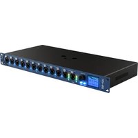
- INSTALLING MAGICQ SOFTWARE & DRIVERS
- USING MAGICQ ON PCS AND MACS
- MAGICQ CONCEPTS
- MAGICQ LAYOUT
- PATCHING
- SETTING INTENSITY LEVELS
- CONTROLLING ATTRIBUTES
- PALETTES
- FX ENGINE
- PROGRAMMER
- OUTPUTS WINDOWS
- EDITING CUES
- CUE STACKS
- PLAYBACK
- BUTTONS
- FUNCTION
- ACTIVATE/RELEASE
- ADVANCED
- CHASE OPTIONS
- AUDIO
- ADVANCED PLAYBACK / CUE STACK OPTIONS
- LIVE PROGRAMMING (BUSKING)
- GROUP CUES
- EXECUTE WINDOW
- AUTOMATION
- MOTORISATION AND CUSTOMISATION
- COLOUR PICKER
- CONTROLLING MEDIA SERVERS
- HEAD EDITOR
- CHANNELS VIEW
- RANGES VIEW
- PALETTES VIEW
- MACROS VIEW
- USER ICONS
- HEADS WITH MULTIPLE ELEMENTS
- CUSTOM GEL LIBRARIES
- IMPORTING GDTF FILES
- CURVE EDITOR
- FX EDITOR
- NETWORK MANAGER
- REMOTE DEVICE MANAGEMENT (RDM)
- NETWORKING OF MAGICQ SYSTEMS
- MANUAL CONFIGURATION OF MULTI CONSOLE OPERATION
- REMOTE CONTROL OF MAGICQ
- CHAMSYS REMOTE PROTOCOL COMMANDS
- CONTROLLING MAGICQ USING UDP/IP
- CONTROLLING MAGICQ USING THE SERIAL PORT
- DJ
- MIDI
- TIMECODE SUPPORT
- REMOTE INPUT PORT
- SCENE
- SCENE SETTER
- MAGICQ VISUALISER
- BLIND VISUALISATION
- USING MAGICQ WITH OTHER VISUALISERS
- TRACKERS
- SETTINGS
- WING SETTINGS
- MONITOR SETTINGS
- TOUCH SCREEN SETTINGS
- MODE & SECURITY SETTINGS
- PROGRAMMING SETTINGS
- KEYPAD / ENCODER SETTINGS
- WINDOWS SETTINGS
- SYSTEM MANAGEMENT
- SOFTWARE & FIRMWARE UPGRADE
- HANDY HINTS
- MAGICQ SHORTCUTS
- TROUBLESHOOTING
- BUTTON FUNCTIONS
- LICENSING
- GLOSSARY
- CHAMSYS LTD
- CHAPTER
- INTRODUCTION
- MAGICQ SOFTWARE AND CONSOLES
- MAGICQ MQ500 STADIUM CONSOLE
- MAGICQ COMPACT SERIES
- MAGICQ WINGS FOR USE WITH PC/MAC
- PLUGGING UP
- DMX CONNECTIONS
- POWERING UP
- POWERING DOWN
- RESETTING THE CONSOLE
- HARD RESET
- POWER SUPPLY PROTECTION
- CARE OF YOUR MAGICQ CONSOLE
- SAFETY INFORMATION
- SECURITY INFORMATION
- DISPOSAL INFORMATION
- MAGICQ SOFTWARE
- MAGICDMX
- MAGICQ WINGS & INTERFACES
- GENETIX NODES
- MAGICQ ON WINDOWS
- DRIVERS FOR OLDER MAGICQ PRODUCTS
- CPKULTRA
- USER PERMISSIONS ON WINDOWS
- WARNING
- MAGICQ ON MAC
- TURNING OFF APP NAP
- MAKING THE MAGICQ FOLDER WRITEABLE
- MAGICQ ON LINUX
- IMPORTANT
- INSTALLING
- HIGH DPI SCREENS
- EXPORT QT_AUTO_SCREEN_SCALE_FACTOR
- YOU CAN SPECIFY A FRACTIONAL NUMBER (E.G. SPECIFY 1.5 TO MAKE IT 50% BIGGER)
- EXPORT QT_SCALE_FACTOR
- EXPORT QT_SCREEN_SCALE_FACTORS
- SIMPLE GENERIC CONSOLE
- TECHNICIAN TEST HEAD
- DEMO SHOWS
- TOUCH VIEW
- PLAYBACK MODE
- COPY AND PASTE TO EXTERNAL APPLICATIONS VIA THE CLIPBOARD
- MAGICQ PC / MAC RESTRICTIONS (DEMO MODE AND CORE MODE)
- DEMO MODE
- CORE MODE
- UNLOCKED MODE
- GENETIX / SNAKESYS DMX NODE UNLOCKING
- MAGICHD STAND ALONE RESTRICTION
- SHOW STORAGE
- OUTPUT CHANNELS
- HTP / LTP CHANNELS
- CUES
- PLAYBACKS
- PAGES
- FX
- WINDOW LAYOUTS
- SHIFT FUNCTIONS
- THE PROGRAMMER
- HELP
- PHYSICAL LAYOUT
- TOUCH SCREEN, ENCODERS & SOFT BUTTONS
- MAIN WINDOWS
- LAYOUTS
- ACTIVE WINDOW
- WINDOW SIZING
- SUPPORT FOR FIND IN MAGICQ WINDOWS
- SUPPORT FOR CUT AND PASTE IN MAGICQ WINDOWS
- STATUS AND DISPLAY WINDOWS
- DESKTOP-SNE24PT 27 JUL
- P1 ADD INV NET
- PROGRAMMER CLEARED
- HEAD CONTROL
- EDITOR BUTTONS
- KEYBOARD, KEYPAD, SELECT & CONFIRM WINDOWS
- COMMON ACTIONS
- ITEMS
- SETTING THE VALUE OF ITEMS
- OR
- NAMING ITEMS
- MOVING ITEMS
- COPYING ITEMS
- REMOVING ITEMS
- RECORDING ITEMS
- ICONS
- CUSTOM PHOTO ICONS
- ACTIONS ON PLAYBACKS
- QUICK START
- STARTING UP MAGICQ
- CALIBRATING THE TOUCH SCREEN
- STARTING A NEW SHOW
- ENABLING OUTPUTS
- USING DIRECT DMX OUTPUTS
- USING OUTPUTS VIA NETWORK
- CONNECTING A MAGICQ PLAYBACK WING
- SETTING PLAYBACK WING IDS
- CONNECTING EXTERNAL MONITORS
- NAMING AND NUMBERING FIXTURES
- CONTROLLING HEADS
- SELECTING HEADS
- SELECTING HEADS FROM THE GROUP/HEADS WINDOW
- RECORDING A GROUP
- NAMING A GROUP
- RECALLING A GROUP
- SETTING LEVELS FOR DIMMERS
- LOCATING HEADS
- MODIFYING ATTRIBUTES
- RECORDING A PALETTE
- ADDING IN FX
- RECORDING A CUE
- RECORDING A CUE STACK (CHASE OR THEATRE STACK)
- SELECTING AND RECORDING COMPLETE WINDOW LAYOUTS
- SAVING THE SHOW
- PATCHING ON MAGICQ
- GETTING STARTED WITH PATCHING
- PATCHING A HEAD OR DIMMER
- HEAD NAMES AND HEAD NUMBERS
- HEAD NAMES
- HEAD NUMBERS
- RENUMBERING HEAD NUMBERS
- PATCHING TO SPECIFIC HEAD NUMBERS
- GEL NAME AND NUMBER
- COL TAGS
- GENERATING AUTO GROUPS
- AUTO PALETTES
- DUPLICATED HEADS
- MULTI ELEMENT HEADS
- INVERTING AND SWAPPING
- PAN AND TILT OFFSETS
- APPLYING OFFSETS USING UPDATE
- MINIMUM AND MAXIMUM LEVELS
- LIMITS AND OFFSET
- DIMMER CURVES
- TESTING CHANNELS
- CHANGING THE DMX ADDRESS OF HEADS
- PATCHING A HEAD TO MULTIPLE DMX ADDRESSES
- UNPATCHING A HEAD FROM A DMX ADDRESS
- PATCHING SCROLLERS
- EDITING HEADS
- CLONING (ADDING EXTRA HEADS / DIMMERS TO A PROGRAMMED SHOW)
- COPY HEAD PROGRAMMING
- PATCH CHANNEL COPY
- MORPHING HEADS (CHANGING HEAD TYPE)
- MORPHING MULTI ELEMENT HEADS
- MORPHING HEADS WITH VIRTUAL DIMMERS
- MORPHING BETWEEN CMY AND COLOUR WHEEL HEADS
- IMPORTING HEADS
- SUPPORTED COLUMN HEADINGS
- WYSIWYG
- VECTORWORKS
- DEPENCE
- CREATING A HEAD LIST
- EXPORTING HEADS
- VL5 TYPE CHANNELS (SPLIT PERSONALITIES)
- MERGING WITH DMX INPUT
- CUSTOMISING LOCATE, DEFAULT, HIGHLIGHT AND LOWLIGHT VALUES
- THEATRE PATCH SYNTAX
- VIRTUAL DIMMERS
- QUICKLY ADDING VIRTUAL DIMMERS TO PATCHED HEADS
- HEADS ALWAYS WITH VIRTUAL DIMMERS
- PATCH HEAD FILTERING
- DUPLICATED ELEMENTS OPERATING INDEPENDENTLY
- USING THE ON-SCREEN FADERS
- USING THE ENCODERS
- USING THE KEYPAD
- SETTING FADE TIMES FROM THE KEYPAD
- SETTING INTENSITY FX FROM THE KEYPAD
- SETTING INTENSITY LEVELS FOR DMX CHANNELS
- USING SELECTED HEADS
- USING GEL COLOURS IN THE INTENSITY WINDOW
- PROGRAMMING OF DIMMERS USING GEL COLOURS
- SETTING LEVELS WHILST RUNNING A SHOW
- INBUILT INTENSITY MASTERS
- VIEWING INTENSITIES IN THE OUTPUTS WINDOW
- USING GROUPS
- SETTING GROUP ICON OR COL TAG
- SELECTING HEADS USING THE KEYPAD
- HEAD 101 ENTER
- ENTER
- SELECTING MULTIPLE HEADS FROM THE KEYPAD
- THRU ENTER
- ALT ALL
- SELECTING GROUPS FROM THE KEYPAD
- SELECTING PALETTES FROM THE KEYPAD
- REMOVE DIMMER (REM DIM) FUNCTION
- SELECTING HEADS USING THE RIG PLAN VIEW
- HEAD MACROS
- FLIP / MIRROR
- SETTING ATTRIBUTE VALUES USING THE KEYPAD
- REVERSING ROTATIONS
- SNAP COLOUR
- DEFAULT COLOUR
- SELECTING INDIVIDUAL HEADS
- SINGLE MODE
- PAIR
- ODD/EVEN
- SEGMENTS
- ALL
- SUB SELECTING GROUPS
- SUB SELECTING HEADS USING SPECIFIC PALETTES
- CHANGING OVERALL SELECTION ORDER
- SUB SELECTION OF HEADS FROM GROUPS / OVERALL SELECTION
- SUB SELECTION OF ELEMENTS
- HEAD ELEMENT SELECTION
- ELEMENT SELECTION IN THE GROUP WINDOW
- GROUPS WITH ELEMENT SELECTION
- SUB GROUPS
- GROUP TYPE
- HIGHLIGHT MODE
- LOWLIGHT FUNCTION
- RESELECTING HEADS USING PALETTES AND INTENSITIES (ACTIVE PALETTE AND INTENSITY)
- FAN MODE
- AND ONLY
- GROUP WINDOW
- USING PALETTES
- RECORDING PALETTES
- RECORDING INDIVIDUAL ATTRIBUTES INTO A PALETTE
- RECORDING ONLY THE SELECTED HEADS
- INTENSITY PALETTES
- DUPLICATE ELEMENTS IN PALETTES
- NAMING PALETTES
- UPDATING PALETTES
- COPYING AND MOVING PALETTES
- REMOVING ATTRIBUTES FROM PALETTES
- VIEWING / EDITING PALETTE CONTENTS
- LINKED PALETTES
- USING PALETTES WITH TIMES
- FADING OVER GROUP GRIDS
- USING FAN
- MAKING PALETTES INTO CUE STACKS
- MERGING OF PALETTES FROM ANOTHER SHOW
- MODIFYING PALETTES IN THE PERSONALITY
- CAPTURING PALETTES FROM DMX INPUT
- MANUAL PALETTE CAPTURE
- AUTO PALETTE CAPTURE
- MANUAL CAPTURE FROM PALETTE WINDOWS
- MANUAL INCLUDING INTO THE PROGRAMMER
- EXPANDING PALETTES
- REPLACING PALETTES IN CUES
- TRACKER PALETTES
- DEFAULT PALETTES
- FX SPEED & SIZE
- FX BASE VALUES
- FX ADD MODES
- FX SPREAD (OFFSETS OVER HEADS)
- FX PARTS
- FX SEGMENTS
- FX DIRECTION & INVERSION
- WIDTH
- SPEED TYPE
- RND
- ONE SHOT
- TIMING
- FX FADE TIMES
- FX DELAY TIMES
- INITIAL SPREADS
- FX ON CMY AND RGB HEADS
- FLICKER FX
- MULTIPLE FX
- JOINING / SPLITTING MULTIPLE FX
- MODIFYING FX FOR SELECTED HEADS
- CHANGING FX
- FX REORDERING
- BLOCKING FX
- GENERATING USER FX
- EDITING USER FX
- PALETTE FX
- PALETTE FX ON HEADS WITH DIFFERENT ATTRIBUTES
- USER CREATED PALETTE FX
- FX COLOUR FLICKS
- FX USING BASE COLOUR
- GROUP BASED FX
- GROUP FX SPREAD
- FX ON HEADS WITH DUPLICATED ELEMENTS
- FX WINDOW
- FX PALETTES
- IMPORTING AND EXPORTING THE FX LIBRARY
- WHAT IS IN THE PROGRAMMER
- CLEARING THE PROGRAMMER
- ACTIVATION BY CHANNEL OR BY HEAD
- LEVELS
- SPLIT CUE TIMES
- VIEW SIMPLE
- FADE TYPE
- VIEW ADVANCED
- RECORDING TO A SPECIFIC CUE ID
- SNAPSHOT ICONS
- RECORD OPTIONS
- RECORD SHORTCUTS
- MASKING
- OPTIONS
- ACTIVE
- REMOVING CHANNELS FROM THE PROGRAMMER
- REMOVING CHANNELS USING THE REMOVE BUTTON
- REMOVING CHANNELS USING THE PROGRAMMER WINDOW
- MAKING CHANNELS HARD VALUES
- COPY BETWEEN HEADS
- BLIND PROGRAMMING
- PARKING (FREEZING) CHANNELS
- HEADS VIEW
- INTENSITY VIEW
- DMX CHANNELS VIEW
- MOVEMENT VIEW
- CHART VIEW
- PLAN VIEW
- CREATING RIG PLANS
- INSERTING HEADS USING HEADS NUMBERS
- INSERTING HEADS USING INSERT HEADS
- OUTPUT GRID MULTI HEAD SUPPORT
- OUTPUT GRID DISPLAY TYPES
- OUTPUT GRID REPATCHING
- OUTPUT GRID OPTIONS
- OUTPUT GRID ACTIONS
- IMPORTING AND EXPORTING GRIDS
- SELECTION OF HEADS IN OUTPUTS PLAN VIEW
- GROUPS WITHIN GRIDS
- KEY MACROS IN GRIDS
- EXEC ITEMS AND TEXT IN GRIDS
- INCLUDING CUES INTO THE PROGRAMMER
- INCLUDING CUES AT A SPECIFIED LEVEL
- SNAPSHOT
- EDITING USING THE INCLUDE AND UPDATE METHOD
- RECORD MERGE (UPDATING A CUE WITH THE CONTENTS OF THE PROGRAMMER)
- MAKING CHANGES TO MULTIPLE CUES
- CHANGES TO MULTIPLE CUES USING KEYPAD
- CHANGES TO MULTIPLE CUES USING CUE STACK WINDOW
- EDITING USING UPDATE
- DIRECT MODIFICATION OF INTENSITIES IN CUES
- COPY HEADS IN CUES
- CUE STACK WINDOW
- CHASE TIMING
- CUE TIMING
- CUE TIMING EXAMPLE
- THE HALT FIELD
- CUE DELAY AND FADE TIMES
- TRACKING
- TRACKING ON MAGICQ
- VIEWING CUE DATA AND TRACKING DATA
- TRACKING OUT FX
- COPYING CUES IN TRACKING MODE
- BLOCKING / UNBLOCKING CUES
- CUE ONLY
- MARK CUES
- THE CUE STORE AND CUE STACK STORE
- CUE STORE
- STACK STORE
- ASSIGNING CUES AND CUE STACKS
- COPYING AND MOVING CUES
- LINKED CUES
- COPYING CUE STACKS
- SELECTIVE COPYING OF CUE STACKS
- CREATING A NEW CUE STACK FOR DIFFERENT HEADS
- REMOVING CUES AND CUE STACKS
- CUE STACK DEFAULTS
- CUE STACK FAVOURITES
- AUDIO IN CUE STACKS
- AUDIO CUE STACK
- AUDIO FX CUES
- AUDIO FORMATS
- AUDIO VOLUME
- CUE STACK MACROS
- CONTROLLING SPEED MASTERS
- TIMECODE CUE STACKS
- EDITING TIMECODE
- LEARN TIMING
- TESTING TIMECODE
- EXTERNAL TIMECODE
- TIMECODE OFFSET
- AUTOMATIC ACTIVATION AND RELEASE OF PLAYBACKS
- INTERNAL TIMECODE
- ENABLING / DISABLING TIMECODE
- CUE STACK TIMECODE TRACKS
- IMPORTING TIMECODE TIMINGS
- REAPER
- NAME,START,END,LENGTH,COLOR R1,INTRO,0:00:00:00,0:00:02:00,0:00:02:00, M1,ACCENT,0:00:00:11,,FFF80A
- AUDACITY
- MAKING CUES
- TIMELINE
- VIEW SHEET
- VIEW CUELINE
- VIEW EDITOR
- VIEW CUE STACK
- VIEW MARKER OPTIONS
- BEAT MARKERS
- MARKER SET LAYERS
- CHOOSE CUE STACK
- AUDIO FILES
- PLAYHEAD
- TIMECODE TRACKS
- TIMECODE LOOP
- PLAYBACK DISPLAY
- ACTIVATING AND RELEASING PLAYBACKS
- FADER CONTROL
- PLAYBACK BUTTONS
- PLAYBACKS WITHOUT FADERS
- GRAND MASTER & SUB MASTER
- DEAD BLACK OUT (DBO)
- ADD / SWAP
- PAGE SELECT
- PAGE LEVELS
- CURRENT PLAYBACK
- PLAYBACKS ACROSS MULTIPLE PAGES
- PAGE HOLDOVER
- PLAYBACK BANKING
- MANUAL CONTROL
- GOTO
- MANUAL SPLIT CROSSFADE
- RATE SUB MASTER
- TAP TO TIME
- GLOBAL TAP TO TIME
- PLAYBACKS WINDOW
- TESTING PLAYBACKS
- NAMING PLAYBACKS
- COPYING AND MOVING PLAYBACKS
- REMOVING PLAYBACKS
- PLAYBACK RATE
- CHECKING ACTIVE PLAYBACKS
- MOVING PLAYBACKS FOR ALL PAGES
- SPEED MASTERS
- BANK PAGES
- DEFAULT CUE STACKS
- SYNCHRONISING PLAYBACKS
- SET LISTS
- CUE STACK OPTIONS
- FADERS
- FADER ACTIVATES STACK
- FADER RELEASES STACK
- FADER CONTROLS HTP CHANS
- FADER CONTROLS LTP (IPCB) CHANS
- FADER BLOCKS FX ON LTP CHANS
- FADER CONTROLS ABSOLUTE CHANS
- FADER CONTROLS FX SIZE
- FADER CONTROLS FX SPEED
- FADER CONTROLS MANUAL CROSSFADES
- FADER CONTROLS TIMING
- FADER CONTROLS AUDIO VOLUME
- FADER JUMPS TO CUE STEP
- ENCODER MODE
- CONTROL TYPE
- CONTROL ITEM
- FLASH ACTIVATES STACK
- FLASH RELEASES STACK
- FLASH ALWAYS SWAPS
- FLASH ACTS AS GO/PAUSE
- FLASH ACTS AS FLASH + GO
- FLASH TOGGLES
- FLASH ACTS LIKE FADER
- GO ACTIVATES STACK
- GO JUMPS OUT OF LOOP
- GO STOP/STARTS
- GO USES EXEC GRID
- PAUSE SWAPS
- PAUSE RELEASES
- PAUSE USES EXEC GRID
- CUE STACK IS AN INTENSITY MASTER
- CUE STACK IS A FX SIZE MASTER
- CUE STACK IS A FX SPEED MASTER
- GROUP ID (0 IS NOT USED)
- GROUP ATTRIBUTES
- INTENSITY MASTER TO
- CUE STACK IS A PROG MASTER
- CUE STACK IS A SPEED MASTER
- CUE STACK IS A LIVE COPY MASTER
- LIVE COPY GROUP ID
- COL TAG
- HALT AT LAST STEP
- RELEASE AFTER LAST STEP
- RELEASE RESETS TO FIRST STEP
- RELEASE STEPS 1 STEP
- RELEASE TIME
- RELEASE ATTRIBUTES
- RELEASE USES LAST STEP TIMES
- RELEASE FADES AUDIO
- RELEASE EXECUTES LAST STEP
- ACTIVATE ON PAGE CHANGE
- RELEASE ON PAGE CHANGE
- HTP ALWAYS ACTIVE (USE HTP)
- ACTIVATE AND RELEASE ON DJ SYSTEM
- ALL CHANS CONTROLLED LTP
- BLOCK FX FROM OTHER PLAYBACKS
- IGNORE MASTERS
- PLAYBACK PRIORITY
- MOVE WHEN DARK
- RECALCULATE STATE ON JUMPS
- STOMP OTHER PLAYBACKS
- SYNC NEXT PLAYBACK TO THIS ONE
- SEND PLAYBACK STATE TO OTHER CONSOLES
- RATE DIVISOR
- SPEED MASTER
- ENABLE TIMECODE LOOP
- TIMECODE LOOP IN
- TIMECODE LOOP OUT
- DJ TRACK
- TRACK DJ DECK TIMECODE
- SKIP FIRST TIMES
- SPEED
- XFADE
- DIRECTION
- REPEAT TYPE
- NUMBER OF REPEATS
- RUNNING
- HTP IN FADE, HTP OUT FADE, POSITION FADE, COLOUR FADE, BEAM FADE
- HTP IN DELAY, HTP OUT DELAY, POSITION DELAY, COLOUR DELAY, BEAM DELAY
- AUDIO CONTROLS FADER LEVEL
- AUDIO LEVEL JUMPS TO CUE STEP
- AUDIO BUMPS GO/FX
- AUDIO BEAT STEP
- AUDIO BEAT STEP LENGTH
- AUDIO SETS BPM
- AUDIO CHANNEL
- AUDIO LEVEL
- AUDIO PARAMETER
- AUDIO FILE
- AUDIO PLAY MODE
- STEP (VIEW DEFAULTS ONLY)
- STEP CONTROLLED AS A CHASE
- STEP FOLLOWS LAST
- STEP HALTS BEFORE EXECUTING
- ZERO OLD HTP (FROM PREVIOUS STEPS)
- ZERO OLD FX (FROM PREVIOUS STEPS)
- RELEASE OLD CHANS
- STEP TIMES (VIEW DEFAULTS ONLY)
- HTP IN FADE
- HTP OUT FADE
- POSITION FADE
- COLOUR FADE
- BEAM FADE
- HTP IN DELAY
- HTP OUT DELAY
- POSITION DELAY
- COLOUR DELAY
- BEAM DELAY
- FX (VIEW DEFAULTS ONLY)
- DEFAULT IN FADE
- DEFAULT OUT FADE
- INTERACTION OF HTP AND LTP CHANNELS BETWEEN PLAYBACKS
- HTP HANDLING
- LTP HANDLING
- HTP ALWAYS ACTIVE (USE HTP) OPTION
- INTERACTION OF FX BETWEEN PLAYBACKS
- BY DEFAULT, ALL PLAYBACKS HAVE THE SAME PRIORITY. IT IS POSSIBLE TO SET A PLAYBACK TO MAXIMUM PRIORITY USING THE CUE STACK OPTION "HIGHEST PLAYBACK PRIORITY". THE OPTIONS ARE
- SOMETIMES IT IS NECESSARY TO PROGRAM PLAYBACKS THAT ARE NOT AFFECTED BY THE GRAND MASTER OR SUB MASTER. USE THE "IGNORE MASTERS" OPTION TO PREVENT THE CUE STACK BEING AFFECTED BY THE MASTER FADERS – THIS IS USEFUL FOR CONTROLLING CHANNELS THAT MUST STAY UP – E.G., HOUSE LIGHTS, SMOKE MACHINES, ETC. CUE STACKS SET WITH THIS OPTION ARE NOT AFFECTED BY GRAND MASTER, SUB MASTER, DBO BUTTON
- PLAYBACK STOMPING
- GROUP MASTERS (INHIBIT MASTERS)
- INTENSITY MASTERS
- GROUP BASED INTENSITY MASTERS
- CHANNEL BASED INTENSITY MASTERS
- FX SIZE AND FX SPEED MASTER
- GROUP BASED FX SIZE AND FX SPEED MASTERS
- CHANNEL BASED FX SIZE AND FX SPEED MASTERS
- ADVANCED ACTIVATE AND RELEASE OPTIONS
- ADDING INDIVIDUAL CHANNELS USING PRESET FADERS
- OVER-RIDE / TAKE-OVER
- VIEWING CUES AND CUE STACKS
- MODIFYING CHASE SPEED / CROSSFADE
- MODIFYING FX PARAMETERS
- STOP / STARTING CUE STACKS
- JUMPING TO A CUE IN A CUE STACK
- OVER-RIDING USING THE PROGRAMMER
- ADDING IN NEW FX
- APPLYING PALETTES WITH TIME
- RELEASING / CLEARING WITH TIME
- SPEED CONTROL
- CHANGING THE CHASE OR FX DATA
- GLOBAL RATE OR PLAYBACK RATE
- FX SPEED ON PLAYBACK FADER
- FX SPEED MASTERS
- SPEED MASTER FADER MODE
- BUSKING MASTER
- PROGRAMMER MASTER
- LIVE MACRO
- PROG STORE
- GROUP LEVELS
- FANNING
- GROUP ELEMENTS
- FADE TIMES
- RECORDING
- INCLUDING / UPDATE
- ACTIVE / SNAPSHOT
- COPYING HEAD VALUES
- FILE SAVING / EXPORTING / MERGING
- UPDATING GROUPS
- UPDATING CUES
- DESIGN VIEW
- FULL SCREEN VIEW
- PASSWORD PROTECTION
- AUTOMATED START
- SIZING OF ITEMS
- REGIONS
- RATE AND PARAMETERS
- EXECUTE WINDOW FX
- EXECUTE WINDOW SOFT PALETTES
- EXECUTE WINDOW SEQUENCING
- EXECUTE WINDOW GROUP
- BUTTON APPEARANCE
- SPEED ENCODERS
- ATTRIBUTE ENCODERS
- PRELOAD
- BACKGROUND
- ASSIGNING EXECUTE PAGES TO USERS
- SPECIAL OPTIONS
- CHANGING EXECUTE PAGE
- AUTOMATING SETUP OPTIONS
- NET SESSION
- MULTI CONSOLE CONTROL SHORTCUTS
- TIMECODE AND TIMINGS
- USER
- EXECUTE WINDOW PLAYBACK / CUE STACK INFORMATION
- EXECUTE GRID USE SPEED MASTER
- EXECUTE WINDOW ON IOS/ANDROID REMOTE
- EXECUTE BUTTONS ON GO/PAUSE BUTTONS
- MULTIPLE EXECUTE WINDOWS
- MAGICQ AUTOMATION WINDOW
- AUTOM EVENTS
- AUTOM FUNCTIONS
- MIDI EVENTS
- SERIAL PORT EVENTS
- MIDI SYSEX EVENTS
- SCHEDULED EVENTS
- DATES AND DAYS OF THE WEEK
- SUNRISE + SUNSET (ASTRONOMICAL)
- TRACKER
- AUTOMATED START OF PLAYBACKS / EXECUTES
- KEYBOARD MACROS
- RECORDING KEYBOARD MACROS
- PLAYING KEYBOARD MACROS
- KEYBOARD MACRO TIMING
- EDITING KEYBOARD MACROS
- ASSIGNING KEYBOARD MACROS
- QUICK MACRO TOOLBAR
- RECORDING PLAYBACK FADERS
- IN BUILT MACROS
- SCHEDULED EVENTS IN CUE STACKS
- STADIUM PLAYBACK BANKING
- FADER MODES
- PROGRAMMER MODES
- MASTER MODES
- CUE MODES
- PRESET MODES
- SHORTCUTS TO FADER MODE
- FADER TOUCH
- DISABLING MOTORISATION
- ILLUMINATED FADERS
- PLAYBACK ENCODERS
- ILLUMINATED PLAYBACK ENCODERS
- LED & PIXEL MAPPING
- PATCHING LED ON MAGICQ
- USING THE GRID VIEW IN THE OUTPUTS WINDOW
- INSERTING HEADS INTO THE GRID USING HEAD NUMBERS
- INSERTING USING INSERT HEADS
- INSERTING USING THE SPARE HEADS BELOW THE GRID
- OPTIMISE GRID
- USING THE GRID
- PIXEL MAPPER
- USING BITMAPS, MOVIES, TEXT AND FX ON GRIDS
- MEDIA PRIORITY
- INBUILT BITMAPS
- USER PICTURE SUPPORT
- GOBO / COLOUR LIBRARIES
- MOVIE SUPPORT
- MOVIE MODE
- GIF ANIMATIONS
- LIVE FEED SUPPORT
- MAGICCAP
- USING TEXT STRINGS
- TEXT DISPLAY MODES
- MANIPULATING BITMAPS AND TEXT
- PIXEL MAP FX
- PIXEL MAP AUDIO FX
- MIXING BETWEEN PIXEL MAPPING LAYERS
- COLOUR MIXING
- APPLY TYPE
- D PIXEL MAPPING
- CONFIGURATION
- EFFECTS
- SLIDE
- PARTICLES
- COL OFFSET
- HEIGHTMAP
- FULL UP AND FILL DOWN
- PARTICLE BOUNCE
- SIMPLE PIXEL MAP FX
- SETTING UP GROUP GRIDS
- ADDING SI
- PALETTE BASED SIMPLE PIXEL MAP FX
- USING SIMPLE PIXEL MAP FX ON USER GRIDS
- MAKING GRIDS OF GROUPS
- AUTO GROUPS
- PROGRAMMING LED USING STANDARD FX
- USING GROUPS AUTO GENERATED FROM THE GRID
- MAKING GROUPS OUT OF LED PIXELS
- MAKING NEW LED PERSONALITIES ON MAGICQ
- OUTPUT GRID TO EXTERNAL MONITORS
- CONCEPTS
- COLOUR SPACES
- CIE
- RGB
- HSL
- CCT
- GAMUT & COLOURIMETRY
- BRIGHTNESS, LUMINOSITY
- VIEWS
- WHEEL
- GELS
- SELECTION MODES
- SELECT SINGLE
- SELECT FAN
- SELECT RELATIVE
- OTHER FUNCTIONS
- PATCHING MEDIA SERVERS ON MAGICQ
- CONNECTING VIA NETWORK
- SETTING UP CONTROL OF THE MEDIA SERVER
- CONFIGURING THE MEDIA WINDOW
- SIMPLE MEDIA SETUP
- ADVANCED MEDIA SETUP
- MAGICHD
- ARKAOS
- CATALYST
- COOLUX
- HIPPOTIZER
- MAXEDIA
- MBOX
- MEGAPIXEL VR HELIOS SUPPORT
- OTHER MEDIA SERVERS
- THUMBNAIL VIEW
- LIVE PREVIEWS
- MEDIA WINDOW VIEW
- USING MAGICQ AND MEDIA SERVER SOFTWARE ON THE SAME PC
- USING MAGICHD
- USING THE LOOPBACK IP ADDRESS
- CITP (MSEX) LIVE FEEDS AND MAGICCAP
- HOW HEADS ARE STORED IN MAGICQ
- EXPANDING LIBRARY HEAD FILES
- LOADING NEW HEADS INTO MAGICQ
- COPYING HEAD FILES CREATED ON PC/MACS TO MAGICQ CONSOLES
- MODIFYING EXISTING HEADS
- REMOVING OLD HEADS
- GENERAL VIEW
- NAMES
- DMX
- PARAMS
- MULTI
- MEDIA
- NAME AND TYPE
- ATTRIB NO
- ENC
- SIZE, INSTANT AND SLOW ENCODER
- DEFAULT AND LOCATE
- HIGHLIGHT / LOWLIGHT
- ELEMENT
- INDEPENDENT
- SELECT
- FUNCTION TYPE
- IMPORTING RANGES
- CAPTURING RANGES
- ATTRIBUTE TEST
- IMPORTING PALETTES
- CAPTURING PALETTES
- CREATING DUPLICATED HEADS
- PATCHING HEADS WITH DUPLICATED ATTRIBUTES
- CUSTOM ELEMENT LAYOUT
- ADDING COLOURIMETRY DATA TO A HEAD
- OLD MAGICQ MULTI ELEMENTS
- GDTF TROUBLESHOOTING
- CREATING A CURVE
- EDITING A CURVE
- SETTING A DIMMER CURVE
- VIEW GENERAL
- VIEW CHANS
- VIEW CHAMNET
- DEVICES
- CONFIGURING ENTIRE DEVICES
- IDENTIFY
- PORTS
- DMX FALLBACK
- GENETIX PORT LEDS
- SCENES
- CONFIGURING SCENES
- TRIGGERING SCENES
- IP ADDRESS AND SUBNET MASK
- SYNC
- LEDS
- ACTIVE SCENE
- LOST DATA
- RDM
- USER CONFIG
- PIN LOCK
- TIMECODE
- SCENE MODE
- LEGACY SNAKESYS NODES
- CHAMNET MODE
- OLDER CHAMSYS 4 PORT ETHERNET INTERFACES
- UPGRADING GENETIX AND SNAKESYS FIRMWARE
- OUTPUT SETUP
- VIEW ART-NET
- VIEW SACN
- VIEW RDM
- DISCOVERING AND CONFIGURING DEVICES
- UNI
- TYPE
- RDM UNI
- ADDR
- CHANS
- PER
- TOT
- MANUFACTURER
- MODEL
- MODE
- UID
- DEVICE MODEL ID
- CURVE
- FREQ
- RESET
- FACTORY RESET
- CABLE INDEX
- SEL PID
- AUTO ADDRESSING
- RESTORE ADDRESSING
- IDENTIFYING DEVICES
- SENSORS
- AUTO PATCHING
- ESTA MANUFACTURER ID (HEX)
- RDM DEVICE MODEL ID (HEX)
- RDM PERSONALITY NUMBER
- CREATING HEADS FROM RDM DATA
- MANUAL REPATCH
- READDRESS PHYSICAL FIXTURES
- REPATCH SHOW TO FIXTURES
- BACKGROUND CHECK
- AUTO PATCH
- RIG LOCK
- VIEW PIDS
- VIEW LYNTEC
- NETWORK ADDRESSES AND HOST NAMES
- SETTING IP ADDRESSES ON A PC
- SETTING IP ADDRESSES ON A MAC
- CHECKING IP ADDRESSES - PING TEST
- CHECKING CONSOLES ON THE NETWORK
- GRABBING SHOWS FROM OTHER CONSOLES
- SETTING UP NETWORK SESSIONS
- MANUAL TAKEOVER
- AUTO TAKEOVER
- NET SESSIONS MASTER CLASH
- INHIBIT OUTPUTS
- MULTI CONSOLE PROGRAMMING
- USERS IN NET SESSIONS
- CHECKING SLAVE SYNCHRONISATION
- SELECTIVE CHANNEL CONTROL
- SELECTING WHICH CONSOLE CONTROLS WHICH CHANNELS
- RESTRICTED FEATURES ON SLAVE CONSOLES
- PLAYBACK SYNC MODES
- PROGRAMMER SYNC MODES
- INCLUDE FROM OTHER CONSOLE
- UNIVERSE ZONING
- INTER CONSOLE MESSAGING
- CONTROL NETWORK
- CONFIGURING
- COMPATIBILITY
- MANUAL CONFIGURATION OF HOT TAKE-OVER
- HOT TAKEOVER MODE
- PREFERRED MODE
- EQUAL MODE
- SPLIT MODE
- HOT TAKE-OVER TYPE
- SWAPPING CONTROL BETWEEN MULTIPLE CONSOLES
- EMERGENCY HOT TAKEOVER
- MANUAL CONFIGURATION OF PLAYBACK SYNCHRONISATION
- CONFIGURING WHICH CONSOLES PLAYBACK SYNC TO WHICH CONSOLES
- MANUAL CONFIGURATION OF SHOW DATA SYNCHRONISATION
- MANUAL CONFIGURATION OF SELECTIVE CHANNEL CONTROL
- AUTOMATIC BACKING UP OF SHOWS FROM OTHER CONSOLES
- MAGICQ REMOTE CONTROL (WINDOWS/MAC/LINUX)
- REMOTE CONTROL FROM MAGICQ
- IOS / ANDROID REMOTE APP
- SETTING UP AN ACCESS POINT
- INBUILT WIRELESS
- CONNECTING THE REMOTE APP VIA ETHERNET
- MAKING A CONNECTION TO MAGICQ
- MODIFYING PALETTES WITH THE REMOTE APP
- USING THE EXECUTE WINDOW
- RESTRICTING ACCESS (EXECUTE MODE)
- IN APP SETTINGS
- IN APP HELP
- KEY & FOCUS VIEW
- POS VIEW
- EXEC VIEW
- WIN VIEW
- REMOTE CONTROL VIA WEB SERVER
- CUSTOM WEB SERVER PAGES
- REMOTE CONTROL USING MAGIC WAND SIMULATOR
- REMOTE PLAYBACK COMMANDS
- REMOTE PROGRAMMING COMMANDS
- ATTRIBUTE NUMBERS
- CHAMSYS REMOTE ETHERNET PROTOCOL
- WRITING TO THE NETWORK PORT
- READING FROM THE NETWORK
- SAMPLE CODE FRAGMENTS
- CONNECTING THE SERIAL PORT
- ENABLING THE SERIAL PORT
- WRITING TO THE SERIAL PORT
- READING FROM THE SERIAL PORT
- TESTING RECEIVING SERIAL COMMANDS
- AUDIO INPUT
- AUDIO INPUT PORTS
- AUDIO INPUT OPTIONS
- GLOBAL AUDIO SETTINGS
- CUE STACK AUDIO OPTIONS
- PIXEL MAPPER AND AUDIO
- AUDIO PLAYBACK
- AUDIO OUTPUT PORTS
- MAGICQ PC
- USB SOUND CARDS
- CONTROL OF WINAMP
- SUPPORTED SYSTEMS
- VIRTUALDJ / OS2L
- STAGELINQ / ENGINE PRIME
- TCNET
- DECK CONFIGURATION
- AUDIO WINDOW
- TIMECODE AND LEVEL SYNCHRONISATION
- BEAT TRACKING
- DIAGNOSTICS
- MIDI NOTES AND CC RECEIVE
- MIDI AUTOM EVENTS
- MIDI LEARN
- MIDI MAPPING FILE
- ADVANCED MIDI MAPPING
- DEFAULT MEDITABLE.TXT FILE
- MIDI NOTES AND CC TRANSMIT
- PATCHING MIDI CHANNELS
- NOTE
- MIDI PROBLEMS
- MIDI SHOW CONTROL (MSC)
- MIDI SHOW CONTROL COMMAND FORMAT
- MIDI BEAT CLOCK
- MAGICQ USB MIDI/TIMECODE BOX FIRMWARE VERSIONS
- TIMECODE DECODE
- TIMECODE FROM WINAMP
- TIMECODE FROM MAGICHD
- TIMECODE SIMULATOR
- TIMECODE GENERATION
- FREE RUNNING TIMECODE
- USING CUE STACK INTERNAL TIMECODE
- USING THE TIMECODE SIMULATOR
- TIMECODE RE-TRANSMIT
- CONNECTION (MAGICQ CONSOLES, MAGICQ PC WING COMPACT AND MAGICQ MAXI-WING)
- CONNECTION (ORIGINAL PC WING)
- ENABLING THE REMOTE INPUT IN MAGICQ
- SCENE GATEWAYS
- SCENE WALL PLATES
- PROGRAMMING 10SCENE WALL PLATE IDS
- SCENE ENABLE
- SCENE ACTION
- PB1 TO
- EXEC
- EXEC 1 MULTI
- EXEC 1 GROUPS
- EXEC GRIDS
- CUSTOM
- MANUAL ZONE CONFIGURATION
- ZONE MODE
- ZONE STATUS
- ZONE NAME
- SCENE ID MIN AND MAX
- PASSWORDS
- PASSCODES
- JOINING ZONES
- SCENE REMOTE TRIGGERS
- SCENE REMOTE APP
- TESTING AN INSTALLATION
- POWERING THE SCENE SETTER
- USING THE SCENE SETTER
- CHANGING THE IP ADDRESS
- SETTING UP THE SERIAL PORT
- OPEN SOUND CONTROL (OSC)
- SETUP
- RECEIVING MESSAGES
- MAGICQ OSC ADDRESSES
- SENDING MESSAGES
- PATCHING OSC HEADS
- TOUCHOSC
- TRANSMIT OR RECEIVE NOT WORKING
- MESSAGES GETTING LOST
- NOTES
- MAGICVIS
- USING THE SEPARATE MAGICVIS APPLICATION
- USING MAGICVIS WITH OTHER CONSOLES
- TIP
- USING THE VISUALISER IN MAGICQ
- USING MAGICVIS
- PATCHING HEADS IN THE VISUALISER
- VIEW VIS VIEW
- POSITIONING THE HEADS IN THE VISUALISATION
- TRANSFORM MODES
- OBJECTS
- DRAPES
- CUSTOM MODELS
- ATTACHING HEADS TO OBJECTS
- MODIFYING BEAM ANGLE AND HEAD SHAPE
- VISUALISING MEDIA SERVERS
- MOVING TRUSSES
- COLOURED OBJECTS
- DMX CONTROLLED CAMERA
- REMOVING VISUALISER HEADS AND OBJECTS
- CHANGING THE SIZE OF THE ROOM
- PAPERWORK
- CONVERTING AN EXISTING MAGICQ SHOW FILE
- CONVERTING A MAGICQ GRID INTO A VISUALISATION
- VISUALISER SETTINGS
- PLOT WINDOW
- FOCUS FUNCTIONS
- CONVERTING THE PLOT VIEW INTO A MAGICQ GRID
- SPLIT VISUALISATION IN MAGICVIS
- AUTOMATIC SOURCE SELECTION
- CONNECTING TO A VISUALISER
- CAPTURE
- RECEIVING PATCH DATA FROM CAPTURE
- ENABLING MAGICQ TO OUTPUT WYSIWYG DATA
- RUNNING WYSIWYG
- AUTO FOCUS
- VISION, DEPENCE, L
- MQ TRACK PROTOCOL
- OBJECT TRANSFORM PROTOCOL
- PSN/SPOTME
- SCALING, OFFSETS AND SWAPS
- USING AUTOMATIONS WITH TRACKERS
- TRACKING A FIXED XYZ WHEN LIGHTING TRUSSES MOVING
- TRACKING A MOVING MAGICVIS OBJECT
- TRACKER SIMULATOR
- GENERIC TRACKER PERSONALITY
- MOVING VIS OBJECTS
- TRANSMIT TRACKER 1 / TRACKER 2 FROM FOCUS HOLD
- DMX INPUT TRACKING
- TRACKER DEMO SHOW
- SHOW SETTINGS
- CONSOLE SETTINGS
- PROGRAMMING MODE
- ADVANCED SETTINGS OPTION
- OUTPUT SETTINGS
- CONFIGURING OUTPUT UNIVERSES
- USING ART-NET
- USING SACN
- MAGICQ CONSOLES DIRECT OUTPUTS
- MAGICQ MQ500M STADIUM WING
- MAGICQ MINI CONNECT, COMPACT CONNECT, STADIUM CONNECT, MINI WING, PC WING AND MAXI WING
- MAGICQ DUAL DMX INTERFACES
- MAGICDMX INTERFACES
- SUPPORT FOR LUMEN RADIO NOVA
- RD PARTY DMX DONGLES
- TESTING OUTPUT UNIVERSES
- COPYING OUTPUT UNIVERSES
- HOT TAKE-OVER
- INPUT UNIVERSES
- MERGING DMX FROM ANOTHER CONSOLE
- CONNECTING A MINI CONNECT, COMPACT CONNECT OR STADIUM CONNECT
- CONNECTING GENETIX NODES (VIA USB)
- CONNECTING PLAYBACK WINGS AND EXTRA WINGS
- CONNECTING A MINI WING, PC WING OR MAXI WING
- CONNECTING AN EXECUTE WING
- CONNECTING MAGICQ CONSOLES TOGETHER
- USING AN EXTERNAL DMX CONSOLE FOR EXTRA PLAYBACKS
- MQ500(M) OPERATING SYSTEM
- MQ250M OPERATING SYSTEM
- COMPACT (MQ50/MQ70) OPERATING SYSTEM
- MQ80 OPERATING SYSTEM
- OLD COMPACT (MQ40N/MQ60/OLD MQ70) OPERATING SYSTEM
- MONITOR SETTINGS ON MAGICQ PC / MAC
- MOVING WINDOWS TO THE EXTERNAL MONITOR
- ADDITIONAL CUE STACK, OUTPUT, PROGRAMMER, MEDIA, EXECUTE, GROUP WINDOWS
- ADDITIONAL EXTERNAL SCREENS (MULTI WINDOWS) ON CONSOLES
- CONFIGURING AN EXTERNAL TOUCH SCREEN
- COUNTRY
- TIME ZONE
- LATITUDE
- LONGITUDE
- CONSOLE MODE (ADVANCED SETTINGS)
- PROGRAMMING
- MODIFICATIONS
- TEST MODE
- MACROS
- AUTOMS
- VISUALISER
- START MODE
- RUN IN EXECUTE WINDOW
- AUTO BACKUP
- KEEP A BACKUP ARCHIVE
- SHOW FILE PATH
- SHOW FILE FORMAT
- EXTRAS FILE CREATE MODE
- PERSONALITY FILE FORMAT
- ACTIVATE CHANS/HEAD
- PROGRAMMER TRACKING
- UNUSED CHANS RETURN TO DEFAULTS
- PROGRAMMER OVERRIDES HTP
- PROGRAMMER OVERRIDES FX
- SELECT MULTIPLE GROUPS
- RECORDING TO PALETTES
- RECORD MERGE OVERRIDES TIMES
- UPDATE CLEARS PROGRAMMER
- UPDATE DEFAULT
- UNDO MODE
- AUTO ENTER ON KEYPAD INTENSITY SET
- AUTO CURSOR DOWN ON ENTER
- SELECT HEADS ON KEYPAD INTENSITY SET
- SELECT HEADS AND PALETTES FROM KEYPAD
- SELECT HEADS ON INCLUDE
- KEYPAD ALWAYS SELECTS HEADS
- KEYPAD SYNTAX - THEATRE PATCH
- ENCODER SENSITIVITY
- SWAP PAN AND TILT ENCODERS
- SWAP ENCODER DIRECTION
- MAGICQ KEYBOARD MODE
- PROGRAMMING SHORTCUTS
- MAP KEYS TO THRU, @, FULL
- ENABLE MOUSE TO CONTROL PAN/TILT
- INTENSITY WHEEL
- COLOUR SCHEME
- BIG TEXT MODE
- ICON SIZE
- PLAYBACK COL TAGS
- SPEED DISPLAY
- ATTRIBUTE DISPLAY
- UNITS OF MEASUREMENT
- COLUMN SIZING
- NUM BOXES WIDE
- AUTO ROW ORDERING
- CONFIRMATION REQUESTS
- SCROLL BARS
- HELP MODE
- LAYOUT BUTTONS ALWAYS ACTIVE
- ALWAYS SHOW RECORD OPTIONS
- PLAN INTENSITY TYPE
- MESSAGE WINDOW
- CUE STORAGE SETTINGS
- REMOVE CUES WHEN REMOVE CUE STACKS
- REMOVE CUE STACKS ON REMOVE PLAYBACKS
- USE FIRST FREE CUES, STACKS, PALETTES
- COPY MODE (LINKED/UNLINKED)
- COPY HEADS
- DERIVE SETTINGS FROM PREVIOUS CUE
- HIDE CUE STORE IDS (QIDS)
- HIDE VDIMS
- EXPAND HEADS IN PALETTES
- AUTO CREATE DEFAULT PALETTES
- HEADS MOVED ASIDE ARE UNPATCHED
- DEFAULT MARK/MOVE WHEN DARK TIME
- PLAYBACK SETTINGS
- GRAND MASTER FUNCTION
- SUB MASTER FUNCTION
- CROSSFADE MASTER FUNCTION
- CROSSFADE BUTTON FUNCTION
- SPLIT CROSSFADE
- CROSSFADE CONTROLS PLAYBACK
- WING CROSSFADE MASTER FUNCTION
- DBO FUNCTION
- TAP FUNCTION
- STOMP PLAYBACKS
- INTENSITY (HTP) FX CAN ADD, SUBTRACT
- GO REASSERTS CHANNELS
- FADER OFF ZERO REASSERTS CHANNELS
- FADER MODE
- MOTOR FADERS RELEASE TO ZERO
- NEXT PAGE CHANGES TO NEXT USED
- CURRENT PLAYBACK FOLLOWS LAST TOUCHED
- PLAYBACKS S + GO = PAUSE
- TAP TO TIME BUTTONS
- INT MASTER APPLIES TO LTP CHANS
- ACTIVATE PLAYBACKS ON START
- PLAYBACK GO/PAUSE USE EXEC GRID
- PLAYBACK HOLDOVER MODE
- NETWORK SETTINGS
- IP ADDRESS
- SUBNET MASK
- GATEWAY ADDRESS
- NET HOST OPTIONS
- ART-NET TYPE
- SACN TYPE
- SACN TRANSMIT PRIORITY
- RDMNET IP ADDRESS
- RDMNET PORT
- NETWORK SWITCH
- IGMP QUERIER
- CONTROL NET MODE
- CONTROL NET IP ADDRESS
- CONTROL NET SUBNET MASK
- CONTROL NET FIREWALL
- VISUALISER IP ADDRESS
- VISUALISER TYPE
- VISUALISER OFFSET
- ETHERNET REMOTE PROTOCOL
- PLAYBACK SYNC PORT
- CUSTOM TCPIP TYPE
- CUSTOM TCPIP IP ADDRESS
- CUSTOM TCPIP PORT
- WEB SERVER
- WEB SERVER PORT
- OSC MODE
- OSC TX PORT
- OSC RX PORT
- OSC TX IP (0 = BROADCAST)
- TRACKER RX
- TRACKER TX
- OTP FUNCTION
- WIFI SETTINGS
- WIRELESS MODE
- WIRELESS IP ADDRESS
- WIRELESS SUBNET MASK
- WIRELESS CHANNEL
- WIRELESS SSID
- WIRELESS ENCRYPTION
- WIRELESS KEY
- WIRELESS DHCP SERVER
- ANDROID TETHERING SUPPORT
- PORT SETTINGS
- MAGICQ WINGS AND INTERFACES
- MAGICDMX MODE
- AUDIO INPUT DEVICE
- AUDIO MIN LEVEL
- AUDIO MAX LEVEL
- AUDIO OUTPUT
- AUDIO OUTPUT DEVICE
- AUDIO OUTPUT VOLUME
- AUDIO OUTPUT MUTE
- REMOTE TRIGGER TYPE
- REMOTE TRIGGER ACTION
- SERIAL COM PORT
- SERIAL BAUD RATE
- SERIAL PARITY
- SERIAL DATA BITS
- SERIAL STOP BITS
- SERIAL REMOTE PROTOCOL
- MIDI / TIMECODE SETTINGS
- TIMECODE FRAME TYPE
- TIMECODE CONTINUE FRAMES
- TIMECODE JUMP DETECT FRAMES
- TIMECODE BACKWARD JUMPS
- TIMECODE ACTIVATE/RELEASE
- MIDI IN TYPE
- MIDI IN CHAN
- MIDI OUT TYPE
- MIDI OUT CHAN
- MIDI SHOW CONTROL TYPE
- MULTIPLE CONSOLE SETTINGS
- ENABLE REMOTE CONTROL
- ENABLE REMOTE ACCESS
- NET SESSION MODE
- NET SESSION ID
- PLAYBACK SYNC SLAVE MODE
- PROGRAMMER SYNC MODE
- HOT TAKEOVER DETECT TIME
- HOT TAKEOVER FADE TYPE
- HOT TAKEOVER FADE TIME
- PLAYBACK SYNC TYPE
- PLAYBACK SYNC IP
- SHOW DATA SYNC TYPE
- SHOW DATA SYNC IP
- HARDWARE SETTINGS
- LEVEL ABOVE 0 TO ACTIVATE LTP
- HYSTERESIS ON FADER / ENCODER MOVES
- ENCODER DAMPING
- TOUCH SCREEN
- ENCODERS
- FAULTY FADERS MASK
- MOTORISATION
- FAULTY MOTOR MASK
- FAULTY WING MOTOR MASK
- POWER FAIL DETECTION
- SCREEN SAVE
- CLOSE DISPLAY ACTION
- REDUCED RATE OUTPUT
- DMX FRAME TIMING
- DISPLAY EDGE
- MOVIE BUFFER FRAMES (0=USE DEFAULT)
- DEBUG MODE (MUST BE 0)
- STANDARD LOGGING
- EXTENDED LOGGING
- GENERAL SETTINGS
- SPLASH SCREEN IMAGE
- INDIVIDUAL PLAYBACK SETTINGS
- DISPLAY BRIGHTNESS AND CONTRAST
- CONSOLE LAMP BRIGHTNESS
- BUTTON LED BRIGHTNESS
- CONTROLLING CONSOLE LAMP FROM THE PROGRAMMED SHOW
- LOCKING THE CONSOLE
- BUTTON TEST MODE
- STARTING UP
- SHUTTING DOWN
- SAVING SHOWS
- SHOW FILE NAME AUTO INCREMENT
- BACKING UP TO AN EXTERNAL SYSTEM
- LOADING SHOWS
- ERASING
- SHOW EXTRAS FILE
- IMPORT AND EXPORT OF SHOW DATA AND SHOW MERGING
- EXPORTING SHOWS
- MERGING / IMPORTING SHOWS
- ADVANCED MERGING
- MERGING IN PART OF ANOTHER SHOW FILE
- MERGING DIFFERENT VERSIONS OF THE SAME SHOW
- IMPORTING CUES FROM A DIFFERENT VERSION OF THE SAME SHOW
- USITT ASCII FILE IMPORT
- IMPORTING PATCH
- MVR FILE IMPORT
- SAVING AND LOADING SETTINGS
- FILE MANAGER
- TRANSFERRING FILES OVER NETWORK
- STORAGE OF MAGICQ USER FILES ON PC/MAC
- REPORTS
- STATUS WINDOW
- BACKUP ARCHIVES
- USING SHOWS ON DIFFERENT MAGICQ PRODUCTS AND SHOW VERSIONS
- LOADING A SHOW ONTO A SMALLER CONSOLE
- CONFIGURING NUMBER OF UNIVERSES
- MAGICQ PROFILES
- USER MANAGEMENT
- USER TYPES
- START OPTIONS
- ACCESS TO CONSOLE CHANNELS
- RESTRICTING REMOTE APP ACCESS
- USER SETTINGS
- SECURITY
- MULTI CONSOLE SETTINGS
- DMX I/O SETTINGS
- SAVING SUPPORT FILES
- COMMANDS AND LOGS
- CHANGING MAGICQ CONSOLE SOFTWARE
- CONSOLE KERNEL UPDATE
- MQ80 KERNEL V2 UPGRADE
- RESETTING A MAGICQ CONSOLE TO FACTORY DEFAULTS
- FIRMWARE
- MQ50, MQ70 AND MQ80 FRONT PANEL FIRMWARE
- PRE V1.9.5.3 SOFTWARE
- MQ250M STADIUM FIRMWARE
- MQ500 STADIUM FIRMWARE
- MQ500M STADIUM FIRMWARE
- MQ500M WING FIRMWARE
- COMPACT & MINI CONNECT FIRMWARE
- FIRMWARE CHANGE LOG
- CH346 FIRMWARE (MQ50, MQ70, MQ80, MQ500(M) MIDI CARD, MQ500(M) V2 DISPLAY CONTROLLER AND MQ250M DISPLAY CONTROLLER)
- CH310-021 FIRMWARE (MQ250M & MQ500M MOTOR BOARD)
- CH310-022 FIRMWARE (MQ250M & MQ500M PLAYBACK PANEL)
- CH310-023 FIRMWARE (MQ500M PROGRAMMER PANEL)
- CH310-025 FIRMWARE (MQ250M PROGRAMMER PANEL)
- CH310-028 FIRMWARE (COMPACT CONNECT)
- CH310-033 FIRMWARE (MINI CONNECT)
- UPDATING FIRMWARE
- UPGRADING TO LATEST FIRMWARE
- MANUAL FIRMWARE UPDATE
- UPGRADING LEGACY PRODUCT FIRMWARE
- ORIGINAL COMPACT SERIES MQ40/MQ40N/MQ60/MQ70 FIRMWARE
- NO OUTPUTS
- MAGICQ NOT RESPONDING
- MAGICQ RESPONDING SLOWLY
- STRANGE KEY PRESSES, UNEXPECTED WINDOW CHANGES
- MAGICQ CONSOLE NOT BOOTING
- MQ100 SERIES CONSOLE NOT BOOTING
- MQ80 CONSOLE BLANK SCREEN AND NOT BOOTING
- MQ80 CONSOLE MAGICQ NOT STARTING
- MQ50 / MQ70 / MQ250M CONSOLE MAGICQ NOT STARTING
- MQ40/60 CONSOLE NOT STARTING
- MAGICQ CONSOLE BLANK SCREEN
- MAGICQ CONSOLE WHITE SCREEN
- MAGICQ CONSOLE DISTORTED SCREEN
- MAGICQ CONSOLE INTERNAL TOUCH SCREEN NOT WORKING
- ALL 10 S BUTTONS FLASHING BLUE
- FADER, ENCODER, OR BUTTON NOT WORKING CORRECTLY
- UNABLE TO SAVE SHOWS OR PATCH HEADS AFTER PERFORMING A *777 ERASE ALL ON THE CONSOLE
- MAGICQ NEEDS TO WRITE TO THE INSTALL FOLDER..." MESSAGE ON MAC
- LINUX: MAGICQ FAILS TO START / LIBGL ERROR
- SHIFT
- CTRL
- ALT
- MIN
- MAX
- CLOSE
- NEXT WIN
- EXT
- SIZE
- PROG
- OUTPUTS
- PATCH
- VIS
- PLOT
- MACRO
- PAGE
- EXECUTE
- CUE
- CUE STACK
- GROUP
- HEAD
- INTENSITY
- POS
- COLOUR
- BEAM
- NEXT HEAD
- PREV HEAD
- LOCATE
- FAN
- HIGHLIGHT
- SINGLE
- ODD / EVEN
- MIRROR
- RELEASE
- BLIND
- CLEAR
- BACKSPACE
- SET
- RECORD
- REMOVE
- UNDO
- INCLUDE
- UPDATE
- COPY
- MOVE
- GO
- PAUSE
- S
- FLASH
- GRAND FLASH
- SUB FLASH
- NEXT PAGE
- PREV PAGE
- MANUAL GO
- MANUAL PAUSE
- BIG GO
- FAST FORWARD
- FAST BACK
- TAP
- DBO
- NUMERIC KEYS
- DOT
- DIVIDE
- MULT
- PLUS
- MINUS
- THRU
- FULL
- TIME
- PAGE LEFT
- PAGE RIGHT
- CURSOR KEYS
- TOP SOFT
- SIDE SOFT
- QT
- NO WARRANTY
- END OF TERMS AND CONDITIONS
- LIBPNG
- TRADEMARK
- OSI CERTIFICATION
- EXPORT CONTROL
- LIBJPEG
- LIBJPEG-TURBO
- LIBICU
- COPYRIGHT AND PERMISSION NOTICE
- CHINESE/JAPANESE WORD BREAK DICTIONARY DATA (CJDICT.TXT)
- AND TECHNOLOGY. ALL RIGHTS RESERVED
- USE, REPRODUCTION, AND DISTRIBUTION OF THIS SOFTWARE IS PERMITTED
- ANY COPY OF THIS SOFTWARE, WHETHER IN ITS ORIGINAL FORM OR MODIFIED
- MUST INCLUDE BOTH THE ABOVE COPYRIGHT NOTICE AND THE FOLLOWING
- PARAGRAPHS
- NARA INSTITUTE OF SCIENCE AND TECHNOLOGY (NAIST)
- THE COPYRIGHT HOLDERS, DISCLAIMS ALL WARRANTIES WITH REGARD TO THIS
- SOFTWARE, INCLUDING ALL IMPLIED WARRANTIES OF MERCHANTABILITY AND
- FITNESS, IN NO EVENT SHALL NAIST BE LIABLE FOR
- ANY SPECIAL, INDIRECT OR CONSEQUENTIAL DAMAGES OR ANY DAMAGES
- WHATSOEVER RESULTING FROM LOSS OF USE, DATA OR PROFITS, WHETHER IN AN
- ACTION OF CONTRACT, NEGLIGENCE OR OTHER TORTUOUS ACTION, ARISING OUT
- OF OR IN CONNECTION WITH THE USE OR PERFORMANCE OF THIS SOFTWARE
- A LARGE PORTION OF THE DICTIONARY ENTRIES
- ORIGINATE FROM ICOT FREE SOFTWARE. THE FOLLOWING CONDITIONS FOR ICOT
- FREE SOFTWARE APPLIES TO THE CURRENT DICTIONARY AS WELL
- EACH USER MAY ALSO FREELY DISTRIBUTE THE PROGRAM, WHETHER IN ITS ORIGINAL FORM OR MODIFIED, TO ANY THIRD PARTY OR PARTIES, PROVIDED THAT THE PROVISIONS OF SECTION 3 ("NO WARRANTY") WILL ALWAYS APPEAR ON, OR BE ATTACHED TO, THE PROGRAM, WHICH IS DISTRIBUTED SUBSTANTIALLY IN THE SAME FORM AS SET OUT HEREIN AND THAT SUCH INTENDED DISTRIBUTION, IF ACTUALLY MADE, WILL NEITHER VIOLATE OR OTHERWISE CONTRAVENE ANY OF THE LAWS AND REGULATIONS OF THE COUNTRIES HAVING JURISDICTION OVER THE USER OR THE INTENDED DISTRIBUTION ITSELF
- THE PROGRAM WAS PRODUCED ON AN EXPERIMENTAL BASIS IN THE COURSE OF THE RESEARCH AND DEVELOPMENT CONDUCTED DURING THE PROJECT AND IS PROVIDED TO USERS AS SO PRODUCED ON AN EXPERIMENTAL BASIS. ACCORDINGLY, THE PROGRAM IS PROVIDED WITHOUT ANY WARRANTY WHATSOEVER, WHETHER EXPRESS, IMPLIED, STATUTORY OR OTHERWISE. THE TERM "WARRANTY" USED HEREIN INCLUDES, BUT IS NOT LIMITED TO, ANY WARRANTY OF THE QUALITY, PERFORMANCE, MERCHANTABILITY AND FITNESS FOR A PARTICULAR PURPOSE OF THE PROGRAM AND THE NONEXISTENCE OF ANY INFRINGEMENT OR VIOLATION OF ANY RIGHT OF ANY THIRD PARTY
- EACH USER OF THE PROGRAM WILL AGREE AND UNDERSTAND, AND BE DEEMED TO HAVE AGREED AND UNDERSTOOD, THAT THERE IS NO WARRANTY WHATSOEVER FOR THE PROGRAM AND, ACCORDINGLY, THE ENTIRE RISK ARISING FROM OR OTHERWISE CONNECTED WITH THE PROGRAM IS ASSUMED BY THE USER
- THEREFORE, NEITHER ICOT, THE COPYRIGHT HOLDER, OR ANY OTHER ORGANIZATION THAT PARTICIPATED IN OR WAS OTHERWISE RELATED TO THE DEVELOPMENT OF THE PROGRAM AND THEIR RESPECTIVE OFFICIALS, DIRECTORS, OFFICERS AND OTHER EMPLOYEES SHALL BE HELD LIABLE FOR ANY AND ALL DAMAGES, INCLUDING, WITHOUT LIMITATION, GENERAL, SPECIAL, INCIDENTAL AND CONSEQUENTIAL DAMAGES, ARISING OUT OF OR OTHERWISE IN CONNECTION WITH THE USE OR INABILITY TO USE THE PROGRAM OR ANY PRODUCT, MATERIAL OR RESULT PRODUCED OR OTHERWISE OBTAINED BY USING THE PROGRAM, REGARDLESS OF WHETHER THEY HAVE BEEN ADVISED OF, OR OTHERWISE HAD KNOWLEDGE OF, THE POSSIBILITY OF SUCH DAMAGES AT ANY TIME DURING THE PROJECT OR THEREAFTER. EACH USER WILL BE DEEMED TO HAVE AGREED TO THE
- TIME ZONE DATABASE
- DATABASE OWNERSHIP
- THE TZ DATABASE ITSELF IS NOT AN IETF CONTRIBUTION OR AN IETF DOCUMENT. RATHER IT IS A PRE-EXISTING AND REGULARLY UPDATED WORK THAT IS IN THE PUBLIC DOMAIN, AND IS INTENDED TO REMAIN IN THE PUBLIC DOMAIN. THEREFORE, BCPS 78 [RFC5378] AND 79 [RFC3979] DO NOT APPLY TO THE TZ DATABASE OR CONTRIBUTIONS THAT INDIVIDUALS MAKE TO IT. SHOULD ANY CLAIMS BE MADE AND SUBSTANTIATED AGAINST THE TZ DATABASE, THE ORGANIZATION THAT IS PROVIDING THE IANA CONSIDERATIONS DEFINED IN THIS RFC, UNDER THE MEMORANDUM OF
- WITH ALL COMPETENT COURT ORDERS. NO OWNERSHIP CLAIMS WILL BE MADE
- BY ICANN OR THE IETF TRUST ON THE DATABASE OR THE CODE. ANY PERSON
- MAKING A CONTRIBUTION TO THE DATABASE OR CODE WAIVES ALL RIGHTS TO
- FUTURE CLAIMS IN THAT CONTRIBUTION OR IN THE TZ DATABASE
- FFMPEG BINARY
- PREAMBLE
- GNU GENERAL PUBLIC LICENSE TERMS AND CONDITIONS FOR COPYING, DISTRIBUTION AND MODIFICATION
- FFMPEG LIBRARY
- LIBARCHIVE
- ZLIB
- PORTAUDIO
- ART-NET
- ATTRIBUTES
- ATTRIBUTE TYPE
- BATTERY BACK-UP
- CALIBRATION
- CHANNEL
- CHASE
- CONTRAST
- CROSSFADE
- CUE STACK STORE
- CONSOLE LAMP
- ENCODER
- ETHERNET
- FLIP
- GEL
- GENERIC
- GRAND MASTER
- GOBO
- KEYBOARD
- KEYPAD
- LAN
- MARK CUE
- MASTER
- MERGE
- MOUSE
- MULTI WINDOWS
- PARAMETER
- PATHPORT
- PALETTE
- POSITION
- RECORD MERGE
- RECORD REMOVE
- SPREAD
- STACK
- UNIVERSE
- USB
- USB STICK
- WAVEFORM FX
- WING
Brand : ChamSys
Model : MagicDMX Basic
Category : DMX Interface