XMT-120A - Lighting Swisson - Free user manual and instructions
Find the device manual for free XMT-120A Swisson in PDF.


| Product Type | LED Work Light |
| Model | XMT-120A |
| Brand | Swisson |
| Light Source | LED |
| Power Source | AC 100-240V, 50/60Hz |
| Power Consumption | 20W |
| Luminous Flux | 1800 lumens |
| Color Temperature | 4000K (Cool White) |
| Dimensions (L x W x H) | 25 x 15 x 10 cm |
| Weight | 0.9 kg |
| IP Rating | IP20 (Indoor use only) |
| Mounting Type | Tabletop / Clamp |
| Adjustable Head | Yes, 180° tilt |
| Dimmable | No |
| Certifications | CE, RoHS |
| Cleaning | Wipe with a dry cloth; do not use abrasive cleaners |
| Safety Features | Overheating protection, stable base |
| Spare Parts Availability | LED module and power cord available |
| Repairability | Replaceable LED module |
Frequently Asked Questions - XMT-120A Swisson
User questions about XMT-120A Swisson
0 question about this device. Answer the ones you know or ask your own.
Ask a new question about this device
Download the instructions for your Lighting in PDF format for free! Find your manual XMT-120A - Swisson and take your electronic device back in hand. On this page are published all the documents necessary for the use of your device. XMT-120A by Swisson.
USER MANUAL XMT-120A Swisson
3 Typical Application....4
4 Unpacking....4
5 Overview....5
6 Battery....6
7 USB Port....6
8 Backlight....6
9 Choose Operating Modes....6
10 RECEIVE DMX....7
11 Receiver Options....8
11.1 STORE SCENE....8
11.3 DISPLAY MODE....8
11.4 ADDRESSES....9
12 SEND DMX....9
12.1 Set Level of all Channels....9
12.2 Set Level of Group of Channels (LED)....10
13 Send Options....10
13.1 CLEAR ALL CHANNELS....10
13.2 STORE SCENE....10
13.3 LOAD SCENE....12
13.4 SHOW LEVEL AS....12
13.5 EDIT MODE....12
13.6 REFRESH RATE....13
14 CABLE TESTER....13
15 CHANNEL TRACER....13
16 TIMINGS....15
17 SEQUENCE....15
17.1 EDIT SEQUENCE....16
17.2 PLAY SEQUENCE....16
17.3 DELETE SEQUENCE....16
18 FIXTURES....16
18.1 PATCH FIXTURES....16
18.2 EDIT FIXTURES....17
19 Connect to PC....18
20 OPTIONS....18
20.1 ENTER NAME....18
20.2 LOAD DEFAULT OPTIONS....18
20.3 SHOW BINARY ADDRESS....18
20.4 Show Min and Max Values....19
20.5 CONTRAST....19
20.6 POWER SETTINGS....19
20.7 FIRMWARE UPDATE....20
21 RDM Controller (XMT-350 Only)....20
21.1 RDM Discovery....20
21.2 RDM Main Screen....20
21.3 RDM Device Details....21
21.4 RDM Patch DMX Addresses....21
21.5 RDM Options....22
22 Additional Technical Information....23
22.1 Block Diagram XMT Interfaces....23
22.2 Ground Topologies....23 23 Safety Information....24 24 Technical Data....24
1 Introduction
The XMT-120A and XMT-350 are the new generation of powerful DMX-512 measurement and test equipment for architecture, entertainment, film and TV lighting and installations using DMX512. The versatile functions of the XMT-120A simplify the debugging of lighting and installations, or any application where DMX is used to control lighting. The unit can monitor DMX-512 signals as well as analyze and display them. The device can also generate DMX-512 signal and supports the control of more complex DMX-512 fixtures such as moving lights. The testing of RGB LED lighting with many channels is easy to do with the XMT-120A or with the XMT-350. With additional features such as cable tester, timing analysis, sequence editor, channel "tracer", dip-switch display and Min / Max display this device is ideal for troubleshooting and resolving DMX-512 signal challenges and yet remains very simple to operate. The XMT can be connected via USB to a PC. The Windows software allows managing the fixture library for intelligent devices and updating the device's firmware.
2 Applications
•Concert Lighting •Live Events •Multimedia Shows •Theater
•TV Sets - Theme Parks •Architectural Lighting •Installation
3 Typical Application

![graph LR A["Device Interface"] --> B["Digital Display Panel"]](/content/2026/07/1432132/images/0fdb8cc03c81ef6c6f715e9641dc44fba2fb70cf2380f20511b26f5d83e1c234.jpg)

4 Unpacking
XMT-120A: The following items are included: •The device •This user manual XMT-120A-SET: The following items are included: •The device •Nylon case •1 adapter XLR 3-pin to XLR 5-pin •1 adapter XLR 5-pin to XLR 3-pin •This user manual
XMT-350: The following items are included:
•The device •This user manual XMT-350-SET: The following items are included: •The device •Nylon case •1 adapter XLR 3-pin to XLR 5-pin •1 adapter XLR 5-pin to XLR 3-pin •This user manual
5 Overview
1

BACKLIGHT
With this button the backlight can be switched on or off
2

POWER
With this button the device can be switched on or off
3

OK [OK]
Choose a menu point with this button Enter special settings Enter the special settings menu
4
![Swisson XMT-120A - OK [OK] - 1](/content/2026/07/1432132/images/42cb2e570312d55f0a1ff8f6084efabe92588fb3bf526b123617b5c4c6290952.jpg)
Cancel [CANCEL]
Escape from a menu point with this button
Toggle
Toggle values in send mode
5

CHANNEL + [RIGHT]
Increase the DMX channel (address) NAVIGATE
Use to navigate to the right in the user menu
6
![Swisson XMT-120A - CHANNEL + [RIGHT] - 1](/content/2026/07/1432132/images/6e11602ee45f9c2052bb46fb2f5815af4bb6018582b32b3cfac6203bb4e4285d.jpg)
CHANNEL - [LEFT]
Decrease the DMX channel (address) NAVIGATE
Use to navigate to the left in the user menu
7
![Swisson XMT-120A - CHANNEL - [LEFT] - 1](/content/2026/07/1432132/images/dd680a5b417081857c55bff4b0ef1063b2e4d9c05e643a32bd3cced88082998e.jpg)
VALUE + [UP]
Increase DMX value
NAVIGATE
Use to navigate up in the user menu
8

VALUE - [DOWN]
Decrease DMX value
NAVIGATE
Use to navigate down in the user menu
9

CHANNEL to 0%
Set the DMX value to 0% (Fast Access Button)
10

CHANNEL to 50%
Set the DMX value to 50% (Fast Access Button)
11

CHANNEL at 100%
Set the DMX value at 100% (Fast Access Button)

12

MODE
The operating mode can be selected by pressing the mode button
13
DISPLAY
LCD display with LED backlight
14
MICRO-USB SOCKET
Micro-USB socket for power-supply, PC connection and firmware-update
15
DMX IN
Connector to receive DMX
16
DMX OUT
Connector to send DMX
17
BATTERY
Battery compartment for 9V block battery
6 Battery
The XMT uses a 9 volt alkaline battery.

Lift to open the battery compartment.

Pull to remove the battery compartment.
Check battery pole positions.
Push the battery on the spring down into the compartment.

Push the battery compartment to the touch.
If power is supplied to the XMT via the USB port, the battery is disconnected. As soon as the USB power supply is removed, the XMT will automatically switch to battery operation. It's also possible to use a rechargeable 9 volt battery.
The battery is not charged by the XMT.
The battery status of the XMT is displayed graphically in the upper right corner of the display. When USB power is available, the battery symbol disappears and is replaced with a power connection symbol.
USB powered Battery powered

In order to increase the battery life time, the XMT will by default automatically turn off after not being used for a few minutes. Please refer to the Power Settings chapter on how to change this behavior.
7 USB Port
The USB port is used to power the XMT and to connect it to a PC. Any 5V USB adapter, which is capable to supply 150mA can be used to power the XMT as well. The USB socket type is: Micro-USB B. The USB cable is not supplied with the XMT.

USB Adapter

8 Backlight

Press the [Backlight] button to turn the backlight on and off.
The backlight consumes a significant amount of energy. Excessive use of the backlight may drastically reduce battery life.
9 Choose Operating Modes
When the [MODE] button is pressed while the device is in one of the basic operation modes, a menu will appear on the display.
RECEIVE DMX Mode: to receive and display DMX values.
SEND DMX Mode: to edit levels and send DMX.
RDM CONTROLLER Mode: to operate RDM (available only on the XMT-350).
CABLE TESTER: cable test mode.
CHANNEL TRACER Mode: to receive a DMX channel and trace the level frame by frame.
TIMINGS Mode: to analyze DMX timings.
SEQUENCE: sequence editor and player.
FIXTURE: configure fixtures and patch them.
OPTIONS: options of the XMT.
CONNECT TO PC Mode: to connect the XMT to the PC software.
On the XMT-120A:
Select the desired mode by using the navigation buttons [CH+] and [CH-].
Press [OK] to confirm the selection or [CANCEL] to return to the previous mode.
On the XMT-350:
Select the desired mode by using the navigation buttons [CH+], [CH-], [+], and [-].
Press [OK] to confirm the selection.
10 RECEIVE DMX
Press the [MODE] button and choose RECEIVE DMX. Now, press the [OK] button to enter the receive mode.


Connect a DMX source to the XMT's DMX in port.
If a DMX signal is received without any errors, the data of the DMX signal will be displayed.
Choose the DMX address with [CH+] and [CH-] buttons. The corresponding level will be shown in real time.

If the DMX signal is good enough to be decoded, but some errors are detected, the received data will be displayed while an error sign will appear.

If the incoming DMX signal can't be decoded by the XMT, BAD SIGNAL will be shown instead of the value.

If no signal is detected, NO SIGNAL will be shown instead of the value.

If a DMX signal is received, but the selected channel is not available, "--" will be shown instead of the value.
Note: DMX-512 can transmit up to 512 channels but it's possible that a controller sends less than 512 channels.
In receive mode, the received signal will be amplified and sent to the DMX out port. This allows you to connect the XMT in the middle of the DMX line and the signal will be terminated at the DMX in port of the XMT.
![graph LR A["Control Panel"] --> B["Module 1"] A --> C["Module 2"] A --> D["Module 3"] A --> E["Module 4"] A --> F["Module 5"]](/content/2026/07/1432132/images/59863bc538a4e3a96e400c08943ed21ba2d1c2dcf3df75190985671e130855a1.jpg)
11 Receiver Options
When the XMT is in receive mode, press the [OK] button to enter the special settings menu.
STORE SCENE Create a snapshot of the incoming DMX data and store the values to a scene.
SHOW LEVEL AS Choose whether the level is displayed in percents, decimal or hexadecimal.
DISPLAY MODE Select one of the following view types: Normal view, Table view or Graphical view.
ADDRESSES Navigate through all channels or only through channels receiving a non-zero DMX value.
11.1 STORE SCENE
In receive DMX mode:
- Press [OK] to access receiver options.
- Press [OK] again to access the list of scenes.
- Choose a scene with [UP] and [DOWN] buttons.
- Press [OK] to confirm.
- Press [CANCEL] twice to exit the receiver options.
There are 32 scenes which are accessible from the receive DMX mode, as well as from the send DMX mode. Storing the received signal to a scene overwrites all 512 channels of that scene with the currently received values. The scenes can be combined to a sequence by using the sequence editor. See chapter SEQUENCE.
11.2 SHOW LEVEL AS
In receive DMX mode:
- Press [OK] to access the receiver options.
- Choose the SHOW LEVEL AS item with [UP] or [DOWN] buttons.
- Press [OK] to change the level display format.
- Press [Cancel] to exit the receiver options.
The levels can be displayed in percent, decimal or hexadecimal.
In the Table view, the levels are always displayed in percents and 100% is shown as "FL".
11.3 DISPLAY MODE
In receive DMX mode:
- Press [OK] to access the receiver options.
- Choose the DISPLAY MODE item using the [UP] and [DOWN] buttons.
- Press [OK] to change the display mode.
- Press [Cancel] to exit the receiver options.

Display Mode: Normal

Display Mode: Table

Display Mode: Graph
11.4 ADDRESSES
In receive DMX mode:
- Press [OK] to access the receiver options.
- Choose the ADDRESSES item with the [UP] and the [DOWN] buttons.
- Press [OK] to change the address access mode.
- Press [Cancel] to exit the receiver options.
ADDRESSES = ALL
| ADDRESS 1 | 2 3 4 | 5 6 7 8 | 9 10 | 11 12 | 13 14 | 15 16 | |||||||||
| 25 36 5 58 0 0 0 0 | 80 78 | 12 0 | 0 77 | LEVEL | L 0 1 | ||||||||||

ADDRESSES = OPEN
| ADDRESS 1 | 2 3 4 | 5 6 7 8 | 9 10 | 11 12 | 13 14 | 15 16 | |||||||||
| 25 36 5 | 58 0 0 | 0 0 | 80 78 | 12 0 | 0 77 | LEVEL | L 0 1 | ||||||||

When ADDRESSES is set to ALL you can iterate through all channels using the [CH+] and the [CH-] buttons. When ADDRESSES is set to OPEN, pressing the [CH+] button will cause the XMT to jump to the next higher address receiving a non-zero DMX value. Similarly, pressing the [CH-] button will cause the XMT to jump straight to the next lower address receiving a non-zero value.
Note: This option only applies to the Normal display mode.
12 SEND DMX
Press the [MODE] button and choose SEND DMX. Now, press the [OK] button to enter the send mode.

Connect your DMX fixtures to the DMX out port of the XMT.

Use [CH+] and [CH-] buttons to select the address.
Use [+] and [-] buttons to set the level for the current channel.
Use [0%], [50%] and [100%] to set level to 0, 50% and 100%.
12.1 Set Level of all Channels

Use [CH-] button to select address 1.
Use [CH-] button again to access the group of all channels.
Use the [+] , [-] , [0%] , [50%] and the [100%] button to set the level of all channels.
12.2 Set Level of Group of Channels (LED)
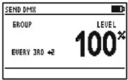
Use [CH+] and [CH-] buttons to select a group of channels. All groups are located below the channel 1.
Use the [+] , [-] , [0%] , [50%] and the [100%] buttons to set the level of a group of channels.
The available groups are shown below.


13 Send Options
When the XMT is in send mode, press the [OK] button to enter the special settings menu.
CLEAR ALL CHANNELS Set all channels to zero.
STORE SCENE Store the edited values to a scene.
LOAD SCENE Load a scene.
SHOW LEVEL AS Choose whether the level is displayed in percents, decimal or hexadecimal.
EDIT MODE Choose edit mode. Normal or direct.
REFRESH RATE Set the DMX refresh rate for the DMX transmitter.
13.1 CLEAR ALL CHANNELS
In send DMX Mode:
- Press [OK] to access the send options.
- Choose CLEAR ALL CHANNELS with the [UP] and the [DOWN] button.
- Press [OK] to confirm.
- Press [CANCEL] to exit the send options.
Because the CLEAR ALL CHANNELS item is at the top of the send options menu, pressing the [OK] button twice will clear all channels.
13.2 STORE SCENE
In send DMX mode:
- Press [OK] to access the send options.
- Choose STORE SCENE with the [UP] and the [DOWN] button.
- Press [OK] to access the list of scenes.
- Choose a scene with [UP] and [DOWN] buttons.
- Press [OK] to confirm.
- Press [CANCEL] twice to exit the send options.
Note: The scenes in receive DMX mode and in send DMX mode are shared. All 512 channels are stored into a scene. Storing to a scene overwrites the scene's previous content. The scenes can be combined to a sequence by using the sequence editor. See chapter SEQUENCE.
13.3 LOAD SCENE
In send DMX mode:
- Press [OK] to access the send options.
- Choose LOAD SCENE with [UP] and [DOWN] buttons.
- Press [OK] to access the list of scenes.
- Choose the scene with [UP] and [DOWN] buttons.
- Press [OK] to confirm.
- Press [CANCEL] twice to exit the send options.
All 512 channels of the scene are loaded.
13.4 SHOW LEVEL AS
In send DMX mode:
- Press [OK] to access the send options.
- Choose the SHOW LEVEL AS item with the [UP] or with the [DOWN] button.
- Press [OK] to change the level display format.
- Press [Cancel] to exit the send options.
The levels can be displayed in percents, in decimal or in hexadecimal.
13.5 EDIT MODE
In send DMX mode:
- Press [OK] to access the send options.
- Choose the EDIT MODE item with the [UP] / [DOWN] buttons.
- Press [OK] to change the edit mode. The edit mode can be NORMAL or DIRECT.
- Press [Cancel] to exit the send options.
Note: The edit mode setting does not affect groups of channels.
Normal Mode
In normal mode, the level of the current channel may be edited using the keypad. The adjusted level stays stored when the current channel is changed using the [CH+] and [CH-] keys.
Direct Mode
When changing the address in direct mode, the level of the previous address is cleared and the currently set level is assigned to the new address automatically.
To keep the level of an address when changing the current channel, it's possible to store its level using the [CANCEL] key. When the level of the current channel has been stored to a value that will stay when changing to another channel, "STORED" will be shown on the display.
DIRECT MODE![graph TD A["NORMAL MODE"] --> B["Ch+"] B --> C["+"] C --> D["CH+"] D --> E["+"] E --> F["CH+"] F --> G["+"]](/content/2026/07/1432132/images/b86e39d6faff0bec2100a6eb69ffbc09b9ffd049357682269d3f973be93d5fb2.jpg)

![graph TD A["+"] --> B["CH+"] B --> C["CH+"] C --> D["(toggle)"] D --> E["CH+"] E --> F["CH+"] F --> G["CH+"] G --> H["S"] style A fill:#fff,stroke:#000 style B fill:#fff,stroke:#000 style C fill:#fff,stroke:#000 style D fill:#fff,stroke:#000 style E fill:#fff,stroke:#000 style F fill:#fff,stroke:#00…](/content/2026/07/1432132/images/6a5187c8ff0f70f7e481ea3231e65fb3541bcf91883568e22eaac04a6891490d.jpg)
13.6 REFRESH RATE
In send DMX mode:
- Press [OK] to access the send options.
- Choose the REFRESH RATE item with the [UP]/[DOWN] buttons.
- Press [OK] to change the refresh rate.
- Press [Cancel] to exit the send options.
Available refresh rates are: 5, 10, 15, 20, 25, 30, 35, 40, 44 Hz (frames/sec).
14 CABLE TESTER
Press the [MODE] button and choose CABLE TESTER. Now, press the [OK] button to enter the cable tester mode.

Connect the cable to test to the DMX in and to the DMX out port. The XMT scans all pin connections automatically.


If the connection between a pair of pins is OK, it's indicated by a straight line connecting the pins.
Pin 2 is connected to pin 3. This is usually an error with DMX cables.
Pin 2 is shorted with pin 3. This is usually an error with DMX cables.
Pin 2 is not connected (broken circuit).
This is usually an error with DMX cables.
The speed of the scanning can be modified with the [0%], [50%], [100%] buttons.
15 CHANNEL TRACER
Press the [MODE] button and choose CHANNEL TRACER. Now, press the [OK] button to enter the channel tracer mode.

Connect a DMX source to the XMT's DMX in port.

The level of one channel is traced. The address of the current channel is displayed on the bottom left of the screen.
Use [CH+] and [CH-] buttons to change that address.
Use the [Cancel] button to stop and resume the tracing.
When stopped, a small cursor appears. The position of the cursor is displayed on the bottom right of the screen. The first value shows the DMX level and the second value shows the time at which this channel was received relative to the time at which the tracing was stopped.
Use [CH+] and [CH-] buttons to move the cursor.
Use [0], [50%] and [100%] buttons to zoom in and out.
Scroll up and down with [+] and [-] when zoomed in.

16 TIMINGS
Press the [MODE] button and choose TIMINGS. Now, press the [OK] button to enter the timings mode.

Connect a DMX source to the XMT's DMX in port.
| TIMINGS DMX IN | |
| DMX SIGNAL | OR |
| REFRESH RATE | 32 Hz |
| BREAK LENGTH | 192 US |
| MARK AFTER BREAK | 16 US |
| CHANNEL RECEIVED | 512 |
The XMT shows basic DMX-512 timings.
DMX SIGNAL
Shows if a DMX signal is OK or faulty.
REFRESH RATE
Shows the numbers of frames received per second.
BREAK LENGTH
Shows the length of the break in microseconds.
MARK AFTER BREAK
Shows the mark after break time in microseconds.
CHANNELS RECEIVED
Shows the number of channels received.
![graph LR A["CHANNEL 511"] --> B["BREAK"] C["CHANNEL 512"] --> B B --> D["MARK AFTER BREAK"] D --> E["STARTCODE"] E --> F["CHANNEL 1"] E --> G["CHANNEL 2"] E --> H["CHANNEL 3"] E --> I["CHANNEL 4"]](/content/2026/07/1432132/images/c3617e08835765080af0dafc239eb6ac72fb6367aaed9d9b83f2d6b4c6dc9709.jpg)
BREAK LENGTH MAB LENGTH
| USITT DMX-512/1986 |
| USITT DMX-512/1990 |
| ANSI E1.11-2004 |
| ≥88us | ≥4 us |
| ≥88us | ≥8 us |
| ≥92us | ≥12us |
Refresh Rates (indicative only)
| <1 frames per second not | compliant to standard |
| 1-10 frames per second very slow, compliant to standard but may cause problems with some equipment. | |
| 10-25 frames per second slow | |
| 25-44 frames per second typical for most equipment | |
| 44 frames per second maximum speed when sending all 512 channel. | |
| >44 frames per second only possible when sending less than 512 channel. Compliant to standard but may cause problems with some equipment. | |
Refer to ANSI E1.11 for more detailed information on DMX-512 timings. The accuracy of the XMT's timing measurement is approximately 1.5 microseconds.
17 SEQUENCE
Press the [MODE] button and choose SEQUENCE. Now, press the [OK] button to enter the sequence menu.
The sequence menu has three items.
EDIT SEQUENCE Create and edit the sequence.
PLAY SEQUENCE Play and stop the sequence, edit speed and fade time.
DELETE SEQUENCE Delete the sequence.
17.1 EDIT SEQUENCE
- Choose the EDIT SEQUENCE item with [UP]/[DOWN] buttons.
- Press [OK] to enter the sequence editor.
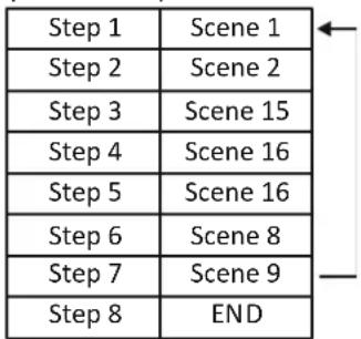
The sequence can be created with up to 100 steps using 32 scenes. The scenes can be recorded in receive and send mode.
Choose a step with the [CH+] and [CH-] buttons.
For each step, choose a scene with the [+] and [-] buttons.
Set the end of the sequence by choosing scene 0 (will be displayed as "end").

17.2 PLAY SEQUENCE
- Choose the PLAY SEQUENCE item with [UP]/[DOWN] buttons.
- Press [OK] to enter the replay mode.
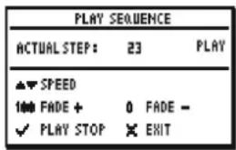
- Use the [OK] button to play and stop the sequence.
- Use the [+] button to increase and the [-] button to decrease the replay speed.
- Use [0] and [100%] to increase/decrease the fade time.
![graph LR A["Step 1 Step 2 Step 3 Step 4 Step 5 Step 6 Step 7"] --> B["←"] B --> C["←"] C --> D["→"]](/content/2026/07/1432132/images/5f92405c12c9867cd7cbe6b6102aec14c7ecce661b91c5641829d39c4e4556b4.jpg)
Speed Fade Time
17.3 DELETE SEQUENCE
- Choose the DELETE SEQUENCE item with [UP] / [DOWN] buttons and press [OK].
- Press [OK] again to confirm.
18 FIXTURES
Press the [MODE] button and choose FIXTURES. Now, press the [OK] button to enter the fixtures menu.
The fixtures menu has three items.
PATCH FIXTURES Patch fixtures to DMX addresses.
CLEAR PATCH: Clears the entire patch.
EDIT FIXTURES: Edit fixture definitions.
18.1 PATCH FIXTURES
- Choose the PATCH FIXTURES item using the [UP] / [DOWN] buttons.
- Press [OK] to enter the fixture patch editor. A list containing the defined fixture types appears.
- Select a fixture type with the [+] and [-] buttons, and press [OK].

ID: The fixture ID. It will be incremented automatically.
FIXTURE: Name of the fixture type.
ADDRESS: The patch address for the fixture.
The XMT proposes the next free DMX address as the patch address. This address can be changed with the [CH+] and [CH-] buttons.
Press [OK] to patch the device.

If a fixture is patched, the receive DMX mode and the send DMX mode will show information about the current channel on the bottom of the screen.
18.2 EDIT FIXTURES
The fixture types can be created and modified on the XMT itself or more conveniently with the XMT Fixture Library Editor on a computer.
- Choose the EDIT FIXTURES item with [UP] or [DOWN] button.
- Press [OK] to enter the fixture type editor. The entire patch will be cleared.
- Press [OK] to confirm.
- Use [+] and [-] buttons to edit a fixture or CREATE NEW FIXTURE to create a new one.
NAME Name of the fixture.
NUMBER OF CH Number of DMX channels used by this fixture.
CHANNEL DEF Definition of the channel description.
DELETE FIXTURE Delete the fixture definition.
Name
- Use [+] and [-] buttons to select NAME.
- Select the cursor position by pressing [CH +] or [CH-] and change the character at the cursor position with [+] and [-].
- Pressing [0] will set the character to a blank space.
- When done press [OK] and the name will be saved. Press [CANCEL] keep the old name.
Number of channels
- Use [+] and [-] buttons to select NUMBER OF CHANNELS.
- Use [+] and [-] to set the number of channels for the fixture
Channel definition
- Use the [+] and [-] buttons to select CHANNEL DEF. A list with all channels of the fixture appears.
- Use the [+] and [-] buttons to select the channel.
- Press [OK] to edit the channel description.
- Select the cursor position by pressing [CH+] or [CH-] and change the character at the cursor position with [+] and [-].
- Pressing [0] will set the character to a blank space.
- When done press [OK] and the name will be saved. Press [CANCEL] to keep the old name.
19 Connect to PC
The XMT PC Software can be downloaded from the Swisson website. www.swisson.com
• Install the XMT PC Software before connecting the XMT to the PC.
- Connect the XMT to the PC with a USB cable.
- Press the [MODE] button and choose PC Connection. Press now the [OK] button to enter the PC connection mode.

PC XMT-120A / XMT-350
20 OPTIONS
Press the [MODE] button and choose OPTIONS. Now, press the [OK] button to enter the options menu.
The options menu has the following items.
ENTER NAME: Personalize your XMT.
LOAD DEFAULT OPTIONS: Load the factory defaults.
SHOW BINARY ADDRESS: Show a binary representation of the address in DMX receive mode and DMX send mode.
SHOW MIN MAX: Show minimum and maximum values in DMX receive mode.
CONTRAST: Contrast setting for the LCD display.
POWER SETTINGS: Configure power settings of the XMT.
FIRMWARE UPDATE: Mode to perform firmware update of the XMT.
20.1 ENTER NAME
Choose the ENTER NAME item with the [UP] or [DOWN] button.
Press [OK] to enter the name dialog.
Select the cursor position by pressing [CH+] or [CH-] and change the character at the cursor position using [+] and [-].
Pressing [0] will set the character to a blank space.
When done, press [OK] and the name will be saved. Press [CANCEL] to keep the old name.

The name is displayed on the boot screen every time the XMT is turned on.
20.2 LOAD DEFAULT OPTIONS
- Choose the LOAD DEFAULT OPTIONS item with [UP]/[DOWN] buttons.
- Press [OK] to load the factory defaults.
20.3 SHOW BINARY ADDRESS
- Choose the SHOW BINARY ADDRESS item with [UP] or [DOWN] buttons.
- Press [OK] to select between NO, YES 0 and YES 1.
NO: Binary address display is disabled.
YES 0: Binary address display is enabled. Address is displayed as 0-based binary.
Address 1 to 512 are mapped to the range of 0 to 511 for binary display. This is useful for 9-bit dip switches on DMX fixtures.
YES 1: Binary address display is enabled. The range of the binary addresses is 1 to 512.

If enabled, the binary representation of the address is displayed below the address in receive DMX mode and in send DMX mode.
20.4 SHOW MIN AND MAX VALUES
- Choose the SHOW MIN-MAX item with [UP] or [DOWN] buttons.
- Press [OK] to toggle between YES and NO.

If enabled, the min and max values of a level are displayed below the level in receive DMX mode.
20.5 CONTRAST
- Choose the CONTRAST item with the [UP]/[DOWN] buttons.
- Press [OK] to enter the contrast editor.
- Use the [+] and [-] buttons to modify the contrast.
20.6 POWER SETTINGS
- Choose the POWER SETTINGS item using the [UP]/[DOWN] buttons.
- Press [OK] to enter the power settings menu.
The power settings menu has three items:
BACKLIGHT BRIGHTNESS: Set the brightness of the backlight.
BACKLIGHT DURATION: Set the duration of the backlight.
TURN OFF IF IDLE: Automatic turn-off time for the XMT when battery operated.
- Choose the BACKLIGHT BRIGHTNESS item with the [UP] or [DOWN] buttons.
- Press [OK] to change the backlight brightness from 10% to 100% in steps of 10%.
BACKLIGHT DURATION
- Choose the BACKLIGHT DURATION item with the [UP] or [DOWN] buttons.
- Press [OK] to change the backlight duration from 10 seconds to 2 minutes.
The LED backlight of the LCD screen uses a lot of energy. Try to set the backlight as low as possible and the duration of the backlight as short as necessary to save battery life.
TURN OFF IF IDLE
- Choose the TURN OFF IF IDLE item with the [UP] or [DOWN] buttons.
- Press [OK] to change the time after which the XMT will turn off automatically when battery operated.
Possible values are: NO = stays on, 1min, 2min, 3min, 5min, 10min. The time is reset to zero whenever a button on the keypad is pressed.
The XMT will not turn off automatically when it is USB powered.
20.7 FIRMWARE UPDATE
- Choose the FIRMWARE UPDATE item with the [UP]/[DOWN] buttons.
- Press [OK] to enter the firmware update mode.
This feature does the same as PC CONNECTION. See section PC CONNECTION.
21 RDM Controller (XMT-350 Only)
Press the [MODE] button and choose RDM. Now, press the [OK] button to start the RDM controller.
21.1 RDM Discovery
The XMT performs a full discovery when starting the RDM controller. During discovery, the XMT searches for connected RDM devices. The discovery can be aborted using the [CANCEL] button.

21.2 RDM Main Screen
After the full discovery, the main screen of the RDM controller is displayed. An incremental discovery is running in the background to detect RDM fixtures connected once the full discovery is completed.
The main screen shows a list of the RDM devices discovered.

The device description and the DMX address are displayed for all found RDM devices:
MAC 101 329
The currently selected device is inverted:
MAC 101 329
A small rotating animation appears when the connection to an RDM device is lost:
MAC 101
N/A is displayed instead of the DMX address when the RDM device does not have a DMX address. Typically, devices such as DMX splitters have no DMX address:
DMX/RDM SPLITTER H/A
Each RDM device has an identify mode. A blinking dot shows which device is currently in this mode. By default, the XMT-350 puts the currently highlighted device into identify mode. This behavior can be disabled. See section 21.5 RDM Options on page 22.
MAC 101 329
When an RDM responder is found, the UID is shown until more detailed information is available.
(4567AC5CD32B)
On the upper right corner, the number of currently connected devices and the total number of detected devices.
42,44
21.3 RDM Device Details
Use the [+]/[-] buttons to select an RDM device. Press OK to enter the details screen of the RDM device.
Parameters with a small arrow on the left can be edited by pressing [OK].
The following parameters are currently supported by the XMT-350:
LABEL: Editing is currently not supported by the XMT-350.
MODEL: Model is a fixed name set by manufacturer.
MAN.: Manufacturer of the RDM device.
DMX START ADDRESS: Current DMX address of the RDM device.
DMX PERSONALITY: Current personality (mode). Press [OK] to change the personality.
DMX SLOTS: Number of slots used by the RDM responder in the current DMX personality. (Number of DMX channels)
MOVING LIGHT MENU:
PAN INVERT: Pan invert mode of the RDM device. Toggle on or off with [OK].
TILT INVERT: Tilt invert mode of the RDM device. Toggle on or off with [OK].
PAN TILT SWAP: Pan/tilt swap mode of the RDM device. Toggle on or off with [OK].
DEVICE DETAILS:
RESET:
WARM RESET: Press [OK] to start a warm reset of the RDM device.
COLD RESET: Press [OK] to start a cold reset of the RDM device.
DEVICE HOURS: Operating hours of the RDM device.
LAMP MENU:
LAMP ON MODE: Press [OK] to change the lamp on mode.
OFF: Lamp stays off until directly instructed to strike.
DMX: Lamp strikes upon receiving a DMX512 signal.
ON: Lamp strikes automatically at power-up.
AFTER CALIBRATION: Lamp strikes after calibration or homing procedure.
LAMP STATE: Status of the lamp. OFF, ON, STRIKE, STANDBY, NOT PRESENT, ERROR.
LAMP HOURS: Operating hours of the lamp.
LAMP STRIKES: Number of strikes of the lamp.
SENSOR MENU: The sensor menu lists the sensors and their values reported by the RDM device.
UID: The RDM unique identifier of the RDM device.
Newer firmware versions may support additional undocumented parameters.
Parameters not supported by the RDM responder will be displayed as N/A. Some editable parameters may be “read only” with some RDM responders.
21.4 RDM Patch DMX Addresses
Use [CH+] or [CH-] to enable patch mode.

Select a device with the [+]/[-] buttons and press [OK] to patch / readdress the device. A patch dialog will show up. The XMT-350 proposes a DMX address. This address can be changed manually. Use the [+] and [-] buttons to change the proposed DMX address. Press [OK] to patch the device or [CANCEL] to abort.

A device which has not been patched yet is displayed with the DMX address in brackets. As soon as the device is patched, the brackets disappear.
MAC 101 (222)
The brackets are a guide for the user to know which devices have already been readdressed (patched).
The first item on the list is ">RESTART PATCH".
Select this item to restart the patch. In this case, all devices will be marked with the brackets.
▶RESTART PATCH
The devices in the list which are marked as "not patched" with the brackets are sorted by UID (unique identifier). All patched devices are sorted by DMX address. The sorting can be disabled. See Chapter 21.5 RDM Options on page 22.
21.5 RDM Options
Use [CH+] or [CH-] to enter the RDM options.
The following options are available:
IDENTIFY: Enable and disable identify mode.
SORT PATCH TAB.: Enable and disable the sorting of the patch table.
22 Additional Technical Information
22.1 Block Diagram XMT Interfaces
![graph LR A["PROTECTION"] --> B["CABLE TESTER"] A --> C["RECEIVER"] A --> D["TRANSMITTER"] A --> E["CABLE TESTER/DMX INDMX OUT"] B --> F["2"] C --> G["3"] D --> H["4"] E --> I["5"] F --> J["1"] G --> K["2"] H --> L["3"] I --> M["4"] J --> N["5"] K --> O["6"] L --> P["7"] M --> Q["8"] N --> R["9"] O -…](/content/2026/07/1432132/images/c4f5e0011446c6b4369df106e9050b7ab5d7351f3ed5959aaaccffc2a0dc87ec.jpg)
22.2 Ground Topologies
 Is the XMT battery operated, the DMX out port is an isolated transmitter. Is the XMT battery operated, the DMX out port is an isolated transmitter. |  Is the XMT connected to a PC, the DMX out port might be a ground referenced transmitter when the USB is grounded. Is the XMT connected to a PC, the DMX out port might be a ground referenced transmitter when the USB is grounded. |
 Is the XMT battery operated, the DMX in port is an isolated receiver. Is the XMT battery operated, the DMX in port is an isolated receiver. |  Is the XMT connected to a PC, the DMX in port might be a ground referenced receiver when the USB is grounded. Is the XMT connected to a PC, the DMX in port might be a ground referenced receiver when the USB is grounded. |
 Is the XMT connected to a DMX controller with a ground referenced transmitter, the XMT DMX out port is a ground referenced transmitter. Is the XMT connected to a DMX controller with a ground referenced transmitter, the XMT DMX out port is a ground referenced transmitter. |  Is the XMT connected to a USB charger, the DMX in port might be an isolated transmitter when the USB is not grounded. Is the XMT connected to a USB charger, the DMX in port might be an isolated transmitter when the USB is not grounded. |
23 Safety Information
Consider the following notes absolutely when you set up, connect and use the XMT.
This product is not for household use. Read this manual before operating the device, follow the safety precautions and observe all warnings in this manual.
Use this device only in accordance with local laws and regulations.
- Do not expose the device to rain or moisture.
- Do not operate the device if any cover or component is missing, damaged, or deformed. Refer any service operation not described in this manual to Swisson.
- Provide unrestricted airflow around the device.
- Do not operate the device if the ambient temperature exceeds 55°C (131°F).
- Do not modify the device in any way not described in this manual or install other than genuine Swisson parts.
- Do not use the device in areas where it is exposed to direct sunlight.
- Do not use the device in areas that are considered to be 'highly combustible'.
24 Technical Data
Hardware
Display type.....LCD
Display back light......LED green
Display resolution....128x64 pixel
FLASH memory....16MBytes
DMX in port......Neutrik 5-pin male connector
DMX out port......Neutrik 5-pin female connector
DMX ports electrical standard....ANSI E1.11 / ANSI E1.20
USB port....Micro USB B type
Battery....9V block battery
USB Power consumption.....150mA max
Use of rechargeable battery.....Yes
Battery recharge......No
Cable tester....5-pin, open circuit, short circuit, wrong wiring
DMX in termination....120 Ohm, permanent (except cable tester)
DMX out termination....RDM bias network, RC-termination
Operating temperature....0°C to +45°C / 32°F to 113°F
Dimensions....119mm x 71mm x 46mm / 4.7" x 2.8" x 1.8"
Weight....400g / 0.88 lbs
Firmware (XMT-120A Version 1.15, XMT-350 Version 1.02)
Received DMX channels....512
Transmitted DMX channels....512
Refresh rates....5, 10, 15, 20, 25, 30, 35, 44 frames per second
Transmitter break length.....140-150 microseconds / not configurable
Transmitter MAB length....28-32 microseconds / not configurable
Timing measurement.....Frames per second / Break / MAB
Display formats: Percent, Decimal, Hexadecimal
DMX scene storage: 32 scenes, 512 channels each
Number of sequences: 1
Steps in sequence: 99
Number of fixture types: 100
Channels per fixture: 45
RDM controller: XMT-120A: NO / XMT-350: YES

- INTRODUCTION
- APPLICATIONS
- TYPICAL APPLICATION
- UNPACKING
- OVERVIEW
- BACKLIGHT
- POWER
- OK [OK]
- CANCEL [CANCEL]
- TOGGLE
- CHANNEL + [RIGHT]
- CHANNEL - [LEFT]
- VALUE + [UP]
- NAVIGATE
- VALUE - [DOWN]
- CHANNEL TO
- CHANNEL AT
- MODE
- DISPLAY
- MICRO-USB SOCKET
- DMX IN
- DMX OUT
- BATTERY
- THE BATTERY IS NOT CHARGED BY THE XMT
- USB PORT
- CHOOSE OPERATING MODES
- RECEIVE DMX
- RECEIVER OPTIONS
- STORE SCENE
- SHOW LEVEL AS
- DISPLAY MODE
- ADDRESSES
- SEND DMX
- SET LEVEL OF ALL CHANNELS
- SET LEVEL OF GROUP OF CHANNELS (LED)
- SEND OPTIONS
- CLEAR ALL CHANNELS
- LOAD SCENE
- EDIT MODE
- NORMAL MODE
- DIRECT MODE
- REFRESH RATE
- CABLE TESTER
- CHANNEL TRACER
- TIMINGS
- SEQUENCE
- EDIT SEQUENCE
- PLAY SEQUENCE
- DELETE SEQUENCE
- FIXTURES
- PATCH FIXTURES
- EDIT FIXTURES
- NAME
- NUMBER OF CHANNELS
- CHANNEL DEFINITION
- CONNECT TO PC
- OPTIONS
- ENTER NAME
- LOAD DEFAULT OPTIONS
- SHOW BINARY ADDRESS
- SHOW MIN AND MAX VALUES
- CONTRAST
- POWER SETTINGS
- BACKLIGHT DURATION
- TURN OFF IF IDLE
- FIRMWARE UPDATE
- RDM CONTROLLER (XMT-350 ONLY)
- RDM DISCOVERY
- RDM MAIN SCREEN
- RDM DEVICE DETAILS
- MOVING LIGHT MENU
- DEVICE DETAILS
- LAMP MENU
- RDM PATCH DMX ADDRESSES
- RDM OPTIONS
- ADDITIONAL TECHNICAL INFORMATION
- BLOCK DIAGRAM XMT INTERFACES
- GROUND TOPOLOGIES
- SAFETY INFORMATION
- TECHNICAL DATA
- HARDWARE
- FIRMWARE (XMT-120A VERSION 1.15, XMT-350 VERSION 1.02)
Brand : Swisson
Model : XMT-120A
Category : Lighting