
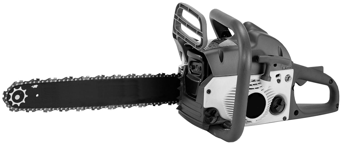
TB4016CC - Gas chainsaw MTD - Free user manual and instructions
Find the device manual for free TB4016CC MTD in PDF.


| Product Type | Gas chainsaw |
| Brand | MTD |
| Model | TB4016CC |
| Displacement (estimated) | 40 cc |
| Guide bar length | 40 cm (16 inches) |
| Chain | 54 drive links (DL) |
| Oil/gas mixture ratio | 40:1 |
| Fuel tank capacity (estimated) | 0.5 L |
| Chain oil tank capacity (estimated) | 0.2 L |
| Weight (estimated) | 5.5 kg |
| Starting system | Spring Assist Starting™ |
| Chain brake | Chain Brake® (inertia brake) |
| Lubrication | Automatic |
| Safety features | Chain brake, safety lock, chain catcher, spark arrestor, stop switch |
| Air filter | Washable with soapy water |
| Spark plug | Gap 0.635 mm (0.025 in) |
| Spark arrestor | Present, screen to inspect and replace if necessary |
| Fuel type | Unleaded gasoline mixed with 2-cycle oil (40:1) |
| Application | Wood cutting (felling, limbing, bucking) |
Frequently Asked Questions - TB4016CC MTD
User questions about TB4016CC MTD
0 question about this device. Answer the ones you know or ask your own.
Ask a new question about this device
Download the instructions for your Gas chainsaw in PDF format for free! Find your manual TB4016CC - MTD and take your electronic device back in hand. On this page are published all the documents necessary for the use of your device. TB4016CC by MTD.
USER MANUAL TB4016CC MTD
2-Cycle Gas Chain saws
Model TB4016CC
&
Model TB4218CC
This product has been tested at a computed kickback angle (CKA) and conforms to ANSI B175.1-2000, Annex C. CAN/CSA-Z62.1-03
WARNING · PLEASE READ
Beware of kickback. Hold chain saw firmly with both hands when using. For your own safety, please read and follow the safety precautions in this manual before attempting to operate your chain saw. Improper use can cause serious injury.
SAVE THESE INSTRUCTIONS
DO NOT THROW AWAY
INTRODUCTION
THANK YOU
Thank you for buying this quality product. This modern outdoor power tool will provide many hours of useful service. You will find it to be a great labor-saving device. This operator's manual provides you with easy-to-understand operating instructions. Read the whole manual and follow all the instructions to keep your new outdoor power tool in top operating condition.
PRODUCT REFERENCES, ILLUSTRATIONS AND SPECIFICATIONS
All information, illustrations, and specifications in this manual are based on the latest product information available at the time of printing. We reserve the right to make changes at any time without notice.
Copyright© 2004 MTD SOUTHWEST INC, All Rights Reserved.
SERVICE INFORMATION
Service on this unit both within and after the warranty period should be performed only by an authorized and approved service dealer.
For service call 1-800-520-5520 to obtain a list of authorized service dealers near you. For more details about your unit, visit our website at www.troybilt.com.
DO NOT RETURN THE UNIT TO THE RETAILER. PROOF OF PURCHASE WILL BE REQUIRED FOR WARRANTY SERVICE.
Before beginning, locate the unit's model plate. It lists the model and serial numbers of your unit. Refer to the sample plate below and copy the information for future reference.
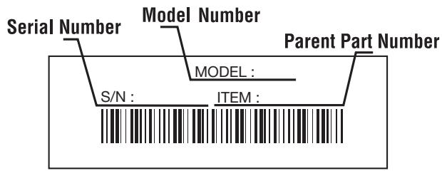
Copy the model and parent part number here:
Copy the serial number here:
Make sure you carefully read and understand this manual before starting or operating this equipment.
THIS PRODUCT IS COVERED BY ONE OR MORE U.S. PATENTS. OTHER PATENTS PENDING.
TABLE OF CONTENTS
Service Information 2
Rules for Safe Operation 3
Know Your Unit 7
Oil and Fuel Information 9
Starting/Stopping Instructions 10
Operating Instructions 11
Maintenance and Repair Instructions 13
Troubleshooting Chart 20
Warranty Information 22
Parts List .E23
SPARK ARRESTOR NOTE
NOTE: For users on U.S. Forest Land and in the states of California, Maine, Oregon and Washington. All U.S. Forest Land and the state of California (Public Resources Codes 4442 and 4443), Oregon and Washington require, by law that certain internal combustion engines operated on forest brush and/or grass-covered areas be equipped with a spark arrester, maintained in effective working order, or the engine be constructed, equipped and maintained for the prevention of fire. Check with your state or local authorities for regulations pertaining to these requirements. Failure to follow these requirements could subject you to liability or a fine. This unit is factory equipped with a spark arrester. If it requires replacement, ask your LOCAL SERVICE DEALER to install the Spark Arrestor Kit.
CALIFORNIA PROPOSITION 65 WARNING

The purpose of safety symbols is to attract your attention to possible dangers. The safety symbols, and their explanations, deserve your careful attention and understanding. The safety warnings do not by themselves eliminate any danger. The instructions or warnings they give are not substitutes for proper accident prevention measures.
SYMBOL MEANING

SAFETY ALERT: Indicates danger, warning or caution. Attention is required in order to avoid serious personal injury. May be used in conjunction with other symbols or pictographs.
NOTE: Advises you of information or instructions vital to the operation or maintenance of the equipment.
Read the Operator's Manual(s) and follow all warnings and safety instructions.
Failure to do so can result in serious injury to the operator and/or bystanders.
FOR QUESTIONS, CALL 1-800-520-5520
SYMBOL MEANING

DANGER: Failure to obey a safety warning will result in serious injury to yourself or to others. Always follow the safety precautions to reduce the risk of fire, electric shock and personal injury.

WARNING: Failure to obey a safety warning can result in injury to yourself and others. Always follow the safety precautions to reduce the risk of fire, electric shock and personal injury.

CAUTION: Failure to obey a safety warning may result in property damage or personal injury to yourself or to others. Always follow the safety precautions to reduce the risk of fire, electric shock and personal injury.
- IMPORTANT SAFETY INSTRUCTIONS
READ ALL INSTRUCTIONS BEFORE OPERATING

WARNING: If correctly used, the chain saw is a quick, easy to handle and efficient tool; if used improperly or without the due precautions it could become a dangerous tool. For pleasant and safe work, always strictly comply with the safety rules that follow and throughout this manual.
- Read the instructions carefully. Be familiar with the controls and proper use of the unit.
- Do not operate this unit when tired, ill or under the influence of alcohol, drugs or medication.
- Only responsible individuals who are familiar with the instructions may operate the chain saw (no one under the age of 16). Provide parental supervision at all times.
- Inspect the unit before use. Replace damaged parts. Check for fuel leaks. Make sure all fasteners are in place and secure. Replace parts that are cracked, chipped or damaged in any way.
- Know the controls and know how to stop the chain saw quickly.
- Carry the chain saw with the engine stopped, the guide bar and saw chain to the rear, and the muffler away from your body.
- When transporting your chain saw, use the appropriate guide-bar scabbard (sheath).
WHILE OPERATING
- Keep all parts of your body away from the chain when the engine is running.
- Never start or run the unit inside a closed room or building. Breathing exhaust fumes can kill. Operate this unit only in a well ventilated outdoor area.
- Wear safety glasses or goggles that are marked as meeting ANSI Z87.1-1989 standards. Also wear ear/hearing protection when operating this unit. Wear a face or dust mask if the operation is dusty. Long sleeve shirts are recommended.
- Wear heavy, long pants, boots or safety footwear and protective gloves. Do not wear loose clothing, jewelry, short pants, sandals or go barefoot. Secure hair above shoulder level.
- Use the unit only in daylight or good artificial light.
- Avoid accidental starting. Be in the starting position whenever pulling the starter rope. The operator and unit must be in a stable position while starting. See Starting/Stopping Instructions.
- Before you start the engine, make sure that the saw's chain is not contacting anything. Do not cut near electrical cables or power lines.
- Keep all parts of your body away from the chain when the engine is running.
- Do not start cutting until you have a clear work area, secure footing, and a planned retreat path from the falling tree.
- Do not operate a chain saw that is damaged, improperly adjusted, or not completely and securely assembled. Be sure that the saw's chain stops moving when the throttle control trigger is released.
- Shut off the engine before setting the chain saw down.
- Use extreme caution when cutting small-sized brush and saplings because slender material may catch the chain saw and whip towards you or pull you off balance.
- When cutting a limb that is under tension, be alert for springback so that you will not be struck when the tension in the wood fibers is released
- Do not cut through nails, rods in the tree, railroad ties or pallets. Inspect a tree that you are going to cut for foreign objects that could cause injury or damage to your chain saw.
- After striking a foreign object, stop the engine and thoroughly inspect for damage. Repair as necessary.
- Keep the handles dry, clean and free of the oil/fuel mixture
- We do not recommend using the chain saw in a tree or on a ladder.
- All chain saw service, other than the items listed in this instruction manual maintenance instructions, should be performed by competent chain saw service personnel.
- Use the right tool. Only use this chain saw for its intended purpose, to cut wood.
- Do not overreach. Always keep proper footing and balance.
- Always hold the unit with both hands when operating. Keep a firm grip on all handles or grips.
- Apply chain brake prior to any repositioning of the operator in the cutting area. As an additional safety precaution, apply the chain brake prior to setting down the saw.
- Never touch the chain or attempt to service the saw while the engine is running. Make sure all moving parts have stopped. Allow the chain saw to cool, as the chain can be hot.
- Check the bar and chain at frequent intervals for proper adjustment. Make sure the bar and chain are properly tightened and sharpened. Visually inspect for damage. Repair any damage before restarting or operating the chain saw.
KICKBACK SAFETY PRECAUTIONS

WARNING: KICKBACK may occur when the nose or tip of the guide bar touches an object, or when the wood closes in and pinches the saw chain in the cut. Tip contact in some cases may cause a lightning-fast reverse reaction, kicking the guide bar up and back towards the operator. Pinching the saw chain along the top of the guide bar may push the guide bar rapidly back toward the operator. Either of these reactions may cause you to lose control of the saw, which could result in serious personal injury. Do not rely exclusively upon the safety devices built into your saw. As a chain saw user, you should take several steps to keep your cutting jobs free from accident or injury.
- With a basic understanding of kickback, you can reduce or eliminate the element of surprise. Sudden surprise contributes to accidents. Be alert to the potential for kickback at all times.
- Keep a good firm grip on the saw with both hands, the right hand on the rear handle and the left hand on the front handle, when the engine is running. Use a firm grip with thumbs and fingers encircling the chain saw handles. A firm grip will help you reduce kickback and maintain control of the saw. Don't let go.
- Make sure that the area in which you are cutting is free from obstructions. Do not let the nose of the guide bar contact a log, branch, fence, or any other obstruction that could be hit while you are operating the saw.
- Always cut with the engine running at full speed. Fully squeeze the throttle trigger and maintain a steady cutting speed.
- Use only the correct original equipment manufacturer replacement bars, chains and other parts and accessories. These are available from your authorized service dealer. Use of any unauthorized parts or accessories could lead to serious injury to the user, or damage to the unit, and will void your warranty.
- Follow the manufacturer's sharpening and maintenance instructions for the saw chain.
- Use only the replacement guide bars and low kickback chains specified for your saw to avoid injury.
OTHER SAFETY PRECAUTIONS
- Do not operate a chain saw with one hand! Serious injury to the operator, helpers, bystanders, or any combination of these persons may result from one-handed operation. A chain saw is intended for two-handed use.
- Do not operate a chain saw if you are fatigued.
- Use safety footwear; snug-fitted clothing; protective gloves; and eye, hearing, and head protection devices.
- Do not allow other persons to be near the chain saw when starting or cutting with the chain saw. Keep bystanders and animals out of the work area.
- Do not remove, damage or de-activate any of the safety devices. Never use a damaged, modified, or improperly repaired or assembled chain saw. Check their proper operation regularly. Only use bars and chains of the length indicated in the table herein.
- Never carry out operations or repairs on your own that are other than routine maintenance. For information, contact specialized and authorized workshops only.
- If your chain saw is no longer usable, dispose of it properly without damaging the environment by handing it in to your local dealer who will arrange for its correct disposal.
- Use caution when felling a tree. Make sure you have planned an escape path when felling, and keep all bystanders away.
- Be alert; stop the machine if anyone enters the cutting area, which is usually 3 to 4 feet around the operator.
- Use caution when working in a crew to avoid injury to a fellow worker who may enter the cutting area.
- Only loan your saw to experienced users who are completely familiar with saw operation and correct use. Give other users this manual, which they should read before using the saw. Provide them the operating instructions.
- Shut off the engine before setting down the saw. Do not leave the engine running unattended.
- Never store the unit, with fuel in the tank, inside a building where fumes may reach an open flame or spark.
-
Allow the engine to cool before storing or transporting the chain saw over long distances. For example, let the engine cool before placing the chain saw in an automobile. Also, be sure to secure the unit while transporting.
-
Store the unit in a dry area, locked up, located up high and located out of the reach of children to prevent unauthorized use or damage.
- Never douse or squirt the unit with water or any other liquid. Keep handles dry, clean and free from debris. Clean after each use.
- Keep these instructions. Refer to them often and use them to instruct other users. If you loan someone this unit, also loan them these instructions.
- Do not use the unit in the rain, in a storm or in inclement weather. Wait until the storm danger has passed before operation of this product.
FUEL SAFETY

WARNING: Gasoline is highly flammable, and its vapors can explode if ignited. Take the following precautions:
- Store fuel only in containers specifically designed and approved for the storage of such materials.
- Always stop the engine and allow it to cool before filling the fuel tank. Never remove the cap of the fuel tank, or add fuel, when the engine is hot. Never operate the unit without the fuel cap securely in place. Loosen the fuel tank cap slowly to relieve any pressure in the tank.
- Add fuel in a clean, well-ventilated outdoor area where there are no sparks or flames. Slowly remove the fuel cap only after stopping engine. Do not smoke while fueling or mixing fuel. Wipe up any spilled fuel from the unit immediately.
- Avoid creating a source of ignition for spilled fuel. Do not start the engine until fuel vapors dissipate.
- Move the unit at least 30 feet (9.1 m) from the fueling source and site before starting the engine. Do not smoke. Keep sparks and open flames away from the area while adding fuel or operating the unit.
SAVE THESE INSTRUCTIONS
SAFETY AND INTERNATIONAL SYMBOLS
This operator's manual describes safety and international symbols and pictographs that may appear on this product. Read the operator's manual for complete safety, assembly, operating and maintenance and repair information.
SYMBOL MEANING

- SAFETY ALERT SYMBOL
Indicates danger, warning, or caution. May be used in conjunction with other symbols or pictographs.

WARNING - READ OPERATOR'S MANUAL
Read the Operator's Manual(s) and follow all warnings and safety instructions. Failure to do so can result in serious injury to the operator and/or bystanders.
SYMBOL MEANING

ON/OFF CONTROL
ON/START/RUN

ON/OFF CONTROL
OFF OR STOP

- WEAR EYE, HEARING AND HARDHAT PROTECTION
WARNING: Thrown objects and loud noise can cause severe eye injury and hearing loss. Wear eye protection meeting ANSI Z87.1-1989 standards and ear protection when operating this unit. Wear a hard hat. Use a full face shield when needed.
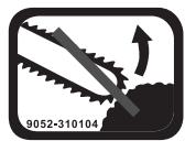
GUIDE BAR WARNING:
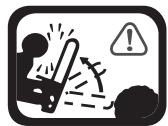
Contact of the guide bar tip with any object should be avoided. Tip contact may cause the guide bar to move suddenly upward and backward, which may cause serious injury.
- UNLEADED FUEL
Always use clean, fresh unleaded fuel.
USE BOTH HANDS
Always use both hands while operating the chain saw. Never use only one hand to operate the saw.

OIL
Refer to operator's manual for the proper type of oil.
Avoid bar nose contact.
Numbers preceding the descriptions correspond with the numbers above to help you locate the safety feature.
2 LOW KICKBACK SAW CHAIN helps significantly reduce kickback, or the intensity of kickback, due to specially designed depth gauges and guard links.
4 SPARK ARRESTER SCREEN retains carbon and other flammable particles over 0.023 inches (0.6mm) in size from engine exhaust flow. Compliance with local, state and federal laws and/or regulations governing the use of a spark arrester screen is the user's responsibility. See Safety Precautions for additional information.
5 CHAIN BRAKE® LEVER / HAND GUARD protects the operator's left hand in the event it slips off the front handle while saw is running.
5 CHAIN BRAKE® is a safety feature designed to reduce the possibility of injury due to kickback by stopping a moving saw chain in milliseconds. It is activated by the CHAIN BRAKE® lever.
10 STOP SWITCH immediately stops the engine when tripped. Stop switch must be pushed to ON position to start or restart engine.
11 SAFETY LATCH prevents accidental acceleration of the engine. Throttle trigger (19) cannot be squeezed unless the safety latch is depressed.
20 CHAIN CATCHER reduces the danger of injury in the event saw chain breaks or derails during operation. The chain catcher is designed to intercept a whipping chain.
WARNING: Kickback can lead to dangerous loss of control of the chain saw and result in serious or fatal injury to the saw operator or to anyone standing close by. Always be alert. Rotational kickback and pinch-kickback are major chain saw operational dangers and the leading cause of most accidents.
Beware of:
Rotational Kickback
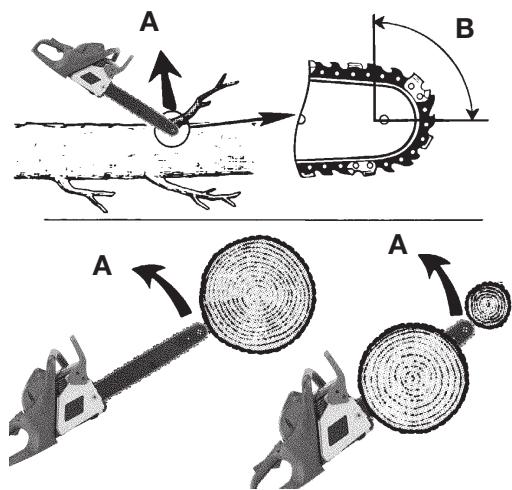
Fig. 1
A = Kickback path
B = Kickback reaction zone
KICKBACK SPECIFICS
Beware of:
Pinch Kickback
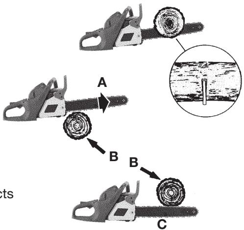
Fig. 2
A = Pull
B = Solid objects
C = Push
KICKBACK may occur when the NOSE or TIP of the guide bar touches an object, or when wood closes in and pinches the saw chain in the cut.
Tip contact in some cases may cause a lightning-fast reverse reaction, kicking the guide bar up and back toward the operator.
PINCHING the saw chain along the BOTTOM of the guide bar may PULL the saw forward away from the operator. PINCHING the saw chain along the TOP of the guide bar may PUSH the guide bar rapidly back toward the operator.
Any of these reactions may cause you to lose control of the saw, which could result in serious personal injury.
OIL AND FUEL INFORMATION
OIL AND FUEL MIXING INSTRUCTIONS
Old and/or improperly mixed fuel are the main reasons for the unit not running properly. Be sure to use fresh, clean unleaded fuel. Follow the instructions carefully for the proper fuel/oil mixture.
Definition of Blended Fuels
Today's fuels are often a blend of gasoline and oxygenates such as ethanol, methanol, or MTBE (ether). Alcohol-blended fuel absorbs water. As little as 1% water in the fuel can make fuel and oil separate. It forms acids when stored. When using alcohol-blended fuel, use fresh fuel (less than 60 days old).
Using Blended Fuels
If you choose to use a blended fuel, or its use is unavoidable, follow recommended precautions:
- Always use the fresh fuel mix explained in your operator's manual
- Always agitate the fuel mix before fueling the unit
- Drain the tank and run the engine dry before storing the unit
Using Fuel Additives
The bottle of 2-cycle oil that came with your unit contains a fuel additive which will help inhibit corrosion and minimize the formation of gum deposits. It is recommended that you use our 2-cycle oil with this unit. If unavailable, use a good 2-cycle oil designed for air-cooled engines along with a fuel additive, such as STA-BIL® Gas Stabilizer or an equivalent. Add 0.8 oz. (23 ml.) of fuel additive per gallon of fuel according to the instructions on the container. NEVER add fuel additives directly to the unit's fuel tank.

CAUTION: For proper engine operation and maximum reliability, pay strict attention to the oil and fuel mixing instructions on the 2-cycle oil container. Using improperly mixed fuel can severely damage the engine.
Thoroughly mix the proper ratio of 2-cycle engine oil with unleaded gasoline in a separate fuel can. Use a 40:1 fuel/oil ratio. Do not mix them directly in the engine fuel tank. See the table below for specific gas and oil mixing ratios.
NOTE: One gallon (3.8 liters) of unleaded gasoline mixed with one 3.2 oz. (95 ml.) bottle of 2-cycle oil makes a 40:1 fuel/oil ratio.
MIXING RATIO - 40:1
| + UNLEADED GAS | 2 CYCLE OIL |
| 1 GALLON US (3.8 LITERS) | 3.2 FL. OZ. (95 ml) |
| 1 LITER | 25 ml |

WARNING: Gasoline is extremely flammable. Ignited Vapors may explode. Always stop the engine and allow it to cool before filling the fuel tank. Do not smoke while filling the tank. Keep sparks and open flames at a distance from the area.

WARNING: Remove fuel cap slowly to avoid injury from fuel spray. Never operate the unit without the fuel cap securely in place.

WARNING: Add fuel in a clean, well ventilated outdoor area. Wipe up any spilled fuel immediately. Avoid creating a source of ignition for spilt fuel. Do not start the engine until fuel vapors dissipate.
NOTE: Dispose of the old fuel/oil mix in accordance to Federal, State and Local regulations.
STARTING/STOPPING INSTRUCTIONS

WARNING: Operate this unit only in a well-ventilated outdoor area. Carbon monoxide exhaust fumes can be lethal in a confined area.

WARNING: Never operate the saw without the bar and chain properly installed.
STARTING INSTRUCTIONS
- Mix gas with oil. Fill fuel tank (A, Fig. 3) with fuel/oil mixture. See Oil and Fuel Mixing Instructions.
- Fill the oil tank (B) with correct chain and bar oil (Fig. 3).
- Be certain the Chain Brake® is disengaged (C) before starting unit (Fig. 3).
NOTE: see page 15 fig. 24.
- Press red STOP switch to the "l" ON position (Fig. 4).
- Pull the blue lever (D) out as far as it will go until the blue lever stays out (Fig. 5). This advances the throttle so you do not have to hold the trigger while starting.
- Fully press and release the primer bulb (E) 10 times, slowly. Some amount of fuel should be visible in the primer bulb (Fig. 6). If you can't see fuel in the bulb, press and release the bulb as many times as it takes before you can see fuel in it.
- Place the saw on a firm flat surface. Hold saw firmly as shown (Fig. 7).
- Pull the rope with a controlled and steady motion 4 times. Then move the blue lever (D) all the way in (Fig. 6).
NOTE: The unit uses Spring Assist Starting™, which significantly reduces the effort required to start the engine. You must pull the starter rope out far enough to hear the engine attempt to start. There is no need to pull the rope briskly-- there is no harsh resistance when pulling. Be aware that this starting method is vastly different from (and much easier than) what you may be used to.
- Hold saw firmly and pull rope until saw starts. This could take 4 more pulls.
- Let the saw warm up for 10 seconds. Depress and release trigger (F) for idle (Fig. 7).
NOTE: In some cases due to operating conditions (altitude, temperature, etc) your chain saw may need a slight adjustment to the idle speed.
- locate idle adjustment screw(G). (fig. 6)
- if saw will not idle-turn screw clockwise 1/4 to1/2 turn-saw should idle
-
If chain turns while idling turn screw counterclockwise until chain stops.
-
If engine fails to start, repeat these instructions.
NOTE: When starting a warm engine:
- make sure switch is on
- pull blue choke all the way out and then push it back in-This advances the throttle so you do not have to hold trigger during starting
- push primer10x or until you see fuel in the bulb
- pull rope until engine starts
- depress and release trigger for idle
STOPPING INSTRUCTIONS
- Release the trigger and allow the engine to return to the idle speed.
- Move the STOP switch to the STOP position.
NOTE: For emergency stopping, simply activate the Chain Brake® and move the STOP switch down.
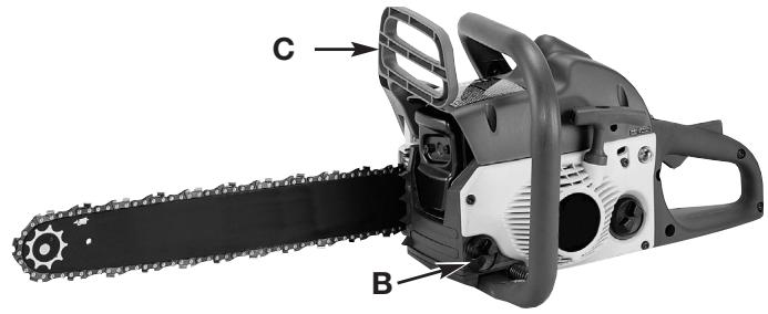
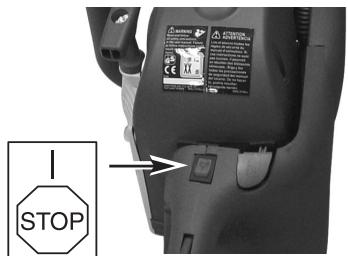
Fig. 3
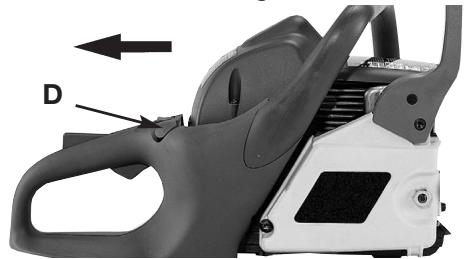
Fig. 4
Fig. 5
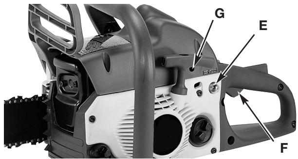
Fig. 6
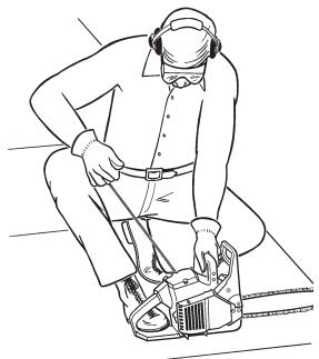
Fig. 7
OPERATING INSTRUCTIONS
FELLING
Felling is the term for cutting down a tree. Small trees up to 6-7 inches (15-18cm) in diameter are usually cut in a single cut. Larger trees require notch cuts. Notch cuts determine the direction the tree will fall.

WARNING: A retreat path (A) should be planned and cleared as necessary before cuts are started. The retreat path should extend back and diagonally to the rear of the expected line of fall, as illustrated in Fig. 8.

CAUTION: If felling a tree on sloping ground, the chain saw operator should keep on the uphill side of the terrain, as the tree is likely to roll or slide downhill after it is felled.
NOTE: Direction of fall (B) is controlled by the notching cut. Before any cuts are made, consider the location of larger branches and natural lean of the tree to determine the way the tree will fall.
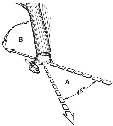
Fig. 8

WARNING: Do not cut down a tree during high or changing winds or if there is a danger to property. Consult a tree professional. Do not cut down a tree if there is a danger of striking utility wires; notify the utility company before making any cuts.
Normally felling consists of 2 main cutting operations, notching (C) and making the felling cut (D).
Start making the upper notch cut (C) on the side of the tree facing the felling direction (E). Be sure you don't make the lower cut too deep into the trunk.
The notch (C) should be deep enough to create a hinge (F) of sufficient width and strength. The notch should be wide enough to direct the fall of the tree for as long as possible.

WARNING: Never walk in front of a tree that has been notched.
Make the felling cut (D) from the other side of the tree and 1.5 - 2.0 inches (3-5 cm) above the edge of the notch (C) (Fig. 9).
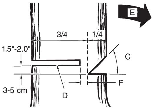
Fig. 9
Never saw completely through the trunk. Always leave a hinge. The hinge guides the tree. If the trunk is completely cut through, control over the felling direction is lost.

WARNING: Before making the final cut, always recheck the area for bystanders, animals or obstacles.
Insert a wedge or felling lever in the cut well before the tree becomes unstable and starts to move. This will prevent the guidebar from binding in the felling cut if you have misjudged the falling direction. Make sure no bystanders have entered the range of the falling tree before you push it over.
Felling Cut:
- Use wooden or plastic wedges (G) to prevent binding the bar or chain (H) in the cut. Wedges also control felling (Fig. 10).
- When diameter of wood being cut is greater than the bar length, make 2 cuts as shown (Fig. 11).

WARNING: As the felling cut gets close to the hinge, the tree should begin to fall. When tree begins to fall, remove saw from cut, stop engine, put chain saw down, and leave area along retreat path (Fig. 8).
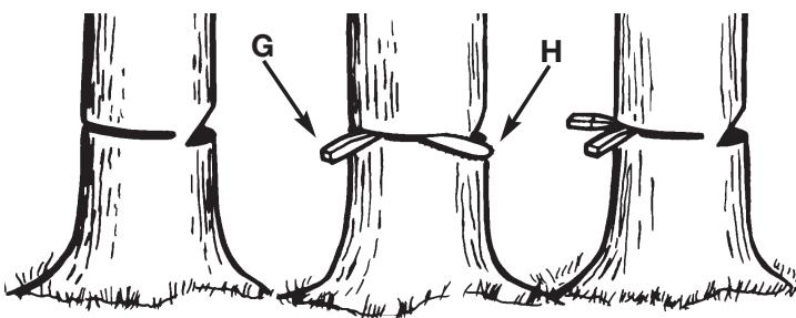
Fig. 10
OPERATING INSTRUCTIONS
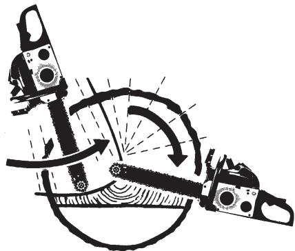
Fig. 11
LIMBING
Limbing a tree is the process of removing the branches from a fallen tree. Do not remove supporting limbs (A) until after the log is bucked (cut) into lengths (Fig. 12). Branches under tension should be cut from the bottom up to avoid binding the chain saw.
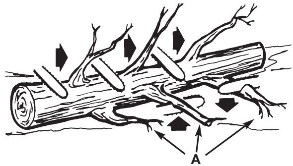
Fig. 12

WARNING: Never cut tree limbs while standing on a
tree trunk.
BUCKING
Bucking is cutting a fallen log into lengths. Make sure you have a good footing and stand uphill of the log when cutting on sloping ground. If possible, the log should be supported so that the end to be cut off is not resting on the ground. If the log is supported at both ends and you must cut in the middle, make a downward cut halfway through the log and then make the undercut. This will prevent the log from pinching the bar and chain. Be careful that the chain does not cut into the ground when bucking as this causes rapid dulling of the chain.
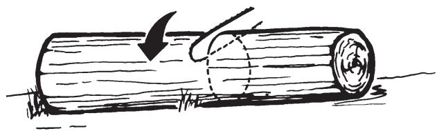
Fig. 13
When bucking on a slope, always stand on the uphill side.
- Log supported along entire length: Cut from top (overbuck), being careful to avoid cutting into the ground (Fig. 13).
- Log supported on 1 end: First, cut from bottom (underbuck) 1 / 3 diameter of log to avoid splintering. Second, cut from above (overbuck) to meet first cut and avoid pinching (Fig. 14).
- Log supported on both ends: First, overbuck 1/3 diameter of log to avoid splintering. Second, underbuck to meet first cut and avoid pinching (Fig. 15).
NOTE: The best way to hold a log while bucking is to use a sawhorse. When this is not possible, the log should be raised and supported by the limb stumps or by using supporting logs. Be sure the log being cut is securely supported.
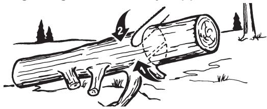
Fig. 14
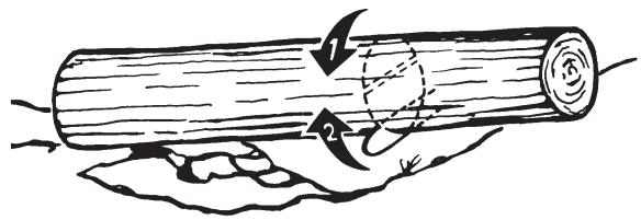
Fig. 15
BUCKING USING A SAWHORSE
For personal safety and ease of cutting, the correct position for vertical bucking is essential (Fig. 16).
A. Hold the saw firmly with both hands and keep the saw to the right of your body while cutting.
B. Keep the left arm as straight as possible.
C. Keep weight on both feet.

CAUTION: While the saw is cutting, be sure the chain and bar are being properly lubricated.
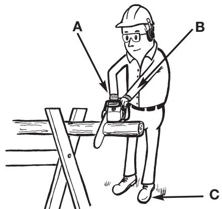
Fig. 16
MAINTENANCE AND REPAIR INSTRUCTIONS
MAINTENANCE SCHEDULE
Perform these required maintenance procedures at the frequency stated in the table. These procedures should also be a part of any seasonal tune-up.
NOTE: Some maintenance procedures may require special tools or skills. If you are unsure about these procedures take your unit to any non-road engine repair establishment, individual or authorized service dealer.
NOTE: Maintenance, replacement, or repair of the emission control devices and system may be performed by any non-road engine repair establishment, individual or authorized service dealer.

WARNING: To prevent serious injury, never perform maintenance or repairs with unit running. Always service and repair a cool unit. Disconnect the spark plug wire to ensure that the unit cannot start.
A good preventive maintenance program of regular inspection and care will increase life and improve performance of your chain saw. This maintenance checklist is a guide for such a program.
Cleaning, adjustment, and part replacement may be required, under certain conditions, at more frequent intervals than those indicated.
| MAINTENANCE CHECKLIST LISTES DES VERIFICATIONS D'ENTRETIEN LISTA DE VERIFUCION DEL MANTENIMIENTO | EACH USE CHAQUE USAGE CADA USO | HOURS OF OPERATION HEURES D'OPERATION HORAS DE OPERACION | ||
| ITEM / PIECE / PARTE | ACTION / ACTION / ACCION | 10 | 20 | |
| SCREWS / NUTS / BOLTS VIS / ECROUS / BOULONS TORNILLOS / TUERCAS / PERNOS | INSPECT / TIGHTEN INSPECTER / RESSERRER INSPECCIONAR / APRETAR | ✓ | ||
| AIR FILTER FILTRÉ A AIR FILTRÖ DE AIRE | CLEAN OR REPLACE NETTOYER OU REMPLACER LIMPIAR O REEMPLAZAR | ✓ | ||
| FUEL FILTER / OIL FILTER FILTRE ESSENCE / FILTRE A HUILE FILTRO DEL COMBUSTIBLE / FILTRO DE ACEITE | REPLACE REPLACER REEMPLAZAR | ✓ | ||
| SPARK PLUG BOUGIE BUJIA DE ENCENDIDO | CLEAN / ADJUST / REPLACE NETTOYER / REGLER / REMPLACER LIMPIAR / AJUSTAR / REEMPLAZAR | ✓ | ||
| SPARK ARRESTER SCREEN ECRAN PARE-ETINCELLES PANTALLA DEL PARACHISPAS | INSPECT INSPECTER INSPECCIONAR | ✓ | ||
| REPLACE AS REQUIRED REPLACER SUIVANT LES BESOINS REEMPLAZAR SEGUN SE REQUIERA | ✓ | |||
| FUEL HOSES DURITS D'ESSENCE MANGUERAS DE COMBUSTIBLE | INSPECT INSPECTER INSPECCIONAR | ✓ | ||
| *REPLACE AS REQUIRED *REPLACER SUIVANT LES BESOINS *REEMPLAZAR SEGUN SE REQUIERA | ||||
| CHAIN BRAKE® COMPONENTS COMPOSANTS DE CHAIN BRAKE® COMPONENTES DEL CHAIN BRAKE® | INSPECT INSPECTER INSPECCIONAR | ✓ | ||
| *REPLACE AS REQUIRED *REPLACER SUIVANT LES BESOINS *REEMPLAZAR SEGUN SE REQUIERA | ||||
Recommended for Maintenance by an Authorized Service Center Technician.
It est recommendé de confier ces opérations à un technicien agréé.
*Recommendamos que le Centro de Servicio Autorizzato proporcione el mantenimiento.
MAINTENANCE AND REPAIR INSTRUCTIONS
INSTALL THE GUIDE BAR

CAUTION: To ensure the bar and chain receive oil, ONLY USE THE ORIGINAL STYLE BAR with the oil passage hole (A) as illustrated in Fig. 17.
- Make sure the Chain Brake lever is pulled back into the DISENGAGED position (Fig. 17).
- Remove the bar retaining nut (B1) and the screw (B2) at rear of clutch cover (C). Remove clutch cover (C) by pulling straight out, some force may be required. (Fig. 18).
- Place the slotted end of the guide bar over the bar bolt (F). Slide guide bar behind clutch drum (G) until the guide bar stops (Fig. 19).

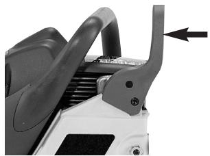
Fig. 17
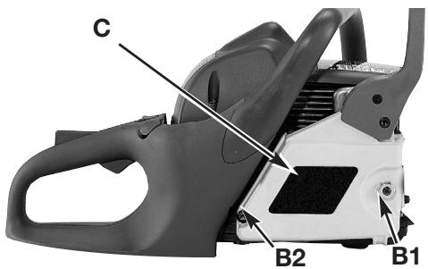
Fig. 18
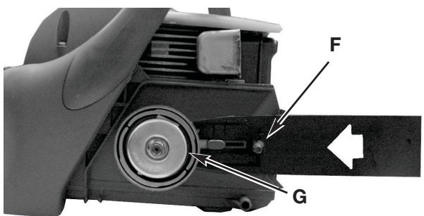
Fig. 19
INSTALL THE SAW CHAIN

WARNING: Always use protective gloves when handling the saw chain.
- Spread chain out in a loop with cutting edges (A) pointing CLOCKWISE around loop (Fig. 20).
- Slip the chain around the sprocket (B) behind the clutch (C). Make sure the links fit between the sprocket teeth (Fig. 21).
- Guide the drive links into the groove (D) and around the end of the bar (Fig. 21).
NOTE: The saw chain may droop slightly on the lower part of bar. This is normal.
- Pull guide bar forward until chain is snug. Ensure all drive links are in the bar groove.
- Install the clutch cover. Make sure the chain does not slip off of the bar. Install the bar retaining nut hand tight and follow tension adjustment instructions in the next section. Replace screw at rear of clutch cover.
NOTE: The guide bar retaining nut is installed only hand tight at this point because saw chain adjustment is required. Follow instructions in Saw Chain Tension Adjustment.
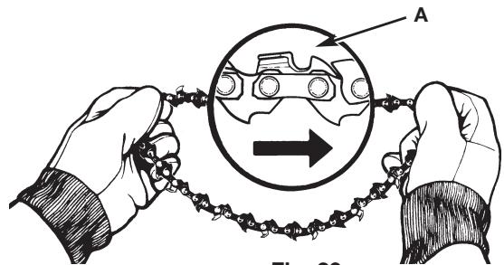
Fig. 20
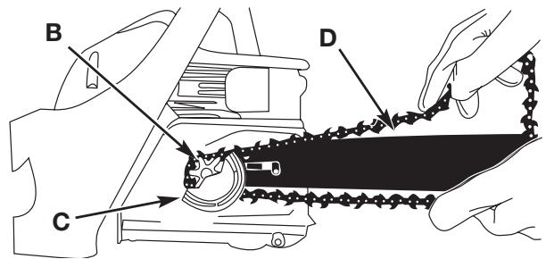
Fig. 21
MAINTENANCE AND REPAIR INSTRUCTIONS
SAW CHAIN TENSION ADJUSTMENT

WARNING: Always use protective gloves when handling the saw chain.
Proper tension of saw chain is extremely important and must be checked before starting, as well as during any cutting operation.
Taking the time to make needed adjustments to the saw chain will result in improved cutting performance and prolonged chain life.
To adjust the saw chain:
- Loosen bar nut, then hold nose of guide bar up and turn adjustment screw (D) CLOCKWISE to increase chain tension. Turning screw COUNTERCLOCKWISE will decrease amount of tension on chain. Ensure the chain fits snugly all the way around the guide bar (Fig. 22).
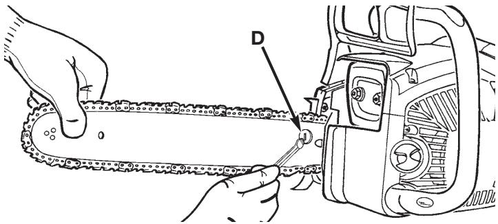
Fig. 22
- After making adjustment, and while still holding nose of bar in the uppermost position, tighten the bar retaining nut securely. Chain has proper tension when it has a snug fit all around and can be pulled around by gloved hand.
NOTE: If chain is difficult to rotate on guide bar or if it binds, too much tension has been applied. This requires minor adjustment as follows:
A. Loosen the bar retaining nut so it is finger tight. Decrease tension by turning the bar adjustment screw COUNTERCLOCKWISE slowly. Move chain back and forth on bar. Continue to adjust until chain rotates freely, but fits snugly. Increase tension by turning bar adjustment screw CLOCKWISE.
B. When saw chain has proper tension, hold nose of bar in uppermost position and tighten the bar retaining nut securely.
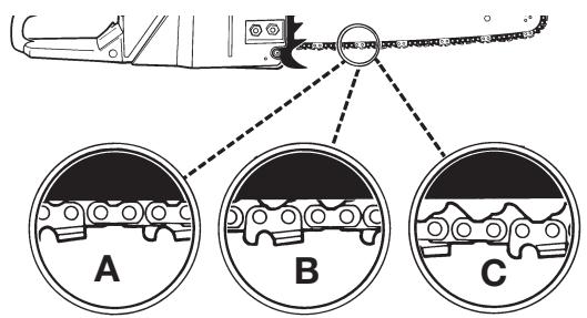
Fig. 23

CAUTION: A new saw chain stretches, requiring adjustment after as few as 5 cuts. This is normal with a new chain, and the interval between future adjustments will lengthen quickly.

CAUTION: If saw chain is TOO LOOSE or TOO
TIGHT, the sprocket, bar, chain, and crankshaft bearings will wear more rapidly. Study Fig. 23 for information concerning correct cold tension (A), correct warm tension (B), and as a guide for when saw chain needs adjustment (C).
CHAIN BRAKE MECHANICAL TEST

WARNING: The purpose of the Chain Brake® is to reduce the possibility of injury due to kickback; however, it cannot provide the intended measure of protection if the saw is operated carelessly.
Always test the Chain Brake® before using your saw and periodically while on the job.
Your chain saw is equipped with a Chain Brake® that reduces possibility of injury due to kickback. The brake is activated if pressure is applied against brake lever when, as in the event of kickback, operator's hand strikes the lever. When the brake is actuated, chain movement stops abruptly.
To Test the Chain Brake®:
- The Chain Brake® is DISENGAGED (chain can move) when BRAKE LEVER IS PULLED BACK AND LOCKED (A, Fig. 24).
- The Chain Brake® is ENGAGED (chain is stopped) when brake lever is in forward position. You should not be able to move chain (B, Fig. 24).
NOTE: The brake lever should snap into both positions. If strong resistance is felt, or lever does not move into either position, do not use your saw. Take it immediately to a Authorized Service Center for repair. Call 1-800-520-5520 for more information.
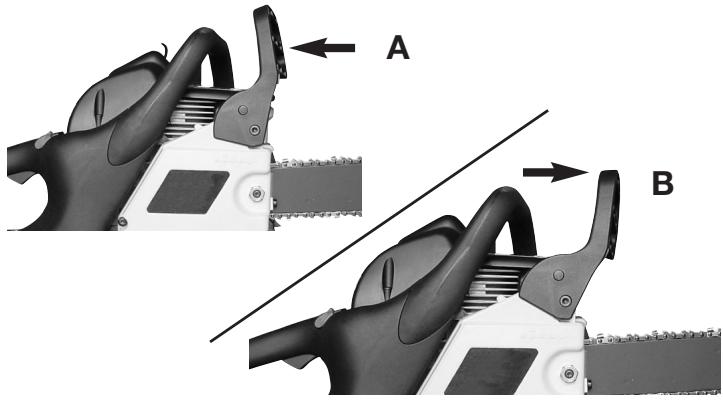
Fig. 24
MAINTENANCE AND REPAIR INSTRUCTIONS
AIR FILTER

CAUTION: Never operate saw without the air filter. Dust and dirt will be drawn into engine and damage it. Keep the air filter clean.
- Remove the top cover (A) by loosening the cover retaining screws. Cover will lift off (Fig. 25).
- Lift the air filter (B) out of air-box (C) (Fig. 26).
- Clean air filter. Wash filter in clean, warm, soapy water. Rinse in clear, cool water. Air dry completely.
NOTE: It is advisable to have a supply of spare filters.
4. Install air filter. Install engine / air filter cover. Make sure cover fits properly. Tighten the cover retaining screws securely.

WARNING: To avoid serious personal injury, always turn your unit off and allow it to cool before you clean or service it.
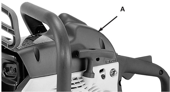
Fig. 25
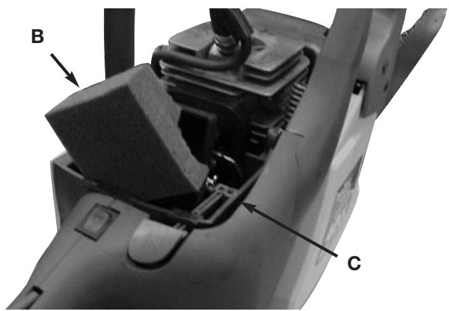
Fig. 26
FUEL FILTER

CAUTION: Never operate saw without the fuel filter. The fuel filter should be replaced after each 20 hours of use. Drain fuel tank before changing.
- Remove the fuel tank cap.
- Bend a piece of soft wire.
- Reach into fuel tank opening and hook fuel line. Carefully pull the fuel line toward the opening until you can reach it with your fingers.
NOTE: Do not pull hose completely out of tank.
- Lift filter (A) out of tank (Fig. 27).
- Pull filter off with a twisting motion. Discard filter.
- Install new filter. Insert end of filter into tank opening. Make sure filter sits in bottom corner of tank. Use a long handle screwdriver to aid in filter placement if necessary.
- Fill tank with fresh fuel / oil mixture. See Oil and Fuel Information page 9. Install fuel cap.
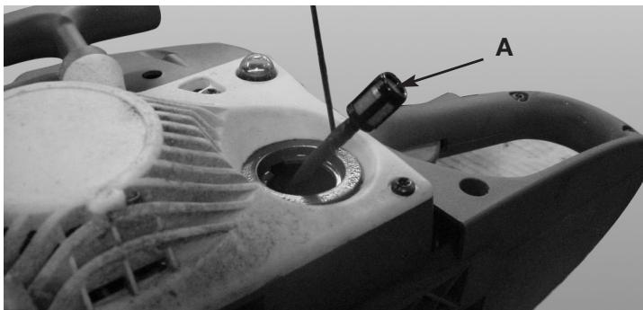
Fig. 27
MAINTENANCE AND REPAIR INSTRUCTIONS
SPARK ARRESTER SCREEN
NOTE: A clogged spark arrester screen will dramatically reduce engine performance.
- Remove the 3 bolts (A) and pull muffler out. (Fig. 28).
- Remove the 2 screws (B) that hold the spark arrester cover (C) (Fig. 29).
- Discard the used spark arrester screen (D) and replace it with a new one.
- Reassemble the muffler components and install the muffler to the cylinder. Tighten securely.
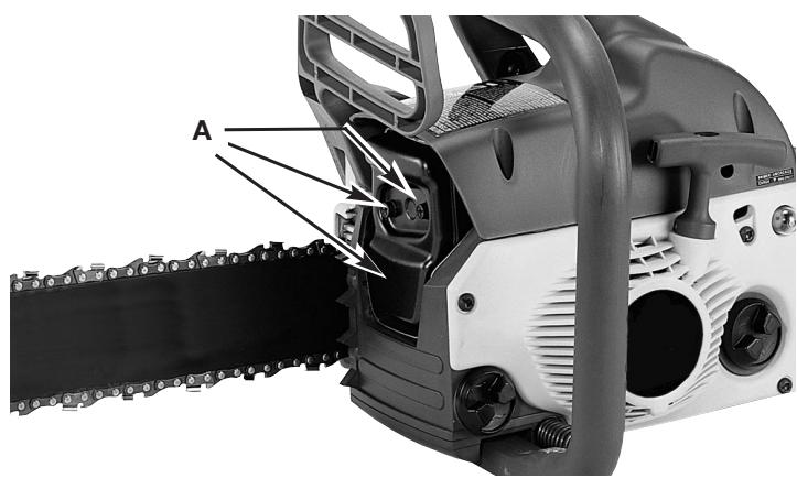
Fig. 28
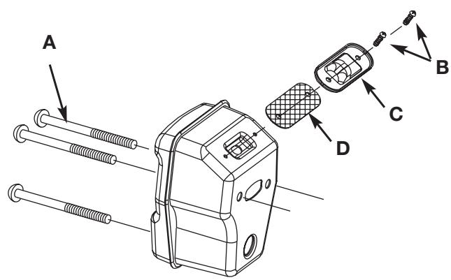
Fig. 29
SPARK PLUG
NOTE: For efficient operation of saw engine, spark plug must be kept clean and properly gapped.
- Push STOP switch down.
- Remove air cleaner cover.
- Disconnect the wire connector (G) from the spark plug (H) by pulling and twisting at the same time (Fig. 30).
- Remove spark plug with spark plug socket wrench. DO NOT USE ANY OTHER TOOL.

WARNING: Do not sand blast, scrape or clean electrodes. Grit in the engine could damage the cylinder.
- Check electrode gaps with wire feeler gauge and set gaps to .025" (.635mm) if necessary.
- Reinstall a new spark plug.
NOTE: A resistor spark plug must be used for replacement (part no. 9295-310502).
NOTE: This spark ignition system meets all requirements of the Canadian Interferen-Causing Equipment Regulations.
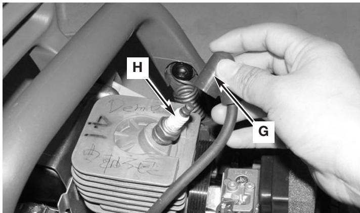
Fig. 30
CARBURETOR ADJUSTMENT
The carburetor was pre-set at the factory for optimum performance. If further adjustments are necessary, please take your unit to the nearest Authorized Service Center listed in the Yellow Pages. Call 1-800-520-5520 for more information.
STORING A CHAIN SAW

CAUTION: Never store a chain saw for longer than 30 days without performing the following procedures.
Storing a chain saw for longer than 30 days requires storage maintenance. Unless the storage instructions are followed, fuel remaining in the carburetor will evaporate, leaving gum-like deposits. This could lead to difficult starting and result in costly repairs.
- Remove the fuel tank cap slowly to release any pressure in tank. Carefully drain the fuel tank.
- Start the engine and let it run until the unit stops to remove fuel from carburetor.
- Allow the engine to cool (approx. 5 minutes).
- Using a spark plug wrench, remove the spark plug.
- Pour 1 teaspoon of clean 2-cycle oil into the combustion chamber. Pull starter rope slowly several times to coat internal components. Replace spark plug (Fig. 31).
NOTE: Store the unit in a dry place and away from possible sources of ignition such as a furnace, gas hot water heater, gas dryer, etc.
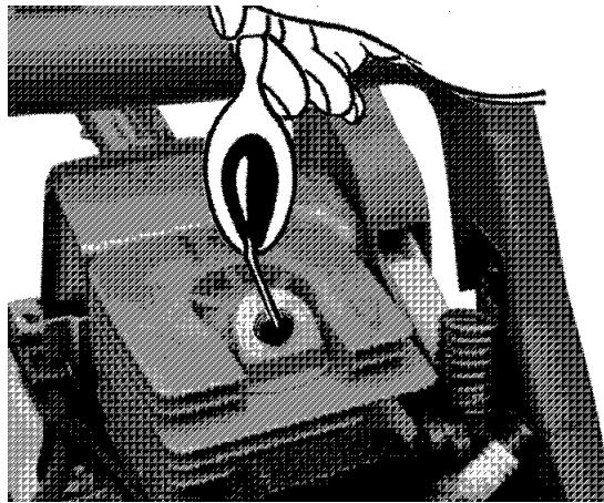
Fig. 31
REMOVING A UNIT FROM STORAGE
- Remove spark plug.
- Pull starter rope briskly to clear excess oil from combustion chamber.
- Clean and gap spark plug or install a new spark plug with proper gap.
- Prepare unit for operation.
- Fill fuel tank with proper fuel / oil mixture. See Oil and Fuel Information.
GUIDE BAR MAINTENANCE
Frequent lubrication of the guide bar (railed bar which supports and carries the saw chain) sprocket tip is required. Proper maintenance of the guide bar, as explained in this section, is essential to keep your saw in good working condition.
Sprocket Tip Lubrication

CAUTION: The sprocket tip on your new saw has been pre-lubricated at the factory. Failure to lubricate the guide bar sprocket tip as explained below will result in poor performance and seizure, voiding the manufacturer's warranty.
Lubrication of the sprocket tip is recommended after 10 hours of use or once a week, which ever occurs first. Always thoroughly clean guide bar sprocket tip before lubrication.
The Lube Gun (optional) is recommended for applying grease to the guide bar sprocket tip. The Lube Gun is equipped with a needle nose tip which is necessary for the efficient application of grease to the sprocket tip.
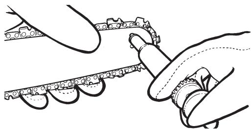
Fig. 32
To lubricate the sprocket tip:
- Move the STOP switch down.
NOTE: It is not necessary to remove the saw chain to lubricate the guide bar sprocket tip. Lubrication can be done on the job.
- Clean the guide bar sprocket tip.
- Using the Lube Gun (optional), insert tip of lube gun into the lubrication hole and inject grease until it appears at outside edge of sprocket tip (Fig. 32).
- Rotate saw chain by hand. Repeat lubrication procedure until the entire sprocket tip has been greased.
SAW CHAIN / BAR LUBRICATION
Adequate lubrication of the saw chain is essential at all times to minimize friction with the guide bar.
Never starve the bar and chain of oil. Running the saw with too little oil will decrease cutting efficiency, shorten saw chain life, cause rapid dulling of chain, and cause excessive wear of bar from overheating. Too little oil is evidenced by smoke, bar discoloration or pitch build-up.
NOTE: Saw chain stretches during use, particularly when it is new, and it will occasionally be necessary to adjust and tighten it. New chain will require adjustment after about 5 minutes of operation.
AUTOMATIC OILER
Your chain saw is equipped with an automatic gear driven oiler system. The oiler automatically delivers the proper amount of oil to the bar and chain. As the engine speed increases, so does the oil flow to the bar pad. There is no flow adjustment. The oil reservoir will run out at approximately the same time as the fuel supply runs out.
MAINTENANCE AND REPAIR INSTRUCTIONS
GUIDE BAR MAINTENANCE:
Most guide bar problems can be prevented merely by keeping the chain saw well maintained.
Insufficient guide bar lubrication and operating the saw with chain that is too tight will contribute to rapid bar wear.
To help minimize bar wear, the following guide bar maintenance procedures are recommended.
BAR WEAR - Turn guide bar frequently at regular intervals (for example, after 5 hours of use), to ensure even wear on top and bottom of bar.
BAR GROOVES - Bar grooves (or rails which support and carry the chain) should be cleaned if saw has been used heavily or if saw chain appears dirty. Rails should always be cleaned every time saw chain is removed.
OIL PASSAGES - Oil passages on the bar should be cleaned to ensure proper lubrication of the bar and chain during operation.
NOTE: The condition of the oil passages can be easily checked. If the passages are clear, the chain will automatically give off a spray of oil within seconds of starting the saw. Your saw is equipped with an automatic oiler system.
CHAIN MAINTENANCE
Chain Tension
Check the chain tension frequently and adjust as often as necessary to keep the chain snug on the bar, but loose enough to be pulled around by hand.
Breaking in a New Saw Chain
A new chain and bar will need chain readjustment after as few as 5 cuts. This is normal during the break-in period, and the interval between future adjustments will begin to lengthen quickly.

WARNING: Never have more than 3 links
removed from a loop of chain. This could cause damage to the sprocket.
Chain Lubrication
Always make sure the automatic oiler system is working properly. Keep the oil tank filled with Genuine Factory Parts Chain, Bar and Sprocket Oil.
Adequate lubrication of the bar and chain during cutting operations is essential to minimize friction with the guide bar.
Never starve the bar and chain of lubricating oil. Running the saw dry or with too little oil will decrease cutting efficiency, shorten saw chain life, cause rapid dulling of chain, and lead to excessive wear of bar from overheating. Too little oil is evidenced by smoke or bar discoloration.
Chain Sharpening
Chain sharpening requires special tools to ensure that cutters are sharpened at the correct angle and depth. For the inexperienced chain saw user, we recommend that the saw chain be professionally sharpened by the nearest Authorized Service Center. If you feel comfortable sharpening your own saw chain, special tools are available from your Authorized Service Center.
CHAIN REPLACEMENT INFORMATION
There may be other quality equivalent replacement components for achieving kickback protection.
| Bar Length | Drive Links | Part Number |
| 16” Bar | 54 DL | 6220-210816 |
| 18” Bar | 60 DL | 6220-210805 |
INERTIA CHAIN BRAKE® ACTION
NOTE: THIS SAW IS EQUIPPED WITH AN INERTIA CHAIN BRAKE. IF THE SAW KICKS BACK WHILE IN USE, THE INERTIA OF THE MOVING SAW WILL ACTIVATE THE BRAKE. A BRAKE BAND AROUND THE CLUTCH DRUM ACTIVATES AND STOPS THE MOVING CHAIN.
Test the Chain Brake® periodically to ensure proper function.
Perform a Chain Brake® test prior to initial cutting, following extensive cutting, and definitely following any Chain Brake® service. Test the Chain Brake:
- Place saw on a clear, firm, flat surface.
- Start engine.
- Grasp the rear handle (A) with your right hand (Fig. 33).
- With your left hand, hold the front handle (B) [not Chain Brake lever (C)] firmly (Fig. 33).
- Squeeze the throttle trigger to 1/3 throttle, then immediately activate the Chain Brake lever (C) (Fig. 33).

WARNING: Activate the Chain Brake® slowly and
deliberately. Keep the chain from touching anything; don't let the saw tip forward.
- Chain should stop abruptly. When it does, immediately release the throttle trigger.

WARNING: If chain does not stop, turn engine off
and take your unit to the nearest Authorized Service Center for service.
- If Chain Brake® functions properly, turn the engine off and return the Chain Brake® to the DISENGAGED position.
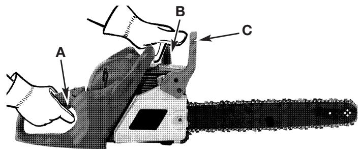
Fig. 33
TROUBLESHOOTING
UNIT WON'T START OR STARTS BUT WILL NOT RUN
CAUSE
Incorrect starting procedures
Incorrect carburetor mixture adjustment setting
Fouled spark plug
ACTION
Follow instructions in the Starting/Stopping section
Have carburetor adjusted by Authorized Service Center
Clean / gap or replace plug
UNIT STARTS, BUT ENGINE HAS LOW POWER
CAUSE
Fuel filter is plugged
Incorrect lever position
Dirty spark arrester screen
Dirty air filter
Incorrect carburetor mixture adjustment setting
ACTION
Replace the fuel filter
Move to RUN position
Replace spark arrester screen.
Remove, clean and reinstall filter.
Have carburetor adjusted by Authorized Service Center
ENGINE HESITATES
CAUSE
Incorrect carburetor mixture adjustment setting
ACTION
Have carburetor adjusted by Authorized Service Center
NO POWER UNDER LOAD
CAUSE
Incorrect carburetor mixture adjustment setting
ACTION
Have carburetor adjusted by Authorized Service Center
RUNS ERATICALLY
CAUSE
Incorrectly gapped spark plug
ACTION
Clean / gap or replace plug
SMOKES EXCESSIVELY
CAUSE
Incorrect carburetor mixture adjustment setting
Incorrect fuel mixture
ACTION
Have carburetor adjusted by Authorized Service Center
Use properly mixed fuel (40:1 mixture)
If further assistance is required, contact your authorized service dealer.
Call 1-800-520-5520 for more information.
NOTES
MANUFACTURER'S LIMITED WARRANTY FOR:
TROY-BILT®
The limited warranty set forth below is given by Troy-Bilt LLC with respect to new merchandise purchased and used in the United States, its possessions and territories.
Troy-Bilt LLC warrants this product against defects in material and workmanship for a period of one (1) year commencing on the date of original purchase and will, at its option, repair or replace, free of charge, any part found to be defective in material or workmanship. This limited warranty shall only apply if this product has been operated and maintained in accordance with the Operator's Manual furnished with the product, and has not been subject to misuse, abuse, commercial use, neglect, accident, improper maintenance, alteration, vandalism, theft, fire, water or damage because of other peril or natural disaster. Damage resulting from the installation or use of any accessory or attachment not approved by Troy-Bilt LLC for use with the product(s) covered by this manual will void your warranty as to any resulting damage. This warranty is limited to ninety (90) days from the date of original retail purchase for any Troy-Bilt product that is used for rental or commercial purposes, or any other income-producing purpose.
HOW TO OBTAIN SERVICE: Warranty service is available, WITH PROOF OF PURCHASE THROUGH YOUR LOCAL AUTHORIZED SERVICE DEALER. To locate the dealer in your area, visit our website at www.troybilt.com, check for a listing in the Yellow Pages, call 1-800-520-5520 or write to P.O. Box 361131, Cleveland, OH 44136-0019.
This limited warranty does not provide coverage in the following cases:
A. Tune-ups - Spark Plugs, Carburetor Adjustments, Filters
B. Wear items - Bump Knobs, Outer Spools, Cutting Line, Inner Reels, Starter Pulley, Starter Ropes, Drive Belts
C. Troy-Bilt LLC does not extend any warranty for products sold or exported outside of the United States of America, its possessions and territories, except those sold through Troy-Bilt's authorized channels of export distribution.
Troy-Bilt LLC reserves the right to change or improve the design of any Troy-Bilt Product without assuming any obligation to modify any product previously manufactured.
No implied warranty, including any implied warranty of merchantability or fitness for a particular purpose, applies after the applicable period of express written warranty above as to the parts as identified. No other express warranty or guaranty, whether written or oral, except as mentioned above, given by any person or entity, including a dealer or retailer, with respect to any product shall bind Troy-Bilt LLC During the period of the Warranty, the exclusive remedy is repair or replacement of the product as set forth above. (Some states do not allow limitations on how long an implied warranty lasts, so the above limitation may not apply to you.)
The provisions as set forth in this Warranty provide the sole and exclusive remedy arising from the sales. TroyBilt LLC shall not be liable for incidental or consequential loss or damages including, without limitation, expenses incurred for substitute or replacement lawn care services, for transportation or for related expenses, or for rental expenses to temporarily replace a warranted product. (Some states do not allow limitations on how long an implied warranty lasts, so the above limitation may not apply to you.)
In no event shall recovery of any kind be greater than the amount of the purchase price of the product sold. Alteration of the safety features of the product shall void this Warranty. You assume the risk and liability for loss, damage, or injury to you and your property and/or to others and their property arising out of the use or misuse or inability to use the product.
This limited warranty shall not extend to anyone other than the original purchaser, original lessee or the person for whom it was purchased as a gift.
How State Law Relates to this Warranty: This warranty gives you specific legal rights, and you may also have other rights which vary from state to state.
To locate your nearest service dealer dial 1-800-520-5520.
Troy-Bilt LLC
P.O. Box 361131
Cleveland, OH 44136-0019
TROY-BILT®
RÉFERENCES, ILLUSTRATIONS ET SPECIFICATIONS RELATIVES AU PRODUIT
SAVE THESE INSTRUCTIONS
CONSIGNES DE SECURITÉ
SYMBOLES DE SECURITE ET INTERNATIONALEX
∴ m = 3/11
2 : x ( x) = 0. .
∴ m = 3/11
一
1-7 9PC-10-34.5 PIN,PISTON
1-8 9CA-10.3 RING
1-9 9072-310501F
1-10 9295-310502
1-11 9292-310501F
1-12 9012-310502
1-13 9082-310505
1-14 9STDB-05-60
1-15 9082-310504
1-16 6WSB-06
1-17 9SACB-06-25
1-18 9082-310506
1-19 9287-310501
1-20 9228-310510
1-21 9NHZ-05
1-22 9SGKBY10/14-0.625
1-23 9068-310501
1-24 9028-310502
1-25 9028-310501
1-26 9024-310504
1-27 9SKKBY10/14-0.68
1-28 9027-310101
1-29 9068-310502
Description
ENG ASS'Y
CAP, BEARING
BEARING
CRANK/ROD ASS'Y
PISTON
RING, PISTON
ROLLER, PISTON
PIN, PISTON
RING
CASE, CRANK
SPARK PLUG
CYLINDER
RUBBER, ISOLATOR
SPACER
SCREW
ISOLATOR, CARBURETOR
SPRING WASHER
SCREW
SPACER
CARBURETOR
AIR FILTER ASS/Y
NUT
SCREW
HANDLE,LEFT PART
TRIGGER, THROTTLE
TRIGGER, RELEASE
SPRING
SCREW
RUBBER
HANDLE, REAR
Item Parts No.
1-30 9022-310501
1-31 9WFB-05-21
1-32 9SKKBY8/16-0.625
1-33 9068-MD0701
1-34 9228-MD0701
1-35 9NAB-5/16-24
1-36 9169-310501
1-37 9SKKBY8/16-0.75
1-38 9010-310503
1-39 9288-310501-CH
1-40 9051-310501
1-41 9228-310207
1-42 9228-310514
1-43 9142-310002
1-44 9157-310501
1-45 9024-310506
1-46 9SFABJ06-55
1-47 6SDABB04-08
1-48 9228-310511
1-49 9012-310503
1-50 9114-310510
1-51 9012-310504
1-52 9024-310507
1-53 9124-310102
1-54 9013-310501
1-55 9228-310526
1-56 9073-310503
1-57 9082-310507
1-589082-310502
1-59 9082-310501
Description
SWITCH
WASHER
SCREW
HANDLE,FRONT
STARTER HOUSING ASS'Y
NUT
FLYWHEEL
SCREW
WIRE ASS'Y
IGNITION ASS'Y
CONDUCTIVE PLATE
OIL CAP ASSY
SPRING ASS'Y
PRIMER
FELT
SPRING
SCREW
SCREW
HOUSINGASS'Y
HOLDER, CABLE
LEVER, CHOKE
HOLDER, CHOKE LEVEL
SPRING
CONNECTOR
OIL PIPE
PUMP ASS'Y
WORM
SPACER
BAEELE
BAFFLE
Item Parts No.
1-60 9228-310504
1-61 9SXDB-06-70
1-62 9010-310502
1-63 9129-310504
1-64 9221-310001
1-65 9183-310502
1-66 9252-310501
1-67 9082-310508
1-68 9SKKBY-8/16-1
1-69 9SKKBY8/16-1.4
1-70 9017-310509
1-71 9017-310508
1-72 9SKKBY8/16-
2 9228-310515
3 9228-310528
4 9077-310501
5 9NHC-09
6 9228-MD0702
7 9NAZ-5/16-18
8 9040-MD0702
9040-MD0703
9 6220-210816
6220-210805
10 9SGKBY10/14-0.625
11 9228-310206
12 9182-310001
13 9042-310201
14 9017-310214
15 9120-MD0701
Description
MUFFLER ASS'Y
SCREW
CABLE, THROTTLE
FUEL PIPE
WOODRUFF KEY
MESH
FILTER, AIR
BAFFLE
SCREW
SCREW
SHROUD
CAP, ANTI-DUST
SCREW
DRUM A
CLUTCH ASS'Y
CAP, ANTI-DUST
NUT
BRAKE KIT ASSY
NUT
BAR(TB4016CC)
BAR(TB4218CC)
CHAIN(TB4016CC)
CHAIN(TB4218CC)
SCREW
FUEL CAP ASS'Y
FILTER
WRENCH
SCABBARD
CARRY CASE
GARANTÍA LIMITADA DEL FABRICANTE PARA:
TROY-BILT®
- 2-CYCLE GAS CHAIN SAWS
- MODEL TB4016CC
- MODEL TB4218CC
- WARNING · PLEASE READ
- SAVE THESE INSTRUCTIONS
- DO NOT THROW AWAY
- INTRODUCTION
- THANK YOU
- PRODUCT REFERENCES, ILLUSTRATIONS AND SPECIFICATIONS
- SERVICE INFORMATION
- DO NOT RETURN THE UNIT TO THE RETAILER. PROOF OF PURCHASE WILL BE REQUIRED FOR WARRANTY SERVICE
- TABLE OF CONTENTS
- SPARK ARRESTOR NOTE
- CALIFORNIA PROPOSITION 65 WARNING
- SYMBOL MEANING
- IMPORTANT SAFETY INSTRUCTIONS
- READ ALL INSTRUCTIONS BEFORE OPERATING
- WHILE OPERATING
- KICKBACK SAFETY PRECAUTIONS
- OTHER SAFETY PRECAUTIONS
- FUEL SAFETY
- SAFETY AND INTERNATIONAL SYMBOLS
- ROTATIONAL KICKBACK
- KICKBACK SPECIFICS
- PINCH KICKBACK
- OIL AND FUEL INFORMATION
- OIL AND FUEL MIXING INSTRUCTIONS
- DEFINITION OF BLENDED FUELS
- USING BLENDED FUELS
- USING FUEL ADDITIVES
- STARTING/STOPPING INSTRUCTIONS
- STARTING INSTRUCTIONS
- STOPPING INSTRUCTIONS
- OPERATING INSTRUCTIONS
- FELLING
- FELLING CUT
- LIMBING
- BUCKING
- BUCKING USING A SAWHORSE
- MAINTENANCE AND REPAIR INSTRUCTIONS
- MAINTENANCE SCHEDULE
- INSTALL THE GUIDE BAR
- INSTALL THE SAW CHAIN
- SAW CHAIN TENSION ADJUSTMENT
- CHAIN BRAKE MECHANICAL TEST
- AIR FILTER
- FUEL FILTER
- SPARK ARRESTER SCREEN
- SPARK PLUG
- CARBURETOR ADJUSTMENT
- STORING A CHAIN SAW
- REMOVING A UNIT FROM STORAGE
- GUIDE BAR MAINTENANCE
- SPROCKET TIP LUBRICATION
- SAW CHAIN / BAR LUBRICATION
- AUTOMATIC OILER
- CHAIN MAINTENANCE
- CHAIN TENSION
- BREAKING IN A NEW SAW CHAIN
- WARNING: NEVER HAVE MORE THAN 3 LINKS
- CHAIN LUBRICATION
- CHAIN SHARPENING
- CHAIN REPLACEMENT INFORMATION
- INERTIA CHAIN BRAKE® ACTION
- WARNING: ACTIVATE THE CHAIN BRAKE® SLOWLY AND
- WARNING: IF CHAIN DOES NOT STOP, TURN ENGINE OFF
- TROUBLESHOOTING
- UNIT WON'T START OR STARTS BUT WILL NOT RUN
- CAUSE
- ACTION
- UNIT STARTS, BUT ENGINE HAS LOW POWER
- ENGINE HESITATES
- NO POWER UNDER LOAD
- RUNS ERATICALLY
- SMOKES EXCESSIVELY
- NOTES
- MANUFACTURER'S LIMITED WARRANTY FOR
- TROY-BILT®
- THIS LIMITED WARRANTY DOES NOT PROVIDE COVERAGE IN THE FOLLOWING CASES
- TROY-BILT LLC
- RÉFERENCES, ILLUSTRATIONS ET SPECIFICATIONS RELATIVES AU PRODUIT
- CONSIGNES DE SECURITÉ
- SYMBOLES DE SECURITE ET INTERNATIONALEX
- DESCRIPTION
- ITEM PARTS NO
- GARANTÍA LIMITADA DEL FABRICANTE PARA
Brand : MTD
Model : TB4016CC
Category : Gas chainsaw