USER MANUAL GZC 75330 XB TEKA
ES Manual de Usuario
EN User Manual
FR Manuel d'Utilisation
GR User Manual
PT Manual do Utilizador
GZC SERIES
Models
GZC 31330 XBB-XBN GZC 32300 XBB-XBN GZC 63310 XBB-XBN GZC 64300 XBB-XBN GZC 64320 XBB-XBN GZC 64321 XBB-XBN White GZC 75330 XBB-XBN GZC 95320 XBB-XBN
TYPE: PCZT
Summary

Pages 4-13: Description, installation, assembly, cleaning, maintenance and the various assembly phases. Technical data.
Page 25: Instructions for installation and advice for maintenance. Instruction manual.

GZC 32300
0
GZC 64300
GZC 64320 - GZC 64321
GZC 75330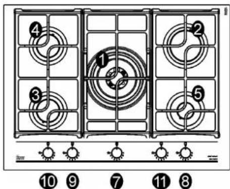


USE

(*) air inlet: see installation chapter (paragraphs 5 and 6)

FIG. 3

FIG. 4


CLEANING
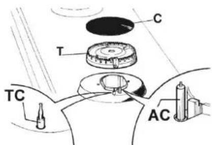
FIG. 6

FIG. 6/B


INSTALLATION

FIG. 7

Model: GZC 95320

FIG. 9

FIG. 9/A EI
INSTALLATION
INSTALLATION TYPE A: Rear black
Model: GZC 63310
GZC 64300
GZC 64320
GZC 64321
GZC 75330

Model: GZC 95320

FIG. 10
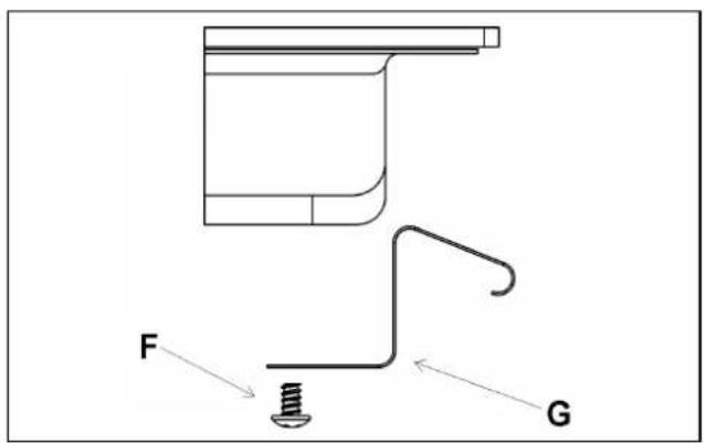

FIG. 10/BEI
INSTALLATION
Procedure for a correct installation of the hob

INSTALLATION
INSTALLATION
INSTALLATION
Mod.: GZC 31330
GZC 32300
INSTALLATION TYPE: B
INSTALLATION TYPE: B
INSTALLATION TYPE: B
FIG. - FIG. 11/B
INSTALLATION TYPE:
INSTALLATION TYPE:
INSTALLATION TYPE:
INSTALLATION TYPE:
All models
All models
All models
All models
All models
COMPLY WITH THE DIMENSIONS (in mm)
DIMENSIONS TO BE RESPECTED (in mm)
FIG. - FIG. 13

FIG. - FIG. 13/A

FIG. - FIG. 13/B

EIK. - FIG. 14
TECHNICAL DATA REGARDING THE GAS REGULATION OF THE APPLIANCE
TECHNICAL DATA FOR THE APPLIANCE GAS REGULATION
TECHNICAL DATA FOR THE APPLIANCE'S GAS REGULATION
In case of adaptation of the hob to another type of gas, operate as described in the directions for the and installation use and replace the label on the bottom with the one provided in the spare bag.
Children less than 8 years of age shall be kept away unless continuously supervised.
This appliance can be used by children aged from 8 years and above and persons with reduced physical, sensory or mental capabilities or lack of experience and knowledge if they have been given supervision or instruction concerning use of the appliance in a safe way and understand the hazards involved.
Children shall not play with the appliance.
Cleaning and user maintenance shall not be made by children without supervision.
DESCRIPTION OF HOBS
1 Ultra rapid gas burner (*DCC AFB) of 4000 W 2 Rapid gas burner of 2800 W 3 Semirapid gas burner reduced of 1400 W 4 Semirapid gas burner of 1750 W 5 Auxiliary gas burner of 1000 W 7 Burner n° 1 control kno 8 Burner n° 2 control knob 9 Burner n°3 control knob 10 Burner n° 4 control knob 11 Burner n° 5 control knob
*DCC AFB: Air From The Bottom (fig. 13/B)
Attention: this appliance has been manufactured for domestic use only and it employment by private person.

This cook top was designed to be used exclusively as a cooking appliance: any other use (such as heating rooms) is to be considered improper and dangerous.
IMPORTANT SAFETY WARNINGS

IMPORTANT WARNINGS FOR THE USER
During operation, the work surfaces of the cooking area become very hot: keep children away!
CAUTION:
In case of hotplate glass breakage:
- Shut off immediately all burners and any electrical heating element and isolate the appliance from the power supply;
- Do not touch the appliance surface;
- Do not use the appliance.
- IMPORTANT!
A perfect installation, adjustment, or transformation of the cooktop to use other gases requires a QUALIFIED INSTALLER: a failure to follow this rule will void the warranty.
- IMPORTANT: The appliance must be installed following the manufacturer's instructions. The manufacturer will not be liable for injury to persons or animals or property damage caused by an incorrect installation.
- If the installation requires modifications to the home's electrical system or if the socket is incompatible with the appliance's plug, have changes or replacements performed by a professionally qualified person. In particular, this person must also make sure that the section of the wires of the socket is suitable for the power absorbed by the appliance.
- Use of a gas cooking appliance produces heat and moisture in the room in which it is installed. The room must therefore be well ventilated by keeping the natural air vents clear (see fig. 3) and by activating the mechanical aeration device (suction hood or electric fan, fig. 4 and fig. 5).
- Intensive and lengthy use of the appliance may require additional ventilation. This can be achieved by opening a window or by increasing the power of the mechanical exhausting system if installed.
- Do not attempt to change the technical characteristics of the product because it can be dangerous.
- If you should not use this appliance any more (or replace an old model), before disposing of it, make it inoperative in conformity with current law on the protection of health and the prevention of environmental pollution by making its dangerous parts harmless, especially for children who might play on an abandoned appliance.
•CAUTION:
Do not touch the appliance with wet or damp hands or feet. Do not use the appliance barefoot.
- The manufacturer will not be liable for any damage resulting from improper, incorrect, or unreasonable use.
- During, and immediately after operation, some parts of the cooktop are very hot: avoid touching them.
- After using the cooktop, make sure that the knob is in the closed position and close the main tap of the gas supply or gas cylinder.
- If the gas taps are not operating correctly, call the Service Department.
- Keep the Warranty Certificate or the sheet of technical data with the Instructions Handbook during the appliance life. It contains important technical data.
IMPORTANT:
All our products are conform with the European Norms and relative amendments.
The product is therefore conform with the requirements of the European Directives in force relating to:
- electromagnetic compatibility (EMC);
- electrical security (LVD);
- restriction of use of certain hazardous substances (RoHS);
- EcoDesign (ERP).
The appliance complies with the provisions of the sub-regulations for European Directives:
- Regulation (EU) 2016/426.
1) BURNERS
A diagram is screen-printed above each knob on the front panel. This diagram indicates which burner the knob corresponds to. After opening the gas mains or gas bottle tap, light the burners as described below:
- Automatic electrical ignition
Push and turn the knob corresponding to the required burner anticlockwise until it reaches the full on position (position 9, fig. 1), then depress the knob. The tap is equipped with a scale of 9 positions; with each click, the flame is reduced until you reach position 1, i.e., the minimum gas supply.
- Lighting burners equipped with flame failure device
The knobs of burners equipped with flame failure device must be turned anticlockwise until they reach the full on position (position 9, fig. 1) and come to a stop. Now depress the knob in question and repeat the previously indicated operations.
Keep the knob depressed for about 10 seconds once the burner has ignited.
Then follow the instructions for using the tap as explained above.
For all models, in case of accidental extinguishment of the flame, disengage the ignition by rotating the knob to the off position. Wait at least 1 minute before re-igniting the flame.
HOW TO USE THE BURNERS
Bear in mind the following indications in order to achieve maximum efficiency with the least possible gas consumption:
- Use adequate pans for each burner (consult the following table and fig. 2).
- When the pan comes to the boil, set the knob to the reduced rate position (position 1, fig. 1).
- Always place a lid on the pans.
- Use only pan with a flat bottom.
| Burners Pan ∅ in cm |
| Ultrarapid | 24 ÷ 26 |
| Rapid | 20 ÷ 22 |
| Semirapid reduced | 16 ÷ 18 |
| Semirapid | 16 ÷ 18 |
| Auxiliary | 10 ÷ 14 |
WARNINGS:
- Burners with flame failure device may only be ignited when the relative knob has been set to the Full on position (Position 9, fig. 1).
- Matches can be used to ignite the burners in a blackout.
- Never leave the appliance unattended when the burners are being used. Make sure there are no children in the near vicinity. Particularly make sure that the pan handles are correctly positioned and keep a check on foods requiring oil and grease to cook since these products can easily catch fire.
- Never use aerosols near the appliance when it is operating.
- Containers wider than the unit are not recommended.

INSTALLATION CLEAN
IMPORTANT:
Always disconnect the appliance from the gas and electricity mains before carrying out any cleaning operation.
2) HOT PLATE
It is very important to clean the surface soon after every use, when the glass is still tepid.
Periodically wash the hot plate, the enamelled steel pan support, the enamelled burner caps "A", "B" and "C" and the burner heads "T" (see fig. 6-6/A) with lukewarm soapy water. They should also be cleaned plugs "AC" and flame detection "TC" (see fig. 6). Clean them gently with a small nylon brush as shown (see fig. 6/B) and allow to dry fully.
Do not wash in the dishwasher.
Do not allow vinegar, coffee, milk, salted water, lemon or tomato juice to remain in contact with the enamelled surfaces for long periods of time.
Do not use metallic sponges, abrasive powders, or corrosive sprays.
WARNINGS:
Comply with the following instructions before remounting the parts:
- Check that the burner head slots (see fig. 6-6/A) have not become clogged by foreign bodies.
- Check that the enamelled burner caps "A-B-C" (fig. 6-6/A) are correctly positioned on the burner head. They must be steady.
- The pan support must be placed on the appropriate centering pins, verifying perfect stability.
- Do not force the taps if they are difficult to open or close. Contact the technical assistance service for repairs.
- Do not use steam jets for cleaning the equipment.
Installation, adjustments of controls, and maintenance must only be carried out by a qualified engineer.
The appliance must be correctly installed in conformity with current law and the manufacturer's instructions.
Incorrect installation may cause damage to persons, animals, or property for which the Manufacturer shall not be considered responsible.
During the life of the system, the automatic safety or regulating devices on the appliance may only be modified by the manufacturer or by his duly authorized dealer.
3) INSTALLING THE HOT PLATE
Check that the appliance is in a good condition after having removed the outer packaging and internal wrappings from around the various loose parts. In case of doubt, do not use the appliance and contact qualified personnel.
Never leave the packaging materials (cardboard, bags, polystyrene foam, nails, etc.) within children's reach since they could become potential sources of danger.
The measurements of the opening made in the top of the modular cabinet and into which the hot plate will be installed are indicated in either fig. 7. Always comply with the measurements given for the hole into which the appliance will be recessed (see fig. 7 and 8)
The appliance belongs to class 3 and is therefore subject to all the provisions established by the provisions governing such appliances.
Note: continuous use could cause the burners to change colour due to the high temperature.
INSTALLATION
4/A) FIXING THE HOT PLATE INSTALLATION TYPE: A
The hot plate has a special seal which prevents liquid from infiltrating into the cabinet. Strictly comply with the following instructions in order to correctly apply this seal:
- Take off all the movable parts of the hob.
- Cut the seal in 4 parts of the necessary length to position it on the 4 edges of the crystal.
- Overturn the hot plate and correctly position seal "E" (fig. 11/A) under the edge of the hot plate itself, so that the outer side of the seal perfectly matches the outer perimetral edge of the crystal. The ends of the strips must fit together without overlapping.
- Evenly and securely fix the seal to the crystal, pressing it in place with the fingers.
- Place the hooks in their respective positions, use the hole no. 1 as reference for lateral position (fig. 9) and hole no. 2 for rear positions (fig. 10).
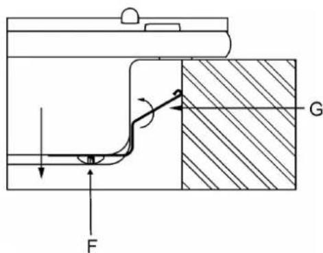
- Secure hooks "G" by means of screws "F" (fig. 9/A for lateral, and fig. 10/A for rear).
- Insert the cooking hob in the hole of the kitchen cabinet by exercising a certain level of force in order to get over the resistance of the hooks (fig. 9/B for lateral and fig. 10/B for rear). See the diagram on page 9.
- To avoid accidental contact with the overheating bottom of the hob during operation, it is necessary to install a wooden insert, fixed with screws, at a minimum distance of 70 mm from the top (see fig. 7).
4) FIXING THE HOT PLATE - INSTALLATION TYPE: B
The hot plate is equipped with a special seal that prevents liquid from seeping into the cabinet. To apply this seal correctly, strictly follow the instructions below:
- Remove all removable parts from the hob.
- Cut the seal into 4 pieces of the required length to place them on the 4 edges of the glass.
- Turn the hot plate upside down and correctly position seal "E" (fig. 11/A) under the edge of the hot plate, ensuring that the outer side of the seal aligns perfectly with the outer perimeter of the glass. The ends of the strips must fit together without overlapping.
- Press the seal evenly and firmly onto the glass with your fingers to secure it.
- Place the hob into the cutout in the cabinet and secure it using the appropriate screws "F" and fastening hooks "G" (see fig. 11).
- To avoid accidental contact with the overheating bottom of the hob during operation, it is necessary to install a wooden insert, fixed with screws, at a minimum distance of 70 mm from the top (see fig. 7).
CAUTION:
Do not place the glass directly on the cabinet.
The bottom of the hob must rest on
the cabinet.
Caution: Do not allow the glass (A) to rest directly on the worktop. The metal bottom "carter" (B) must be in contact with the worktop (see fig. 11/B).
INSTALLATION
IMPORTANT INSTALLATION INSTRUCTIONS
The installer should note that the side walls of the appliance should be no higher than the hot plate itself. Furthermore, the rear wall and the surfaces surrounding and adjacent to the appliance must be able to withstand a temperature of 90 °C.
The adhesive used to bond the plastic laminate to the cabinet must be able to withstand a temperature of at least 150 °C; otherwise, the laminate could come unstuck.
The appliance must be installed in compliance with BS 6172 1990, BS 5440 part 2 1989 and BS 6891 1988.
This appliance is not connected to a device able to dispose of the combustion fumes. It must therefore be connected in compliance with the above mentioned installation standards. Particular care should be paid to the following provisions governing ventilation and aeration.
5) ROOM VENTILATION
To ensure correct operation of the appliance, it is important to ensure that the room where the hot plate is installed has sufficient ventilation, as set out in BS 5440 part 2 1989. See table below.
Natural air flow must enter directly through permanent openings in the walls of the room in question. These
| Type of appliance | Volume of room cubic metres | Min. size of vent sq. cm. | Openable window or alternative method of venting to the outside |
| Domestic ovens | 5 | 100 | yes |
| | |
| hotplates or any combinations | 5 to 10 | 50 | yes |
| | |
| 11 to 20 | nil | yes |
| 20 and above | nil | yes |
must open towards the outside and possess a minimum section of 100 cm² (see fig. 3). It must be impossible to obstruct these openings.
Indirect ventilation with air drawn from adjacent rooms is permitted in strict compliance with the provisions in force.
6) LOCATION AND AERATION
Gas cooking appliances must always dispose of their combustion fumes through hoods. These must be connected to flues, chimneys or straight outside (see fig. 4). If it is not possible to install a hood, an electric fan can be installed on a window or on a wall facing outside (see fig. 5). This must be activated at the same time as the appliance, so long as the specifications in the provisions in force are strictly complied with.
7) GAS CONNECTION
Before connecting the appliance, check that the values on the data label affixed to the underside of the hot plate correspond to those of the gas mains in the home.
A label on the appliance indicates the regulating conditions: type of gas and working pressure.
WARNING:
a gas hot plate can only be connected by a CORGI Registered engineer.
Installations should be carried out in accordance with BS 6891 1988 and must comply with the Gas Safety Regulations.
All hot plate installations must include an isolation tap.
GAS PRESSURE TEST
Some hot plate models have a test point fitted under the control panel. To conduct a gas pressure test, proceed as follows:
- Turn off the gas supply.
- Remove the screw in the pressure test point, and place the test gauge connecting tube on the test point.
- Fit a burner ring and cap onto the burner assembly, and replace the control knob onto the corresponding control tap for the burner.
- Turn on the gas and ascertain the working pressure.
After the test, turn off the control tap, turn off the gas supply, and disconnect the test gauge connecting tube.
Replace the test point screw, turn the gas back on, and test for soundness. Reassemble the hotplate.
INSTALLATION
The electrical connections of the appliance must be carried out in compliance with the provisions and standards in force.
Before connecting the appliance, check that:
- The voltage matches the value shown on the specification plate, and the section of the wires of the electrical system can support the load, which is also indicated on the specification plate.
- The electrical capacity of the mains supply and current sockets suit the maximum power rating of the appliance (consult the data label applied to the underside of the hot plate).
- The socket or system has an efficient earth connection in compliance with the provisions and standards in force. The manufacturer declines all responsibility for failing to comply with these provisions.
When the appliance is connected to the electricity main by a socket:
- fit a standard plug "C" suited to the load indicated on the data label to the cable. Fit the wires following figure 8/A, taking care of respecting the following correspondences:
Letter L (live) = brown wire;
Letter N (neutral) = blue wire;
earth symbol ≡ green - yellow wire.
- The power supply cable must be positioned so that no part of it is able to reach a temperature of 90 °C.
- Never use reductions, adapters or shunts for connection since these could create false contacts and lead to dangerous overheating.
- The outlet must be accessible after the built-in.
When the appliance is connected straight to the electricity main:
- install an omnipolar circuit-breaker between the appliance and the electricity main. This circuit-breaker should be sized, in compliance with current installation regulations.
- Remember that the earth wire must not be interrupted by the circuit-breaker.
- For optimum safety, the electrical connection may also be protected by a high sensitivity differential circuit-breaker.
You are strongly advised to fix the relative yellow-green earth wire to an efficient earthing system.
Before performing any service on the electrical part of the appliance, it must absolutely be
disconnected from the electrical network. Always disconnect the appliance from the electricity main before making any adjustments. All seals must be replaced by the technician at the end of any adjustments or regulations. Our burners do not require primary air adjustment.
9) TAPS
"Reduced rate" adjustment
- Switch on the burner and turn the relative knob to the "Reduced rate" position (small flame fig. 1).
- Remove knob "M" (fig. 12 and 12/A) of the tap, which is simply pressed on to its rod. The by-pass for minimal rate regulation can be: beside the tap (fig. 12) or inside the shaft. In any case, to access to regulation, it can be done trough the insertion of a small screwdriver "D" beside the tap (fig. 12) or in the hole "C" inside the shaft of the tap (fig 12/A). Turn the throttle screw to the right or left until the burner flame has been adequately regulated to the "Reduced rate" position. The flame should not be too low: the lowest small flame should be continuous and steady. Re-assemble the several components.
It is understood that only burners operating with G20 gas should be subjected to the above mentioned adjustments. The screw must be fully locked when the burners operate with G30 or G31 (turn clockwise).
TAPS LUBRIFICATION
Should a tap being blocked, do not force and ask for Technical Assistance.
CONVERSIONS
10) REPLACING THE INJECTORS
The burners can be adapted to different types of gas by mounting injectors suited to the type of gas in question. To do this, first remove the burner tops using a an appropriate tool. Now unscrew injector (see fig. 13 - 13/A - 13/B) and fit a injector corresponding to the utilized type of gas in its place.
It is advisable to strongly tighten the injector in place.
To access the injector, in ultra-fast burners with DCC AFB, remove the injector cover "A" (fig. 13/B).
After the injectors have been replaced, the burners must be regulated as explained in paragraphs 9. The technician must reset any seals on the regulating or pre-regulating devices.
The envelope with the injectors and the labels can be included in the kit, or at disposal to the authorized customer Service Centre.
For the sake of convenience, the nominal rate table also lists the heat inputs of the burners, the diameter of the injectors, and the working pressures of the various types of gas.
TABLE
| BURNERS | GAS | NORMAL PRESSURE mbar | NORMAL RATE | INJECTOR DIAMETER Max100mm | NOMINAL HEAT INPUT (W) | |
| N° | DESCRIPTION | gr/h | l/h Min. | | | Gas Burner* |
| 1 | ULTRA RAPID (**DCC AFB) | G30 - BUTAN G31 - PROPAN G20 - NATURAL | 28 - 30 37 20 | 291 286 | 381 | 100 H1 100 H1 150 Z1 | 1800 1800 1800 | 4000 4000 4000 | 55,9 % |
| 2 | RAPID | G30 - BUTAN G31 - PROPAN G20 - NATURAL | 28 - 30 37 20 | 204 200 | 267 | 83 83 117 S | 900 900 900 | 2800 2800 2800 | 58,0 % |
| 3 | SEMIRAPID REDUCED | G30 - BUTAN G31 - PROPAN G20 - NATURAL | 28 - 30 37 20 | 102 100 | 133 | 60 60 88 Z | 550 550 550 | 1400 1400 1400 | 60,0 % |
| 4 | SEMIRAPID | G30 - BUTAN G31 - PROPAN G20 - NATURAL | 28 - 30 37 20 | 127 125 | 167 | 65 65 97 Z | 550 550 550 | 1750 1750 1750 | 63,0 % |
| 5 | AUXILIARY | G30 - BUTAN G31 - PROPAN G20 - NATURAL | 28 - 30 37 20 | 73 71 | 95 | 50 50 72 X | 450 450 450 | 1000 1000 1000 | N.A. |
*In accordance with Regulation No. 66/2014 EU measures for the implementation of Directive 2009/125/EC, the performance (EEgas burner) was calculated according to EN 30-2-1 last review with the G20. **DCC AFB: Air from the bottom (fig. 13/B).
SERVICING
CABLE TYPES AND SECTIONS
| TYPE OF TYPE OF SINGLE - PHASE HOT PLATE CABLE POWER SUPPLY | |
| Gas hot plate H05 RR-F Section 3 x 0.75 mm | 2 |
ATTENTION!!!
If the power supply cable is replaced, the installer should leave the ground wire (B) longer than the phase conductors (fig. 14) and comply with the recommendations given in paragraph 8.
WARNING: MAINTENANCE MUST ONLY BE PERFORMED BY AUTHORISED PERSONS.

In case of failure or cut in the cable, please move away from the cable and do not touch it. Moreover, the device must be unplugged and not switched on. Call the nearest authorized service center to fix the problem.
TECHNICAL ASSISTANCE AND SPARE PARTS
Before leaving the factory, this appliance will have been tested and regulated by expert and specialized personnel in order to guarantee the best performances.
Any repairs or adjustments which may be subsequently required may only be carried out by qualified personnel with the utmost care and attention.
For this reason, always contact your Dealer or our nearest After Sales Service Center whenever repairs or adjustments are required, specifying the type of fault and the model of the appliance in your possession.
Please also note that genuine spare parts are only available from our After Sales Service Centers and authorized retail outlets.
The above data are printed on the data label put on the inferior part of the appliance and on the packing label.
The above information gives the technical assistant the possibility to get spare parts and a timely intervention. We suggest filling in the table below.
MARK: ....
MODEL:
SERIES:
Keep the Warranty Certificate or the technical data sheet with the Instructions Handbook during the appliance's life. It contains important technical data.

This appliance is marked according to the European directive 2002/96/EC on Waste Electrical and Electronic Equipment (WEEE).
This guideline is the framework for a European-wide validity of return and recycling of Waste Electrical and Electronic Equipment.
MATERIALS:
Pag. 37 DESCRIPTION OF COOKTOP Pag. 38 IMPORTANT SAFETY WARNINGS Pag. 39 USE Pag. 40 CLEANING - INSTALLATION Pag. 41 INSTALLATION, FIXING THE COOKTOP Pag. 42 INSTALLATION Pag. 43 INSTALLATION, ELECTRICAL CONNECTION, ADJUSTING TAPS Pag. 44 CONVERSION Pag. 45 MAINTENANCE Pag. 46 AFTER-SALES SERVICE
WARNING:
INSTALLATION TYPE: A
INSTALLATION TYPE: B
TAP LUBRICATION
10) REPLACEMENT OF NOZZLES
www.teka.com
Cod: 04167E1 - 20.03.2019 - Rev. 00