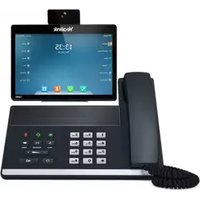
SIP VP-T49G - Telephony Yealink - Free user manual and instructions
Find the device manual for free SIP VP-T49G Yealink in PDF.


| Product Type | Smart Video Phone |
| Brand | Yealink |
| Model | SIP VP-T49G |
| Dimensions (W x H x D) | 7.48 x 9.84 x 9.06 in |
| Weight | 2.65 lbs |
| Display | 7-inch capacitive touch screen, 1024x600 resolution |
| Camera | Dual cameras (front and rear), 5 MP |
| Operating System | Android 4.4 (KitKat) |
| Power Supply | AC adapter (100-240V, 50/60Hz) or PoE (IEEE 802.3af) |
| Network Connectivity | 10/100/1000 Gigabit Ethernet |
| Wireless | Wi-Fi 802.11 b/g/n, Bluetooth 4.0 |
| Audio Features | HD voice, full-duplex speakerphone, noise cancellation |
| Video Features | HD video calling (1080p), two-way video, privacy shutter |
| Installation | Plug-and-play with SIP server, wall-mountable |
| Cleaning and Maintenance | Wipe screen with soft dry cloth; avoid liquids |
| Safety | CE, FCC, RoHS compliant; surge protection |
| Spare Parts and Repairability | Contact Yealink or authorized resellers for handset, power adapter |
| General Information | Ideal for executive offices, integrates with UC platforms |
Frequently Asked Questions - SIP VP-T49G Yealink
User questions about SIP VP-T49G Yealink
0 question about this device. Answer the ones you know or ask your own.
Ask a new question about this device
Download the instructions for your Telephony in PDF format for free! Find your manual SIP VP-T49G - Yealink and take your electronic device back in hand. On this page are published all the documents necessary for the use of your device. SIP VP-T49G by Yealink.
USER MANUAL SIP VP-T49G Yealink
Ultra-elegant Gigabit IP Phone SIP VP-T49G User Guide
Copyright
Copyright © 2017 YEALINK (XIAMEN) NETWORK TECHNOLOGY
Copyright © 2017 Yealink (Xiamen) Network Technology CO., LTD. All rights reserved. No parts of this publication may be reproduced or transmitted in any form or by any means, electronic or mechanical, photocopying, recording, or otherwise, for any purpose, without the express written permission of Yealink (Xiamen) Network Technology CO., LTD. Under the law, reproducing includes translating into another language or format.
When this publication is made available on media, Yealink (Xiamen) Network Technology CO., LTD. gives its consent to downloading and printing copies of the content provided in this file only for private use but not for redistribution. No parts of this publication may be subject to alteration, modification or commercial use. Yealink (Xiamen) Network Technology CO., LTD. will not be liable for any damages arising from use of an illegally modified or altered publication.
Trademarks
Yealink®, the logo and the name and marks is trademark of Yealink (Xiamen) Network Technology CO., LTD, which are registered legally in China, the United States, EU (European Union) and other countries.
All other trademarks belong to their respective owners. Without Yealink's express written permission, recipient shall not reproduce or transmit any portion hereof in any form or by any means, with any purpose other than personal use.
Warranty
(1) Warranty
THE SPECIFICATIONS AND INFORMATION REGARDING THE PRODUCTS IN THIS GUIDE ARE SUBJECT TO CHANGE WITHOUT NOTICE. ALL STATEMENTS, INFORMATION, AND RECOMMENDATIONS IN THIS GUIDE ARE BELIEVED TO BE ACCURATE AND PRESENTED WITHOUT WARRANTY OF ANY KIND, EXPRESS OR IMPLIED. USERS MUST TAKE FULL RESPONSIBILITY FOR THEIR APPLICATION OF PRODUCTS.
(2) Disclaimer
YEALINK (XIAMEN) NETWORK TECHNOLOGY CO., LTD. MAKES NO WARRANTY OF ANY KIND WITH REGARD TO THIS GUIDE, INCLUDING, BUT NOT LIMITED TO, THE IMPLIED WARRANTIES OF MERCHANTABILITY AND FITNESS FOR A PARTICULAR PURPOSE. Yealink (Xiamen) Network Technology CO., LTD. shall not be liable for errors contained herein nor for incidental or consequential damages in connection with the furnishing, performance, or use of this guide.
(3) Limitation of Liability
Yealink and/or its respective suppliers are not responsible for the suitability of the information contained in this document for any reason. The information is provided "as is", and Yealink does not provide any warranty and is subject to change without notice. All risks other than risks caused by use of the information are borne by the recipient. In no event, even if Yealink has been suggested the occurrence of damages that are direct, consequential, incidental, special, punitive or whatsoever (Including but not limited to loss of business profit, business interruption or loss of business information), shall not be liable for these damages.
End User License Agreement
This End User License Agreement ("EULA") is a legal agreement between you and Yealink. By installing, copying or otherwise using the Products, you: (1) agree to be bounded by the terms of this EULA, (2) you are the owner or an authorized user of the device, and (3) you represent and warrant that you have the right, authority and capacity to enter into this agreement and to abide by all its terms and conditions, just as if you had signed it. The EULA for this product is available on the Yealink Support page for the product.
Patent Information
China, the United States, EU (European Union) and other countries are protecting one or more patents of accompanying products and/or patents being applied by Yealink.
Customer Feedback
We are striving to improve our documentation quality and we appreciate your feedback. Email your opinions and comments to DocsFeedback@yealink.com.
Technical Support
Visit Yealink WIKI (http://support.yealink.com) for the latest firmware, guides, FAQ, Product documents, and more. For better service, we sincerely recommend you to use Yealink Ticketing system (https://ticket.yealink.com) to submit all your technical issues.
GNU GPL INFORMATION
Yealink SIP VP-T49G IP phone firmware contains third-party software under the GNU General Public License (GPL).
Yealink uses software under the specific terms of the GPL. Please refer to the GPL for the exact terms and conditions of the license.
The original GPL license, source code of components licensed under GPL and used in Yealink products can be downloaded online:
http://www.yealink.com/GPLOpenSource.aspx?BaseInfoCateId=293&NewsCateId=293&CateId=293
About This Guide
Thank you for choosing the SIP VP-T49G IP phone, an ultra-elegant gigabit IP phone which is exquisitely designed to provide business telephony features, such as Call Hold, Call Transfer, Busy Lamp Field, Call Recording, Multicast Paging and Conference over an IP network. It also features an enhanced user experience and newly developed industrial design, with a large touch screen for easy and efficient use.
This guide provides everything you need to quickly use your new phone. First, verify with your system administrator that the IP network is ready for phone configuration. Also be sure to read the Packaging Contents in this guide, and see the Yealink Products Regulatory Notices guide for all regulatory and safety guidance before you set up and use the SIP VP-T49G IP phone.
In This Guide
Topics provided in this guide include:
• Chapter 1 Overview
• Chapter 2 Getting Started
• Chapter 3 Customizing Your Phone
• Chapter 4 Basic Phone Features
• Chapter 5 Advanced Phone Features
Typographic Conventions
This guide contains a few typographic conventions.
You need to know the following basic typographic conventions to distinguish types of in-text information:
| Convention | Description |
| Bold | Highlights the web/phone user interface items such as menus, menu selections, soft keys, or directory names when they are involved in a procedure or user action (e.g., Tap Menu->Status). Also used to emphasize text (e.g., Important!). |
| Blue Text | Used for cross references to other sections within this documentation (e.g., refer to Overview). |
| Blue Text in Italics | Used for hyperlinks to Yealink resources outside of this documentation such as the Yealink documentations (e.g., For more information, refer to Yealink Meeting Server User Guide). |
You also need to know the following writing conventions to distinguish conditional information:
| Convention | Description |
| -> | Indicates that you need to select an item from a menu. For example,Menu->Featuresindicates that you need to select Featuresfrom the menu screen. |
Terms
As you read this guide, you'll notice that the same terms are used repeatedly. Make sure you familiarize yourself with these terms.
Video conference platform: This term refers to Yealink VC Cloud Management Service, Yealink Meeting Server, StarLeaf, Zoom, BlueJeans, Pexip, Mind and Custom platform.
Cloud endpoints: This term refers to the endpoints that support Cloud feature, including VC800/VC500/VC400/VC120/VC110 video conferencing endpoint, SIP VP-T49G IP phone, VC Desktop and VC Mobile.
Cloud directory: This term refers to Yealink Cloud directory and enterprise directory.
Cloud contact: This term refers to Yealink Cloud contact and YMS contact.
Summary of Changes
This section describes the changes to this guide for each release and guide version.
Changes for Release 25, Guide Version 25.1
The following section is new:
• Yealink Cloud Video Conference on page 292
Major updates have occurred to the following sections:
• Video Conference Platform on page 288
• H.323 Settings on page 333
• SIP IP Call Settings on page 336
Changes for Release 24, Guide Version 24.1
The following section is new:
• StarLeaf Cloud Platform on page 324
Major updates have occurred to the following sections:
• Setup Wizard on page 287
• Yealink Cloud Directory on page 290
- Joining the Third-Party Platform Meeting on page 329
• YMS Conference Management on page 320
Changes for Release 23, Guide Version 23.20
The following section is new:
• Permanent Virtual Meeting Room on page 318
Major updates have occurred to the following sections:
• Icon Instructions on page 20
• Web User Interface on page 28
• YMS Conference Management on page 320
Changes for Release 23, Guide Version 23.5
The following sections are new:
• YMS Conference Management on page 320
Major updates have occurred to the following sections:
• Icon Instructions on page 20
• Web User Interface on page 28
- Logging into Yealink VC Cloud Management Service Platform on page 288
• Yealink Cloud Directory on page 290
Changes for Release 22, Guide Version 22.5
The contents in the following section are removed to Frequently Asked Questions on Yealink IP Phones:
- Troubleshooting
The following sections are new:
• Power Saving on page 71
• Key Tone on page 88
• Video Conferencing on page 286
- Setup Wizard on page 287
• H.323 Settings on page 333
• Video Conference Platform on page 288
- Call Stats on page 340
• Videoconferencing Key on page 341
• Appendix B - Menu Structure on page 345
Major updates have occurred to the following sections:
• Icon Instructions on page 20
• Web User Interface on page 28
• Using the Phone Keypad and Dial Pad on page 50
• Screen Saver on page 68
- Placing Calls on page 162
• External Monitor on page 180
Changes for Release 80, Guide Version 80.108
The following sections are new:
• Registration on page 40
- Idle Clock on page 76
- SIP IP Call on page 336
Major updates have occurred to the following sections:
• Icon Instructions on page 20
• Web User Interface on page 28
• Idle Screen Display on page 40
• Using the Phone Keypad and Dial Pad on page 50
• Volume on page 84
• Ring Tones on page 86
• Account Registration on page 147
• Do Not Disturb (DND) on page 193
• Call Forward on page 198
Changes for Release 80, Guide Version 80.75
The following section is new:
• Shared Call Appearance (SCA) on page 260
Major updates have occurred to the following sections:
• Icon Instructions on page 20
• Documentations on page 32
• Packaging Contents on page 33
• Phone Installation on page 35
• Entering Data and Editing Fields on page 47
• Local Directory on page 89
- Blacklist on page 107
• Remote Phone Book on page 109
• Bluetooth Headset on page 123
- Bluetooth-Enabled Mobile Phone on page 129
• Call Forward on page 198
• Call Transfer on page 208
• Video/Voice Mail on page 281
Table of Contents
About This Guide ...... v
In This Guide....v
Typographic Conventions......v
Terms ...... vi
Summary of Changes ......vi
Changes for Release 25, Guide Version 25.1....vi
Changes for Release 24, Guide Version 24.1....vi
Changes for Release 23, Guide Version 23.20....vii
Changes for Release 23, Guide Version 23.5....vii
Changes for Release 22, Guide Version 22.5 ...... vii
Changes for Release 80, Guide Version 80.108......viii
Changes for Release 80, Guide Version 80.75......viii
Table of Contents....xi
Overview....17
Hardware Component Instructions .... 17
Icon Instructions....20
Feature Status Icons....20
Line Key Icons....21
Other Icons....25
LED Instructions....26
User Interfaces 27
Phone User Interface 27
Web User Interface....28
Documentations 32
Getting Started....33
Packaging Contents 33
Optional Accessories 35
Phone Installation 35
Network Connection....38
Connecting to the Wired Network....38
Connecting to the Wireless Network....39
Phone Initialization....39
Registration 40
Touch Screen Display 40
Idle Screen Display 40
Configuration Screen Display 42
Video Call Screen Display 43
Video Call Full-Screen Display (Both Far- and Local-Site Videos Exist) 44
Navigating Menus and Fields....45
Gestures 45
Control Center/Notification Center 46
Entering Data and Editing Fields....47
Using the Onscreen Keyboard....47
Using the Phone Keypad and Dial Pad 50
Phone Status....50
Basic Network Settings....52
Wireless Network Settings 55
Connecting to the Wireless Network....55
Viewing the Wireless Network Information 60
Managing the Saved Wireless Network....61
Disconnecting the Wireless Network Connection....63
Disabling Wi-Fi Feature....64
Customizing Your Phone....65
General Settings 65
Wallpaper 65
Screen Saver....68
Power Saving....71
Site Name 73
Backlight....74
Language....75
Idle Clock....76
Time & Date....77
Administrator Password....80
Key as Send 81
Phone Lock 81
Audio Settings....84
Volume 84
Ring Tones 86
Key Tone....88
Contact Management 89
Local Directory 89
Blacklist 107
Remote Phone Book....109
Mobile Contacts 111
Call History Management....113
Viewing History Records....114
Placing a Call from History Records....115
Adding a Contact to the Local Directory/Blacklist....116
Deleting History Records....117
Disabling History Records....119
Search Source List in Dialing 119
System Customizations....121
Headset Use 121
Bluetooth Headset....123
Bluetooth-Enabled Mobile Phone....129
DSS Keys....136
Account Management ....147
Dial Plan....151
Emergency Number 157
Live Dialpad....157
Hotline....158
Basic Phone Features....161
Placing Calls 162
Answering Calls....165
Ending Calls....167
Changing Video Call Settings 167
Stopping Transmitting Video during a Call....167
Changing the Clarity of Local-Site Video....168
Changing the Video Settings....173
Changing the Video Layout during Calls....174
Previewing the Local-Site Video 178
External Monitor....180
Redialing Numbers....183
Recent Call In Dialing....184
Auto Answer....185
Auto Redial....186
Call Completion 188
Recall....189
Call Mute 190
Call Hold/Resume 191
Do Not Disturb (DND)....193
Call Forward 198
Static Forwarding....198
Dynamic Forwarding 207
Call Transfer....208
Blind Transfer....208
Semi-Attended Transfer....209
Attended Transfer....210
Call Waiting....211
Conference 212
Local Conference 212
Network Conference....215
Call Park 216
Call Pickup 217
Directed Call Pickup....218
Group Call Pickup 220
Anonymous Call 221
Anonymous Call Rejection 222
Capturing Screenshots during a Video Call....224
Viewing the Pictures Stored in Your USB Flash Drive 226
Advanced Phone Features....229
Busy Lamp Field (BLF)....229
Configuring the BLF Feature on the Phone 229
Using BLF Feature on the Phone 234
BLF List 236
Call and Conference Recording Using a USB Flash Drive 238
Call Recording 239
Conference Recording 241
Recorded Calls Playback....241
Storage Space 244
Call Recording Using a Record Key 245
Hot Desking 247
Intercom 250
Outgoing Intercom Calls....250
Incoming Intercom Calls 251
Using Intercom 252
Multicast Paging....253
Sending RTP Stream....253
Receiving RTP Stream 256
Using Multicast Paging....257
Music on Hold 259
Shared Call Appearance (SCA)....260
Configuring SCA Feature on the IP Phone 261
Using SCA Feature on the IP Phone 268
Messages....277
Short Message Service (SMS)....277
Video/Voice Mail....281
Message Waiting Indicator (MWI) 284
Video Conferencing Features....286
Video Conferencing 286
Setup Wizard 287
Video Conference Platform 288
H.323 Settings....333
SIP IP Call Settings....336
Call Stats Key 340
Videoconferencing Key 341
Appendix....343
Appendix A - Time Zones 343
Appendix B - Menu Structure....345
Index 347
Overview
This chapter provides the overview of the SIP VP-T49G IP phone. Topics include:
• Hardware Component Instructions
- Icon Instructions
- LED Instructions
- User Interfaces
- Documentations
If you require additional information or assistance with your new phone, contact your system administrator.
Hardware Component Instructions
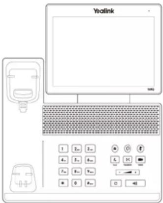
The main hardware components of the SIP VP-T49G IP phone are the touch screen and the keypad.

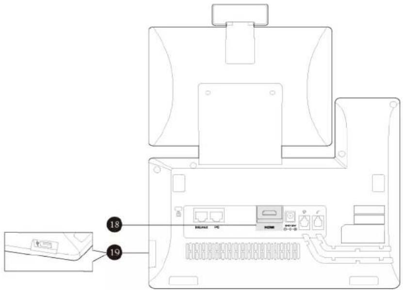
Hardware component instructions of the SIP VP-T49G IP phone are:
| Item | Description | |
| 1 | Power Indicator LED | Indicates call status, message status and phone's system status.• Receives an incoming call-Fast-flashing• Receives a voice mail or text message-Slow-flashing |
| 2 | Touch Screen | The screen is touch-sensitive. Tap to select and highlight screen items.Shows information about calls, messages, soft keys, time, date and other relevant data:Default accountCall information-caller ID, call durationIcons (for example, )Missed call list or second incoming caller informationPrompt text (for example, "Save succeeded!")Time and date |
| 3 | MESSAGE Key | Indicates and accesses voice mails. The key LED illuminates solid green when one or more voice mails are waiting at the message center.Captures screenshots during a video call. |
| 4 | HEADSET Key | Toggles and indicates the headset mode. The key LED illuminates solid green when headset mode is activated. |
| 5 | MUTE Key | Toggles and indicates mute feature. The key LED illuminates solid red when the call is muted. |
| 6 | VIDEO Key | Allows you to preview local-site video when the phone is idle.Controls the transmission of video images during calls andconferences. |
| 7 | TRANSFER Key | Transfers a call to another party. |
| 8 | Volume Key | Adjusts the volume of the handset, headset, speakerphone or ringer. |
| 9 | Speakerphone Key | Toggles and indicates the hands-free (speakerphone) mode. The key LED illuminates solid green when the hands-free (speakerphone) mode is activated. |
| 10 | REDIAL Key | Redials a previously dialed number. |
| 11 | HOLD Key | Places a call on hold or resumes a held call. |
| 12 | Keypad | Provides the digits, letters and special characters in context-sensitive applications. |
| 13 | Speaker | Provides hands-free (speakerphone) audio output. |
| 14 | Hookswitch | • Picking up the handset from the handset cradle, the hookswitch bounces and the phone connects to the line.• Laying the handset down on the handset cradle, the phone disconnects from the line. |
| 15 | Shutter Switch | Covers and uncovers the camera. |
| 16 | Camera Indicator LED | Indicates video call status and camera status.• Receives a video call-Flashing green• The camera is inserted and detected successfully on the phone-Solid green |
| 17 | Camera Lens | Provides local-site video. The better distance between camera and images you want to capture should be in the range of 0.35 meters (1 foot) to 2 meters (6 feet). |
| 18 | HDMI Port | Allows you to connect an external monitor (optional) to your phone and the video image captured from camera (both near site and far site) will also be shown on the external monitor during a video call. |
| 19 | USB2.0 Port | Allows you to connect a USB flash drive (optional) to your phone so you can display pictures on your phone, capture screenshot, and record and play back calls. |
Icon Instructions
Feature Status Icons
Icons appearing on the status bar are described in the following table:
| Icons | Description |
 | Wired network is unavailable |
 | Hands-free (speakerphone) mode |
 | Handset mode |
 | Headset mode |
 | Video/Voice Mail |
 | Text Message |
 | Auto Answer |
 | Do Not Disturb (DND) |
 | Call Forward |
 | Ringer volume is 0 |
 | Phone Lock |
 | Camera is not detected |
 | Missed Calls |
 | Bluetooth mode is on |
 | Bluetooth headset is both paired and connected |
 | Bluetooth-Enabled mobile phone is both paired and connected |
 | Wi-Fi mode is on |
| Wi-Fi is connected successfully and the signal strength is weak to strong | |
| Wi-Fi fails to connect | |
| The USB flash drive is detected | |
| External monitor is connected | |
| Ongoing Conference |
Line Key Icons
Icons appearing on the line keys are described in the following table:
| Icons | Description |
 | Voice Mail |
 | Direct Pickup |
 | Group Pickup |
 | Call Park (Park successfully; Call park idle state) |
 | Call Park (Park failed) |
 | Call Park (Call park ringing state) |
| [2BYW] | Intercom |
 | DTMFPrefix |
 | Local GroupXML Group |
 | XML Browser |
 | LDAP |
 | Conference |
 | Videoconference |
 | Forward |
 | Transfer |
 | Hold/Public HoldPrivate Hold |
 | DND |
 | ReCall |
 | SMS |
 | Record/URL Record |
 | Record/URL Record (Recording starts successfully) |
 | Multicast PagingGroup ListeningPaging List |
 | Hot Desking |
 | Zero Touch |
 | URL |
 | Phone Lock |
 | Directory |
 | Speed Dial3rd-party VMR |
 | Call Stats |
Icon indicator (associated with line)
| Icons | Description |
 | Register successfully (SIP account, private line) |
 | Register successfully (Video conference platform account) |
 | Register successfully (H.323 account) |
 | Register failed (SIP/Video conference platform account) |
 | Register failed (H.323 account) |
 (Flashing) (Flashing) | Registering (SIP/Video conference platform account) |
 (Flashing) (Flashing) | Registering (H.323 account) |
 | Register successfully (SIP account, shared line) |
 | Do Not Disturb (SIP account) |
 | Do Not Disturb (Video conference platform account) |
 | Call forward (SIP account) |
 | Call forward (Video conference platform account) |
Icon indicator (associated with mobile account)
| Icons | Description |
| [T25K] | Mobile Account (Bluetooth-Enabled mobile phone is both paired and connected) |
 | Mobile Account (Bluetooth-Enabled mobile phone fails to connect) |
 (Flashing) (Flashing) | Mobile Account (Bluetooth-Enabled mobile phone is connecting) |
Icon indicator (associated with BLF/BLF List)
| Icons | Description |
| [BCY7] | BLF/BLF list idle state |
| [ACW0](Flashing) | BLF/BLF list ringing state |
[AY22](Flashing) | BLF/BLF list callout stateBLF/BLF list talking state |
 | BLF hold state |
 | BLF list call park state |
 | BLF/BLF list failed state |
Icon indicator (associated with a shared line)
The local SCA phone indicates the phone is involved in an SCA call, while the monitoring SCA phone indicates the phone is not involved in the SCA call.
| Icon | Description |
 | The shared line is idle. |
 (for monitoring SCA phone) (for monitoring SCA phone) | The shared line is seized. |
 (Flashing) (Flashing) | The shared line receives an incoming call. |
 (Flashing) (Flashing) | The shared line is dialing. |
 | The shared line is in conversation. |
 | The shared line conversation is placed on public hold. |
 (for local SCA phone) (for local SCA phone) (for monitoring SCA phone) (for monitoring SCA phone) | The shared line conversation is placed on private hold. |
 | The shared line conversation is barged in by the other shared line party. |
| For a multi-party call, all the shared line parties participating in this call place the shared line conversation on hold. |
Other Icons
Icon indicator (associated with an active call)
| Icon | Description |
 | Call Hold (video) |
 | Call Hold (audio-only) |
 | Call Mute |
 | Call is encrypted (video) |
 | Call is encrypted (audio-only) |
 | Applying for speak |
Icon indicator (associated with call recording)
| Icons | Description |
| [42D0] | Recording box is full |
 | A call cannot be recorded |
 | Recording starts successfully |
| [XO2X] | Recording cannot be started |
 | Recording cannot be stopped |
Icon indicator (associated with call history)
| Icons | Description |
 | Received Calls (SIP/H.323 account) |
 | Placed Calls (SIP/H.323 account) |
 | Missed Calls (SIP/H.323 account) |
 | Forwarded Calls (SIP/H.323 account) |
 | Received Calls (Video conference platform account) |
 | Placed Calls (Video conference platform account) |
 | Missed Calls (Video conference platform account) |
 | Forwarded Calls (Video conference platform account) |
Icon indicator (associated with contact)
| Icons | Description |
 | The default local caller photo and local contact icon |
 | The default mobile caller photo and mobile contact icon |
 | The default Yealink Cloud caller photo and contact iconThe default YMS caller photo and contacts iconThird party device icon |
 | Permanent VMR |
 | Room system |
 | Department |
LED Instructions
Power Indicator LED
| LED Status | Description |
| Solid red | The phone is initializing. |
| Fast-flashing red | The phone is ringing. |
| Slow-flashing red | The phone receives a text message/voice mail/video mail. |
| Off | The phone is powered off.The phone is idle.The phone is busy.The call is placed on hold or is held.The call is muted. |
Note
The above introduces the default power indicator LED status. The status of the power indicator LED is configurable via web user interface. For more information, contact your system administrator.
Camera Indicator LED
| LED Status | Description |
| Solid green | The phone is powered on and the camera is properly connected to the phone.The camera is idle.The phone receives an audio-only call. |
| Flashing green | The phone receives a video call. |
| Solid red | There is an active video call.The video call is muted.The video call is held. |
| Slow-flashing red | The shutter switch is open, but the local-site video is stopped transmitting during a video call.The video call is placed on hold. |
| Off | The phone is powered off.The camera is not properly connected to the phone.The shutter switch is closed. |
User Interfaces
Two ways to customize configurations of your SIP VP-T49G IP phone:
- The user interface on the IP phone.
- The user interface in a web browser on your PC.
The hardware components keypad and touch screen constitute the phone user interface, which allows the user to execute all call operation tasks and basic configuration changes directly on the phone. In addition, you can use the web user interface to access all configuration settings. In many cases, it is possible to use either the phone user interface and/or the web user interface interchangeably. However, in some cases, it is only possible to use one or the other interface to operate the phone and change settings.
Phone User Interface
You can customize your phone by tapping to access the phone user interface. The
Advanced option is only accessible to the administrator, and the default administrator password is "admin" (case-sensitive). For more information on customizing your phone with the available options from the phone user interface, refer to Customizing Your Phone on page 65.
Note
For a better understanding of the menu structure, please refer to Appendix B - Menu Structure on page 345.
Web User Interface
In addition to the phone user interface, you can also customize your phone via web user interface. In order to access the web user interface, you need to know the IP address of your new phone. To obtain the IP address, tap ->Status on the phone when the phone is idle. Enter the IP address (e.g., http://192.168.0.10 or 192.168.0.10 for IPv4;
http://[2005:1:1:1:215:65ff:fe64:6e0a] or [2005:1:1:1:215:65ff:fe64:6e0a] for IPv6) in the address bar of a web browser on your PC. The default administrator user name and password are both "admin" (case-sensitive).
Note
The access to the Advanced settings of the Account or Network via web user interface may be blocked by the web browser (e.g., Chrome, Firefox) if you have installed "Adblock Plus plugin".
The main options you can use to customize the IP phone via phone user interface and/or via web user interface are listed in the following table:
| Options | Phone User Interface | Web User Interface |
| Status | √ | √ |
| --IPv4 | ||
| --MAC | ||
| --Firmware | ||
| --Network | ||
| --Phone | ||
| --Accounts | ||
| Basic Phone Settings | √ | |
| --Wallpaper | √ | |
| --Screen Saver | √ | |
| --Power Saving | × | |
| --Site Name | √ | |
| --Backlight | √ | |
| --Language | √ | |
| --Idle Clock | √ | × |
| --Time & Date | √ | √ |
| --Administrator Password | √ | |
| --Key as Send | √ | |
| --Phone Lock | √ | |
| --Audio Settings | ||
| --Ring Tones | √ | |
| --Key Tone | √ | |
| --Contact Management | ||
| --Local Directory | √ | |
| --Blacklist | √ | |
| --Remote Phone Book | × | |
| --Mobile Contacts | √ | × |
| --Call History Management | √ | √ |
| --Search Source List in Dialing | × | √ |
| --Bluetooth Headset | √ | √ |
| --Bluetooth-Enabled Mobile Phone | √ | |
| --DSS Keys | √ | |
| --Account Registration | √ | |
| --Dial Plan | × | |
| --Emergency Number | × | |
| --Live Dialpad | × | |
| --Hotline | √ | |
| Basic Call Features | √ | |
| --Direct IP Call | √ | |
| --Recent Call In Dialing | × | |
| --Auto Answer | √ | |
| --Auto Redial | √ | |
| --Call Completion | √ | |
| --ReCall | √ | |
| --Do Not Disturb (DND) | √ | |
| --Call Forward | √ | |
| --Call Transfer | √ | |
| --Call Waiting | √ | |
| --Conference | √ | |
| --Call Park | √ | |
| --Call Pickup | √ | |
| --Anonymous Call | √ | |
| --Anonymous Call Rejection | √ | |
| Advanced Phone Features | √ | |
| --Busy Lamp Field (BLF) | √ | |
| --BLF List | × | |
| --Call Recording | √ | |
| --Hot Desking | √ | |
| --Intercom | √ | |
| --Multicast Paging | × | |
| --Music on Hold | × | |
| --Shared Call Appearance (SCA) | × | |
| --Messages | √ | |
| SIP Account | √ | |
| --User Options | ||
| --Activation | √ | √ |
| --Label | √ | |
| --Display Name | √ | |
| --Register Name | √ | |
| --User Name | √ | |
| --Password | √ | |
| --Server Options | ||
| --SIP Server1/2 | √ | |
| --Register Port | × | |
| --Outbound Status | √ | |
| --Outbound Proxy1/2 | √ | |
| --Proxy Fallback Interval | × | |
| --NAT Status | √ | |
| Video conference platform | √ | |
| --Yealink Cloud | ||
| --PIN code | × | |
| --Please input 9-digit pincode | √ | |
| --Server | √ | |
| --Account | √ | |
| --User Name | √ | |
| --Password | √ | |
| --Server | √ | |
| --Yealink Meeting Server | ||
| --Account | √ | |
| --Password | √ | |
| --Server | √ | |
| --Outbound Proxy Server | √ | |
| --StarLeaf | ||
| --QCP | √ | |
| --Custom | ||
| --Label | √ | |
| --User Name | √ | |
| --Register Name | √ | |
| --Password | √ | |
| --Server | √ | |
| --Zoom | ||
| --Label | √ | |
| --Server | √ | |
| --Pexip | ||
| --Alias | √ | |
| --User Name | √ | |
| --Password | √ | |
| --Server | √ | |
| --Mind | ||
| --Label | √ | |
| --Server | √ | |
| --BlueJeans | ||
| --Label | √ | |
| --Server | √ | |
| H.323 Account | √ | |
| --User Options | ||
| --H.323 Protocol | √ | |
| --H.323 Account | √ | |
| --H.323 Auto Answer | × | |
| --H.323 Name | √ | |
| --H.323 Extension | √ | |
| --Server Options | ||
| --Gatekeeper Mode | √ | |
| --Gatekeeper Server1/2 | √ | |
| --Gatekeeper Port1/2 | √ | |
| --Gatekeeper Verify | √ | |
| --Gatekeeper Username | √ | |
| --Gatekeeper Password | √ | |
| --Other Options | ||
| --H.460 Active | √ | |
| --H.323 Tunneling | √ | |
| --H.235 Encryption | √ | |
| --Protocol Monitor Port | √ | |
| --DTMF Type | √ | |
| --Local Early Media | √ | |
| --H.239 | √ |
Note
The table above lists most of the feature options. Please refer to the relevant sections for more information.
Documentations
The following table shows documentations available for the SIP VP-T49G IP phone.
| Name | Contents | Where found | Language |
| Quick Start Guide | Basic call features and phone customizations | In the package | English |
| On the website | English/Chinese | ||
| User Guide | Phone/Web user interface settingsBasic call features and advanced phone features | On the website | English/Chinese |
Note
You can also download the latest documentations online: http://support.yealink.com/documentFront/forwardToDocumentDetailPage?documentId=94.
Getting Started
This chapter provides the following basic installation instructions and information for obtaining the best performance with the SIP VP-T49G IP phone. Topics include:
- Packaging Contents
- Phone Installation
• Network Connection - Phone Initialization
- Registration
- Touch Screen Display
• Navigating Menus and Fields - Gestures
• Control Center/Notification Center - Entering Data and Editing Fields
- Phone Status
- Basic Network Settings
• Wireless Network Settings
If you require additional information or assistance with your new phone, contact your system administrator.
Packaging Contents
The following components are included in your SIP VP-T49G IP phone package:
• SIP VP-T49G IP Phone
- Phone Stand

• Handset & Handset Cord


- Camera

- Ethernet Cable (2m CAT5E FTP cable)
- Quick Start Guide

- Power Adapter
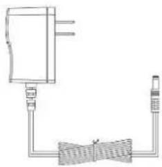
Check the list before installation. If you find anything missing, contact your system administrator.
Optional Accessories
The following items are optional accessories for your SIP VP-T49G IP phone. You need to purchase them separately if required.
• Headset YHS32/YHS33

• Yealink Extended Display Accessories: ED10
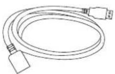
USB3.0 Cable
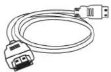
HDMI Cable

3M Dual Lock × 2

Quick Installation Guide
Note
We recommend that you use the accessories provided or approved by Yealink. The use of unapproved third-party accessories may result in reduced performance.
Phone Installation
If your phone is already installed, proceed to Phone Initialization on page 39.
This section introduces how to install the phone:
1) Insert the camera
2) Attach the stand and adjust the angle of touch screen
3) Connect the handset and optional headset
4) Connect the AC power
5) Connect the optional USB flash drive
6) Connect the optional external monitor
1) Insert the camera
![graph TD A["Handheld telephone with sensor"] --> B["Adjust Shutter Switch"] B --> C["Adjust Camera Angle"]](/content/2026/07/1418761/images/0eb1e4dab8d5a75fe0be19bcd50e2c6c0fc2667e95921867e75377cea4c9f883.jpg)
2) Attach the stand and adjust the angle of touch screen
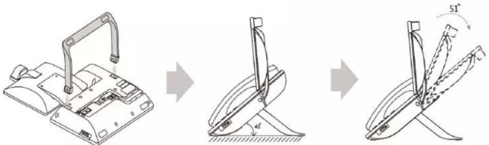
3) Connect the handset and optional headset

4) Connect the AC power
Connect the DC plug on the power adapter to the DC12V port on the phone and connect the other end of the power adapter into an electrical power outlet.

Note
Important! Do not remove power to the phone while it is updating firmware and configurations.
The IP phone should be used with Yealink original power adapter (12V/2A) only. The use of the third-party power adapter may cause the damage to the phone.
5) Connect the optional USB flash drive

When you attach a USB flash drive to your phone, the icon 📁 will display on the status bar of the touch screen. The flashing icon shows that the phone is detecting the USB flash drive. If the USB flash drive is successfully connected to the phone, the icon 📁 will stop flashing, and the touch screen will prompt "USB device connected successfully!".
Note
The USB flash drive should be purchased separately if required.
6) Connect the optional external monitor
Remove one piece of the fastener's liner, take the gap of the camera as the touchline
and stick it down; connect one end of the USB3.0 cable to the camera.
Remove the other piece of the fastener's liner and attach to the external monitor; attach the camera to the external monitor by pressing two sides of Dual Lock together. Make sure the camera is vertical and not askew otherwise the local-site video image will be crooked. You are advised to attach the camera to the external monitor whose back is straight.
- Connect the other end of USB3.0 cable to the IP phone.
- Connect one end of the HDMI cable to the HDMI port on the phone, and connect the other end to the HDMI port on the external monitor.
![graph LR A["Phone with ①"] --> B["Device with ②"] B --> C["Device with ③"] C --> D["Server with ④"]](/content/2026/07/1418761/images/05445663c22864b30dfbca559297d8dcd5d1f2dcda87cc881eba3a1af1652d57.jpg)
After you connect an external monitor to your phone, the icon will display on the status bar of the touch screen, and the touch screen will prompt "Ext. Display connected".
Note
You can adjust the camera angle by rotating it up and down, and you have to press on the back of camera to rotate it when you insert the camera to the IP phone.
If you want to insert the camera back to the IP phone and do not torn the 3M Dual Lock, please insert forcibly until the camera indicator LED illuminates solid green. And the embossing on the camera does not need to insert into the groove on the IP phone.
The Extended Display Accessories ED10 which is not included with your IP phone is required for connecting the external monitor. Contact your reseller to purchase it separately. For more information, refer to Yealink Extended Display Accessories Quick Installation Guide for SIP VP-T49G.
Network Connection
You have two options for network connection. You can select one of them according to the current office environment.
- Connecting to the wired network
- Connecting to the wireless network
Connecting to the Wired Network
You can connect your phone to a wired network.
Before connecting your phone to the wired network, it is important to note that the Wi-Fi feature should be disabled. For more information, refer to Connecting to the Wireless Network on page 39.
![graph TD A["Internal Device"] --> B["PC Connection (Optional)"] B --> C["Internet PC"] B --> D["HD/12V"] B --> E["DC/12V"]](/content/2026/07/1418761/images/5f81eb620aabb61106ca2bb1c765a6a2daddfb89bc18e1f9ceb4d813dfada291.jpg)
Note
The phone can also share the network with another network device such as a PC (personal computer). This is an optional connection. We recommend that you use the Ethernet cable provided by Yealink. The PC port may be disabled, contact your system administrator for more information.
Connecting to the Wireless Network
Yealink SIP VP-T49G IP phone supports Wi-Fi feature. You can connect your phone to a wireless network. The wireless network is more convenient and cost-effective than wired network. The PC port is unavailable when using wireless network. For more information on how to connect to a wireless network, refer to Wireless Network Settings on page 55.
Phone Initialization
After your phone is powered on, the system boots up and performs the following steps:
Automatic Phone Initialization
The phone finishes the initialization by loading the saved configuration. The touch screen displays "Welcome Initializing...Please wait" during the initialization.
DHCP (Dynamic Host Configuration Protocol)
The phone attempts to contact a DHCP server in your network to obtain valid IPv4 network settings (e.g., IP address, subnet mask, default gateway address and DNS address) by default.
Note
If your network does not use DHCP, proceed to Basic Network Settings on page 52.
Registration
Generally, your phone will be deployed with multiple other phones. In this case, your system administrator will configure the phone parameters beforehand, so that after you start up your phone, the phone will be registered and ready for use. The SIP VP-T49G IP phone supports up to 16 SIP/video conferencing platform accounts (one for Yealink Cloud/YMS account), and one H.323 account (GK account). If your phone is not registered, you may have to register it. For more information on how to register your phone, refer to Account Management on page 147, Video Conference Platform on page 288 or Registering a H.323 Account on page 333.
Touch Screen Display
Idle Screen Display
If the phone has successfully started up, the idle screen is displayed. The following figure is an example of what is displayed on the touch screen.
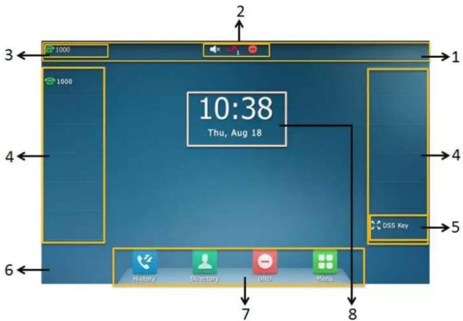
| No. | Name | Description |
| 1 | Status Bar | Displays the phone's default account and icons. |
| 2 | Icons | Icons are displayed in the middle of the status bar.For more information, refer toIcon Instructionson page 20. |
| 3 | Default Account | The label of the default account is displayed on the left of the status bar.If multiple accounts are already registered, tap andselect the desired default account. For more information, refer to Default Account on page 149. |
| 4 | Line Keys (1-11) | The idle screen displays line keys 1-11. The line keys 1-6 on the left and the line keys 7-11 on the right can be used to activate up to 11 lines.Various features can be assigned to line keys.Each line key can display the label and indicate the status of the assigned feature. |
| 5 | DSS Key | Provides a quick access the line key screen. Then, you can tap the desired line key to configure it. |
| 6 | Wallpaper | Shows the specified wallpaper, which can be customized. For more information, refer to Wallpaper on page 65. |
| 7 | Shortcut Keys | : tap this shortcut key to enter the History screen and view call history.: tap this shortcut key to enter the Directory screen and view contacts.: tap this shortcut key to toggle the DND mode or enter the custom DND configuration screen.: tap this shortcut key to enter the main menu. |
| 8 | Idle Clock | The idle clock is displayed in the center of the idle screen by default. For more information, refer to Idle Clock on page 76. |
Configuration Screen Display
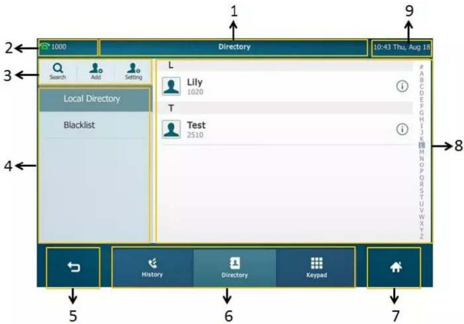
| No. | Name | Description |
| 1 | Title Area | Displays the title of the current menu screen. |
| 2 | Default Account | Displays the label of the default account.If multiple accounts are already registered, tap and select the desired default account. For more information, refer to Default Account on page 149. |
| 3 | Operation Option Area | Displays various operation options for different menu screens. |
| 4 | Menu Tree Area | Displays menu items.Tap the desired menu item to enter the corresponding configuration screen. |
| 5 | [2X8S] | Go back to the previous menu. |
| 6 | Soft Keys | Label automatically to identify their context-sensitive features. |
| 7 | [1C42] | Return to the idle screen. |
| 8 | Configuration Area | Displays configuration items of the highlighted menu item in the menu tree area. |
| 9 | Time and Date | The phone's time and date are displayed on the right of the status bar. |
Video Call Screen Display

| No. | Name | Description |
| 1 | Time and Date | The phone's time and date are displayed on the right of the status bar. |
| 2 | Line Keys (1-11) | The video call screen displays line keys 1-11. The line keys 1-6 on the left and the line keys 7-11 on the right can be used to activate up to 11 lines. Various features can be assigned to line keys. Each line key can display the label and indicate the status of the assigned feature. |
| 3 | DSS Key | Provides a quick access the line key screen. Then, you can tap the desired line key to configure it. |
| 4 |  | Displays the video on the full screen. The local-site and far-site videos only display, but the other areas are hidden. For more information on this screen display, refer to Video Call Full-Screen Display (Both Far- and Local-Site Videos Exist) on page 44. |
| 5 | Soft Keys | Label automatically to identify their context-sensitive features. |
| 6 | Far-Site Information | Shows the information (name or number) of the far site by default. |
| 7 | Call Duration Timer | Shows the duration time of current call. |
| 8 | Active Call Window | Shows the video of far site and near site. By default, a small window (near site) is located on the top-right of the touch screen, and a largerwindow (far site) is centered in the middle of the touch screen. |
| 9 | Talking Mode | Shows that you are talking using the handset, speakerphone or headset. You can alternate among the three modes during calls. |
Video Call Full-Screen Display (Both Far- and Local-Site Videos Exist)
From the video call screen, do one of the following to view full-screen video:
Tap the big size image.
Tap

The phone will enter the full screen automatically within 5 seconds during a call.

| No. | Name | Description |
| 1 | Video Display Area | Shows video in different layout. For more information, refer to Changing the Video Layout during Calls on page 174. |
| 2 | Call Duration Timer | Shows the duration time of current call. |
| 3 | Far-Site Information | Shows the information (name or number) of the far site by default. |
| 4 | Blank Area | Exits the full-screen display. |
| 5 |  | Exits the full-screen display. |
Navigating Menus and Fields
To navigate menus and fields, you can:
- Tap corresponding keys on the touch screen.
- Tap menu items, fields, and arrows on the touch screen.
- Press keys on the phone keypad.
Note
The menu system will automatically exit to the idle screen after 60 seconds of inactivity.
To operate your phone, follow these tips:
| If you want to | Action |
| Enter the main menu. | Tap  . . |
| Return to the idle screen. | Tap  |
| Go back to the previous menu. | Tap  |
| Select an item. | Tap the item. |
| Scroll through items page by page. | Drag up and down to scroll.(You can wait for the scrolling to come to a stop, or touch the screen to stop it immediately.) |
| Scroll through values for a field. | Drag up and down to scroll through values. |
| Select a value for a field. | Tap the value or scroll to the value in the pop-up dialog box. |
Gestures
To operate your phone using gestures, follow these tips:
| Gesture | Action | |
| Tap |  | Touch an item on the screen with your finger, and then lift your finger. |
| Swipe |  | Tap and move. When you want to scroll quickly, swipe your finger across the screen, either up, down, left or right. |
| Drag |  | Touch and hold, then move. To stop scrolling, stop the dragging motion. |
| Pinch Open |  | Touch the screen with two or more fingers, and then move the fingers away from each other (stretch). |
| Pinch Close |  | Touch the screen with two or more fingers, and then move the fingers towards each other (pinch). |
Control Center/Notification Center
Control center or notification center allows you to access common features or view important notifications quickly.
Swipe down from the top of the screen to enter the control center and the notification center:
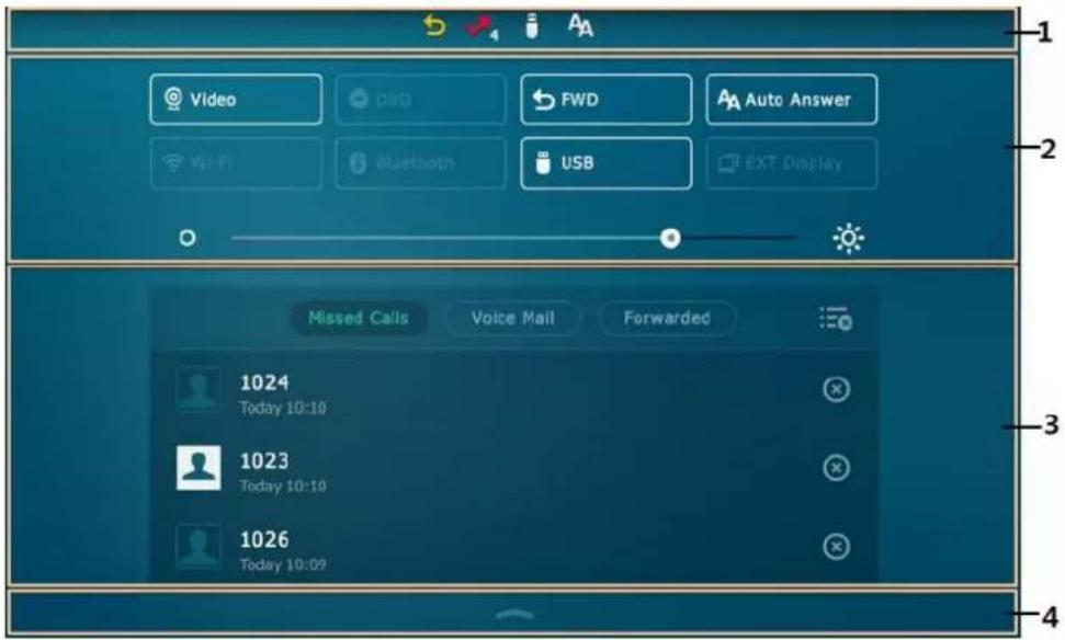
| No. | Name | Description |
| 1 | Status Bar | Displays icon to indicate a certain feature status, such as call forward, is enabled. |
| 2 | Control Center | To turn on/off common features quickly, tap corresponding icons.To adjust the screen brightness. |
| 3 | Notification Center | To view the list of miss calls, voice mail, forwarded calls quickly.To delete all records, tap = .To delete a specific record, tap = . |
| 4 |  | Tap it or swipe up from the bottom of the screen to hide this screen. |
Entering Data and Editing Fields
SIP VP-T49G IP phone provides onscreen keyboard, phone keypad and dial pad to enter data. Keypad and dial pad provides standard key layout, which enables users to use existing or familiar key positions. You can enter data and edit fields using the onscreen keyboard, phone keypad or dial pad.
Using the Onscreen Keyboard
Before using the onscreen keyboard to enter data, you need to know the function of the keys on the onscreen keyboard.
By default, the SIP VP-T49G IP phone supports English and Russia onscreen keyboard. The following takes English keyboard as an example:

| No. | Item | Description |
| 1 | 26 English Letters | Enter letters. |
| 2 | Delete Key | Delete the entered characters. |
| 3 | Enter Key | Confirm the settings.Go to the next field. |
| 4 |  | Switch to the uppercase input mode. |
| 5 |  | Switch to the numeric&symbolic input mode. |
| 6 |  | Change the language of the keyboard.You can configure custom keyboardlanguage files to provide other languages.Contact your system administrator for more information. |
| 7 | Space Key | Enter spaces. |
| 8 | Left and Right Arrow Keys | Position the cursor. |
| 9 | Four Special Characters | Enter special characters. |
| 10 |  | Hide the onscreen keyboard. |
When you tap &123, the onscreen keyboard is shown as below:
![1 ~ ! ? # % ^ & * - - = + ( ) < > [ ] { } | abc ; : " \ / 6 2 1 2 3 4 5 6 7 8 9 0 . 1 3 ← 4 → 5](/content/2026/07/1418761/images/bb1cf1beeb1a3e66843257ca93a5187112b7ba04acf36f717e07551575f4e09e.jpg)
| No. | Item | Description |
| 1 | Special Characters | Enter special characters. |
| 2 | Numbers | Enter numbers. |
| 3 | Delete Key | Delete the entered characters. |
| 4 | Enter Key | Confirm the settings.Go to the next field. |
| 5 |  | Hide the onscreen keyboard. |
| 6 |  | Switch to the alphabetical input mode. |
To use onscreen keyboard:
-
Tap the field you want to edit, the onscreen keyboard displays on the touch screen.
-
Enter the information. Do the following:
| If you want to | Action |
| Enter uppercase (A) characters, lowercase (a) characters, or a combination of uppercase and lowercase characters. | 1) If a keyboard with characters does not display, tapabcor dragabcto selectabc/ABC.2) Tap↑or drag&123to selectABC/abcto toggle between entering characters in uppercase/lowercase input mode.3) (Optional.) Tap[icon]to switch between English and Russia keyboard.4) Tap the character(s) you want to enter. |
| Enter numbers. | 1) If a keyboard with numbers does not display,tap&123or drag&123to select&123.2) Tap the number(s) you want to enter. |
| Enter special characters. | 1) If a keyboard with special characters does not display, tap&123or drag&123to select&123.2) Tap the special character(s) you want to enter. |
| Position the cursor. | Tap<or>to position the cursor.Tap to position. |
| Confirm the settings/Go to the next field. | If there is only one field or the field you are editing is the last one of the configuration, tap←to confirm the setting.If the field you are editing is not the last one of the configuration, tap←to go to the next field. |
| Delete characters one by one. | 1) Position the cursor to the right side of the text you want to delete.Tap[icon]. |
| Delete more characters at a time. | 1) Drag your finger to highlight the characters you want to delete.Tap[icon]. |
| Replace characters. | 1) Drag your finger to highlight the characters you want to delete.Tap the character(s) you want. |
For letters, special characters and number keys, you can drag the icon to select other available characters.
The original onscreen keyboard key only provide one character, you can configure a custom keyboard lme file to make the key provide more characters. Contact your administrator for more information.

The character cannot be entered until you release your finger from the key.
-
Tap to hide the onscreen keyboard.
-
(Optional.) Tap the Save soft key to accept the change.
Using the Phone Keypad and Dial Pad
Instead of using the onscreen keyboard, you can also use the keypad on your phone or dial pad on the dialing screen to enter data. The phone keypad and dial pad only provide digit keys, # key and * key.
The following displays the dial pad on dialing screen:
| 1 | 2 ABC | 3 DEF | Send |
| 4 GHI | 5 JKL | 6 MNO | |
| 7 PQRS | 8 TUV | 9WXYZ | Keyboard |
| *.@ | 0 | #SEND | DSS Key |
You can tap 📄 to use the onscreen keyboard. Keyboard
Phone Status
You can view phone status via phone user interface or web user interface.
Available information of phone status includes:
- General information (IP address, MAC address and firmware version)
• Network status (IPv4 status, IPv6 status, IP address mode and MAC address)
- IPv4 uses a 32-bit address.
- IPv6 is an updated version of the current Internet Protocol to meet the increased demands for unique IP addresses, using a 128-bit address.
- Phone status (product name, hardware version, firmware version, product ID, MAC address and device certificate status)
• Account (SIP, video conference platform or H.323) status
Note
You can view the device certificate status via phone user interface only.
You can view the H.323 status via web user interface only.
To view the phone status via phone user interface:
1.


->Status.

- Tap the desired item to view the specific information.
To view the phone status via web user interface:
- Open a web browser on your computer.
-
Enter the IP address in the browser's address bar, and then press the Enter key. (e.g., "http://192.168.0.10" for IPv4 or "http://[2005:1:1:1:215:65ff:fe64:6e0a]" for IPv6).
-
Enter the user name (admin) and password (admin) in the login page.

- Click Confirm to login.
The phone status is displayed on the first page of the web user interface.

Note
If IP mode of the phone is configured as IPv4 & IPv6, you can enter either of them in the browser's address bar to view the phone status. IPv6 is not available on all servers. Contact your system administrator for more information.
Basic Network Settings
If your phone cannot contact a DHCP server for any reason, you need to configure network settings manually. The IP phone can support either or both IPv4 and IPv6 addresses.
To configure the IP mode via phone user interface:
- Tap ->Advanced (default password: admin) ->Network->WAN Port.
- Tap the IP Mode field.
- Tap the desired value (IPv4, IPv6 or IPv4 & IPv6) in the pop-up dialog box.

- Tap the Save soft key to accept the change or ↩ to cancel.
You can configure a static IPv4 address for the IP phone. Before configuring it, make sure that the IP mode is configured as IPv4 or IPv4 & IPv6.
To configure a static IPv4 address via phone user interface:
- Tap ->Advanced (default password: admin) ->Network->WAN Port->IPv4.
- Tap the Type field.
- Tap Static IP in the pop-up dialog box.
- Enter the desired value in the IP, Subnet Mask, Gateway, Primary DNS and Secondary DNS field respectively.

- Tap the Save soft key to accept the change or ↩ to cancel.
You can configure a static IPv6 address for the IP phone. Before configuring it, make sure that the IP mode is configured as IPv6 or IPv4 & IPv6.
To configure a static IPv6 address via phone user interface:
- Tap ->Advanced (default password: admin) ->Network->WAN Port->IPv6.
- Tap the Type field.
- Tap Static IP in the pop-up dialog box.
- Enter the desired value in the IP, IPv6 IP Prefix, Gateway, Primary DNS and Secondary DNS field respectively.

- Tap the Save soft key to accept the change or ↩ to cancel.
If you are using an xDSL modem for IPv4 network connection, you can connect your phone to the Internet via PPPoE mode. Set the WAN port as a PPPoE port. The PPPoE port will perform a PPP negotiation to obtain the IP address. Contact your system administrator for the PPPoE user name and password.
To configure PPPoE via phone user interface:
- Tap ->Advanced (default password: admin) ->Network->WAN Port->IPv4.
- Tap the Type field.
-
Tap PPPoE in the pop-up dialog box.
-
Enter the PPPoE user name and password in the corresponding fields.

- Tap the Save soft key to accept the change or ↩ to cancel.
Note
The wrong network settings may result in inaccessibility of your phone and may also have an impact on your network performance. For more information on these parameters, contact your system administrator.
Wireless Network Settings
Yealink SIP VP-T49G IP phone supports Wi-Fi feature. You can connect your phone to a 2.4G/5G wireless network, and configure the country wireless channel for the IP phone. For more information, contact your system administrator.
Note
Enabling Bluetooth may degrade your wireless network connection. For improved wireless network performance, you should disable Bluetooth when it is not in use. For more information, refer to Activating the Bluetooth Mode on page 124.
Connecting to the Wireless Network
Three ways to connect SIP VP-T49G IP phone to the wireless network:
- Manually connect to an available wireless network
• Wi-Fi Protected Setup (WPS) - Manually add a wireless network
When the phone is connected to a wireless network, the Wi-Fi icon will display on the status bar of the touch screen. The Wi-Fi icon indicates the signal strength. The more green arcs you see, the stronger the signal strength is. For more information, refer to Icon Instructions on page 20.
Manually Connect to an Available Wireless Network
You can manually connect your phone to a wireless network.
To manually connect to an available wireless network via phone user interface:
-
Tap ->Basic->Wi-Fi.
-
Tap the On radio box in the Wi-Fi field.
The phone will automatically search for available wireless networks in your area.
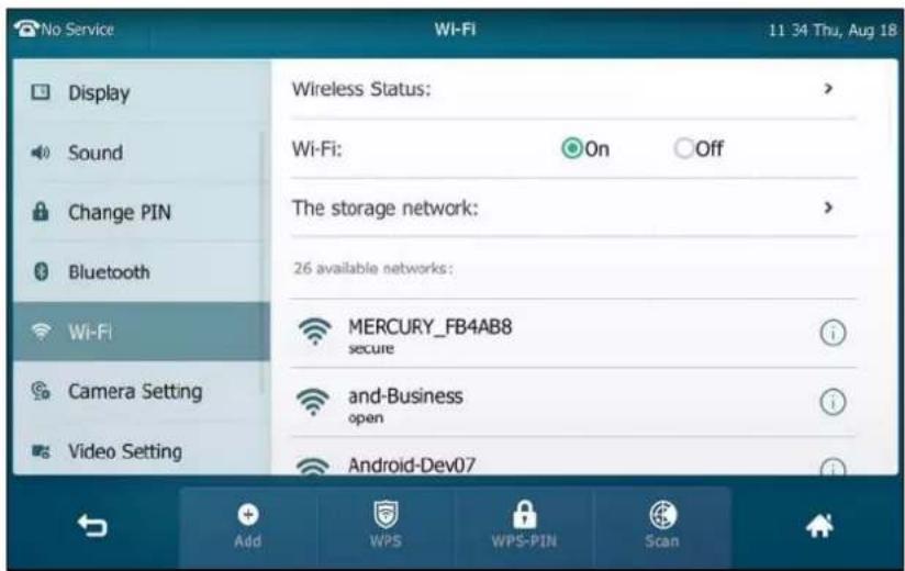
-
(Optional.) To re-search the available network, tap the Scan soft key.
-
Tap the desired wireless network (SSID) to connect to it.
You can also tap ⓘ after the desired SSID, and then tap Connect.
- If the network is secure, enter its password in the PIN field.
Contact your network administrator for the Wi-Fi password.
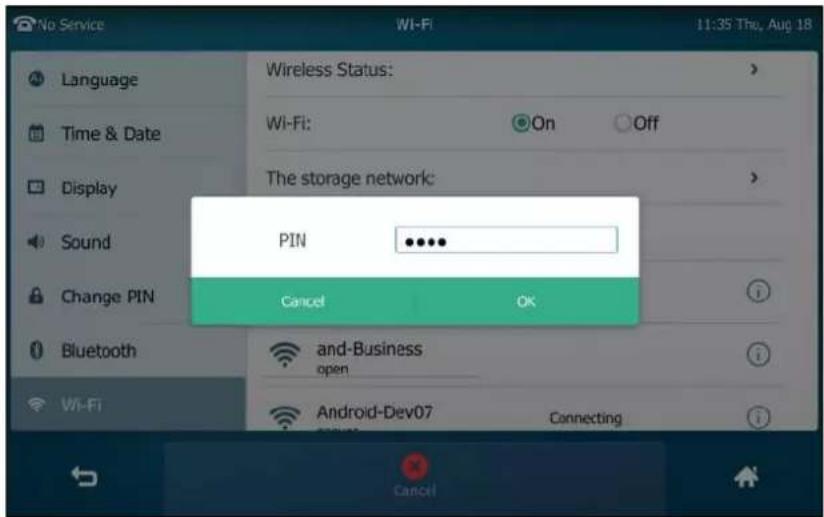
- Tap OK to connect to the wireless network.
Once the connection has completed successfully, the prompt "Connect Success." appears after the desired SSID.

The connected wireless network will be saved in the storage network list. You can tap The storage network to view all the storage wireless networks.
You can also swipe down from the top of the screen to enter the control center, and toggle Wi-Fi on. The phone will automatically search for wireless network in your area and try to connect the wireless network with highest priority which is saved in the storage network list. If there are no available wireless networks or the phone cannot connect the wireless network saved in the storage network list, the touch screen will prompt "No available Wi-Fi, go to Wi-Fi setting now". Tap OK. Repeat steps 4 to 6 to connect to the desired wireless network.
You can also manually connect your phone to an available wireless network via web user interface at the path Network->Wi-Fi.
Wi-Fi Protected Setup (WPS)
Wi-Fi Protected Setup (WPS) provides simplified mechanisms to configure secure wireless networks. WPS can automatically configure a wireless network with a network name (SSID) and strong WPA data encryption and authentication.
Two methods supported by Yealink IP phones in the Wi-Fi protected setup:
- Push Button Configuration (PBC): The user simply has to push the WPS key on both the IP phone and gateway/router to connect.
- Personal Identification Number (PIN): The user has to enter a WPS PIN generated randomly by the IP phone on the gateway/router to connect.
Push Button Configuration (PBC)
To connect to the wireless network using PBC method:
- Tap ->Basic->Wi-Fi.
2. Tap the On radio box in the Wi-Fi field.
The phone will automatically search for available wireless networks in your area.

3. Tap the WPS soft key.
The touch screen prompts "WPS has opened, please connect in 120s".
4. Long press the WPS key on your gateway/router.
Once WPS setup has completed successfully, the touch screen will prompt "Connect Success.".
Personal Identification Number (PIN)
To connect to the wireless network using PIN method:
1. Tap ->Basic->Wi-Fi.
2. Tap the On radio box in the Wi-Fi field.
The phone will automatically search for available wireless networks in your area.

3. Tap the WPS-PIN soft key.
The touch screen pops up a prompt containing a randomly generated PIN.

- Note the PIN code, and then tap OK.
The touch screen prompts "WPS has opened, please connect in 120s".
-
Enter the gateway/router address in the address bar of a web browser on your PC connected to the gateway/router.
-
Enter the user name and password in the login page.
-
Locate the WPS Wizard configuration menu.
-
Enter the PIN code in the field that allows you to setup wireless devices by using a PIN.
-
Click the corresponding button in the gateway/router's web interface to search WPS clients.
Once WPS setup has completed successfully, the touch screen will prompt "Connect Success.".
Note
Contact your gateway/router provider for more information.
Manually Add a Wireless Network
If your gateway/router has SSID broadcast disabled, it might not appear in the scanning results. In that case, you must manually add a wireless network.
To add a wireless network:
-
Tap -> Basic->Wi-Fi.
-
Tap the On radio box in the Wi-Fi field.
3. Tap the Add soft key.

- Tap the Security Mode field.
- Tap the desired value in the pop-up dialog box.
- If you select None or WEP:
1) Enter the desired profile name in the Profile Name field.
2) Enter the desired value in the SSID field.
3) Enter the desired password in the WPA Shared Key field.
- If you select WPA-PSK or WPA2-PSK:
1) Enter the desired profile name in the Profile Name field.
2) Enter the desired value in the SSID field.
3) Tap the Cipher Type field.
4) Tap the desired Cipher type (TKIP, AES or TKIP AES) in the pop-up dialog box.
5) Enter the desired password in the WPA Shared Key field.
- Tap the Save soft key to accept the change.
Viewing the Wireless Network Information
To view the wireless network information:
-
Tap ->Basic->Wi-Fi.
-
Tap ⓘ after the desired SSID to view the detailed wireless network information (e.g., Profile Name, SSID or Signal Strength).

If the IP phone is being connected to a wireless network successfully, you can also tap Wireless Status to view the connected wireless network information.

Managing the Saved Wireless Network
Once the IP phone has ever connected to wireless network successfully, the wireless network profile will be saved in The storage network list. The next time you enable Wi-Fi feature, the IP phone will be automatically connected to the wireless network which has the highest priority (the top one). Up to 5 wireless network profiles can be saved in The storage network list. If you want to add a new one when the IP phone has already saved 5 wireless network profiles, please delete the older saved profile before adding.
To manage the saved wireless network:
- Tap -> Basic->Wi-Fi.
2. Tap The storage network to view the saved wireless networks.

3. Tap ⋯ .

4. Do the following:
- To edit the wireless network profile:
1) Tap Edit.
2) Edit the desired wireless network information.
3) Tap the Save soft key.
- To change the priority of the wireless network:
1) Tap Move Up or Move Down to improve or lower the priority of the wireless network that the IP phone automatically connects to.
- To delete the saved wireless network profile:
1) Tap Delete.
If you delete your wireless network profile from your phone, you need to manually connect to it next time.
Disconnecting the Wireless Network Connection
You can disconnect the wireless network connection from your phone. After you disconnect the wireless network connection, it will still be displayed in The storage network list. So you can easily connect your phone to it again.
To disconnect the wireless network:
-
Tap -> Basic -> Wi-Fi.
-
Do one of the following:
- Tap the connected SSID (the top one) in the available networks list.
- Tap ⓘ after the connected SSID (the top one).
Tap Disconnect.

- Tap The storage network.
Tap the connected SSID.

The touch screen will prompt: Disconnect success.
You can also swipe down from the top of the screen to enter the control center, and toggle Wi-Fi off.
Disabling Wi-Fi Feature
To disable Wi-Fi feature, do one of the following:
- Tap ->Basic->Wi-Fi.
Tap the Off radio box in the Wi-Fi field.
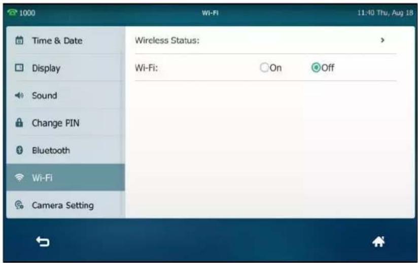
- Swipe down from the top of the screen to enter the control center, and toggle Wi-Fi off.
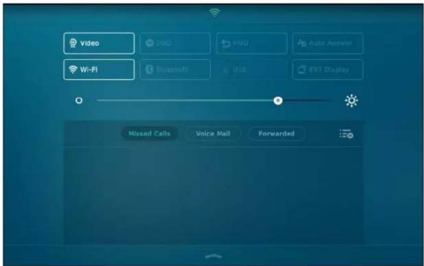
The Wi-Fi icon disappears from the touch screen.
Wi-Fi feature is configurable via web user interface at the path Network->Wi-Fi.
Customizing Your Phone
You can customize your SIP VP-T49G IP phone by personally configuring certain settings, for example, wallpaper, time & date and ring tones. You can add contacts to the phone's local directory manually or from call history. You can also personalize different ring tones for different callers.
This chapter provides basic operating instructions for customizing your phone. Topics include:
- General Settings
- Audio Settings
- Contact Management
- Call History Management
• Search Source List in Dialing
• System Customizations
If you require additional information or assistance with your new phone, contact your system administrator.
General Settings
Wallpaper
You can customize the wallpaper of the SIP VP-T49G IP phone, and can change the wallpaper image via phone user interface or web user interface. You can also upload custom pictures as wallpaper images via web user interface or using a USB flash drive.
The SIP VP-T49G IP phone supports the file format of wallpaper image in the following table:
| Format | Resolution | File Size |
| *.jpg/*.png/*.bmp/*.jpeg | 4.2 megapixels | 8MB of space should be reserved for the phone |
Changing the Wallpaper via Phone User Interface
To change the wallpaper via phone user interface:
-
Tap -> Basic->Display->Wallpaper.
-
To select the desired wallpaper, you can:
-
Tap △ or ▶.
- Tap the Wallpaper field, and then select the desired wallpaper.

- Tap the Save soft key to accept the change or ↩ to cancel.
Wallpaper is configurable via web user interface at the path Settings->Preference.
Uploading the Custom Wallpaper via Web User Interface
To upload the custom picture via web user interface:
- Click on Settings->Preference.
- In the Upload Wallpaper field, click Upload File to locate and upload the desired picture from your local system.

The web user interface prompts "Upload success!". The custom picture appears in
Wallpaper list. You can only delete the custom wallpaper by clicking Del in the Wallpaper
field.
Setting Wallpaper by Using USB Flash Drive
You can set a picture stored in your USB flash drive as the wallpaper. Before setting the picture in your USB flash drive as the wallpaper, ensure that the picture is in the USB flash drive, and the USB flash drive is connected to your phone. For more information on how to connect the USB flash drive, refer to Connect the optional USB flash drive on page 37.
To set a picture in the USB flash drive as the wallpaper:
-
Tap ->USB->Browse Photo.
-
Tap the desired picture to preview.
- Tap Set Wallpaper on the bottom of the screen.

The touch screen prompts "Set current picture as wallpaper?".
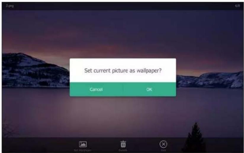
- Tap OK to accept the change or Cancel to cancel.
Wallpaper displayed on the phone user interface will change to the selected one and the custom wallpaper appears in Wallpaper list at the path ->Basic->Display->
Wallpaper.
Note
The SIP VP-T49G IP phone screen size is 8 inches (Resolution: 1280x800). If the size of the custom wallpaper doesn't meet the IP phone screen size, the wallpaper will be stretched or/and zoomed out according to the IP phone screen size.
Screen Saver
The screen saver will automatically start each time your phone is idle for a certain amount of time. The screen saver is used to blank the screen or fill it with moving images or patterns.
The screen saver will be stopped when:
- Press any key.
- Tap the touch screen.
- Pick up or hang up the handset.
• There is an incoming call.
• A new prompt (e.g., missed call, new voice mail or forwarded call).
If your phone is idle again for a specified period of time, the screen saver will start again. The time & date and certain feature status icons (e.g., auto answer, DND) will also display on the screen saver. For more information, refer to Icon Instructions on page 20.

You can configure the screen saver of SIP VP-T49G IP phone, and upload custom pictures to set up a screen saver of your picture via web user interface. You can only configure the screen saver wait time via phone user interface.
The SIP VP-T49G IP phone supports the file format of custom pictures in the following table:
| Format | Resolution | File Size |
| *.jpg/*.png/*.bmp/*.jpeg | 4.2 megapixels | 8MB of space should be reserved for the phone |
Uploading the Custom Picture via Web User Interface
To upload a custom picture via web user interface:
-
Click on Settings->Preference.
-
Select Upload Picture from the pull-down list of Screensaver Type.
-
In the Upload Screensaver field, click Upload File to locate and upload the custom picture from your local system.
This field appears only if Screensaver Type is set to Upload Picture.
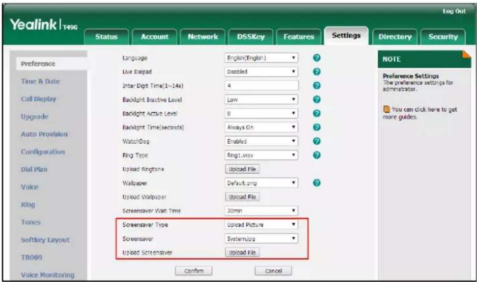
The web user interface prompts "Upload success!". The custom picture appears in
Screensaver list. The first picture in the list is System.jpg. You can only delete the custom picture by clicking Del in the Screensaver field.
Note
You can only upload one custom image at a time via web user interface.
Configuring the Screen Saver
To configure the screen saver wait time via phone user interface:
-
Tap ->Basic->Display->Screensaver.
-
Tap the Wait Time(s) field.
-
Tap the desired value in the pop-up dialog box.

- Tap the Save soft key to accept the change or ↩ to cancel.
To configure the screen saver via web user interface:
- Click on Settings->Preference.
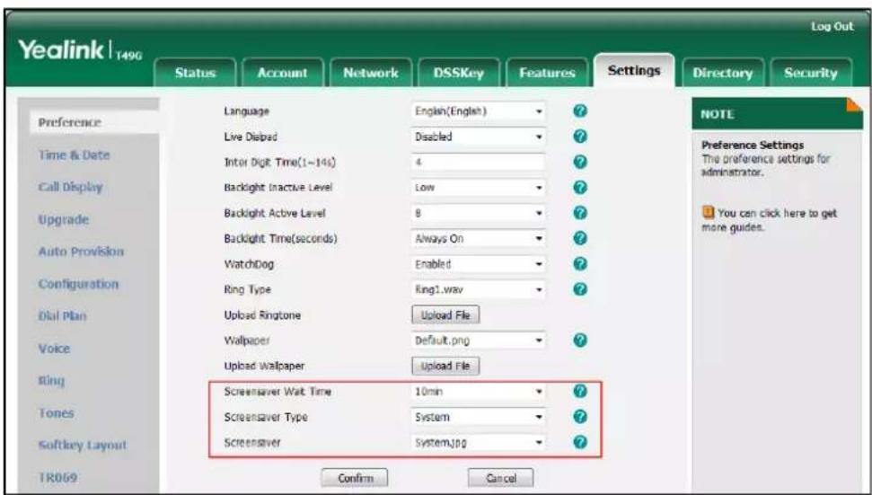
- Select the desired wait time from the pull-down list of Screensaver Wait Time.
You can set to 15s, 30s, 1min, 2min, 5min, 10min or 30min. The default value is 10min. After no activity, the phone will wait the specified period of time before displaying the screen saver.
- Select the desired screen saver type from the pull-down list of Screensaver Type.
- If you select System.
The IP phone will automatically set System.jpg as the screen saver.
- If you select Upload Picture.
The IP phone will automatically set the custom pictures you upload as the screen saver,
and display these pictures alternately.
- Click Confirm to accept the change.
Power Saving
The power saving feature is used to turn off the backlight and screen to conserve energy. The IP phone enters power-saving mode after it has been idle for a certain period of time.
The IP phone will exit power-saving mode if a phone event occurs:
- Press any key.
- Tap the touch screen.
- Pick up or hang up the handset.
• There is an incoming call.
• A new prompt (e.g., missed call, new voice mail or forwarded call).
If the screen saver is enabled on your phone, power-saving mode will still occur.
You can configure the following power-saving settings:
- Office Hour
- Idle TimeOut (minutes)
Note
Power saving is configurable via web user interface only.
Configuring the Office Hour via Web User Interface
Office Hour specifies the starting time and ending time in the office each day.
To configure the office hour via web user interface:
- Click on Settings->Power Saving.
-
Select a desired day of the week.
-
Enter the starting time and ending time respectively in the desired day field.

- Click Confirm to accept the change.
Configuring the Idle TimeOut via Web User Interface
Idle TimeOut specifies the period of time before the IP phone enters power-saving mode. The following three types of idle timeout you can configure:
• Office Hour Idle TimeOut: Configures the idle timeout for office hours.
- Off Hour Idle TimeOut: Configures the idle timeout for non-office hours.
- User Input Extension Idle TimeOut: Configures the idle timeout that applies after you use the IP phone (for example, press a key on the phone, pick up/hang up the handset or tap the touch screen).
By default, the Office Hour Idle TimeOut is much longer than the Off Hour Idle TimeOut. If you use the IP phone, the idle timeout that applies (User Input Extension Idle TimeOut or Office Hour/Off Hour Idle TimeOut) is the timeout with the highest value. If the phone has an incoming call or message, the User Input Extension Idle TimeOut is ignored.
To configure the idle timeout via web user interface:
- Click on Settings->Power Saving.
- Enter the desired value in the Office Hour Idle TimeOut field.
The default value is 120, you can set to 1-240.
- Enter the desired value in the Off Hour Idle TimeOut field.
The default value is 10, you can set to 1-10.
- Enter the desired value in the User Input Extension Idle TimeOut field.
The default value is 10, you can set to 1-20.

- Click Confirm to accept the change.
Site Name
When making a direct IP call to the other party, the site name will be displayed on the far-site LCD screen. For more information on direct IP call, refer to SIP IP Call on page 336. Site name can consist of letters, numbers or special characters.
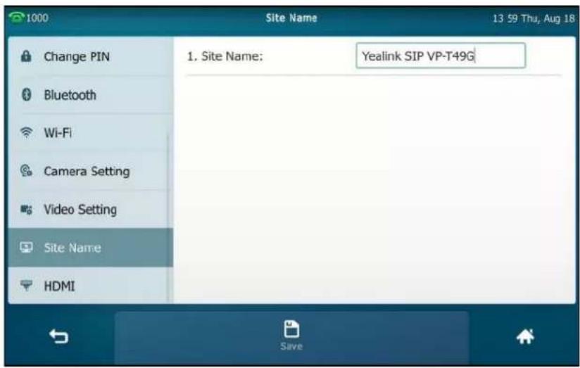
To configure the site name via phone user interface:
-
Tap ->Basic->Site Name.
-
Enter the desired name in the Site Name field.
The default site name is Yealink SIP VP-T49G.
- Tap the Save soft key.
Site name is configurable via web user interface at the path Features->General Information.
Backlight
Backlight has three options:
Backlight Active Level: The intensity of the touch screen when the phone is active. You can change the intensity of the touch screen by dragging the backlight active level slider.
Backlight Inactive Level: The intensity of the touch screen when the phone is inactive. You can select a low intensity or turn off the backlight.
Backlight Time: The delay time to change the intensity of the touch screen when the phone is inactive. You can select a desired time to change the intensity or turn on the backlight permanently.
• Always On: Backlight is on permanently.
- 15s, 30s, 60s, 120s, 300s, 600s or 1800s: Backlight is changed when the phone is inactive after the designated time (in seconds).
To configure the backlight via phone user interface:
- Tap ->Basic->Display->Backlight.
- Drag the Backlight Active Level slider.
- Tap the Backlight Inactive Level field.
- Tap the desired value in the pop-up dialog box.
-
Tap the Backlight Time field.
-
Tap the desired time in the pop-up dialog box.
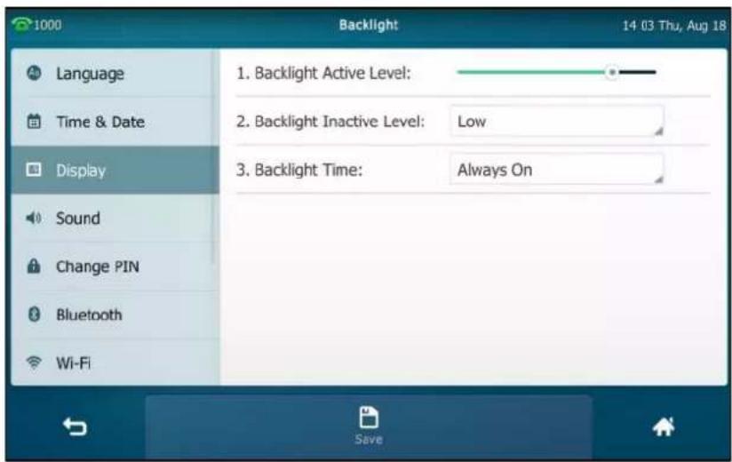
- Tap the Save soft key to accept the change or ↩ to cancel.
Backlight is configurable via web user interface at the path Settings->Preference.
Language
The default language of the phone user interface is English. If the language of your web browser is not supported by the phone, the web user interface will use English by default. You can change the language for the phone user interface and the web user interface respectively.
To change the language for the phone user interface:
- Tap ->Basic->Language.
- Drag up and down to scroll through the list of available languages.
- Tap the desired language.

- Tap the Save soft key to accept the change.
Text displayed on the phone user interface will change to the selected language.
To change the language for the web user interface:
- Click on Settings->Preference.
- Select the desired language from the pull-down list of Language.

- Click Confirm to accept the change.
Text displayed on the web user interface will change to the selected language.
Idle Clock
The idle clock is displayed in the center of the idle screen by default. You can hide the idle clock, and then the time and date will display on the right of the status bar.
To hide the idle clock via phone user interface:
- Tap ->Basic->Display->Idle Clock.
2. Tap the Off radio box in the Idle Clock Display field.

3. Tap the Save soft key.
The idle screen displays as below:

Note
The idle clock is configurable via phone user interface only.
Time & Date
The time and date are displayed in the center of screen or on the right of the status bar. You can configure the phone to obtain the time and date from the SNTP server automatically, or configure the time and date manually. If the phone cannot obtain the time and date from the Simple Network Time Protocol (SNTP) server, contact your system administrator for more information.
To configure the SNTP setting via phone user interface:
1. Tap ->Basic->Time & Date->General.
- Tap the Type field.
- Tap SNTP Settings in the pop-up dialog box.
- Tap the Time Zone field.
- Tap the time zone that applies to your area in the pop-up dialog box.
The default time zone is "+8".
- Enter the domain name or IP address of SNTP server in the NTP Server1 and NTP Server2 field respectively.
- Tap the Daylight Saving field.
- Tap the desired value in the pop-up dialog box.
- Tap the Location field.
This field appears only if Daylight Saving field is selected to Automatic.
- Tap the desired time zone name in the pop-up dialog box.
The default time zone name is "China(Beijing)".
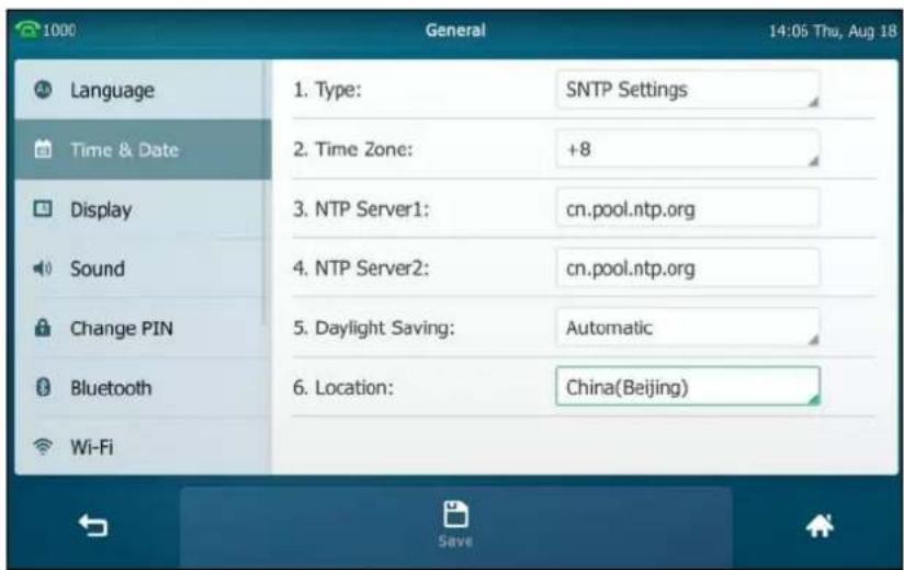
- Tap the Save soft key to accept the change or ↩ to cancel.
Note
Please refer to Appendix A - Time Zones for the list of available time zones on the IP phone.
To configure the time and date manually via phone user interface:
- Tap ->Basic->Time & Date->General.
- Tap the Type field.
-
Tap Manual Settings in the pop-up dialog box.
-
Enter the specific date and time in the corresponding fields.

- Tap the Save soft key to accept the change.
The time and date displayed on the touch screen will change accordingly.
There are 7 available date formats. For example, for the date format "WWW DD MMM", "WWW" denotes the abbreviation of the weekday, "DD" denotes the two-digit day, and "MMM" denotes the first three letters of the month.
The date formats available:
| Date Format | Example (2016-08-18) |
| WWW MMM DD | Wed, Aug 18 |
| DD-MMM-YY | 18-Aug-16 |
| YYYY-MM-DD | 2016-08-18 |
| DD/MM/YYYY | 18/08/2016 |
| MM/DD/YY | 08/18/16 |
| DD MMM YYYY | 18 Aug, 2016 |
| WWW DD MMM | Wed, 18 Aug |
To configure the date and time format via phone user interface:
-
Tap → Basic → Time & Date → Time & Date Format.
-
Tap the Date Format field.
- Tap the desired date format in the pop-up dialog box.
-
Tap the Time Format field.
-
Tap the desired time format (12 Hour or 24 Hour) in the pop-up dialog box.

- Tap the Save soft key to accept the change or ↩ to cancel.
Time and date are configurable via web user interface at the path Settings->Time & Date.
Administrator Password
The Advanced option is only accessible to the administrator. The default administrator password is "admin". For security reasons, you should change the default administrator password as soon as possible.
To change the administrator password via phone user interface:
- Tap ->Advanced (default password: admin) ->Set Password.
- Enter the current password in the Current PWD field.
- Enter the new password in the New PWD field.
- Re-enter the new password in the Confirm PWD field.
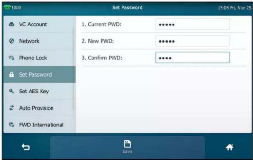
- Tap the Save soft key to accept the change or ↩ to cancel.
Administrator password is configurable via web user interface at the path Security->Password.
Key as Send
You can set the "#" key or "*" key to perform as a send key while dialing.
To configure key as send via phone user interface:
- Tap ->Features->General.
- Tap the Key as Send field.
- Tap # or * in the pop-up dialog box, or tap Disabled to disable this feature.
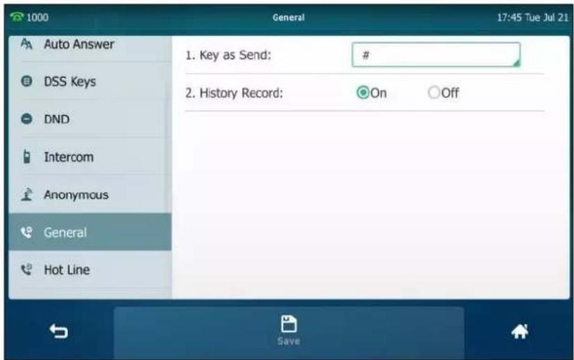
- Tap the Save soft key to accept the change or ↩ to cancel.
Key as send is configurable via web user interface at the path Features->General Information.
Phone Lock
You can lock your phone temporarily when you are not using it. This feature helps to protect your phone from unauthorized use.
When the phone is locked, the following you needed to know:
All keys and screen are locked except the HEADSET key, Volume key, digit keys, # key, * key and Speakerphone key. You are only allowed to dial emergency numbers, reject incoming calls by tapping the Reject soft key, answer incoming calls by lifting the handset, pressing the Speakerphone key, the HEADSET key or tapping the Answer soft key, and end the call by hanging up the handset, pressing the Speakerphone key or tapping the EndCall soft key.
Note
The emergency number setting, if desired, must be made before lock activation. For more information, refer to Emergency Number on page 157.
To activate the phone lock via phone user interface:
-
Tap ->Advanced (default password: admin) ->Phone Lock.
-
Tap the Lock Enable field.
-
Tap Enabled in the pop-up dialog box to enable this feature.
-
Enter the desired interval of automatic phone lock in the Lock Time Out field.
The default timeout is 0. It means the phone will not be automatically locked. You need to long press #iso to lock it immediately when the phone is idle.
If set to other values except 0 (e.g., 5), the phone will be locked when the phone is inactive in idle screen for the designated time (in seconds).
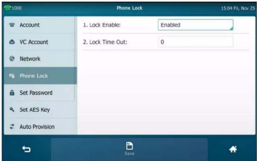
- Tap the Save soft key to accept the change.
When the phone is locked, the touch screen prompts "Phone locked." and displays the icon on the status bar of the touch screen.
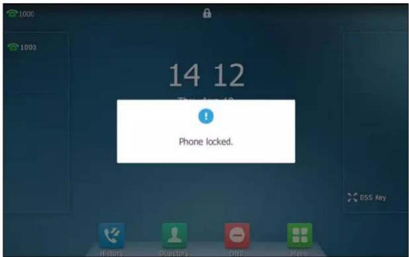
To unlock the phone, you must know the phone unlock PIN. The default phone unlock PIN is "123".
To unlock the phone via phone user interface:
- Tap the locked key, the touch screen prompts "Unlock PIN".
- Enter the PIN in the Unlock PIN field.

- Press OK to unlock the phone.
The icon 📄 disappears from the touch screen.
You can long press #180 or wait for a period of time (if configured) to lock the phone again.
Note
You can also unlock the phone by administrator password. When you enter the administrator password to unlock the phone, the phone will turn to the Change PIN screen.
To change the phone unlock PIN via phone user interface:
- Tap ->Basic->Change PIN.
- Enter the desired value in the Current PIN, New PIN and Confirm PIN field respectively.
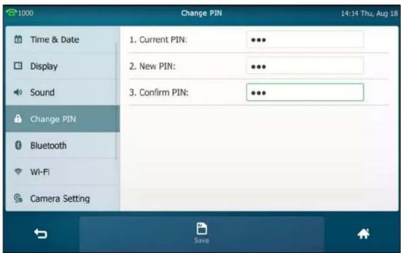
- Tap the Save soft key to accept the change or ↩ to cancel.
Note
The unlock PIN length must be within 15 digits.
To deactivate the phone lock via phone user interface:
- Tap ->Advanced (default password: admin) ->Phone Lock.
- Tap the Lock Enable field.
- Tap Disabled in the pop-up dialog box to disable this feature.

- Tap the Save soft key to accept the change.
Phone lock is configurable via web user interface at the path Features->Phone Lock.
Audio Settings
Volume
You can press the Volume key to adjust the ringer volume when the phone is idle or ringing. You can also press the Volume key to adjust the receiver volume of currently engaged audio devices (handset, speakerphone or headset) when the phone is in use.
To adjust the volume when the phone is idle:
- Press ☐ to adjust the ringer volume.

To adjust the volume when the phone is ringing:
- Press - + to adjust the ringer volume.

You can also press ⏻ to adjust the ringer volume when selecting a ring tone. For more information, refer to Ring Tones on page 86.
Note
If the ringer volume is adjusted to minimum, the icon will appear on the status bar.
To adjust the volume when the phone is during a call:
- Press ☐ to adjust the volume of currently engaged audio device (handset, speakerphone or headset).
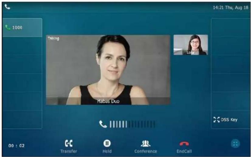
Ring Tones
Ring tones are used to indicate incoming calls. You can select different ring tones to distinguish different accounts registered on your phone, or to distinguish your phone from your neighbor's.
To select a ring tone for the phone via phone user interface:
-
Tap ->Basic->Sound->Ring Tones->Common.
-
Tap the desired ring tone.

- (Optional.) Press - + to adjust the ringer volume.
- Tap the Save soft key to accept the change or ↩ to cancel.
A ring tone for the phone is configurable via web user interface at the path
Settings->Preference->Ring Type.
To select a ring tone for the account via phone user interface:
-
Tap ->Basic->Sound->Ring Tones.
-
Tap the desired account.
-
Tap the desired ring tone.
If Common is selected, this account will use the ring tone selected for the phone.
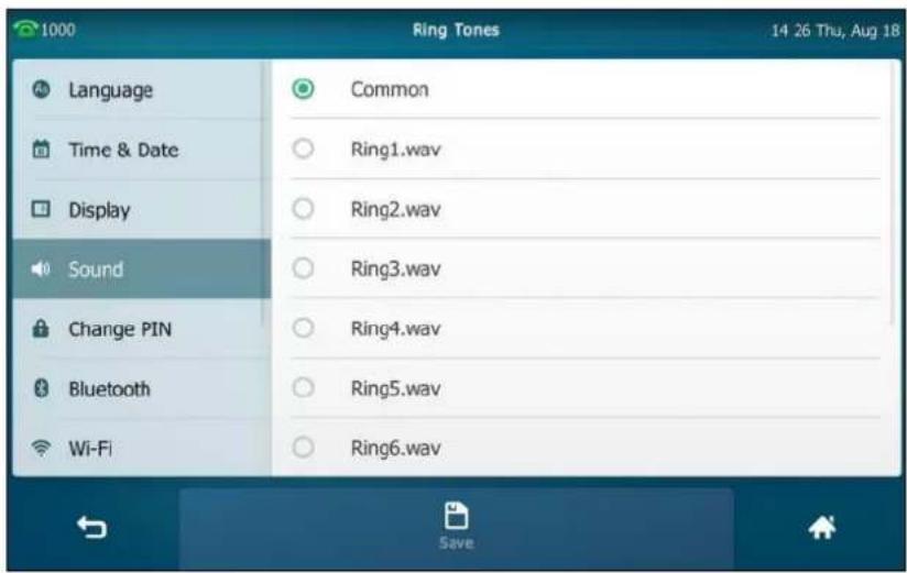
-
(Optional.) Press - + to adjust the ringer volume.
-
Tap the Save soft key to accept the change or ← to cancel.
A ring tone for the account is configurable via web user interface at the path Account->Basic->Ring Type.
To upload a custom ring tone for your phone via web user interface:
-
Click on Settings->Preference.
-
In the Upload Ringtone field, click Upload File to locate and upload a ring tone file (the file format must be *.wav) from your local system.

The web user interface prompts "Upload success!". The custom ringtone appears in Ring Type list. You can only delete the custom ringtone by clicking Del in the Ring Type field.
Note
The priority of ring tone for an incoming call on the phone is as follows: Contact ring tone (refer to Adding Contacts) >Group ring tone (refer to Adding Groups) >Account ring tone >Phone ring tone.
Single custom ring tone file must be within 8MB and total custom ring tone files must be within 20MB. Uploading custom ring tones for your phone is configurable via web user interface only.
Key Tone
If you enable key tone, the phone will produce a sound when you press the keypad.
To enable key tone via phone user interface:
- Tap ->Basic->Sound->Key Tone.
2. Tap the On radio box in the Key Tone field.

3. Tap the Save soft key to accept the change or ↩ to cancel.
Key tone is configurable via web user interface at the path Features->Audio.
Contact Management
This section provides the operating instructions for managing contacts. Topics include:
- Local Directory
- Blacklist
- Remote Phone Book
- Mobile Contacts
Local Directory
The built-in phone directory can store the names and phone numbers of your contacts. You can store up to 1000 contacts and 48 groups in your phone's local directory. You can add new groups and contacts, edit, delete or search for a contact, or simply dial a contact number from the local directory.
Adding Groups
To add a group to the local directory:
1.
Tap

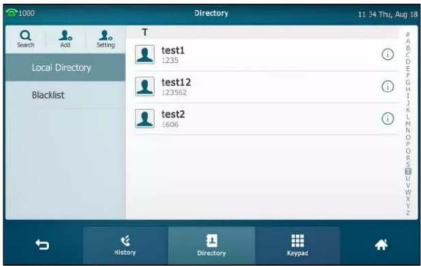
- Tap Setting.
- Tap New Group.
- Enter the desired group name in the highlighted field.

- Tap √ to accept the change.
-
Tap ♩ to specify a ring tone for the group.
-
Tap the desired ring tone in the pop-up dialog box.

If Auto is selected, this group will use the ring tone according to the priority: Contact ring tone (refer to Adding Contacts) >Account ring tone (refer to Ring Tones) >Phone ring tone (refer to Ring Tones). If a specific ring tone is selected, this group will use the ring tone according to the priority: Contact ring tone (refer to Adding Contacts) >Group ring tone.
- Tap OK to accept the change.
You can also edit or delete any newly added contact groups.
Editing Groups
To edit a group in the local directory:
1.
Tap

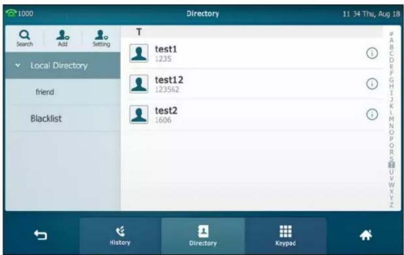
-
Tap Setting.
-
Tap the desired group.
-
Tap after the group name.

- Edit the group name in the highlighted field.
- Tap √ to accept the change.
Deleting Groups
To delete a group from the local directory:
- Tap

- Tap Setting.
- Tap ☐ before the desired group name.
The touch screen prompts the following warning:
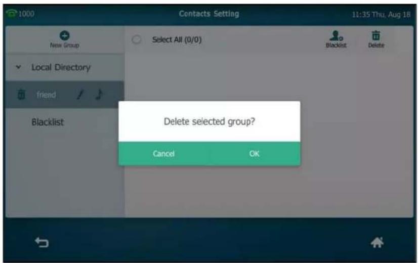
- Tap OK to accept the change or Cancel to cancel.
Adding Contacts
You can add contacts to the local directory in one of the following ways:
- Manually
- From call history
• From a remote phone book
Adding Contacts Manually
To add a contact to the local directory manually:
- Tap

- Tap Add.
If you want add a contact to the specified contact group, you can tap the contact group
first, and then tap Add.
- Enter the name and the office, mobile or other numbers in the corresponding fields.
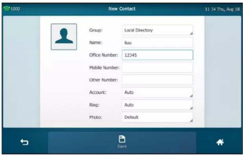
- Tap the Account field.
- Tap the desired account in the pop-up dialog box.
If Auto is selected, the phone will use the default account when placing calls to the contact from the local directory.
- Tap the Ring field.
- Tap the desired ring tone in the pop-up dialog box.
If Auto is selected, this contact will use the ring tone according to the priority: Group ring tone (refer to Adding Groups) >Account ring tone (refer to Ring Tones) >Phone ring tone (refer to Ring Tones).
- Tap the Photo field.
- Tap the desired photo in the pop-up dialog box.
- Tap the Save soft key to accept the change or ↩ to cancel.
Note
If the contact already exists in the directory, the touch screen will prompt "Contact name existed!".
Adding Contacts from Call History
To add a contact to the local directory from call history:
- Tap
-
Drag up and down to view the list of history.
-
Tap ⓘ after the desired entry.

- Tap Add.
- Edit the corresponding fields.

- Tap the Save soft key to accept the change.
The entry is successfully saved to the local directory.
Adding Contacts from a remote phone book
To add a contact to the local directory from a remote phone book:
- Tap → Remote Phone Book or tap → Directory → Remote Phone Book to enter the remote phone book.
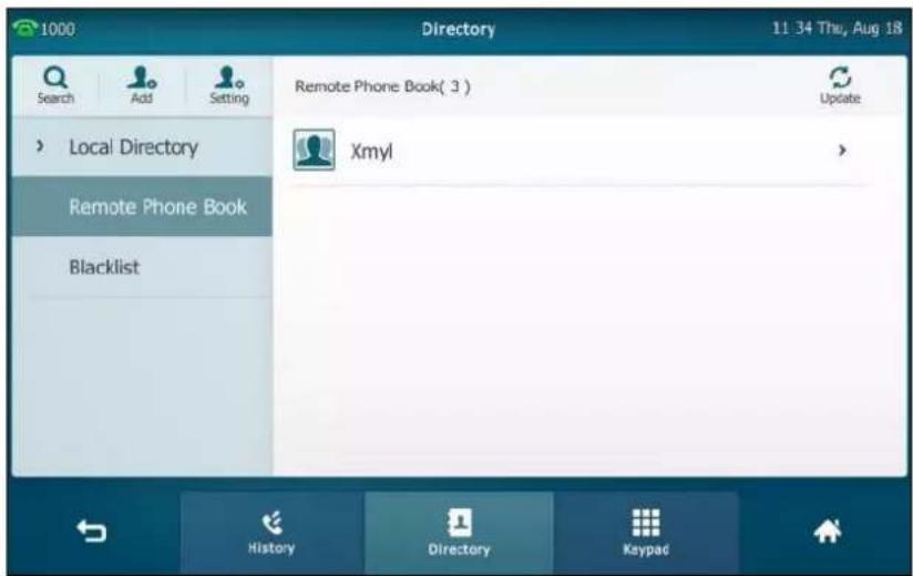
- Tap the desired remote phone book.
The phone then connects to the remote phone book and proceeds to load it. The contacts in the remote phone book are displayed on the touch screen.
- Tap ⓘ after the desired contact in the remote phone book.

- Tap Add.
5. Edit the corresponding fields.

6. Tap the Save soft key to save the contact to the local directory.
If the contact already exists in the local directory, the touch screen will prompt "Overwrite the original contact?". Tap OK to overwrite the original contact in the local directory or Cancel to cancel.
For more information on remote phone book operation, refer to Remote Phone Book on page 109.
Editing Contacts
To edit a contact in the local directory:
1. Tap

2. Tap ⓘ after the desired contact.
If the contact was added to a specified contact group, you can tap the contact group first, and then tap ⓘ after the desired contact.
- Tap the desired field to edit the contact information.

You can tap ◀ or ▶ to change the contact you want to edit.
- Tap the Save soft key to accept the change or ↩ to cancel.
Deleting Contacts
To delete a contact from the local directory:
- Tap


- Tap ⓘ after the desired contact.
If the contact was added to a specified contact group, you can tap the contact group first, and then tap ⓘ after the desired contact.
- Tap Delete.
The touch screen prompts the following warning:

- Tap OK to accept the change or Cancel to cancel.
To delete all contacts:
1.
Tap


- Tap Setting.
- Tap the Select All checkbox.
- Tap Delete.
The touch screen prompts the following warning:

- Tap OK to accept the change or Cancel to cancel.
Uploading Contact Photos
To upload a new custom photo for the contact via web user interface:
- Click on Directory->Local Directory.
- Click Upload Photo, and then locate and upload a photo file from your local computer. The web user interface prompts "Upload success!".
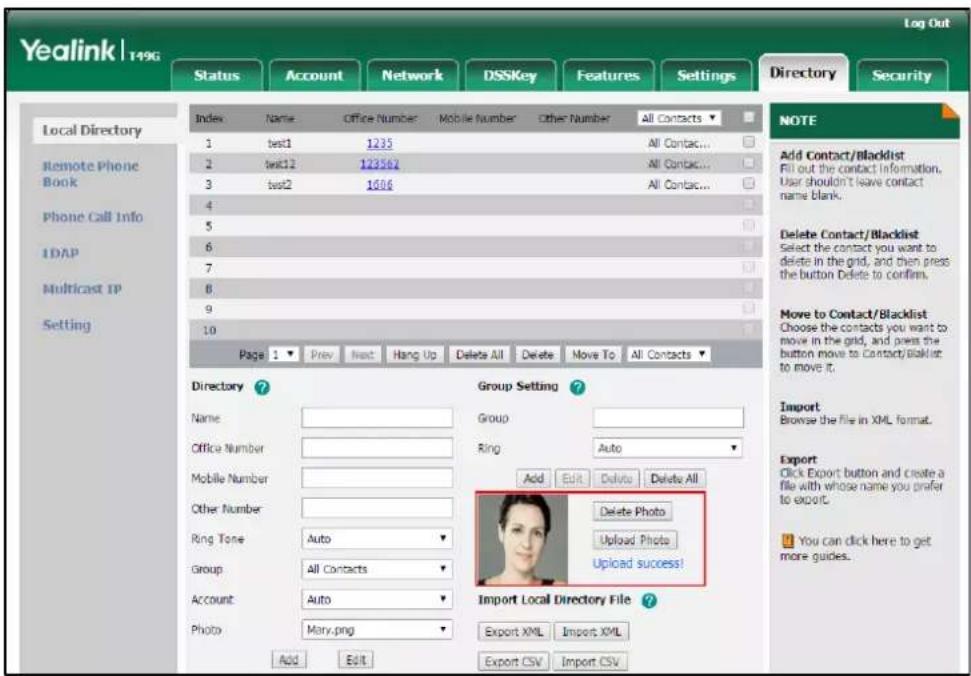
You can click Delete Photo to delete the custom photo.
Note
The phone only supports *.png, *.jpg and *.bmp format files. The file size must be less than 2M. You can only delete custom photos.
To change the custom photo for the contact via web user interface:
- Click on Directory->Local Directory.
- Click the desired contact you want to edit.
- Select the desired photo from the pull-down list of Photo.

- Click Edit to accept the change.
When you place a call to the contact or receive a call from the contact, the touch screen will display the contact photo.

Placing Calls to Contacts
To place a call to a contact from the local directory:
1.
Tap

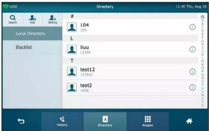
- If the contact was added to a specified contact group, you can tap the contact group first, and then do one of the following:
- Tap the desired contact.
- If only one number for the contact is stored in the local directory, the number is being dialed out.
- If multiple numbers for the contact are stored in the local directory, tap the desired number to dial out.
Tap ⓘ after the desired contact.
- If only one number for the contact is stored in the local directory, tap Send to dial out the number.
- If multiple numbers for the contact are stored in the local directory, tap Send to display a list of numbers.
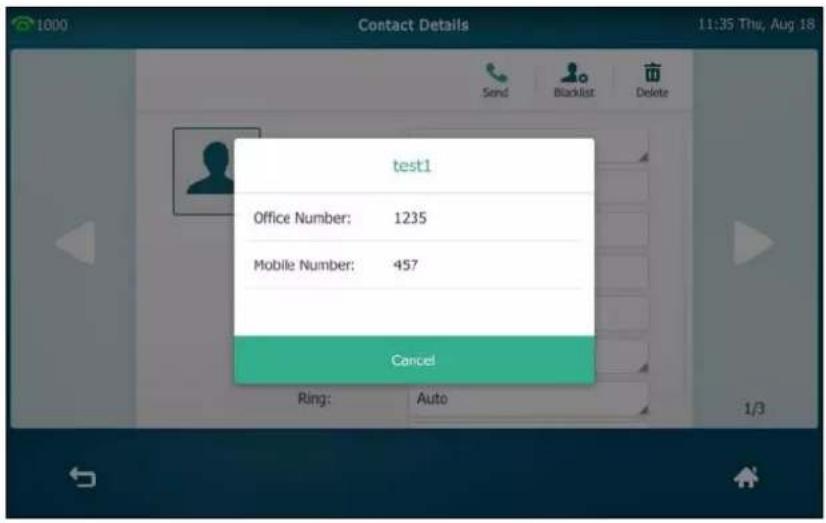
Tap the desired number to dial out.
Searching for Contacts
To search for a contact in the local directory:
- Tap
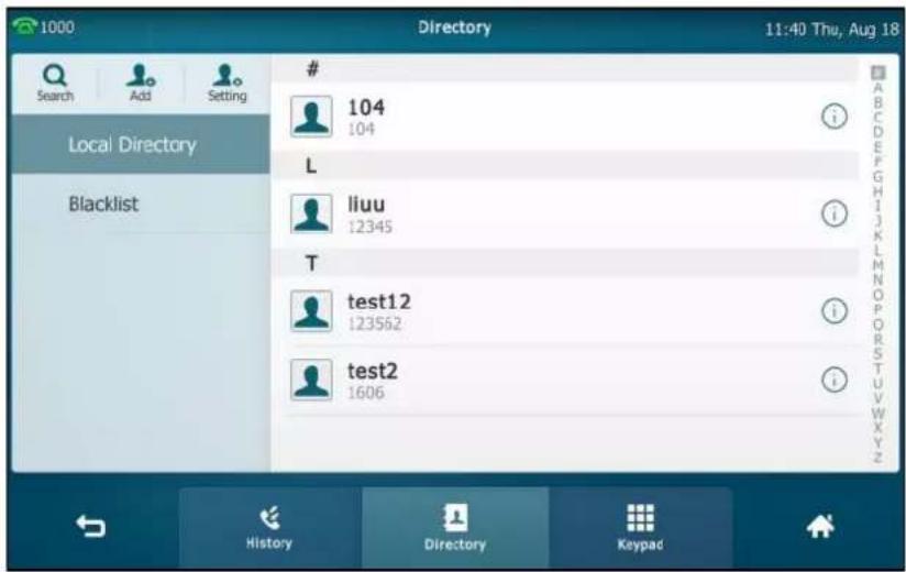
- Do one of the following :
Tap Search.
Enter a few continuous characters of the contact name or continuous numbers of the contact number (office, mobile or other number) using the onscreen keyboard.

The contacts whose name or phone number matches the characters entered will appear on the touch screen. You can dial from the result list.
Tap the desired letter (e.g., T) along the right side to jump to contacts whose names start with T or t.
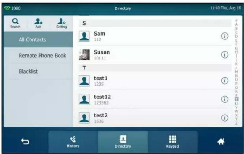
Drag up and down to select the desired contact to view or dial out.
Importing/Exporting Contact Lists
You can manage your phone's local directory via phone user interface or web user interface. But you can only import or export the contact list via web user interface.
To import an XML contact list file via web user interface:
- Click on Directory->Local Directory.
- Click Import XML to locate and upload a contact list file (the file format must be *.xml)
from your local system.

The web user interface prompts "The original contact will be covered, Continue?".
- Click OK to complete importing the contact list.
To import a CSV contact list file via web user interface:
- Click on Directory->Local Directory.
- Click Import CSV to locate and upload a contact list file (the file format must be *.csv) from your local system.
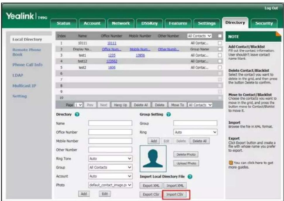
3. (Optional.) Check the Show Title checkbox.
It will prevent importing the title of the contact information which is located in the first line of the CSV file.
4. (Optional.) Check the Delete Old Contacts checkbox.
It will delete all existing contacts while importing the contact list.

5. Click Import to complete importing the contact list.
To export a contact list via web user interface:
- Click on Directory->Local Directory.
- Click Export XML (or Export CSV).
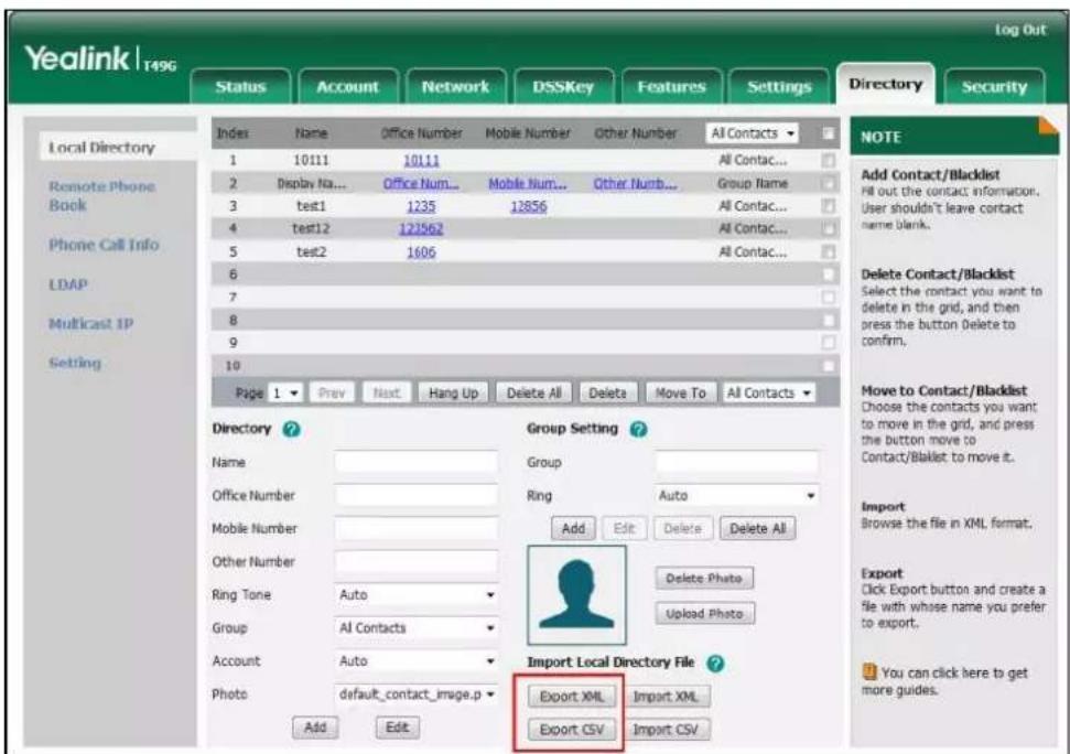
- Click Save to save the contact list to your local system.
Note
Importing/exporting contact lists is available via web user interface only.
Blacklist
The built-in phone directory can store names and phone numbers for a blacklist. You can store up to 30 contacts; add, edit, delete or search for a contact in the blacklist directory, and even call a contact from the blacklist directory. Incoming calls from the blacklist directory contacts will be rejected automatically.
For operating instructions on editing, deleting, placing calls to and/or searching for contacts in the blacklist directory, refer to the operating instructions of Editing Contacts on page 97, Deleting Contacts on page 98, Placing Calls to Contacts on page 102 and/or Searching for Contacts on page 103.
To add a contact to the blacklist directory manually:
1.
Tap

->Blacklist.

-
Tap Add.
-
Enter the contact's name and the office, mobile or other numbers in the corresponding fields.
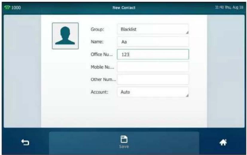
- Tap the Account field.
- Tap the desired account in the pop-up dialog box.
If Auto is selected, the phone will use the default account when placing calls to the contact from the blacklist directory.
- Tap the Save soft key to accept the change or ↩ to cancel.
To add a contact to the blacklist directory from the local directory:
- Tap
- Tap ⓘ after the desired contact.
If the contact was added to a specified contact group, you can tap the contact group first, and then tap ⓘ after the desired contact.
- Tap Blacklist.
The touch screen prompts the following warning:

- Tap OK to accept the change.
Remote Phone Book
You can add contacts to the local directory, search for a contact, or simply dial a contact number from the remote phone book.
You can configure your new phone to access up to 5 remote phone books. The phone supports up to 3000 remote phone book entries. For the access URL of the remote phone book, contact your system administrator.
For operating instructions on placing calls to and/or searching for contacts in the remote phone book, refer to the operating instructions of Placing Calls to Contacts on page 102 and/or
Searching for Contacts on page 103.
Configuring an Access URL
To configure an access URL for a remote phone book via web user interface:
- Click on Directory->Remote Phone Book.
- Enter the access URL in the Remote URL field.
- Enter the name in the Display Name field.

- Click Confirm to accept the change.
Note
An access URL for a remote phone book is configurable via web user interface only.
Accessing the Remote Phone Book
To access your remote phone book via phone user interface:
- Tap -> Remote Phone Book or tap -> Directory-> Remote Phone Book to enter the remote phone book.
- Tap the desired remote phone book.
The phone then connects to the remote phone book and proceeds to load it. The contacts in the remote phone book are displayed on the touch screen.
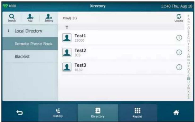
You can tap ↩ to back to the previous interface.
Incoming/Outgoing Call Lookup
You can enable the phone to present the caller/callee identity stored in the remote phone book when receiving/placing a call.
To configure incoming/outgoing call lookup and update time interval via web user interface:
- Click on Directory->Remote Phone Book.
- Select Enabled from the pull-down list of Incoming/Outgoing Call Lookup.
- Enter the desired refresh period in the Update Time Interval(Seconds) field.
The default value is 21600.
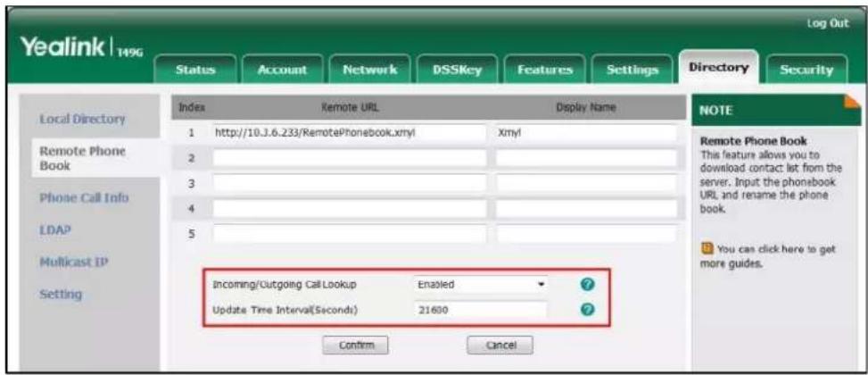
- Click Confirm to accept the change.
Mobile Contacts
The first time your IP phone pairs and connects to your Bluetooth-enabled mobile phone, you will be asked if you would like to sync phone contacts temporarily. If allowed, the phone contacts will be imported to the mobile contacts directory of your IP phone. For more information, refer to Bluetooth-Enabled Mobile Phone on page 129.
You can add a contact to the local directory or blacklist directory from mobile contacts. You cannot add a contact to the mobile contacts directory on your IP phone.
Note
If you disconnect the Bluetooth-enabled mobile phone from IP phone or disable the IP phone to sync phone contacts, the mobile contacts directory will disappear.
For operating instructions on placing calls to and/or searching for contacts in the mobile contacts directory, refer to the operating instructions of Placing Calls to Contacts on page 102 and/or Searching for Contacts on page 103.
To add a contact to the local directory from mobile contacts directory:
- Tap ->Mobile Contacts.
- Drag up and down to view the list of Mobile Contacts.
- Tap ⓘ after the desired entry.

- Tap Add.
5. Edit the corresponding fields.

6. Tap the Save soft key to accept the change.
The entry is successfully saved to the local directory.
To add a contact to the blacklist directory from the mobile contacts directory:
- Tap ->Mobile Contacts.
- Tap ⓘ after the desired contact.
- Tap Blacklist.
- Edit the corresponding fields.

5. Tap the Save soft key to accept the change.
The entry is successfully saved to the blacklist directory.
Note
The contact that be added to the local directory or blacklist directory will not disappear, after you disconnect the mobile phone from the IP phone.
To update the mobile contacts directory:
1. Tap ->Mobile Contacts.
2. Tap Update.
The touch screen will prompt "Updating, please wait...", you need to authorize the IP phone to sync the contacts temporarily on the mobile phone.

After updating, the contacts you add, edit, delete on the mobile phone will sync to the mobile contacts directory.
Note
If you disconnect the mobile phone from IP phone while the IP phone is updating the mobile phone book. The touch screen will prompt "Fail to download mobile contacts!", and the mobile contacts directory will disappear from the IP phone directory list.
Call History Management
The SIP VP-T49G IP phone maintains call history lists of Missed calls, Placed calls, Received calls and Forwarded calls. Each call history list supports up to 100 entries. You can view call history, place a call, add a contact or delete an entry from the call history list.
History record feature is enabled by default, if you don't want to save the call history, you can disable the feature.
Viewing History Records
To view call history:
1. Tap
The touch screen displays all call records.
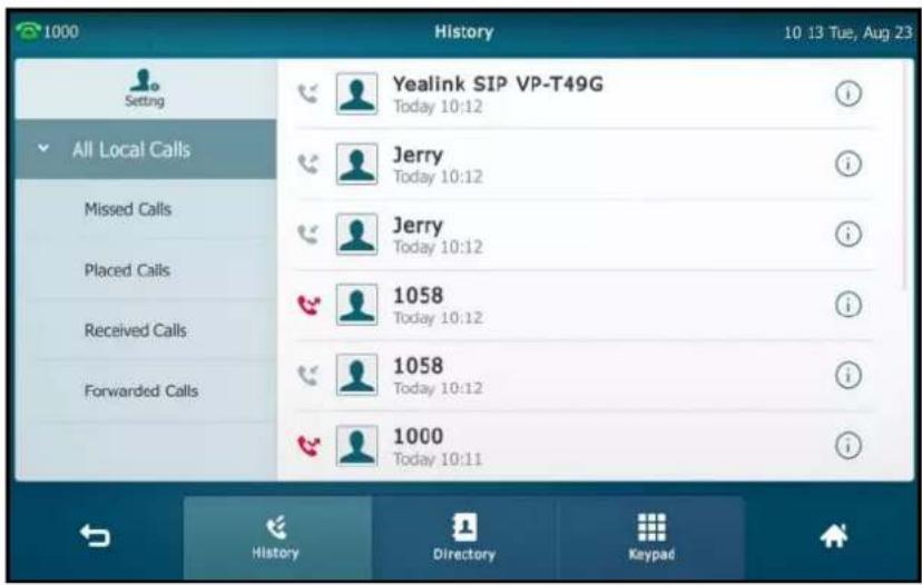
- Drag up and down to scroll.
You can tap Missed Calls, Placed Calls, Received Calls or Forwarded Calls to view entries in each call list directly.
- Tap ⓘ after the desired entry.
The detailed information of the entry appears on the touch screen.
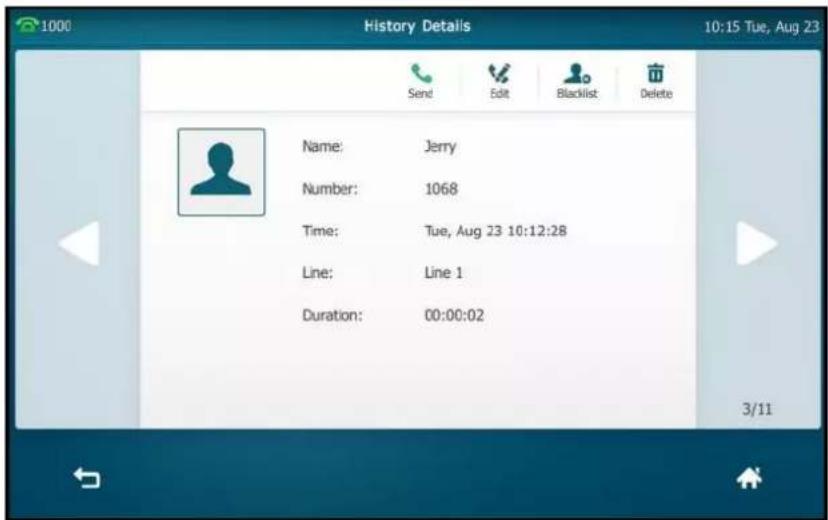
Placing a Call from History Records
To place a call from the call history list:
1. Tap
The touch screen displays all call records.
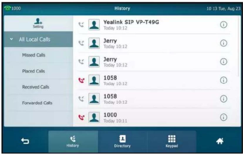
- Drag up and down to scroll.
You can tap Missed Calls, Placed Calls, Received Calls or Forwarded Calls to view entries in each call list directly.
- Tap the desired entry.
Adding a Contact to the Local Directory/Blacklist
To add a contact to the local directory (or blacklist directory) from the call history list:
1. Tap
The touch screen displays all call records.
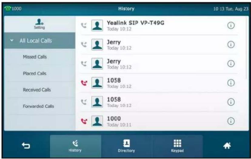
- Drag up and down to scroll.
You can tap Missed Calls, Placed Calls, Received Calls or Forwarded Calls to view entries in each call list directly.
- Tap ⓘ after the desired entry.
- Tap Add (or Blacklist).
- Enter the desired values in the corresponding fields.
- Tap the Save soft key to accept the change or ↩ to cancel.
For more information, refer to Contact Management on page 89.
Deleting History Records
To delete an entry from the call history list:
1. Tap
The touch screen displays all call records.

- Drag up and down to scroll.
You can tap Missed Calls, Placed Calls, Received Calls or Forwarded Calls to view entries in each call list directly.
-
Tap ⓘ after the desired entry.
-
Tap Delete.
The touch screen prompts the following warning:
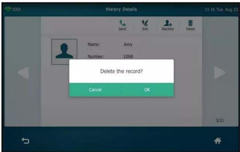
- Tap OK to confirm the deletion or Cancel to cancel.
To delete all entries from the call history list:
1.
Tap

The touch screen displays all call records.
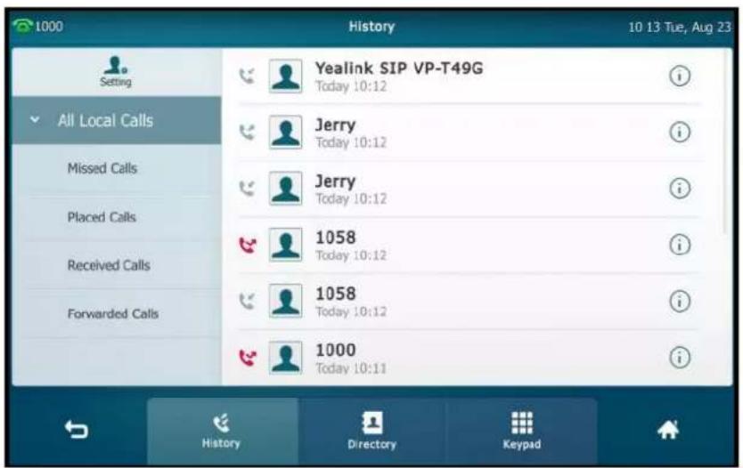
- Drag up and down to scroll.
You can tap Missed Calls, Placed Calls, Received Calls or Forwarded Calls to view entries in each call list directly.
- Tap Setting.
- Tap the Select All checkbox.

- Tap Delete.
The touch screen prompts the following warning:

- Tap OK to confirm the deletion or Cancel to cancel.
Disabling History Records
To disable history record via phone user interface:
- Tap ->Features->General.
- Tap the Off radio box in the History Record field.
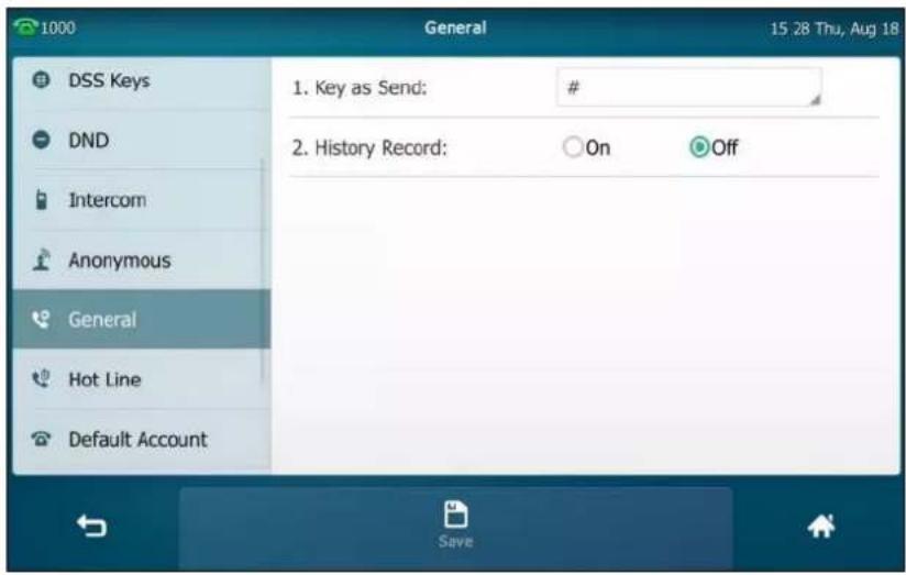
- Tap the Save soft key to accept the change or ↩ to cancel.
Search Source List in Dialing
You can search for a contact from the desired lists when the phone is on the dialing screen. The lists can be Local Directory, History, Remote Phone Book, LDAP and Cloud Directory.
To configure search source list in dialing via web user interface:
- Click on Directory->Setting.
- In the Search Source List In Dialing block, select the desired list from the Disabled column and click □.
The selected list appears in the Enabled column.
- Repeat the step 2 to add more lists to the Enabled column.
- (Optional.) To remove a list from the Enabled column, select the desired list and then click . . .
- To adjust the display order of the enabled list, select the desired list, and click or □.

- Click Confirm to accept the change.
The touch screen will display search results in the adjusted order.
Note
Search source list in dialing is configurable via web user interface only.
To search for an entry in the enabled search source lists:
- Pick up the handset, press the Speakerphone key or tap the line key.
- Enter a few continuous characters of the entry's name or continuous numbers of the entry's phone number (office, mobile or other number).
The entries in the enabled search source lists whose name or phone number matches the characters entered will appear on the touch screen.
You can tap the desired entry to place a call to the entry.

Note
If you connect a Bluetooth-Enabled mobile phone to the IP phone, and enable the IP phone to sync phone contacts. The IP phone will first search the contacts in the mobile contacts directory then placed calls list. For more information, refer to Mobile Contacts on page 111.
System Customizations
Headset Use
If you want to use a wired headset, physically connect your headset and activate the headset mode for use. For more information on physically connecting a headset, refer to Phone Installation on page 35.
If you want to use a wireless headset, activate the Bluetooth mode and then pair and connect the Bluetooth headset with your phone. For more information on using a Bluetooth headset, refer to Bluetooth Headset on page 123.
This section provides an introduction to wired headset use.
Note
There are three types of headsets for SIP VP-T49 IP phones: the wired headset, EHS headset and Bluetooth headset. You can connect up to three types of headsets at once. And if you press the HEADSET key, the IP phone will use the headset according to the priority: Bluetooth headset >EHS headset >wired headset.
Headset Mode Activation/Deactivation
To activate the headset mode:
- Press 📄 on the phone.
The HEADSET key LED illuminates solid green, and the icon 📄 appears on the status bar.
When you tap the line key or the Answer soft key to answer an incoming call, the call is connected to your headset automatically. For more information on using the headset to answer a call, refer to Answering Calls on page 165.
With the handset on-hook, enter the desired number and tap the Send soft key, the phone will then place a call using the headset automatically. For more information on using the headset to place a call, refer to Placing Calls on page 162.
To deactivate the headset mode:
- Press 📄 again on the phone.
The HEADSET key LED goes out, and the icon disappears from the touch screen.
Headset Prior
You can use headset in priority when headset prior feature is enabled. This feature is especially useful for permanent or full-time headset users.
To enable headset prior via web user interface:
- Click on Features->General Information.
- Select Enabled from the pull-down list of Headset Prior.

- Click Confirm to accept the change.
To use headset prior, you should activate the headset mode in advance:
- Physically connect the headset.
- Press Ⓠ to activate the headset mode.
Note

If headset prior is enabled, the headset mode will not be deactivated until you press the HEADSET key again.
If headset prior is disabled, the headset mode can be deactivated by pressing the Speakerphone key or the HEADSET key.
Headset prior is configurable via web user interface only.
Dual Headset
You can use two headsets when dual headset feature is enabled. To use this feature, you must physically connect headsets to the headset jack and handset jack respectively. Once the phone connects to a call, the headset connected to the headset jack will have full-duplex capabilities, while the one connected to the handset jack will only be able to listen.
To enable dual headset via web user interface:
- Click on Features->General Information.
- Select Enabled from the pull-down list of Dual-Headset.
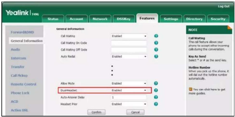
- Click Confirm to accept the change.
Note
Dual headset is configurable via web user interface only.
Bluetooth Headset
The SIP VP-T49G IP phone supports Bluetooth. Bluetooth enables low-bandwidth wireless connections within a range of 10 meters (32 feet). The best performance is in the 1 to 2 meters (3 to 6 feet) range.
You can activate/deactivate the Bluetooth mode, and then pair and connect the Bluetooth headset with your phone. You can pair up to countless Bluetooth headsets with your phone; however, only one headset can be connected at a time. You can also disconnect and delete your Bluetooth headset from the phone.
Activating the Bluetooth Mode
To activate the Bluetooth mode via phone user interface:
-
Tap ->Basic->Bluetooth.
-
Tap the On radio box in the Bluetooth field.
The IP phone scans the available Bluetooth headset automatically.
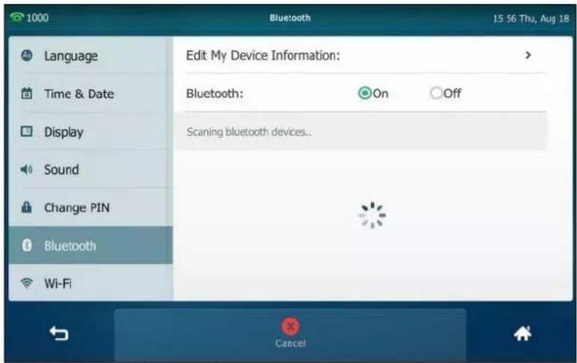
The touch screen displays the Bluetooth device information (device name and MAC address).
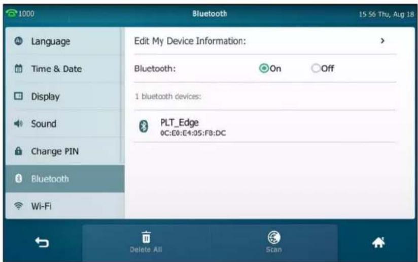
You can also swipe down from the top of the screen to enter the control center, and toggle Bluetooth on.
Pairing and Connecting the Bluetooth Headset
Before you pair a Bluetooth headset, check the indicator on the Bluetooth headset to make sure that the Bluetooth headset is discoverable. For more information, refer to the documentation from the Bluetooth headset manufacturer.
To pair and connect your Bluetooth headset to your phone:
-
Tap ->Basic->Bluetooth.
-
Tap the On radio box in the Bluetooth field.
If there is no Bluetooth devices found on the touch screen, tap the Scan soft key to search for the Bluetooth device.
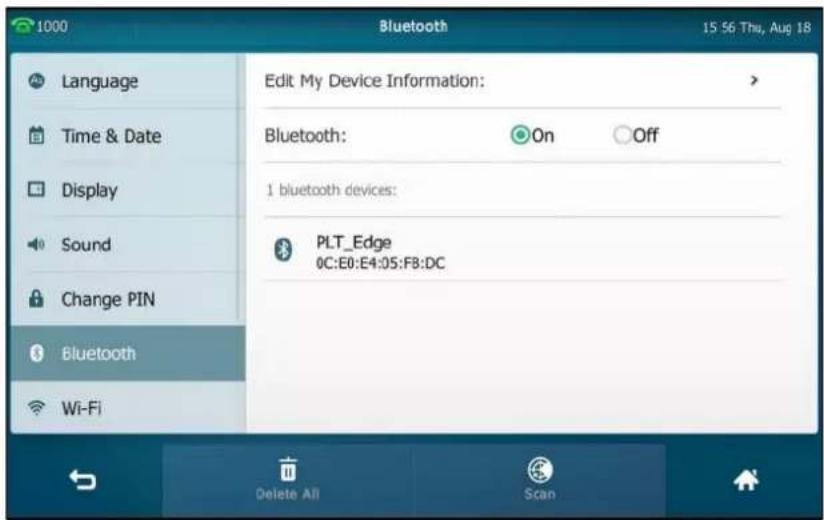
-
Tap the found Bluetooth device to connect the Bluetooth headset to your phone.
-
Enter the PIN in the prompted PIN field.
The default PIN is "0000".
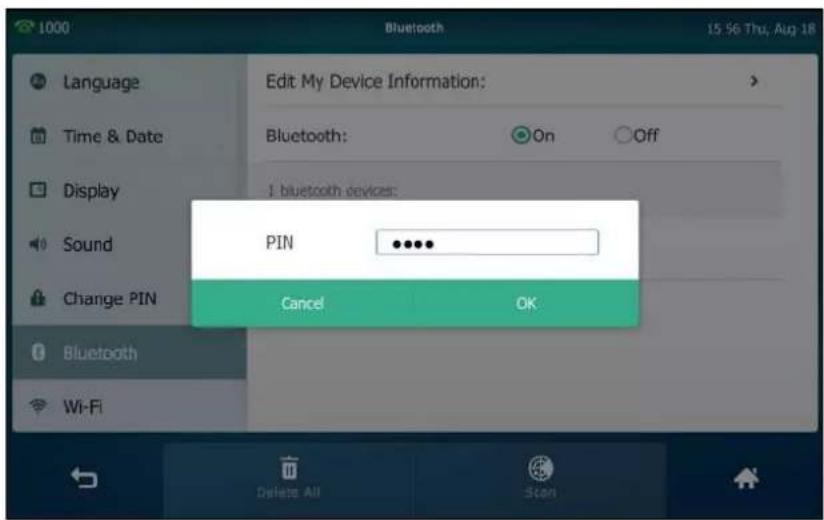
- Tap OK.
The touch screen displays "Connect Success.".
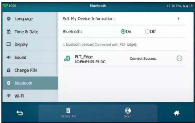
The Bluetooth icon 📋 appears on the status bar of the touch screen.

With the Bluetooth headset paired and connected, you can use the Bluetooth headset to place and answer calls. For more information, refer to the documentation from the Bluetooth headset manufacturer.
Editing Device Information
To edit device information via phone user interface:
- Tap ->Basic->Bluetooth->Edit My Device Information.
The touch screen displays the device name and MAC address. The MAC address cannot be edited.
- Enter the desired name in the Device Name field.
The default device name is SIP VP-T49G.

- Tap the Save soft key to accept the change or ↩ to cancel.
The pre-configured Bluetooth device name will display in scanning list of other device.
Disconnecting the Bluetooth Headset
To disconnect your Bluetooth headset from your phone:
-
Tap -> Basic->Bluetooth.
-
Tap the connected Bluetooth headset.

The Bluetooth headset is disconnected. To connect it to your phone again, tap the Bluetooth headset again.
Deleting the Paired Bluetooth Headset
You can delete your Bluetooth headset from your phone. When you delete the Bluetooth headset, it disappears from the bluetooth devices list. To connect it to your phone again, you need to scan it first, and then connect it again.
To delete paired Bluetooth headset via phone user interface:
1. Tap ->Basic->Bluetooth.
The touch screen displays the paired and connected Bluetooth headset.
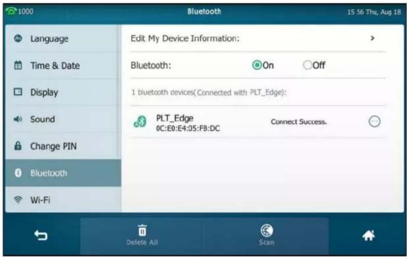
-
Tap ⬆ after the desired Bluetooth headset name.
-
Tap Delete in the pop-up dialog box.
The touch screen prompts the following warning "Delete selected item?".

- Tap OK to confirm the deletion or Cancel to cancel.
You can also delete all headsets by tapping the Delete All soft key.
Note
The icon ⋯ only appears after the device name of the Bluetooth device that you are connecting or have connected.
If you cannot connect a Bluetooth headset to the phone successfully, we recommend that you delete the Bluetooth headset in the bluetooth devices list (if it exists) before pairing it.
Deactivating the Bluetooth Mode
To deactivate the Bluetooth mode via phone user interface:
-
Tap ->Basic->Bluetooth.
-
Tap the Off radio box in the Bluetooth field.

The Bluetooth icon disappears from the touch screen.
Bluetooth mode is configurable via web user interface at the path Features->Bluetooth.
Bluetooth-Enabled Mobile Phone
Yealink SIP VP-T49G IP phone supports the use of your IP phone in conjunction with Bluetooth-enabled mobile phone. You can do the following:
Pair and connect your IP phone with a Bluetooth-enabled mobile phone to make and receive mobile calls. Your mobile phone is automatically assigned a line key on your IP phone.
- Import your mobile contacts into the IP phone.
- Use your IP phone as a hands free device for your mobile phone.
For operating instructions on activating/deactivating the Bluetooth mode, editing device information and disconnecting/deleting the paired Bluetooth-enabled mobile phone, refer to the operating instructions of Bluetooth Headset on page 123.
Note
Not all mobile phones support this function. Contact your system administrator for more information.
Pairing and Connecting the Bluetooth-Enabled Mobile Phone
You can only connect one Bluetooth device at a time. After connection, the IP phone will automatically find an available line key and assign the line key for Mobile Account. The Mobile
Account key's default label is "My Mobile". If there is no available line key, you may assign it manually.
The mobile phone will disconnect from your phone in the following introduced scenarios:
- Deactivate the Bluetooth mode from the IP phone.
- Connect a Bluetooth headset to the IP phone.
- Deactivate the Bluetooth mode from mobile phone.
• The distance between mobile phone and IP phone is more than 10 meters.
Before you pair a Bluetooth-Enabled mobile phone, check the Bluetooth mode on the Bluetooth-Enabled mobile phone to make sure that the Bluetooth-Enabled mobile phone is discoverable.
To pair and connect the Bluetooth-Enabled Mobile Phone with your phone:
-
Tap ->Basic->Bluetooth.
-
Tap the On radio box in the Bluetooth field.
If there is no Bluetooth-Enabled mobile phone found on the touch screen, tap the Scan soft key to search for the Bluetooth-Enabled mobile phone.
- Tap the desired Bluetooth-Enabled mobile phone in the Bluetooth devices list to connect the mobile phone to your phone.

4. Tap OK on both mobile phone and IP phone.

Then the IP phone will prompt "Would you like to sync phone contacts temporarily?".
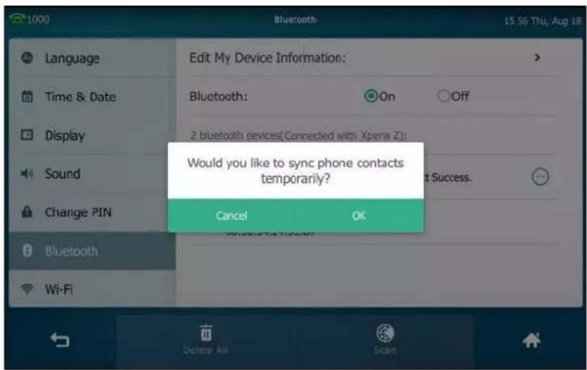
- (Optional.) Tap OK to enable the mobile contacts sync feature and the IP phone will sync the mobile contacts temporarily, or tap Cancel to disable mobile contacts sync feature and the IP phone will not sync the mobile contacts. If you tap Cancel, you can also manually enable the mobile contacts sync feature on the IP phone. For more information, refer to Syncing the Mobile Contacts to the IP Phone on page 133.
If you enable mobile contacts sync feature, you also need to authorize the IP phone to sync the contacts temporarily on the mobile phone.
The touch screen displays "Connect Success.".

The Bluetooth icon 📄 will display on the status bar of the touch screen.
And the IP phone automatically assigns a Mobile Account key.

For more information on how to configure the Mobile Account key, refer to Mobile Account on page 146. Before you configure the Mobile Account key, make sure the Bluetooth-Enabled mobile phone is connected. Otherwise the IP phone will prompt "Mobile Account is not connected!". If the distance between mobile phone and IP phone is out of the range of 10 meters or the Bluetooth mode on the mobile phone is deactivated, you can tap the Mobile Account key to reconnect the last paired Bluetooth-Enabled mobile phone.
Syncing the Mobile Contacts to the IP Phone
If you disable the mobile contacts sync feature when you pair and connect the Bluetooth-Enabled mobile phone to the IP phone (refer to Pairing and Connecting the Bluetooth-Enabled Mobile Phone), you need to enable the mobile contacts sync feature manually when you want to sync the mobile contacts the IP phone.
Note
Not all mobile phones support syncing the mobile contacts to IP phone. For more information, contact your system administrator.
To enable the mobile contacts sync feature manually:
- Tap -> Basic->Bluetooth.
- Tap ⬙ after the desired Bluetooth-Enabled mobile phone name.
- Tap the On radio box in the Mobile Contacts Sync field.

You need to authorize the IP phone to sync the contacts temporarily on the mobile phone.
And then the mobile contacts directory will appear in the IP phone directory list.
To view your mobile contacts on the IP phone:
- Tap ->Mobile Contacts.
The contacts in the mobile phone will display in the Mobile Contacts list.
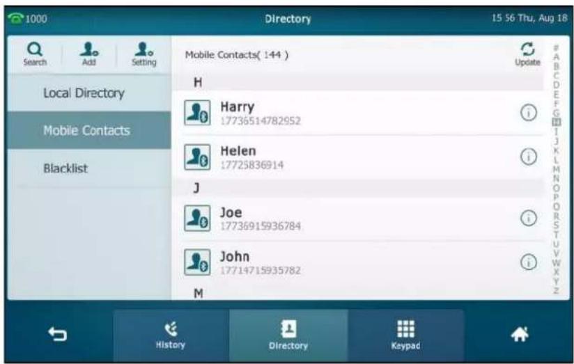
For operating instructions on adding contact to local/blacklist directory from mobile contacts directory, update the mobile contacts directory or placing calls to and searching for contacts in the mobile contacts directory, refer to the operating instructions of Mobile Contacts on page 111.
Note
If the mobile phone disconnects from the IP phone while the IP phone is loading the mobile contacts, the touch screen will prompt "Fail to download mobile contacts!", and the mobile contacts directory will not appear at the IP phone directory list.
Making a Mobile Phone Call by Using the IP Phone
When you make a mobile phone call by using your IP phone, the IP phone acts as a hands free device for your mobile phone. The call is made through your mobile phone, but the audio is present on and the call control is done by using the IP phone. You can have both mobile phone call and IP phone call on your IP phone, and two types of calls will not affect each other.
To make a call through a mobile phone:
1. Tap the My Mobile line key.

- Enter the desired number.
3. Tap Send by Mobile.

The outgoing call information will appear on both your IP phone and mobile phone screen. After the call is picked up, the audio goes through the IP phone, although the mobile phone screen also shows a connected call. You can hold, mute or end the call on the IP phone, and after you hold the call you can resume the call or place a new call.
Note
You can control the call's audio to go through the mobile phone or IP phone on your mobile phone. For example, if you choose Bluetooth, the audio will go through the IP phone; if you choose Handset earpiece or Speaker, the audio will go through the mobile phone.
The phone will first match the contacts in the mobile contacts directory to present the caller/callee identity when receiving/placing a mobile phone call.
Receiving Mobile Phone Calls by Using the IP Phone
If your mobile phone is paired and connected with the IP phone, an incoming call to your mobile phone is also shown on the IP phone.
To handle a mobile phone call by using the IP phone, do one of the following:
- Press 📄, tap the Answer soft key or pick up the handset to connect to the call.
- Tap the Reject soft key to reject the call.
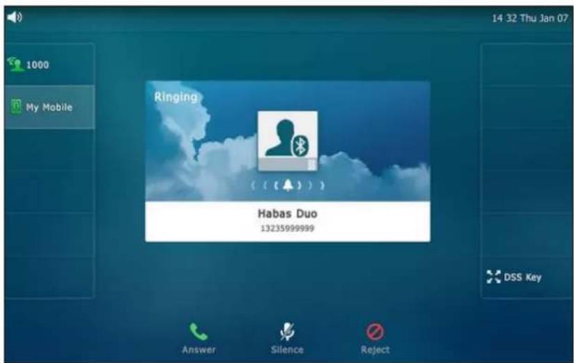
DSS Keys
There are two types of DSS keys: Line Keys and Programmable Keys. Details will be introduced in the following. The SIP VP-T49G IP phone supports 29 line keys and 7 programmable keys.
Line Keys
You can assign predefined functionalities to line keys. You can also define a label for a line key feature which will appear on the touch screen. Line keys allow you to quickly access features such as recall and voice mail. The line key can indicate the monitored status when the line keys are assigned with particular features, such as BLF. The default key type of line key 1-16 is Line. The default key type of line key 17-29 is N/A, which indicates that this line key provides no functionality until configuration.
You can also tap and hold the line keys on the idle screen to enter the line key configuration screen directly.
To assign functionality to a line key via phone user interface:
-
Tap ->Features->DSS Keys.
-
Tap the desired line key.
-
Select the desired key type from the Type field.
-
(Optional.) Select the desired key event type from the Key Type field.
-
(Optional.) Select the desired line from the Account ID field.
-
(Optional.) Enter the string that will appear on the touch screen in the Label field.
-
(Optional.) Enter the corresponding value in the Value field.
-
(Optional.) Enter the corresponding value in the Extension field.
This option is only applicable to BLF feature. For more information, refer to Busy Lamp Field (BLF) on page 229.
- Tap the Save soft key to accept the change or ↩ to cancel.
You can also tap DSS Key on the idle screen to enter the line key configuration screen directly.
Label Length
You can specify labels for some key features, which will be displayed on the idle touch screen. If the length of the label exceeds the maximum display length, the phone only displays the first few characters. You can configure the phone to display more characters via label length feature.
The following figure shows an example of label display when the label length feature is set to Extended:

The following figure shows an example of label display when the label length feature is set to Default:
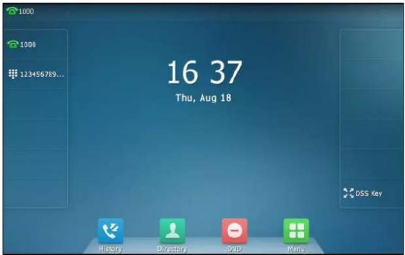
To configure the label length via web user interface:
- Click on DSSKey->Line Key.
- Select Extended from the pull-down list of Label Length.
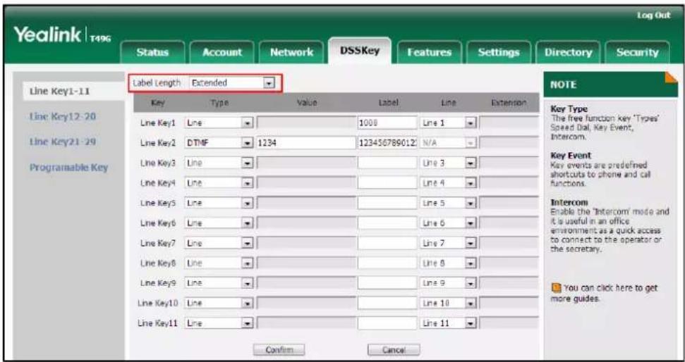
- Click Confirm to accept the change.
Note
Label length feature is configurable via web user interface only.
Line Key Features
Line key features are explained in the following subchapters in detail:
- Line
-
Speed Dial
-
Voice Mail
- Direct Pickup
- Group Pickup
• DTMF - Prefix
- Local Group
- XML Group
- XML Browser
- LDAP
- SMS
- Conference
- Forward
- Transfer
- Hold
• DND - Group Listening
- Zero Touch
- URL
- Phone Lock
- Directory
- Mobile Account
For the features not listed above, refer to Basic Phone Features on page 161 and Advanced Phone Features on page 229. For more information, contact your system administrator.
Line
You can use this key feature to accept incoming calls, place active calls on hold or resume a held call.
Dependencies: Type (Line)
Account ID (the account this feature will be applied to or GK account for H.323)
Label (key label displayed on the touch screen)
Usage: When the phone receives an incoming call,
- Tap the line key to accept the incoming call.
- Tap the line key to place a new call and the active call is placed on hold.
- Tap the line key again to resume the held call.
Speed Dial
You can use this key feature to speed up dialing the numbers frequently used or hard to remember.
Dependencies: Type (Speed Dial)
Account ID (the account this feature will be applied to)
Label (key label displayed on the touch screen)
Value (the number you want to dial out)
Usage: Tap the speed dial key to dial out the number specified in the Value field, using the account selected from the Account ID field.
Voice Mail
You can use this key feature to quickly connect voice mail. For more information, refer to Video/Voice Mail on page 281.
Dependencies: Type (Key Event)
Key Type (Voice Mail)
Account ID (the account this feature will be applied to)
Label (key label displayed on the touch screen)
Value (the voice mail access code)
Usage: Tap the voice mail key to dial out the voice mail access code. Then follow the voice prompt to listen to the voice mails.
Direct Pickup
You can use this key feature to answer someone else's incoming call on the phone.
Dependencies: Type (Key Event)
Key Type (DPickup)
Account ID (the account this feature will be applied to)
Label (key label displayed on the touch screen)
Value (the directed call pickup code followed by the target phone number)
Usage: Tap the direct pickup key on your phone when the target phone number receives an incoming call. The call is then answered on your phone.
Group Pickup
You can use this key feature to answer incoming calls in a group that is associated with their own group.
Dependencies: Type (Key Event)
Key Type (GPickup)
Account ID (the account this feature will be applied to)
Label (key label displayed on the touch screen)
Value (the group pickup code)
Usage: Tap the group pickup key on your phone when a phone number in the group receives an incoming call. The call is answered on your phone.
DTMF
You can use this key feature to send the specification of arbitrary key sequences via DTMF.
Dependencies: Type (Key Event)
Key Type (DTMF)
Label (key label displayed on the touch screen)
Value (DTMF sequence)
Note
DTMF sequence can only contain "0-9", "*", "#" and "A-D".
Usage: Tap the DTMF key during an active call to send the key sequence specified in the Value field.
Prefix
You can use this key feature to add a specified prefix number before the dialing number.
Dependencies: Type (Key Event)
Key Type (Prefix)
Label (key label displayed on the touch screen)
Value (the prefix number)
Usage: Tap the prefix key when the phone is idle, the phone will then enter the dialing screen and display the prefix number that you specified in the Value field. You can enter the remaining digits and then dial out.
Local Group
You can use this key feature to quickly access a contact group in the local directory. For more information, refer to Local Directory on page 89.
Dependencies: Type (Key Event)
Key Type (Local Group)
Local Group (the contact group name you want to access)
Label (key label displayed on the touch screen)
Usage: Tap the local group key to access the contact group specified in the Local Group field.
XML Group
You can use this key feature to quickly access a remote group in your remote phone book. You should configure a remote phone book in advance. For more information, refer to Remote Phone Book on page 107.
Dependencies: Type (Key Event)
Key Type (XML Group)
XML Group (the remote group name you want to access if the remote phone book is configured)
Label (key label displayed on the touch screen)
Usage: Tap the XML group key to access the remote group specified in the XML Group field.
XML Browser
You can use this key feature to quickly access an XML browser. The XML browser allows you to create custom services which meet your functional requirements on the server. You can customize practical applications, such as weather report, stock information, Google search, etc.
Dependencies: Type (Key Event)
Key Type (XML Browser)
Label (key label displayed on the touch screen)
Value (the access URL for XML browser)
Usage: Tap the XML browser key to access the XML browser specified in the Value field.
LDAP
You can use this key feature to quickly access a LDAP search screen.
Dependencies: Type (Key Event)
Key Type (LDAP)
Label (key label displayed on the touch screen)
Usage:
-
Tap the LDAP key to access the LDAP search screen.
-
Enter a few continuous characters of the contact name or continuous numbers of the contact number.
The contacts whose name or phone number matches the characters entered will appear on the touch screen.
SMS
You can use this key feature to quickly access text message. For more information, refer to Short Message Service (SMS) on page 277.
Dependencies: Type (Key Event)
Key Type (SMS)
Label (key label displayed on the touch screen)
Usage: Tap the DSS key when the phone is idle to access text message.
Conference
You can use this key feature to set up a conference call. For more information, refer to Conference on page 212.
Dependencies: Type (Key Event)
Key Type (Conference)
Label (key label displayed on the touch screen)
Value (the number added to the conference)
Usage: Tap the conference key during an active call to set up a conference with the number specified in the Value field.
Note
If the Value field is left blank, the conference key performs the same function as Conference soft key during a call.
Forward
You can use this key feature to forward an incoming call to someone else. For more information, refer to Call Forward on page 198.
Dependencies: Type (Key Event)
Key Type (FWD)
Label (key label displayed on the touch screen)
Value (the number you want to forward to)
Usage: Tap the forward key to forward an incoming call to the number specified in the Value field.
Note
If the Value field is left blank, the forward key performs the same function as the FWD soft key when receiving an incoming call.
Transfer
When there is an active call on the phone, you can use this key feature to handle the call differently depending on the transfer mode assigned to the DSS key.
Dependencies: Type (Key Event)
Key Type (Transfer)
Label (key label displayed on the touch screen)
Value (the number you want to transfer to)
Usage:
- When the transfer mode via dsskey is Blind Transfer, tap the transfer key to complete the blind transfer to the number specified in the Value field.
- When the transfer mode via dsskey is Attended Transfer, tap the transfer key to dial out the number specified in the Value field, and then perform the attended or semi-attended transfer.
- When the transfer mode via dsskey is New Call, tap the transfer key to place a new call to the number specified in the Value field.
Note
Transfer mode via dsskey is configurable via web user interface at the path Features->Transfer->Transfer Mode via Dsskey.
If the Value field is left blank, the transfer key performs the same function as the TRANSFER key or the Transfer soft key during a call. For more information, refer to Call Transfer on page 208.
Hold
You can use this key feature to place an active call on hold or retrieve a held call.
Dependencies: Type (Key Event)
Key Type (Hold)
Label (key label displayed on the touch screen)
Usage:
- Tap the hold key during an active call to place the call on hold.
- Tap the hold key again to retrieve the held call.
DND
You can use this key feature to enable or disable DND. You can also use this key feature to access the custom DND screen. For more information, refer to Do Not Disturb (DND) on page 193.
Dependencies: Type (Key Event)
Key Type (DND)
Label (key label displayed on the touch screen)
Usage:
When DND is in phone mode:
- Tap the DND key to enable DND.
-
Tap the DND key again to disable DND.
When DND is in custom mode: -
Tap the DND key to access the custom DND screen. You can enable or disable DND for one or all accounts.
Group Listening
You can use this key feature to activate the Speakerphone and Handset/Headset mode at the same time. It is suitable for group conversations which have more than one person at one side. You are able to speak and listen through the handset/headset, while the others nearby can only listen through the speaker.
Dependencies: Type (Key Event)
Key Type (Group Listening)
Label (key label displayed on the touch screen)
Usage:
- During a call, tap the group listening key to activate the group listening mode.
- You can then speak and listen through the handset/headset, while other people at your side can only listen through the speaker at the same time.
- Tap the group listening key again to deactivate the group listening mode.
Zero Touch
You can use this key feature to quickly configure auto provision and network parameters.
Dependencies: Type (Key Event)
Key Type (Zero Touch)
Label (key label displayed on the touch screen)
Usage:
- Tap the zero touch key to access the zero touch screen.
- Tap the OK soft key within a few seconds.
- Configure the network parameters in the corresponding fields.
- Tap the Next soft key.
- Configure the auto provision parameters in the corresponding fields.
- Tap the Next soft key.
The phone will reboot to update configurations.
URL
You can use this key feature to trigger the phone to send an HTTP GET request containing a specific URL.
Dependencies: Type (URL)
Label (key label displayed on the touch screen)
URL (the URL contained in the HTTP GET request)
Usage: Tap the URL key to trigger the phone to send an HTTP GET request containing the URL specified in the URL field.
Phone Lock
You can use this key feature to immediately lock your phone instead of long pressing #_END. For more information, refer to Phone Lock on page 81.
Dependencies: Type (Key Event)
Key Type (Phone Lock)
Label (key label displayed on the touch screen)
Usage: Tap the phone lock key to immediately lock your phone instead of long pressing #REND.
Directory
You can use this key feature to easily access frequently used lists. For more information, refer to Local Directory on page 89.
Dependencies: Type (Key Event)
Key Type (Directory)
Label (key label displayed on the touch screen)
Usage: Tap the directory key to immediately access frequently used lists.
Note
The directory key performs the same function as the Directory key when the phone is idle.
Mobile Account
You can use this key feature to accept incoming mobile calls, place active mobile calls on hold on your IP phone. For more information, refer to Bluetooth-Enabled Mobile Phone on page 129.
Dependencies: Type (Mobile Account)
Label (key label displayed on the touch screen)
Usage: When the IP phone receives an incoming mobile call,
- Tap the mobile account key to accept the incoming call.
- Tap the mobile account key to place a new call and the active call is placed on hold.
Programable Key
You can customize the soft keys and function keys.
To customize programable key via web user interface:
- Click on DSSKey->Programable Key.
- Customize specific features for these keys.

- (Optional.) Enter the string that will appear on the touch screen in the Label field.
Label is configurable only when customizing SoftKey (1-4).
- Click Confirm to accept the change.
You can click Reset to default to reset custom settings to defaults.
Then you can press the keys on the phone to perform the features you configured.
For example:
Switch Account Up
You can press Switch Account Up key to change the default account.
Dependencies: Type (Switch Account Up)
Usage: Press the Switch Account Up key to scroll up the account list to select the desired default account.
Switch Account Down
You can press Switch Account Down key to change the default account.
Dependencies: Type (Switch Account Down)
Usage: Press the Switch Account Down key to scroll down the account list to select the desired default account.
Note
You can only configure the SoftKey (1-4) as the prefix key.
Programable keys are configurable via web user interface only.
Account Management
You can register one or multiple accounts on the SIP VP-T49G IP phone. You can also configure each line key to associate with an account or configure multiple line keys to associate with an account.
Account Registration
To register an account via phone user interface:
- Tap ->Advanced (default password: admin) ->Account.
- Tap the desired account.
- Tap the Activation field.
- Tap Enabled in the pop-up dialog box.
5. Enter the desired value in the Label, Display Name, Register Name, User Name,
Password and SIP Server1/2 field respectively. Contact your system administrator for more information.
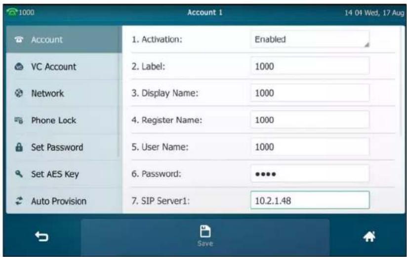
- If you use the outbound proxy servers, do the following:
1) Tap the Outbound Status field.
2) Tap Enabled in the pop-up dialog box.
3) Enter the desired value in the Outbound Proxy1/2 field respectively. Contact your system administrator for more information.
- Tap the Save soft key to accept the change or ↩ to cancel.
You can repeat steps 2 to 7 to register more accounts.
The following figures demonstrate single or multiple accounts registered on the phone:
Single account:
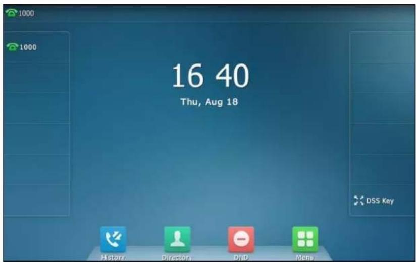
Multiple accounts:

To disable an account via phone user interface:
- Tap ->Advanced (default password: admin) ->Account.
- Tap the desired account.
- Tap the Activation field.
- Tap Disabled in the pop-up dialog box.
- Tap the Save soft key to accept the change or ↩ to cancel.
Account registration is configurable via web user interface at the path Account->Register.
Default Account
To configure the default account via phone user interface:
- Tap ->Features->Default Account.
- Tap the Default Account field.
- Tap the desired account in the pop-up dialog box.

4. Tap the Save soft key to accept the change or ↩ to cancel.
The label of the default account is displayed on the left of the status bar. The IP phone will use this account by default when dialing out.
You can also tap the label of the default account, and then tap the desired account to be the new default account.

Multiple Line Keys per Account
You can configure multiple line keys to associate with an account. This enhances call visualization and simplifies call handling.
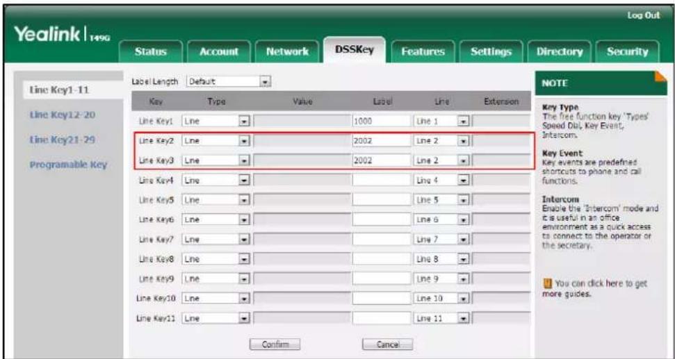
If this is the case, the touch screen will resemble the following figure:
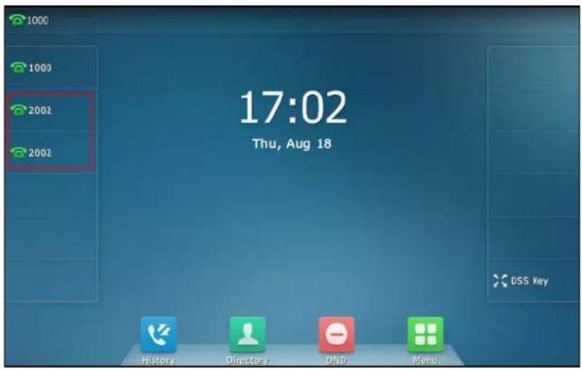
Incoming calls to this account will be distributed evenly among the available line keys. Outgoing calls will be distributed similarly.
Your phone can be configured to have a combination of accounts with a single line key and accounts with multiple line keys.
Dial Plan
Dial plan is a string of characters that governs the way your SIP VP-T49G IP phone processes the inputs received from your phone keypad. The SIP VP-T49G IP phone supports the following dial plan features:
- Replace Rule
- Dial-now
- Area Code
- Block Out
Basic expression syntaxes you need to know:
| . | The dot "." can be used as a placeholder or multiple placeholders for any character. Example: "12." would match "123", "1234", "12345", "12abc", etc. |
| x | An "x" can be used as a placeholder for any character. Example: "12x" would match "121", "122", "123", "12a", etc. |
| - | Numeric ranges are allowed within the brackets: Digit "-" Digit. Example: "[5-7]" would match the number"5", "6"or "7". |
| [] | The square brackets "[]" can be used as a placeholder for a single character which matches any of a set of characters. Example: "91[5-7]1234" would match "9151234", "9161234", "9171234". |
| () | The parentheses "()” can be used to group together patterns, for instance, to logically combine two or more patterns. Example: "([1-9])([2-7])3" would match "923", "153", "773", etc. |
| The "" should be followed by the sequence number of a parenthesis. The "" plus the sequence number means the whole character or characters placed in the parenthesis. The number directs to the right parenthesis when there are more than one. Example:A replace rule configuration, Prefix: "001(xxx)45(xx)", Replace: "90011452". When you dial out "0012354599" on your phone, the IP phone will replace the number with "90012354599". "1" means 3 digits in the first parenthesis, that is, "235". "$2" means 2 digits in the second parenthesis, that is, "99". |
Note
Dial plan is configurable via web user interface only.
Replace Rule
You can configure one or more replace rules (up to 100) to remove the specified string and replace it with another string. You can configure a pattern with wildcards (refer to the expression syntax in the table above), so that any string that matches the pattern will be replaced. This feature is convenient for you to dial out a long number. For example, a replace rule is configured as "Prefix: 1" and "Replace: 1234", when you try to dial out the number "1234", you just need to enter "1" on the phone and then tap Send.
To add a replace rule via web user interface:
- Click on Settings->Dial Plan->Replace Rule.
- Enter the string (e.g., 1) in the Prefix field.
- Enter the string (e.g., 1234) in the Replace field.
- Enter the desired line ID in the Account field or leave it blank.

- Click Add to add the replace rule.
When you enter the number "1" using the keypad or the onscreen keyboard and then tap Send, the phone will dial out "1234" instead.
Note
The valid values for the Account field can be one or more digits among 1-16. Every two digits must be separated by a comma. For example, when you enter the value "1, 2" in the Account field, this replace rule will apply to account1 and account2.
If you leave the Account field blank or enter 0, the replace rule will apply to all accounts.
To edit a replace rule via web user interface:
- Click on Settings->Dial Plan->Replace Rule.
- Select the desired replace rule by checking the checkbox.
- Edit the values in the Prefix and Replace fields.
- Enter the desired line ID in the Account field or leave it blank.
- Click Edit to accept the change.
To delete one or more replace rules via web user interface:
- Click on Settings->Dial Plan->Replace Rule.
- Select one or more replace rules by checking the checkbox(es).
- Click Del to delete the replace rule(s).
Dial-now
You can configure one or more dial-now rules (up to 100) on your phone. When the dialed number matches the dial-now string, the number will be dialed out automatically. For example, a dial-now rule is configured as "2xx", any entered three-digit string beginning with 2 will then be dialed out automatically on the phone.
To add a dial-now rule via web user interface:
- Click on Settings->Dial Plan->Dial-now.
- Enter the desired value (e.g., 2xx) in the Rule field.
- Enter the desired line ID in the Account field or leave it blank.
For more information on the valid values for the Account field, refer to Replace Rule on page 152.

- Click Add to add the dial-now rule.
When you enter the number "234" using the keypad or the onscreen keyboard, the phone will dial out "234" automatically without the pressing of any key.
Note
You can also edit or delete the dial-now rule. For more information, refer to Replace Rule on page 152.
Delay Time for Dial-Now Rule
You can configure the delay time for dial-now rules. That is, you can configure your phone to automatically dial out the phone number which matches a dial-now rule, after the designated delay time.
To configure the delay time for dial-now rule via web user interface:
-
Click on Features->General Information.
-
Enter the time between 0 and 14 (seconds) in the Time-Out for Dial-Now Rule field. The default value is "1".
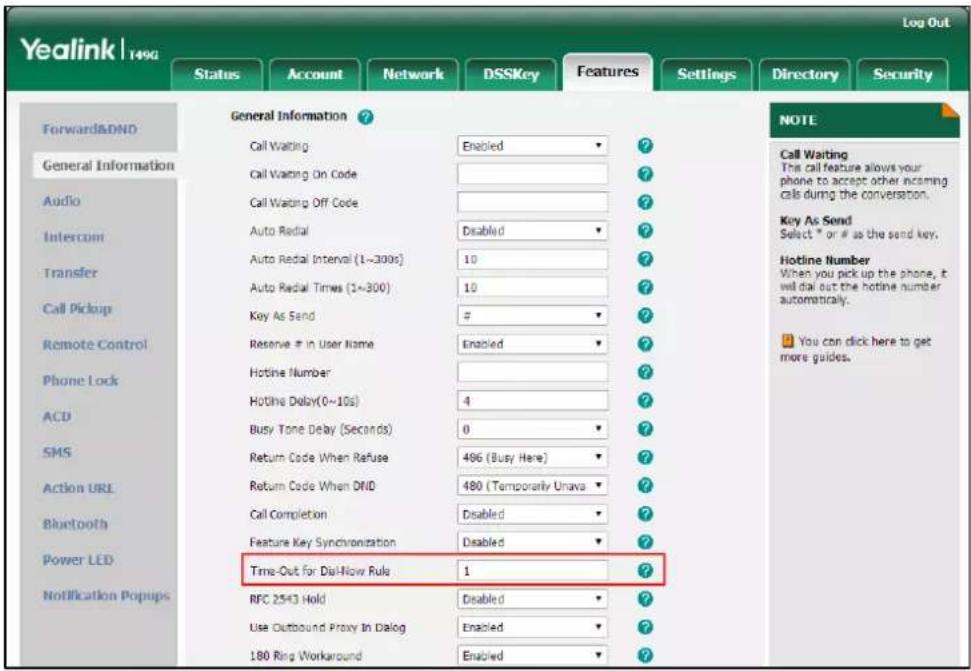
- Click Confirm to accept the change.
Note
Delay time for dial-now rule is configurable via web user interface only.
Area Code
Area codes are also known as Numbering Plan Areas (NPAs). They usually indicate geographical areas in a country. This feature is necessary when dialing a phone number outside the code area. For example, an area code is configured as "Code: 0592, Min Length: 1, Max Length: 15". When you dial out the number "56789" (the length of the number is between 1 and 15), the phone will add the area code and dial out the number "059256789". You can only configure one area code rule on your phone.
To configure the area code and lengths via web user interface:
- Click on Settings->Dial Plan->Area Code.
- Enter the desired values in the Code, Min Length (1-15) and Max Length (1-15) fields.
3. Enter the desired line ID in the Account field or leave it blank.
For more information on the valid values for the Account field, refer to Replace Rule on page 152.

4. Click Confirm to accept the change.
Note
The default value of minimum and maximum length is 1 and 15 respectively.
Block Out
You can block some specific numbers (up to 10) from being dialed on your phone. When you dial a block out number on your phone, the dialing will fail and the touch screen will prompt "Forbidden Number".
To add a block out number via web user interface:
- Click on Settings->Dial Plan->Block Out.
- Enter the desired value in the BlockOut Number field.
- Enter the desired line ID in the Account field or leave it blank.
For more information on the valid values for the Account field, refer to Replace Rule on page 152.

- Click Confirm to add the block out number.
Emergency Number
Public telephone networks in countries around the world have a single emergency telephone number (emergency services number), that allows a caller to contact local emergency services for assistance when necessary. The emergency telephone number may differ from country to country. It is typically a three-digit number so that it can be easily remembered and dialed quickly. Some countries have a different emergency number for each of the different emergency services.
You can specify the emergency telephone numbers on the IP phone for contacting the emergency services in an emergency situation. You can dial these numbers when the phone is locked. For more information on phone lock refer to Phone Lock on page 81.
Note
Contact your local phone service provider for available emergency numbers in your area.
To specify emergency numbers via web user interface:
- Click on Features->Phone Lock.
- Enter the emergency number in the Emergency field.
For multiple emergency numbers, enter a comma between every two numbers. The default emergency numbers are 112, 911 and 110.
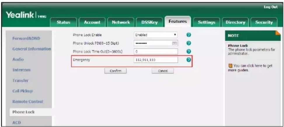
- Click Confirm to accept the change.
Note
Emergency number is configurable via web user interface only.
Live Dialpad
You can enable live dialpad on the SIP VP-T49G IP phone, which enables the IP phone to automatically dial out a phone number without the pressing of the send key. You can also
configure a delay, where the phone will dial out the phone number automatically after the designated period of time.
To enable the live dialpad via web user interface:
- Click on Settings->Preference.
- Select Enabled from the pull-down list of Live Dialpad.
- Enter the desired delay time in the Inter Digit Time(1\~14s) field.
The default delay time is 4.

4. Click Confirm to accept the change.
Note
Live dialpad is configurable via web user interface only.
Hotline
You can dial a hotline number immediately upon lifting the handset, pressing the Speakerphone key or tapping the line key. You can also configure a delay, where the phone will dial out the hotline number automatically after a designated period of time.
To configure the hotline number via phone user interface:
-
Tap ->Features->Hot Line.
-
Enter the desired number in the Number field.
3. Enter the desired delay time in the Hotline Delay 0-10(s) field.
The default value is "4".

4. Tap the Save soft key to accept the change or ↩ to cancel.
Hotline is configurable via web user interface at the path Features->General Information.
Basic Phone Features
The SIP VP-T49G IP phone is designed to be easily used like a regular phone on a public switched telephone network (PSTN). You can place calls, answer calls, transfer a call to someone else, or conduct a conference call.
This chapter provides basic operating instructions for the SIP VP-T49G IP phone. Topics include:
- Placing Calls
- Answering Calls
- Ending Calls
- Changing Video Call Settings
- External Monitor
- Redialing Numbers
- Recent Call In Dialing
- Auto Answer
- Auto Redial
- Call Completion
- Recall
- Call Mute
- Call Hold/Resume
- Do Not Disturb (DND)
- Call Forward
- Call Transfer
- Call Waiting
- Conference
- Call Park
- Call Pickup
- Anonymous Call
- Anonymous Call Rejection
• Capturing Screenshots during a Video Call
- Viewing the Pictures Stored in Your USB Flash Drive
Placing Calls
You can dial using the phone number/SIP URI/IP address/name (User Name for SIP account, H.323 Name for H.323 account). The maximum SIP URI length is 32 characters. For example, SIP URI: 3606@sip.com. For more information on IP call, refer to SIP IP Call on page 336. The following describes how to place a call using the phone number.
You can place a call in one of three ways using your SIP VP-T49G IP phone:
- Using the handset
- Using the speakerphone
- Using the headset
You can also dial the number first, and then choose the way you want to speak to the other party.
You can also dial an entry/contact from call history, local directory or remote phone book. For more information, refer to Contact Management on page 89 and Call History Management on page 113.
By default, you can set up a video call with the other party that is video-enabled. The IP phone can set up video calls with only two parties (even if more than two parties that set up a call with you can send video). To place an audio-only call, make sure the video feature is disabled. For more information, refer to Changing the Video Settings on page 173.
During a call, you can alternate between Speakerphone, Headset, and Handset modes by pressing the Speakerphone key, the HEADSET key, or by picking up the handset.
The call duration of the call and far-site's information (name or phone number) is visible on the touch screen. In the figure below, the video call to "Habas Duo" has lasted 7 seconds.

Note
The phone will enter the video call full-screen within 5 seconds during a call, you may tap or blank area at the top or bottom of the screen to see the soft keys.

In the figure below, the audio-only call to "Jerry" (the phone number: 1039) has lasted 6 seconds.

To place a call using the handset:
- Pick up the handset.
- Enter the desired number.
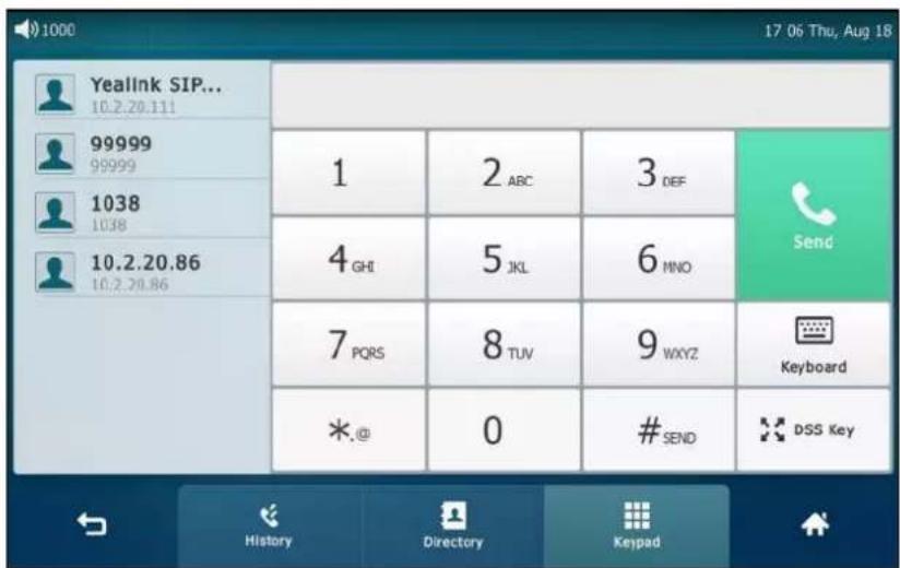
3. Press #send , or tap Send.
The # key is configured as a send key by default. You can also set the * key as the send key, or set neither. For more information, refer to the Key as Send on page 81.
You can also tap History or Directory to search for an entry or contact after picking up the handset, and then tap the desired entry or contact to place a call.
To place a call using the hands-free (speakerphone) mode:
Do one of the following:
- With the handset on-hook, press 📄 or tap the line key to obtain a dial tone. Enter the desired number.
Press #send or tap Send.
- With the handset on-hook, enter the desired number.
Press 📄, #send or tap Send.
To place a call using the headset:
Do one of the following:
- With the optional headset connected, press Ⓞ to activate the headset mode.
Tap the line key to obtain a dial tone.
Enter the desired number.
Press #send or tap Send.
- With the optional headset connected, press 🔒 to activate the headset mode.
Enter the desired number.
Press #send or tap Send.
Note
To permanently use the headset mode, refer to Headset Prior on page 122.
The SIP VP-T49G IP phone can handle multiple calls at a time. However, only one active call (the call that has audio associated with it) can be in progress at any time. The SIP VP-T49G IP phone can handle a maximum of 50 calls at one time.
To place multiple calls:
You can have more than one call on your SIP VP-T49G IP phone. To place a new call during an active call, do one of the following:
- Tap the line key. The active call is placed on hold.
Enter the desired number.
Press #send or tap Send.
- Press 📋 or tap the Hold soft key to place the original call on hold.
Tap the NewCall soft key.
Enter the desired number using the keypad or the dial pad.
Press #send or tap Send.
You can tap the desired call, and then tap the Resume soft key to retrieve it.
Note
If multiple accounts are registered on the phone, you can first tap the desired line key on the idle screen or tap the desired line from the status bar in dialing screen, and then you can use the selected account to place a call.
Answering Calls
When you are not in another call, you can answer a call in one of three ways:
• Using the handset
• Using the speakerphone
- Using the headset
Note
You can reject incoming calls by tapping the Reject soft key to stop the phone from playing ring tone. You can also activate the Do Not Disturb mode to reject the incoming calls without ringing on your phone. For more information, refer to Do Not Disturb (DND) on page 193.
You can forward incoming calls to someone else by tapping the FWD soft key. For more information, refer to Call Forward on page 198.
Answering When Not in Another Call
Call duration and destination will always appear on the touch screen for the active call.
To answer a call using the handset:
- Pick up the handset.
To answer a call using the hands-free (speakerphone) mode:
Do one of the following:
- Press
- With the handset on-hook and the headset mode deactivated, tap the Answer soft key.
- With the handset on-hook and the headset mode deactivated, tap the line key.
To answer a call using the headset:
Do one of the following:
- Press Ⓞ.
- With the headset mode activated, tap the Answer soft key.
- With the headset mode activated, tap the line key.
Answering When in Another Call
If you have an active call, and an incoming call arrives on the phone. The incoming call information is displayed on the touch screen.
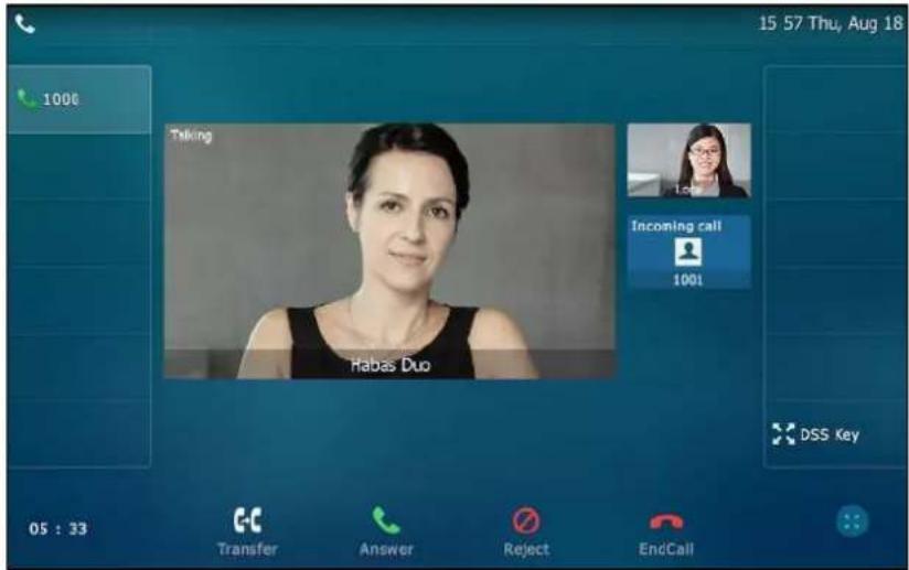
Do one of the following:
- Tap the Answer.
- Tap the incoming call avatar.
Tap the Answer.

The incoming call is answered and the original call is placed on hold.
Ending Calls
To end a call:
Do one of the following:
- If you are using the handset, tap the EndCall soft key or hang up the handset.
- If you are using the headset, tap the EndCall soft key.
- If you are using the speakerphone, press or tap the EndCall soft key.
Note
To end a call placed on hold, you can tap the EndCall soft key to end the call directly, or tap the Resume soft key to resume the call before ending it.
Changing Video Call Settings
When you update video settings, you can change the way for the current video call or all video calls to display on your IP phone.
You can update the following video settings on your phone:
- Stopping Transmitting Video during a Call
Changing the Clarity of Local-Site Video - Changing the Video Settings
- Changing the Video Layout during Calls
- Previewing the Local-Site Video
Stopping Transmitting Video during a Call
You can stop your phone from automatically transmitting your video during a video call.
However, you cannot turn off far-site video.
There are three ways to stop transmitting video during an active video call:
- Press

- Swipe down from the top of the screen in the video call screen (refer to Video Call Screen Display), and then tap Video.
- Turn off shutter switch.
If you stop transmitting video, the icon 📋 will display on the local-site video, as shown below:
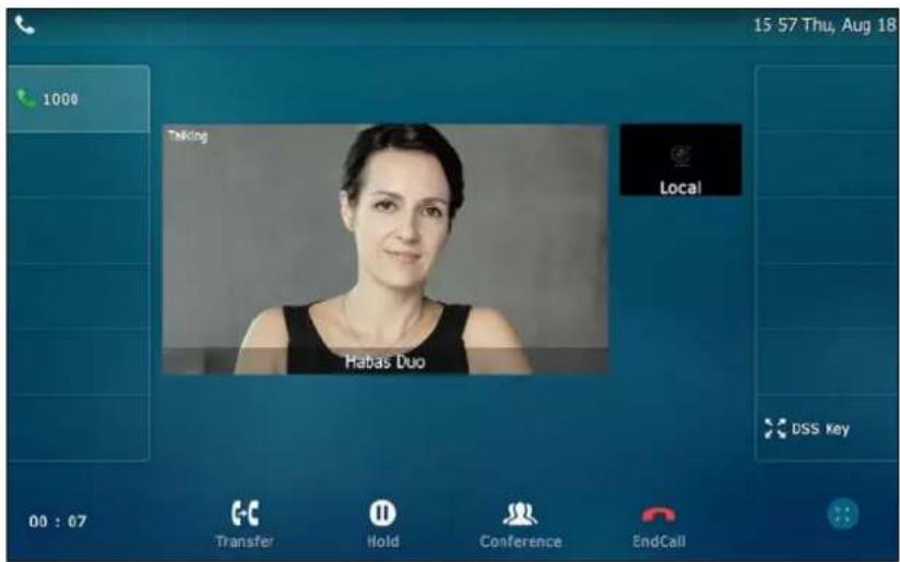
Your camera will not transmit video to your contact and the far site cannot see you.
Stopping transmitting video does not create an audio-only call. Even if you stop transmitting video, you can see the other party, and the call is still a video call. To place an audio-only call, contact your system administrator.
Changing the Clarity of Local-Site Video
You can change the clarity of your video, including the sharpness, brightness and contrast of your video stream before a video call. If your camera faces a bright light source, such as a bright window, you may need to increase the camera's sharpness, brightness and contrast levels so the other party can have a better video call experience with you.
Scene Mode
SIP VP-T49G IP phone provides four scene modes - standard mode, warm color mode, cool color mode and manual mode. You can select one of them to obtain a better video call experience if required. If you select manual mode, you may need to know how to set parameters of camera in advance (e.g., white balance, sharpness and brightness).
To configure scene mode via phone user interface:
-
Tap → Basic → Camera Setting.
-
Tap the Scene Mode field.
-
Tap the desired item in the pop-up dialog box.
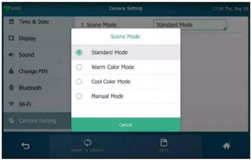
If you tap Manual Mode, you can do the following:
1) Tap the White Balance field.
2) Tap Auto or Manual Mode in the pop-up dialog box.
3) (Optional.) Enter the desired value in the Red Gain and Blue Gain field respectively. Red Gain and Blue Gain fields appear only if White Balance field is set to Manual Mode.
Red Gain - Sets how red your video displays. You can set a level between 0 (normal) and 100 (most). The default level is 0.
Blue Gain - Sets how blue your video displays. You can set a level between 0 (normal) and 100 (most). The default level is 0.
4) Enter the desired value in the Sharpness, Brightness, Contrast Setting and Saturation field respectively.

Sharpness - Sets the clarity of detail in your video. You can set a level between 0 (lowest) and 100 (highest). The default level is 50.
Brightness - Sets how brightly your video displays. You can set a level between 0 (dimmest) and 100 (brightest). The default level is 50.
Contrast Setting - Sets the difference in brightness between the light and dark areas of your video. You can set a level between 0 (no contrast increase) and 100 (highest). The default level is 0.
Saturation - Sets how much color your video displays. You can set a level between 0 (lowest) and 100 (highest). The default level is 100.
5) Tap the NR2D-level field.
NR2D-level - Sets the level to reduce the image noise. You can set to Off, Low, Middle and High. The default value is Middle.
6) Tap the desired item in the pop-up dialog box.
- Tap the Save soft key.
The touch screen will prompt "Save succeeded! Preview the video effect?".

- Tap OK to accept the change and preview the video or Cancel to go back to the menu screen.
Scene mode is configurable via web user interface at the path Settings->Camera.
You can also select scene mode when previewing the local-site video. For more information, refer to Previewing the Local-Site Video on page 178.
To reset manual settings via phone user interface:
- Tap ->Basic->Camera Setting.
2. Tap the Reset To Default soft key.

The touch screen prompts "Reset to default setting?".

3. Tap OK to accept the change or Cancel to cancel.
Reset Manual Settings is configurable via web user interface at the path Settings->Camera.
Exposure
Exposure compensation is used to compensate the camera effectively when shooting in a backlight environment. If the environment light is dark, increase the compensation value.
To configure exposure via web user interface:
- Click on Setting->Camera.
- Select the desired value from the pull-down list of Exposure Compensation, or select Off to turn off exposure compensation.
The value of exposure compensation ranges from 1 (lowest)-3 (highest), the default value is Off.

- Select the desired value from the pull-down list of Flicker.
Flicker - Adjusts the flickering of your video captured by the camera sensor. You can set to 50 Hz (flicker avoidance for Europe and Asia) or 60 Hz (flicker avoidance for North America). The default value is 50 Hz.

- Click Confirm to accept the change.
Note
Exposure can be configurable via web user interface only.
Changing the Video Settings
You can change the setting of your video via phone user interface or web user interface, including video enable, auto start video, auto answer video mute, uplink bandwidth and downlink bandwidth.
To configure the video settings via phone user interface:
-
Tap ->Basic->Video Setting.
-
Tap the Video Enable, Auto Start Video, Auto Answer Video Mute, Uplink Bandwidth or Downlink Bandwidth field respectively.
Video Enable - Enables or disables the IP phone to use camera during a call. You can set to Enabled or Disabled. The default value is Enabled. If you set to Disabled, the IP phone can only place/receive an audio-only call.
Auto Start Video – Enables or disables the IP phone to transmit local-site video at once for all incoming calls. You can set to Enabled or Disabled. The default value is Enabled.
Auto Answer Video Mute - Enables or disables the IP phone not to transmit the video when an incoming call is automatically answered. You can set to Enabled or Disabled. The default value is Disabled.
Uplink Bandwidth - Sets the maximum uplink bandwidth of video call. You can set to Auto, 4000kb/s, 3000kb/s, 2000kb/s, 1500kb/s, 1280kb/s, 1024kb/s, 768kb/s, 640kb/s, 512kb/s, 384kb/s or 256kb/s. The default value is Auto.
Downlink Bandwidth - Sets the maximum downlink bandwidth of video call. You can set to Auto, 4000kb/s, 3000kb/s, 2000kb/s, 1500kb/s, 1280kb/s, 1024kb/s, 768kb/s, 640kb/s, 512kb/s, 384kb/s or 256kb/s. The default value is Auto.
- Tap the desired value in the pop-up dialog box.

- Tap the Save soft key.
The touch screen will prompt "Save succeeded!".

Video setting is configurable via web user interface at the path Settings->Video.
Changing the Video Layout during Calls
During video calls, local-site and far-site video images are displayed on the touch screen. You can change the video layout.
The system supports three video layouts:
- One large, other small: One video image displays in a large size, the other video images along the right side of the screen displays in small sizes.
• Full screen: One video image displays in full size, the other video images are hidden. - Same size: All video images display in the same size.
To swap video during a video call via phone user interface:
- Tap the local-site (small window) video during a video call.

The local-site video will display in the center of the touch screen, and the far-site video will display on the top-right of the touch screen.
The following figure shows what the touch screen looks like after you tap the local-site video:

To change the video layout to the same size mode during a video call via phone user interface:
- From the video call full-screen, pinch close the large window.

The following figure shows what the touch screen looks like in the same size mode:
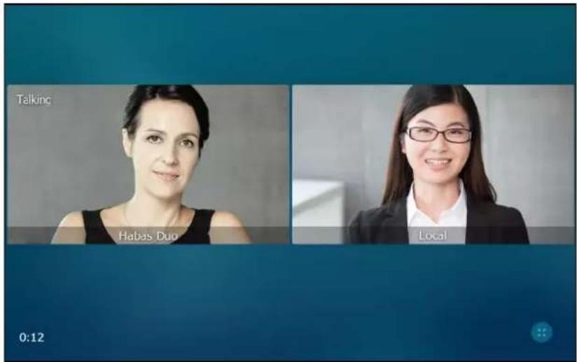
You can tap 📧 to go to video call screen (refer to Video Call Screen Display) or tap the desired image to go back to "one big, other small" layout.
To change the video layout to the full screen mode during a video call via phone user interface:
- From the video call full-screen, do one of the following:
- Tap the large window.
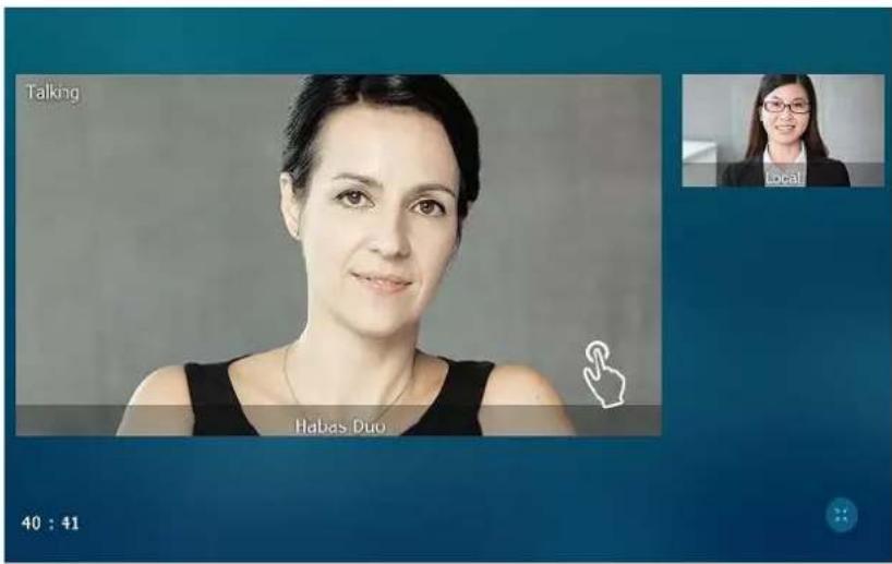
- Pinch open the large window.

The small window is hidden.
The following figure shows what the touch screen looks like in full screen mode:
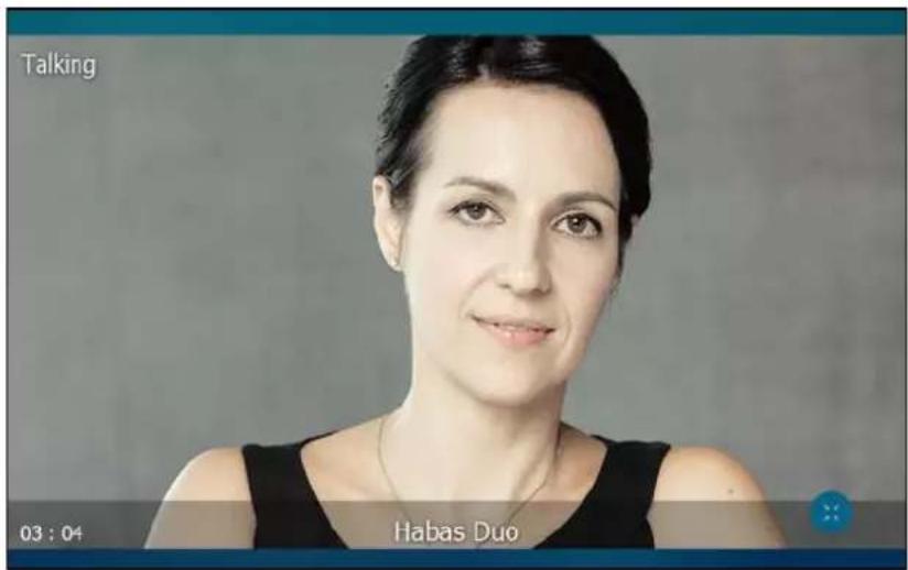
You can tap 📧 to go to video call screen (refer to Video Call Screen Display) or tap the video area to go back to "one big, other small" layout.
To change the video layout during a video conference call via phone user interface:
The default screen layout during a video conference call is the same size mode. The following figure shows what the touch screen looks like during a three-way video conference call:

You can tap 📧 to go to video call screen (refer to Video Call Screen Display) or tap one of the conference party to go back to the "one big, other small" layout.
The following figure shows what the touch screen looks like in the "one big, other small" layout during a three-way video conference call:
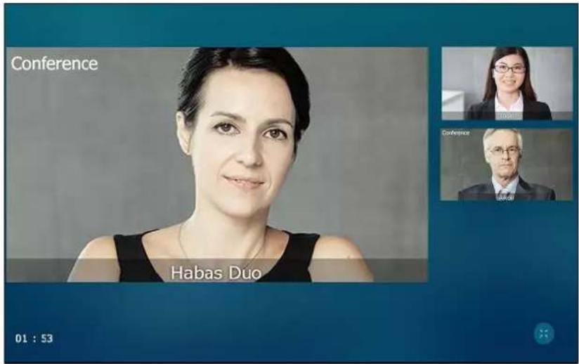
Previewing the Local-Site Video
You can preview the video of yourself that you display during video calls, and configure the scene mode at the same time.
To preview the local-site video when the phone is idle, do one of the following:
Press

Swipe down from the top of the screen to enter the control center and tap Video.
To configure the scene mode when previewing local-site video:
- Tap Standard Mode on the bottom-left of the screen.

- Tap the desired item in the pop-up dialog box.
If you select Manual Mode, the settings you have configured at the path

->Basic->Camera Setting->Scene Mode will be applied. For more information, refer to Scene Mode on page 168.
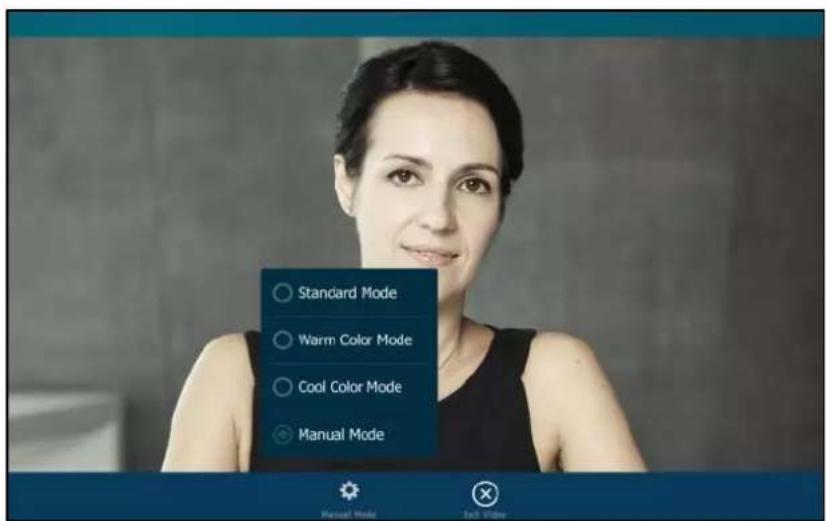
- Press □ or tap Exit Video to return to the idle screen.
Note
The soft keys (Standard Mode and Exit Video) are hidden after they display 5 seconds, unless you tap the touch screen.
External Monitor
External Monitor is useful in the following two scenarios:
- During a video call (not receive presentations), the video image captured from the camera (both near site and far site) will be also shown on the external monitor.
- During a video call (receive presentations), only the contents that the presenter shows you will be also shown on the external monitor.
You can have a clearer view of the far-site video image or shared contents on the external monitor. To display video image or shared contents on the external monitor, you have to enable EXT Display feature on the phone.
The following figure shows an example of phone and external monitor screens display during a video call (not receive presentations):
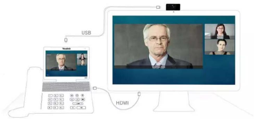
If you change the video layout on the IP phone, the content displayed on the external monitor will change as well.
The following figure shows an example of phone and external monitor screens display during a video call (receive presentations):
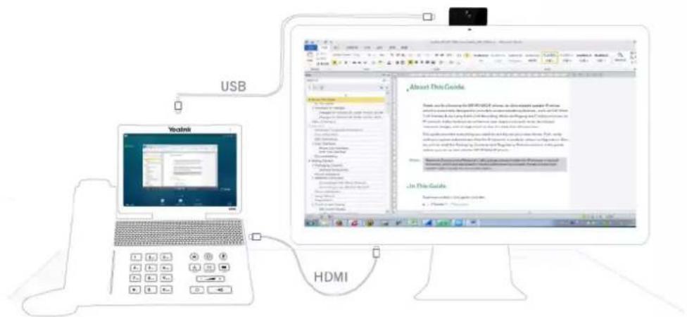
If the phone is not in a video call, the external monitor will display a Yealink logo. Before using the external monitor, ensure that the external monitor has been connected to your phone. For more information, refer to Phone Installation on page 35.
Note
The Extended Display Accessories ED10 is required for connecting the external monitor. You should purchase it separately. For more information, refer to Yealink Extended Display Accessories Quick Installation Guide for SIP VP-T49G.
The IP phone supports the following video resolutions on both IP phone and external monitor during the video call (not receive presentations) by default:
| Scenario | Resolution | |
| Receive | Send | |
| One-way video call | 1920 x 1080(1080P@30fps) | 1920 x 1080(1080P@30fps) |
| 3-way video conference | 1280 x 720(720P@30fps) | 1280 x 720(720P@30fps) |
The IP phone supports the following video and shared contents resolutions on both IP phone and external monitor during the video call (receive presentations) by default:
| Scenario | Resolution | ||
| Video | Shared Contents (Max) | ||
| Receive | Send | Receive | |
| One-way video call | 1280 x 720(720P@30fps) | 1280 x 720(720P@30fps) | 1920 x 1080(1080P@15fps) |
| 3-way video conference | 1280 x 720(720P@30fps) | 1280 x 720(720P@30fps) | 1920 x 1080(1080P@15fps) |
Note
The tables above list the video resolutions between SIP VP-T49G IP phone and Yealink IP phone.
You can configure the output resolution of the external monitor via web user interface.
To enable the external monitor via phone user interface, do one of the following:
- Tap ->Basic->HDMI.
Tap the EXT Display field.
Tap Enabled in the pop-up dialog box.
Tap the Save soft key.
- Swipe down from the top of the screen to enter the control center and toggle EXT Display on.
The EXT Display icon will display on the status bar of the touch screen.

Note
If you connect the external monitor, but disable the EXT Display, the external monitor will not display the content on the phone but a Yealink logo.
To configure the output resolution of external monitor via web user interface:
- Click on Settings->Video.
- Select the desired value from the pull-down list of Display.
If there is no external monitor connected, the pull-down list will only display No devices.

3. Click Confirm to accept the change.
Note
The output resolution of external monitor is configurable via web user interface only.
To disable the external monitor via phone user interface, do one of the following:
- Disconnect the monitor.
The touch screen prompts "Ext. Display disconnected".

- Tap ->Basic->HDMI.
Tap the EXT Display field.
Tap Disabled in the pop-up dialog box.
Tap the Save soft key.
- Swipe down from the top of the screen to enter the control center and toggle EXT Display off.
Redialing Numbers
To redial the last dialed number from your phone:
-
Press twice.
-
A call to your last dialed number is attempted.
To redial a previously dialed number from your phone:
-
Press Ⓞ when the phone is idle.
-
Tap the desired entry from the placed calls list.
Recent Call In Dialing
To view the placed calls list when the phone is on the dialing interface, you should enable recent call in dialing in advance.
To enable recent call in dialing via web user interface:
- Click on Directory->Setting.
- Select Enabled from the pull-down list of Recent Call In Dialing.
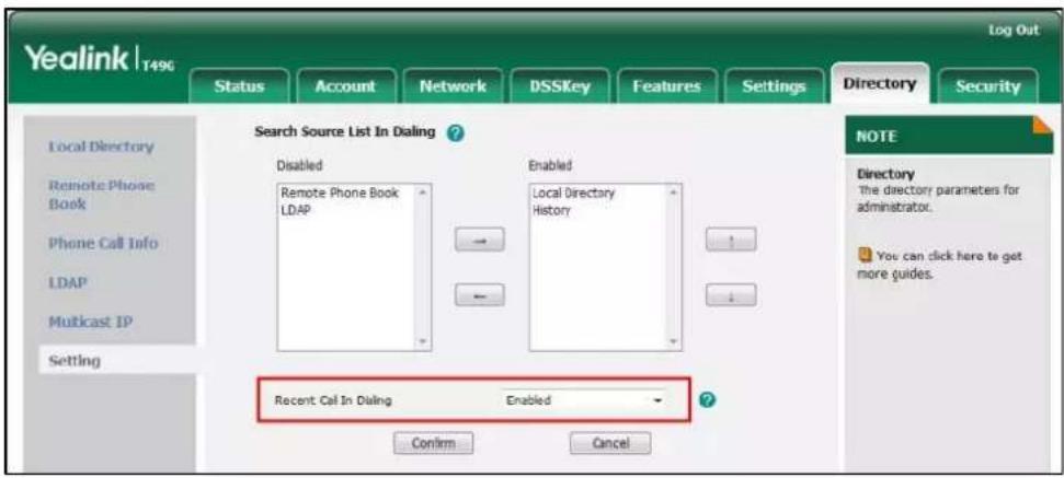
- Click Confirm to accept the change.
Note
Recent call in dialing is configurable via web user interface only.
To view placed calls list when the phone is on the dialing interface:
- Pick up the handset, press the Speakerphone key or tap the line key.
The touch screen displays the placed calls list.
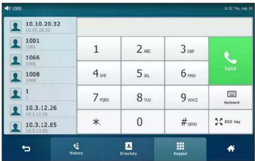
- Drag up and down to scroll through placed calls.
You can also enter a few continuous characters of the contact name or continuous numbers of the contact number (office, mobile or other number) to search from placed calls list.

Auto Answer
You can use auto answer to automatically answer an incoming call on a line. Auto answer is configurable on a per-line basis.
To configure auto answer via phone user interface:
- Tap ->Features->Auto Answer.
- Tap the On radio box in the desired line.

- Tap the Save soft key to accept the change or ↩ to cancel.
The icon AA will display on the status bar of the touch screen.

You can also swipe down from the top of the screen to enter the control center, tap Auto
Answer to turn to the Auto Answer setting screen, and then enable auto answer feature for the desired line.
Account auto answer for account is configurable via web user interface at the path Account->Basic.
Note
Auto answer for account is only applicable when there is no other call in progress on the phone.
Auto Redial
You can enable auto redial to automatically redial a phone number when the called party is busy. You can also configure the number of auto redial attempts and the time to wait between redial attempts.
To configure auto redial via phone user interface:
-
Tap ->Features->Auto Redial.
-
Tap the On radio box in the Auto Redial field.
-
Enter the desired time (in seconds) in the Redial Interval field.
The default value is "10".
- Enter the desired number of redial attempts in the Redial Times field.
The default value is "10".
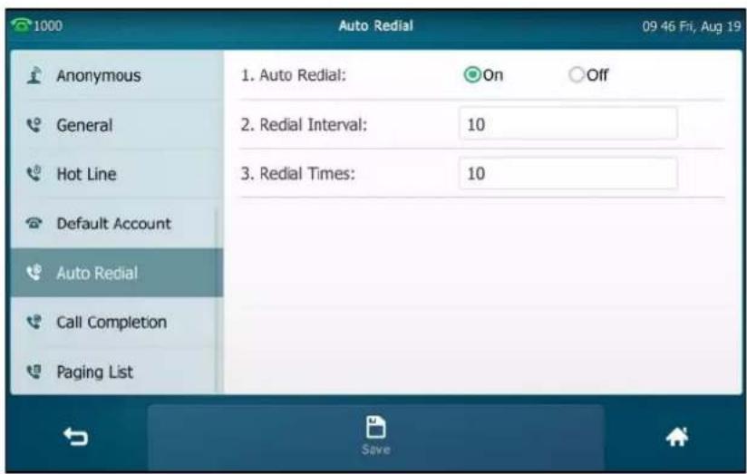
- Tap the Save soft key to accept the change or ↩ to cancel.
Auto redial is configurable via web user interface at the path Features->General Information.
To use auto redial:
When the called party is busy, the touch screen prompts the following:

- Tap OK to activate auto redial.
The touch screen prompts the following:
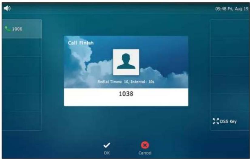
- Wait for the designated period of time or tap OK to redial the phone number.
The phone will retry as many times as configured until the called party is idle.
Call Completion
You can use call completion to notify the caller who failed to reach a desired party when the party becomes available to receive a call.
To enable call completion via phone user interface:
- Tap ->Features->Call Completion.
- Tap the On radio box in the Call Completion field.

- Tap the Save soft key to accept the change or ↩ to cancel.
Call completion is configurable via web user interface at the path Features->General Information.
To use call completion:
When the called party is busy, the following prompt will appear on the touch screen of the phone:

- Tap OK, the phone will then return to the idle screen and call completion will be activated.
When the called party becomes idle, the touch screen prompts the following:

- Tap OK to redial the number.
Note
Call completion is not available on all servers. For more information, contact your system administrator.
Recall
You can tap a recall key to place a call back to the last incoming call.
To configure a recall key via phone user interface:
- Tap ->Features->DSS Keys.
- Tap the desired line key.
- Tap the Type field.
- Tap Key Event in the pop-up dialog box.
- Tap the Key Type field.
- Tap ReCall in the pop-up dialog box.
- (Optional.) Enter the string that will appear on the touch screen in the Label field.
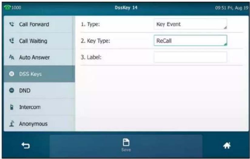
- Tap the Save soft key to accept the change or ↩ to cancel.
Recall key is configurable via web user interface at the path DSSKey->Line key.
Call Mute
You can mute the microphone of the active audio device during an active call so that the other party cannot hear you. Call mute applies to all modes (Handset, Headset and Speakerphone).
To mute a call:
- Press ① during an active call.
The touch screen indicates that the call is muted. The mute key LED illuminates solid red when the call is muted.
The following shows an audio-only call has been muted:
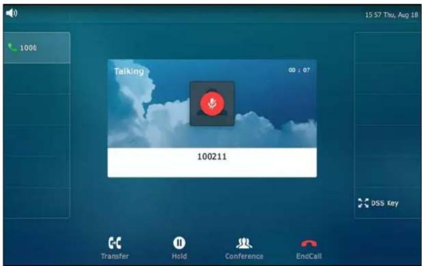
The following shows a video call has been muted:
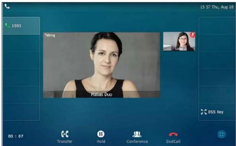
To un-mute a call:
- Press 📁 again to un-mute the call.
The mute key LED goes out.
Call Hold/Resume
You can place an active call on hold. Only one active call can be in progress on the phone at any time. Other calls can be made and received while placing the original call on hold. When you place a call on hold, your IP PBX may play music to the other party while waiting.
To place a call on hold:
1. Press 📁 or tap the Hold soft key during a call.
The following shows an audio-only call has been held:

The following shows a video call has been hold:

The phone will beep softly every 30 seconds to remind you that you still have a call on hold.
To resume a held call:
1. Press 📞 or tap the Resume soft key.
Multiple Calls on Hold:
If multiple calls are placed on hold, do one of the following:
- Tap the desired call, and then tap the Resume soft key to retrieve it.
- Tap the desired call, and then tap the corresponding line key to retrieve it.
Do Not Disturb (DND)
You can use DND to reject incoming calls automatically on the phone. The prompt message "n New Missed Call(s)" ("n" indicates the number of missed calls) will appear on the touch screen, and callers will receive a busy message. All calls you receive while DND is enabled are logged to your missed calls list.
Note
The prompt message will display only if Missed Call Log for the line is enabled. Missed call log is configurable via web user interface at the path Account->Basic->Missed Call Log.
Do not disturb is local to the phone, and may be overridden by the server settings. For more information, contact your system administrator.
You can enable/disable DND for the phone system, or you can customize DND for each or all accounts. Two DND modes:
• Phone (default): DND is effective for the phone system.
- Custom: DND can be configured for each or all accounts.
You can receive incoming calls from authorized numbers when DND is enabled.
To configure the DND mode via web user interface:
- Click on Features->Forward & DND.
- In the DND block, mark the desired radio box in the Mode field.
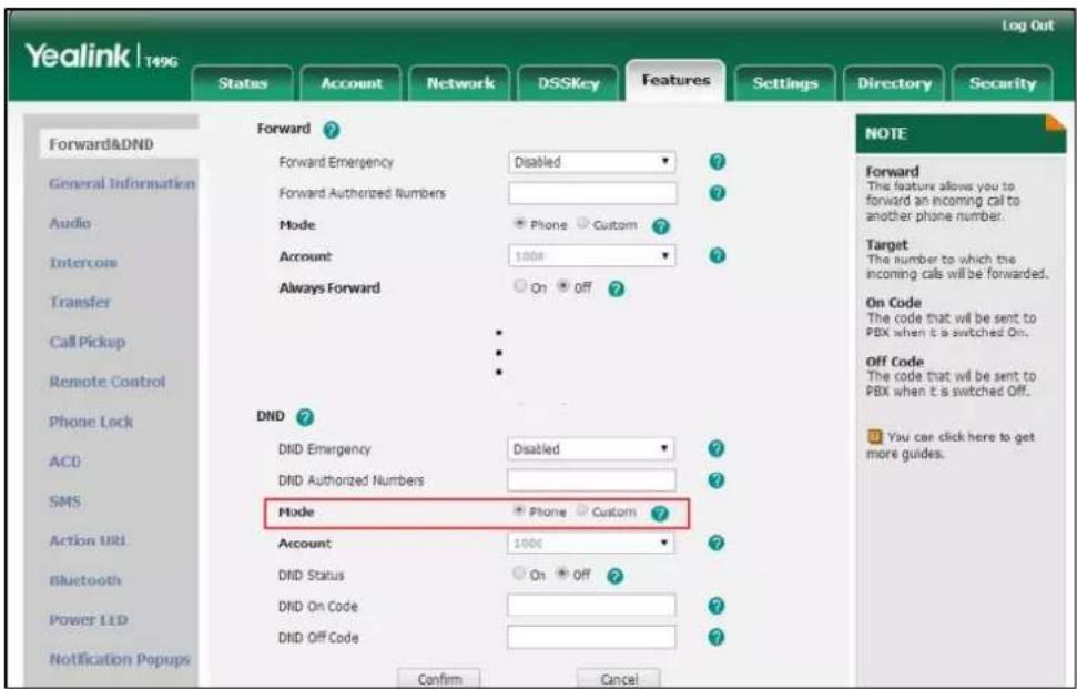
- Click Confirm to accept the change.
Note
DND mode is configurable via web user interface only.
To enable DND in phone mode:
1. Do one of the following:
- Tap - .
- Swipe down from the top of the screen to enter the control center and toggle DND on.
The icon — on the status bar indicates that DND is enabled.
Incoming calls will be rejected automatically and "n New Missed Call(s)" ("n" indicates the number of missed calls. e.g., 1 New Missed Call(s)) will appear on the touch screen.
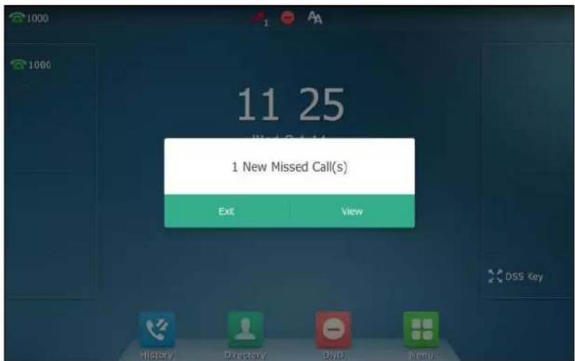
Note
When DND and busy forward are enabled in phone mode, all incoming calls will be forwarded to the configured destination number. For more information on busy forward, refer to Call Forward_ on page 198.
To enable DND in custom mode for a specific account:
1. Do one of the following:
- Tap - .
- Swipe down from the top of the screen to enter the control center and then tap DND.
The touch screen displays a list of accounts registered on the phone.
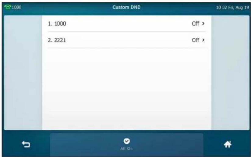
- Tap the desired account.
- Tap the On radio box in the Status field.
- (Optional.) Enter the DND on code or off code respectively in the On Code or Off Code field.

- Tap the Save soft key to accept the change.
If you enable DND for the default account, the associated line icon will change to
(for SIP account) or (for video conference platform account), and the icon will appear on the status bar.
If you enable DND for the non-default account, only the associated line icon will change to
(for SIP account) or (for video conference platform account), the icon will not appear on the status bar.
Incoming calls on the specific line will be rejected automatically, and the touch screen will prompt "n New Missed Call(s)" ("n" indicates the number of missed calls. e.g., 2 New Missed Call(s)).

Note
When DND and busy forward are enabled for a specific account, incoming calls on the specific account will be forwarded to the configured destination number. For more information on busy forward, refer to Call Forward on page 198.
To enable DND in custom mode for all accounts:
-
Do one of the following:
-
Tap - .
- Swipe down from the top of the screen to enter the control center and then tap DND. The touch screen displays a list of accounts registered on the phone.
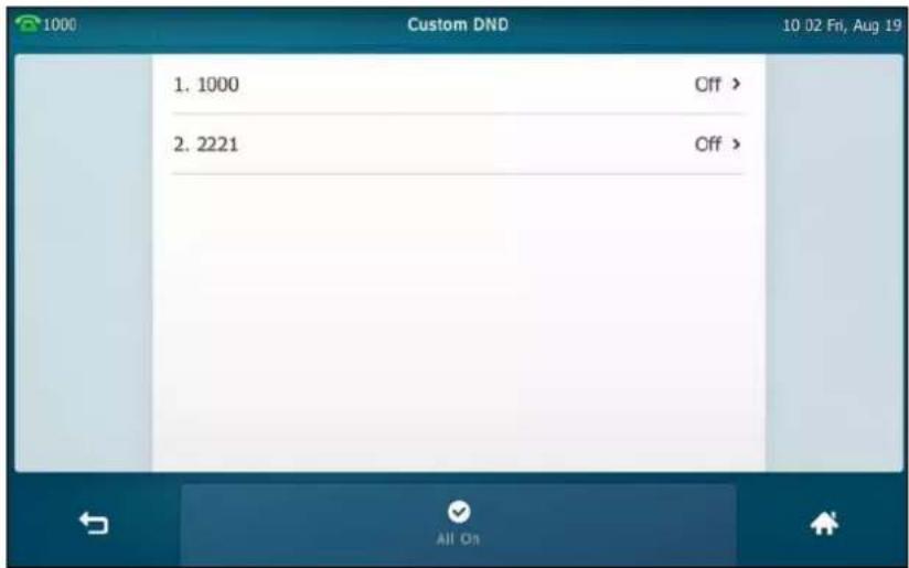
-
Tap the All On soft key to enable DND for all accounts.
-
Tap to return to the idle screen.
The icon — appears on the status bar, and all line icons change to 📞.
Incoming calls will be rejected automatically, and the touch screen will prompt "n New Missed Call(s)" ("n" indicates the number of the missed calls. e.g., 1 New Missed Call(s)).

To configure the DND authorized numbers via web user interface:
-
Click on Features->Forward & DND.
-
Select Enabled from the pull-down list of DND Emergency.
-
Enter the numbers in the DND Authorized Numbers field.
For multiple numbers, enter a comma between every two numbers.

- Click Confirm to accept the change.
When DND is enabled on the phone, the phone can still receive incoming calls from the numbers specified in the DND Authorized Numbers field.
Note
DND authorized number is configurable via web user interface only.
To disable DND in phone mode:
- Tap the DND soft key when the phone is idle.
To disable DND in custom mode:
- Tap the DND soft key when the phone is idle.
- Tap the desired account.
- Tap the Off radio box of the Status field.
- Tap the Save soft key to accept the change.
Call Forward
You can configure your phone to forward incoming calls to another party (static forwarding).
You can also forward calls while your phone is ringing (dynamic forwarding).
You can forward an incoming call to an international telephone number. This feature is enabled by default. Incoming calls from some authorized numbers not to be forwarded when the call forward feature is enabled. The incoming call will not be logged in the Forwarded Calls list. This feature is disabled by default.
Note
Call forward is local to the phone, and may be overridden by the server settings. For more information, contact your system administrator.
If DND feature is enabled, the incoming calls will not be forwarded even if you configure no answer forward feature.
Static Forwarding
Three types of static forwarding:
• Always Forward: Incoming calls are immediately forwarded.
- Busy Forward: Incoming calls are immediately forwarded if the phone is busy.
• No Answer Forward: Incoming calls are forwarded if not answered after a period of time.
You can enable/disable call forward for the phone system, or you can customize call forward for each or all accounts. Two call forward modes:
• Phone (default): Call forward is effective for the phone system.
- Custom: Call forward can be configured for each or all accounts.
To configure the call forward mode via web user interface:
- Click on Features->Forward & DND.
- In the Forward block, mark the desired radio box in the Mode field.

- Click Confirm to accept the change.
Note
Call forward mode is configurable via web user interface only.
To enable call forward in phone mode:
- Tap ->Features->Call Forward.
- Tap the desired forwarding type.
- Depending on your selection:
a) If you tap Always Forward:
1) Tap the On radio box in the Always Forward field.
2) Enter the destination number you want to forward all incoming calls to in the Forward To field.
3) (Optional.) Enter the always forward on code or off code respectively in the On Code or Off Code field.

b) If you tap Busy Forward:
1) Tap the On radio box in the Busy Forward field.
2) Enter the destination number you want to forward incoming calls to when the phone is busy in the Forward To field.
3) (Optional.) Enter the busy forward on code or off code respectively in the On Code or Off Code field.

c) If you tap No Answer Forward:
1) Tap the On radio box in the No Answer Forward field.
2) Enter the destination number you want to forward unanswered incoming calls to in the Forward To field.
3) Tap the After Ring Time field.
4) Tap the desired ring time to wait before forwarding from the pull-down list. The default ring time is 12 seconds.
5) (Optional.) Enter the no answer forward on code or off code respectively in the On Code or Off Code field.

- Tap the Save soft key to accept the change or ↩ to cancel.
The icon 📋 on the status bar indicates that the call forward is enabled.
You can also swipe down from the top of the screen to enter the control center, tap FWD to turn to the desired call forward setting screen according to the current forward type. If you have not configured the call forward type, tapping FWD will turn to the Always Forward setting screen.
To enable call forward in custom mode:
-
Do one of the following:
-
Tap -> Features->Call Forward.
- Press ⬤ when the phone is idle.
- Swipe down from the top of the screen to enter the control center and then tap FWD.
- Tap the desired account.

-
Tap the desired forwarding type.
-
Depending on your selection:
a) If you tap Always Forward:
1) Tap the On radio box in the Always Forward field.
2) Enter the destination number you want to forward all incoming calls to in the Forward To field.
3) (Optional.) Enter the always forward on code or off code respectively in the On Code or Off Code field.
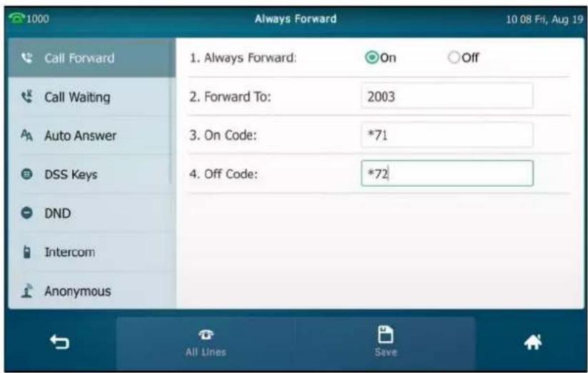
You can also enable always forward for all accounts. Do the following:
1) Tap the All Lines soft key.
The touch screen prompts "Copy to all lines?".

2) Tap OK to accept the change or Cancel to cancel.
b) If you select Busy Forward:
1) Tap the On radio box in the Busy Forward field.
2) Enter the destination number you want to forward incoming calls to when the phone is busy in the Forward To field.
3) (Optional.) Enter the busy forward on code or off code respectively in the On Code or Off Code field.

You can also enable busy forward for all accounts. Do the following:
1) Tap the All Lines soft key.
The touch screen prompts "Copy to all lines?".

2) Tap OK to accept the change or Cancel to cancel.
c) If you select No Answer Forward:
1) Tap the On radio box in the No Answer Forward field.
2) Enter the destination number you want to forward unanswered incoming calls to in the Forward To field.
3) Tap the After Ring Time field.
4) Tap the desired ring time to wait before forwarding from the pull-down list.
The default ring time is 12 seconds.
5) (Optional.) Enter the no answer forward on code or off code respectively in the On Code or Off Code field.
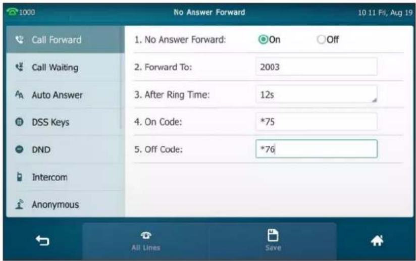
You can also enable no answer forward for all accounts. Do the following:
1) Tap the All Lines soft key.
The touch screen prompts "Copy to all lines?".
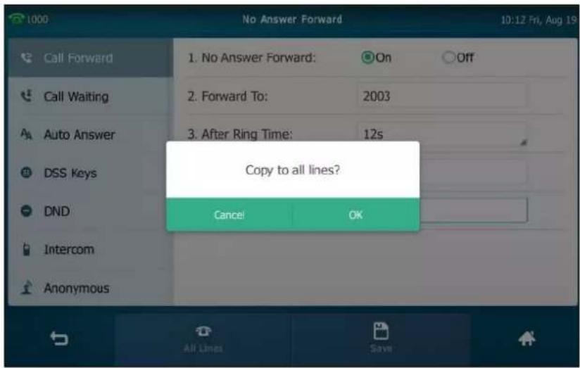
2) Tap OK to accept the change or Cancel to cancel.
- Tap the Save soft key to accept the change.
If you activate call forward for the default account, the associated line icon will change to
(for SIP account) or (for video conference platform account), and the icon

will appear on the status bar.
If you activate call forward for the non-default account, only the associated line icon will change to 📞 (for SIP account) or 📞 (for video conference platform account), the icon 📞 will not appear on the status bar.
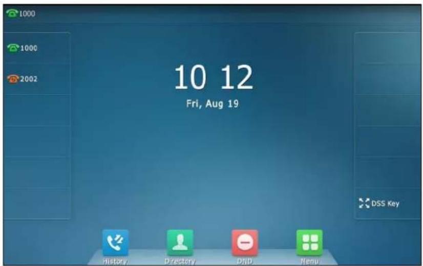
Call forward is configurable via web user interface at the path Features->Forward & DND.
Note
You can also enter the SIP URI or IP address in the Forward To field. For more information on using the SIP URI or IP address, refer to Placing Calls on page 162.
Call forward is local to the phone, and may be overridden by the server settings. Call forward on code or off code may be different among servers. For more information, contact your system administrator.
To configure the forward authorized numbers via web user interface:
- Click on Features->Forward & DND.
- Select Enabled from the pull-down list of Forward Emergency.
- Enter the numbers in the Forward Authorized Numbers field.
For multiple numbers, enter a comma between every two numbers.

4. Click Confirm to accept the change.
When call forward is enabled on the phone, the phone cannot forward incoming calls from the numbers specified in the Forward Authorized Numbers field.
Note
Forward authorized number is configurable via web user interface only.
To disable call forward in phone mode:
Do one of the following:
- Tap ->Features->Call Forward.
Tap the desired forwarding type.
Tap the Off radio box.
Tap the Save soft key to accept the change.
- Press ⬤ when the phone is idle.
- Swipe down from the top of the screen to enter the control center, and then tap FWD.
To disable call forward in custom mode for a specific account:
-
Do one of the following:
-
Tap -> Features->Call Forward.
- Press ⬤ when the phone is idle.
- Swipe down from the top of the screen to enter the control center and then tap FWD.
The touch screen displays a list of accounts registered on the phone.
- Tap the desired account.
- Tap the desired forwarding type.
- Tap the Off radio box.
- Tap the Save soft key to accept the change.
Dynamic Forwarding
To forward an incoming call to another party:
- When the phone is ringing, tap the FWD soft key.
- Enter the number you want to forward the incoming call to.
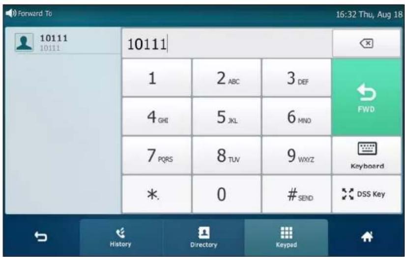
- Press #sBD or tap FWD.
The touch screen prompts a call forward message.
Note
When the phone forwards a call, the forward call prompt window will pop up by default, if you want to disable the feature, contact your system administrator for more information.
Call Transfer
You can transfer a call to another party in one of three ways:
- Blind Transfer: Transfer a call directly to another party without consulting.
- Semi-Attended Transfer: Transfer a call when the target phone is ringing.
- Attended Transfer: Transfer a call with prior consulting.
Blind Transfer
Before performing a blind transfer (except you use dial number method), make sure that the transfer mode via dsskey is configured as Blind Transfer.
To perform a blind transfer:
-
Press 📄 or tap the Transfer soft key during a call.
-
Do one of the following:
- Enter the number you want to transfer the call to.
Press ⬤ to complete the transfer.
- Enter the number you want to transfer the call to.
Tap Transfer.

The phone will prompt a dialog box as the following picture shows:
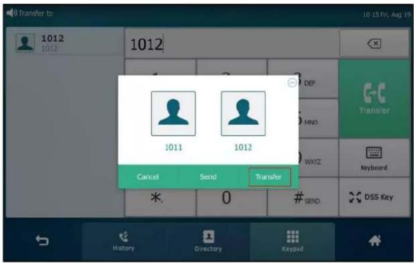
Tap Transfer to complete the transfer. (The call will automatically dial out in about 5 seconds if you do not tap Transfer.)
- Tap Directory, and then tap Local Directory. Search for the contact and tap the desired contact to complete the transfer.
- Tap Directory, and then tap Remote Phone Book. Search for the contact and tap the desired contact to complete the transfer. (Remote phone book should be configured in advance, refer to Remote Phone Book on page 109 for more information.)
- Tap History, and then tap the desired list. Tap the desired entry to complete the transfer.
The call is then connected to the number to which you are transferring.
Semi-Attended Transfer
Before performing a semi-attended transfer (except you use dial number method), make sure that the transfer mode via dsskey is configured as New Call or Attended Transfer. For more information on how to configure it, refer to Configuring Transfer Mode via Dsskey on page 232.
To perform a semi-attended transfer:
-
Press ☐ or tap the Transfer soft key during a call.
-
Do one of the following:
- Enter the number you want to transfer the call to.
Press #info to dial out.
- Enter the number you want to transfer the call to.
Tap Transfer. The phone will prompt a dialog box. Tap Send to dial out. (The call will automatically dial out in about 5 seconds if you do not tap Send.)
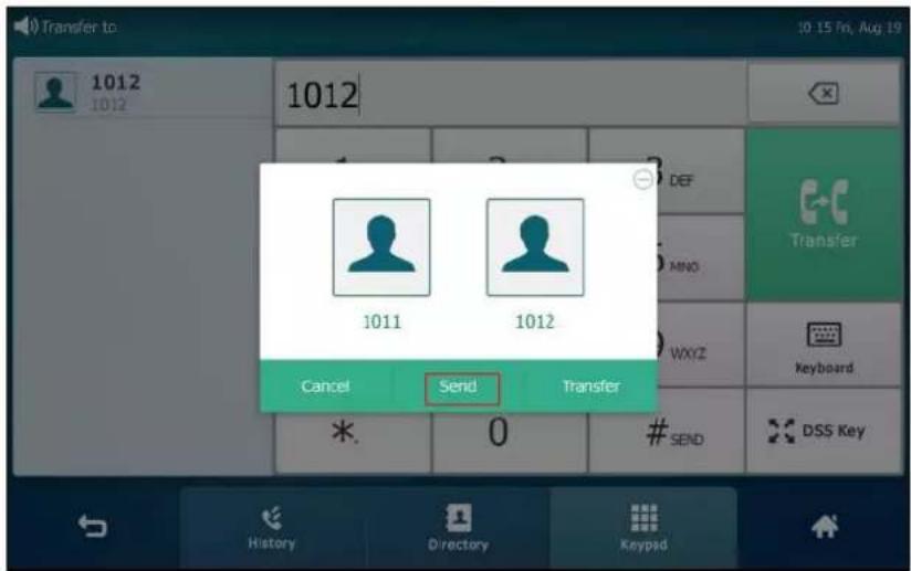
- Tap Directory, and then tap Local Directory. Search for the contact and tap the desired contact to dial out.
- Tap Directory, and then tap Remote Phone Book. Search for the contact and tap the desired contact to dial out. (Remote phone book should be configured in advance, refer to Remote Phone Book on page 109 for more information.)
-
Tap History, and then tap the desired list. Tap the desired entry to dial out.
-
Press C-C or tap the Transfer soft key to complete the transfer when receiving ringback. If you are using a handset, the transfer can be completed by hanging up the handset.
Attended Transfer
Before performing an attended transfer (except you use dial number method), make sure that the transfer mode via dsskey is configured as New Call or Attended Transfer. For more information on how to configure it, refer to Configuring Transfer Mode via Dsskey on page 232.
To perform an attended transfer:
- Press ☐ or tap the Transfer soft key during a call.
- Do one of the following:
- Enter the number you want to transfer the call to.
Press #sBD to dial out.
- Enter the number you want to transfer the call to.
Tap Transfer. The phone will prompt a dialog box. Tap Send to dial out. (The call will automatically dial out in about 5 seconds if you do not tap Send.)
- Tap Directory, and then tap Local Directory. Search for the contact and tap the desired contact to dial out.
- Tap Directory, and then tap Remote Phone Book. Search for the contact and tap the desired contact to dial out. (Remote phone book should be configured in advance, refer to Remote Phone Book on page 109 for more information.)
-
Tap History, and then tap the desired list. Tap the desired entry to dial out.
-
After the party answers the call, press or tap Transfer soft key to complete the transfer.
If you are using a handset, the transfer can be completed by hanging up the handset.
Call Waiting
You can enable or disable call waiting on the phone. If call waiting is enabled, you can receive another call when there is already an active call on the phone. Otherwise, another incoming call is automatically rejected by the phone with a busy message when there is an active call on the phone. You can also enable or disable the phone to play a warning tone when receiving another call.
To configure call waiting via phone user interface:
- Tap ->Features->Call Waiting.
- Tap the On radio box in the Call Waiting field.
- Tap the On radio box in the Play Tone field.
- (Optional.) Enter the call waiting on code or off code respectively in the On Code or Off Code field.
If on code or off code is configured, the IP phone will send the corresponding code to activate or deactivate call waiting on the server. They may vary on different servers.

- Tap the Save soft key to accept the change or ↩ to cancel.
Call waiting is configurable via web user interface at the path Features->General Information.
Conference
You can use the SIP VP-T49G IP phone to create a conference using the phone's local conference and network conference. During a conference, you can manage each participant. You can mute, hold and remove individual participants in the video call screen. For more information on the video call screen, refer to Video Call Screen Display on page 43.
Note
Network conference is not available on all servers. For more information, contact your system administrator.
Local Conference
You can create up to three-way video conference call and five-way audio-only and video mixed conference. The audio-only and video mixed conference supports five parties participated (including yourself) at the same time including a maximum of three video calls.
The following figure shows what the touch screen looks like in a mixing conference call with three video calls and two audio-only calls:

To set up a local conference call:
- Place a call to the first party.
- When the first party answers the call, tap the Conference soft key to place a new call. The active call is placed on hold.
-
Enter the number of the second party, and then press #ABD or tap Conference.
-
When the second party answers the call, tap the Conference soft key on the second party call screen to join all parties in the conference.
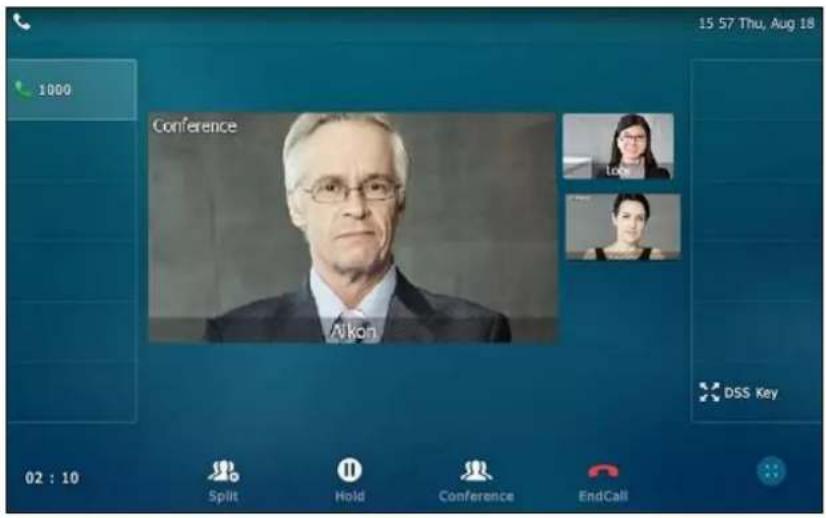
- Repeat steps 2 to 4 until you have added all intended parties.
Note
The phone will enter the video call full-screen within 5 seconds during a call, you may tap blank area at the top or bottom of the screen to see the soft keys.

To join calls in a conference:
- Make sure you have an active call and one or more calls are on hold (either on the same line key or a different line key).
- Tap the desired call for conference and ensure that the call is active.
- Tap the Conference soft key.
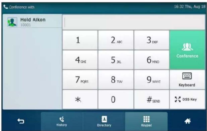
- Tap the Hold call to join the calls in the conference.

- Repeat steps 3, 4 to join more calls in the conference.
During the conference call, you can do the following:
- Press 📂 or tap the Hold soft key to place the conference call on hold.
• Tap the Conference soft key to place a new call. - Tap the Split soft key to split the conference call into individual calls on hold.
- Press 📋 to mute the conference call, all other participants can hear each other, but they cannot hear you.
- Tap the EndCall soft key to drop the conference call.
- Long tap the desired party (if the far site only supports audio-only call, you can just tap it), the phone will prompt a dialog box as the following picture shows:
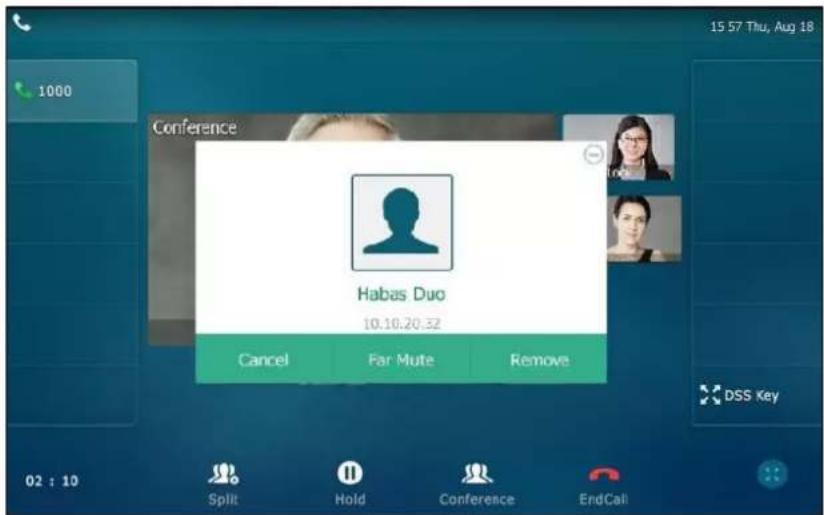
You can do the following:
Tap Far Mute to mute the party. The muted party can hear everyone, but no one can
hear the muted party.
- Tap Remove to remove the party.
- Tap Cancel or ⏻ to close the dialog box.
Network Conference
You can use network conference feature on the SIP VP-T49G IP phone to conduct an audio-only/video/audio-only and video mixed conference with multiple participants.
This feature allows you to perform the following:
- Join calls together in a conference call.
- Invite other party into an active conference call.
To use this feature, contact your system administrator for the network conference URI in advance.
Note
Network conference is not available on all servers. Contact your system administrator for more information.
To configure network conference via web user interface:
- Click on Account->Advanced.
- Select the desired account from the pull-down list of Account.
- Select Network Conference from the pull-down list of Conference Type.
- Enter the conference URI (e.g., conference@example.com) in the Conference URI field.

- Click Confirm to accept the change.
Note
Network conference is configurable via web user interface only.
To set up a network conference call:
- Place a call to the first party.
- Tap the Conference soft key to place a new call.
The active call is placed on hold. - Enter the number of the second party and press #sBO or tap Conference.
- When the second party answers the call, tap the Conference soft key to add the second party to the conference.
- Tap the Conference soft key to place a new call.
The conference call is placed on hold. - Enter the number of the new party and then press #info or tap Conference.
- When the new party answers the call, tap the Conference soft key to add the new party to the conference.
- Repeat steps 5 to 7 until you have added all intended parties.
The procedures to set up a network conference call on specific servers may be different from introduced above. Contact your system administrator for more information.
Call Park
You can use call park to place a call on hold, and then retrieve the call from another phone in the system (for example, a phone in another office or conference room). You can park an active call by tapping the call park key on the phone. If the call is parked successfully, the response is either a voice prompt confirming that the call was parked, or a visible prompt on the touch screen.
Note
Call park is not available on all servers. Contact your system administrator for more information.
To configure a call park key via phone user interface:
-
Tap ->Features->DSS Keys.
-
Tap the desired line key.
-
Tap the Type field.
-
Tap Key Event in the pop-up dialog box.
-
Tap the Key Type field.
-
Tap Call Park in the pop-up dialog box.
-
Tap the Account ID field.
-
Tap the desired line in the pop-up dialog box.
- (Optional.) Enter the string that will appear on the touch screen in the Label field.
- Enter the call park code in the Value field.

- Tap the Save soft key to accept the change or ↩ to cancel.
Call park key is configurable via web user interface at the path DSSKey->Line Key.
To use call park:
- User on phone A places a call to phone B.
- User on phone A wants to take the call in a conference room for privacy, and so taps the call park key on phone A.
- User on phone A walks to an available conference room where the phone is designated as phone C. The user dials the call park retrieve code to retrieve the parked call.
The system establishes the call between phone C and B.
Note
The call park code and call park retrieve code are predefined on the system server. Contact your system administrator for more information.
If the parked call is not retrieved within a period of time assigned by the system, the phone performing call park will receive a call back.
Call Pickup
You can use call pickup to answer someone else's incoming call on your phone. The SIP VP-T49G IP phone supports directed call pickup and group call pickup. Directed call pickup is used for picking up a call that is ringing at a target phone number. Group call pickup is used for picking up a call that is ringing at any phone number in a certain group. The pickup group should be predefined, contact your system administrator for more information.
You can pick up an incoming call by tapping DPickup/GPickup on the dialing screen. To use call pickup, you need to configure the call pickup code beforehand on a global or per-line basis
via web user interface. The call pickup code configured on a per-line basis takes precedence over that configured on a global basis.
Note
If there are many incoming calls at the same time, tapping the GPickup on the phone will pick up the call that rings first.
Directed Call Pickup
To enable directed call pickup and configure the directed call pickup code on a global basis via web user interface:
- Click on Features->Call Pickup.
- Select Enabled from the pull-down list of Directed Call Pickup.
- Enter the directed call pickup code in the Directed Call Pickup Code field.

- Click Confirm to accept the change.
To configure the directed call pickup code on a per-line basis via web user interface:
- Click on Account->Advanced.
-
Select the desired account from the pull-down list of Account.
-
Enter the directed call pickup code in the Directed Call Pickup Code field.
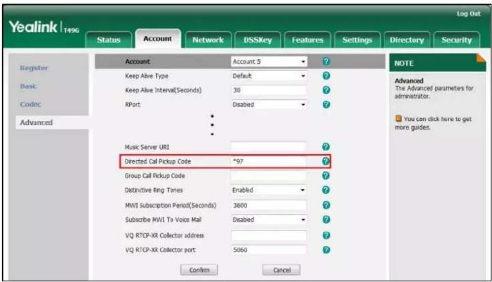
- Click Confirm to accept the change.
To pick up a call directly:
- Pick up the handset, press the Speakerphone key or tap the line key.
DPickup appears on the onscreen keyboard.
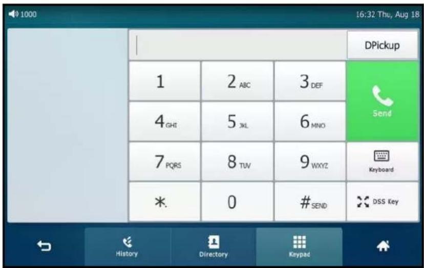
- Tap DPickup on your phone when the target phone receives an incoming call.
- Enter the phone number which is receiving an incoming call.
- Tap DPickup again.
The call is answered on your phone.
You can also configure a line key as a direct pickup key via phone user interface or web user interface. Once configured, you can pick up a call by tapping the direct pickup key directly. For more information, refer to Line Keys on page 136.
Group Call Pickup
To enable group call pickup and configure the group call pickup code on a global basis via web user interface:
- Click on Features->Call Pickup.
- Select Enabled from the pull-down list of Group Call Pickup.
- Enter the group call pickup code in the Group Call Pickup Code field.

- Click Confirm to accept the change.
To configure the group call pickup code on a per-line basis via web user interface:
- Click on Account->Advanced.
- Select the desired account from the pull-down list of Account.
- Enter the group call pickup code in the Group Call Pickup Code field.

- Click Confirm to accept the change.
To pick up a call in the group:
- Pick up the handset, press the Speakerphone key or tap the line key.
GPickup appears on the onscreen keyboard.
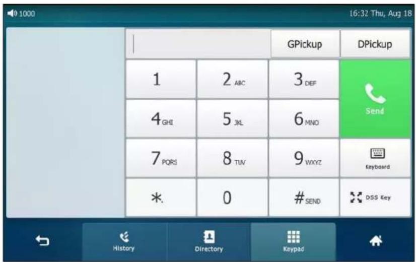
- Tap GPickup on your phone when a phone in the group receives an incoming call.
The call is answered on your phone.
You can also configure a line key as a group pickup key via phone user interface or web user interface. Once configured, you can pick up a call by tapping the group pickup key directly.
Note
The directed call pickup code and group call pickup code are predefined on the system server. Contact your system administrator for more information.
Anonymous Call
You can use anonymous call to block your identity and phone number from appearing to the called party when you call someone. For example, you want to call to consult some of the services, but don't want to be harassed. Anonymous call is configurable on a per-line basis. You can also configure the phone to send anonymous call on/off code to the server to activate/deactivate anonymous call on the server side.
Note
Anonymous call is not available on all servers. Contact your system administrator for the anonymous call on code and off code.
To configure anonymous call via phone user interface:
-
Tap ->Features->Anonymous.
-
Tap the desired line.
- Tap the On radio box in the Local Anonymous field.
- (Optional.) Tap the On Code or Off Code radio box in the Send Anony Code field.
- (Optional.) Enter the anonymous call on code and off code respectively in the On Code and Off Code field beneath the Send Anony Code field.
The phone will send the configured on code or off code depending on your selection when you enable or disable anonymous call feature on the phone.
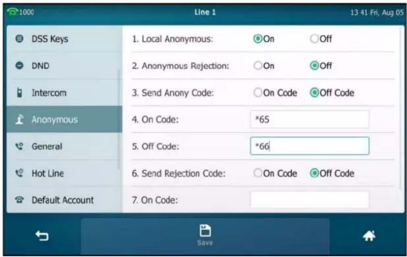
- Tap the Save soft key to accept the change or ↩ to cancel.
Anonymous call is configurable via web user interface at the path Account->Basic.
To place an anonymous call:
- Using the specific line on the phone to place a call to phone B.
The touch screen of phone B prompts an incoming call from anonymous.

Anonymous Call Rejection
You can use anonymous call rejection to reject incoming calls from anonymous callers.
Anonymous call rejection automatically rejects incoming calls from callers who deliberately block their identities and numbers from being displayed. Anonymous call rejection is configurable on a per-line basis. You can also configure the phone to send anonymous call rejection on/off code to the server to activate/deactivate anonymous call rejection on the server
side.
To configure anonymous call rejection via phone user interface:
-
Tap ->Features->Anonymous.
-
Tap the desired line.
-
Tap the On radio box in the Anonymous Rejection field.
-
(Optional.) Tap the On Code or Off Code radio box in the Send Rejection Code field.
-
(Optional.) Enter the anonymous call rejection on code and off code respectively in the On Code and Off Code field beneath the Send Rejection Code field.
The phone will send the configured on code or off code depending on your selection when you enable or disable anonymous call rejection feature on the phone.
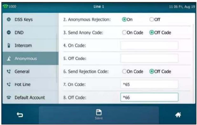
- Tap the Save soft key to accept the change or ↩ to cancel.
Anonymous call rejection is configurable via web user interface at the path Account->Basic.
If phone B has anonymous call feature enabled and places a call to your phone, the call will be rejected, and the touch screen of the phone B will display the following:

Capturing Screenshots during a Video Call
You can capture the screenshots during a video call via phone user interface. Before capturing the screenshot, ensure that the USB flash drive has been connected to your phone. The USB flash drive can store the screenshots.
The screenshots are saved in *.jpg format and include a date & time stamp and the other party's number/IP address/name (or the first person's number/IP address/name you called), for example, 20150731-1630-Mishoel.jpg was created on July 31, 2015, at 16:30 and you have a call with Mishoel.
Note
If the call is audio-only, you cannot capture the screenshot.
To capture screenshots during a video call via phone user interface, do one of the following:
- Tap the More soft key.

Tap the Screenshot soft key if you want to capture the picture.
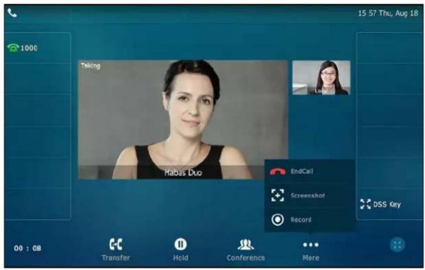
- Press

The status bar prompts "Screenshot has been saved to the USB device successfully."

You can view the screenshots that stored in the USB flash drive. For more information, refer to Viewing the Pictures Stored in Your USB Flash Drive on page 226.
Note
If you want to remove the USB flash drive, please wait until the status bar prompts "Screenshot has been saved to the USB device successfully.".
When you connect a USB flash drive to your phone, you have to tap More->EndCall to end a call.
To delete screenshots via phone user interface:
- Tap ->USB->Browse Photo.
2. Do one of the following:
- Tap 📋 after the screenshot you want to delete.
- Tap the desired screenshot to preview, and then tap Delete.
The phone prompts "Delete this photo?"

- Tap OK to accept the change or Cancel to cancel.
Viewing the Pictures Stored in Your USB Flash Drive
You can view the pictures that are stored in your USB flash drive at any time. You can display your pictures as lists, or display just one picture. Before displaying the pictures, ensure that the USB flash drive has been connected to your phone. For more information, refer to Phone Installation on page 35.
To view pictures stored in the USB flash drive via phone user interface:
1. Tap ->USB->Browse Photo.
Your pictures will display as lists.
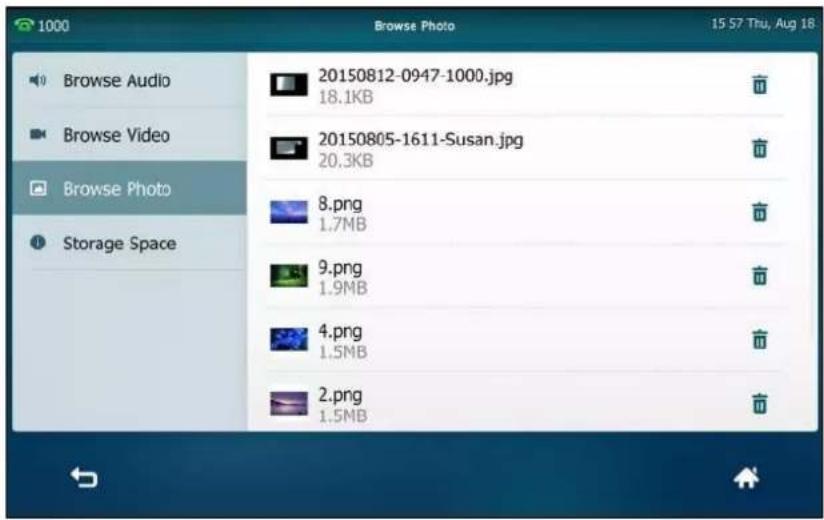
- Tap the desired photo to view.
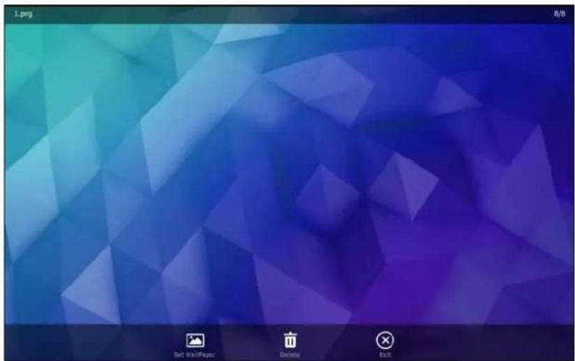
You can do one of the following:
Tap Set Wallpaper to set the picture as the wallpaper for your phone. For more information, refer to Setting Wallpaper on page 67.
- Tap Delete to delete the picture.
The touch screen prompts "Delete this photo?".

Tap OK to accept the change.
- Tap Exit to stop displaying the picture.
- Swipe left or right to view the next picture or previous picture.
Note
The soft keys (Set Wallpaper, Delete and Exit) are hidden after they display 5 seconds, unless you tap the touch screen.
Advanced Phone Features
This chapter provides operating instructions for the advanced features of the SIP VP-T49G IP phone. Topics include:
- Busy Lamp Field (BLF)
- BLF List
- Call and Conference Recording Using a USB Flash Drive
- Call Recording Using a Record Key
- Hot Desking
- Intercom
- Multicast Paging
- Music on Hold
• Shared Call Appearance (SCA) - Messages
• Video Conferencing Features
If you require additional information or assistance with your new phone, contact your system administrator.
Busy Lamp Field (BLF)
You can use BLF to monitor a specific line for status changes on the phone. For example, you can configure a BLF key on the phone to monitor the status of a friend's line (busy or idle). The BLF key icon illuminates solid red when the friend's line is in use. For more information, contact your system administrator.
Configuring the BLF Feature on the Phone
You need to configure the IP phone to perform BLF monitoring. IP phones being monitored do not require any configuration.
Configuring a BLF Key
To configure a BLF key via phone user interface:
-
Tap ->Features->DSS Keys.
-
Tap the desired line key.
-
Tap the Type field.
-
Tap BLF in the pop-up dialog box.
-
Tap the Account ID field.
-
Tap the desired line in the pop-up dialog box.
-
(Optional.) Enter the string that will appear on the touch screen in the Label field.
-
Enter the phone number or extension you want to monitor in the Value field.
-
(Optional.) Enter the directed call pickup code in the Extension field.
If it is configured, when the monitored user receives an incoming call, the supervisor can tap the BLF key to pick up the call directly.
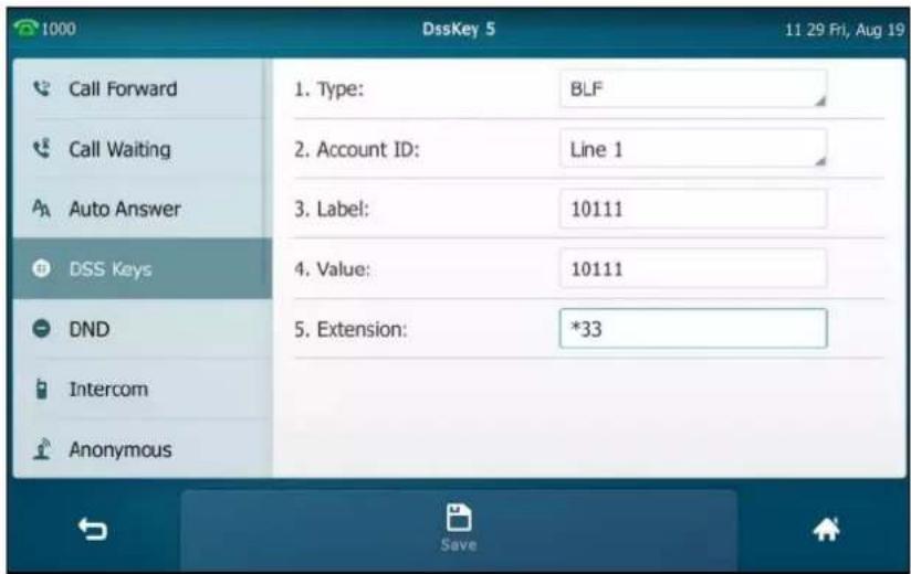
- Tap the Save soft key to accept the change or ↩ to cancel.
BLF key is configurable via web user interface at the path DSSKey->Line key.
Configuring Visual and Audio Alert for BLF pickup
You can enable audio alert feature for BLF pickup on the phone. This allows the monitoring phone to play a warning tone when the monitored line receives an incoming call. You can also enable visual alert feature for BLF pickup on the phone. This allows the touch screen of the monitoring phone to display the caller ID when the monitored line receives an incoming call.
To enable visual and audio alert features via web user interface:
-
Click on Features->Call Pickup.
-
Select Enabled from the pull-down list of Visual Alert for BLF Pickup.
3. Select Enabled from the pull-down list of Audio Alert for BLF Pickup.

4. Click Confirm to accept the change.
Note
Visual and audio alert features are configurable via web user interface only.
When the monitored line receives an incoming call, the following occurs on your phone:
- The phone plays a warning tone (if enabled).
• The BLF key icon flashes red. - The caller ID appears on the touch screen (if enabled).
In the following figure, the touch screen shows an incoming call from 1058 on the monitored line.
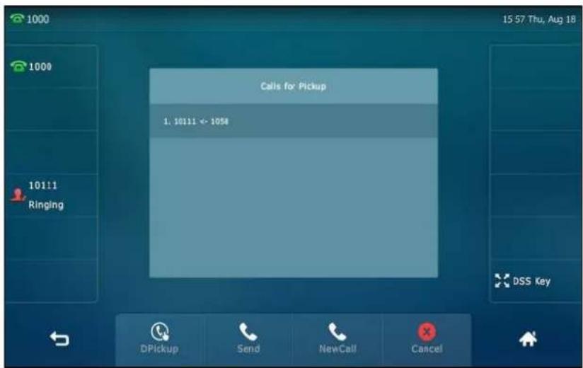
You can do the following actions:
- Tap the DPickup soft key to pick up the call.
- Tap the Send soft key to dial out the monitored phone number.
- Tap the NewCall soft key to place a new call.
- Tap the Cancel soft key to exit the screen.
Note
If your phone is locked, you cannot use the DPickup, Send, NewCall and Cancel soft keys until unlocked. For more information refer to Phone Lock on page 81.
Configuring Transfer Mode via Dsskey
When there is an active call on the IP phone, you can handle the active call differently depending on the configuration of the transfer mode via dsskey.
To configure the transfer mode via dsskey via web user interface:
- Click on Features->Transfer.
- Select the desired transfer mode from the pull-down list of Transfer Mode via Dsskey.
- If you select Blind Transfer, tap the BLF key to blind transfer the call to the monitored user.
- If you select Attended Transfer, tap the BLF key to dial out the monitored phone number and then perform an attended or a semi-attended transfer.
- If you select New Call, tap the BLF key to place a new call to the monitored user. The original call is placed on hold.

- Click Confirm to accept the change.
Configuring Directed Call Pickup Code
If you configure the directed call pickup code in advance, you can pick up the monitored user's incoming call by tapping the BLF key. You can configure the directed call pickup code when configuring a BLF key. For more information, refer to Configuring a BLF Key on page 229. You can also configure the directed call pickup code on a global or per-line basis via web user
interface.
If you enable visual alert feature, you can also pick up the monitored user's incoming call by tapping DPickup soft key. To use DPickup soft key to pick up the call, the call pickup code can only be configured on a global or per-line basis via web user interface.
Note
The pickup code is used in the following order of preference: Extension (DSSKey->Line Key)>Directed Call Pickup Code (Account->Advanced)>Directed Call Pickup Code (Features->Call Pickup). If pickup code is not configured, tapping the BLF key/DPickup soft key will directly call the monitored user when he/she receives an incoming call.
To configure directed call pickup feature on a global basis via web user interface:
- Click on Features->Call Pickup.
- Enter the desired pickup code in the Directed Call Pickup Code field.

- Click Confirm to accept the change.
To configure the directed call pickup code on a per-line basis via web user interface:
- Click on Account->Advanced.
-
Select the desired account from the pull-down list of Account.
-
Enter the desired pickup code in the Directed Call Pickup Code field.

- Click Confirm to accept the change.
Using BLF Feature on the Phone
You can use the BLF key in the following ways:
- Place a call to the monitored user.
- Transfer a call to the monitored user.
- Pick up an incoming call of the monitored user.
Placing a Call to the Monitor User
You can tap a BLF key to dial out the monitored phone number when the monitored line is idle.
To place a call to the monitored user when the IP phone is idle:
- Tap the BLF key.
The IP phone dials out the phone number of the monitored user.
Transferring a Call to the Monitored User
When there is already an active call on the IP phone, you can transfer the active call to the monitored user by tapping the BLF key. The phone handles the active call differently depending on the configuration of the transfer mode via dsskey with the BLF key (refer to Configuring
Transfer Mode via Dsskey). The transfer mode via dsskey has the following modes:
- Blind Transfer
- Attended Transfer
- New Call
To perform a blind transfer:
When the transfer mode via dsskey is set to Blind Transfer and there is already an active call on the IP phone, you can do the following:
- Tap the BLF key of the monitored user which you want to transfer this call to.
Then the active call is connected to the number of the monitored user.
To perform a semi-attended transfer:
When the transfer mode via dsskey is set to Attended Transfer and there is already an active call on the IP phone, you can do the following:
-
Tap the BLF key of the monitored user which you want to transfer this call to. The phone will dial the number of the monitored user.
-
Tap the BLF key of the monitored user again or the Transfer soft key to complete the transfer when receiving ringback.
To perform an attended transfer:
When the transfer mode via dsskey is set to Attended Transfer and there is already an active call on the IP phone, you can do the following:
-
Tap the BLF key of the monitored user which you want to transfer this call to. The phone will dial the number of the monitored user.
-
Tap the BLF key of the monitored user again or the Transfer soft key to complete the transfer after the monitored user answers the call.
To perform a new call:
When the transfer mode via dsskey is set to New Call and there is already an active call on the IP phone, you can do the following:
- Tap the BLF key of the monitored user you want to call.
The phone will dial the number of the monitored user. The original call is placed on hold.
Picking up an Incoming Call of the Monitored User
When the monitored user receives an incoming call, the BLF key icon of the monitored user will become 📁 and flashing. You can use the BLF key to pick up an incoming call of the monitored user. If you enable visual alert feature on the phone, you can pick up the incoming call using the DPickup soft key. Before picking up an incoming call, ensure that the directed call pickup code has been configured in advance.
To pick up an incoming call using the BLF key or the DPickup soft key:
1. Tap the BLF key or the DPickup soft key.
The incoming call of the monitored user is answered on the IP phone.
Note
If the directed call pickup code is not configured, the phone will place a call to the monitored user instead of picking up an incoming call of the monitored user when you tap the BLF key or the DPickup soft key.
BLF List
You can use the BLF List feature to monitor a list of users defined by your system administrator. For example, your system administrator enables BLF List, and creates a BLF List URI (e.g., BLFList@example.com) including a list of user1, user2 on the server. The BLF List keys on the IP phone can present the status of user1 and user2. The key icons illuminate flashing or solid depending on the status of those users. For more BLF List key icon indicator, refer to Icon indicator (associated with BLF/BLF List) on page 23.
You can use the BLF List keys in the following ways:
- When the monitored user is idle, tap the BLF list key to dial out the phone number.
- When there is already an active call on the IP phone, you can transfer the active call to the monitored user by tapping the BLF List key. The phone handles the active call differently depending on the configuration of the transfer mode via dsskey. For more information on the transfer mode via dsskey, refer to Configuring Transfer Mode via Dsskey on page 232.
- When the monitored user receives an incoming call, tap the BLF list key to pick up the call directly. Before picking up an incoming call, ensure that the BLF List Pickup Code has been configured in advance. If the code is not configured, the phone will place a call to the monitored user instead of picking up the incoming call of the monitored user when you tap the BLF List key.
- When there is a conversation on the monitored user, tap the BLF list key to barge in and set up a conference call. Before barging in an active call, ensure that the BLF List Barge In Code has been configured in advance. If the code is not configured, the phone will place a call to the monitored user instead of barging in an active call of the monitored user when you tap the BLF List key.
- When a call is being parked against the monitored phone, tap the BLF List key to retrieve the parked call from the monitored user. Before retrieving the parked call, ensure that the BLF List Retrieve Call Parked Code has been configured in advance. If the code is not configured, the phone will place a call to the monitored user instead of retrieving the parked call when you tap the BLF List key.
To configure BLF List settings via web user interface:
- Click on Account->Advanced.
- Select the desired account from the pull-down list of Account.
- Enter the BLF List URI in the BLF List URI field.
- (Optional.) Enter the directed pickup code in the BLF List Pickup Code field.
- (Optional.) Enter the barge-in code in the BLF List Barge In Code field.
- (Optional.) Enter the call park retrieve code in the BLF List Retrieve Call Parked Code field.

7. Click Confirm to accept the change.
Note
For more information on BLF List URI/BLF List Pickup Code/BLF List Barge In Code/BLF List Retrieve Call Parked Code, contact your system administrator.
According to the response message from the server, the IP phone will automatically configure the BLF List keys beginning from the first unused DSS key. Once any DSS key is seized, the IP phone will skip to configure the next DSS key.
You can receive a visual or/and an audio alert (if enabled) on your phone when the monitored user receives an incoming call. For more information, refer to Configuring Visual and Audio Alert for BLF pickup on page 230.
Note
The pickup code is used in the following order of preference: BLF List Pickup Code (Account->Advanced)>Directed Call Pickup Code (Account->Advanced)>Directed Call Pickup Code (Features->Call Pickup). If all of them are not configured, tapping the BLF List key will directly call the monitored user when he/she receives an incoming call. For more information on pickup code, refer to Call Pickup on page 217.
Call and Conference Recording Using a USB Flash Drive
When you insert a USB flash drive into the USB port on your phone, you can record active calls or conferences (audio-only or video calls) by tapping the Record soft key on your phone.
The recorded video calls are saved in *.mkv format and include a date & time stamp and the other party's number/IP address/name (or the first person's number/IP address/name you called), for example, 20150731-1630-Mishoel.mkv was created on July 31, 2015, at 16:30 and you have a call with Mishoel. The recorded audio-only calls are saved in *.aac format. The recorded calls are stored at the path ->USB, you can play it back on your phone.
The approximate time remaining for recording (the free space for the USB device) is shown at the path Menu->USB->Storage Space.
Note
If you use a record key to record a call, the recorded file will be stored in servers. For more information, refer to Call Recording Using a Record Key on page 245.
There is a limit of the single recording file size: 2G.
Before recording any call, especially those involving PSTN, it is necessary to know about the rules and restrictions of any governing call-recording in the place you are in. It is also very important to have the consent of the person you are calling before recording the conversation.
The Record soft key controls the recording function, and is available (you need to tap the More soft key to see it):
- When there are one or more calls connected to your phone
- During an active call
- When calls are on hold or muted
- During a semi-attended or attended transfer
• During a conference call
The Record soft key is not available:
- When there are no connected calls on your phone
- When you place a new call (to transfer or to conference)
- When the phone prompts you to answer an incoming call
The recording is not be paused when the following occurs:
- You place a call on hold.
- You mute a call.
- You set up a conference call
- You perform the semi-attended or attended transfer
- An incoming calls arrives on your phone
Call Recording
To record a call via phone user interface:
- Tap the More soft key and then tap the Record soft key during a call.

If the recording starts successfully, the recording icon ⚙ and recording time will appear on the status bar of the touch screen.

If you tap the Hold soft key while recording, only you are recorded. If you press ☐ while recording, only the callee is recorded.
Note
You can hold, transfer or set up a conference call while recording.
When you end a call while recording, the recording will be stopped and saved to USB flash drive automatically.
To stop recording while the phone records, do one of the following:
- Tap the More soft key and then tap Stop during a call.
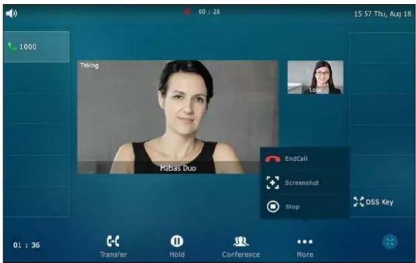
The status bar prompts "Call has been recorded on USB device successfully.".

- When there is only a call on the phone, tap the More soft key and then tap the EndCall soft key.
The LCD screen prompts "Call has been recorded on USB device successfully", the recording icon and recording duration disappear, and the phone returns to the idle screen.

The recording will be stored as a new file on the USB flash drive when the phone starts recording again.
Conference Recording
You can record conference calls in the same way as other calls with the following exceptions:
- All conference participants are recorded while recording. If one of the participants taps the Hold soft key, only that participant is recorded. When a conference call is placed on hold, recording of the conference is paused. You can place or answer other calls, which will be recorded in the same file. When the conference call is resumed, recording of the conference resumes.
- All conference participants are recorded while recording. If one of the participants presses 📋, only that participant is not recorded.
Recorded Calls Playback
If you insert a USB flash drive into the USB port on your phone, you can play back recorded calls on your phone.
You can also browse and delete the recorded files on the USB flash drive.
Note
Playback can occur on either the phone itself or on a computer using an application capable of playing *.mkv and *.aac files.
To browse the recorded audio-only files via phone user interface:
- Tap ->USB->Browse Audio.
The touch screen shows all recorded audio files in the Browse Audio list. The filename
consists of the recording time & date, the other party's number/IP address/name (or the first person's number/IP address/name you called).
-
Drag to scroll through the recorded files if required.
-
Tap the desired audio or ▶ to play.
The touch screen shows the recording duration and the size of the recorded file.

During the recording playback, you can do the following:
- Tap Ⓐ to pause the playback. Then ▶ appears on the touch screen. To continue the playback, tap ▶.
- Drag the slider to skip forward the playback or rewind the playback.
- Press - + to adjust the volume of the speakerphone.
- Tap ☐ to stop the playback.
To browse the recorded video files via phone user interface:
- Tap ->USB->Browse Video.
The touch screen shows all recorded video files in the Browse Video list. The filename consists of the recording time & date, the other party's number/IP address/name (or the first person's number/IP address/name you called).
-
Drag to scroll through the recorded files if required.
-
Tap the desired video or ▶ to play the video.
The touch screen shows the recording duration of the recorded file.

During the recording playback, you can do the following:
- Tap ⏻ to pause the playback. Then ▶ appears on the touch screen. To continue the playback, tap ▶.
- Drag the slider to skip forward the playback or rewind the playback.
- Press - + to adjust the volume of the speakerphone.
- Tap ☐ to stop the playback. The phone returns to the Browse Video screen.
If you are playing back a recorded call and an incoming call arrives on your phone, the playback pauses and the phone rings.
To delete a recorded file:
-
Tap ->USB.
-
Do one of the following:
- Tap Browse Audio.
Tap 📄 after the audio recording you want to delete. (Drag to scroll through the recorded audio files if required.)
The phone prompts "Delete this audio?".
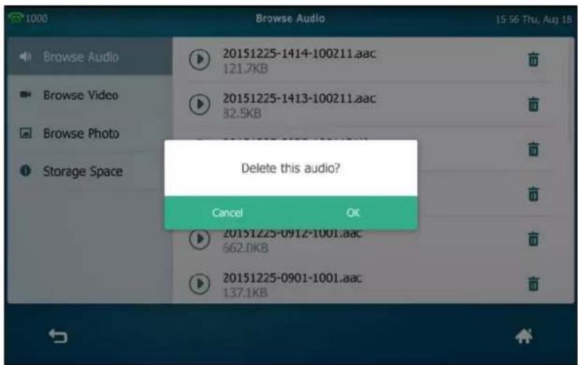
- Tap Browse Video.
Tap 📄 after the video recording you want to delete. (Drag to scroll through the recorded video files if required.)
The phone prompts "Delete this video?".
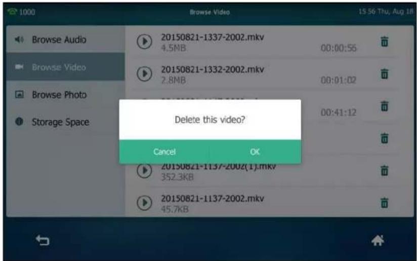
3. Tap OK to accept the change or Cancel to cancel.
Storage Space
You can check the storage space of the USB flash drive on the IP phone. And if you want to record active call or conference using a USB flash drive, there must be enough free space (greater than 2 minutes) on the USB flash drive.
To check the storage space of the USB flash drive via phone user interface:
1. Tap ->USB->Storage Space.
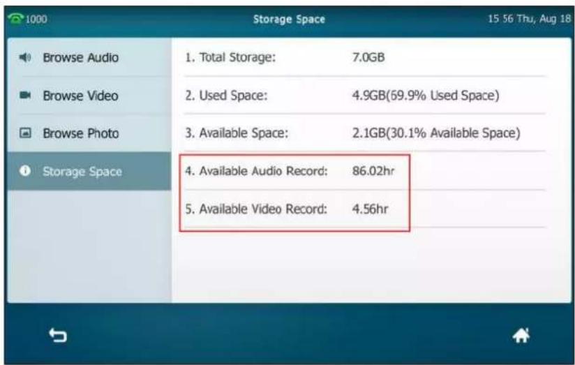
Call Recording Using a Record Key
You can record calls by tapping a record key on the phone. The SIP VP-T49G IP phone supports record and URL record.
Two ways of call recording:
- Record: The phone sends a SIP INFO message containing a specific header "Record: on/off" to trigger a recording.
- URL Record: The phone sends an HTTP URL request to trigger a recording. Contact your system administrator for the predefined URL.
Note
If you record a call using a USB flash drive, the recorded file will be stored in the USB flash drive. For more information, refer to Call and Conference Recording Using a USB Flash Drive on page 238.
Before recording any call, especially those involving PSTN, it is necessary to know about the rules and restrictions of any governing call-recording in the place you are in. It is also very important to have the consent of the person you are calling before recording the conversation.
Call recording is not available on all servers. Contact your system administrator for more information.
To configure a record key via phone user interface:
- Tap ->Features->DSS Keys.
- Tap the desired line key.
- Tap the Type field.
-
Tap Key Event in the pop-up dialog box.
-
Tap the Key Type field.
- Tap Record in the pop-up dialog box.
- (Optional.) Enter the string that will appear on the touch screen in the Label field.
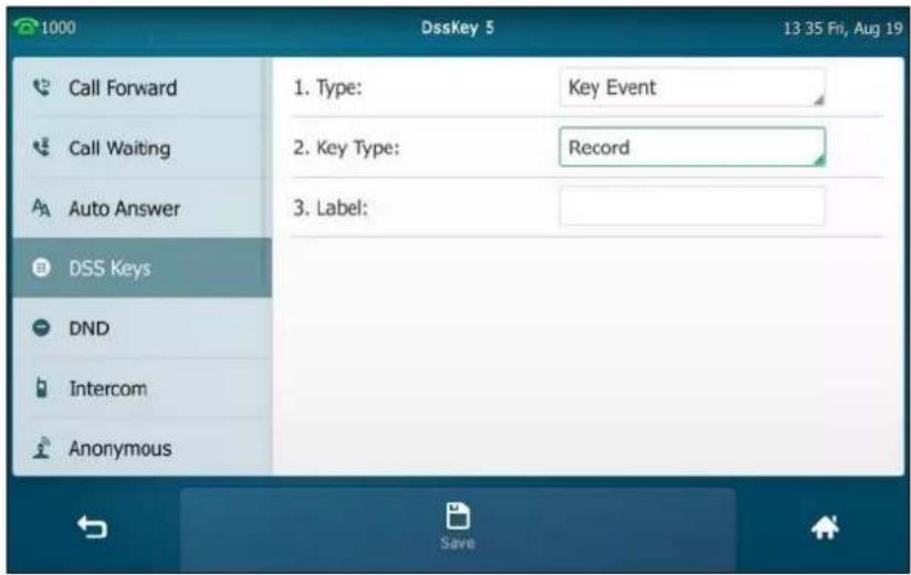
- Tap the Save soft key to accept the change or ↩ to cancel.
To configure a URL record key via phone user interface:
- Tap ->Features->DSS Keys.
- Tap the desired line key.
- Tap the Type field.
- Tap URL Record in the pop-up dialog box.
- (Optional.) Enter the string that will appear on the touch screen in the Label field.
- Enter the URL (e.g., http://10.1.2.224/phonerecording.cgi) in the URL Record field.

- Tap the Save soft key to accept the change or ↩ to cancel.
Record and URL record keys are configurable via web user interface at the path DSSKey->Line
Key.
The Record and URL Record keys control the recording function, and are available:
- During an active call
- When calls are on hold or muted
• During a blind or attended transfer
• During a conference call
The Record and URL Record keys are not available when:
- There are no connected calls on your phone
- You place a new call
To record a call:
- Tap the Record key or URL Record key during a call.
If the recording starts successfully, the recording icon will appear at the bottom right corner of the contact avatar and the icon indicators of the Record key or URL Record key changes to 🔒.
- Tap the Record key or URL Record key again to stop recording.
The recording icon disappears from the bottom right corner of the contact avatar and the icon indicators of the Record key or URL Record key changes to 📄.
Recording status indications you need to know:
| Circumstance | Icons on the touch screen |
| A recording is started | appears on the touch screen |
| A recording cannot be started | appears for 1 second |
| A recording cannot be stopped | appears for 1 second, then goes back |
| The recording box is full | appears for 1 second |
| The call cannot be recorded | appears for 1 second |
You can listen to the recordings stored on your server system. For example, you can dial an access code to listen to the recordings.
Note
The way in which you listen to the recordings may be different depending on the server. Contact your system administrator for more information.
Hot Desking
Hot desking originates from the definition of being the temporary physical occupant of a work station or surface by a particular employee. A primary motivation for hot desking is cost
reduction. This feature is regularly used in places where not all the employees are in the office at the same time, or not in the office for very long, which means that actual personal offices would be often vacant, consuming valuable space and resources.
You can use hot desking on the SIP VP-T49G IP phone to log out of existing accounts and then log into a new account. As a result, many users can share the phone resource at different times. To use this feature, you need to configure a hot desking key in advance.
Note
Hot desking is not available on all servers. Contact your system administrator for more information.
To configure a hot desking key via phone user interface:
- Tap ->Features->DSS Keys.
- Tap the desired line key.
- Tap the Type field.
- Tap Key Event in the pop-up dialog box.
- Tap the Key Type field.
- Tap Hot Desking in the pop-up dialog box.
- (Optional.) Enter the string that will appear on the touch screen in the Label field.

- Tap the Save soft key to accept the change or ↩ to cancel.
Hot desking key is configurable via web user interface at the path DSSKey->Line Key.
To use hot desking:
- Tap the hot desking key when the phone is idle.
The touch screen prompts the following warning:

- Tap OK.
Registration configurations of all accounts on the phone will be cleared immediately.
The login wizard will be displayed as below:
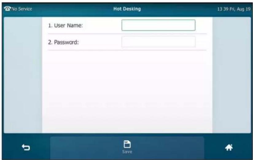
- Enter the login information in each field.
- Tap the Save soft key to login or ↩ to cancel.
Intercom
Intercom is a useful feature in an office environment to quickly connect with the operator or the secretary. You can tap the intercom key to automatically connect with a preconfigured target extension for outgoing intercom calls, and the target extension will automatically answer incoming intercom calls by default.
Note Intercom is not available on all servers. Contact your system administrator for more information.
Outgoing Intercom Calls
To configure an intercom key via phone user interface:
- Tap ->Features->DSS Keys.
- Tap the desired line key.
- Tap the Type field.
- Tap Intercom in the pop-up dialog box.
- Tap the Account ID field.
- Tap the desired line in the pop-up dialog box.
- (Optional.) Enter the string that will appear on the touch screen in the Label field.
- Enter the target extension number in the Value field.
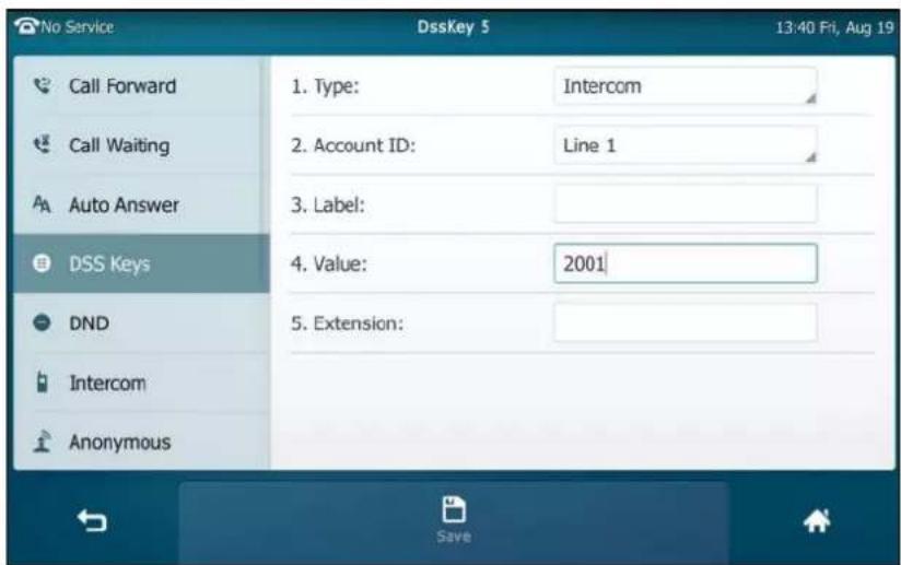
- Tap the Save soft key to accept the change or ↩ to cancel.
Intercom key is configurable via web user interface at the path DSSKey->Line Key.
Incoming Intercom Calls
The SIP VP-T49G IP phone supports automatically answering an incoming intercom call by default. The phone automatically plays a warning tone when it receives an incoming intercom call. In addition, you can enable the phone to mute the microphone when it automatically answers an incoming intercom call. You can also enable the phone to automatically answer an incoming intercom call while there is already an active call on the phone. The active call is then placed on hold.
Intercom features you need to know:
| Intercom Feature | Description |
| Accept Intercom | Enable or disable the IP phone to automatically answer an incoming intercom call. |
| Intercom Mute | Enable or disable the IP phone's microphone for intercom calls. |
| Intercom Tone | Enable or disable the IP phone to play a warning tone when it receives an incoming intercom call. |
| Intercom Barge | Enable or disable the IP phone to automatically answer an incoming intercom call while there is already an active call on the phone. |
Accept Intercom
You can enable or disable the phone to automatically answer an incoming intercom call. If Accept Intercom is enabled, the phone will automatically answer an incoming intercom call. If Accept Intercom is disabled, the phone will reject incoming intercom calls and send a busy message to the caller. Accept Intercom is enabled by default.
Note
Your administrator can set a period of delay time before the phone automatically answers intercom calls. Contact your system administrator for more information.
Intercom Mute
You can mute or un-mute the phone's microphone for intercom calls automatically. If Intercom Mute is enabled, the microphone will be muted for intercom calls. If Intercom Mute is disabled, the microphone will work for intercom calls. Intercom Mute is disabled by default.
Intercom Tone
You can enable or disable the phone to play a warning tone when receiving an intercom call. If Intercom Tone is enabled, the phone will play a warning tone before answering the intercom call. If Intercom Tone is disabled, the phone will automatically answer the intercom call without warning. Intercom Tone is enabled by default.
Intercom Barge
You can enable or disable the phone to automatically answer an incoming intercom call while there is already an active call on the phone. If Intercom Barge is enabled, the phone will automatically answer the intercom call and place the active call on hold. If Intercom Barge is disabled, the phone will handle an incoming intercom call like a waiting call. Intercom Barge is disabled by default.
Note
To enable the phone to receive a new incoming call when it has an active call, make sure that call waiting feature is enabled on the phone in advance. For more information, refer to Call Waiting on page 211.
To configure intercom features via phone user interface:
-
Tap ->Features->Intercom.
-
Make the desired changes.

- Tap the Save soft key to accept the change or ↩ to cancel.
These specific parameters are configurable via web user interface at the path Features->Intercom.
Using Intercom
To place an intercom call when the target phone is idle:
- Tap the intercom key when the phone is idle.
The called destination plays a warning tone and automatically answers the call in the hands-free (speakerphone) mode by default.
- To end the intercom call, tap the intercom key again or the EndCall soft key.
Multicast Paging
You can use multicast paging to quickly and easily broadcast time sensitive announcements out to people who are listening to a specific multicast group. You can configure a multicast paging key or a paging list key on the phone, which allows you to send a Real Time Transport Protocol (RTP) stream to the pre-configured multicast address(es) without involving SIP signaling. You can configure the phone to receive an RTP stream from pre-configured multicast listening address(es) without involving SIP signaling. You can specify up to 10 multicast listening addresses.
Sending RTP Stream
To configure a multicast paging key via phone user interface:
- Tap ->Features->DSS Keys.
- Tap the desired line key.
- Tap the Type field.
- Tap Key Event in the pop-up dialog box.
- Tap the Key Type field.
- Tap Multicast Paging in the pop-up dialog box.
- (Optional.) Enter the string that will appear on the touch screen in the Label field.
- Enter the multicast IP address and port number (e.g., 224.5.6.20:10008) in the Value field. The valid multicast IP addresses range from 224.0.0.0 to 239.255.255.255.
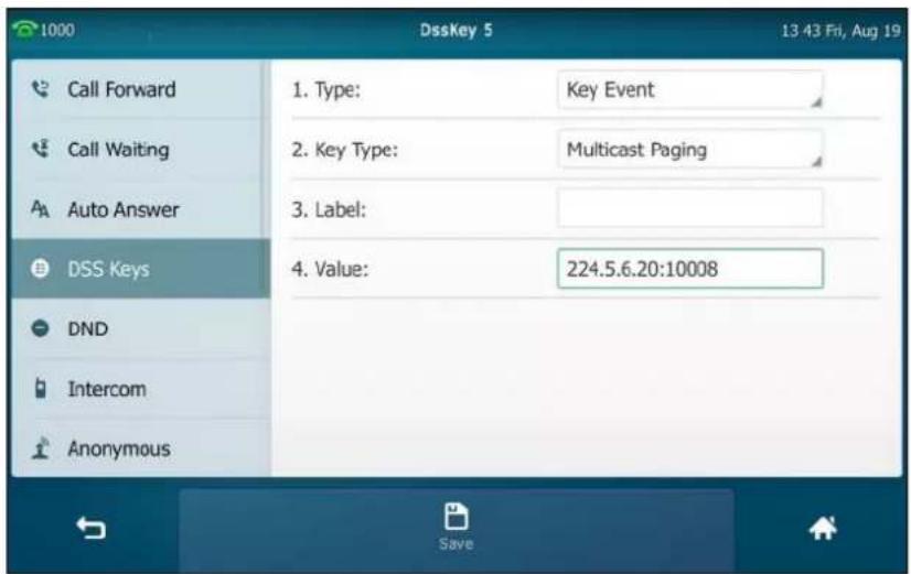
- Tap the Save soft key to accept the change or ↩ to cancel.
Multicast paging key is configurable via web user interface at the path DSSKey->Line Key.
To configure a paging list key via phone user interface:
-
Tap ->Features->DSS Keys.
-
Tap the desired line key.
- Tap the Type field.
- Tap Key Event in the pop-up dialog box.
- Tap the Key Type field.
- Tap Paging List in the pop-up dialog box.
- (Optional.) Enter the string that will appear on the touch screen in the Label field.
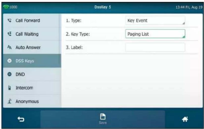
- Tap the Save soft key to accept the change or ↩ to cancel.
Paging list key is configurable via web user interface at the path DSSKey->Line Key.
To configure paging list via phone user interface:
- Tap the paging list key when the phone is idle.
- Tap a desired paging group.
The default tag is Empty if it is not configured before.

3. Tap the Edit soft key.

- Enter the multicast IP address and port number (e.g., 224.5.6.20:10008) in the Address field.
The valid multicast IP addresses range from 224.0.0.0 to 239.255.255.255.
- Enter the paging group name in the Label field.
- Tap the Save soft key to accept the change.
- Repeat steps 2 to 6, you can add more paging groups.
Paging list is configurable via web user interface at the path Directory->Multicast IP.
To delete paging group via phone user interface:
- Tap the paging list key when the phone is idle.
- Tap a desired paging group.
- Tap the Delete soft key.

- Tap OK to accept the change or Cancel to cancel.
If you want to delete all paging groups, you can tap the Delete All soft key.
You can also configure the phone to use a default codec for sending multicast RTP stream via web user interface.
To configure a default codec for multicast paging via web user interface:
-
Click on Features->General Information.
-
Select the desired codec from the pull-down list of Multicast Codec.
The default codec is G722.

- Click Confirm to accept the change.
Note
If G722 codec is used for multicast paging, the touch screen will display the icon to indicate that it is providing high definition voice.
Default codec for multicast paging is configurable via web user interface only.
Receiving RTP Stream
You can configure the phone to receive a Real Time Transport Protocol (RTP) stream from the pre-configured multicast address(es) without involving SIP signaling. You can specify up to 10 multicast addresses that the phone listens to on the network.
How the phone handles incoming multicast paging calls depends on Paging Barge and Paging Priority Active parameters configured via web user interface.
Paging Barge
The paging barge parameter defines the priority of the voice call in progress. If the priority of an incoming multicast paging call is lower than that of the active call, it will be ignored automatically. If Disabled is selected from the pull-down list of Paging Barge, the voice call in progress will take precedence over all incoming multicast paging calls. Valid values in the Paging Barge field:
• 1 to 10: Define the priority of the active call, 1 with the highest priority, 10 with the lowest.
- Disabled: The voice call in progress will take precedence over all incoming paging calls.
Paging Priority Active
The paging priority active parameter decides how the phone handles incoming multicast paging calls when there is already a multicast paging call on the phone. If enabled, the phone will ignore incoming multicast paging calls with lower priorities, otherwise, the phone will answer incoming multicast paging calls automatically and place the previous multicast paging call on hold. If disabled, the phone will automatically ignore all incoming multicast paging calls.
To configure multicast listening addresses via web user interface:
-
Click on Directory->Multicast IP.
-
Select the desired value from the pull-down list of Paging Barge.
-
Select the desired value from the pull-down list of Paging Priority Active.
-
Enter the multicast IP address(es) and port number (e.g., 224.5.6.20:10008) which the phone listens to for incoming RTP multicast in the Listening Address field.
-
Enter the label in the Label field.
Label will appear on the touch screen when receiving the multicast RTP stream.

- Click Confirm to accept the change.
Note
The priorities of listening addresses are predefined: 1 with the highest priority, 10 with the lowest. Multicast listening addresses are configurable via web user interface only.
Using Multicast Paging
To send RTP stream via a multicast paging key when the receiver's phone is idle:
- Tap the multicast paging key when the phone is idle.
The phone sends RTP to a preconfigured multicast address (IP: Port).
Both the sender's and receiver's phones play a warning tone and the receiver automatically answers the multicast RTP session in the hands-free (speakerphone) mode.
The multicast paging key icon indicator will become and solid.
The following figure shows a multicast RTP session on the phone:

- Your can do the following:
- Tap the Hold soft key to place the current multicast RTP session on hold.
The sender's phone places the multicast RTP session on hold and receiver's phone releases the session.
To resume the held multicast RTP session, tap the Resume soft key.
The multicast RTP session is established again.
- Tap the EndCall soft key to cancel the multicast RTP session.
Note
Multicast RTP is one way only from the sender to the multicast address(es) (receiver). For outgoing RTP multicasts, all other existing calls on the phone will be placed on hold.
To send RTP stream via a paging key list when the receiver's phone is idle:
-
Tap paging list key when the phone is idle.
-
Tap the desired paging group.

-
Tap the Paging soft key to send RTP.
-
Your can do the following:
- Tap the Hold soft key to place the current multicast RTP session on hold.
The sender's phone places the multicast RTP session on hold and receiver's phone releases the session.
To resume the held multicast RTP session, tap the Resume soft key.
The multicast RTP session is established again.
- Tap the EndCall soft key to cancel the multicast RTP session.
Music on Hold
Music on hold (MoH) is the business practice of playing recorded music to fill the silence that would be heard by the party placed on hold. To use this feature, you should specify a SIP URI pointing to a Music on Hold Server account. When a call is placed on hold, the phone will send a SIP INVITE message to the Music on Hold Server account. The Music on Hold Server account automatically answers the SIP INVITE messages and immediately plays audio from some source located anywhere (LAN, Internet) to the held party. Contact your system administrator for the SIP URI.
To configure music on hold server via web user interface:
-
Click on Account->Advanced.
-
Select the desired account from the pull-down list of Account.
-
Enter the SIP URI (e.g., sip:moh@sip.com) in the Music Server URI field.
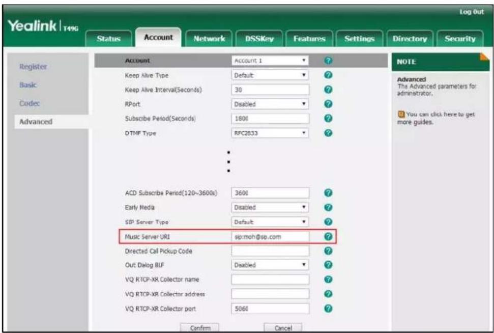
- Click Confirm to accept the change.
When you place a call on hold, music will be played to the held party.
Note
For this feature to function, all involved parties cannot use encrypted RTP (SRTP).
Music on hold server is configurable via web user interface only.
Shared Call Appearance (SCA)
You can use SCA feature to share an extension which can be registered on two or more IP phones at the same time. The shared line is indicated by a different line icon.
In the following figure, the first line is shared and the second line is private:

If two phones share a line, an incoming call to this extension will cause both phones to ring
simultaneously. The incoming call can be answered on either phone but not both.
This feature is very useful in the boss and secretary scenario. For example, the secretary can share the boss's extension on her phone. When there is an incoming call to the extension of the boss, both the phones of the boss and the secretary will ring simultaneously. Either the boss or the secretary can answer the call. Calls on the shared line can be placed on hold, barged in or retrieved from another shared phone.
Configuring SCA Feature on the IP Phone
You can configure a primary account on the IP phone and other alternate accounts on the other IP phones. In a SCA Hybrid Key System scenario, you can automatically assign multiple DSS keys with Line type for a registered shared line on the phone (If auto linekeys feature is enabled). For example, party A, party B share the account 4603, phone A registers the primary account 4603 and assigns line key 1 and line key 2 for the account 4603, phone B registers the alternate account 4603_1 and assigns line key 1 and line key 2 for the account 4603_1, phone C registers the account 4604.
![graph TD Server --> PhoneA["Phone A (line 1 and line 2):4603"] Server --> PhoneB["Phone B (line 1 and line 2):4603_1"] Server --> PhoneC["Phone C: 4604"] PhoneA --> PartyA PhoneB --> PartyB PhoneC --> PartyC](/content/2026/07/1418761/images/197e2c2f6940f25ba74c50b42741bda70b61d4c20ee330ec6eb845e582a49bc3.jpg)
To configure the auto linekeys feature via web user interface:
- Click on Features->General Information.
- Select Enabled from the pull-down list of Auto LineKeys.
If Auto LineKeys is enabled, you can automatically assign multiple DSS keys with Line type for a registered shared line on the phone.

- Click Confirm to accept the change.
To configure the shared line settings and the number of line key on phone A via web user interface:
- Register the primary account 4603.

- Click on Advanced, and then select Share Call Appearance from the pull-down list of Shared Line.
- Enter the desired number in the Number of line key field. This field appears only if Auto Linekeys feature is enabled.
The default value is 1. In this example, the value is set to 2.

- Click Confirm to accept the change.
The phone A will automatically configure the line keys from the first unused DSS key, according to the configured number in the Number of line key field.
To configure the shared line settings and the number of line key on phone B via web user interface:
- Register the alternate account 4603_1.
(Enter the primary account 4603 in the Register Name field.)

- Click on Advanced, and then select Shared Call Appearance from the pull-down list of Shared Line.
- Enter the desired number in the Number of line key field.
This field appears only if Auto Linekeys feature is enabled.
The default value is 1. In this example, the value is set to 2.

- Click Confirm to accept the change.
The phone B will automatically configure the line keys from the first unused DSS key, according to the configured number in the Number of line key field.
Configuring Private Hold Soft Key or Private Hold Key
Public hold allows any shared line to retrieve the held call. Private hold only allows the hold party to retrieve the held call. For example, you can retrieve the held call on either phone A or phone B when you place a call on public hold; you can retrieve the held call only on phone A when you place a call on private hold on phone A. By default, the private hold soft key isn't displayed on the touch screen. You need to configure either the private hold soft key or a private hold key before you place the call on private hold.
To configure the private hold soft key via web user interface:
- Click on Settings->Softkey Layout.
- Select Enabled from the pull-down list of Custom Softkey.
- Select On Talk from the pull-down list of Call States.
- Select Private Hold from the Unselected Softkeys column and then click □.
The Private Hold appears in the Selected Softkeys column.

- Click Confirm to accept the change.
Note
Configuring the private hold soft key may affect the softkey layout in the Talking state. Contact your administrator for more information.
To configure a private hold key via phone user interface:
- Tap ->Features->DSS Keys.
- Tap the desired line key.
- Tap the Type field.
- Tap Key Event in the pop-up dialog box.
- Tap the Key Type field.
- Tap Private Hold in the pop-up dialog box.
- (Optional.) Enter the string that will appear on the touch screen in the Label field.
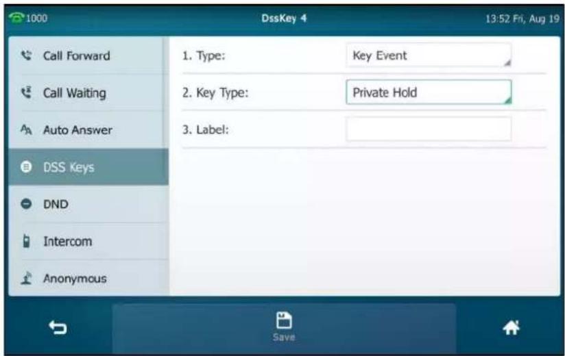
- Tap the Save soft key to accept the change or ↩ to cancel.
Configuring Call Pull Feature
Call pull feature allows users to retrieve an existing call from another shared phone that is in active or public hold status.
To configure the call pull feature access code via web user interface:
- Click on Account->Advanced.
- Select the desired account from the pull-down list of Account.
- Enter the call pull feature access code (e.g., *11) in the Call Pull Feature Access Code field.

- Click Confirm to accept the change.
The phone will dial out "*11" automatically when you tap the CallPull soft key.
Using SCA Feature on the IP Phone
This section provides you with detailed information on using the SIP VP-T49G IP phone in a SCA Hybrid Key System scenario. In a SCA Hybrid Key System scenario, the status of the line key icon which associates with a shared line will change. For more information on line key icon indicator, refer to Icon Instructions on page 20. You can do the following using the IP phone in a SCA Hybrid Key System scenario:
- Placing calls
- Answering calls
- Placing a call on hold
- Retrieving a held call
- Barging in an active call
- Call Pull
Placing Calls
You can have one call or multiple calls on the shared line.
To place a call on the shared line:
Do one of following:
- Enter the desired number.
Press #SEND , or tap Send.
The phone will dial the entered number using the first line key.
- Tap the line key when the phone is idle to enter the dialing screen.
Enter the desired number and then press #SEND , or tap Send.
The phone will dial the entered number using the selected line key.
To place multiple calls on the shared line:
You can have more than one call on the shared line. To place a new call when there is an active call on the line key 1 of phone A, do one of the following on phone A:
- Press 📄 or tap the Hold soft key. The original call is placed on hold.
Tap the NewCall soft key to enter the dialing screen.
Enter the desired number.
Press #send , or tap Send.
Phone A will dial the entered number using the line key 2 automatically.
- Tap the line key. The original call is placed on hold.
Enter the desired number.
Press #send, or tap Send.
Phone A will dial the entered number using the selected line key.
Answering Calls
You can have one call or multiple calls on the shared line. Incoming calls will be distributed evenly among the available line keys.
To answer a call on the shared line:
When an incoming call arrives on the shared line, the phone A and phone B will ring simultaneously, and the icon indicators of the line key 1 on both phone A and phone B will become 📄 and flashing. You can answer the incoming call on either phone A or phone B but not both.
Do one of the following on phone A or phone B:
- Tap the line key 1, or tap the Answer soft key on phone A.
The icon indicators of the line key 1 on phone A and phone B will become "and solid."
- Tap the line key 1, or tap the Answer soft key on phone B.
The icon indicators of the line key 1 on phone A and phone B will become "and solid."
To answer multiple calls on the shared line:
An incoming call arrives on the shared line when there is an active call on phone A's line key 1. The icon indicators of the line key 2 on both phone A and phone B will become 📄 and flashing. You can answer the incoming call on either phone A or phone B. The touch screen of phone A displays the information of the incoming call (e.g., "Incoming call 4604 Yealink").
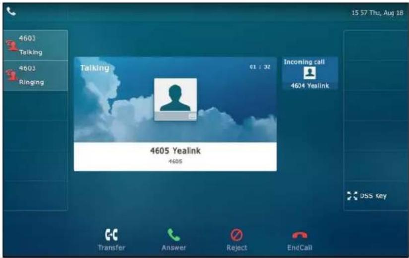
Note
Make sure call waiting feature is enabled on phone A. For more information, refer to Call Waiting on page 211.
Do one of the following on phone A:
- Tap the line key 2. Phone B stops ringing.
- Tap the Answer soft key. Phone B stops ringing.
- Tap the incoming call prompt box.
Tap the Answer soft key. Phone B stops ringing.
The incoming call is answered and the original call is placed on hold. The icon indicators of the line key 1 on phone A and phone B will become 🎩 and solid indicating that there is the held call on the line key 1. The icon indicators of the line key 2 on phone A and phone B will become

and solid indicating that there is an active call on the line key 2.
You can also answer the call on phone B. Do one of the following on phone B:
- Tap the line key 2. Phone A stops ringing.
- Tap the Answer soft key. Phone A stops ringing.
The icon indicators of the line key 2 on phone A and phone B will become 🎨 and solid indicating that there is an active call on the line key 2. Meanwhile, the icon indicators of the line key 1 phone A and phone B will become 🔍 and solid indicating that there is the held call on the line key 1.
Note
If the number of incoming calls is greater than the configured line keys, the line keys will be used by sequence circulation.
Placing a Call on Hold
To place a call on public hold:
- Press 📁 or tap the Hold soft key on phone A when party A and party C are talking.

The icon indicators of line key 1 on phone A and phone B will become
To place a call on private hold:
- Press the PriHold soft key or private hold key on phone A when there is an active call on the shared line (You may need to press the More soft key to see the PriHold soft key).

The icon indicators of line key 1 on phone A will become 📁 when the shared line call is placed on private hold.
The icon indicators of line key 1 on phone B will become 📁 when the shared line call is placed on private hold.
Retrieving a Held Call
To retrieve a call placed on public hold:
You can retrieve the public held call on either phone A or phone B.
To retrieve the call on phone A:
- Tap 📋, press 🎯 or tap the Resume soft key.
The conversation between phone A and phone C is retrieved.
To retrieve the call on phone B:
Do one of the following:
- Tap
- Long tap the desired line key. The Cancel, CallPull, NewCall and Retrieve soft keys appear on the touch screen.
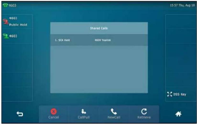
Tap the Retrieve soft key to retrieve the call.
The conversation is established between phone B and phone C, phone A disconnects the call.
And the line key icon on phone A and phone B will become
To retrieve a call placed on private hold:
The private held call can be only retrieved by the hold party (party A).
Do the following:
- Tap 📞, press 📞 or tap the Resume soft key on phone A.
The conversation between phone A and phone C is retrieved.
Barging In an Active Call
To interrupt the active call on the shared line:
If phone A has only one active call, do the following:
- Long tap the desired line key on phone B.
The Cancel, CallPull, NewCall and Barge In soft keys appear on the touch screen of phone B.

- Tap the Barge In soft key to interrupt the active call of phone A.
Party B will set up a conference call with the other parties in the active call.
- Press 📄, tap the Hold soft key or the EndCall soft key.
- If any party in the conference call presses 📁 or taps the Hold soft key, two-way voice can be heard between the remaining parties.
- If party A or party B taps the EndCall soft key, the remaining parties are still connected. If the other party (not the shared line party) taps the EndCall soft key, the conference call is ended.
You can also tap the line key with the solid red icon indicator on phone B to set up a conference call with the other parties in the active call.
If phone A has more than one call, do the following:
- Long tap the desired line key on phone B.
The list of calls appears on the touch screen of phone B.

- Tap the item to select the active call.
The Cancel, CallPull, NewCall and Barge In soft keys appear when the active call is highlighted.

- Tap the Barge In soft key to interrupt the active call of phone A.
Party B may hear a warning tone and then set up a conference call with the other parties of the active call.
- Press 📁, tap the Hold soft key or the EndCall soft key.
- If any party in the conference call presses 📁, taps the Hold soft key, two-way voice can be heard between the remaining parties.
- If party A or party B taps the EndCall soft key, the remaining parties are still connected. If the other party (not the shared line party) taps the EndCall soft key, the conference call is ended.
Call Pull
Call pull feature allows users to retrieve an existing call from another shared phone that is in active or hold status. For example, when there is a call between phone A and phone C, you can use call pull feature on phone B to retrieve this call from phone A. Then the call is established between phone B and phone C.
To retrieve a call from another shared phone:
If there is an active call between phone A and phone C, do the following:
- Long tap the desired line key on phone B.
The Cancel, CallPull, NewCall and Barge In soft keys appear on the touch screen of phone B.
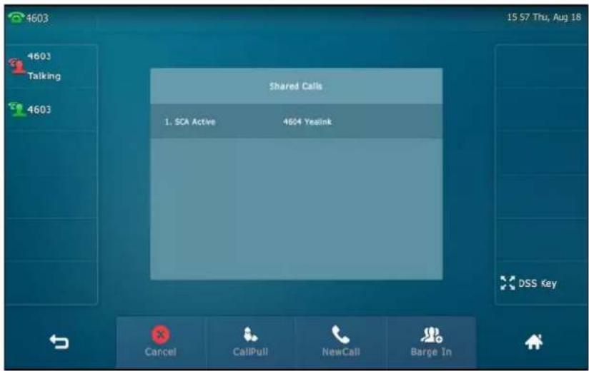
2. Tap the CallPull soft key.
The active call has been retrieved from the phone A successfully.
If there is a held call between phone A and phone C, do the following:
1. Long tap the desired line key on phone B.
The Cancel, CallPull, NewCall and Retrieve soft keys appear on the touch screen of phone B.

2. Tap the CallPull soft key.
The held call has been retrieved from the phone A successfully.
Messages
Short Message Service (SMS)
You can send and receive text messages using the SIP VP-T49G IP phone. New text messages can be indicated both acoustically and visually. When receiving a new text message, the phone will play a warning tone. The power indicator LED will slowly flash red, and the touch screen will prompt "n New Text Message(s)" ("n" indicates the number of unread text messages. e.g., 1 New Text Message(s)) and display an icon 📧.
Note
When the phone receives a text message, the text message prompt window will pop up by default, if you want to disable the feature, contact your system administrator for more information.

You can store text messages in your phone's Inbox, Sentbox, Outbox or Draftbox. Each of the boxes can store up to 100 text messages. If the number of the text messages in one box is more than 100, the phone will directly delete the oldest text message in the box.
Note
SMS is not available on all servers. Contact your system administrator for more information.
To read a text message:
1. Tap ->Message->Text Message->Inbox.

2. Tap the desired text message to read.
Note
If the phone prompts receiving new text messages, you can also tap the View soft key to read the new messages directly.
To send a text message:
- Tap ->Message->Text Message->New Text Message.
- Tap the From field.
- Tap the desired account in the pop-up dialog box.
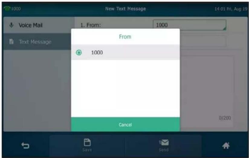
- Enter the number you want to send the message to in the To field.
![1000 New Text Message 14 02 Fri, Aug 19 Voice Mail 1. From: 1000 Text Message 2. To: 1038 ~ * - _ = + ( ) 4 5 6 < > [ ] { } | 7 8 9 abc ; : " \ / 0 .](/content/2026/07/1418761/images/3eec6b21fec8bc08cef0b5f03b1a4393ad0d89c9bf5cc506c93eb8caf0069aa4.jpg)
- Compose the new text message. You can tap &123 to change the input mode.

-
Tap to hide the onscreen keyboard.
-
Tap the Send soft key to send or ↩ to cancel.
You can also tap the Save soft key to save the text message to the draftbox.
Sending a text message is configurable via web user interface at the path Features->SMS.
To reply a text message:
-
Tap ->Message->Text Message->Inbox.
-
Select the desired message and tap the Reply soft key.
-
Compose the new text message. You can tap &123 to change the input mode.
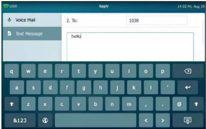
- Tap to hide the onscreen keyboard after completing the content.
- Check the From and To fields, and then tap the Send soft key.
To delete a text message:
- Tap ->Message->Text Message->Inbox (Sentbox, Outbox or Draftbox).
- Tap the desired message and then tap the Delete soft key.
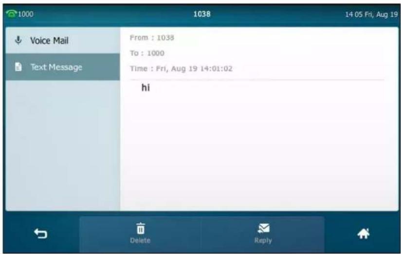
The touch screen prompts "Delete this message?".

- Tap OK to delete this message or Cancel to cancel.
You can also delete all text messages by tapping the Delete All soft key. For more information, refer to the above steps.
Note
You can also delete a specific message after retrieving by tapping the Delete soft key.
Video/Voice Mail
You can leave video/voice mails for someone else using the SIP VP-T49G IP phone. You can also access the video/voice mails that are stored in the voice mailbox. The usage of video mail is the same as that of voice mail, the following takes voice mail as an example.
Note
Video/voice mail is not available on all servers and differs from different servers. Contact your system administrator for more information.
When receiving a new voice mail, the phone will play a warning tone. The power indicator LED will slowly flash red, and the touch screen will prompt "n New Voice Mail(s)" ("n" indicates the number of unread voice mails, e.g., 5 New Voice Mail(s)) and display an icon 🔒.

If the voice mail pop-up message box disappears, it won't pop up again unless the user receives a new voice mail or the user re-registers the account that has unread voice mail(s).
Note
You can configure the phone not to display the pop-up prompt, contact your system administrator for more information.
The icon 🙏 on the status bar has a counter indicating the number of messages you haven't heard yet.
To leave a voice mail:
You can leave a voice mail for someone else when he/she is busy or inconvenient to answer the call. Follow the voice prompt from the system server to leave a voice mail, and then hang up.
To configure voice mail access codes via phone user interface:
-
Tap → Message→Set Voice Mail.
-
Enter the voice mail access code (e.g., *88) in the desired account field.
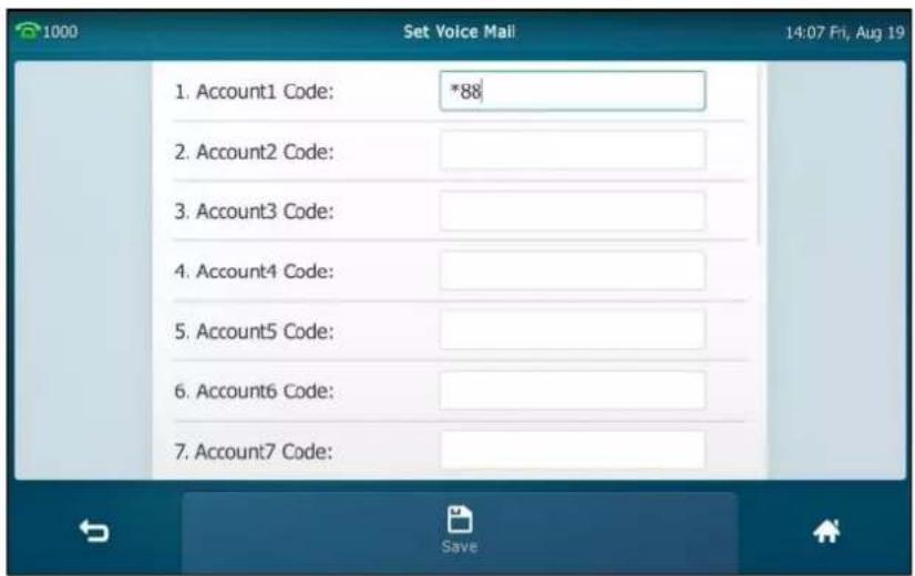
- Tap the Save soft key to accept the change or ↩ to cancel.
Note
Voice mail access codes must be predefined on the system server. Contact your system administrator for the more information.
To listen to voice mails:
- When the touch screen prompts that the phone receives a new voice mail, press 📞 or tap Connect to dial out the voice mail access code.
- Follow the voice prompt to listen to your voice mails.
Note
Before listening to voice mails, ensure that the voice mail access code has been configured.
To view the voice mail via phone user interface:
- Tap ->Message->View Voice Mail.
The touch screen displays the amount of new and old voice mails.
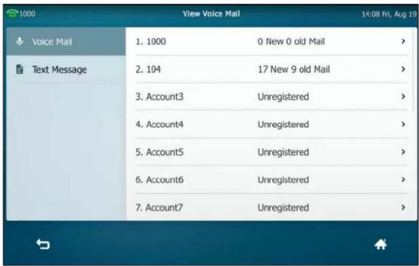
You can tap the account to listen to voice mails.
Message Waiting Indicator (MWI)
The SIP VP-T49G IP phone supports MWI when receiving a new voice mail. If someone leaves you a voice mail, you will receive a message waiting indicator. MWI will be indicated in three ways: a warning tone, an indicator message (including a voice mail icon) on the touch screen, and the power indicator LED slowly flashes red. This will be cleared when you retrieve all voice mails or delete them.
The MWI service is unsolicited for some servers, so the SIP VP-T49G IP phone only handles the MWI messages sent from the server. But for other servers, the MWI service is solicited, so the SIP VP-T49G IP phone must enable subscription for MWI.
Note
MWI service is not available on all servers. Contact your system administrator for more information.
The MWI subscription parameters you need to know:
| Options | Description |
| Subscribe for MWI | Enable or disable a subscription for MWI service. |
| MWI Subscription Period | Period of MWI subscription. The IP phone sends a refresh SUBSCRIBE request before initial subscription expires. |
| Subscribe MWI To Voice Mail | Enable or disable a subscription to the voice mail number for MWI service.To use this feature, you should also configure the voice mail number. |
Note
The phone will send SUBSCRIBE messages for MWI service to the account or the voice number MWI service depending on the server. Contact your system administrator for more information.
To configure subscribe for MWI via web user interface
- Click on Account->Advanced.
- Select the desired account from the pull-down list of Account.
- Select Enabled from the pull-down list of Subscribe for MWI.
- Enter the period time in the MWI Subscription Period(Seconds) field.

- Click Confirm to accept the change.
The IP phone will subscribe to the account number for MWI service by default.
To enable subscribe MWI to voice mail via web user interface:
- Click on Account->Advanced.
- Select the desired account from the pull-down list of Account.
-
Select Enabled from the pull-down list of Subscribe for MWI.
-
Select Enabled from the pull-down list of Subscribe MWI To Voice Mail.
- Enter the desired voice mail number in the Voice Mail field.
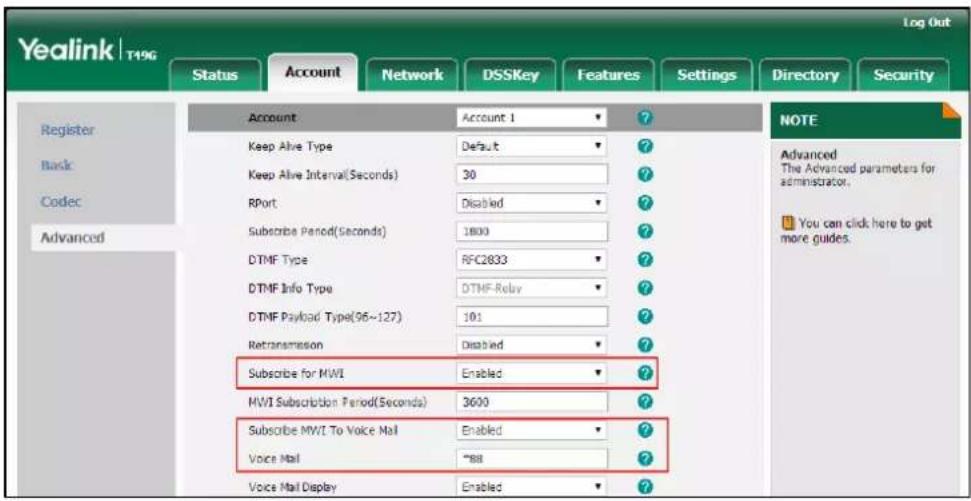
- Click Confirm to accept the change.
The IP phone will subscribe to the voice mail number for MWI service using Subscribe MWI To Voice Mail.
Note
MWI subscription is configurable via web user interface only.
Video Conferencing Features
Video Conferencing
You can enable video conferencing feature to be able to configure or use the following features:
- Setup Wizard
• Video Conference Platform
• H.323 Settings - SIP IP Call Settings
- Call Stats Key
• Videoconferencing Key
To enable the video conferencing feature via phone user interface:
- Tap -> Basic-> Video Setting.
- Tap the Video Conferencing Features field.
3. Tap Enabled in the pop-up dialog box.

4. Tap the Save soft key.
Video conferencing feature is configurable via web user interface at the path Settings->Video.
Setup Wizard
If you enable the video conferencing feature (refer to Video Conferencing) and there is no account registered on the phone (the account information is empty), the setup wizard will appear on the LCD screen after startup. You can use the setup wizard to register a Yealink Cloud/YMS/Custom/Zoom/Pexip/Mind/BlueJeans/StarLeaf account.
To configure the setup wizard:
1. Tap the desired platform.
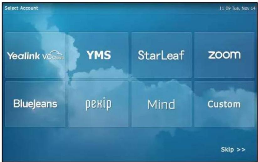
- Enter the desired value in the corresponding field.
- Tap the Log in soft key.
During the setup wizard, you can tap Skip>> to skip the setup wizard and go to the idle screen.
Video Conference Platform
The IP phone is compatible with Yealink VC Cloud Management Service/Yealink Meeting Server (YMS)/StarLeaf/Zoom/Pexip/BlueJeans/Mind platform. You can log into the desired platform, and use the corresponding features.
Yealink VC Cloud Management Service Platform
The Yealink VC Cloud Management Service is a value-added cloud-based service platform for Cloud endpoints. It offers significant convenience and cost-savings to integrators and business customers in terms of deployment, configuration and usage.
Logging into Yealink VC Cloud Management Service Platform
You can register a Yealink Cloud account to log into Yealink VC Cloud Management Service platform. There are two methods of registering a Yealink Cloud account:
• PIN code: This method uses the PIN code to register the Yealink Cloud account.
- Account: This method uses the username (Cloud number) and password to register the Yealink Cloud account.
You can obtain the Yealink Cloud account information from your Yealink Cloud enterprise administrator. You can register one Yealink Cloud account on up to five Cloud endpoints simultaneously.
The touch screen will have the following changes:
- The background color of four shortcut key is changed.
- The idle screen displays a Meet Now shortcut key. For more information, refer to Meet Now on page 299.
- The idle screen displays the daily latest conference schedule and the menu screen displays a Schedule menu. For more information, refer to Viewing Scheduled Conference Information on page 293.
- The notification center displays an Ongoing Conference tab. For more information, refer to Joining a Scheduled Conference from Notification Center on page 296.
Note
You can only register one Yealink Cloud account/YMS account. It means you cannot log into the Yealink Cloud or Yealink Meeting Server platform at the same time.
PIN Code
To log into Yealink VC Cloud Management Service platform using the PIN code:
- Tap ->Advanced (default password: admin) ->VC Account->Cloud Account.
- Tap the desired account.
- Tap the Type field.
-
Tap Yealink Cloud in the pop-up dialog box.
-
Tap the PIN Code radio box.
- Enter the PIN code in the Please input 9-digit pincode field.
- Enter the desired value in the Server field.

- Tap the Log in soft key.
Note
If you fail to register a Yealink Cloud account by using PIN code, you can re-enter the PIN code according to the pop-up prompt or contact your Yealink Cloud enterprise administrator.
The PIN code can be used only once.
Account
To log into Yealink VC Cloud Management Service platform using an account:
- Tap ->Advanced (default password: admin) ->Account.
- Tap the desired account.
- Tap the Type field.
- Tap Yealink Cloud in the pop-up dialog box.
- Tap the Account radio box.
-
Enter the desired value in User Name, Password and Server field respectively.
-
(Optional.) Tap the Remember the Password checkbox.
-
Tap the Log in soft key.
Yealink Cloud account is configurable via web user interface at the path Account->Cloud Account.
Note
If you fail to register a Yealink Cloud account by using an account, you can re-enter the account information according to the pop-up prompt or contact your Yealink Cloud enterprise administrator.
Using Yealink VC Cloud Management Service Platform
After logging into Yealink VC Cloud Management Service platform, you can:
- Sync the Yealink Cloud contact.
• Dial the other Yealink Cloud account to establish a conversation.
• Use the Yealink Cloud video conference feature.
Yealink Cloud Directory
If you log into the Yealink VC Cloud Management Service platform, Yealink Cloud contacts which are created by your Yealink Cloud enterprise administrator, appear in your IP phone.
There are three types of Yealink Cloud contact:
- Contact: The users with Yealink Cloud accounts. The Yealink Cloud enterprise administrator can create departments for users.
- Room system: The devices with Yealink Cloud accounts registered in the video meeting room.
- VMR: It is also called the Permanent VMR. The Yealink Cloud enterprise administrator can determine whether to synchronize the permanent VMR to the IP phone.
Note that only the Yealink Cloud enterprise administrator has the permission to add, edit and
delete Yealink Cloud contacts. Contact your Yealink Cloud enterprise administrator for more information.
You can place calls to or search for the Yealink Cloud contacts. For more information on the Yealink Cloud directory, please refer to Yealink VC Cloud Management Service Administrator Guide.
To place a call to a Yealink Cloud contact:
1. Tap ->Cloud Directory.
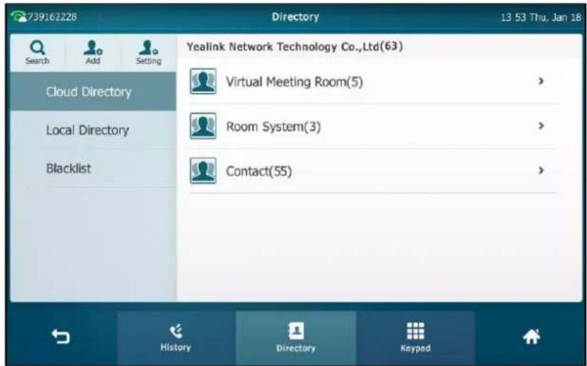
2. Tap the desired contact type, do one of the following:
- Tap the desired contact.
- Tap ⓘ after the desired contact.
Tap Send.
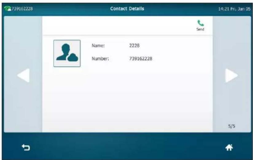
Dialing Yealink Cloud Accounts
If you want to place a call to a Yealink Cloud contact who is in the same Yealink Cloud directory
as you, you can enter the 9-digit Cloud number or the extension (the last four Cloud number) to place a call. If you want to place a call to a Yealink Cloud contact who is in different Yealink Cloud directory from you, you should enter the 9-digit Cloud number to place a call.
To dial a Yealink Cloud account:
- Pick up the handset, press the Speakerphone key or tap the line key.
- Enter the desired Yealink Cloud account number.
- Tap Send.
Yealink Cloud Video Conference
There are three types of Yealink Cloud video conference:
- Scheduled conference: You should schedule the conference using the Yealink VC Cloud Management Service or Microsoft Outlook software.
- Meet Now: You can initiate a meet now conference at any time, without a reservation.
- Permanent Virtual Meeting Room: The permanent VMR is created by your Yealink Cloud enterprise administrator. You can join the permanent VMR at any time without a reservation.
With the Yealink Cloud video conferencing feature, you can:
• View and join scheduled conferences.
- Initiate and join meet now conferences.
- Join the permanent VMR.
- Manage conferences.
Scheduled Conference
You can schedule a conference using the Yealink VC Cloud Management Service or Microsoft Outlook software. After you schedule the conference, the scheduled conference will be added to all invitees' IP phone. And invitee whose Yealink Cloud account is associated with an email address, will receive an email about how to join the conference.
For more information on how to schedule a conference, refer to Yealink VC Cloud Management Service Administrator Guide.
Viewing Scheduled Conference Information
If you register a Yealink Cloud account successfully, the idle screen will display your upcoming or ongoing conference schedules for today.
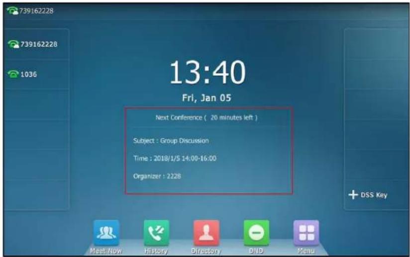
And there will be a Schedule menu on the menu screen. You can view all scheduled conference information in Schedule menu. The IP phone will not display the expired scheduled conference information. The scheduled conference information contains subject, conference ID, time, password, organizer and participants. If the conference organizer edits the conference content (e.g., time and participants) or cancel the conference via Yealink Meeting Server or Microsoft Outlook software after you have sent the invitation, the conference schedule will update in real time.
To view scheduled conference information in the Schedule menu:
-
Do one of the following:
-
Tap the Next Conference box on the idle screen.
- Tap ->Schedule.
The daily conference information will display as a list on the right of the touch screen.
- (Optional.) Tap a desired date on the calendar to view the schedule of selected day.
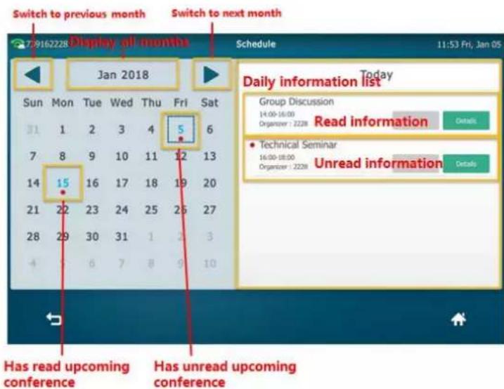
- Tap Detail to view the conference details.

Joining a Scheduled Conference
You can join the scheduled conference in following ways:
- Joining a scheduled conference from a conference reminder
- Joining a scheduled conference from notification center
• Joining a scheduled conference from the Schedule
• Dialing to join a scheduled conference
Joining a Scheduled Conference from a Conference Reminder
A pop-up reminder is displayed 5 minutes before the conference starts.

To join a conference from a conference reminder:
-
Do one of the following:
-
Tap Join to join the conference.
- Tap Details.
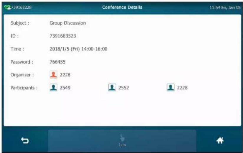
Tap the Join soft key to join the conference.
If you do not want to join the conference, you can tap Ignore to permanently remove the reminder from the screen and stop all future reminders for this schedule.
Note
If the IP phone is during a call, the touch screen will not pop up the reminder. In this case, if the scheduled conference is still ongoing when the call ends, the touch screen will pop up the reminder. If the scheduled conference has ended before the call ends, the touch screen will not pop up the reminder.
Joining a Scheduled Conference from Notification Center
If you register a Yealink Cloud account successfully, the notification center will display an Ongoing Conference tab.
By default, when the conference is about to take place in 5 minutes, the status bar displays the icon and the notification center displays the conference information. You can tap the desired conference notification to join the conference in advance. Or during the conference, you can tap the desired conference notification to join the conference.
Note
The icon 📂 on the status bar has a counter indicating the number of ongoing conferences. For example, 📂 indicates there are 3 ongoing conferences.
The Yealink Cloud enterprise administrator can configure the time for the participants to join the conference in advance. For more information, refer to your Yealink Cloud enterprise administrator.
To join a conference from notification center during the conference duration:
- Swipe down from the top of the screen to enter the notification center.

- Under the Ongoing Conference tab, tap the desired conference notification to join the conference.
Joining a Scheduled Conference from Schedule
By default, you can join a scheduled conference that is about to take place in 5 minutes or less.
Note
The Yealink Cloud enterprise administrator can configure when participants can join the scheduled conference. For more information, refer to your Yealink Cloud enterprise administrator.
To join a conference from Schedule:
1. Do one of the following:
- Tap the Next Conference box on the idle screen.
Tap ->Schedule.
The daily conference information will display as a list on the right of the touch screen.
2. Tap a desired date on the calendar to view the schedule of selected day.

3. Do one of the following:
- Tap Join to join the conference.
Tap Detail to view the conference details.

Tap the Join soft key to join the conference.
Dialing to Join a Scheduled Conference
If you schedule a conference or you are invited to join a scheduled conference, you can obtain the conference information in following ways:
- Invitee whose Yealink Cloud account is associated with an email address will receive an email, which includes the domain name, conference ID, conference password and the way of joining a scheduled conference.
- The IP phone displays conference information, which includes the conference ID and conference password. For more information, refer to Viewing Scheduled Conference Information on page 293.
- Contact the conference participants.
The IP phone will fail to join the conference in the following scenario:
• The conference is expired.
- You enter the wrong conference information.
- The current time is more than 5 minutes before the scheduled start time.
Note
The Yealink Cloud enterprise administrator can configure the time for the participants to join the conference in advance. For more information, refer to your Yealink Cloud enterprise administrator.
To dial into a conference:
-
Do one of the following:
-
If you register a Yealink Cloud account, dial the conference ID to join the conference. Obtain the conference information from your IP phone, your email or the other conference participants.
- If you do not register a Yealink Cloud account, dial the server address to join the conference.
Obtain the conference information from the other conference participants.
- To join from a SIP device, dial conference ID**conference password@server address to join the conference.
Obtain the conference information from the conference participants or your email address.
Meet Now
If you register a Yealink Cloud account successfully, the idle screen will display a Meet Now shortcut key.
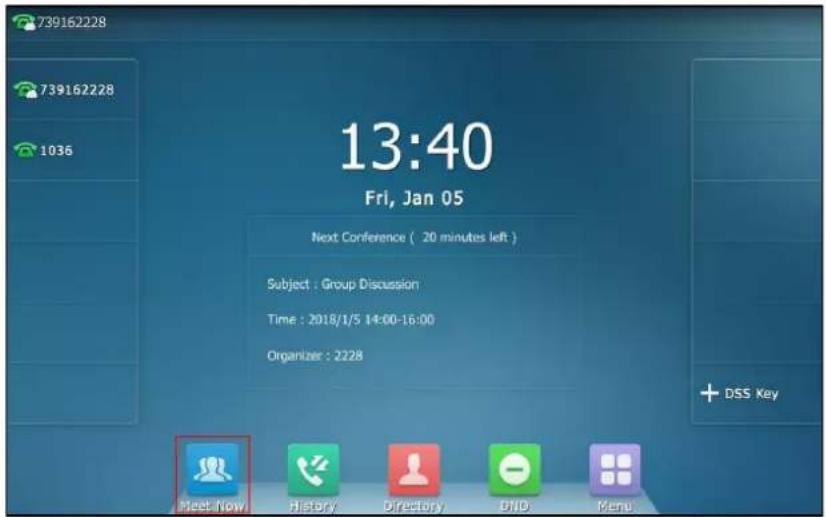
You can initiate a meet now conference by tapping 🏠 at any time.
Initiating a Meet Now Conference
To initiate a meet now conference:
1. Tap
The conference is initiated successfully.
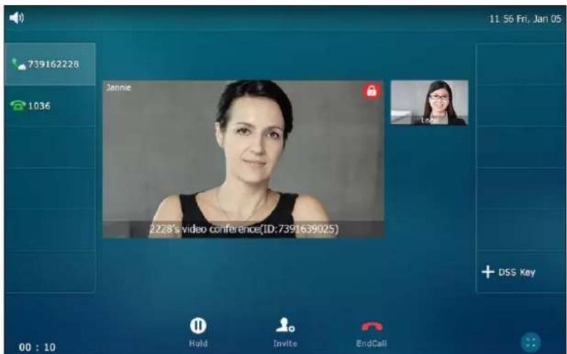
Joining a Meet Now Conference
In the ongoing meet now conference, you can dial to join the conference. And you can obtain the conference information from the participants of meet now conference.
To dial to join a meet now conference, do one of the following:
- If you register a Yealink Cloud account, you can dial the conference ID to join the conference.
- To join from a SIP device, dial conference ID**@server address to join the conference.
Permanent Virtual Meeting Room
Permanent VMR is a permanent virtual meeting room created by Yealink Cloud enterprise administrator. The conference ID of the permanent VMR is fixed, you can join the permanent VMR at any time.
You can join the permanent VMR in following ways:
- Joining a permanent VMR from Yealink Cloud directory
• Dialing to join a permanent VMR
Joining a Permanent VMR from Yealink Cloud Directory
You can search and check the permanent VMR information then place a call to the permanent VMR from Yealink Cloud directory.
Note
The Yealink Cloud enterprise administrator can determine whether to synchronize the permanent VMR to the IP phone. For more information, please refer to Yealink VC Cloud Management Service Administrator Guide.
To join a permanent VMR from enterprise directory:
1. Tap ->Cloud Directory->Virtual Meeting Room.

2. Do one of the following:
Tap the desired permanent VMR.
Tap ⓘ after the desired permanent VMR.
Tap Send to dial out the conference ID.
Dialing to Join a Permanent VMR
Do one of the following to dial to join a permanent VMR:
If you register a Yealink Cloud account, you can dial the conference ID to join the permanent VMR.
- For SIP devices, if you do not register a Yealink Cloud account and the permanent VMR requires no password, dial conference ID**@server address to join the permanent VMR.
- For SIP devices, if you do not register a Yealink Cloud account and the permanent VMR requires a password, dial conference ID**conference password@server address to join the permanent VMR.
Yealink Cloud Video Conference Management
Inviting Conference Participants
During the Yealink Cloud video conference, you can invite other Yealink Cloud account to join the conference.
Note
You are not allowed to invite other Yealink Cloud account to join the conference if you join the conference by dialing a URI.
To invite conference participants during the Yealink Cloud video conference:

1. Tap Invite.
2. Do one of the following:
- Select the desired Yealink Cloud contacts.

(Optional.) After selecting the desired Yealink Cloud contacts, tap Selected on the top-right of the touch screen to view the selected Yealink Cloud contacts.
Tap Invite on the top-right of the touch screen to send the invitation.
- Tap Select All checkbox to select all Yealink Cloud contacts.
Tap Invite on the top-right of the touch screen to send the invitation.
- Tap the Keypad soft key.

Enter the desired number.
Press # sno , or tap Invite to send the invitation.
The invitees will join the conference as soon as they answer the call.
Note
If you fail to send invitation, you can re-send the invitation according to the prompt or contact your enterprise administrator.
Applying for Speaking
Not all conference participants need apply for speaking. If you join the Training mode scheduled conferences/permanent VMRs, all guests are muted automatically except moderators (or the organizer), guests need to wait for the moderator to appoint lecturers. If guests want to speak, they should apply for speaking. Only when the moderator allows the application, can they speak freely.
For more information on these two modes, refer to Yealink VC Cloud Management Service Administrator Guide.
Note
In meet now conference, participants can speak freely.
To apply for speaking:
After joining a conference as a guest, the status bar prompts "Please press Mute to apply for speaking" in first 30 seconds.

1. Press
The status bar prompts "You are applying for speaking", and the icon 🔊 appears on top-left of the local-site video window.

The moderator will deal with the application on Yealink VC Cloud Management Service platform. For more information, refer to Yealink VC Cloud Management Service Administrator Guide.
Hold/Resume
To place a conference on hold:
- Press 📞 or tap the Hold soft key during a call.
The phone will beep softly every 30 seconds to remind you that you still have a conference on hold.
To resume a held conference:
- Press 📁 or tap the Resume soft key.
Leaving Conference
All participants can leave the conference at any time.
To leave a conference:
- For the moderator (or organizer), tap the EndCall soft key.

Tap the Leave, others keep going.
- For other participants, tap the EndCall soft key.
Other participants remain connected.
Ending Conference
If you are the moderator (or organizer) of the Yealink Cloud video conference, you can end the conference. After ending the conference, all participants are disconnected.
To end a conference:
- Tap the EndCall soft key.

©
- (Optional.) Tap the Remember the Password checkbox.

- (Optional.) Tap > after Advanced Settings.
Enter the IP address or domain name of the proxy server in Outbound Proxy Server field.
- Tap the Log in soft key.
YMS account is configurable via web user interface at the path Account->Cloud Account.
Using Yealink Meeting Server
After logging into Yealink VC Cloud Management Service platform, you can:
- Sync the YMS contact.
- Dial the other YMS account to establish a conversation.
• Use the YMS video conference feature.
Enterprise Directory
If you log into the Yealink Meeting Server, enterprise directory which is created by your enterprise administrator, appears in your IP phone.
There are four types of YMS contact:
- User: The users with YMS accounts. The enterprise administrator can create departments for users.
• Room system: The devices with YMS accounts registered in the video meeting room.
• Third party device: The devices without YMS accounts. - VMR: It is also called the Permanent VMR. The enterprise administrator can determine whether to synchronize the permanent VMR to the IP phone.
Note that only the enterprise administrator has the permission to add, edit and delete YMS contacts. Contact your enterprise administrator for more information.
You can place calls to or search for the YMS contacts. For more information on Yealink Meeting Server, please refer to Yealink Meeting Server Administrator Guide.
To place a call to a YMS contact from enterprise directory:
1. Tap ->Enterprise Directory.

2. Do one of the following:
Tap the desired contact.
Tap ⓘ after the desired contact.
Tap Send.

Dialing YMS accounts
To dial a YMS account:
- Pick up the handset, press the Speakerphone key or tap the line key.
- Enter the desired YMS account number.
- Tap Send.
YMS Video Conference
When you log into Yealink Meeting Server platform, you can use video conference feature.
There are three types of YMS video conference:
- Scheduled conference: You should schedule the conference using the Yealink Meeting Server or Microsoft Outlook software.
- Meet Now: You can initiate a meet now conference at any time, without a reservation.
- Permanent Virtual Meeting Room: The permanent VMR is created by your enterprise administrator. You can join the permanent VMR at any time without a reservation.
With the YMS video conferencing feature, you can:
• View and join scheduled conferences.
- Initiate and join meet now conferences.
- Join the permanent VMR.
- Manage conferences.
Note
If more than one IP phone registered the same YMS account join the same conference, the former IP phone which joined the conference will leave the conference automatically. The conference only allows one of them to join the conference.
Scheduled Conference
You can schedule a conference using the Yealink Meeting Server or Microsoft Outlook software. After you schedule the conference, the scheduled conference will be added to all invitees' IP phone. And invitee whose YMS account is associated with an email address, will receive an email about how to join the conference.
For more information on how to schedule a conference, refer to Yealink Meeting Server User Guide.
Viewing Scheduled Conference Information
If you register a YMS account successfully, the idle screen will display your upcoming or ongoing conference schedules for today.
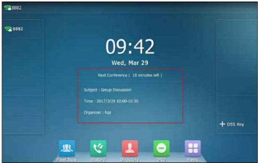
And there will be a Schedule menu on the menu screen. You can view all scheduled conference information in Schedule menu. The IP phone will not display the expired scheduled conference information. The scheduled conference information contains subject, conference ID, time, password, organizer and participants. If the conference organizer edits the conference content (e.g., time and participants) or cancel the conference via Yealink Meeting Server or Microsoft Outlook software after you have sent the invitation, the conference schedule will update in real time.
To view scheduled conference information in the Schedule menu:
-
Do one of the following:
-
Tap the Next Conference box on the idle screen.
- Tap ->Schedule.
The daily conference information will display as a list on the right of the touch screen.
- (Optional.) Tap a desired date on the calendar to view the schedule of selected day.
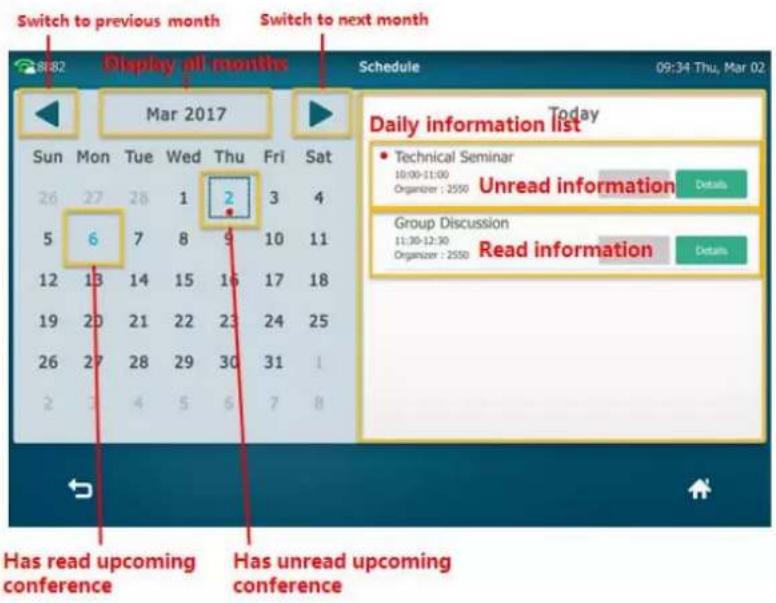
- Tap Detail to view the conference details.
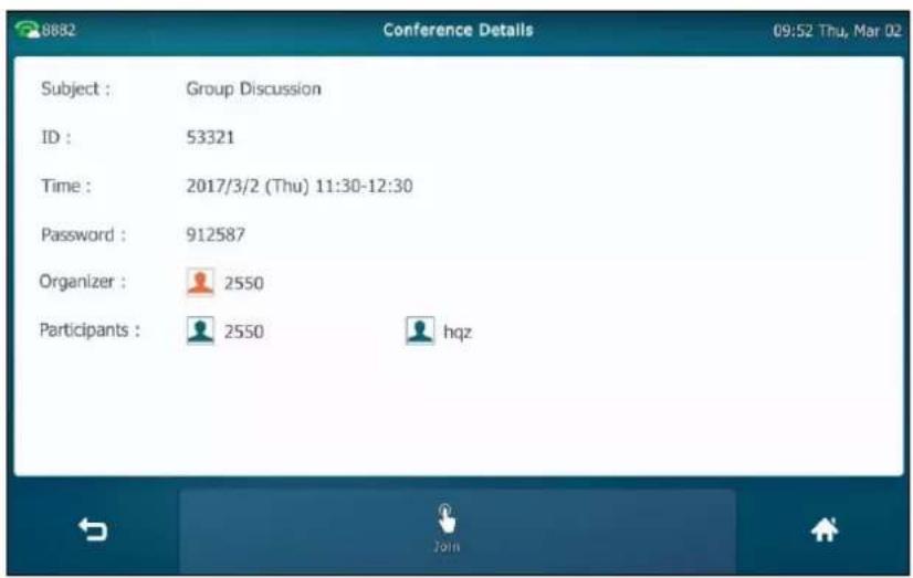
Joining a Scheduled Conference
You can join the scheduled conference in following ways:
- Joining a scheduled conference from a conference reminder
- Joining a scheduled conference from a conference invitation
- Joining a scheduled conference from notification center
- Joining a scheduled conference from the Schedule
• Dialing to join a scheduled conference
Joining a Scheduled Conference from a Conference Reminder
A pop-up reminder is displayed 5 minutes before the conference starts.
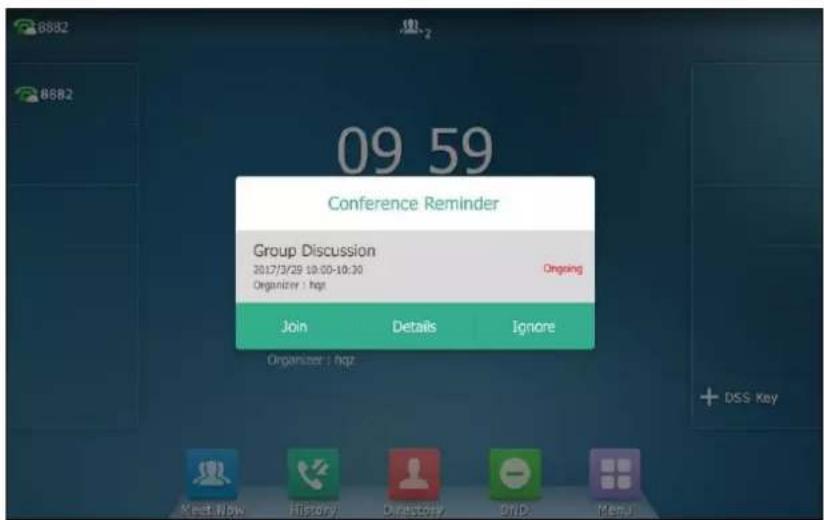
To join a conference from a conference reminder:
-
Do one of the following:
-
Tap Join to join the conference.
- Tap Details.

Tap the Join soft key to join the conference.
If you do not want to join the conference, you can tap Ignore to permanently remove the reminder from the screen and stop all future reminders for this schedule.
Note
If the IP phone is during a call, the touch screen will not pop up the reminder. In this case, if the scheduled conference is still ongoing when the call ends, the touch screen will pop up the reminder. If the scheduled conference has ended before the call ends, the touch screen will not pop up the reminder.
Joining a Scheduled Conference from a Conference Invitation
When the scheduled conference begins, the IP phone will receive a call that invites you to join the conference.
Note
This feature is available only if the enterprise administrator enables the automatic dialing feature. For more information on automatic dialing feature, refer to Yealink_Meeting_Server_Administrator.
To join a conference from a conference invitation:

1. When receiving the invitation, tap Answer to join the conference.
You can also do one of the following:
- Tap FWD to forward the incoming call to another contact.
Tap Silence to stop the phone from playing ring tone. - Tap Reject to decline the incoming call.
Note
If you enable the auto answer feature, the IP phone will join the scheduled conference automatically once you receive a conference invitation.
Joining a Scheduled Conference from Notification Center
If you register a YMS account successfully, the notification center will display an Ongoing
Conference tab.
By default, when the conference is about to take place in 5 minutes, the status bar displays the icon 🎨 and the notification center displays the conference information. You can tap the desired conference notification to join the conference in advance. Or during the conference, you can tap the desired conference notification to join the conference.
Note
The icon 📄 on the status bar has a counter indicating the number of ongoing conferences. For example, 📋 indicates there are 3 ongoing conferences.
The enterprise administrator can configure the time for the participants to join the conference in advance. For more information, refer to your enterprise administrator.
To join a conference from notification center during the conference duration:
- Swipe down from the top of the screen to enter the notification center.
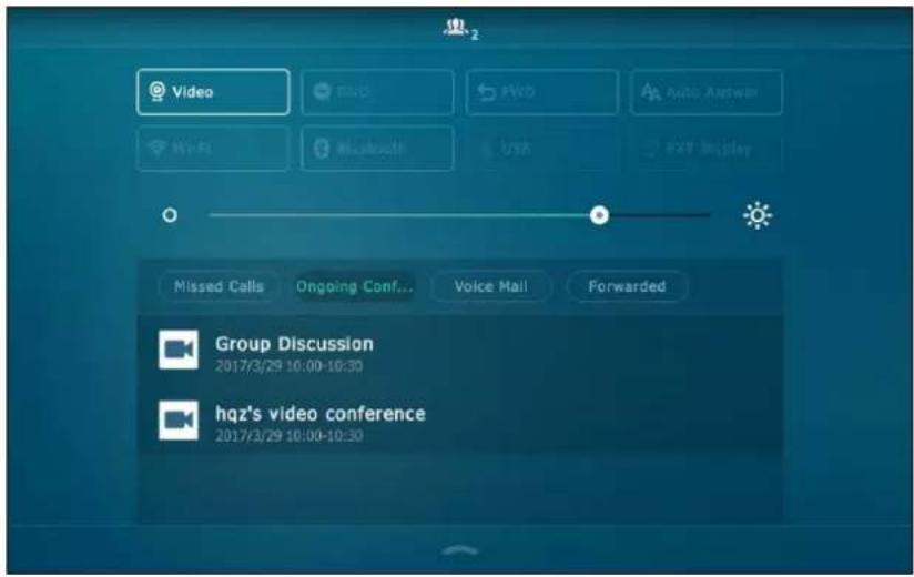
- Under the Ongoing Conference tab, tap the desired conference notification to join the conference.
Joining a Scheduled Conference from Schedule
By default, you can join a scheduled conference that is about to take place in 5 minutes or less.
Note
The enterprise administrator can configure when participants can join the scheduled conference. For more information, refer to your enterprise administrator.
To join a conference from Schedule:
- Do one of the following:
Tap the Next Conference box on the idle screen.
- Tap ->Schedule.
The daily conference information will display as a list on the right of the touch screen.
- Tap a desired date on the calendar to view the schedule of selected day.

- Do one of the following:
- Tap Join to join the conference.
- Tap Detail to view the conference details.

Tap the Join soft key to join the conference.
Dialing to Join a Scheduled Conference
If you schedule a conference or you are invited to join a scheduled conference, you can obtain the conference information in following ways:
- Invitee whose YMS account is associated with an email address will receive an email, which includes the IP address, conference ID, conference password and the way of joining a scheduled conference.
The following is an example of the email:

- The IP phone displays conference information, which includes the conference ID and conference password. For more information, refer to Viewing Scheduled Conference Information on page 310.
- Contact the conference participants.
The IP phone will fail to join the conference in the following scenario:
• The conference is expired.
- You enter the wrong conference information.
• The current time is more than 5 minutes before the scheduled start time.
Note
The enterprise administrator can configure the time for the participants to join the conference in advance. For more information, refer to your enterprise administrator.
To dial into a conference:
- Do one of the following:
If you register a YMS account, dial the conference ID to join the conference.
Obtain the conference information from your IP phone, your email or the other conference participants.
If you do not register a YMS account, dial the server address to join the conference.
Obtain the conference information from the other conference participants.
- To join from a SIP device, dial conference ID**conference password@server address or server address##conference ID**conference password to join the conference.
To join from a H.323 device, dial server address##conference ID**conference password to join the conference.
Obtain the conference information from the conference participants or your email address.
Meet Now
If you register a YMS account successfully, the idle screen will display a Meet Now shortcut key.
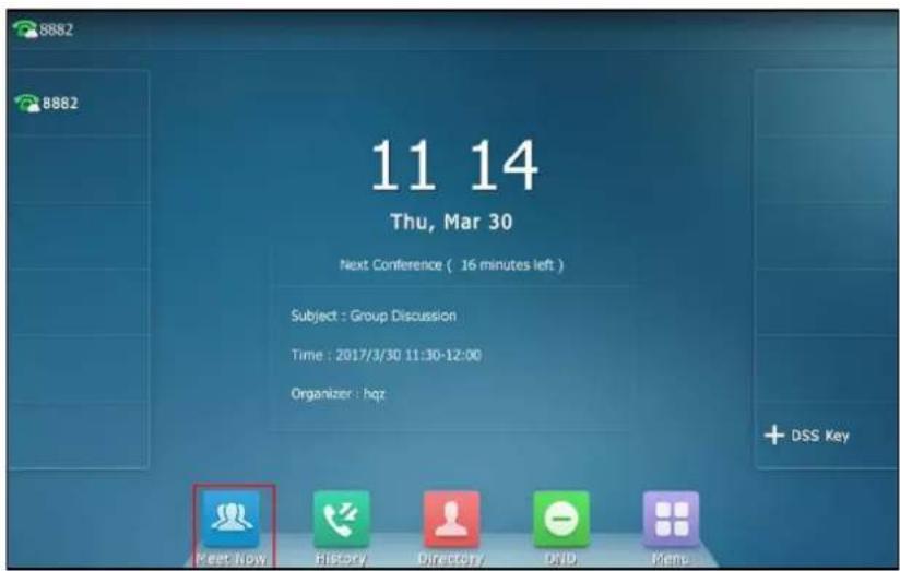
You can initiate a meet now conference by tapping at any time.
Initiating a Meet Now Conference
To initiate a meet now conference:
1.
Tap

The conference is initiated successfully.

Joining a Meet Now Conference
In the ongoing meet now conference, you can dial to join the conference. And you can obtain the conference information from the participants of meet now conference.
To dial to join a meet now conference, do one of the following:
- If you register a YMS account, you can dial the conference ID to join the conference.
- To join from a SIP device, dial conference ID**@server address or server address##conference ID to join the conference.
To join from a H.323 device, dial server address##conference ID to join the conference.
Permanent Virtual Meeting Room
Permanent VMR is a permanent virtual meeting room created by enterprise administrator. The conference ID of the permanent VMR is fixed, you can join the permanent VMR at any time.
You can join the permanent VMR in following ways:
- Joining a permanent VMR from enterprise directory
• Dialing to join a permanent VMR
Joining a Permanent VMR from Enterprise Directory
You can search and check the permanent VMR information then place a call to the permanent VMR from Enterprise directory.
Note
The enterprise administrator can determine whether to synchronize the permanent VMR to the IP phone. For more information, please refer to Yealink Meeting Server Administrator Guide.
To join a permanent VMR from enterprise directory:
1. Tap ->Enterprise Directory->Virtual Meeting Room.
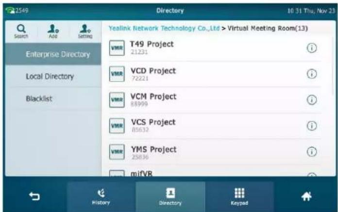
2. Do one of the following:
- Tap the desired permanent VMR.
- Tap ⓘ after the desired permanent VMR.
Tap Send to dial out the conference ID.
Dialing to Join a Permanent VMR
Do one of the following to dial to join a permanent VMR:
- If you register a YMS account, you can dial the conference ID to join the permanent VMR.
-
If you do not register a YMS account and the permanent VMR requires no password:
-
To join from a SIP device, dial conference ID**@server address or server address##conference ID to join the permanent VMR.
- To join from a H.323 device, dial server address##conference ID to join the permanent VMR.
- If you do not register a YMS account and the permanent VMR requires a password:
- To join from a SIP device, dial conference ID** conference password@server address or server address##conference ID**conference password to join the permanent VMR.
- To join from a H.323 device, dial server address##conference ID**conference password to join the permanent VMR.
YMS Conference Management
Inviting Conference Participants
During the YMS video conference, you can invite other YMS contacts to join the conference.
Note
You are not allowed to invite other YMS contacts to join the conference if you join the conference by dialing a URI.
To invite conference participants during the YMS video conference:

- Tap Invite.
- Do one of the following:
- Select the desired YMS contacts.

(Optional.) After selecting the desired YMS contacts, tap Selected on the top-right of the touch screen to view the selected YMS contacts.
Tap Invite on the top-right of the touch screen to send the invitation.
- Tap Select All checkbox to select all YMS contacts.
Tap Invite on the top-right of the touch screen to send the invitation.
- Tap the Keypad soft key.

Enter the desired number.
Press #seno, or tap Invite to send the invitation.
The invitees will join the conference as soon as they answer the call.
Note
If you fail to send invitation, you can re-send the invitation according to the prompt or contact your enterprise administrator.
Applying for Speaking
Not all conference participants need apply for speaking. If you join the Training mode scheduled conferences/permanent VMRs, all guests are muted automatically except moderators (or the organizer), guests need to wait for the moderator to appoint lecturers. If guests want to speak, they should apply for speaking. Only when the moderator allows the application, can they speak freely.
For more information on these two modes, refer to Yealink Meeting Server User Guide.
Note
In meet now conference, participants can speak freely.
To apply for speaking:
After joining a conference as a guest, the status bar prompts "Please press Mute to apply for speaking" in first 30 seconds.

1. Press
The status bar prompts "You are applying for speaking", and the icon 🤒 appears on top-left of the local-site video window.

The moderator will deal with the application on Yealink Meeting Server. For more information, refer to Yealink Meeting Server User Guide.
Hold/Resume
To place a conference on hold:
1. Press 📁 or tap the Hold soft key during a call.
The phone will beep softly every 30 seconds to remind you that you still have a conference on hold.
To resume a held conference:
1. Press 📁 or tap the Resume soft key.
Leaving Conference
All participants can leave the conference at any time.
To leave a conference:
- For the moderator (or organizer), tap the EndCall soft key.

Tap the Leave, others keep going.
- For other participants, tap the EndCall soft key.
Other participants remain connected.
Ending Conference
If you are the moderator (or organizer) of the YMS video conference, you can end the conference. After ending the conference, all participants are disconnected.
To end a conference:
1. Tap the EndCall soft key.

2. Tap End conference.
All participants are disconnected.
Third-Party Platform
Logging into Third-Party Platform
StarLeaf Cloud Platform
To log into StarLeaf Cloud platform:
- Tap ->Advanced (default password: admin) ->VC Account->Cloud Account.
- Tap the desired account.
- Tap the Type field.
-
Tap StarLeaf in the pop-up dialog box.
-
Enter the quick access code in QCP field. Contact your Cloud enterprise administrator for more information.
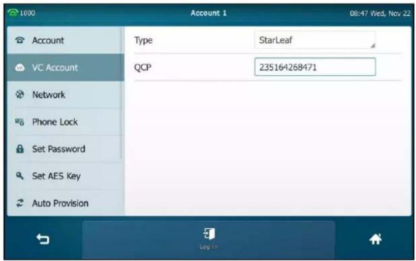
- Tap the Log in soft key.
Note
The QCP code can be used only once.
StarLeaf Cloud account is configurable via web user interface at the path Account->Cloud Account.
Zoom Cloud Platform
To log into Zoom Cloud platform:
-
Tap ->Advanced (default password: admin) ->VC Account->Cloud Account.
-
Tap the desired account.
- Tap the Type field.
- Tap Zoom in the pop-up dialog box.
-
(Optional.) Enter the desired value in Label field.
-
Enter the desired value in Server field. Contact your Cloud enterprise administrator for more information.

- Tap the Log in soft key.
Zoom Cloud account is configurable via web user interface at the path Account->Cloud Account.
Pexip Platform
To log into Pexip platform:
- Tap ->Advanced (default password: admin) ->VC Account->Cloud Account.
- Tap the desired account.
- Tap the Type field.
- Tap Pexip in the pop-up dialog box.
- (Optional.) Enter the desired value in Alias field.
-
Enter the desired value in User Name, Password and Server field respectively. Contact your Cloud enterprise administrator for more information.
-
(Optional.) Tap the Remember the Password checkbox.

- Tap the Log in soft key.
Pexip account is configurable via web user interface at the path Account->Cloud Account.
BlueJeans Cloud Platform
To log into BlueJeans Cloud platform:
- Tap ->Advanced (default password: admin) ->VC Account->Cloud Account.
- Tap the desired account.
- Tap the Type field.
- Tap BlueJeans in the pop-up dialog box.
- (Optional.) Enter the desired value in Label field.
- Enter the desired value in Server field. Contact your Cloud enterprise administrator for more information.
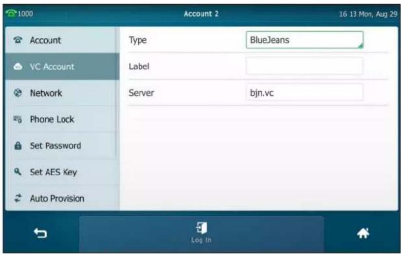
- Tap the Log in soft key.
BlueJeans Cloud account is configurable via web user interface at the path Account->Cloud Account.
Mind Platform
To log into Mind platform:
- Tap ->Advanced (default password: admin) ->VC Account->Cloud Account.
- Tap the desired account.
- Tap the Type field.
- Tap Mind in the pop-up dialog box.
- (Optional.) Enter the desired value in Label field.
- Enter the desired value in Server field. Contact your Cloud enterprise administrator for more information.

- Tap the Log in soft key.
Mind account is configurable via web user interface at the path Account->Cloud Account.
Custom Platform
To log into Custom platform:
- Tap ->Advanced (default password: admin) ->VC Account->Cloud Account.
- Tap the desired account.
- Tap the Type field.
- Tap Custom in the pop-up dialog box.
- Enter the desired value in Label, User Name, Register Name, Password and Server field respectively. Contact your Cloud enterprise administrator for more information.
- (Optional.) Tap the Remember the Password checkbox.
- Tap the Log in soft key.
Custom account is configurable via web user interface at the path Account->Cloud Account.
Using Third-Party Platform
For StarLeaf/Pexip account, you are allowed to dial other account and join meetings. For Zoom/BlueJeans/Mind account, you are only allowed to join meetings.
For a custom account, you can use the corresponding platform feature.
Dialing StarLeaf/Pexip Account
To dial StarLeaf/Pexip accounts:
- Tap the StarLeaf/Pexip line key.
- Enter the desired account number.
- Tap Send.
Joining the Third-Party Platform Meeting
You can join the third-party platform meeting in following ways:
• Dialing to join the third-party platform meeting
- Joining the third-party meeting by 3rd-party VMR key
Dialing to Join the Third-Party Platform Meeting
You can dial out the meeting ID to join the meeting.
To join a meeting:
- Tap the StarLeaf/Zoom/BlueJeans/Pexip/Mind line key.

-
Enter the meeting ID (for StarLeaf/Zoom/BlueJeans/Mind platform) or conference alias/URI (for Pexip platform).
-
Press #send , or tap Send.
Then you join to the meeting.
Note
For Zoom/BlueJeans platform, if you enter nothing or enter wrong information, you can still be sent to the Zoom/BlueJeans welcome screen. Follow the voice prompt to join the meeting.
Joining the Third-Party Meeting by 3rd-party VMR Key
If you haven't logged into the third-party platform or you only log into the Yealink VC Cloud Management Service platform/Yealink Meeting Server, you can configure a 3rd-party VMR key to quickly join a meeting. It is only applicable to Zoom/BlueJeans/Custom platform.
To configure a 3rd-party VMR key via phone user interface:
- Tap ->Features->DSS Keys.
- Tap the desired line key.
- Tap the Type field.
- Tap 3rd-party VMR in the pop-up dialog box.
- Tap the Platform field.
- Tap the desired platform in the pop-up dialog box.
- (Optional.) Enter the string that will appear on the touch screen in the Label field.
- Enter the ID for the meeting room in the Meeting ID field.
- Enter the IP or FQDN of the platform in the IP/FQDN field.

- Tap the Save soft key to accept the change or ↩ to cancel.
3rd-party VMR key is configurable via web user interface at the path DSSKey->Line key.
To join a meeting by using a 3rd-party VMR key:
- Tap the 3rd-party VMR key.
Then you join to the meeting.
Receiving Presentations
During the video call, the IP phone supports receiving presentations to meet the requirements of different conference scenarios, such as training or medical consultation. You can see the contents that the presenter wants to show you. To receive presentations, you should enable the BFCP protocol (for YMS/Zoom/Pexip/BlueJeans/Mind/Custom account) or H.239 protocol (for StarLeaf account) first. The Yealink Cloud account supports receiving presentations by default, and it cannot be configured.
The following figures show an example of phone screen display during a video call when receiving presentation (H.239 or BFCP protocol is enabled):

The shared contents are shown on the second screen, you can swipe to return to the video call screen.
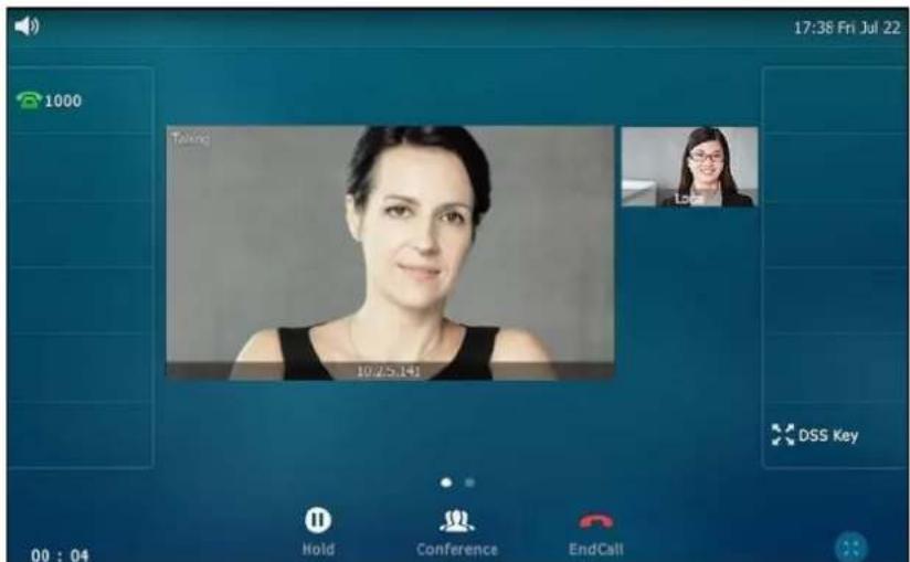
The following figures show an example of phone screen display during a video call when receiving presentations (both H.239 and BFCP protocols are disabled):
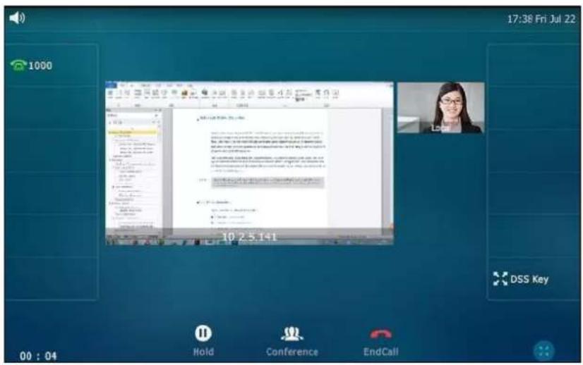
To configure BFCP protocol via web user interface:
- Click on Account->Cloud Account.
- Select the desired account from the pull-down list of Account.
- Select Enabled from the pull-down list of BFCP.

- Click Confirm to accept the change.
Note
BFCP is configurable via web user interface only.
To configure H.239 protocol via web user interface (for StarLeaf Cloud account):
- Click Account->Cloud Account.
2. Select a desired value from the pull-down list of H.239.

3. Click Confirm to accept the change.
Note
H.239 for StarLeaf Cloud account is configurable via web user interface only.
H.323 Settings
The SIP VP-T49G IP phone only support SIP protocol by default, after enabling the video conferencing feature (refer to Video Conferencing), the IP phone can also support H.323 call protocols. You can register an H.323 account to directly communicate with H.323 endpoints.
Registering a H.323 Account
To register an H.323 account via phone user interface:
- Tap ->Advanced (default password: admin) ->VC Account->H.323.
- Enter the desired value in the corresponding field respectively. Contact your system administrator for more information.

- Tap the Save soft key to accept the change or ↩ to cancel.
H.323 account is configurable via web user interface at the path Account->H.323.
After successful registration, you can configure a line key for H.323 account. For more information, refer to Line on page 139.
Allow H.323 IP Call
You can configure H.323 protocol to enable or disable the IP phone to place/receive H.323 IP call. If SIP/H.323 IP call is both enabled, the IP phone will select desired type according to this priority: H.323 IP call > SIP IP call.
To enable H.323 protocol via phone user interface:
- Tap ->Advanced (default password: admin) ->VC Account->H.323.
- Tap the H.323 Protocol field.
- Tap Enabled in the pop-up dialog box.
- Tap the Save soft key to accept the change or ↩ to cancel.
Auto Answer
You can configure the H.323 Auto Answer feature to enable or disable the IP phone to automatically answer the incoming H.323 calls. Auto answer is only applicable when there is no other call in progress on the phone.
To configure H.323 auto answer feature via phone user interface:
- Tap ->Features->Auto Answer.
- Tap the On radio box in the H.323 field.
This field appears only if you enable the video conferencing feature (refer to Video Conferencing).

- Tap the Save soft key to accept the change or ↩ to cancel.
H.323 auto answer is configurable via web user interface at the path Account->H.323.
Receiving Presentations
During the video call, the IP phone supports receiving presentations to meet the requirements of different conference scenarios, such as training or medical consultation. You can see the contents that the presenter wants to show you. To receive presentations, you should enable the H.239 protocol first.
The following figures show an example of phone screen display during a video call when receiving presentation (H.239 is enabled):

The shared contents are shown on the second screen, you can swipe to return to the video call screen.

The following figures show an example of phone screen display during a video call when receiving presentations (H.239 is disabled):

To configure H.239 via phone user interface:
- Tap ->Advanced (default password: admin) ->VC Account->H.323.
- Tap the H.239 field.
- Tap the desired value in the pop-up dialog box.

- Click Confirm to accept the change.
H.239 is configurable via web user interface at the path Account->H.323.
SIP IP Call Settings
The IP phone supports SIP IP call by default, and it cannot be configured. After enabling the video conferencing feature (refer to Video Conferencing), the IP phone support configuring SIP IP call feature.
Allow SIP IP Call
The IP phone supports SIP IP call by default. You can disable the SIP IP call feature, and the IP phone cannot place or receive SIP IP call. If SIP/H.323 IP call is both enabled, the IP phone will select desired type according to this priority: H.323 IP call > SIP IP call.
To configure the allow SIP IP call via phone user interface:
- Tap ->Advanced (default password: admin) ->VC Account->SIP IP Call.
- Tap the IP Call field.
- Tap the desired value in the pop-up dialog box.

- Tap the Save soft key.
Allow SIP IP call is configurable via web user interface at the path Account->SIP IP Call.
Auto Answer
You can configure the SIP IP Call Auto Answer feature to enable or disable the IP phone to automatically answer the incoming SIP IP calls. Auto answer is only applicable when there is no other call in progress on the phone.
To configure the allow SIP call IP call via phone user interface:
- Tap ->Advanced (default password: admin) ->VC Account->SIP IP Call.
-
Tap the IP Call Auto Answer field.
-
Tap the desired value in the pop-up dialog box.

- Tap the Save soft key.
SIP IP Call Auto Answer is configurable via web user interface at the path Account->SIP IP Call.
Receiving Presentations
During the video call, the IP phone supports receiving presentations to meet the requirements of different conference scenarios, such as training or medical consultation. You can see the contents that the presenter wants to show you. To receive presentations, you should enable the BFCP protocol first.
The following figures show an example of phone screen display during a video call when receiving presentation (BFCP protocol is enabled):

The shared contents are shown on the second screen, you can swipe to return to the video call screen.

The following figures show an example of phone screen display during a video call when receiving presentations (BFCP protocols is disabled):

To configure BFCP protocol for SIP IP call via phone user interface:
-
Tap ->Advanced (default password: admin) ->VC Account->SIP IP Call.
-
Tap the BFCP field.
-
Tap the desired value in the pop-up dialog box.

- Tap the Save soft key.
BFCP for SIP IP call is configurable via web user interface at the path Account->SIP IP Call.
Call Stats Key
If voice quality is poor during a call, you can tap call stats key to view the current status of the call to find out why.
Codec, bandwidth, total packet lost and other parameters about presentation are included in the call stats. For example, when a delay occurs or the video has a 'mosaic' look, you can view the total packet loss to check whether the packet has been lost.
Before configuring a call stats key, you should enable the video conferencing feature (refer to Video Conferencing) first.
To configure a call stats key via phone user interface:
- Tap ➕→Features→DSS Keys.
- Tap the desired line key.
- Tap the Type field.
- Tap Key Event in the pop-up dialing box.
- Tap the Key Type field.
-
Tap Call Stats in the pop-up dialog box.
-
(Optional.) Enter the string that will appear on the touch screen in the Label field.
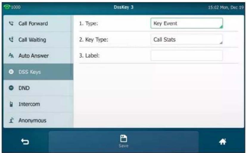
- Tap the Save soft key to accept the change or ↩ to cancel.
Call stats key is configurable via web user interface at the path DSSKey->Line key.
To check call stats via phone user interface:
- Tap the call stats key during the call.
The call stats will be displayed as below:

Check the call stats via web user interface at the path Status->Talk Statistics.
Videoconferencing Key
You can use videoconferencing key to make a video call, to set up a video conference or add a party to the conference. Before configuring a videoconferencing key, you should enable the video conferencing feature (refer to Video Conferencing) first.
To configure a videoconferencing key via phone user interface:
- Tap → Features → DSS Keys.
- Tap the desired line key.
- Tap the Type field.
- Tap Videoconferencing in the pop-up dialing box.
- Tap the Account ID field.
- Tap the desired line in the pop-up dialog box.
- (Optional.) Enter the string that will appear on the touch screen in the Label field.
- (Optional.) Enter the IP/URI that will be added to the conference in the IP/URI field. If you leave it blank, the videoconferencing key will perform the same function as Conference soft key during a video call.
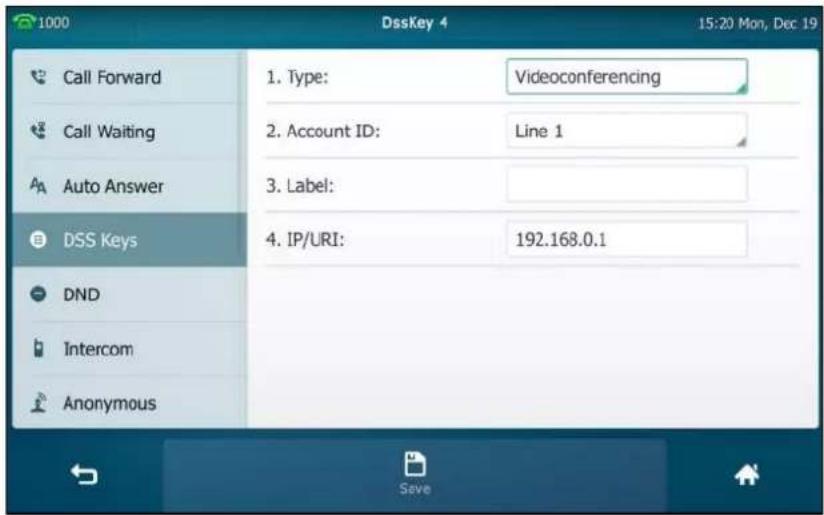
- Tap the Save soft key to accept the change or ↩ to cancel.
Videoconferencing key is configurable via web user interface at the path DSSKey->Line key.
To make a video call using a videoconferencing key:
- Tap the videoconferencing key when the phone is idle.
To set up a video conferencing using a videoconferencing key:
- Tap the videoconferencing key during the video call.
When the party (specified in the IP/URI field) answers, the three-way video conference is set up.
To add a party to the video conference using a videoconferencing key:
- Tap the videoconferencing key during the three-way video conference call.
When the party (specified in the IP/URI field) answers, the party is added to the conference and the call between the party and others is audio-only.
Appendix
Appendix A - Time Zones
| Time Zone | Time Zone Name |
| -11 | Samoa |
| -10 | United States-Hawaii-Aleutian, United States-Alaska-Aleutian |
| -9:30 | French Polynesia |
| -9 | United States-Alaska Time |
| -8 | Canada(Vancouver,Whitehorse), Mexico(Tijuana,Mexicali), United States-Pacific Time |
| -7 | Canada(Edmonton,Calgary), Mexico(Mazatlan,Chihuahua), United States-MST no DST, United States-Mountain Time |
| -6 | Canada-Manitoba(Winnipeg), Chile(Easter Islands), Mexico(Mexico City,Acapulco), United States-Central Time |
| -5 | Bahamas(Nassau), Canada(Montreal,Ottawa,Quebec), Cuba(Havana), United States-Eastern Time |
| -4:30 | Venezuela(Caracas) |
| -4 | Canada(Halifax,Saint John), Chile(Santiago), Paraguay(Asuncion), United Kingdom-Bermuda(Bermuda), United Kingdom(Falkland Islands), Trinidad&Tobago |
| -3:30 | Canada-New Foundland(St.Johns) |
| -3 | Argentina(Buenos Aires), Brazil(DST), Brazil(no DST), Denmark-Greenland(Nuuk) |
| -2:30 | Newfoundland and Labrador |
| -2 | Brazil(no DST) |
| -1 | Portugal(Azores) |
| 0 | Denmark-Faroe Islands(Torshavn), GMT, Greenland, Ireland(Dublin), Morocco, Portugal(Lisboa,Porto,Funchal), Spain-Canary Islands(Las Palmas), United Kingdom(London) |
| +1 | Albania(Tirane), Austria(Vienna), Belgium(Brussels), Caicos, Chad, Croatia(Zagreb), Czech Republic(Prague), Denmark(Kopenhagen), France(Paris), Germany(Berlin), Hungary(Budapest), Italy(Rome), Luxembourg(Luxembourg), Macedonia(Skopje), Namibia(Windhoek), Netherlands(Amsterdam), Spain(Madrid) |
| +2 | Estonia(Tallinn), Finland(Helsinki), Gaza Strip(Gaza), Greece(Athens), Israel(Tel Aviv), Jordan(Amman), Latvia(Riga), Lebanon(Beirut), Moldova(Kishinev), Romania(Bucharest), Russia(Kaliningrad), Syria(Damascus), Turkey(Ankara), Ukraine(Kyiv, Odessa) |
| +3 | East Africa Time, Iraq(Baghdad), Russia(Moscow) |
| +3:30 | Iran(Teheran) |
| +4 | Armenia(Yerevan), Azerbaijan(Baku), Georgia(Tbilisi), Kazakhstan(Aktau), Russia(Samara) |
| +4:30 | Afghanistan(Kabul) |
| +5 | Kazakhstan(Aqtobe), Kyrgyzstan(Bishkek), Pakistan(Islamabad), Russia(Chelyabinsk) |
| +5:30 | India(Calcutta) |
| +5:45 | Nepal(Katmandu) |
| +6 | Kazakhstan(Astana, Almaty), Russia(Novosibirsk,Omsk) |
| +6:30 | Myanmar(Naypyitaw) |
| +7 | Russia(Krasnoyarsk), Thailand(Bangkok) |
| +8 | Australia(Perth), China(Beijing), Russia(Irkutsk, Ulan-Ude), Singapore(Singapore) |
| +8:45 | Eucla |
| +9 | Japan(Tokyo), Korea(Seoul), Russia(Yakutsk,Chita) |
| +9:30 | Australia(Adelaide), Australia(Darwin) |
| +10 | Australia(Brisbane), Australia(Hobart), Australia(Sydney,Melbourne,Canberra), Russia(Vladivostok) |
| +10:30 | Australia(Lord Howe Islands) |
| +11 | New Caledonia(Noumea), Russia(Srednekolymsk Time) |
| +11:30 | Norfolk Island |
| +12 | New Zealand(Wellington,Auckland), Russia(Kamchatka Time) |
| +12:45 | New Zealand(Chatham Islands) |
| +13 | Tonga(Nukualofa) |
| +13:30 | Chatham Islands |
| +14 | Kiribati |
Appendix B – Menu Structure
![graph TD A["Menu"] --> B["Status"] A --> C["Features"] A --> D["Basic"] A --> E["Advanced (default password: admin)"] A --> F["Message"] A --> G["History"] A --> H["Directory"] A --> I["USB"] B --> B1["General"] B --> B2["Network"] B --> B3["Phone"] B --> B4["Accounts"] C --> C1["Call Forward"] C --…](/content/2026/07/1418761/images/605ab0a2dff04ba3c09209a7b26189c1b54430bdbeddb9aed3fab57d1e379487.jpg)
Index
A
About This Guide v
Accessing the Remote Phone Book 109
Account Management 147
Activating the Bluetooth Mode 124
Adding a Contact to the Blacklist 116
Adding Contacts 93
Adding Groups 90
Administrator Password 80
Advanced Phone Features 229
Allow SIP IP Call 337
Anonymous Call 221
Anonymous Call Rejection 222
Answering Calls 165
Appendix A - Time Zones 343
Appendix B - Menu Structure 345
Applying for Speaking 321
Attended Transfer 210
Area Code 155
Audio Settings 84
Auto Answer 185
Auto Redial 186
B
Backlight 71
Barging In an Active Call 273
Basic Network Settings 52
Basic Phone Features 161
Blacklist 107
Blind Transfer 208
Block Out 156
Bluetooth Headset 121
Bluetooth-Enabled Mobile Phone 129
Busy Lamp Field (BLF) 229
BLF List 236
C
Call and Conference Recording Using a USB
Flash Drive 238
Call Completion 188
Call Forward 198
Call Mute 190
Call History Management 113
Call Hold/Resume 191
Call Park 216
Call Pickup 217
Capturing Screenshots during a Video Call 224
Call Recording Using a Record Key 244
Call Record 239
Call Stats 340
Call Transfer 208
Call Waiting 211
Changing Video Call Settings 167
Changing the Video Settings 173
Changing the Clarity of Local-Site Video 168
Changing the Video Layout during Calls 174
Changing the Wallpaper via Phone User Interface 65
Conference 212
Conference Recording 241
Configuring an Access URL 109
Configuring the BLF Feature on the Phone 229
Configuring SCA Feature on the IP Phone 261
Configuring the Screen Saver via Web User Interface 69
Configuration Screen Display 40
Connecting to the Wired Network 38
Connecting to the Wireless Network 39
Contact Management 88
Control Center/Notification Center 46
Creating a Meet Now Conference 318
Customizing Your Phone 65
D
Deactivating the Bluetooth Mode 129
Default Account 147
Deleting Contacts 98
Deleting Groups 92
Deleting History Records 117
Deleting the Paired Bluetooth Headset 127
Disabling Wi-Fi Feature 63
Dial-now 153
Dial Plan 151
Disabling History Records 119
Disconnecting the Bluetooth Headset 127
Disconnecting the Wireless Network
Connection 63
Do Not Disturb (DND) 193
Documentations 32
DSS Keys 136
Dual Headset 123
Dynamic Forwarding 198
E
Editing Contacts 97
Editing Groups 91
Emergency Number 157
Ending Calls 167
Entering Data and Editing Fields 47
External Monitor 180
G
General Settings 65
Gestures 45
Getting Started 33
H
Hardware Component Instructions 17
Headset Use 121
Headset Mode Activation/Deactivation 121
Headset Prior 122
Hotline 158
Hot Desking 247
H.323 Settings 3 3 3
I
Icon Instructions 20
Idle Clock 76
Idle Screen Display 40
Importing/Exporting Contact lists 104
In This Guide v
Incoming/Outgoing Call Lookup 110
Incoming Intercom Calls 251
Intercom 250
J
Joining a Scheduled Conference 311
Joining a Meet Now Conference 318
K
Key as Send 81
Key Tone 88
L
Language 75
Leaving Conferences 318
LED Instructions 26
Line Keys 136
Live Dialpad 157
Local Conference 212
Local Directory 89
M
Making a Mobile Phone Call by using the IP
Phone 134
Managing the Saved Wireless Network 61
Manually Add a Wireless Network 59
Manually Connect an Available Wireless
Network 55
Meet Now 317
Message Waiting Indicator (MWI) 284
Messages 277
Mobile Contacts 111
Multicast Paging 253
Multiple Line Keys per Account 150
Music on Hold 259
N
Navigating Menus and Fields 45
Network Conference 215
Network Connection 38
0
Outgoing Intercom Calls 250
Overview 17
Optional Accessories 35
P
Packaging Contents 33
Pairing and Connection the
Bluetooth-Enabled Mobile Phone 129
Pairing and Connecting the Bluetooth
Headset 125
Permanent Virtual Meeting Room 318
Phone Initialization 39
Phone Installation 35
Phone Lock 81
Phone Status 50
Phone User Interface 27
Placing a Call from History Records 115
Power Saving 71
Previewing the Local-Site Video 178
Programable Key 146
Placing Calls 162
Placing Calls to Contacts 102
R
Recent Call In Dialing 184
Receiving Mobile Phone Calls by using the IP
Phone 136
Receiving Presentations 338
Receiving RTP Stream 256
Recall 189
Recorded Calls Playback 241
Redialing Numbers 180
Registration 40
Remote Phone Book 109
Replace Rule 152
Ring Tones 86
S
Scheduled Conference 309
Screen Saver 68
Search Source List in Dialing 119
Searching for Contacts 103
Semi-Attended Transfer 209
Sending RTP Stream 253
Setting Wallpaper by Using USB Flash Drive 67
Setup Wizard 287
Short Message Service (SMS) 277
Share Call Appearance (SCA) 260
SIP Account Registration 147
SIP IP Call Settings 336
Auto Answer 185
Site Name 71
Static Forwarding 198
Stopping Transmitting Video during a Call 167
Storage Space 244
Summary of Changes vi
Syncing the Mobile Contacts to the IP Phone 133
System Customizations 119
T
Table of Contents xi
Touch Screen Display 40
Time & Date 76
Third-Party Platform 324
U
Uploading Contact Photos 100
Uploading the Custom Wallpaper via Web
User Interface 66
Uploading the Custom Picture via Web User Interface 69
User Interfaces 27
Using BLF Feature on the Phone 234
Using SCA Feature on the IP Phone 268
Using the Onscreen Keyboard 47
Using the Phone Keypad and Dial Pad 50
Using Intercom 252
Using Multicast Paging 257
V
Viewing Scheduled Conference Information 310
Viewing History Records 114
Viewing the Pictures Stored in Your USB
Flash Drive 226
Viewing the Wireless Network Information 60
Video Call Screen Display 43
Video Call Full-Screen Display (Both Far- and
Near- Site Videos Exits) 44
Video Conferencing 286
Video Conferencing Features 286
Video Conferencing Platform 288
Videoconferencing Key 341
Video/Voice Mail 281
Volume 84
W
Wallpaper 65
Web User Interface 28
Wi-Fi Protected Setup (WPS) 57
Wireless Network Settings 55
Y
Yealink VC Cloud Management Service
Platform 288
Yealink Meeting Server 306
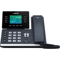
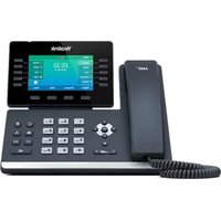
- ULTRA-ELEGANT GIGABIT IP PHONE SIP VP-T49G USER GUIDE
- COPYRIGHT
- COPYRIGHT © 2017 YEALINK (XIAMEN) NETWORK TECHNOLOGY
- TRADEMARKS
- WARRANTY
- DISCLAIMER
- LIMITATION OF LIABILITY
- END USER LICENSE AGREEMENT
- PATENT INFORMATION
- CUSTOMER FEEDBACK
- TECHNICAL SUPPORT
- GNU GPL INFORMATION
- ABOUT THIS GUIDE
- IN THIS GUIDE
- TYPOGRAPHIC CONVENTIONS
- TERMS
- SUMMARY OF CHANGES
- CHANGES FOR RELEASE 25, GUIDE VERSION 25.1
- CHANGES FOR RELEASE 24, GUIDE VERSION 24.1
- CHANGES FOR RELEASE 23, GUIDE VERSION 23.20
- CHANGES FOR RELEASE 23, GUIDE VERSION 23.5
- CHANGES FOR RELEASE 22, GUIDE VERSION 22.5
- CHANGES FOR RELEASE 80, GUIDE VERSION 80.108
- CHANGES FOR RELEASE 80, GUIDE VERSION 80.75
- TABLE OF CONTENTS
- ABOUT THIS GUIDE ...... V
- TABLE OF CONTENTS....XI
- OVERVIEW....17
- GETTING STARTED....33
- CUSTOMIZING YOUR PHONE....65
- BASIC PHONE FEATURES....161
- ADVANCED PHONE FEATURES....229
- APPENDIX....343
- INDEX 347
- OVERVIEW
- HARDWARE COMPONENT INSTRUCTIONS
- ICON INSTRUCTIONS
- FEATURE STATUS ICONS
- LINE KEY ICONS
- ICON INDICATOR (ASSOCIATED WITH A SHARED LINE)
- OTHER ICONS
- LED INSTRUCTIONS
- NOTE
- USER INTERFACES
- PHONE USER INTERFACE
- WEB USER INTERFACE
- DOCUMENTATIONS
- GETTING STARTED
- PACKAGING CONTENTS
- OPTIONAL ACCESSORIES
- PHONE INSTALLATION
- CONNECT THE AC POWER
- CONNECT THE OPTIONAL USB FLASH DRIVE
- CONNECT THE OPTIONAL EXTERNAL MONITOR
- NETWORK CONNECTION
- CONNECTING TO THE WIRED NETWORK
- CONNECTING TO THE WIRELESS NETWORK
- PHONE INITIALIZATION
- AUTOMATIC PHONE INITIALIZATION
- DHCP (DYNAMIC HOST CONFIGURATION PROTOCOL)
- REGISTRATION
- TOUCH SCREEN DISPLAY
- IDLE SCREEN DISPLAY
- A
- VIDEO CALL FULL-SCREEN DISPLAY (BOTH FAR- AND LOCAL-SITE VIDEOS EXIST)
- NAVIGATING MENUS AND FIELDS
- GESTURES
- CONTROL CENTER/NOTIFICATION CENTER
- ENTERING DATA AND EDITING FIELDS
- USING THE ONSCREEN KEYBOARD
- TO USE ONSCREEN KEYBOARD
- USING THE PHONE KEYPAD AND DIAL PAD
- PHONE STATUS
- TO VIEW THE PHONE STATUS VIA PHONE USER INTERFACE
- 1
- TO VIEW THE PHONE STATUS VIA WEB USER INTERFACE
- BASIC NETWORK SETTINGS
- TO CONFIGURE THE IP MODE VIA PHONE USER INTERFACE
- TO CONFIGURE A STATIC IPV4 ADDRESS VIA PHONE USER INTERFACE
- TO CONFIGURE A STATIC IPV6 ADDRESS VIA PHONE USER INTERFACE
- TO CONFIGURE PPPOE VIA PHONE USER INTERFACE
- WIRELESS NETWORK SETTINGS
- MANUALLY CONNECT TO AN AVAILABLE WIRELESS NETWORK
- TO MANUALLY CONNECT TO AN AVAILABLE WIRELESS NETWORK VIA PHONE USER INTERFACE
- WI-FI PROTECTED SETUP (WPS)
- PUSH BUTTON CONFIGURATION (PBC)
- TAP THE ON RADIO BOX IN THE WI-FI FIELD
- TAP THE WPS SOFT KEY
- LONG PRESS THE WPS KEY ON YOUR GATEWAY/ROUTER
- PERSONAL IDENTIFICATION NUMBER (PIN)
- TO CONNECT TO THE WIRELESS NETWORK USING PIN METHOD
- TAP ->BASIC->WI-FI
- TAP THE WPS-PIN SOFT KEY
- MANUALLY ADD A WIRELESS NETWORK
- TO ADD A WIRELESS NETWORK
- TAP THE ADD SOFT KEY
- VIEWING THE WIRELESS NETWORK INFORMATION
- MANAGING THE SAVED WIRELESS NETWORK
- TAP THE STORAGE NETWORK TO VIEW THE SAVED WIRELESS NETWORKS
- TAP ⋯
- DO THE FOLLOWING
- DISCONNECTING THE WIRELESS NETWORK CONNECTION
- TO DISCONNECT THE WIRELESS NETWORK
- DISABLING WI-FI FEATURE
- CUSTOMIZING YOUR PHONE
- GENERAL SETTINGS
- WALLPAPER
- CHANGING THE WALLPAPER VIA PHONE USER INTERFACE
- UPLOADING THE CUSTOM WALLPAPER VIA WEB USER INTERFACE
- SETTING WALLPAPER BY USING USB FLASH DRIVE
- TO SET A PICTURE IN THE USB FLASH DRIVE AS THE WALLPAPER
- SCREEN SAVER
- THE SCREEN SAVER WILL BE STOPPED WHEN
- UPLOADING THE CUSTOM PICTURE VIA WEB USER INTERFACE
- CONFIGURING THE SCREEN SAVER
- TO CONFIGURE THE SCREEN SAVER VIA WEB USER INTERFACE
- POWER SAVING
- THE IP PHONE WILL EXIT POWER-SAVING MODE IF A PHONE EVENT OCCURS
- CONFIGURING THE OFFICE HOUR VIA WEB USER INTERFACE
- TO CONFIGURE THE OFFICE HOUR VIA WEB USER INTERFACE
- CONFIGURING THE IDLE TIMEOUT VIA WEB USER INTERFACE
- TO CONFIGURE THE IDLE TIMEOUT VIA WEB USER INTERFACE
- SITE NAME
- TO CONFIGURE THE SITE NAME VIA PHONE USER INTERFACE
- BACKLIGHT
- TO CONFIGURE THE BACKLIGHT VIA PHONE USER INTERFACE
- LANGUAGE
- TO CHANGE THE LANGUAGE FOR THE PHONE USER INTERFACE
- TO CHANGE THE LANGUAGE FOR THE WEB USER INTERFACE
- IDLE CLOCK
- TO HIDE THE IDLE CLOCK VIA PHONE USER INTERFACE
- TAP THE OFF RADIO BOX IN THE IDLE CLOCK DISPLAY FIELD
- TAP THE SAVE SOFT KEY
- TIME & DATE
- TO CONFIGURE THE SNTP SETTING VIA PHONE USER INTERFACE
- TAP ->BASIC->TIME & DATE->GENERAL
- ADMINISTRATOR PASSWORD
- KEY AS SEND
- TO CONFIGURE KEY AS SEND VIA PHONE USER INTERFACE
- PHONE LOCK
- TO ACTIVATE THE PHONE LOCK VIA PHONE USER INTERFACE
- TO UNLOCK THE PHONE VIA PHONE USER INTERFACE
- TO CHANGE THE PHONE UNLOCK PIN VIA PHONE USER INTERFACE
- TO DEACTIVATE THE PHONE LOCK VIA PHONE USER INTERFACE
- AUDIO SETTINGS
- VOLUME
- TO ADJUST THE VOLUME WHEN THE PHONE IS IDLE
- TO ADJUST THE VOLUME WHEN THE PHONE IS RINGING
- TO ADJUST THE VOLUME WHEN THE PHONE IS DURING A CALL
- RING TONES
- TO SELECT A RING TONE FOR THE PHONE VIA PHONE USER INTERFACE
- KEY TONE
- TAP THE ON RADIO BOX IN THE KEY TONE FIELD
- TAP THE SAVE SOFT KEY TO ACCEPT THE CHANGE OR ↩ TO CANCEL
- CONTACT MANAGEMENT
- LOCAL DIRECTORY
- ADDING GROUPS
- EDITING GROUPS
- DELETING GROUPS
- ADDING CONTACTS
- ADDING CONTACTS MANUALLY
- ADDING CONTACTS FROM CALL HISTORY
- ADDING CONTACTS FROM A REMOTE PHONE BOOK
- EDIT THE CORRESPONDING FIELDS
- TAP THE SAVE SOFT KEY TO SAVE THE CONTACT TO THE LOCAL DIRECTORY
- EDITING CONTACTS
- TO EDIT A CONTACT IN THE LOCAL DIRECTORY
- TAP
- TAP Ⓘ AFTER THE DESIRED CONTACT
- DELETING CONTACTS
- TO DELETE ALL CONTACTS
- UPLOADING CONTACT PHOTOS
- TO CHANGE THE CUSTOM PHOTO FOR THE CONTACT VIA WEB USER INTERFACE
- PLACING CALLS TO CONTACTS
- SEARCHING FOR CONTACTS
- IMPORTING/EXPORTING CONTACT LISTS
- TO IMPORT AN XML CONTACT LIST FILE VIA WEB USER INTERFACE
- TO IMPORT A CSV CONTACT LIST FILE VIA WEB USER INTERFACE
- (OPTIONAL.) CHECK THE SHOW TITLE CHECKBOX
- (OPTIONAL.) CHECK THE DELETE OLD CONTACTS CHECKBOX
- CLICK IMPORT TO COMPLETE IMPORTING THE CONTACT LIST
- TO EXPORT A CONTACT LIST VIA WEB USER INTERFACE
- BLACKLIST
- TO ADD A CONTACT TO THE BLACKLIST DIRECTORY MANUALLY
- TO ADD A CONTACT TO THE BLACKLIST DIRECTORY FROM THE LOCAL DIRECTORY
- REMOTE PHONE BOOK
- CONFIGURING AN ACCESS URL
- ACCESSING THE REMOTE PHONE BOOK
- INCOMING/OUTGOING CALL LOOKUP
- MOBILE CONTACTS
- TO ADD A CONTACT TO THE LOCAL DIRECTORY FROM MOBILE CONTACTS DIRECTORY
- TAP THE SAVE SOFT KEY TO ACCEPT THE CHANGE
- TO ADD A CONTACT TO THE BLACKLIST DIRECTORY FROM THE MOBILE CONTACTS DIRECTORY
- TO UPDATE THE MOBILE CONTACTS DIRECTORY
- TAP ->MOBILE CONTACTS
- TAP UPDATE
- CALL HISTORY MANAGEMENT
- VIEWING HISTORY RECORDS
- TO VIEW CALL HISTORY
- PLACING A CALL FROM HISTORY RECORDS
- ADDING A CONTACT TO THE LOCAL DIRECTORY/BLACKLIST
- DELETING HISTORY RECORDS
- TO DELETE ALL ENTRIES FROM THE CALL HISTORY LIST
- DISABLING HISTORY RECORDS
- SEARCH SOURCE LIST IN DIALING
- TO CONFIGURE SEARCH SOURCE LIST IN DIALING VIA WEB USER INTERFACE
- TO SEARCH FOR AN ENTRY IN THE ENABLED SEARCH SOURCE LISTS
- SYSTEM CUSTOMIZATIONS
- HEADSET USE
- HEADSET MODE ACTIVATION/DEACTIVATION
- TO DEACTIVATE THE HEADSET MODE
- HEADSET PRIOR
- TO ENABLE HEADSET PRIOR VIA WEB USER INTERFACE
- TO USE HEADSET PRIOR, YOU SHOULD ACTIVATE THE HEADSET MODE IN ADVANCE
- DUAL HEADSET
- TO ENABLE DUAL HEADSET VIA WEB USER INTERFACE
- BLUETOOTH HEADSET
- ACTIVATING THE BLUETOOTH MODE
- PAIRING AND CONNECTING THE BLUETOOTH HEADSET
- TO PAIR AND CONNECT YOUR BLUETOOTH HEADSET TO YOUR PHONE
- EDITING DEVICE INFORMATION
- DISCONNECTING THE BLUETOOTH HEADSET
- DELETING THE PAIRED BLUETOOTH HEADSET
- TO DELETE PAIRED BLUETOOTH HEADSET VIA PHONE USER INTERFACE
- TAP ->BASIC->BLUETOOTH
- DEACTIVATING THE BLUETOOTH MODE
- BLUETOOTH-ENABLED MOBILE PHONE
- PAIRING AND CONNECTING THE BLUETOOTH-ENABLED MOBILE PHONE
- TO PAIR AND CONNECT THE BLUETOOTH-ENABLED MOBILE PHONE WITH YOUR PHONE
- TAP OK ON BOTH MOBILE PHONE AND IP PHONE
- SYNCING THE MOBILE CONTACTS TO THE IP PHONE
- TO ENABLE THE MOBILE CONTACTS SYNC FEATURE MANUALLY
- TO VIEW YOUR MOBILE CONTACTS ON THE IP PHONE
- MAKING A MOBILE PHONE CALL BY USING THE IP PHONE
- TO MAKE A CALL THROUGH A MOBILE PHONE
- TAP THE MY MOBILE LINE KEY
- TAP SEND BY MOBILE
- SEND
- RECEIVING MOBILE PHONE CALLS BY USING THE IP PHONE
- TO HANDLE A MOBILE PHONE CALL BY USING THE IP PHONE, DO ONE OF THE FOLLOWING
- DSS KEYS
- LINE KEYS
- TO ASSIGN FUNCTIONALITY TO A LINE KEY VIA PHONE USER INTERFACE
- LABEL LENGTH
- TO CONFIGURE THE LABEL LENGTH VIA WEB USER INTERFACE
- LINE KEY FEATURES
- LINE
- DEPENDENCIES: TYPE (LINE)
- SPEED DIAL
- DEPENDENCIES: TYPE (SPEED DIAL)
- VOICE MAIL
- DEPENDENCIES: TYPE (KEY EVENT)
- DIRECT PICKUP
- GROUP PICKUP
- DTMF
- PREFIX
- LOCAL GROUP
- XML GROUP
- XML BROWSER
- LDAP
- USAGE
- SMS
- CONFERENCE
- FORWARD
- TRANSFER
- HOLD
- DND
- GROUP LISTENING
- ZERO TOUCH
- URL
- DIRECTORY
- MOBILE ACCOUNT
- PROGRAMABLE KEY
- TO CUSTOMIZE PROGRAMABLE KEY VIA WEB USER INTERFACE
- SWITCH ACCOUNT UP
- DEPENDENCIES: TYPE (SWITCH ACCOUNT UP)
- SWITCH ACCOUNT DOWN
- DEPENDENCIES: TYPE (SWITCH ACCOUNT DOWN)
- ACCOUNT MANAGEMENT
- ACCOUNT REGISTRATION
- TO REGISTER AN ACCOUNT VIA PHONE USER INTERFACE
- ENTER THE DESIRED VALUE IN THE LABEL, DISPLAY NAME, REGISTER NAME, USER NAME
- TO DISABLE AN ACCOUNT VIA PHONE USER INTERFACE
- DEFAULT ACCOUNT
- TO CONFIGURE THE DEFAULT ACCOUNT VIA PHONE USER INTERFACE
- MULTIPLE LINE KEYS PER ACCOUNT
- DIAL PLAN
- REPLACE RULE
- TO ADD A REPLACE RULE VIA WEB USER INTERFACE
- TO EDIT A REPLACE RULE VIA WEB USER INTERFACE
- TO DELETE ONE OR MORE REPLACE RULES VIA WEB USER INTERFACE
- DIAL-NOW
- TO ADD A DIAL-NOW RULE VIA WEB USER INTERFACE
- DELAY TIME FOR DIAL-NOW RULE
- AREA CODE
- TO CONFIGURE THE AREA CODE AND LENGTHS VIA WEB USER INTERFACE
- ENTER THE DESIRED LINE ID IN THE ACCOUNT FIELD OR LEAVE IT BLANK
- CLICK CONFIRM TO ACCEPT THE CHANGE
- BLOCK OUT
- TO ADD A BLOCK OUT NUMBER VIA WEB USER INTERFACE
- EMERGENCY NUMBER
- TO SPECIFY EMERGENCY NUMBERS VIA WEB USER INTERFACE
- LIVE DIALPAD
- TO ENABLE THE LIVE DIALPAD VIA WEB USER INTERFACE
- HOTLINE
- TO CONFIGURE THE HOTLINE NUMBER VIA PHONE USER INTERFACE
- ENTER THE DESIRED DELAY TIME IN THE HOTLINE DELAY 0-10(S) FIELD
- BASIC PHONE FEATURES
- PLACING CALLS
- TO PLACE A CALL USING THE HANDSET
- PRESS #SEND , OR TAP SEND
- TO PLACE A CALL USING THE HANDS-FREE (SPEAKERPHONE) MODE
- TO PLACE A CALL USING THE HEADSET
- TO PLACE MULTIPLE CALLS
- ANSWERING CALLS
- ANSWERING WHEN NOT IN ANOTHER CALL
- TO ANSWER A CALL USING THE HANDSET
- TO ANSWER A CALL USING THE HANDS-FREE (SPEAKERPHONE) MODE
- TO ANSWER A CALL USING THE HEADSET
- ANSWERING WHEN IN ANOTHER CALL
- ENDING CALLS
- TO END A CALL
- CHANGING VIDEO CALL SETTINGS
- STOPPING TRANSMITTING VIDEO DURING A CALL
- CHANGING THE CLARITY OF LOCAL-SITE VIDEO
- SCENE MODE
- TO CONFIGURE SCENE MODE VIA PHONE USER INTERFACE
- TAP THE RESET TO DEFAULT SOFT KEY
- TAP OK TO ACCEPT THE CHANGE OR CANCEL TO CANCEL
- EXPOSURE
- TO CONFIGURE EXPOSURE VIA WEB USER INTERFACE
- CHANGING THE VIDEO SETTINGS
- TO CONFIGURE THE VIDEO SETTINGS VIA PHONE USER INTERFACE
- CHANGING THE VIDEO LAYOUT DURING CALLS
- TO SWAP VIDEO DURING A VIDEO CALL VIA PHONE USER INTERFACE
- TO CHANGE THE VIDEO LAYOUT TO THE FULL SCREEN MODE DURING A VIDEO CALL VIA PHONE USER INTERFACE
- TO CHANGE THE VIDEO LAYOUT DURING A VIDEO CONFERENCE CALL VIA PHONE USER INTERFACE
- PREVIEWING THE LOCAL-SITE VIDEO
- TO CONFIGURE THE SCENE MODE WHEN PREVIEWING LOCAL-SITE VIDEO
- EXTERNAL MONITOR
- TO CONFIGURE THE OUTPUT RESOLUTION OF EXTERNAL MONITOR VIA WEB USER INTERFACE
- TO DISABLE THE EXTERNAL MONITOR VIA PHONE USER INTERFACE, DO ONE OF THE FOLLOWING
- REDIALING NUMBERS
- TO REDIAL THE LAST DIALED NUMBER FROM YOUR PHONE
- TO REDIAL A PREVIOUSLY DIALED NUMBER FROM YOUR PHONE
- RECENT CALL IN DIALING
- TO ENABLE RECENT CALL IN DIALING VIA WEB USER INTERFACE
- TO VIEW PLACED CALLS LIST WHEN THE PHONE IS ON THE DIALING INTERFACE
- AUTO ANSWER
- TO CONFIGURE AUTO ANSWER VIA PHONE USER INTERFACE
- AUTO REDIAL
- TO CONFIGURE AUTO REDIAL VIA PHONE USER INTERFACE
- TO USE AUTO REDIAL
- CALL COMPLETION
- TO ENABLE CALL COMPLETION VIA PHONE USER INTERFACE
- TO USE CALL COMPLETION
- RECALL
- TO CONFIGURE A RECALL KEY VIA PHONE USER INTERFACE
- CALL MUTE
- TO MUTE A CALL
- TO UN-MUTE A CALL
- CALL HOLD/RESUME
- TO PLACE A CALL ON HOLD
- PRESS 📁 OR TAP THE HOLD SOFT KEY DURING A CALL
- TO RESUME A HELD CALL
- PRESS 📞 OR TAP THE RESUME SOFT KEY
- MULTIPLE CALLS ON HOLD
- DO NOT DISTURB (DND)
- TO CONFIGURE THE DND MODE VIA WEB USER INTERFACE
- TO ENABLE DND IN PHONE MODE
- DO ONE OF THE FOLLOWING
- TO ENABLE DND IN CUSTOM MODE FOR A SPECIFIC ACCOUNT
- TO ENABLE DND IN CUSTOM MODE FOR ALL ACCOUNTS
- TO DISABLE DND IN PHONE MODE
- TO DISABLE DND IN CUSTOM MODE
- CALL FORWARD
- STATIC FORWARDING
- TO CONFIGURE THE CALL FORWARD MODE VIA WEB USER INTERFACE
- TO ENABLE CALL FORWARD IN PHONE MODE
- TO ENABLE CALL FORWARD IN CUSTOM MODE
- TO CONFIGURE THE FORWARD AUTHORIZED NUMBERS VIA WEB USER INTERFACE
- TO DISABLE CALL FORWARD IN PHONE MODE
- TO DISABLE CALL FORWARD IN CUSTOM MODE FOR A SPECIFIC ACCOUNT
- DYNAMIC FORWARDING
- TO FORWARD AN INCOMING CALL TO ANOTHER PARTY
- CALL TRANSFER
- BLIND TRANSFER
- TO PERFORM A BLIND TRANSFER
- SEMI-ATTENDED TRANSFER
- TO PERFORM A SEMI-ATTENDED TRANSFER
- ATTENDED TRANSFER
- TO PERFORM AN ATTENDED TRANSFER
- CALL WAITING
- TO CONFIGURE CALL WAITING VIA PHONE USER INTERFACE
- LOCAL CONFERENCE
- TO SET UP A LOCAL CONFERENCE CALL
- TO JOIN CALLS IN A CONFERENCE
- DURING THE CONFERENCE CALL, YOU CAN DO THE FOLLOWING
- NETWORK CONFERENCE
- TO CONFIGURE NETWORK CONFERENCE VIA WEB USER INTERFACE
- TO SET UP A NETWORK CONFERENCE CALL
- CALL PARK
- TO CONFIGURE A CALL PARK KEY VIA PHONE USER INTERFACE
- TO USE CALL PARK
- CALL PICKUP
- DIRECTED CALL PICKUP
- TO PICK UP A CALL DIRECTLY
- GROUP CALL PICKUP
- ANONYMOUS CALL
- TO CONFIGURE ANONYMOUS CALL VIA PHONE USER INTERFACE
- TO PLACE AN ANONYMOUS CALL
- ANONYMOUS CALL REJECTION
- TO CONFIGURE ANONYMOUS CALL REJECTION VIA PHONE USER INTERFACE
- CAPTURING SCREENSHOTS DURING A VIDEO CALL
- TO CAPTURE SCREENSHOTS DURING A VIDEO CALL VIA PHONE USER INTERFACE, DO ONE OF THE FOLLOWING
- VIEWING THE PICTURES STORED IN YOUR USB FLASH DRIVE
- TO VIEW PICTURES STORED IN THE USB FLASH DRIVE VIA PHONE USER INTERFACE
- TAP ->USB->BROWSE PHOTO
- ADVANCED PHONE FEATURES
- BUSY LAMP FIELD (BLF)
- CONFIGURING THE BLF FEATURE ON THE PHONE
- CONFIGURING A BLF KEY
- CONFIGURING VISUAL AND AUDIO ALERT FOR BLF PICKUP
- SELECT ENABLED FROM THE PULL-DOWN LIST OF AUDIO ALERT FOR BLF PICKUP
- CONFIGURING TRANSFER MODE VIA DSSKEY
- TO CONFIGURE THE TRANSFER MODE VIA DSSKEY VIA WEB USER INTERFACE
- CONFIGURING DIRECTED CALL PICKUP CODE
- TO CONFIGURE DIRECTED CALL PICKUP FEATURE ON A GLOBAL BASIS VIA WEB USER INTERFACE
- TO CONFIGURE THE DIRECTED CALL PICKUP CODE ON A PER-LINE BASIS VIA WEB USER INTERFACE
- USING BLF FEATURE ON THE PHONE
- PLACING A CALL TO THE MONITOR USER
- TO PLACE A CALL TO THE MONITORED USER WHEN THE IP PHONE IS IDLE
- TRANSFERRING A CALL TO THE MONITORED USER
- TO PERFORM A NEW CALL
- PICKING UP AN INCOMING CALL OF THE MONITORED USER
- TO PICK UP AN INCOMING CALL USING THE BLF KEY OR THE DPICKUP SOFT KEY
- TAP THE BLF KEY OR THE DPICKUP SOFT KEY
- BLF LIST
- TO CONFIGURE BLF LIST SETTINGS VIA WEB USER INTERFACE
- CALL AND CONFERENCE RECORDING USING A USB FLASH DRIVE
- THE RECORD SOFT KEY CONTROLS THE RECORDING FUNCTION, AND IS AVAILABLE (YOU NEED TO TAP THE MORE SOFT KEY TO SEE IT)
- THE RECORD SOFT KEY IS NOT AVAILABLE
- THE RECORDING IS NOT BE PAUSED WHEN THE FOLLOWING OCCURS
- CALL RECORDING
- TO RECORD A CALL VIA PHONE USER INTERFACE
- TO STOP RECORDING WHILE THE PHONE RECORDS, DO ONE OF THE FOLLOWING
- CONFERENCE RECORDING
- RECORDED CALLS PLAYBACK
- TO BROWSE THE RECORDED VIDEO FILES VIA PHONE USER INTERFACE
- TO DELETE A RECORDED FILE
- TAP BROWSE VIDEO
- STORAGE SPACE
- TO CHECK THE STORAGE SPACE OF THE USB FLASH DRIVE VIA PHONE USER INTERFACE
- TAP ->USB->STORAGE SPACE
- CALL RECORDING USING A RECORD KEY
- TO CONFIGURE A RECORD KEY VIA PHONE USER INTERFACE
- TO CONFIGURE A URL RECORD KEY VIA PHONE USER INTERFACE
- KEY
- THE RECORD AND URL RECORD KEYS CONTROL THE RECORDING FUNCTION, AND ARE AVAILABLE
- THE RECORD AND URL RECORD KEYS ARE NOT AVAILABLE WHEN
- TO RECORD A CALL
- HOT DESKING
- TO CONFIGURE A HOT DESKING KEY VIA PHONE USER INTERFACE
- TO USE HOT DESKING
- INTERCOM
- OUTGOING INTERCOM CALLS
- INCOMING INTERCOM CALLS
- ACCEPT INTERCOM
- INTERCOM MUTE
- INTERCOM TONE
- INTERCOM BARGE
- TO CONFIGURE INTERCOM FEATURES VIA PHONE USER INTERFACE
- USING INTERCOM
- TO PLACE AN INTERCOM CALL WHEN THE TARGET PHONE IS IDLE
- MULTICAST PAGING
- SENDING RTP STREAM
- TO CONFIGURE PAGING LIST VIA PHONE USER INTERFACE
- TAP THE EDIT SOFT KEY
- TO DELETE PAGING GROUP VIA PHONE USER INTERFACE
- TO CONFIGURE A DEFAULT CODEC FOR MULTICAST PAGING VIA WEB USER INTERFACE
- RECEIVING RTP STREAM
- PAGING BARGE
- PAGING PRIORITY ACTIVE
- TO CONFIGURE MULTICAST LISTENING ADDRESSES VIA WEB USER INTERFACE
- USING MULTICAST PAGING
- TO SEND RTP STREAM VIA A MULTICAST PAGING KEY WHEN THE RECEIVER'S PHONE IS IDLE
- TO SEND RTP STREAM VIA A PAGING KEY LIST WHEN THE RECEIVER'S PHONE IS IDLE
- MUSIC ON HOLD
- TO CONFIGURE MUSIC ON HOLD SERVER VIA WEB USER INTERFACE
- SHARED CALL APPEARANCE (SCA)
- CONFIGURING SCA FEATURE ON THE IP PHONE
- TO CONFIGURE THE AUTO LINEKEYS FEATURE VIA WEB USER INTERFACE
- TO CONFIGURE THE SHARED LINE SETTINGS AND THE NUMBER OF LINE KEY ON PHONE A VIA WEB USER INTERFACE
- CONFIGURING PRIVATE HOLD SOFT KEY OR PRIVATE HOLD KEY
- TO CONFIGURE THE PRIVATE HOLD SOFT KEY VIA WEB USER INTERFACE
- TO CONFIGURE A PRIVATE HOLD KEY VIA PHONE USER INTERFACE
- CONFIGURING CALL PULL FEATURE
- TO CONFIGURE THE CALL PULL FEATURE ACCESS CODE VIA WEB USER INTERFACE
- USING SCA FEATURE ON THE IP PHONE
- TO PLACE A CALL ON THE SHARED LINE
- TO PLACE MULTIPLE CALLS ON THE SHARED LINE
- TO ANSWER A CALL ON THE SHARED LINE
- TO ANSWER MULTIPLE CALLS ON THE SHARED LINE
- PLACING A CALL ON HOLD
- TO PLACE A CALL ON PUBLIC HOLD
- TO PLACE A CALL ON PRIVATE HOLD
- RETRIEVING A HELD CALL
- TO RETRIEVE THE CALL ON PHONE A
- TO RETRIEVE THE CALL ON PHONE B
- TO RETRIEVE A CALL PLACED ON PRIVATE HOLD
- BARGING IN AN ACTIVE CALL
- TO INTERRUPT THE ACTIVE CALL ON THE SHARED LINE
- CALL PULL
- TO RETRIEVE A CALL FROM ANOTHER SHARED PHONE
- TAP THE CALLPULL SOFT KEY
- LONG TAP THE DESIRED LINE KEY ON PHONE B
- MESSAGES
- SHORT MESSAGE SERVICE (SMS)
- TO READ A TEXT MESSAGE
- TAP ->MESSAGE->TEXT MESSAGE->INBOX
- TAP THE DESIRED TEXT MESSAGE TO READ
- TO SEND A TEXT MESSAGE
- TO REPLY A TEXT MESSAGE
- TO DELETE A TEXT MESSAGE
- VIDEO/VOICE MAIL
- TO LEAVE A VOICE MAIL
- TO CONFIGURE VOICE MAIL ACCESS CODES VIA PHONE USER INTERFACE
- TO LISTEN TO VOICE MAILS
- TO VIEW THE VOICE MAIL VIA PHONE USER INTERFACE
- MESSAGE WAITING INDICATOR (MWI)
- TO CONFIGURE SUBSCRIBE FOR MWI VIA WEB USER INTERFACE
- TO ENABLE SUBSCRIBE MWI TO VOICE MAIL VIA WEB USER INTERFACE
- VIDEO CONFERENCING FEATURES
- VIDEO CONFERENCING
- TAP ENABLED IN THE POP-UP DIALOG BOX
- SETUP WIZARD
- TO CONFIGURE THE SETUP WIZARD
- TAP THE DESIRED PLATFORM
- VIDEO CONFERENCE PLATFORM
- YEALINK VC CLOUD MANAGEMENT SERVICE PLATFORM
- LOGGING INTO YEALINK VC CLOUD MANAGEMENT SERVICE PLATFORM
- THE TOUCH SCREEN WILL HAVE THE FOLLOWING CHANGES
- PIN CODE
- ACCOUNT
- USING YEALINK VC CLOUD MANAGEMENT SERVICE PLATFORM
- YEALINK CLOUD DIRECTORY
- TO PLACE A CALL TO A YEALINK CLOUD CONTACT
- TAP ->CLOUD DIRECTORY
- TAP THE DESIRED CONTACT TYPE, DO ONE OF THE FOLLOWING
- DIALING YEALINK CLOUD ACCOUNTS
- TO DIAL A YEALINK CLOUD ACCOUNT
- YEALINK CLOUD VIDEO CONFERENCE
- WITH THE YEALINK CLOUD VIDEO CONFERENCING FEATURE, YOU CAN
- SCHEDULED CONFERENCE
- VIEWING SCHEDULED CONFERENCE INFORMATION
- TO VIEW SCHEDULED CONFERENCE INFORMATION IN THE SCHEDULE MENU
- JOINING A SCHEDULED CONFERENCE
- JOINING A SCHEDULED CONFERENCE FROM A CONFERENCE REMINDER
- TO JOIN A CONFERENCE FROM A CONFERENCE REMINDER
- JOINING A SCHEDULED CONFERENCE FROM NOTIFICATION CENTER
- TO JOIN A CONFERENCE FROM NOTIFICATION CENTER DURING THE CONFERENCE DURATION
- JOINING A SCHEDULED CONFERENCE FROM SCHEDULE
- TO JOIN A CONFERENCE FROM SCHEDULE
- TAP A DESIRED DATE ON THE CALENDAR TO VIEW THE SCHEDULE OF SELECTED DAY
- DIALING TO JOIN A SCHEDULED CONFERENCE
- TO DIAL INTO A CONFERENCE
- MEET NOW
- INITIATING A MEET NOW CONFERENCE
- TO INITIATE A MEET NOW CONFERENCE
- JOINING A MEET NOW CONFERENCE
- TO DIAL TO JOIN A MEET NOW CONFERENCE, DO ONE OF THE FOLLOWING
- PERMANENT VIRTUAL MEETING ROOM
- JOINING A PERMANENT VMR FROM YEALINK CLOUD DIRECTORY
- TO JOIN A PERMANENT VMR FROM ENTERPRISE DIRECTORY
- TAP ->CLOUD DIRECTORY->VIRTUAL MEETING ROOM
- DIALING TO JOIN A PERMANENT VMR
- DO ONE OF THE FOLLOWING TO DIAL TO JOIN A PERMANENT VMR
- YEALINK CLOUD VIDEO CONFERENCE MANAGEMENT
- INVITING CONFERENCE PARTICIPANTS
- TO INVITE CONFERENCE PARTICIPANTS DURING THE YEALINK CLOUD VIDEO CONFERENCE
- TAP INVITE
- APPLYING FOR SPEAKING
- TO APPLY FOR SPEAKING
- PRESS
- HOLD/RESUME
- TO PLACE A CONFERENCE ON HOLD
- TO RESUME A HELD CONFERENCE
- LEAVING CONFERENCE
- TO LEAVE A CONFERENCE
- ENDING CONFERENCE
- TO END A CONFERENCE
- USING YEALINK MEETING SERVER
- ENTERPRISE DIRECTORY
- TO PLACE A CALL TO A YMS CONTACT FROM ENTERPRISE DIRECTORY
- TAP ->ENTERPRISE DIRECTORY
- DIALING YMS ACCOUNTS
- TO DIAL A YMS ACCOUNT
- YMS VIDEO CONFERENCE
- WITH THE YMS VIDEO CONFERENCING FEATURE, YOU CAN
- JOINING A SCHEDULED CONFERENCE FROM A CONFERENCE INVITATION
- TO JOIN A CONFERENCE FROM A CONFERENCE INVITATION
- WHEN RECEIVING THE INVITATION, TAP ANSWER TO JOIN THE CONFERENCE
- CONFERENCE TAB
- JOINING A PERMANENT VMR FROM ENTERPRISE DIRECTORY
- TAP ->ENTERPRISE DIRECTORY->VIRTUAL MEETING ROOM
- YMS CONFERENCE MANAGEMENT
- TO INVITE CONFERENCE PARTICIPANTS DURING THE YMS VIDEO CONFERENCE
- PRESS 📁 OR TAP THE RESUME SOFT KEY
- TAP THE ENDCALL SOFT KEY
- TAP END CONFERENCE
- THIRD-PARTY PLATFORM
- LOGGING INTO THIRD-PARTY PLATFORM
- STARLEAF CLOUD PLATFORM
- TO LOG INTO STARLEAF CLOUD PLATFORM
- ZOOM CLOUD PLATFORM
- TO LOG INTO ZOOM CLOUD PLATFORM
- PEXIP PLATFORM
- TO LOG INTO PEXIP PLATFORM
- TO LOG INTO BLUEJEANS CLOUD PLATFORM
- MIND PLATFORM
- TO LOG INTO MIND PLATFORM
- CUSTOM PLATFORM
- TO LOG INTO CUSTOM PLATFORM
- USING THIRD-PARTY PLATFORM
- DIALING STARLEAF/PEXIP ACCOUNT
- TO DIAL STARLEAF/PEXIP ACCOUNTS
- JOINING THE THIRD-PARTY PLATFORM MEETING
- DIALING TO JOIN THE THIRD-PARTY PLATFORM MEETING
- TO JOIN A MEETING
- JOINING THE THIRD-PARTY MEETING BY 3RD-PARTY VMR KEY
- TO CONFIGURE A 3RD-PARTY VMR KEY VIA PHONE USER INTERFACE
- TO JOIN A MEETING BY USING A 3RD-PARTY VMR KEY
- RECEIVING PRESENTATIONS
- TO CONFIGURE BFCP PROTOCOL VIA WEB USER INTERFACE
- SELECT A DESIRED VALUE FROM THE PULL-DOWN LIST OF H.239
- H.323 SETTINGS
- REGISTERING A H.323 ACCOUNT
- TO REGISTER AN H.323 ACCOUNT VIA PHONE USER INTERFACE
- ALLOW H.323 IP CALL
- TO ENABLE H.323 PROTOCOL VIA PHONE USER INTERFACE
- TO CONFIGURE H.323 AUTO ANSWER FEATURE VIA PHONE USER INTERFACE
- TO CONFIGURE H.239 VIA PHONE USER INTERFACE
- SIP IP CALL SETTINGS
- ALLOW SIP IP CALL
- TO CONFIGURE THE ALLOW SIP IP CALL VIA PHONE USER INTERFACE
- TO CONFIGURE THE ALLOW SIP CALL IP CALL VIA PHONE USER INTERFACE
- CALL STATS KEY
- VIDEOCONFERENCING KEY
- TO CONFIGURE A VIDEOCONFERENCING KEY VIA PHONE USER INTERFACE
- TO MAKE A VIDEO CALL USING A VIDEOCONFERENCING KEY
- TO SET UP A VIDEO CONFERENCING USING A VIDEOCONFERENCING KEY
- TO ADD A PARTY TO THE VIDEO CONFERENCE USING A VIDEOCONFERENCING KEY
- APPENDIX
- INDEX
- B
- C
- D
- E
- G
- H
- I
- J
- K
- L
- M
- N
- 0
- P
- R
- S
- T
- U
- V
- W
- Y
Brand : Yealink
Model : SIP VP-T49G
Category : Telephony