
WRE-8011E - Wi-Fi repeater LEVELONE - Free user manual and instructions
Find the device manual for free WRE-8011E LEVELONE in PDF.


| Product Type | Wi-Fi Repeater |
| Brand | LevelOne |
| Model | WRE-8011E |
| Dimensions (W x D x H) | 110 x 66 x 110 mm (approx.) |
| Weight | 200 g (approx.) |
| Power Supply | 5V DC, 1A (via USB or adapter) |
| Wireless Standards | IEEE 802.11 b/g/n (2.4 GHz) |
| Max Data Rate | 300 Mbps |
| Frequency Band | 2.4 GHz |
| Antenna | Internal |
| WPS Button | Yes |
| Security | WEP, WPA, WPA2 |
| LED Indicators | Power, WLAN, LAN, WPS |
| Interfaces | 1 x 10/100 Fast Ethernet (RJ-45) |
| Operating Temperature | 0°C to 40°C |
| Storage Temperature | -20°C to 60°C |
| Humidity | 10% to 90% (non-condensing) |
| Mounting | Wall-mountable (screw holes) |
| Care Instructions | Clean with a soft, dry cloth. Do not use liquid cleaners. |
| Safety Notes | Avoid exposure to water, heat sources, and direct sunlight. |
| Spare Parts | No user-serviceable parts inside. Contact support for replacements. |
| Compliance | CE, FCC |
Frequently Asked Questions - WRE-8011E LEVELONE
User questions about WRE-8011E LEVELONE
0 question about this device. Answer the ones you know or ask your own.
Ask a new question about this device
Download the instructions for your Wi-Fi repeater in PDF format for free! Find your manual WRE-8011E - LEVELONE and take your electronic device back in hand. On this page are published all the documents necessary for the use of your device. WRE-8011E by LEVELONE.
USER MANUAL WRE-8011E LEVELONE
LevelOne
User Manual
WRE-8011E AC1200 Wireless Range Extender
V1.0_20161125
Table of Contents
1 Introduction......5
Features 5
Device Requirements 5
Using this Document 6
Notational conventions....6
Typographical conventions 6
Special messages 6
Getting Support....6
2 Getting to know the device 7
Computer / System requirements.... 7
Package Contents 7
LED meanings & activations....7
Top Side 7
Rear and Left Panel and bottom Side....8
3 Computer configurations under different OS, to obtain IP address automatically....9
For Windows 98SE / ME / 2000 / XP ...... 9
For Windows Vista-32/64....12
For Windows 7-32/64 15
For Windows 8/8.1-32/64....19
For Windows 10-32/64 24
4 Connecting your device....28
Connecting the Hardware 28
WPS Pairing between WRE-8011E and Wireless xDSL/Cable Modem....29
5 Advanced Configuration ....30
Advanced Configuration.... 30
Repeater Mode (Extend your Wireless Network) 30
AP Mode (Extend your Wired Network to allow wireless devices to connect your wired network using Wi-Fi) 31
Wireless Connection.... 32
6 What the Internet/WAN access of your own Network now is....34
Internet/WAN access is the DHCP client.... 36
Internet/WAN access is the Static IP 37
Internet/WAN access is the PPPoE client.... 39
7 Getting Started with the Web pages .....40
Accessing the Web pages 40
Testing your Setup.... 41
Default device settings 41
8 Quick Setup....43
Repeater Mode (Extend your Wireless Network) 44
AP Mode (Extend your Wired Network to allow wireless devices to connect your wired network using Wi-Fi) 45
9 LAN Interface 47
LAN Interface Setup 47
Changing the LAN IP address and subnet mask....49
DHCP Static IP Configuration....52
10 Wireless Network - 5GHz ....54
Wireless Basics....54
Advanced Settings....57
Security....59
WEP + Encryption Key....61
WEP + Use 802.1x Authentication....62
WPA2/WPA Mixed + Personal (Pre-Shared Key)....63
WPA2/WPA Mixed + Enterprise (RADIUS)....64
Wireless Access Control Mode....66
Allow Listed 67
Deny Listed 68
WPS....69
11 Wireless Network - 2.4GHz .....71
Wireless Basics....71
Advanced Settings....74
Security....76
WEP + Encryption Key....78
WEP + Use 802.1x Authentication....80
WPA2/WPA Mixed + Personal (Pre-Shared Key)....81
WPA2/WPA Mixed + Enterprise (RADIUS)....82
Wireless Access Control Mode 84
Allow Listed 85
Deny Listed 85
WPS....87
12 Status 89
13 Statistics 90
14 Firmware Upgrade....91
About firmware versions....91
Manually updating firmware 91
15 Backup/Restore Settings....93
Save Settings to File....93
Load Settings from File....94
Resetting to Defaults 95
16 Password....97
A Configuring your Computers 98
Configuring Ethernet PCs 98
Before you begin....98
Windows® XP PCs 98
Windows 2000 PCs....98
Windows Me PCs 100
Windows 95, 98 PCs....100
Windows NT 4.0 workstations .... 101
Assigning static Internet information to your PCs....102
B IP Addresses, Network Masks, and
Subnets 103
IP Addresses....103
Structure of an IP address 103
Network classes....103
Subnet masks 104
C UPnP Control Point Software on
Windows ME/XP 106
UPnP Control Point Software on Windows ME...... 106
UPnP Control Point Software on Windows XP with Firewall....107
SSDP requirements.... 107
D Troubleshooting 110
Troubleshooting Suggestions 110
Diagnosing Problem using IP Utilities 112
ping....112
nslookup....113
E LICENSE STATEMENT / GPL CODE
STATEMENT 114
1 Introduction
Congratulations on becoming the owner of the Portable Repeater. You will now be able to access the Internet using your high-speed xDSL/Cable modem connection.
This User Guide will show you how to connect your Portable Repeater, and how to customize its configuration to get the most out of your new product.
Features
The list below contains the main features of the device and may be useful to users with knowledge of networking protocols. If you are not an experienced user, the chapters throughout this guide will provide you with enough information to get the most out of your device.
Features include:
• 10/100Base-T Ethernet router to provide Internet connectivity to all computers on your LAN
- User-friendly configuration program accessed via a web browser
The Portable Repeater has the internal Ethernet switch allows for a direct connection to a 10/100BASE-T Ethernet network via an RJ-45 interface, with LAN connectivity for both the Portable Repeater and a co-located PC or other Ethernet-based device.
Device Requirements
In order to use the Portable Repeater, you must have the following:
- One RJ-45 Broadband Internet connection via cable modem or xDSL modem
- Instructions from your ISP on what type of Internet access you will be using, and the addresses needed to set up access
- One or more computers each containing an Ethernet card (10Base-T/100Base-T network interface card (NIC))
- TCP/IP protocol for each PC
- For system configuration using the supplied a. web-based program: a web browser such as Internet Explorer v4 or later, or Netscape v4 or later. Note that version 4 of each browser is the minimum version requirement – for optimum display quality, use Internet Explorer v5, or Netscape v6.1

Note
You do not need to use a hub or switch in order to connect more than one Ethernet PC to your device. Instead, you can connect up to four Ethernet PCs directly to your device using the ports labeled Ethernet on the rear panel.
Using this Document
Notational conventions
- Acronyms are defined the first time they appear in the text and also in the glossary.
- For brevity, the Portable Repeater is referred to as "the device".
- The term LAN refers to a group of Ethernet-connected computers at one site.
Typographical conventions
- Italic text is used for items you select from menus and dropdown lists and the names of displayed web pages.
- Bold text is used for text strings that you type when prompted by the program, and to emphasize important points.
Special messages
This document uses the following icons to draw your attention to specific instructions or explanations.

Note
Provides clarifying or non-essential information on the current topic.

Definition
Explains terms or acronyms that may be unfamiliar to many readers. These terms are also included in the Glossary.

WARNING
Provides messages of high importance, including messages relating to personal safety or system integrity.
Getting Support
Supplied by: Helpdesk Number: Website:
2 Getting to know the device
Computer / System requirements
- Windows 98SE, Windows Me, Windows 2000, Windows XP, Windows Vista, Windows 7, Windows 8, Windows 8.1 and Windows 10.
Package Contents
-
WRE-8011E
-
Quick Installation Guide
-
Ethernet Cable (RJ-45)
LED meanings & activations
Top Side
The Top Side contains lights called Light Emitting Diodes (LEDs) that indicate the status of the unit.

Figure 1: Top Side and LEDs
| Label | Color | Function |
| Wifi Signal | Green | On Wireless Signal StrengthOff: No WLAN link |
| Wireless | Green | On: WLAN link established and activeBlink: Valid Wireless packet being transferred |
| WPS | Green | Off: WPS link isn't established and activeBlink: Valid WPS packet being transferred |
| Ethernet | Green | On: LAN link established and activeOff: No LAN linkBlink: Valid Ethernet packet being transferred |
Rear and Left Panel and bottom Side
The rear and right panel and bottom side contains a Restore Defaults button, the ports for the unit's data and power connections.

| Label | Function |
| Ethernet | Connects the device via LAN Ethernet to a PC |
| WPS / RESET | WPSPress this button for 3 full seconds and the WPS LED will flash to start WPS.Now go to the wireless adapter or device and press its WPS button. Make sure to press the button within 120 seconds (2 minutes) after pressing the router's WPS button. |
| RESETReset button. RESET the WRE-8011E to its default settings.Press this button for at least 10 full seconds to RESET device to its default settings. |
3 Computer configurations under different OS, to obtain IP address automatically
Before starting the WRE-8011E configuration, please kindly configure the PC computer as below, to have automatic IP address / DNS Server.
For Windows 98SE / ME / 2000 / XP
- Click on "Start" -> "Control Panel" (in Classic View). In the Control Panel, double click on "Network Connections" to continue.

- Single RIGHT click on "Local Area connection", then click "Properties".

- Double click on "Internet Protocol (TCP/IP)".
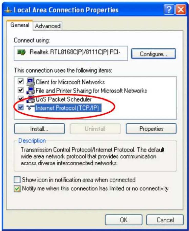
- Check "Obtain an IP address automatically" and "Obtain DNS server address automatically" then click on "OK" to continue.
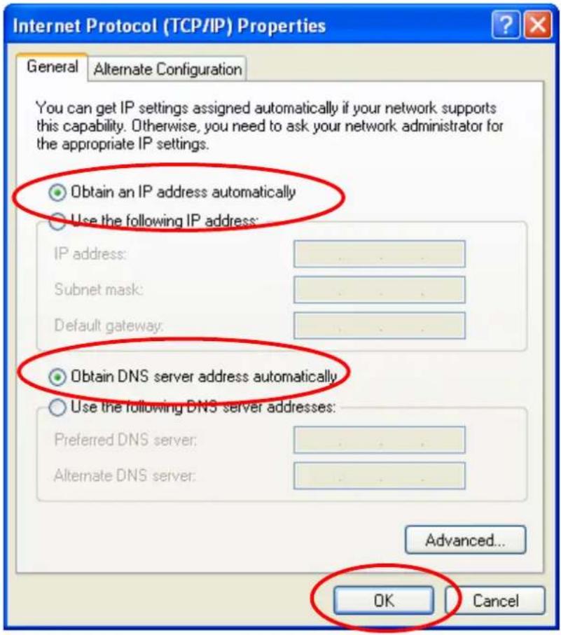
-
Click "Show icon in notification area when connected" (see screen image in 3. above) then Click on "OK" to complete the setup procedures.
-
Click on "Start" -> "Control Panel" -> "View network status and tasks".

- In the Manage network connections, click on "Manage network connections" to continue.

- Single RIGHT click on "Local Area connection", then click "Properties".
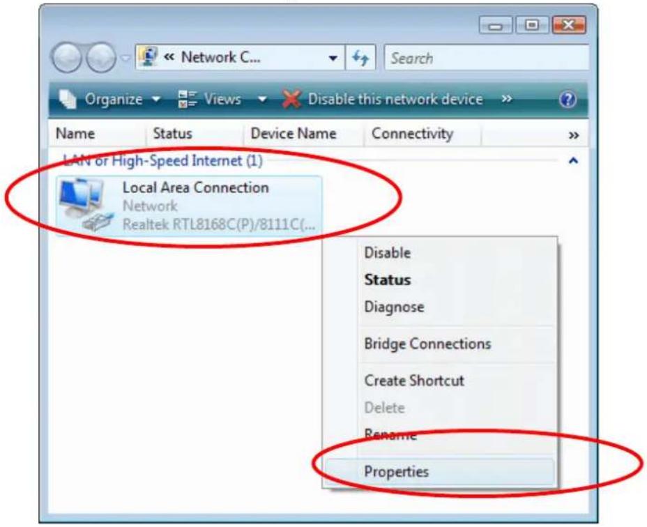
- The screen will display the information "User Account Control" and click "Continue" to continue.
- Double click on "Internet Protocol Version 4 (TCP/IPv4)".
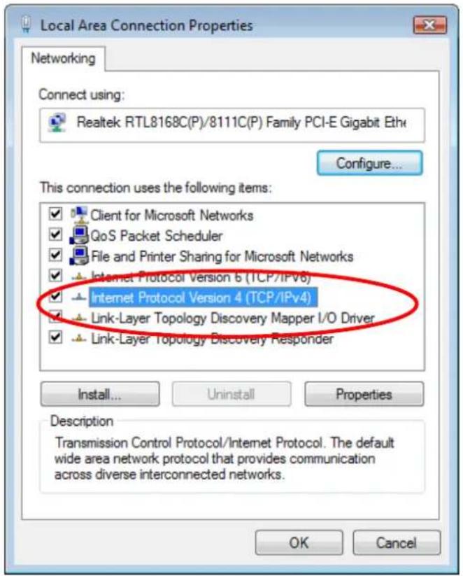
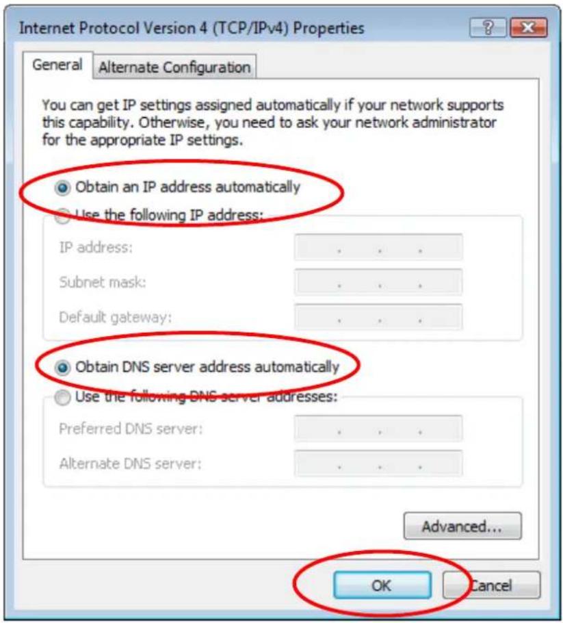
- Check "Obtain an IP address automatically" and "Obtain DNS server address automatically" then click on "OK" to continue.
For Windows 7-32/64
- Click on "Start" -> "Control Panel" (in Category View) -> "View network status and tasks".

- In the Control Panel Home, click on "Change adapter settings" to continue.
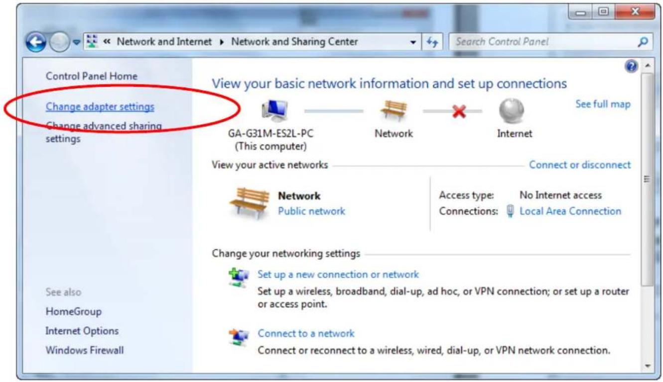
- Single RIGHT click on "Local Area Connection", then click "Properties".

- Double click on "Internet Protocol Version 4 (TCP/IPv4)".

- Check "Obtain an IP address automatically" and "Obtain DNS server address automatically" then click on "OK" to continue.

- Move the mouse or tap to the upper right corner and click on "Settings".
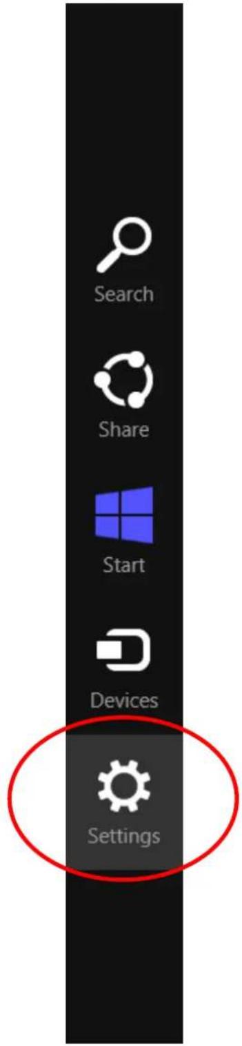
- Click on "Control Panel".
Settings
Desktop
Control Panel
Personalisation
PC info
Help

Unavailable

100

Unavailable

Notifications

Power

Keyboard
Change PC settings
- Click on "View network status and tasks".

- In the Control Panel Home, click on "Change adapter settings" to continue.
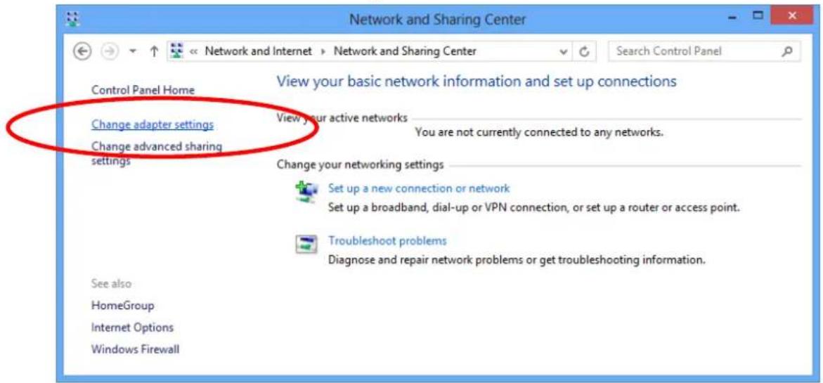
- Single RIGHT click on "Ethernet", then click "Properties".

- Double click on "Internet Protocol Version 4 (TCP/IPv4)".

- Check "Obtain an IP address automatically" and "Obtain DNS server address automatically" then click on "OK" to continue.

- Right click on Network icon, then click "Open Network and Sharing Center".
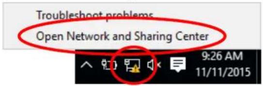
- In the Control Panel Home, click on "Change adapter settings" to continue.

3. Single RIGHT click on "Ethernet", then click "Properties".

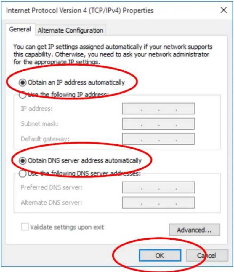
- Double click on "Internet Protocol Version 4 (TCP/IPv4)".

- Check "Obtain an IP address automatically" and "Obtain DNS server address automatically" then click on "OK" to continue.
4 Connecting your device
This chapter provides basic instructions for connecting the Portable Repeater to a computer or LAN and to the Internet.
In addition to configuring the device, you need to configure the Internet properties of your computer(s). For more details, see the following sections:
- Configuring Ethernet PCs
This chapter assumes that you have already established a DSL/Cable service with your Internet service provider (ISP). These instructions provide a basic configuration that should be compatible with your home or small office network setup. Refer to the subsequent chapters for additional configuration instructions.
Connecting the Hardware
This section describes how to connect the device to the wall phone port, the power outlet and your computer(s) or network.

Before you begin, turn the power off for all devices. These include your computer(s), your LAN hub/switch (if applicable), and the Portable Repeater.
The diagram below illustrates the hardware connections. The layout of the ports on your device may vary from the layout shown. Refer to the steps that follow for specific instructions.
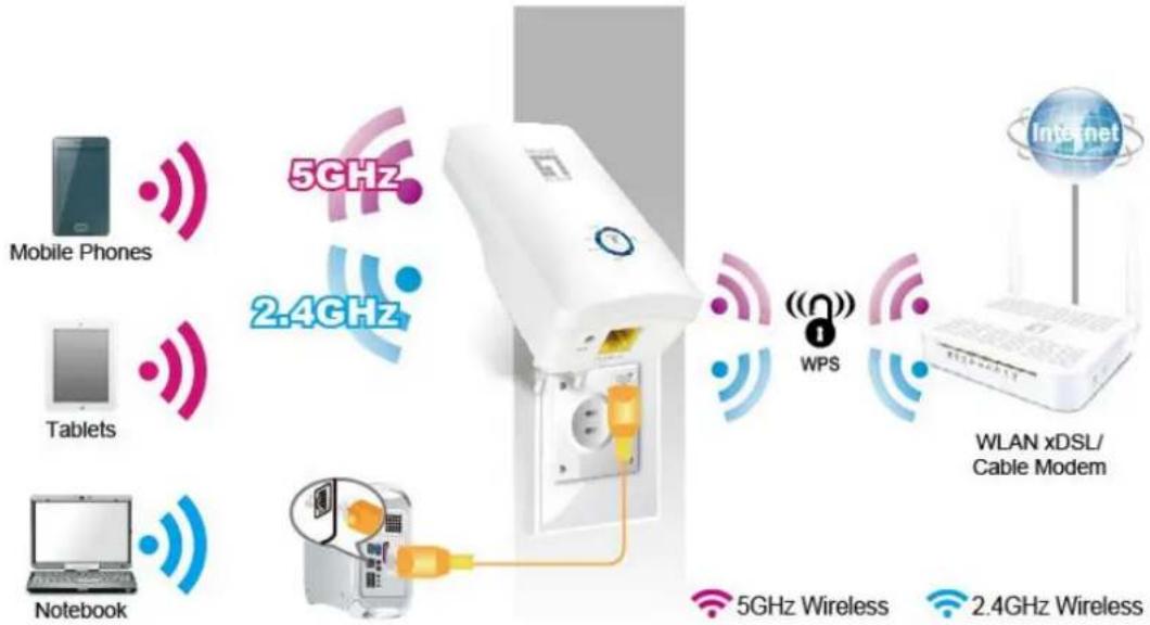
Step 1. Connect the Ethernet cable to LAN Port Connect the supplied RJ45 Ethernet cable from your PC's Ethernet port to any of the WRE-8011E LAN Port.
Step 2. Connect the WRE-8011E to your wall-mounted power outlet
WPS Pairing between WRE-8011E and Wireless xDSL/Cable Modem
This section describes how to do WPS Pairing between WRE-8011E and Wireless xDSL/Cable.
The diagram below illustrates the hardware connections. The layout of the ports on your device may vary from the layout shown. Refer to the steps that follow for specific instructions.

Step 1. Press WPS button on Wireless xDSL/Cable Modem.
Step 2. Press WPS button on WRE-8011E for 3 seconds and release WPS button. Now the WPS LED is blinking and the WRE-8011E is donig WPS Pairing with Wireless xDSL/Cable Modem.
Make sure to press the button within 120 seconds (2 minutes) after pressing the Wireless xDSL/Cable Modem's WPS button.
Step 3. Once the WRE-8011E finished doing WPS Pairing with Wireless xDSL/Cable Modem, the Wifi Signal Strength LED is ON. The status of Wifi signal strength LED varies depending on the Wifi signal strength between WRE-8011E and Wireless xDSL/Cable Modem.
Step 4. Check if the Wifi Signal Strength LED of WRE-8011E is ON, the WRE-8011E is connected and suitable for Internet Connections.
Step 5. Check if the Wifi Signal Strength is OFF, the WRE-8011E isn't connected and suitable for Internet Connections. Please repeat steps of WPS Pairing or follow next step to have it connected and suitable for Internet Connections.
5 Advanced Configuration
Advanced Configuration
- From any of the LAN computers connected to, launch your web browser, type the following URL in the web address (or location) box, and press [Enter] on your keyboard: http://repeater.nw
Repeater Mode (Extend your Wireless Network)
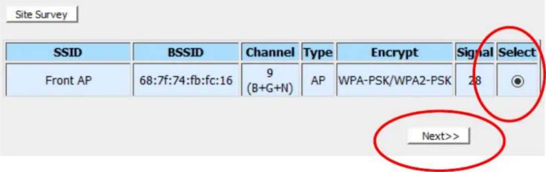
- Check on "Select" ratio of SSID of the front AP and click on "Next>>" button.
Wireless Site Survey
This page provides tool to scan the wireless network. If any Access Point or IBSS is found, you could choose to connect it manually when client mode is enabled.
- Enter Wifi password of the front AP and then click on "Connect" button.
Wireless Site Survey
This page provides tool to scan the wireless network. If any Access Point or IBSS is found, you could choose to connect it manually when client mode is enabled.

LAN Interface Setup
This page is used to configure the parameters for local area network which connects to the LAN port of your Access Point. Here you may change the setting for IP address, subnet mask, DHCP, etc..  8. Change setting successfully! Do not turn off or reboot the Device during this time. Please wait 20 seconds ... Change setting successfully! Do not turn off or reboot the Device during this time. Please wait 19 seconds ... 9. Please disconnect the Ethernet Cable from PC and connect it to the LAN port of xDSL/Cable Modem. 10. Please wait for 2 minutes. 11. Now, the WRE-8011E has been configured completed, and suitable for Wireless and Internet Connections.Wireless Connection
For easy installation it is saved to keep the settings. You can later change the wireless settings via the wireless configuration menu. 1. Double click on the network icon on your computer and search for the wireless network that you enter SSID name. 2. Click on the wireless network that you enter SSID name (the default settings, Wireless Network = Enable, Default Channel = Auto, SSID = LevelOne 5G for 5GHz and LevelOne 2.4G for 2.4GHz) to connect.  3. If the wireless network isn't encrypted, click on "Connect" to connect.   4. If the wireless network is encrypted, enter your own wireless password at least 8 characters for example 12345678 in the key field / Network key field / Confirm Network key field (the default settings Security Mode = None). You can later change this network key via the wireless configuration menu. 5. Click on "Next".   6. Now you are ready to use the Wireless Network to Internet or intranet.6 What the Internet/WAN access of your own Network now is
Now you could check what the Internet/WAN access of your network is to know how to configure the WAN port of Portable Repeater. Please follow steps below to check what the Internet/WAN access if your own Network is DHCP Client, Static IP or PPPoE Client. 1. Click Start -> Control Panel  2. Double click Network Connections Internet/WAN access is the DHCP client
If you cannot see any Broadband Adapter in the Network Connections, your Internet/WAN access is DHCP Client or Static IP. 3. Click Local Area Connection in LAN or High-Speed Internet and you could see string Assigned by DHCP in Details. Internet/WAN access is the Static IP
If you cannot see any Broadband Adapter in the Network Connections, your Internet/WAN access is DHCP Client or Static IP. 4. Click Local Area Connection in LAN or High-Speed Internet and you could see string Manually Configured in Details.  5. Right click Local Area Connection and click Properties and then you could get the IP settings in detail and write down the IP settings as follow: IP Address: 192.168.10.110 Subnet mask: 255.255.255.0 Default gateway: 192.168.10.100 Preferred DNS server: 192.168.10.100 Alternate DNS Server: If you have it, please also write it down. Internet/WAN access is the PPPoE client
If you can see any Broadband Adapter in the Network Connections, your Internet/WAN access is PPPoE Client. 6. Click Broadband Adapter in Broadband and you could see string Assigned by Service Provider in Details. For PPPoE configuration on Portable Repeater, you'll need following information that you could get from your Telecom, or by your Internet Service Provider. Username of PPPoE: 1234 for example Password of PPPoE: 1234 for example 7 Getting Started with the Web pages
The Portable Repeater includes a series of Web pages that provide an interface to the software installed on the device. It enables you to configure the device settings to meet the needs of your network. You can access it through your web browser from any PC connected to the device via the LAN ports.Accessing the Web pages
To access the Web pages, you need the following: \- A PC or laptop connected to the LAN port on the device. \- A web browser installed on the PC. The minimum browser version requirement is Internet Explorer v4 or Netscape v4. For the best display quality, use latest version of Internet Explorer, Netscape or Mozilla Fire fox. From any of the LAN computers, launch your web browser, type the following URL in the web address (or location) box, and press [Enter] on your keyboard: http://repeater.nw The Quick Setup homepage for the web pages is displayed:  Figure 2: Homepage 1. You are now ready to configure your device. This is the first page displayed each time you log in to the Web pages.  Note If you receive an error message or the Welcome page is not displayed, see Troubleshooting Suggestions.Testing your Setup
Once you have connected your hardware and configured your PCs, any computer on your LAN should be able to use the DSL/Cable connection to access the Internet. To test the connection, turn on the device, wait for 30 seconds and then verify that the LEDs are illuminated as follows: Table 1. LED Indicators| Label | Color | Function |
| POWER | green | On: device is powered onOff: device is powered off |
| WLAN | green | On: WLAN link established and activeBlink: Valid Wireless packet being transferred |
| LAN | green | On: LAN link established and activeOff: No LAN linkBlink: Valid Ethernet packet being transferred |
Default device settings
In addition to handling the xDSL / Cable modem connection to your ISP, the Portable Repeater can provide a variety of services to your network. The device is preconfigured with default settings for use with a typical home or small office network. The table below lists some of the most important default settings; these and other features are described fully in the subsequent chapters. If you are familiar with network configuration, review these settings to verify that they meet the needs of your network. Follow the instructions to change them if necessary. If you are unfamiliar with these settings, try using the device without modification, or contact your ISP for assistance. WARNING
We strongly recommend that you contact your ISP prior to changing the default configuration.| Option | Default Setting | Explanation/Instructions |
| WAN Port IP Address | DHCP Client | This is the temporary public IP address of the WAN port on the device. It is an unnumbered interface that is replaced as soon as your ISP assigns a ‘real’ IP address. See Network Settings -> WAN Interface. |
| LAN Port IP Address | Assigned static IP address: 192.168.1.1 Subnet mask: 255.255.255.0 | This is the IP address of the LAN port on the device. The LAN port connects the device to your Ethernet network. Typically, you will not need to change this address. See Network Settings -> LAN Interface. |
| DHCP (Dynamic Host Configuration Protocol) | DHCP server enabled with the following pool of addresses: 192.168.1.100 through 192.168.1.200 | The Portable Repeater maintains a pool of private IP addresses for dynamic assignment to your LAN computers. To use this service, you must have set up your computers to accept IP information dynamically, as described in Configuring Ethernet PCs. |
8 Quick Setup
The Quick Setup page displays useful information about the setup of your device, including: - details of the device's Internet access settings • details of the device's VoIP settings - details of the device's Wireless settings To display this page: From the head menu, click on Setup. The following page is displayed:Wireless Site Survey
This page provides tool to scan the wireless network. If any Access Point or IBSS is found, you could choose to connect it manually when client mode is enabled. Site Survey| SSID | BSSID | Channel | Type | Encrypt | Signal | Select |
| Front AP | 68:7f:74:fb:fc:16 | 9(B+G+N) | AP | WPA-PSK/WPA2-PSK | 38 |
Repeater Mode (Extend your Wireless Network)
1. Check on "Select" ratio of SSID of the front AP and click on "Next>>" button.Wireless Site Survey
This page provides tool to scan the wireless network. If any Access Point or IBSS is found, you could choose to connect it manually when client mode is enabled. Site Survey| SSID | BSSID | Channel | Type | Encrypt | Signal | Select |
| Front AP | 68:7f:74:fb:fc:16 | 9 (B+G+N) | AP | WPA- PSK/WPA2- PSK | 38 | |
| Next>> |
Wireless Site Survey
This page provides tool to scan the wireless network. If any Access Point or IBSS is found, you could choose to connect it manually when client mode is enabled. Encryption: WPA-MIXED Authentication Mode: WPA Cipher Suite: WPA2 Cipher Suite: Pre-Shared Key Format: Pre-Shared Key: ○ Enterprise (RADIUS) ● Personal (Pre-Shared Key) √ TKIP √ AES TKIP AES Passphrase <-
Click on "Reboot Now" button.
-
Change setting successfully! Do not turn off or reboot the Device during this time. Please wait 20 seconds ...
Change setting successfully!
Do not turn off or reboot the Device during this time.
Please wait 19 seconds ...
AP Mode (Extend your Wired Network to allow wireless devices to connect your wired network using Wi-Fi)
- Click on "TCP/IP Settings -> LAN SETTING" from left menu.
![graph LR A["WLAN Access Points"] --> B["SETUP"] B --> C["WLAN1"] C --> D["WLAN2"] D --> E["TCP/IP"] E --> F["MANAGEMENT"] G["LAN SETTING"] --> H["Red Box"] style A fill:#f9f,stroke:#333 style G fill:#9cf,stroke:#333](/content/2026/07/1416435/images/92869c2a6b9b2d38f02ba559382b8924746cbc99df212d3c8ddc87631650daa1.jpg)
- Select on "Client" from DHCP drop-down list.
- Click on "Save & Apply" button.
LAN Interface Setup
This page is used to configure the parameters for local area network which connects to the LAN port of your Access Point. Here you may change the setting for IP address, subnet mask, DHCP, etc..

- Change setting successfully! Do not turn off or reboot the Device during this time. Please wait 20 seconds ...
Change setting successfully!
Do not turn off or reboot the Device during this time.
Please wait 19 seconds ...
-
Please disconnect the Ethernet Cable from PC and connect it to the LAN port of xDSL/Cable Modem.
-
Now, the WRE-8011E has been configured completed, and suitable for Wireless and Internet Connections.
9 LAN Interface
This chapter is to configure the parameters for local area network which connects to the LAN port of your Access Point. Here you may change the setting for IP address, subnet mask, DHCP, etc...

Note
You should only change the addressing details if your ISP asks you to, or if you are familiar with network configuration. In most cases, you will not need to make any changes to this configuration.
LAN Interface Setup
To check the configuration of LAN Interface:
- From the left-hand menu, click on TCP/IP Settings -> LAN SETTING. The following page is displayed:
LAN Interface Setup
This page is used to configure the parameters for local area network which connects to the LAN port of your Access Point. Here you may change the setting for IP address, subnet mask, DHCP, etc..
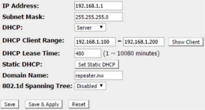
| Field | Description |
| IP Address | The IP address of your router on the local area network. Your local area network settings are based on the address assigned here. |
| Subnet Mask | The subnet mask of your router on the local area network. |
| DHCP Mode | Once your router is properly configured and DHCP Server is enabled, the DHCP Server will manage the IP addresses and other network configuration information for computers and other devices connected to your Local Area Network. There is no need for you to do this yourself.The computers (and other devices) connected to your LAN also need to have their TCP/IP configuration set to "DHCP" or "Obtain a IP address automatically". |
| IP Pool Range | These two IP values (from and to) define a range of IP addresses that the DHCP Server uses when assigning addresses to computer and devices on your Local Area Network. Any addresses that are outside of this range are not managed by the DHCP Server; these could, therefore, be used for manually configured devices or devices that cannot use DHCP to obtain network address details automatically.Your router, by default, has a static IP address of 192.168.0.1. This means that addresses 192.168.0.2 to 192.168.0.254 can be made available for allocation by the DHCP Server. |
| Max Lease Time | The amount of time that a computer may have an IP address before it is required to renew the lease. The lease functions just as a lease on an apartment would. The initial lease designates the amount of time before the lease expires. If the tenant wishes to retain the address when the lease is expired then a new lease is established. the lease expires and the address is no longer needed then another tenant may use the address. |
| Domain Name | Domain name for the dhcp server scope. |
| IP Address | The IP address to be configured for your computer or device on the local area network.For example, 192.168.0.2. |
| Mac Address | The mac address of your computer or device on the local area network. |
Changing the LAN IP address and subnet mask
To Change the configuration of LAN Interface:
- From the left-hand menu, click on TCP/IP Settings -> LAN Interface. The following page is displayed:
LAN Interface Setup
This page is used to configure the parameters for local area network which connects to the LAN port of your Access Point. Here you may change the setting for IP address, subnet mask, DHCP, etc..
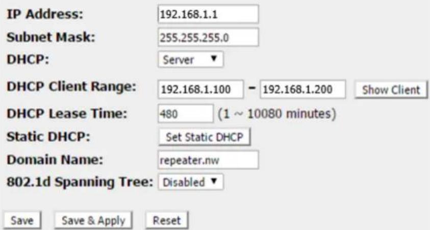
- Change the IP Address and Subnet Mask and DHCP Client Range.
- Click Save & Apply.
LAN Interface Setup
This page is used to configure the parameters for local area network which connects to the LAN port of your Access Point. Here you may change the setting for IP address, subnet mask, DHCP, etc..
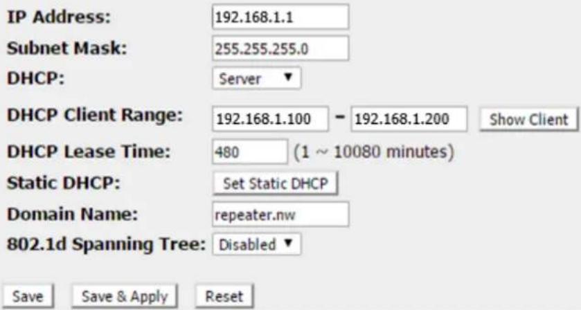
- Change setting successfully! Do not turn off or reboot the Device during this time. Please wait 15 seconds ....
Change setting successfully! Do not turn off or reboot the Device during this time. Please wait 24 seconds ...
You may also need to renew your DHCP lease:
Windows 95/98
a. Select Run... from the Start menu.
b. Enter winipcfg and click OK.
c. Select your ethernet adaptor from the pull-down menu
d. Click Release All and then Renew All.
e. Exit the winipcfg dialog.
Windows NT/Windows 2000/Windows XP
a. Bring up a command window.
b. Type ipconfig /release in the command window.
c. Type ipconfig /renew.
d. Type exit to close the command window.
Linux
a. Bring up a shell.
b. Type pump -r to release the lease.
c. Type pump to renew the lease.

Note
If you change the LAN IP address of the device while connected through your Web browser, you will be disconnected. You must open a new connection by entering your new LAN IP address as the URL.
DHCP Static IP Configuration
If you need to assign static ip for your computer or device on the local area network, configure static ip with the mac address.:
- From the left-hand menu, click on TCP/IP Settings -> LAN Interface. The following page is displayed:
- Click Set Static DHCP
LAN Interface Setup
This page is used to configure the parameters for local area network which connects to the LAN port of your Access Point. Here you may change the setting for IP address, subnet mask, DHCP, etc..
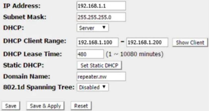
- Enable Static DHCP.
- Enter the IP Address.
- Enter the Mac Address.
- Click Add.
Static DHCP Setup
This page allows you reserve IP addresses, and assign the same IP address to the network device with the specified MAC address any time it requests an IP address. This is almost the same as when a device has a static IP address except that the device must still request an IP address from the DHCP server.
√ Enable Static DHCP

Apply Changes
Reset
7. Click Reboot Now.
Change setting successfully!
Your changes have been saved. The router must be rebooted for the changes to take effect. You can reboot now, or you can continue to make other changes and reboot later.
Reboot Now
Reboot Later
- The DHCP Static IP Configuration that you created has been added in the DHCP Static IP Table.
Static DHCP List:
| IP Address | MAC Address | Comment | Select |
| 192.168.1.200 | 00-24-1d-1d-cf-cd | 00241D1DCFCD |
Delete Selected
Delete All
Reset
10 Wireless Network - 5GHz
This chapter assumes that you have already set up your Wireless PCs and installed a compatible Wireless card on your device. See Configuring Wireless PCs.
Wireless Basics
The Wireless Network page allows you to configure the Wireless features of your device. To access the Wireless Basics page:
From the Wireless menu, click on WLAN1 -> BASIC SETTING. The following page is displayed:
Wireless Basic Settings -5G
This page is used to configure the parameters for wireless LAN clients which may connect to your Access Point. Here you may change wireless encryption settings as well as wireless network parameters.

Disable Wireless LAN Interface
Band:
5 GHz (A+N+AC) ▼
Mode:
AP ▼
MultipleAP
Network Type:
Infrastructure ▼
SSID:
LevelOne 5
Add to Profile
Channel Width:
80MHz ▼
Control
Sideband:
Auto ▼
Channel
Number:
Auto ▼
Broadcast
Enabled
SSID:
WMM:
Enabled
Data Rate:
Auto
TX restrict:
0
Mbps (0:no restrict)
RX restrict:
0
Mbps (0:no restrict)
Associated
Clients:
Show Active Clients

Enable Universal Repeater Mode (Acting as AP and not simultaneously)
SSID of Extended Interface:
RTK 11n AP RPT0
Add to Profile

Enable Wireless Profile
Wireless Profile List:
| SSID | Encrypt | Select | |
| Delete Selected | DeleteAll | ||
Figure 4: Wireless Network page
| Field | Description |
| Disable Wireless LAN Interface | Enable/Disable the Wireless LAN Interface.Default: Disable |
| Band | Specify the WLAN Mode to 802.11b/g Mixed mode, 802.11b mode or 802.11g mode |
| Mode | Configure the Wireless LAN Interface to AP, Client, WDS, AP + WDS, MESH or AP + MESH mode |
| Network Type | Configure the Network Type to Infrastructure or Ad hoc. |
| SSID | Specify the network name.Each Wireless LAN network uses a unique Network Name to identify the network. This name is called the Service Set Identifier (SSID). When yo set up your wireless adapter, you specify the SSID. If you want to connect to an existing network, you must use the name for that network. If you are setting up your own network you can make up your own name and use it on each computer. The name can be up to 20 characters long and contain letters and numbers. |
| Channel Width | Choose a Channel Width from the pull-down menu. |
| Control Sideband | Choose a Control Sideband from the pull-down menu. |
| Channel Number | Choose a Channel Number from the pull-down menu. |
| Broadcast SSID | Broadcast or Hide SSID to your Network.Default: Enabled |
| WMM | Enable/disable the Wi-Fi Multimedia (WMM) support. |
| Data Rate | Select the Data Rate from the drop-down list |
| Associated Clients | Show Active Wireless Client TableThis table shows the MAC address, transmission, reception packet counters and encrypted status for each associated wireless client. |
| Enable Mac Clone (Single Ethernet Client) | Enable Mac Clone (Single Ethernet Client) |
| Enable Universal Repeater Mode | Acting as AP and client simultaneously |
| SSID of Extended Interface | When mode is set to “AP” and URM (Universal Repeater Mode) is enabled, user should input SSID of another AP in the field of “SSID of Extended Interface”. Please note, the channel number should be set to the one, used by another AP because 8186 will share the same channe between AP and URM interface (called as extended interface hereafter) |
Advanced Settings
These settings are only for more technically advanced users who have a sufficient knowledge about wireless LAN. These settings should not be changed unless you know what effect the changes will have on your Access Point. To access the Wireless Network Advanced Settings page:
From the left-hand Wireless menu, click on WLAN1 -> Advanced Settings. The following page is displayed:
Wireless Advanced Settings -5G
These settings are only for more technically advanced users who have a sufficient knowledge about wireless LAN. These settings should not be changed unless you know what effect the changes will have on your Access Point.
| Fragment Threshold: | 2346 | (256-2346) |
| RTS Threshold: | 2347 | (0-2347) |
| Beacon Interval: | 100 | (20-1024 ms) |
| IAPP: | ● Enabled | ○ Disabled |
| Protection: | ○ Enabled | ● Disabled |
| Aggregation: | ● Enabled | ○ Disabled |
| Short GI: | ● Enabled | ○ Disabled |
| WLAN Partition: | ○ Enabled | ● Disabled |
| STBC: | ● Enabled | ○ Disabled |
| LDPC: | ● Enabled | ○ Disabled |
| TX Beamforming: | ● Enabled | ○ Disabled |
| MU MIMO: | ○ Enabled | ● Disabled |
| Mutilcast to Unicast: | ● Enabled | ○ Disabled |
| TDLS Prohibited: | ○ Enabled | ● Disabled |
| TDLS Channel Switch Prohibited: | ○ Enabled | ● Disabled |
| RF Output Power: | ● 100% | ○ 70% ○ 50% ○ 35% ○ 15% |
| Field | Description |
| Fragment Threshold | When transmitting a packet over a network medium, sometimes the packet is broken into several segments, if the size of packet exceeds that allowed by the network medium.The Fragmentation Threshold defines the number of bytes used for the fragmentation boundary for directed messages. |
| RTS Threshold | RTS stands for “Request to Send”. This parameter controls what size data packet the low level RF protocol issues to an RTS packet. The default is 2347. |
| Beacon Interval | Choosing beacon period for improved response time for wireless http clients. |
| Preamble Type | Specify the Preamble type is short preamble or long preamble |
| IAPP | Disable or Enable IAPP |
| Protection | A protection mechanism prevents collisions among 802.11g nodes. |
| Aggregation | Disable or Enable Aggregation |
| Short GI | Disable or Enable Short GI |
| WLAN Partition | Disable or Enable WLAN Partition |
| STBC | Disable or Enable STBC |
| 20/40MHz Coexist | Disable or Enable 20/40MHz Coexist |
| RF Output Power | TX Power measurement. |
Security
This page allows you setup the wireless security. Turn on WEP or WPA by using Encryption Keys could prevent any unauthorized access to your wireless network. To access the Wireless Network Security page:
From the left-hand Wireless menu, click on WLAN1 -> Security. The following page is displayed:
Wireless Security Setup -wlan1 Wireless Security Setup -5G
This page allows you setup the wireless security. Turn on WEP or WPA by using Encryption Keys could prevent any unauthorized access to your wireless network.
Select SSID:
Root AP - LevelOne 5G
Save
Save & Apply
Reset
Encryption:
Disable
| Field | Description |
| Select SSID | Select the SSID |
| Encryption | Configure the Encryption to Disable, WEP, WPA , WPA2 or WPA-Mixed |
| Use 802.1x Authentication | Use 802.1x Authentication by WEP 64bits or WEP 128bits |
| Authentication | Configure the Authentication Mode to Open System, Shared Key or Auto |
| Key Length | Select the Key Length 64-bit or 128-bit |
| Key Format | Select the Key Format ASCII (5 characters), Hex (10 characters), ASCII (13 characters) or Hex (26 characters) |
| Encryption Key | Enter the Encryption Key |
| WPA Authentication Mode | Configure the WPA Authentication Mode to Enterprise (RADIUS) or Personal (Pre-Shared Key) |
| WPA Cipher Suite | Configure the WPA Cipher Suite to AES |
| Field | Description |
| WPA2 Cipher Suite | Configure the WPA2 Cipher Suite to AES |
| Pre-Shared Key | Configure the Pre-Shared Key Format to Passphrase or HEX (64) |
| Format | characters) |
| Pre-Shared Key | Type the Pre-Shared Key |
| Enable Pre-Authentication | According to some of the preferred embodiments, a method for proactively establishing a security association between a mobile node in a visiting network and an authentication agent in another network to which the mobile node can move includes: negotiating pre-authentication using a flag in a message header that indicates whether the communication is for establishing a pre-authentication security association; and one of the mobile node and the authentication agent initiating pre-authentication by transmitting a message with the flag se in its message header, and the other of the mobile node and the authentication agent responding with the flag set in its message heade only if it supports the pre-authentication. Enable/disable pre-authentication support. Default: disable. |
| Authentication RADIUS Server | Port: Type the port number of RADIUS ServerIP address: Type the IP address of RADIUS ServerPassword: Type the Password of RADIUS Server |
WEP + Encryption Key
WEP aims to provide security by encrypting data over radio waves so that it is protected as it is transmitted from one end point to another. However, it has been found that WEP is not as secure as once believed.
- From the Encryption drop-down list, select WEP setting.
- From the Key Length drop-down list, select 64-bit or 128-bit setting.
- From the Key Format drop-down list, select ASCII (5 characters), Hex (10 characters), ASCII (13 characters) or Hex (26 characters) setting.
- Enter the Encryption Key value depending on selected ASCII or Hexadecimal.
- Click Save & Apply button.
Wireless Security Setup -wlan1 Wireless Security Setup -5G
This page allows you setup the wireless security. Turn on WEP or WPA by using Encryption Keys could prevent any unauthorized access to your wireless network.

- Click OK button.

- Change setting successfully! Do not turn off or reboot the Device during this time. Please wait 20 seconds ...
Change setting successfully!
Do not turn off or reboot the Device during this time.
Please wait 19 seconds ...
WEP + Use 802.1x Authentication
WEP aims to provide security by encrypting data over radio waves so that it is protected as it is transmitted from one end point to another. However, it has been found that WEP is not as secure as once believed.
- From the Encryption drop-down list, select WEP setting.
- Check the option of Use 802.1x Authentication.
- Click on the ratio of WEP 64bits or WEP 128bits.
- Enter the Port, IP Address and Password of RADIUS Server:

- Click Save & Apply button.
Wireless Security Setup -5G
This page allows you to setup the wireless security. Tum on WEP or WPA by using Encryption Keys could prevent any unauthorized access to your wireless network.

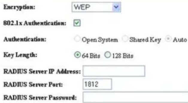
6. Click OK button.
go.microsoft.com says:
if WEP is turn on, WPS2.0 will be disabled
OK
Cancel
7. Change setting successfully! Do not turn off or reboot the Device during this time. Please wait 20 seconds ...
Change setting successfully!
Do not turn off or reboot the Device during this time.
Please wait 19 seconds ...
WPA2/WPA Mixed + Personal (Pre-Shared Key)
Wi-Fi Protected Access (WPA and WPA2) is a class of systems to secure wireless (Wi-Fi)
computer networks. WPA is designed to work with all wireless network interface cards, but not necessarily with first generation wireless access points. WPA2 implements the full standard, but will not work with some older network cards. Both provide good security, with two significant issues:
- Either WPA or WPA2 must be enabled and chosen in preference to WEP. WEP is usually presented as the first security choice in most installation instructions.
- In the "Personal" mode, the most likely choice for homes and small offices, a pass phrase is required that, for full security, must be longer than the typical 6 to 8 character passwords users are taught to employ.
1. From the Encryption drop-down list, select WPA2 or WPA Mixed setting.

2. Click on the ratio of Personal (Pre-Shared Key).
Authentication Mode: ○ Enterprise (RADIUS) ● Personal (Pre-Shared Key)
3. Check the option of AES in WPA2 Cipher Suite if your Encryption is WPA2:
WPA2 Cipher Suite: □ TKIP √ AES
- Check the option of TKIP and/or AES in WPA/WPA2 Cipher Suite if your Encryption is WPA Mixed:
| WPA Cipher Suite: | TKIP | AES |
| WPA2 Cipher Suite: | TKIP | AES |
- From the Pre-Shared Key Format drop-down list, select Passphrase or Hex (64 characters) setting.
| Pre-Shared Key Format: | Passphrase |
| Pre-Shared Key Format: | HEX (64 characters) |
- Enter the Pre-Shared Key depending on selected Passphrase or Hex (64 characters).
Pre-Shared Key:
- Click on Save & Apply button to confirm and return.
Save & Apply
- Change setting successfully! Do not turn off or reboot the Device during this time. Please wait 20 seconds ...
Change setting successfully! Do not turn off or reboot the Device during this time. Please wait 19 seconds ...
WPA2/WPA Mixed + Enterprise (RADIUS)
Wi-Fi Protected Access (WPA and WPA2) is a class of systems to secure wireless (Wi-Fi) computer networks. WPA is designed to work with all wireless network interface cards, but not necessarily with first generation wireless access points. WPA2 implements the full standard, but will not work with some older network cards. Both provide good security, with two significant issues:
- Either WPA or WPA2 must be enabled and chosen in preference to WEP. WEP is usually presented as the first security choice in most installation instructions.
-
In the "Personal" mode, the most likely choice for homes and small offices, a pass phrase is required that, for full security, must be longer than the typical 6 to 8 character passwords users are taught to employ.
-
From the Encryption drop-down list, select WPA2 or WPA Mixed setting.
| Encryption: | WPA2 |
| Encryption: | WPA-Mixed |
- Click on the ratio of Enterprise (RADIUS).
Authentication Mode: ● Enterprise (RADIUS) ○ Personal (Pre-Shared Key)
- Check the option of AES in WPA2 Cipher Suite if your Encryption is WPA2:
WPA2 Cipher Suite: □ TKIP √ AES
- Check the option of TKIP and/or AES in WPA/WPA2 Cipher Suite if your Encryption is WPA Mixed:
WPA Cipher Suite: ☑ TKIP ☑ AES WPA2 Cipher Suite: ☑ TKIP ☑ AES
- Enter the Port, IP Address and Password of RADIUS Server:
RADIUS Server IP Address:
RADIUS Server Port: 1812
RADIUS Server Password:
- Click on Save & Apply button to confirm and return.
Save & Apply
- Change setting successfully! Do not turn off or reboot the Device during this time. Please wait 20 seconds ...
Change setting successfully! Do not turn off or reboot the Device during this time. Please wait 19 seconds ...
Wireless Access Control Mode
For security reason, using MAC ACL's (MAC Address Access List) creates another level of difficulty to hacking a network. A MAC ACL is created and distributed to AP so that only authorized NIC's can connect to the network. While MAC address spoofing is a proven means to hacking a network this can be used in conjunction with additional security measures to increase the level of complexity of the network security decreasing the chance of a breach.
MAC addresses can be add/delete/edit from the ACL list depending on the MAC Access Policy.
If you choose 'Allowed Listed', only those clients whose wireless MAC addresses are in the access control list will be able to connect to your Access Point. When 'Deny Listed' is selected, these wireless clients on the list will not be able to connect the Access Point. To access the Wireless Network Access Control page:
From the left-hand Wireless menu, click on WLAN1 -> Access Control. The following page is displayed:
Wireless Access Control -5G
If you choose 'Allowed Listed', only those clients whose wireless MAC addresses are in the access control list will be able to connect to your Access Point. When 'Deny Listed' is selected, these wireless clients on the list will not be able to connect the Access Point.
Wireless Access Control Mode:
Disable

MAC Address:
Comment:
Save
Save & Apply
Reset
Current Access Control List:
MAC Address
Comment
Select
Delete Selected
Delete All
Reset
Allow Listed
If you choose 'Allowed Listed', only those clients whose wireless MAC addresses are in the access control list will be able to connect to your Access Point.
- From the Wireless Access Control Mode drop-down list, select Allowed Listed setting.
- Enter the MAC Address.
- Enter the Comment.
- Click Save & Apply button.

- Click OK button.
Message from webpage


if ACL allow list turn on; WPS2.0 will be disabled

- Change setting successfully! Do not turn off or reboot the Device during this time. Please wait 20 seconds ...
Change setting successfully!
Do not turn off or reboot the Device during this time.
Please wait 19 seconds ...
- The MAC Address that you created has been added in the Current Access Control List.
Current Access Control List:
| MAC Address | Comment | Select | ||
| 00:11:22:33:44:55 | 001122334455 | |||
| Delete Selected | Delete All | Reset | ||
Deny Listed
When 'Deny Listed' is selected, these wireless clients on the list will not be able to connect the Access Point.
- From the Wireless Access Control Mode drop-down list, select Deny Listed setting.
- Enter the MAC Address.
- Enter the Comment.
- Click Save & Apply button.

- Change setting successfully! Do not turn off or reboot the Device during this time. Please wait 20 seconds ...
Change setting successfully! Do not turn off or reboot the Device during this time. Please wait 19 seconds ...
WPS
This page allows you to change the setting for WPS (Wi-Fi Protected Setup). Using this feature could let your wireless client automatically synchronize its setting and connect to the Access Point in a minute without any hassle. To access the Wireless Network WPS page:
From the left-hand Wireless menu, click on WLAN1 -> WPS. The following page is displayed:
Wi-Fi Protected Setup
This page allows you to change the setting for WPS (Wi-Fi Protected Setup). Using this feature could let your wireless client automatically synchronize its setting and connect to the Access Point in a minute without any hassle.

Disable WPS
Apply Changes
Reset
WPS Status:
Auto-lock-down state: unlocked
Self-PIN Number:
Push Button Configuration:
STOP WSC
Client PIN Number:
Current Key Info:
| Authentication | Encryption | Key |
| Open | None | N/A |

Configured
UnConfigured
Reset to UnConfigured
Unlock
14169564
Start PBC
Stop WSC

Start PIN
-Virtual Client-
Self-PIN Number:
14169564
PIN Configuration:
Start PIN
Push Button Configuration:
Start PBC
Client PIN Number:
Start PIN
| Field | Description |
| Disable WPS | Checking this box and clicking “Save & Apply” will disable Wi-Fi Protected Setup. WPS is turned on by default. |
| Self-PIN Number | “Self-PIN Number” is AP’s PIN. Whenever users want to change AP’s PIN, they could click “Regenerate PIN” and then click “Save & Apply”. Moreover, if users want to make their own PIN, they could enter four digit PIN without checksum and then click “Save & Apply”. However, this would not be recommended since the registrar side needs to be supported with four digit PIN. |
| Push Button Configuration | Clicking this button will invoke the PBC method of WPS. It is only used when AP acts as a registrar. |
| Save & Apply | Whenever users want to enable/disable WPS or change AP's PIN, they need to apply this button to commit changes. |
| Reset | It restores the original values of “Self-PIN Number” and “Client PIN Number”. |
| Client PIN Number | It is only used when users want their station to join AP's network. The length of PIN is limited to four or eight numeric digits. If users enter eight digit PIN with checksum error, there will be a warning message popping up.If users insist on this PIN, AP will take it. |
11 Wireless Network - 2.4GHz
This chapter assumes that you have already set up your Wireless PCs and installed a compatible Wireless card on your device. See Configuring Wireless PCs.
Wireless Basics
The Wireless Network page allows you to configure the Wireless features of your device. To access the Wireless Basics page:
From the Wireless menu, click on WLAN2 -> BASIC SETTING. The following page is displayed:
Wireless Basic Settings -2.4G
This page is used to configure the parameters for wireless LAN clients which may connect to your Access Point. Here you may change wireless encryption settings as well as wireless network parameters.


Figure 5: Wireless Network page
| Field | Description |
| Disable Wireless LAN Interface | Enable/Disable the Wireless LAN Interface.Default: Disable |
| Band | Specify the WLAN Mode to 802.11b/g Mixed mode, 802.11b mode or 802.11g mode |
| Mode | Configure the Wireless LAN Interface to AP, Client, WDS, AP + WDS, MESH or AP + MESH mode |
| Network Type | Configure the Network Type to Infrastructure or Ad hoc. |
| SSID | Specify the network name.Each Wireless LAN network uses a unique Network Name to identify the network. This name is called the Service Set Identifier (SSID). When yo set up your wireless adapter, you specify the SSID. If you want to connect to an existing network, you must use the name for that network. If you are setting up your own network you can make up your own name and use it on each computer. The name can be up to 20 characters long and contain letters and numbers. |
| Channel Width | Choose a Channel Width from the pull-down menu. |
| Control Sideband | Choose a Control Sideband from the pull-down menu. |
| Channel Number | Choose a Channel Number from the pull-down menu. |
| Broadcast SSID | Broadcast or Hide SSID to your Network.Default: Enabled |
| WMM | Enable/disable the Wi-Fi Multimedia (WMM) support. |
| Data Rate | Select the Data Rate from the drop-down list |
| Associated Clients | Show Active Wireless Client TableThis table shows the MAC address, transmission, reception packet counters and encrypted status for each associated wireless client. |
| Enable Mac Clone (Single Ethernet Client) | Enable Mac Clone (Single Ethernet Client) |
| Enable Universal Repeater Mode | Acting as AP and client simultaneously |
| SSID of Extended Interface | When mode is set to “AP” and URM (Universal Repeater Mode) is enabled, user should input SSID of another AP in the field of “SSID of Extended Interface”. Please note, the channel number should be set to the one, used by another AP because 8186 will share the same channe between AP and URM interface (called as extended interface hereafter) |
Advanced Settings
These settings are only for more technically advanced users who have a sufficient knowledge about wireless LAN. These settings should not be changed unless you know what effect the changes will have on your Access Point. To access the Wireless Network Advanced Settings page:
From the left-hand Wireless menu, click on WLAN2 -> ADVANCED. The following page is displayed:
Wireless Advanced Settings -2.4G
These settings are only for more technically advanced users who have a sufficient knowledge about wireless LAN. These settings should not be changed unless you know what effect the changes will have on your Access Point.
| Fragment Threshold: | 2346 | (256-2346) |
| RTS Threshold: | 2347 | (0-2347) |
| Beacon Interval: | 100 | (20-1024 ms) |
| Preamble Type: | ● Long Preamble ○ Short Preamble | |
| IAPP: | ● Enabled ○ Disabled | |
| Protection: | ○ Enabled ○ Disabled | |
| Aggregation: | ● Enabled ○ Disabled | |
| Short GI: | ● Enabled ○ Disabled | |
| WLAN Partition: | ○ Enabled ○ Disabled | |
| STBC: | ● Enabled ○ Disabled | |
| LDPC: | ● Enabled ○ Disabled | |
| 20/40MHz Coexist: | ○ Enabled ○ Disabled | |
| TX Beamforming: | ● Enabled ○ Disabled | |
| MU MIMO: | ○ Enabled ○ Disabled | |
| Mutilcast to Unicast: | ● Enabled ○ Disabled | |
| TDLS Prohibited: | ○ Enabled ○ Disabled | |
| TDLS Channel Switch Prohibited: | ○ Enabled ○ Disabled | |
| RF Output Power: | ● 100% ○ 70% ○ 50% ○ 35% ○ 15% | |
| Field | Description |
| Fragment Threshold | When transmitting a packet over a network medium, sometimes the packet is broken into several segments, if the size of packet exceeds that allowed by the network medium.The Fragmentation Threshold defines the number of bytes used for the fragmentation boundary for directed messages. |
| RTS Threshold | RTS stands for “Request to Send”. This parameter controls what size data packet the low level RF protocol issues to an RTS packet. Thedefault is 2347. |
| Beacon Interval | Choosing beacon period for improved response time for wireless http clients. |
| Preamble Type | Specify the Preamble type is short preamble or long preamble |
| IAPP | Disable or Enable IAPP |
| Protection | A protection mechanism prevents collisions among 802.11g nodes. |
| Aggregation | Disable or Enable Aggregation |
| Short GI | Disable or Enable Short GI |
| WLAN Partition | Disable or Enable WLAN Partition |
| STBC | Disable or Enable STBC |
| 20/40MHz Coexist | Disable or Enable 20/40MHz Coexist |
| RF Output Power | TX Power measurement. |
Security
This page allows you setup the wireless security. Turn on WEP or WPA by using Encryption Keys could prevent any unauthorized access to your wireless network. To access the Wireless Network Security page:
From the left-hand Wireless menu, click on WLAN2 -> Security. The following page is displayed:
Wireless Security Setup -wlan2 Wireless Security Setup -2.4G
This page allows you setup the wireless security. Turn on WEP or WPA by using Encryption Keys could prevent any unauthorized access to your wireless network.
Select SSID: LevelOne 2.4G Save Save & Apply Reset
Encryption:
Disable
| Field | Description |
| Select SSID | Select the SSID |
| Encryption | Configure the Encryption to Disable, WEP, WPA , WPA2 or WPA-Mixed |
| Use 802.1x Authentication | Use 802.1x Authentication by WEP 64bits or WEP 128bits |
| Authentication | Configure the Authentication Mode to Open System, Shared Key or Auto |
| Key Length | Select the Key Length 64-bit or 128-bit |
| Key Format | Select the Key Format ASCII (5 characters), Hex (10 characters), ASCII (13 characters) or Hex (26 characters) |
| Encryption Key | Enter the Encryption Key |
| WPA Authentication Mode | Configure the WPA Authentication Mode to Enterprise (RADIUS) or Personal (Pre-Shared Key) |
| WPA Cipher Suite | Configure the WPA Cipher Suite to AES |
| Field | Description |
| WPA2 Cipher Suite | Configure the WPA2 Cipher Suite to AES |
| Pre-Shared Key | Configure the Pre-Shared Key Format to Passphrase or HEX (64) |
| Format | characters) |
| Pre-Shared Key | Type the Pre-Shared Key |
| Enable Pre-Authentication | According to some of the preferred embodiments, a method for proactively establishing a security association between a mobile node in a visiting network and an authentication agent in another network to which the mobile node can move includes: negotiating pre-authentication using a flag in a message header that indicates whether the communication is for establishing a pre-authentication security association; and one of the mobile node and the authentication agent initiating pre-authentication by transmitting a message with the flag se in its message header, and the other of the mobile node and the authentication agent responding with the flag set in its message heade only if it supports the pre-authentication. Enable/disable pre-authentication support. Default: disable. |
| Authentication RADIUS Server | Port: Type the port number of RADIUS ServerIP address: Type the IP address of RADIUS ServerPassword: Type the Password of RADIUS Server |
WEP + Encryption Key
WEP aims to provide security by encrypting data over radio waves so that it is protected as it is transmitted from one end point to another. However, it has been found that WEP is not as secure as once believed.
- From the Encryption drop-down list, select WEP setting.
- From the Key Length drop-down list, select 64-bit or 128-bit setting.
- From the Key Format drop-down list, select ASCII (5 characters), Hex (10 characters), ASCII (13 characters) or Hex (26 characters) setting.
- Enter the Encryption Key value depending on selected ASCII or Hexadecimal.
- Click Save & Apply button.
Wireless Security Setup -wlan2 Wireless Security Setup -2.4G
This page allows you setup the wireless security. Turn on WEP or WPA by using Encryption Keys could prevent any unauthorized access to your wireless network.
Select SSID: LevelOne 2.4G Save Save & Apply Reset
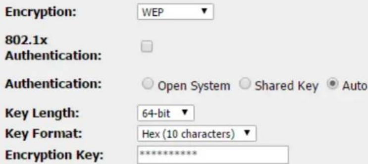
- Click OK button.
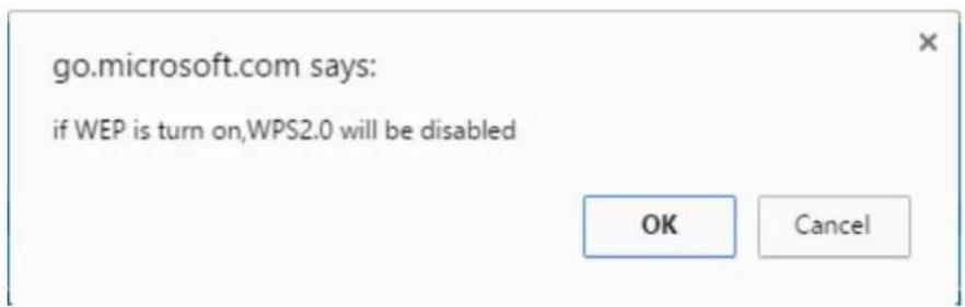
- Change setting successfully! Do not turn off or reboot the Device during this time. Please wait 20 seconds ...
Change setting successfully!
Do not turn off or reboot the Device during this time.
Please wait 19 seconds ...
WEP + Use 802.1x Authentication
WEP aims to provide security by encrypting data over radio waves so that it is protected as it is transmitted from one end point to another. However, it has been found that WEP is not as secure as once believed.
- From the Encryption drop-down list, select WEP setting.
- Check the option of Use 802.1x Authentication.
- Click on the ratio of WEP 64bits or WEP 128bits.
- Enter the Port, IP Address and Password of RADIUS Server:

- Click Save & Apply button.
Wireless Security Setup -wlan2 Wireless Security Setup -2.4G
This page allows you setup the wireless security. Turn on WEP or WPA by using Encryption Keys could prevent any unauthorized access to your wireless network.
Select SSID: LevelOne 2.4G Save Save & Apply Reset


- Change setting successfully! Do not turn off or reboot the Device during this time. Please wait 20 seconds ...
Change setting successfully! Do not turn off or reboot the Device during this time. Please wait 19 seconds ...
WPA2/WPA Mixed + Personal (Pre-Shared Key)
Wi-Fi Protected Access (WPA and WPA2) is a class of systems to secure wireless (Wi-Fi)
computer networks. WPA is designed to work with all wireless network interface cards, but not necessarily with first generation wireless access points. WPA2 implements the full standard, but will not work with some older network cards. Both provide good security, with two significant issues:
- Either WPA or WPA2 must be enabled and chosen in preference to WEP. WEP is usually presented as the first security choice in most installation instructions.
-
In the "Personal" mode, the most likely choice for homes and small offices, a pass phrase is required that, for full security, must be longer than the typical 6 to 8 character passwords users are taught to employ.
-
From the Encryption drop-down list, select WPA2 or WPA Mixed setting.

- Click on the ratio of Personal (Pre-Shared Key).
Authentication Mode: ○ Enterprise (RADIUS) ● Personal (Pre-Shared Key)
- Check the option of AES in WPA2 Cipher Suite if your Encryption is WPA2:
WPA2 Cipher Suite: □ TKIP √ AES
- Check the option of TKIP and/or AES in WPA/WPA2 Cipher Suite if your Encryption is WPA Mixed:
WPA Cipher Suite: ☑ TKIP ☑ AES WPA2 Cipher Suite: ☑ TKIP ☑ AES
- From the Pre-Shared Key Format drop-down list, select Passphrase or Hex (64 characters) setting.
Pre- Shared Key Format: Passphrase Pre- Shared Key Format: HEX (64 characters)
- Enter the Pre-Shared Key depending on selected Passphrase or Hex (64 characters).
Pre-Shared Key:
- Click on Save & Apply button to confirm and return.
Save & Apply
- Change setting successfully! Do not turn off or reboot the Device during this time. Please wait 20 seconds ...
Change setting successfully!
Do not turn off or reboot the Device during this time.
Please wait 19 seconds ...
WPA2/WPA Mixed + Enterprise (RADIUS)
Wi-Fi Protected Access (WPA and WPA2) is a class of systems to secure wireless (Wi-Fi) computer networks. WPA is designed to work with all wireless network interface cards, but not necessarily with first generation wireless access points. WPA2 implements the full standard, but will not work with some older network cards. Both provide good security, with two significant issues:
- Either WPA or WPA2 must be enabled and chosen in preference to WEP. WEP is usually presented as the first security choice in most installation instructions.
-
In the "Personal" mode, the most likely choice for homes and small offices, a pass phrase is required that, for full security, must be longer than the typical 6 to 8 character passwords users are taught to employ.
-
From the Encryption drop-down list, select WPA2 or WPA Mixed setting.
| Encryption: | WPA2 |
| Encryption: | WPA-Mixed |
- Click on the ratio of Enterprise (RADIUS).
Authentication Mode:
- Enterprise (RADIUS) ○ Personal (Pre-Shared Key)
- Check the option of AES in WPA2 Cipher Suite if your Encryption is WPA2:
WPA2 Cipher Suite: □ TKIP √ AES
- Check the option of TKIP and/or AES in WPA/WPA2 Cipher Suite if your Encryption is WPA Mixed:
WPA Cipher Suite: ✓ TKIP ✓ AES WPA2 Cipher Suite: ✓ TKIP ✓ AES
- Enter the Port, IP Address and Password of RADIUS Server:

- Change setting successfully! Do not turn off or reboot the Device during this time. Please wait 20 seconds ...
Change setting successfully!
Do not turn off or reboot the Device during this time.
Please wait 19 seconds ...
Wireless Access Control Mode
For security reason, using MAC ACL's (MAC Address Access List) creates another level of difficulty to hacking a network. A MAC ACL is created and distributed to AP so that only authorized NIC's can connect to the network. While MAC address spoofing is a proven means to hacking a network this can be used in conjunction with additional security measures to increase the level of complexity of the network security decreasing the chance of a breach.
MAC addresses can be add/delete/edit from the ACL list depending on the MAC Access Policy.
If you choose 'Allowed Listed', only those clients whose wireless MAC addresses are in the access control list will be able to connect to your Access Point. When 'Deny Listed' is selected, these wireless clients on the list will not be able to connect the Access Point. To access the Wireless Network Access Control page:
From the left-hand Wireless menu, click on WLAN2 -> Access Control. The following page is displayed:
Wireless Access Control -2.4G
If you choose 'Allowed Listed', only those clients whose wireless MAC addresses are in the access control list will be able to connect to your Access Point. When 'Deny Listed' is selected, these wireless clients on the list will not be able to connect the Access Point.
Wireless Access Control Mode:
Disable
MAC Address:
Comment:
Save
Save & Apply
Reset
Current Access Control List:
MAC Address
Comment
Select
Delete Selected
Delete All
Reset
Allow Listed
If you choose 'Allowed Listed', only those clients whose wireless MAC addresses are in the access control list will be able to connect to your Access Point.
- From the Wireless Access Control Mode drop-down list, select Allowed Listed setting.
- Enter the MAC Address.
- Enter the Comment.
- Click Save & Apply button.
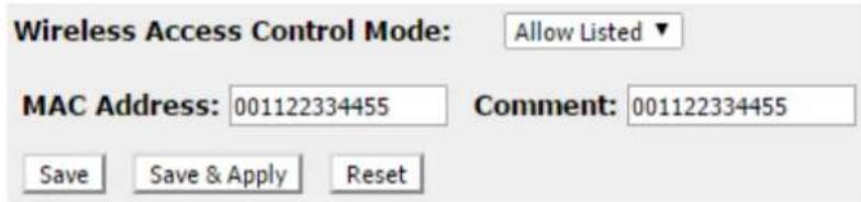
- Click OK button.
Message from webpage


if ACL allow list turn on; WPS2.0 will be disabled

- Change setting successfully! Do not turn off or reboot the Device during this time. Please wait 20 seconds ...
Change setting successfully!
Do not turn off or reboot the Device during this time.
Please wait 19 seconds ...
- The MAC Address that you created has been added in the Current Access Control List.
Current Access Control List:
| MAC Address | Comment | Select | ||
| 00:11:22:33:44:55 | 001122334455 | |||
| Delete Selected | Delete All | Reset | ||
Deny Listed
When 'Deny Listed' is selected, these wireless clients on the list will not be able to connect the Access Point.
- From the Wireless Access Control Mode drop-down list, select Deny Listed setting.
- Enter the MAC Address.
- Enter the Comment.
- Click Save & Apply button.

- Change setting successfully! Do not turn off or reboot the Device during this time. Please wait 20 seconds ...
Change setting successfully! Do not turn off or reboot the Device during this time. Please wait 19 seconds ...
WPS
This page allows you to change the setting for WPS (Wi-Fi Protected Setup). Using this feature could let your wireless client automatically synchronize its setting and connect to the Access Point in a minute without any hassle. To access the Wireless Network WPS page:
From the left-hand Wireless menu, click on WLAN2 -> WPS. The following page is displayed:
Wi-Fi Protected Setup
This page allows you to change the setting for WPS (Wi-Fi Protected Setup). Using this feature could let your wireless client automatically synchronize its setting and connect to the Access Point in a minute without any hassle.

Disable WPS
Apply Changes
Reset
WPS Status:

Configured

UnConfigured
Reset to UnConfigured
Unlock
Auto-lock-down state: unlocked
Self-PIN Number:
14169564
Push Button Configuration:
Start PBC
STOP WSC
Stop WSC
Client PIN Number:
Start PIN
Current Key Info:
| Authentication | Encryption | Key |
| WPA2-Mixed PSK | TKIP+AES | 12345678 |
-Virtual Client-
Self-PIN Number: 14169564
PIN Configuration: Start PIN
Push Button Configuration: Start PBC
Client PIN Number: Start PIN
| Field | Description |
| Disable WPS | Checking this box and clicking “Save & Apply” will disable Wi-Fi Protected Setup. WPS is turned on by default. |
| Self-PIN Number | “Self-PIN Number” is AP’s PIN. Whenever users want to change AP’s PIN, they could click “Regenerate PIN” and then click “Save & Apply”. Moreover, if users want to make their own PIN, they could enter four digit PIN without checksum and then click “Save & Apply”. However, this would not be recommended since the registrar side needs to be supported with four digit PIN. |
| Field | Description |
| Push Button Configuration | Clicking this button will invoke the PBC method of WPS. It is only used when AP acts as a registrar. |
| Save & Apply | Whenever users want to enable/disable WPS or change AP's PIN, they need to apply this button to commit changes. |
| Reset | It restores the original values of “Self-PIN Number” and “Client PIN Number”. |
| Client PIN Number | It is only used when users want their station to join AP's network. The length of PIN is limited to four or eight numeric digits. If users enter eight digit PIN with checksum error, there will be a warning message popping up.If users insist on this PIN, AP will take it. |
12 Status
This page displays the current information for the device. It will display the LAN, WAN, and system firmware information.
- From the Management -> Status menu. The following page is displayed:
Access Point Status
This page shows the current status and some basic settings of the device.
APInfrastructure ClientAPInfrastructure Client
| System | |
| Uptime | 0day:0h:44m:27s |
| Firmware Version | v3411_STD_102_160729 |
| Build Time | Fri Jul 29 13:20:57 CST 2016 |
| Wireless 5G Configuration | |
| Band | 5 GHz (A+N+AC) |
| SSID | LevelOne 5G |
| Channel Number | 36 |
| Encryption | Disabled |
| Wireless 5G Repeater Interface Configuration | |
| SSID | RTK 11n AP RPT0 |
| Encryption | Disabled |
| BSSID | 00:00:00:00:00:00 |
| State | Scanning |
| Wireless 2.4G Configuration | |
| Band | 2.4 GHz (B+G+N) |
| SSID | LevelOne 2.4G |
| Channel Number | 11 |
| Encryption | WPA2 Mixed |
| Wireless 2.4G Repeater Interface Configuration | |
| SSID | RTK 11n AP RPT1 |
| Encryption | Disabled |
| BSSID | 00:00:00:00:00:00 |
| State | Scanning |
| TCP/IP Configuration | |
| Attain IP Protocol | Fixed IP |
| IP Address | 10.0.0.2 |
| Subnet Mask | 255.255.255.0 |
| DHCP Server | Enabled |
| MAC Address | 94:46:96:a0:12:70 |
13 Statistics
This page shows the packet statistics for transmission and reception regarding to network interface.
- From the Management -> Statistics menu. The following page is displayed:
Statistics
This page shows the packet counters for transmission and reception regarding to wireless and Ethernet networks.
| Wireless 1 LAN | Sent Packets | 36 |
| Received Packets | 110 | |
| Wireless 1 Repeater LAN | Sent Packets | 256 |
| Received Packets | 0 | |
| Wireless 2 LAN | Sent Packets | 209 |
| Received Packets | 12980 | |
| Wireless 2 Repeater LAN | Sent Packets | 780 |
| Received Packets | 0 | |
| Ethernet LAN | Sent Packets | 2964 |
| Received Packets | 2437 |
Refresh
14 Firmware Upgrade
About firmware versions
Firmware is a software program. It is stored as read-only memory on your device.
Your device can check whether there are later firmware versions available. If there is a later version, you can download it via the Internet and install it on your device.

If there is a firmware update available you are strongly advised to install it on your device to ensure that you take full advantage of any new feature developments.
Manually updating firmware
You can manually download the latest firmware version from provider's website to your PC's file directory.
Once you have downloaded the latest firmware version to your PC, you can manually select and install it as follows:
- From the MANAGEMENT -> Firmware Upgrade menu. The following page is displayed:
- Click on the Browse... button.
- Once you have selected the file to be installed, click Open. The file's directory path is displayed in the New Firmware Image: text box.
- Click Upload.
Upgrade Firmware
This page allows you upgrade the Access Point firmware to new version. Please note, do not power off the device during the upload because it may crash the system.
Firmware Version:
Select File:
v3.4.11a
Choose File No file chosen
Upload
Reset
Figure 6: Manual Update Installation section
(Note that if you are using certain browsers (such as Opera 7) the Browse button is labeled Choose.)
Use the Choose file box to navigate to the relevant directory where the firmware version is saved.
- Change setting successfully! Do not turn off or reboot the Device during this time. Please wait 105 seconds ...
Change setting successfully!
Do not turn off or reboot the Device during this time.
Please wait 106 seconds ...
15 Backup/Restore Settings
This page allows you save current settings to a file or reload the settings from the file which was saved previously.
Besides, you could reset the current configuration to factory default.
If you do make changes to the default configuration but then wish to revert back to the original factory configuration, you can do so by resetting the device to factory defaults.
Save Settings to File
It allows you save current settings to a file.
- From the MANAGEMENT -> Save/Reload Settings menu. The following page is displayed:
Save/Reload Settings
This page allows you save current settings to a file or reload the settings from the file which was saved previously. Besides, you could reset the current configuration to factory default.

Figure 7: Reset to Defaults page
| Option | Description |
| Save Settings to File | Save the Settings to a File |
| Load Settings from File | Load Settings from a File |
- Click on Save....
Save Settings to File: Save...
- If you are happy with this, click Save and then browse to where the file to be saved. Or click Cancel to cancel it.

Load Settings from File
It allows you to reload the settings from the file which was saved previously.
- From the MANAGEMENT -> Backup/Restore menu. The following page is displayed:
Save/Reload Settings
This page allows you save current settings to a file or reload the settings from the file which was saved previously. Besides, you could reset the current configuration to factory default.

- Click on Choose File to browse to where the config.img is.
Load Settings from File: Choose File No file chosen Upload
- If you are happy with this, click Upload to start to load settings from file.
Load Settings from File: Choose File config.dat Upload
- Change setting successfully! Do not turn off or reboot the Device during this time. Please wait 45 seconds ...
Change setting successfully! Do not turn off or reboot the Device during this time. Please wait 44 seconds ...
Resetting to Defaults
If you do make changes to the default configuration but then wish to revert back to the original factory configuration, you can do so by resetting the device to factory defaults.

If you reset your device to factory defaults, all previous configuration changes that you have made are overwritten by the factory default configuration.
Software Reset:
- From the left-hand Management menu, click on Reset factory default. The following page is displayed:
Save/Reload Settings
This page allows you save current settings to a file or reload the settings from the file which was saved previously. Besides, you could reset the current configuration to factory default.

Figure 8: Reset to Defaults page
2. Click on Reset
Reset Settings to Default:
Reset
- This page reminds you that resetting to factory defaults cannot be undone – any changes that you have made to the basic settings will be replaced. If you are happy with this, click OK. Or click Cancel to cancel it.
Message from webpage


Do you really want to reset the current settings to default?
OK
Cancel
- Reload setting successfully! The Router is booting. Do not turn off or reboot the Device during this time. Please wait 60 seconds ...
Reload setting successfully!
The Router is booting.
Do not turn off or reboot the Device during this time.
Please wait 59 seconds ...
16 Password
This page is used to set the account to access the web server of Access Point. Empty user name and password will disable the protection.
To change the default password:
- From the left Management menu, click on Password. The following page is displayed:

Figure 9: Currently Defined Administration Password: Setup page
A
Configuring your Computers
This appendix provides instructions for configuring the Internet settings on your computers to work with the Portable Repeater.
Configuring Ethernet PCs
Before you begin
By default, the Portable Repeater automatically assigns the required Internet settings to your PCs. You need to configure the PCs to accept this information when it is assigned.

In some cases, you may want to assign Internet information manually to some or all of your computers rather than allow the Portable Repeater to do so. See Assigning static Internet information to your PCs for instructions.
- If you have connected your LAN PCs via Ethernet to the Portable Repeater, follow the instructions that correspond to the operating system installed on your PC:
- Windows® XP PCs
- Windows 2000 PCs
- Windows Me PCs
- Windows 95, 98 PCs
• Windows NT 4.0 workstations
Windows® XP PCs
- In the Windows task bar, click the Start button, and then click Control Panel.
- Double-click the Network Connections icon.
- In the LAN or High-Speed Internet window, right-click on the icon corresponding to your network interface card (NIC) and select Properties. (Often, this icon is labeled Local Area Connection).
The Local Area Connection dialog box is displayed with a list of currently installed network items. - Ensure that the check box to the left of the item labeled Internet Protocol TCP/IP is checked and click Properties.
- In the Internet Protocol (TCP/IP) Properties dialog box, click the radio button labeled Obtain an IP address automatically. Also click the radio button labeled Obtain DNS server address automatically.
- Click OK twice to confirm your changes, and then close the Control Panel.
Windows 2000 PCs
First, check for the IP protocol and, if necessary, install it:
- In the Windows task bar, click the Start button, point to Settings, and then click Control Panel.
-
Double-click the Network and Dial-up Connections icon.
-
In the Network and Dial-up Connections window, right-click the Local Area Connection icon, and then select Properties. The Local Area Connection Properties dialog box is displayed with a list of currently installed network components. If the list includes Internet Protocol (TCP/IP), then the protocol has already been enabled. Skip to step 10.
- If Internet Protocol (TCP/IP) does not display as an installed component, click Install...
- In the Select Network Component Type dialog box, select Protocol, and then click Add...
- Select Internet Protocol (TCP/IP) in the Network Protocols list, and then click OK. You may be prompted to install files from your Windows 2000 installation CD or other media. Follow the instructions to install the files.
- If prompted, click OK to restart your computer with the new settings.
Next, configure the PCs to accept IP information assigned by the Portable Repeater:
- In the Control Panel, double-click the Network and Dial-up Connections icon.
- In the Network and Dial-up Connections window, right-click the Local Area Connection icon, and then select Properties.
- In the Local Area Connection Properties dialog box, select Internet Protocol (TCP/IP), and then click Properties.
- In the Internet Protocol (TCP/IP) Properties dialog box, click the radio button labeled Obtain an IP address automatically. Also click the radio button labeled Obtain DNS server address automatically.
- Click OK twice to confirm and save your changes, and then close the Control Panel.
Windows Me PCs
-
In the Windows task bar, click the Start button, point to Settings, and then click Control Panel.
-
Double-click the Network and Dial-up Connections icon.
-
In the Network and Dial-up Connections window, right-click the Network icon, and then select Properties.
The Network Properties dialog box displays with a list of currently installed network components. If the list includes Internet Protocol (TCP/IP), then the protocol has already been enabled. Skip to step 11.
-
If Internet Protocol (TCP/IP) does not display as an installed component, click Add...
-
In the Select Network Component Type dialog box, select Protocol, and then click Add...
-
Select Microsoft in the Manufacturers box.
-
Select Internet Protocol (TCP/IP) in the Network Protocols list, and then click OK.
You may be prompted to install files from your Windows Me installation CD or other media. Follow the instructions to install the files.
- If prompted, click OK to restart your computer with the new settings.
Next, configure the PCs to accept IP information assigned by the Portable Repeater:
-
In the Control Panel, double-click the Network and Dial-up Connections icon.
-
In Network and Dial-up Connections window, right-click the Network icon, and then select Properties.
-
In the Network Properties dialog box, select TCP/IP, and then click Properties.
-
In the TCP/IP Settings dialog box, click the radio button labeled Server assigned IP address. Also click the radio button labeled Server assigned name server address.
-
Click OK twice to confirm and save your changes, and then close the Control Panel.
Windows 95, 98 PCs
First, check for the IP protocol and, if necessary, install it:
-
In the Windows task bar, click the Start button, point to Settings, and then click Control Panel.
-
Double-click the Network icon.
The Network dialog box displays with a list of currently installed network components. If the list includes TCP/IP, and then the protocol has already been enabled. Skip to step 9.
- If TCP/IP does not display as an installed component, click Add...
The Select Network Component Type dialog box displays.
- Select Protocol, and then click Add...
The Select Network Protocol dialog box displays.
-
Click on Microsoft in the Manufacturers list box, and then click TCP/IP in the Network Protocols list box.
-
Click OK to return to the Network dialog box, and then click OK again.
You may be prompted to install files from your Windows 95/98 installation CD. Follow the instructions to install the files.
- Click OK to restart the PC and complete the TCP/IP installation.
Next, configure the PCs to accept IP information assigned by the Portable Repeater:
-
Open the Control Panel window, and then click the Network icon.
-
Select the network component labeled TCP/IP, and then click Properties.
If you have multiple TCP/IP listings, select the listing associated with your network card or adapter.
-
In the TCP/IP Properties dialog box, click the IP Address tab.
-
Click the radio button labeled Obtain an IP address automatically.
-
Click the DNS Configuration tab, and then click the radio button labeled Obtain an IP address automatically.
-
Click OK twice to confirm and save your changes. You will be prompted to restart Windows.
-
Click Yes.
Windows NT 4.0 workstations
First, check for the IP protocol and, if necessary, install it:
-
In the Windows NT task bar, click the Start button, point to Settings, and then click Control Panel.
-
In the Control Panel window, double click the Network icon.
-
In the Network dialog box, click the Protocols tab.
The Protocols tab displays a list of currently installed network protocols. If the list includes TCP/IP, then the protocol has already been enabled. Skip to step 9.
-
If TCP/IP does not display as an installed component, click Add...
-
In the Select Network Protocol dialog box, select TCP/IP, and then click OK.
You may be prompted to install files from your Windows NT installation CD or other media. Follow the instructions to install the files.
After all files are installed, a window displays to inform you that a TCP/IP service called DHCP can be set up to dynamically assign IP information.
- Click Yes to continue, and then click OK if prompted to restart your computer.
Next, configure the PCs to accept IP information assigned by the Portable Repeater:
- Open the Control Panel window, and then double-click the Network icon.
- In the Network dialog box, click the Protocols tab.
- In the Protocols tab, select TCP/IP, and then click Properties.
- In the Microsoft TCP/IP Properties dialog box, click the radio button labeled Obtain an IP address from a DHCP server.
- Click OK twice to confirm and save your changes, and then close the Control Panel.
Assigning static Internet information to your PCs
If you are a typical user, you will not need to assign static Internet information to your LAN PCs because your ISP automatically assigns this information for you.
In some cases however, you may want to assign Internet information to some or all of your PCs directly (often called "statically"), rather than allowing the Portable Repeater to assign it. This option may be desirable (but not required) if:
- You have obtained one or more public IP addresses that you want to always associate with specific computers (for example, if you are using a computer as a public web server).
- You maintain different subnets on your LAN (subnets are described in Appendix B).
Before you begin, you must have the following information available:
- The IP address and subnet mask of each PC
- The IP address of the default gateway for your LAN. In most cases, this is the address assigned to the LAN port on the Portable Repeater. By default, the LAN port is assigned the IP address 192.168.1.1. (You can change this number or another number can be assigned by your ISP. See Addressing for more information.)
- The IP address of your ISP's Domain Name System (DNS) server.
On each PC to which you want to assign static information, follow the instructions relating only to checking for and/or installing the IP protocol. Once it is installed, continue to follow the instructions for displaying each of the Internet Protocol (TCP/IP) properties. Instead of enabling dynamic assignment of the IP addresses for the computer, DNS server and default gateway, click the radio buttons that enable you to enter the information manually.

Note
Your PCs must have IP addresses that place them in the same subnet as the Portable Repeater's LAN port. If you manually assign IP information to all your LAN PCs, you can follow the instructions i Addressing to change the LAN port IP address accordingly.
B IP Addresses, Network Masks, and Subnets
IP Addresses

This section refers only to IP addresses for IPv4 (version 4 of the Internet Protocol). IPv6 addresses are not covered.
This section assumes basic knowledge of binary numbers, bits, and bytes.
IP addresses, the Internet's version of telephone numbers, are used to identify individual nodes (computers or devices) on the Internet. Every IP address contains four numbers, each from 0 to 255 and separated by dots (periods), e.g. 20.56.0.211. These numbers are called, from left to right, field1, field2, field3, and field4.
This style of writing IP addresses as decimal numbers separated by dots is called dotted decimal notation. The IP address 20.56.0.211 is read "twenty dot fifty-six dot zero dot two-eleven."
Structure of an IP address
IP addresses have a hierarchical design similar to that of telephone numbers. For example, a 7-digit telephone number starts with a 3-digit prefix that identifies a group of thousands of telephone lines, and ends with four digits that identify one specific line in that group.
Similarly, IP addresses contain two kinds of information:
- Network ID
Identifies a particular network within the Internet or intranet - Host ID
Identifies a particular computer or device on the network
The first part of every IP address contains the network ID, and the rest of the address contains the host ID. The length of the network ID depends on the network's class (see following section). The table below shows the structure of an IP address.
| Class A |
| Class B |
| Class C |
| Field1 | Field2 | Field3 | Field4 |
| Network ID | Host ID | ||
| Network ID | Host ID | ||
| Network ID | Host ID | ||
Here are some examples of valid IP addresses:
Class A: 10.30.6.125 (network = 10, host = 30.6.125)
Class B: 129.88.16.49 (network = 129.88, host = 16.49)
Class C: 192.60.201.11 (network = 192.60.201, host = 11)
Network classes
The three commonly used network classes are A, B, and C. (There is also a class D but it has a special use beyond the
scope of this discussion.) These classes have different uses and characteristics.
Class A networks are the Internet's largest networks, each with room for over 16 million hosts. Up to 126 of these huge networks can exist, for a total of over 2 billion hosts. Because of their huge size, these networks are used for WANs and by organizations at the infrastructure level of the Internet, such as your ISP.
Class B networks are smaller but still quite large, each able to hold over 65,000 hosts. There can be up to 16,384 class B networks in existence. A class B network might be appropriate for a large organization such as a business or government agency.
Class C networks are the smallest, only able to hold 254 hosts at most, but the total possible number of class C networks exceeds 2 million (2,097,152 to be exact). LANs connected to the Internet are usually class C networks.
Some important notes regarding IP addresses:
- The class can be determined easily from field1:
field1 = 1-126: Class A
field1 = 128-191: Class B
field1 = 192-223: Class C
(field1 values not shown are reserved for special uses)
- A host ID can have any value except all fields set to 0 or all fields set to 255, as those values are reserved for special uses.
Subnet masks

A mask looks like a regular IP address, but contains a pattern of bits that tells what parts of an IP address are the network ID and what parts are the host ID: bits set to 1 mean "this bit is part of the network ID" and bits set to 0 mean "this bit is part of the host ID."
Subnet masks are used to define subnets (what you get after dividing a network into smaller pieces). A subnet's network ID is created by "borrowing" one or more bits from the host ID portion of the address. The subnet mask identifies these host ID bits.
For example, consider a class C network 192.168.1. To split this into two subnets, you would use the subnet mask:
255.255.255.128
It's easier to see what's happening if we write this in binary:
-
-
- 10000000
-
As with any class C address, all of the bits in field1 through field3 are part of the network ID, but note how the mask specifies that the first bit in field4 is also included. Since this extra bit has only two values (0 and 1), this means there are two subnets. Each subnet uses the remaining 7 bits in field4 for its host IDs, which range from 1 to 126 hosts (instead of the usual 0 to 255 for a class C address).
Similarly, to split a class C network into four subnets, the mask is:
255.255.255.192 or 1111111.1111111. 11111111.11000000
The two extra bits in field4 can have four values (00, 01, 10, 11), so there are four subnets. Each subnet uses the remaining six bits in field4 for its host IDs, ranging from 1 to 62.

Sometimes a subnet mask does not specify any additional network ID bits, and thus no subnets. Such a mask is called a default subnet mask. These masks are:
Class A: 255.0.0.0
Class B: 255.255.0.0
Class C: 255.255.255.0
These are called default because they are used when a network is initially configured, at which time it has no subnets.
C UPnP Control Point Software on Windows ME/XP
This appendix provides instructions for configuring the UPnP on your computers to work with the Portable Repeater.
UPnP is an architecture for pervasive peer-to-peer network connectivity of intelligent appliances, Wireless devices, and PCs of all form factors. It is designed to bring easy-to-use, flexible, standards-based connectivity to ad-hoc or unmanaged networks whether in the home, in a small business, public spaces, or attached to the Internet. UPnP is a distributed, open networking architecture that leverages TCP/IP and the Web technologies to enable seamless proximity networking in addition to control and data transfer among networked devices in the home, office, and public spaces.
UPnP is more than just a simple extension of the plug and play peripheral model. It is designed to support zero-configuration, "invisible" networking, and automatic discovery for a breadth of device categories from a wide range of vendors. This means a device can dynamically join a network, obtain an IP address, convey its capabilities, and learn about the presence and capabilities of other devices. DHCP and DNS servers are optional and are used only if available on the network. Finally, a device can leave a network smoothly and automatically without leaving any unwanted state behind.
UPnP Control Point Software on Windows ME
To install the control point software on Windows ME:
- In the Control Panel, select "Add/Remove Programs".
- In the "Add/Remove Programs Properties" dialog box, select the "Windows Setup" tab. In the "Components" list, double click on the "Communications" entry.
- In the "Communications" dialog box, scroll down the "Components" list to display the UPnP entry. Select the entry, click "OK".
- Click "OK" to finish the "Add/Remove Programs" dialog.
- Reboot your system.
Once you have installed the UPnP software and you have rebooted (and your network includes the IGD system), you should be able to see the IGD controlled device on your network.
UPnP Control Point Software on Windows XP with Firewall
On Windows XP versions earlier than SP2, Firewall support is provided by the Windows XP Internet Connection Firewall. You cannot use the Windows XP Internet Connection Firewall support on a system that you intend to use as a UPnP control point. If this feature is enabled, although the control point system may display controlled devices in the list of network devices, the control point system cannot participate in UPnP communication. (This restriction also applies to controlled devices running on Windows XP systems earlier than SP2.)
On Windows XP SP2 and later, Firewall support is provided by Windows Firewall. Unlike earlier versions, Windows XP SP2 can be used on a system that you intend to use as a UPnP control point.
To turn off the Firewall capability on any version of Windows XP, follow the steps below:
- In the Control Panel, select "Network and Internet Connections".
- In the "Network and Internet Connections" dialog box, select "Network Connections".
- In the "Network Connections" dialog box, right-click on the local area connection entry for your network; this will display a menu. Select the "Properties" menu entry.
- In the "Local Area Connection Properties" dialog box, select the "Advanced" tab. Disable the Internet Connection Firewall by de-selecting the entry with the following label:
"Protect my computer and network by limiting or preventing access to the computer from the Internet".
- Click "OK".
SSDP requirements
You must have SSDP Discovery Service enabled on your Windows XP system to use the UPnP Control point software.
SSDP Discovery Service is enabled on a default installation of Windows XP. To check if it is enabled on your system, look in Control Panel > Administrative Tools > Services).
Installation procedure
To install the Control point software on Windows XP, follow the steps below:
- In the Control Panel, select "Add/Remove Programs".
- In the "Add or Remove Programs" dialog box, click the "Add / Remove Windows Components" button.
-
In the "Windows Component Wizard" dialog box, scroll down the list to display the "Networking Services" entry. Highlight (select) the entry, and click on the "Details" button.
-
The "Networking Services" window is displayed.
The subcomponents shown in the Networking Services window will be different depending on if you are using Windows XP, Windows XP (SP1), or Windows XP (SP2).
If you are using Windows XP SP2, the Networking Services window will display the following list of sub-components:
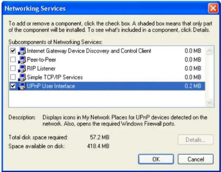
- Select the following entries from the "Networking Services" window and then click "OK":
If you are using Windows XP, select:
- "Universal Plug and Play".
If you are using Windows XP SP1, select:
- "Internet Gateway Device discovery and Control Client".
• "Universal Plug and Play".
If you are using Windows XP SP2, select:
- "Internet Gateway Device discovery and Control Client".
- "UPnP User Interface".
- Reboot your system.
Once you have installed the UPnP software and you have rebooted (and your network includes the IGD system), you should be able to see the IGD controlled device on your network.
For example, from the Network Connections window you should see the Internet Gateway Device:

D Troubleshooting
This appendix suggests solutions for problems you may encounter in installing or using the Portable Repeater, and provides instructions for using several IP utilities to diagnose problems.
Contact Customer Support if these suggestions do not resolve the problem.
Troubleshooting Suggestions
| Problem | Troubleshooting Suggestion |
| LEDs | |
| Power LED does not illuminate after product is turned on. | Verify that you are using the power cable provided with the device and that it is securely connected to the Portable Repeater and a wall socket/power strip. |
| LINK LAN LED does not illuminate after Ethernet cable is attached. | Verify that the Ethernet cable is securely connected to your LAN hub or PC and to the Portable Repeater. Make sure the PC and/or hub is turned on.Verify that your cable is sufficient for your network requirements. A 100 Mbit/sec network (10BaseTx) should use cables labeled CAT 5. A 10Mbit/sec network may tolerate lower quality cables. |
| Internet Access | |
| My PC cannot access the Internet | Use the ping utility (discussed in the following section) to check whether your PC can communicate with the device's LAN IP address (by default 192.168.1.1). If it cannot, check the Ethernet cabling.If you statically assigned a private IP address to the computer, (not a registered public address), verify the following:Check that the gateway IP address on the computer is your public IP address (see Current Status for instructions on viewing the IP information.) If it is not, correct the address or configure the PC to receive IP information automatically.Verify with your ISP that the DNS server specified for the PC is valid.Correct the address or configure the PC to receive this information automatically. |
| My LAN PCs cannot display web pages on the Internet. | Verify that the DNS server IP address specified on the PCs is correct for your ISP, as discussed in the item above. If you specified that the DNS server be assigned dynamically from a server, then verify with your ISP that the address configured on the Portable Repeater is correct, then You can use the ping utility, to test connectivity with your ISP's DNS server. |
| I forgot/lost my user ID or password. | If you have not changed the password from the default, try using “admin” the user ID and “admin” as password. Otherwise, you can reset the device to the default configuration by pressing the Reset Default button on the Rare panel of the device (see Rare Panel). Then, type the default User ID and password shown above.WARNING:Resetting the device removes any custom settings and returns all settings to their default values. |
| I cannot access the web pages from my browser. | Use the ping utility, discussed in the following section, to check whether your PC can communicate with the device’s LAN IP address (by default 192.168.1.1). If it cannot, check the Ethernet cabling.Verify that you are using Internet Explorer or Netscape Navigator v4.0 or later.Verify that the PC’s IP address is defined as being on the same subnet as the IP address assigned to the LAN port on the Portable Repeater. |
| My changes to the web pages are not being retained. | Be sure to use the Confirm Changes/Apply function after any changes. |
Web pages
Diagnosing Problem using IP Utilities
ping
Ping is a command you can use to check whether your PC can recognize other computers on your network and the Internet. A ping command sends a message to the computer you specify. If the computer receives the message, it sends messages in reply. To use it, you must know the IP address of the computer with which you are trying to communicate.
On Windows-based computers, you can execute a ping command from the Start menu. Click the Start button, and then click Run. In the Open text box, type a statement such as the following:
ping 192.168.1.1
Click OK. You can substitute any private IP address on your LAN or a public IP address for an Internet site, if known.
If the target computer receives the message, a Command Prompt window is displayed:
![Microsoft Windows [Version 10.0.10240] (c) 2015 Microsoft Corporation. All rights reserved. C:\Users\970A>ping 192.168.1.1 Pinging 192.168.1.1 with 32 bytes of data: Reply from 192.168.1.1: bytes=32 time<1ms TTL=64 Reply from 192.168.1.1: bytes=32 time<1ms TTL=64 Reply from 192.168.1.1: bytes=32 tim…](/content/2026/07/1416435/images/2b151831f6d78296c82475bb40ac02a56ef337ec680e679292a04da142364212.jpg)
Figure 10: Using the ping Utility
If the target computer cannot be located, you will receive the message Request timed out.
Using the ping command, you can test whether the path to the Portable Repeater is working (using the preconfigured default LAN IP address 192.168.1.1) or another address you assigned.
You can also test whether access to the Internet is working by typing an external address, such as that for www.yahoo.com (216.115.108.243). If you do not know the IP address of a particular Internet location, you can use the nslookup command, as explained in the following section.
From most other IP-enabled operating systems, you can execute the same command at a command prompt or through a system administration utility.
nslookup
You can use the nslookup command to determine the IP address associated with an Internet site name. You specify the common name, and the nslookup command looks up the name in on your DNS server (usually located with your ISP). If that name is not an entry in your ISP's DNS table, the request is then referred to another higher-level server, and so on, until the entry is found. The server then returns the associated IP address.
On Windows-based computers, you can execute the nslookup command from the Start menu. Click the Start button, and then click Run. In the Open text box, type the following:
Nslookup
Click OK. A Command Prompt window displays with a bracket prompt (>). At the prompt, type the name of the Internet address that you are interested in, such as www.microsoft.com.
The window will display the associate IP address, if known, as shown below:

Figure 11: Using the nslookup Utility
There may be several addresses associated with an Internet name. This is common for web sites that receive heavy traffic; they use multiple, redundant servers to carry the same information.
To exit from the nslookup utility, type exit and press [Enter] at the command prompt.
E LICENSE STATEMENT / GPL CODE STATEMENT
This product resp. the here
(http://global.level1.com/downloads.php?action=init) for downloading offered software includes software code developed by third parties, including software code subject to the GNU General Public License Version 2 ("GPLv2") and GNU Lesser General Public License 2.1 („LGPLv2.1“).
WRITTEN OFFER FOR GPL/LGPL SOURCE CODE
We will provide everyone upon request the applicable GPLv2 and LGPLv2.1 source code files via CDROM or similar storage medium for a nominal cost to cover shipping and media charges as allowed under the GPLv2 and LGPLv2.1. This offer is valid for 3 years. GPLv2 and LGPLv2 inquiries: Please direct all GPL and LGPL inquiries to the following address:
Digital Data Communications GmbH
Zeche-Norm-Str. 25
44319 Dortmund
Deutschland
Phone: +49 231 9075 - 0
Fax: +49 231 9075 - 184
Email: support@level1.com
Web: www.level1.com
NO WARRANTY
This program is distributed in the hope that it will be useful, but WITHOUT ANY WARRANTY; without even the implied warranty of MERCHANTABILITY or FITNESS FOR A
PARTICULAR PURPOSE. See the GNU General Public
License for more details. IN NO EVENT UNLESS
REQUIRED BY APPLICABLE LAW OR AGREED TO IN
WRITING WILL ANY COPYRIGHT HOLDER, OR ANY OTHER PARTY WHO MAY MODIFY AND/OR REDISTRIBUTE THE PROGRAM AS PERMITTED ABOVE, BE LIABLE TO YOU FOR DAMAGES, INCLUDING ANY GENERAL, SPECIAL, INCIDENTAL OR CONSEQUENTIAL DAMAGES ARISING OUT OF THE USE OR INABILITY TO USE THE PROGRAM (INCLUDING BUT NOT LIMITED TO LOSS OF DATA OR DATA BEING RENDERED INACCURATE OR LOSSES SUSTAINED BY YOU OR THIRD PARTIES OR A FAILURE OF THE PROGRAM TO OPERATE WITH ANY OTHER PROGRAMS), EVEN IF SUCH HOLDER OR OTHER PARTY HAS BEEN ADVISED OF THE POSSIBILITY OF SUCH DAMAGES.
GNU GENERAL PUBLIC LICENSE
Version 2, June 1991
Copyright (C) 1989, 1991 Free Software Foundation, Inc.
51 Franklin Street, Fifth Floor, Boston, MA 02110-1301, USA
Everyone is permitted to copy and distribute verbatim copies of this license document, but changing it is not allowed.
Preamble
The licenses for most software are designed to take away your freedom to share and change it. By contrast, the GNU General Public License is intended to guarantee your freedom to share and change free software--to make sure the software is free for all its users. This General Public License applies to most of the Free Software Foundation's software and to any other program whose authors commit to using it. (Some other Free Software Foundation software is covered by the GNU Lesser General Public License instead.) You can apply it to your programs, too.
When we speak of free software, we are referring to freedom, not price. Our General Public Licenses are designed to make sure that you have the freedom to distribute copies of free software (and charge for this
service if you wish), that you receive source code or can get it if you want it, that you can change the software or use pieces of it in new free programs; and that you know you can do these things.
To protect your rights, we need to make restrictions that forbid anyone to deny you these rights or to ask you to surrender the rights. These restrictions translate to certain responsibilities for you if you distribute copies of the software, or if you modify it.
For example, if you distribute copies of such a program, whether gratis or for a fee, you must give the recipients all the rights that you have. You must make sure that they, too, receive or can get the source code. And you must show them these terms so they know their rights.
We protect your rights with two steps: (1) copyright the software, and (2) offer you this license which gives you legal permission to copy, distribute and/or modify the software.
Also, for each author's protection and ours, we want to make certain that everyone understands that there is no warranty for this free software. If the software is modified by someone else and passed on, we want its recipients to know that what they have is not the original, so that any problems introduced by others will not reflect on the original authors' reputations.
Finally, any free program is threatened constantly by software patents. We wish to avoid the danger that redistributors of a free program will individually obtain patent licenses, in effect making the program proprietary. To prevent this, we have made it clear that any patent must be licensed for everyone's free use or not licensed at all.
The precise terms and conditions for copying, distribution and modification follow.
TERMS AND CONDITIONS FOR COPYING, DISTRIBUTION AND MODIFICATION
- This License applies to any program or other work which contains a notice placed by the copyright holder saying it may be distributed under the terms of this General Public License. The "Program", below, refers to any such program or work, and a "work based on the Program" means either the Program or any derivative work under copyright law: that is to say, a work containing the Program or a portion of it, either verbatim or with modifications and/or translated into another language.
(Hereinafter, translation is included without limitation in the term "modification".) Each licensee is addressed as "you". Activities other than copying, distribution and modification are not covered by this License; they are outside its scope. The act of running the Program is not restricted, and the output from the Program is covered only if its contents constitute a work based on the Program (independent of having been made by running the Program). Whether that is true depends on what the Program does.
- You may copy and distribute verbatim copies of the Program's source code as you receive it, in any medium, provided that you conspicuously and appropriately publish on each copy an appropriate copyright notice and disclaimer of warranty; keep intact all the notices that refer to this License and to the absence of any warranty; and give any other recipients of the Program a copy of this License along with the Program.
You may charge a fee for the physical act of transferring a copy, and you may at your option offer warranty protection in exchange for a fee.
- You may modify your copy or copies of the Program or any portion of it, thus forming a work based on the Program, and copy and distribute such modifications or work under the terms of Section 1 above, provided that you also meet all of these conditions:
a) You must cause the modified files to carry prominent notices stating that you changed the files and the date of any change.
b) You must cause any work that you distribute or publish, that in whole or in part contains or is derived from the Program or any part thereof, to be licensed as a whole at no charge to all third parties under the terms of this License.
c) If the modified program normally reads commands interactively when run, you must cause it, when started running for such interactive use in the most ordinary way, to print or display an announcement including an appropriate copyright notice and a notice that there is no warranty (or else, saying that you provide a warranty) and that users may redistribute the program under these conditions, and telling the user how to view a copy of this License. (Exception: if the Program itself is interactive but
does not normally print such an announcement, your work based on the Program is not required to print an announcement.)
These requirements apply to the modified work as a whole. If identifiable sections of that work are not derived from the Program, and can be reasonably considered independent and separate works in themselves, then this License, and its terms, do not apply to those sections when you distribute them as separate works. But when you distribute the same sections as part of a whole which is a work based on the Program, the distribution of the whole must be on the terms of this License, whose permissions for other licensees extend to the entire whole, and thus to each and every part regardless of who wrote it.
Thus, it is not the intent of this section to claim rights or contest your rights to work written entirely by you; rather, the intent is to exercise the right to control the distribution of derivative or collective works based on the Program.
In addition, mere aggregation of another work not based on the Program with the Program (or with a work based on the Program) on a volume of a storage or distribution medium does not bring the other work under the scope of this License.
- You may copy and distribute the Program (or a work based on it, under Section 2) in object code or executable form under the terms of Sections 1 and 2 above provided that you also do one of the following:
we use this doubled UL to get the sub-sections indented, while making the bullets as unobvious as possible.
a) Accompany it with the complete corresponding machine-readable source code, which must be distributed under the terms of Sections 1 and 2 above on a medium customarily used for software interchange; or,
b) Accompany it with a written offer, valid for at least three years, to give any third party, for a charge no more than
your cost of physically performing source distribution, a complete machine-readable copy of the corresponding source code, to be distributed under the terms of Sections 1 and 2 above on a medium customarily used for software interchange; or,
c) Accompany it with the information you received as to the offer to distribute corresponding source code. (This alternative is allowed only for noncommercial distribution and only if you received the program in object code or executable form with such an offer, in accord with Subsection b above.)
The source code for a work means the preferred form of the work for making modifications to it. For an executable work, complete source code means all the source code for all modules it contains, plus any associated interface definition files, plus the scripts used to control compilation and installation of the executable. However, as a special exception, the source code distributed need not include
anything that is normally distributed (in either source or binary form) with the major components (compiler, kernel, and so on) of the operating system on which the executable runs, unless that component itself accompanies the executable.
If distribution of executable or object code is made by offering access to copy from a designated place, then offering equivalent access to copy the source code from the same place counts as distribution of the source code, even though third parties are not compelled to copy the source along with the object code.
-
You may not copy, modify, sublicense, or distribute the Program except as expressly provided under this License. Any attempt otherwise to copy, modify, sublicense or distribute the Program is void, and will automatically terminate your rights under this License. However, parties who have received copies, or rights, from you under this License will not have their licenses terminated so long as such parties remain in full compliance.
-
You are not required to accept this License, since you have not signed it. However, nothing else grants you permission to modify or distribute the Program or its derivative works. These actions are prohibited by law if you do not accept this License. Therefore, by modifying or distributing the Program (or any work based on the Program), you indicate your acceptance of this License to do so, and all its terms and conditions for copying, distributing or modifying the Program or works based on it.
-
Each time you redistribute the Program (or any work based on the Program), the recipient automatically receives a license from the original licensor to copy, distribute or modify the Program subject to these terms and conditions. You may not impose any further restrictions on the recipients' exercise of the rights granted herein. You are not responsible for enforcing compliance by third parties to this License.
-
If, as a consequence of a court judgment or allegation of patent infringement or for any other reason (not limited
to patent issues), conditions are imposed on you (whether by court order, agreement or otherwise) that contradict the conditions of this License, they do not excuse you from the conditions of this License. If you cannot distribute so as to satisfy simultaneously your obligations under this License and any other pertinent obligations, then as a consequence you may not distribute the Program at all.
For example, if a patent license would not permit royalty-free redistribution of the Program by all those who receive copies directly or indirectly through you, then the only way you could satisfy both it and this License would be to refrain entirely from distribution of the Program.
If any portion of this section is held invalid or unenforceable under any particular circumstance, the balance of the section is intended to apply and the section as a whole is intended to apply in other circumstances.
It is not the purpose of this section to induce you to infringe any patents or other property right claims or to contest validity of any such claims; this section has the
sole purpose of protecting the integrity of the free software distribution system, which is implemented by public license practices. Many people have made generous contributions to the wide range of software distributed through that system in reliance on consistent application of that system; it is up to the author/donor to decide if he or she is willing to distribute software through any other system and a licensee cannot impose that choice.
This section is intended to make thoroughly clear what is believed to be a consequence of the rest of this License.
-
If the distribution and/or use of the Program is restricted in certain countries either by patents or by copyrighted interfaces, the original copyright holder who places the Program under this License may add an explicit geographical distribution limitation excluding those countries, so that distribution is permitted only in or among countries not thus excluded. In such case, this License incorporates the limitation as if written in the body of this License.
-
The Free Software Foundation may publish revised and/or new versions of the General Public License from time to time. Such new versions will be similar in spirit to the present version, but may differ in detail to address new problems or concerns.
Each version is given a distinguishing version number. If the Program specifies a version number of this License which applies to it and "any later version", you have the option of following the terms and conditions either of that version or of any later version published by the Free Software Foundation. If the Program does not specify a version number of this License, you may choose any version ever published by the Free Software Foundation.
- If you wish to incorporate parts of the Program into other free programs whose distribution conditions are different, write to the author to ask for permission. For software which is copyrighted by the Free Software Foundation, write to the Free Software Foundation; we sometimes make exceptions for this. Our decision will be
guided by the two goals of preserving the free status of all derivatives of our free software and of promoting the sharing and reuse of software generally.
NO WARRANTY
-
BECAUSE THE PROGRAM IS LICENSED FREE OF CHARGE, THERE IS NO WARRANTY FOR THE PROGRAM, TO THE EXTENT PERMITTED BY APPLICABLE LAW. EXCEPT WHEN OTHERWISE STATED IN WRITING THE COPYRIGHT HOLDERS AND/OR OTHER PARTIES PROVIDE THE PROGRAM "AS IS" WITHOUT WARRANTY OF ANY KIND, EITHER EXPRESSED OR IMPLIED, INCLUDING, BUT NOT LIMITED TO, THE IMPLIED WARRANTIES OF MERCHANTABILITY AND FITNESS FOR A PARTICULAR PURPOSE. THE ENTIRE RISK AS TO THE QUALITY AND PERFORMANCE OF THE PROGRAM IS WITH YOU. SHOULD THE PROGRAM PROVE DEFECTIVE, YOU ASSUME THE COST OF ALL NECESSARY SERVICING, REPAIR OR CORRECTION.
-
IN NO EVENT UNLESS REQUIRED BY APPLICABLE
LAW OR AGREED TO IN WRITING WILL ANY
COPYRIGHT HOLDER, OR ANY OTHER PARTY WHO
MAY MODIFY AND/OR REDISTRIBUTE THE PROGRAM
AS PERMITTED ABOVE, BE LIABLE TO YOU FOR
DAMAGES, INCLUDING ANY GENERAL, SPECIAL,
INCIDENTAL OR CONSEQUENTIAL DAMAGES
ARISING OUT OF THE USE OR INABILITY TO USE THE
PROGRAM (INCLUDING BUT NOT LIMITED TO LOSS
OF DATA OR DATA BEING RENDERED INACCURATE
OR LOSSES SUSTAINED BY YOU OR THIRD PARTIES
OR A FAILURE OF THE PROGRAM TO OPERATE WITH
ANY OTHER PROGRAMS), EVEN IF SUCH HOLDER
OR OTHER PARTY HAS BEEN ADVISED OF THE
POSSIBILITY OF SUCH DAMAGES.
END OF TERMS AND
CONDITIONS
How to Apply These Terms to
Your New Programs
If you develop a new program, and you want it to be of the greatest possible use to the public, the best way to achieve this is to make it free software which everyone can redistribute and change under these terms.
To do so, attach the following notices to the program. It is safest to attach them to the start of each source file to most effectively convey the exclusion of warranty; and each file should have at least the "copyright" line and a pointer to where the full notice is found.
one line to give the program's name and an idea of what it does.
Copyright (C) yyyy name of author
This program is free software; you can redistribute it and/or modify it under the terms of the GNU General Public License as published by the Free Software Foundation; either version 2 of the License, or (at your option) any later version.
This program is distributed in the hope that it will be useful,
but WITHOUT ANY WARRANTY; without even the implied warranty of
MERCHANTABILITY or FITNESS FOR A PARTICULAR PURPOSE.
See the
GNU General Public License for more details.
You should have received a copy of the GNU General Public License along with this program; if not, write to the Free Software Foundation, Inc., 51 Franklin Street, Fifth Floor, Boston, MA 02110-1301, USA.
Also add information on how to contact you by electronic and paper mail.
If the program is interactive, make it output a short notice like this when it starts in an interactive mode:
Gnomovision version 69, Copyright (C) year name of author Gnomovision comes with ABSOLUTELY NO WARRANTY; for details type `show w'. This is free software, and you are welcome to redistribute it under certain conditions; type `show c' for details.
The hypothetical commands `show w' and `show c' should show the appropriate parts of the General Public License. Of course, the commands you use may be called something other than `show w' and `show c'; they could even be mouse-clicks or menu items--whatever suits your program.
You should also get your employer (if you work as a programmer) or your school, if any, to sign a "copyright
disclaimer" for the program, if necessary. Here is a sample; alter the names:
Yoyodyne, Inc., hereby disclaims all copyright interest in the program `Gnomovision' (which makes passes at compilers) written by James Hacker.
signature of Ty Coon, 1 April 1989 Ty Coon, President of Vice
This General Public License does not permit incorporating your program into proprietary programs. If your program is a subroutine library, you may consider it more useful to permit linking proprietary applications with the library. If this is what you want to do, use the GNU Lesser General Public License instead of this License.
Notification of Compliance
Europe - EU Declaration of Conformity

For complete DoC please visit
http://global.level1.com/downloads.php?action=init
GPL License Agreement
GPL may be included in this product, to view the GPL license agreement goes to
http://download.level1.com/level1/gpl/GPL.pdf
For GNU General Public License (GPL) related information, please visit
http://global.level1.com/downloads.php?action=init.


- LEVELONE
- USER MANUAL
- WRE-8011E AC1200 WIRELESS RANGE EXTENDER
- TABLE OF CONTENTS
- 1 INTRODUCTION......5
- 2 GETTING TO KNOW THE DEVICE 7
- 3 COMPUTER CONFIGURATIONS UNDER DIFFERENT OS, TO OBTAIN IP ADDRESS AUTOMATICALLY....9
- 4 CONNECTING YOUR DEVICE....28
- 5 ADVANCED CONFIGURATION ....30
- 6 WHAT THE INTERNET/WAN ACCESS OF YOUR OWN NETWORK NOW IS....34
- 7 GETTING STARTED WITH THE WEB PAGES .....40
- 8 QUICK SETUP....43
- 9 LAN INTERFACE 47
- 10 WIRELESS NETWORK - 5GHZ ....54
- 11 WIRELESS NETWORK - 2.4GHZ .....71
- 1 INTRODUCTION
- FEATURES
- DEVICE REQUIREMENTS
- NOTE
- USING THIS DOCUMENT
- NOTATIONAL CONVENTIONS
- TYPOGRAPHICAL CONVENTIONS
- SPECIAL MESSAGES
- DEFINITION
- WARNING
- GETTING SUPPORT
- 2 GETTING TO KNOW THE DEVICE
- COMPUTER / SYSTEM REQUIREMENTS
- PACKAGE CONTENTS
- LED MEANINGS & ACTIVATIONS
- TOP SIDE
- REAR AND LEFT PANEL AND BOTTOM SIDE
- 3 COMPUTER CONFIGURATIONS UNDER DIFFERENT OS, TO OBTAIN IP ADDRESS AUTOMATICALLY
- FOR WINDOWS 98SE / ME / 2000 / XP
- FOR WINDOWS 7-32/64
- SETTINGS
- SINGLE RIGHT CLICK ON "ETHERNET", THEN CLICK "PROPERTIES
- 4 CONNECTING YOUR DEVICE
- CONNECTING THE HARDWARE
- STEP 2. CONNECT THE WRE-8011E TO YOUR WALL-MOUNTED POWER OUTLET
- WPS PAIRING BETWEEN WRE-8011E AND WIRELESS XDSL/CABLE MODEM
- 5 ADVANCED CONFIGURATION
- ADVANCED CONFIGURATION
- REPEATER MODE (EXTEND YOUR WIRELESS NETWORK)
- WIRELESS SITE SURVEY
- IMPORTANT
- AP MODE (EXTEND YOUR WIRED NETWORK TO ALLOW WIRELESS DEVICES TO CONNECT YOUR WIRED NETWORK USING WI-FI)
- LAN INTERFACE SETUP
- WIRELESS CONNECTION
- 6 WHAT THE INTERNET/WAN ACCESS OF YOUR OWN NETWORK NOW IS
- INTERNET/WAN ACCESS IS THE DHCP CLIENT
- INTERNET/WAN ACCESS IS THE STATIC IP
- INTERNET/WAN ACCESS IS THE PPPOE CLIENT
- 7 GETTING STARTED WITH THE WEB PAGES
- ACCESSING THE WEB PAGES
- TESTING YOUR SETUP
- DEFAULT DEVICE SETTINGS
- 8 QUICK SETUP
- 9 LAN INTERFACE
- CHANGING THE LAN IP ADDRESS AND SUBNET MASK
- WINDOWS 95/98
- WINDOWS NT/WINDOWS 2000/WINDOWS XP
- LINUX
- DHCP STATIC IP CONFIGURATION
- STATIC DHCP SETUP
- CLICK REBOOT NOW
- CHANGE SETTING SUCCESSFULLY
- 10 WIRELESS NETWORK - 5GHZ
- WIRELESS BASICS
- WIRELESS BASIC SETTINGS -5G
- DISABLE WIRELESS LAN INTERFACE
- ADVANCED SETTINGS
- WIRELESS ADVANCED SETTINGS -5G
- SECURITY
- WIRELESS SECURITY SETUP -WLAN1 WIRELESS SECURITY SETUP -5G
- WEP + ENCRYPTION KEY
- WEP + USE 802.1X AUTHENTICATION
- WIRELESS SECURITY SETUP -5G
- CLICK OK BUTTON
- CHANGE SETTING SUCCESSFULLY! DO NOT TURN OFF OR REBOOT THE DEVICE DURING THIS TIME. PLEASE WAIT 20 SECONDS
- WPA2/WPA MIXED + PERSONAL (PRE-SHARED KEY)
- FROM THE ENCRYPTION DROP-DOWN LIST, SELECT WPA2 OR WPA MIXED SETTING
- CLICK ON THE RATIO OF PERSONAL (PRE-SHARED KEY)
- CHECK THE OPTION OF AES IN WPA2 CIPHER SUITE IF YOUR ENCRYPTION IS WPA2
- WPA2/WPA MIXED + ENTERPRISE (RADIUS)
- WIRELESS ACCESS CONTROL MODE
- WIRELESS ACCESS CONTROL -5G
- ALLOW LISTED
- DENY LISTED
- WPS
- WI-FI PROTECTED SETUP
- DISABLE WPS
- VIRTUAL CLIENT
- 11 WIRELESS NETWORK - 2.4GHZ
- WIRELESS BASIC SETTINGS -2.4G
- WIRELESS ADVANCED SETTINGS -2.4G
- WIRELESS SECURITY SETUP -WLAN2 WIRELESS SECURITY SETUP -2.4G
- WIRELESS ACCESS CONTROL -2.4G
- WPS STATUS
- 12 STATUS
- ACCESS POINT STATUS
- 13 STATISTICS
- STATISTICS
- 14 FIRMWARE UPGRADE
- ABOUT FIRMWARE VERSIONS
- MANUALLY UPDATING FIRMWARE
- UPGRADE FIRMWARE
- 15 BACKUP/RESTORE SETTINGS
- SAVE SETTINGS TO FILE
- SAVE/RELOAD SETTINGS
- LOAD SETTINGS FROM FILE
- RESETTING TO DEFAULTS
- CLICK ON RESET
- RESET SETTINGS TO DEFAULT
- 16 PASSWORD
- A
- CONFIGURING YOUR COMPUTERS
- CONFIGURING ETHERNET PCS
- BEFORE YOU BEGIN
- WINDOWS® XP PCS
- WINDOWS 2000 PCS
- WINDOWS ME PCS
- WINDOWS 95, 98 PCS
- WINDOWS NT 4.0 WORKSTATIONS
- ASSIGNING STATIC INTERNET INFORMATION TO YOUR PCS
- B IP ADDRESSES, NETWORK MASKS, AND SUBNETS
- IP ADDRESSES
- STRUCTURE OF AN IP ADDRESS
- NETWORK CLASSES
- SUBNET MASKS
- C UPNP CONTROL POINT SOFTWARE ON WINDOWS ME/XP
- UPNP CONTROL POINT SOFTWARE ON WINDOWS ME
- UPNP CONTROL POINT SOFTWARE ON WINDOWS XP WITH FIREWALL
- SSDP REQUIREMENTS
- INSTALLATION PROCEDURE
- D TROUBLESHOOTING
- DIAGNOSING PROBLEM USING IP UTILITIES
- PING
- NSLOOKUP
- E LICENSE STATEMENT / GPL CODE STATEMENT
- WRITTEN OFFER FOR GPL/LGPL SOURCE CODE
- NO WARRANTY
- GNU GENERAL PUBLIC LICENSE
- PREAMBLE
- TERMS AND CONDITIONS FOR COPYING, DISTRIBUTION AND MODIFICATION
- END OF TERMS AND
- CONDITIONS
- HOW TO APPLY THESE TERMS TO
- YOUR NEW PROGRAMS
- NOTIFICATION OF COMPLIANCE
- GPL LICENSE AGREEMENT
Brand : LEVELONE
Model : WRE-8011E
Category : Wi-Fi repeater