POPANW1000 - Heating Point - Free user manual and instructions
Find the device manual for free POPANW1000 Point in PDF.


| Product Type | Ceramic Fan Heater |
| Brand | Point |
| Model | POPANW1000 |
| Category | Heating |
| Dimensions (H x W x D) | 600 x 300 x 200 mm |
| Weight | 5.2 kg |
| Power Supply | 220-240V ~ 50Hz |
| Power Consumption | 2000 W |
| Heating Type | Ceramic PTC |
| Heating Modes | High, Low, Fan Only |
| Thermostat | Adjustable Electronic Thermostat |
| Oscillation | Yes, 70° Sweep |
| Timer | Yes, 7-Hour Timer |
| Safety Features | Overheat Protection, Tip-Over Switch, Cool-Touch Casing |
| Noise Level | <45 dB |
| Coverage Area | Up to 25 m² |
| Color | White with Black Accents |
| Control | Digital Display & Remote Control |
| Filter | Washable Pre-Filter |
| Energy Efficiency Class | A |
| Maintenance | Clean filter every 2 weeks; unplug when not in use |
| Spare Parts Availability | Filters, Remote, and Legs sold separately |
| Reparability | Repair service through Point authorized centers |
| Included Accessories | Remote Control, User Manual |
Frequently Asked Questions - POPANW1000 Point
User questions about POPANW1000 Point
0 question about this device. Answer the ones you know or ask your own.
Ask a new question about this device
Download the instructions for your Heating in PDF format for free! Find your manual POPANW1000 - Point and take your electronic device back in hand. On this page are published all the documents necessary for the use of your device. POPANW1000 by Point.
USER MANUAL POPANW1000 Point
POLISW800/POLISW1000
User Manual
LIFE
MADE EASIER
GB
Thank you for purchasing your new POINT SERIES Panel Heater. These operating instructions will help you use it properly and safely. We recommend that you spend some time reading this instruction manual in order that you fully understand all the operational features it offers. Read all the safety instructions carefully before use and keep this instruction manual for future reference.
NO
READ AND SAVE THESE IMPORTANT SAFETY INSTRUCTIONS
Warning: In order to avoid overheating, do not cover the heater. 2. Do not use the appliance in areas where flammable liquids are stored or where flammable fumes may be present. 3. This appliance can be used by children 8 years and older and persons with reduced physical, sensory or mental capabilities or lack of experience and knowledge if they are supervised or instructed on the safe use of the appliance and understand the risks involved. 4. Children younger than 3 years should be kept away unless continuously supervised. 5. Children aged from 3 to 8 years are allowed only to switch on/off the appliance provided that it has been placed or installed in its intended normal operating position and they are supervised or instructed on the safe use of the appliance and understand the risks involved. Children aged from 3 to 8 years are not to plug in, regulate and clean the appliance or perform user maintenance. 6. Children should be supervised to ensure that they do not play with the appliance. 7. Do not use this appliance if it has been dropped. 8. If the mains cable is damaged, it must be replaced by the manufacturer or its service agent or similarly qualified person in order to avoid a hazard.

- Do not use the appliance if there are visible signs of damage.
- Ensure that your power supply voltage matches the appliance's rating label.
- Use the appliance on a horizontal and stable surface, or fix it to the wall, as applicable.
- WARNING: Do not use this heater in small rooms when they are occupied by persons not capable of leaving the room on their own, unless constant supervision is provided.
- WARNING: To reduce the risk of fire, keep textiles, curtains, or any other flammable material a minimum distance of 1 m from the air outlet.
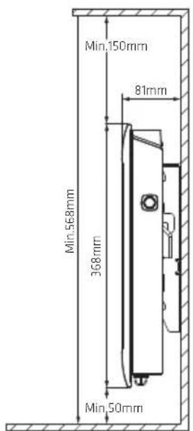
- WARNING: this appliance should be installed so that the bottom of the heater is at least 50 mm above the floor.
- Statement: The appliance is not to be placed immediately below a socket-outlet.
- Always turn off and unplug the appliance when not in use.
- Always unplug the appliance and ensure the appliance is completely cold before moving, cleaning, or storing it.
- When using this appliance – plug directly into the wall socket and not via extension cables or other adaptors as this may cause an overload.
- CAUTION – Some parts of this appliance can become very hot and cause burns. Particular attention has to be given where children and vulnerable people are present.
PRODUCT OVERVIEW
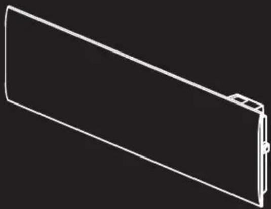
1.Body 2.Switch 3. Control panel 4. Wall bracket 5. Wall-mounting kits
| Description | Drawing QTY | |
| Screw 4 | ||
| 4Pla | ||
stic plug
INSTALLATION

| Model no. Watt A B | |||
| POPANW400 150mm | 46500W | ||
| POPANW600 | 600W | 210mm | 525mm |
| POPANW800/POPANW800B | 800W | 330mm | 645mm |
| POPANW1000/POPANW1000B | 1000W | 7380mm |


Fig.1
| Model no. Watt A B | |||
| POLISW800 490mm 103500W | |||
| 1000WP0205M100215mm | |||

Fig.2


Fig.3
To hang the heater on the wall:
- Choose a suitable installation location for the heater. Follow the minimum distances in all directions (Fig 1). Disassemble the wall bracket by loosening the screw (not screw off, only loosen) and sliding the metal pieces out of the hole. Take out the bracket by pulling it down.
- Verify that the bracket is perfectly horizontal with a spirit level and mark the location of holes on the wall. Drill holes in the wall for the pegs with a suitable drill bit. Insert the pegs into the holes, then screw the wall mount bracket securely onto the wall (Fig 2).
- Place the heater against the bracket. Fix the heater on the 2 downwards hooks. Pull the heater upwards whilst keeping it in the 2 lower hooks. Fix the heater on the 2 upwards hooks. Pull the heater down. Slide the 2 metal pieces on top into the hole, and fasten the screws to lock the wall mount bracket (Fig 3).
Use CONTROL PANEL

| Touch icon | Function |
| +/- | set the temperature, from 5°C to 35°C, increase/decrease by 1°C each step. |
| OK | shift modes (Manual, P1, P2, P3, P4, OF) or confirm. |
| M | enter setting menu or to cancel. |
OPERATION
- The first time you plug in, press the on/off switch, the appliance will show 19°C at manual mode as factory default setting.
Pressing the button will switch the device on or off. If the button is in the down position, the device is on (1).
If the button is in the up position, the device is off (0).

When the temperature of the environment is below the set temperature, the heater will start to heat the room, otherwise, no.
The heating indicator icon will light on only when the product is heating up. Temperature adjustment:
Press “+” or “-” to set temperature. Min. setting is 5°C, Max. is 35°C.
Pressing and holding "+" or "-" makes the adjustment faster.
In the event of a power failure, the heater will resume to work under the
- same mode and set temperature after the power is resumed.
Short press OK to shift among the following modes: manual (NR), P1, P2,
- P3, P4, OF. (After flashing 5 seconds, the display will show set temperature.)
Manual: the display will show , press “+” or “-” to select the temperature manually.
P1-P4 mode: the default programs are as below. Among them, P1 to P3 are fixed pre-set programs while P4 is a free weekly personalized program.
OF mode: the display shows OF. During this mode, the appliance doesn't heat up but clock settings are maintained.
| Weekly modes | P1 (5-2) | Monday-Friday | Saturday-Sunday | ||||
| P2 (6-1) | Monday-Saturday | Sunday | |||||
| P3 (7-0) | Monday-Sunday | ||||||
| P4 (0-7) | Monday-Sunday | ||||||
| Time and program setting | Event 2 heating cycles4 heating cycles | ||||||
| Time period | Comfort | ComfortEco | Eco Comfort Eco | ||||
| Time | 6:00-9:00 | 9:00-16:00 | 16:00-23:00 | 23:00-6:00 | 7:00-23:00 | 23:00-7:00 | |
| Factory setting | 21°C 17°C | 21°C 17°C | 21°C 17°C | ||||
- Short press or keep pressing the “+” / “-” icon to change the set temperature. Short press “+” / “-” to adjust the temperature, 1°C each step, the temperature range is from 5 to 35°C. Keep “+” / “-” pressed to increase/– decrease the temperature quickly.
- Setting menu
Short press "M" icon to enter or exit the setting menu.
The setting menu can be used to show the function list of the appliance: td: time setting
Pr: P4 (free weekly personalized program)
C: temperature calibration
LI: adjustment of screen brightness
AS: adaptive start function
Press “+” or “-” to select from td (time setting), Pr (P4 free weekly personalized program), C (temperature calibration), LI (adjustment of screen brightness).
The selected icon will flash.
Time setting
Press “M” to select “td”, and short press “OK” to enter the time setting interface. Press “+” / “-” to set the day of the week (choose from d1 to d7). Then press “OK” to save and enter the hour setting.
Press “+” / “-” to set the hour (choose from 0 to 23). Then press “OK” to save and enter the minute setting.
Press “+” / “-” to set the minute (choose from 00 to 59). Then press “OK” to save and go back to the previous working mode and temperature.
You cannot make any other adjustments before setting the day/time.
P4 free weekly personalized program
Short press "M" to select Pr. Short press "OK" to enter the Pr (P4) free weekly program setting interface (the default modifiable program is P4). You can select 2 set temperature points for each hour of the 24 hours of the day, and each day of the week: COMFORT(★) and ECO(★).
COMFORT(★) is the set temperature value; the temperature value of ECO (★) is 4°C lower than the set temperature value.
The default day is d1. You can press "+"/"-" to select from d1/d2/d3/d4/d5/d6/d7 (d1-Monday, d2-Tuesday, d3-Wednesday, d4-Thursday, d5-Friday, d6-Saturday, d7-Sunday). Press "OK" to confirm the day.
The display shows 0 to mean the first hour (0:00-0:59). Short press “+” to select comfort(★), “-” to select eco(★), or “OK” to keep the previous setting. After selecting the working mode for the 1st hour, the appliance will automatically move to the 2nd hour. Press “+” or “-” or “OK” to select the working mode of the 2nd hour, and enter the next hour setting. Repeat above until you select the working mode for the 24th hour (23 is displayed on the screen) setting. The heater will then automatically go back to the setting interface of day of the week.
After you finish setting the day, press "OK" to confirm and repeat the same operation for the rest of the days.
After you finish the setting of P4, the display will flash for 30 seconds and then go back to the setting menu with the display showing “Pr”. “Pr” will then flash for 10 seconds, and then the display will go back to the working mode interface.
To check the whole program of P4, keep “+” & “-” pressed for 5 seconds when the display shows “Pr”. The screen will show the whole program hour by hour for each day of the week.
Temperature calibration setting
Short press "M" to select "C". Short press "OK" to enter the C-temperature calibration setting interface.
“0” will be shown on the display as default. Press “+” / “-” to set the compensation temperature within ±5°C.
Example: the temperature setting on your heater is 24°C. The heater stops heating even though your thermometer says the temperature is only 22°C. In this case, choose the calibration value -2°C.
Adjustment of screen brightness:
Short press “M” to select LI. Press “OK” to enter LI-screen brightness setting interface. You can adjust the brightness of the screen. The default setting value is 3.
Press “+” / “-” to choose from grade 1 to 5. Grade 1 is the darkest while 5 is the brightest.
Adaptive start function:
Short press “M” to select “AS”. Press “OK” to enter Adaptive Start setting interface. The screen will show “on” or “oF”. Press “+” or “-” to change the selection. When “on” is selected, the Adaptive Start function is activated. When “oF” is selected, the function is deactivated. Default setting is “oF”. This feature measures the thermal inertia of the room and turns on the heaters in advance to ensure "comfort" temperature is reached at the set time. This function can turn on the appliance for heating maximum 2 hours in advance.
Remarks: This function applies for P1, P2, P3 programs only.
Window detector function
Press “+” & “OK” for 5 seconds to enter the window detector setting with “☐” flashing. The display will show “on” or “oF”. Press “+” or “-” to select. If “on” is selected, the window detector function is activated. When “oF” is selected, the window detector function will be deactivated. Press “OK” to save. After 5 seconds without operation, the heater will also automatically save the setting and return to previous working mode. The default factory setting is off.
When “on” is selected, the icon “☐” will show on the screen. When temperature decrease is detected, the appliance will enter anti-freeze mode (the screen shows 7°C with “☐” flashing). When temperature increase is detected, it will go back to previous working mode. You can press any button to return to the previous working mode.
Child lock
Press “M” & “-” for 5 seconds until the screen shows “CC”. The child lock is now activated. Repeat same operation to deactivate the child lock function. When child lock is activated, “CC” will flash 3 times and go back to temperature display. Press any icon on the control panel, the screen will show “CC” 3 times and go back to temperature display.
The child lock function will remain in function after resuming operation after a power failure.
Display Auto Off
Activate: press “-” & “OK” for 5 seconds. The screen will flash 3 times and activate the Display Auto Off function. The display switches off if there is no operation within 30 seconds. Press any icon to light the display on again. Deactivate: repeat the same operation to deactivate this function.
When the Display Auto Off function is activated, press and hold “OK” & “-” simultaneously for over 5 seconds. During the process, all icons on the display flash slowly until all icons on the display go off, then the Display Auto Off mode will be deactivated.
Memory function
After power switches off, the heater memorizes the working set temperature before the power failure and continues to work after power resumes. In the event of a power failure, the heater will keep the internal clock running for 24 hours. If the power is disconnected for more than 24 hours, when the power is turned on again, the heater will return to the last used temperature, and the internal clock will return to the default time and start running again. The screen will flash, indicating that there has been a power outage. The blinking state will continue until any button is pressed to cancel the blinking.
Heating icon
- When it is detected that the ambient temperature is lower than the set temperature and the heater needs to start working, the heating icon will light up. If the ambient temperature is detected to be higher than the set temperature, the heating icon will turn off.
- In standby state, the heating icon is not displayed.
Reset
Press and hold “+” and “M” at the same time for more than 5 seconds. The screen will show “rE”. The setting temperature will go back to factory default setting 19°C.
Wi-Fi connection
Insert the power plug and turn on the power switch. Choose "OF" mode by pushing the "OK" button until the "OF" symbol is displayed. Keep pressing
"OK" for more than 5 seconds and the icon "Wi-Fi" will flash.
Refer to the "Wi-Fi guide" for further instructions.
Troubleshooting
If the product does not operate or does not operate properly, first check the following list. If the reason for the malfunction is not in the following list, the product may have failed. At this time, it is recommended to send the product to the dealer or have it repaired.
| Problem SolutionPossible Cause | ||
| The mains plug is plugged, but the appliance does not work. | The main plug may not be correctly inserted into the mains power socket. | Check whether the plug is properly inserted into the mains power socket. |
| The heater suddenly stops during heating | The temperature exceeds the threshold of the thermal cut-off. | The system will automatically cut off the power supply.Cool the heater down before using again. |
CLEANING AND STORAGE
It is recommended that the heater be cleaned at least one time during the operating season in order to provide the optimum level of performance. ALWAYS TURN THE POWER SWITCH OFF AND UNPLUG THE HEATER BEFORE CLEANING.
Be sure to save the box for off-season storage.
- Turn the heater "OFF", unplug it and wait for the heater to cool down.
- Use a dry cloth to clean the external surfaces of the heater.
- Do not use any cleaning agents or detergents. • Never immerse the heater in water.
- Pack the heater in the original carton and store it in a cool and dry place.
Technical data
Frequency range: WiFi 2.4GHz (2.412-2.472GHz), RF Conducted Power: 6.5dBm
| Ref no. | 1926645 1926647 | 1926649/1926650 | 1926651/1926652 | 1930541 1930543 | ||
| Model no. | POPANW400 | POPANW600 | POPANW800/POPANW800B | POPANW1000/POPANW1000B | POLISW800 | POLISW1000 |
| Rated voltage | 220-240V~50-60Hz | 220-240V~50-60Hz | 220-240V~50-60Hz | 220-240V~50-60Hz | 220-240V~50-60Hz | 220-240V~50-60Hz |
| Rated power | 400W 600W | 800W 1000W | 800W 1000W | |||
| Class | II | II | II | II | II | II |
| IP rating | IP24 | IP24 | IP24 | IP24 | IP24 | IP24 |
| Model identifier(s): POPANW400 | |||||||
| Item Symbol | Value Unit | UnitItem | |||||
| Heat output | Type of heat input, for electric storage local space heaters only (select one) | ||||||
| Nominal heat output | Pnom | 0.4 kW | NA | manual heat charge control, with integrated thermostat | |||
| Minimum heat output (indicative) | Pmin | - | kW | manual heat charge control with room and/or outdoor temperature feedback | NA | ||
| Maximum continuous heat output | Pmax,c | 0.4 kW | electronic heat charge control with room and/or outdoor temperature feedback | NA | |||
| Auxiliary electricity consumption | fan assisted heat output | NA | |||||
| At nominal heat output | elmax | 0.000 | kW | Type of heat output/room temperature control (select one) | |||
| At minimum heat output | elmin | 0.000 No | kW | single stage heat output and no room temperature control | |||
| In standby mode el | SB | 0.0005 | kW | Two or more manual stages, no room temperature control | No | ||
| with mechanic thermostat room temperature control | No | ||||||
| with electronic room temperature control | No | ||||||
| electronic room temperature control plus day timer | No | ||||||
| electronic room temperature control plus week timer | Yes | ||||||
| Other control options (multiple selections possible) | |||||||
| room temperature control, with presence detection | No | ||||||
| room temperature control, with open window detection | Yes | ||||||
| with distance control option | Yes | ||||||
| with adaptive start control | No | ||||||
| with working time limitation | No | ||||||
| with black bulb sensor | No | ||||||
| Contact details | Power International AS, PO Box 523, N-1 471 Lørenskog, Norway | ||||||
| Model identifier(s): POPANW600 | ||||||
| Item Symbol | Value Unit | UnitItem | ||||
| Heat output | Type of heat input, for electric storage local space heaters only (select one) | |||||
| Nominal heat output | Pnom | 0.6 kW | NA | manual heat charge control, with integrated thermostat | ||
| Minimum heat output (indicative) | Pmin | - | kW | manual heat charge control with room and/or outdoor temperature feedback | NA | |
| Maximum continuous heat output | Pmax,c | 0.6 kW | electronic heat charge control with room and/or outdoor temperature feedback | NA | ||
| Auxiliary electricity consumption | fan assisted heat output | NA | ||||
| At nominal heat output | elmax | 0.000 | kW | Type of heat output/room temperature control (select one) | ||
| At minimum heat output | elmin | 0.000 No | kW | single stage heat output and no room temperature control | ||
| In standby mode el | SB | 0.0005 | kW | Two or more manual stages, no room temperature control | No | |
| with mechanic thermostat room temperature control | No | |||||
| with electronic room temperature control | No | |||||
| electronic room temperature control plus day timer | No | |||||
| electronic room temperature control plus week timer | Yes | |||||
| Other control options (multiple selections possible) | ||||||
| room temperature control, with presence detection | No | |||||
| room temperature control, with open window detection | Yes | |||||
| with distance control option | Yes | |||||
| with adaptive start control | No | |||||
| with working time limitation | No | |||||
| with black bulb sensor | No | |||||
| Contact details | Power International AS, PO Box 523, N-1 471 Lørenskog, Norway | |||||
| Model identifier(s): POPANW800/POPANW800B | ||||||
| Item Symbol | Value Unit | UnitItem | ||||
| Heat output | Type of heat input, for electric storage local space heaters only (select one) | |||||
| Nominal heat output | Pnom | 0.8 kW | NA | manual heat charge control, with integrated thermostat | ||
| Minimum heat output (indicative) | Pmin | - | kW | manual heat charge control with room and/or outdoor temperature feedback | NA | |
| Maximum continuous heat output | Pmax,c | 0.8 kW | electronic heat charge control with room and/or outdoor temperature feedback | NA | ||
| Auxiliary electricity consumption | fan assisted heat output | NA | ||||
| At nominal heat output | elmax | 0.000 | kW | Type of heat output/room temperature control (select one) | ||
| At minimum heat output | elmin | 0.000 No | kW | single stage heat output and no room temperature control | ||
| In standby mode el | SB | 0.0005 | kW | Two or more manual stages, no room temperature control | No | |
| with mechanic thermostat room temperature control | No | |||||
| with electronic room temperature control | No | |||||
| electronic room temperature control plus day timer | No | |||||
| electronic room temperature control plus week timer | Yes | |||||
| Other control options (multiple selections possible) | ||||||
| room temperature control, with presence detection | No | |||||
| room temperature control, with open window detection | Yes | |||||
| with distance control option | Yes | |||||
| with adaptive start control | No | |||||
| with working time limitation | No | |||||
| with black bulb sensor | No | |||||
| Contact details | Power International AS, PO Box 523, N-1 471 Lørenskog, Norway | |||||
| Model identifier(s): POPANW1 000/POPANW1 000B | ||||||
| Item Symbol | Value Unit | UnitItem | ||||
| Heat output | Type of heat input, for electric storage local space heaters only (select one) | |||||
| Nominal heat output | Pnom | 1.0kWNA | manual heat charge control, with integrated thermostat | |||
| Minimum heat output (indicative) | Pmin | - | kW | manual heat charge control with room and/or outdoor temperature feedback | NA | |
| Maximum continuous heat output | Pmax,c | 1.0kW | electronic heat charge control with room and/or outdoor temperature feedback | NA | ||
| Auxiliary electricity consumption | fan assisted heat output | NA | ||||
| At nominal heat output | elmax | 0.000 | kW | Type of heat output/room temperature control (select one) | ||
| At minimum heat output | elmin | 0.000No | kW | single stage heat output and no room temperature control | ||
| In standby mode el | SB | 0.0005 | kW | Two or more manual stages, no room temperature control | No | |
| with mechanic thermostat room temperature control | No | |||||
| with electronic room temperature control | No | |||||
| electronic room temperature control plus day timer | No | |||||
| electronic room temperature control plus week timer | Yes | |||||
| Other control options (multiple selections possible) | ||||||
| room temperature control, with presence detection | No | |||||
| room temperature control, with open window detection | Yes | |||||
| with distance control option | Yes | |||||
| with adaptive start control | No | |||||
| with working time limitation | No | |||||
| with black bulb sensor | No | |||||
| Contact details | Power International AS, PO Box 523, N-1 471 Lørenskog, Norway | |||||
| Model identifier(s): POLISW800 | ||||||
| Item Symbol | Value Unit | UnitItem | ||||
| Heat output | Type of heat input, for electric storage local space heaters only (select one) | |||||
| Nominal heat output | Pnom | 0.8 kW | NA | manual heat charge control, with integrated thermostat | ||
| Minimum heat output (indicative) | Pmin | - | kW | manual heat charge control with room and/or outdoor temperature feedback | NA | |
| Maximum continuous heat output | Pmax,c | 0.8 kW | electronic heat charge control with room and/or outdoor temperature feedback | NA | ||
| Auxiliary electricity consumption | fan assisted heat output | NA | ||||
| At nominal heat output | elmax | 0.000 | kW | Type of heat output/room temperature control (select one) | ||
| At minimum heat output | elmin | 0.000 No | kW | single stage heat output and no room temperature control | ||
| In standby mode el | SB | 0.0005 | kW | Two or more manual stages, no room temperature control | No | |
| with mechanic thermostat room temperature control | No | |||||
| with electronic room temperature control | No | |||||
| electronic room temperature control plus day timer | No | |||||
| electronic room temperature control plus week timer | Yes | |||||
| Other control options (multiple selections possible) | ||||||
| room temperature control, with presence detection | No | |||||
| room temperature control, with open window detection | Yes | |||||
| with distance control option | Yes | |||||
| with adaptive start control | No | |||||
| with working time limitation | No | |||||
| with black bulb sensor | No | |||||
| Contact details | Power International AS, PO Box 523, N-1 471 Lørenskog, Norway | |||||
| Model identifier(s): POLISW1 000 | ||||||
| Item Symbol | Value Unit | UnitItem | ||||
| Heat output | Type of heat input, for electric storage local space heaters only (select one) | |||||
| Nominal heat output | Pnom | 1.0kWNA | manual heat charge control, with integrated thermostat | |||
| Minimum heat output (indicative) | Pmin | - | kW | manual heat charge control with room and/or outdoor temperature feedback | NA | |
| Maximum continuous heat output | Pmax,c | 1.0kW | electronic heat charge control with room and/or outdoor temperature feedback | NA | ||
| Auxiliary electricity consumption | fan assisted heat output | NA | ||||
| At nominal heat output | elmax | 0.000 | kW | Type of heat output/room temperature control (select one) | ||
| At minimum heat output | elmin | 0.000No | kW | single stage heat output and no room temperature control | ||
| In standby mode el | SB | 0.0005 | kW | Two or more manual stages, no room temperature control | No | |
| with mechanic thermostat room temperature control | No | |||||
| with electronic room temperature control | No | |||||
| electronic room temperature control plus day timer | No | |||||
| electronic room temperature control plus week timer | Yes | |||||
| Other control options (multiple selections possible) | ||||||
| room temperature control, with presence detection | No | |||||
| room temperature control, with open window detection | Yes | |||||
| with distance control option | Yes | |||||
| with adaptive start control | No | |||||
| with working time limitation | No | |||||
| with black bulb sensor | No | |||||
| Contact details | Power International AS, PO Box 523, N-1 471 Lørenskog, Norway | |||||

This symbol on the product or in the instructions means that your electrical and electronic equipment should be disposed at the end of its life separately from your household waste. There are separate collection systems for recycling in the EU. For more information, please contact the local authority or your retailer where you purchased the product.
Power International AS, PO Box 523, N-1471 Lørenskog, Norway
Power Norge: https://www.power.no/kundeservice/ T: 21 00 40 00
Expert Danmark: https://www.expert.dk/kundeservice/ T: 70 70 17 07
Power Danmark: https://www.power.dk/kundeservice/ T: 70 33 80 80
Punkt 1 Danmark: https://www.punkt1.dk/kundeservice/ T: 70 70 17 07
Power Finland: https://www.power.fi/tuki/asiakaspalvelu/ T: 0305 0305
Power Sverige: https://www.power.se/kundservice/ T: 08 517 66 000
SAFETY INSTRUCTIONS

1. Main body 2. Switch 3. Control panel 4. Wall bracket 5. Set for wall mounting
| Beskrivelse | Tegning Antall | |
| Skrue 4 | ||
| 4Pla | ||
plug
INSTALLATION


| Modellnr. Watt A B | |||
| POPANW400 150mm | 46500W | ||
| POPANW600 | 600W | 210mm | 525mm |
| POPANW800/POPANW800B | 800W | 330mm | 645mm |
| POPANW1000/POPANW1000B | 1000W | 420mm | 735mm |


Fig.1
| Modellnr. Watt A B | |||
| POLISW800 490mm | 1835Wm | ||
| 1000WP0205Wm10005mm | |||

Fig.2


Fig.3

Setting temperature calibration:


| Mallinumero wattia A B | |||
| POPANW400 150mm 46500W | |||
| POPANW600 | 600W | 210mm | 525mm |
| POPANW800/POPANW800B | 800W | 330mm | 645mm |
| POPANW1000/POPANW1000B | 1000W | 7320mm |


| Mallinumero wattia A B | ||
| POLISW800 800W | 490mm | 1035mm |
| 1000WP | 6705W10005mm |
Fig.1
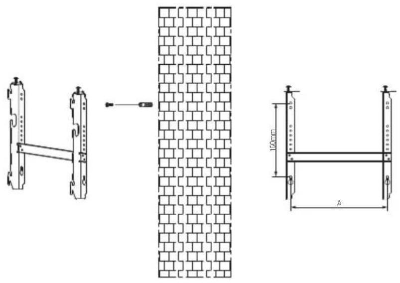
Fig.2


Fig.3

| Modelnummer Watt A B | |||
| POPANW400 150mm 46500W | |||
| POPANW600 | 600W | 210mm | 525mm |
| POPANW800/POPANW800B | 800W | 330mm | 645mm |
| POPANW1000/POPANW1000B | 1000W | 7380mm | |


Fig.1
| Modelnummer Watt A B | ||
| POLISW800 800W | 490mm | 1035mm |
| 1000WP6705W100215mm | ||

Fig.2


Fig.3


| Modellnr. Watt A B | |||
| POPANW400 150mm | 46500W | ||
| POPANW600 | 600W | 210mm | 525mm |
| POPANW800/POPANW800B | 800W | 330mm | 645mm |
| POPANW1000/POPANW1000B | 1000W | 7380mm |
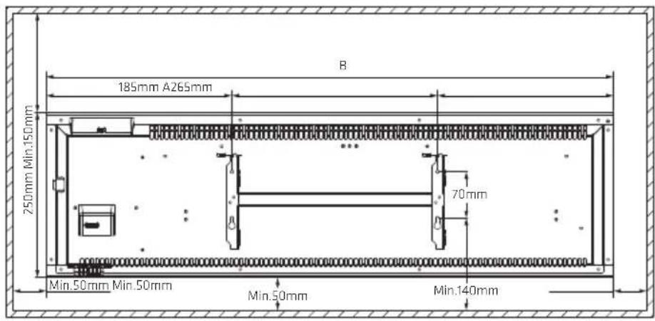

Fig.1
| Modellnr. Watt A B | |||
| POLISW800 800W | 490mm | 1035mm | |
| 1000WP6705W100215mm | |||

Fig.2


Fig.3


- GB
- NO
- READ AND SAVE THESE IMPORTANT SAFETY INSTRUCTIONS
- TO HANG THE HEATER ON THE WALL
- USE CONTROL PANEL
- OPERATION
- TIME SETTING
- P4 FREE WEEKLY PERSONALIZED PROGRAM
- TEMPERATURE CALIBRATION SETTING
- ADJUSTMENT OF SCREEN BRIGHTNESS
- ADAPTIVE START FUNCTION
- WINDOW DETECTOR FUNCTION
- CHILD LOCK
- DISPLAY AUTO OFF
- MEMORY FUNCTION
- HEATING ICON
- RESET
- WI-FI CONNECTION
- TROUBLESHOOTING
- CLEANING AND STORAGE
- TECHNICAL DATA
- SAFETY INSTRUCTIONS
- INSTALLATION
- SETTING TEMPERATURE CALIBRATION
Brand : Point
Model : POPANW1000
Category : Heating