
DTP T UWP 4K 232 D - HDMI Transmitter Extron - Free user manual and instructions
Find the device manual for free DTP T UWP 4K 232 D Extron in PDF.


| Product Type | Wallplate Transmitter/Receiver for HDMI over Twisted Pair |
| Model | DTP T UWP 4K 232 D |
| Brand | Extron |
| Dimensions (H x W x D) | 2.75" x 1.65" x 1.25" (7.0 cm x 4.2 cm x 3.2 cm) |
| Weight | 0.3 lb (136 g) |
| Power Supply | Power over Ethernet (PoE) from DTP switcher or compatible injector |
| Power Consumption | 4.8 W |
| Video Resolution | Up to 4K @ 60 Hz (4:4:4) |
| Maximum Distance | 330 ft (100 m) over CATx cable |
| Signal Types | HDMI, bidirectional RS-232, IR |
| Connectors | 1 HDMI input, 1 RJ-45 output, 1 captive screw RS-232 |
| HDCP Support | Yes, HDCP 2.3 compliant |
| Mounting | Decora-style wallplate |
| Operating Temperature | 32 to 113°F (0 to 45°C) |
| Compliance | CE, FCC Class A, c-UL, UL |
| Maintenance | Wipe with a soft, dry cloth. No user-serviceable parts. |
| Safety | Complies with safety standards; use only with certified PoE sources. |
| Spare Parts & Repairability | No spare parts available. Contact Extron support for service. |
| General Information | Extron DTP T UWP 4K 232 D is a transmitter/receiver for extending HDMI, RS-232, and IR over a single CATx cable. Ideal for use with DTP switchers. |
Frequently Asked Questions - DTP T UWP 4K 232 D Extron
User questions about DTP T UWP 4K 232 D Extron
0 question about this device. Answer the ones you know or ask your own.
Ask a new question about this device
Download the instructions for your HDMI Transmitter in PDF format for free! Find your manual DTP T UWP 4K 232 D - Extron and take your electronic device back in hand. On this page are published all the documents necessary for the use of your device. DTP T UWP 4K 232 D by Extron.
USER MANUAL DTP T UWP 4K 232 D Extron
DTP T UWP 4K D Series
HDMI Twisted Pair Extender Transmitters
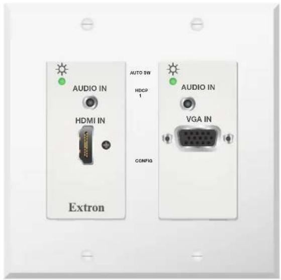
User Guide HDMI Transmitters
68-3157-01, Rev. C
Safety Instructions
Safety Instructions • English

WARNING: This symbol, when used on the product, is intended to alert the user of the presence of uninsulated dangerous voltage within the product's enclosure that may present a risk of electric shock.
ATTENTION: This symbol, when used on the product, is intended to alert the user of important operating and maintenance (servicing) instructions in the literature provided with the equipment.
For information on safety guidelines, regulatory compliances, EMI/EMF compatibility, accessibility, and related topics, see the Extron Safety and Regulatory Compliance Guide, part number 68-290-01, on the Extron website, www.extron.com.
All trademarks mentioned in this guide are the properties of their respective owners. The following registered trademarks ( ® ), registered service marks ( SM ), and trademarks ( TM ) are the property of RGB Systems, Inc. or Extron (see the current list of trademarks on the Terms of Use page at www.extron.com):
| Registered Trademarks (®) |
| Extron®, Cable Cubby®, ControlScript®, CrossPoint®, DTP®, eBUS®, EDID Manager®, EDID Minder®, eLink®, Everlast®, Flat Field®, FlexOS®, Glitch Free®, GlobalViewer®, Global Configurator®, Global Scripter®, Hideaway®, HyperLane®, IP Intercom®, IP Link®, Key Minder®, LinkLicense®, LockIt®, MediaLink®, MediaPort®, NAV®, NetPA®, PlenumVault®, PoleVault®, PowerCage®, PURE3®, Quantum®, ShareLink®, Show Me®, StudioStation®, SoundField®, SpeedMount®, SpeedSwitch®, System INTEGRATOR®, TeamWork®, TouchLink®, V-Lock®, VN-Matrix®, VoiceLift®, WallVault®, WindoWall®, XPA®, XTP®, XTP Systems®, and ZipClip® |
| Registered Service Mark (SM) : S3 Service Support Solutions |
| Trademarks (TM) |
| AAP TM , AFL TM - Accu-RATE Frame Lock, ADSP TM - Advanced Digital Sync Processing, AVEdge TM , CableCover TM , CDRS TM - Class D Ripple Suppression, Codec Connect TM , ConferenceShare TM , DDSP TM - Digital Display Sync Processing, DMI TM - Dynamic Motion Interpolation, Driver Configurator TM , DSP Configurator TM , DSP Configurator Pro TM , DSVP TM - Digital Sync Validation Processing, EQIP TM , FastBite TM , Flex55 TM , FOX TM , FOXBOX TM , InstaWake TM , IP Intercom HelpDesk TM , MAAP TM , MicroDigital TM , Opti-Torque TM , PendantConnect TM , ProDSP TM , QS-FPC TM - QuickSwitch Front Panel Controller, Room Agent TM , Scope-Trigger TM , SIS TM - Simple Instruction Set, Skew-Free TM , SpeedNav TM , Triple-Action Switching TM , True4K TM , True8K TM , Vector TM 4K, WebShare TM , XTRA TM , and ZipCaddy TM |
FCC Class A Notice
This equipment has been tested and found to comply with the limits for a Class A digital device, pursuant to part 15 of the FCC rules. The Class A limits provide reasonable protection against harmful interference when the equipment is operated in a commercial environment. This equipment generates, uses, and can radiate radio frequency energy and, if not installed and used in accordance with the instruction manual, may cause harmful interference to radio communications. Operation of this equipment in a residential area is likely to cause interference. This interference must be corrected at the expense of the user.
ATTENTION: The Twisted Pair Extension technology works with shielded twisted pair (STP) cables only.
To ensure FCC Class A and CE compliance, STP cables and STP connectors are also required.
For more information on safety guidelines, regulatory compliances, EMI/EMF compatibility, accessibility, and related topics, see the Extron Safety and Regulatory Compliance Guide on the Extron website.
Conventions Used in this Guide
Notifications
The following notifications are used in this guide:
CAUTION: Risk of minor personal injury.
NOTE: A note draws attention to important information.
Software Commands
Commands are written in the fonts shown here:
^AR Merge Scene,,Op1 scene 1,1^B 51 ^W^C
[01] R 0004 00300 00400 00800 00600 [02] 35 [17] [03]
Esc X1 *X17 *X20 *X23 *X21 CE←
NOTE: For commands and examples of computer or device responses mentioned in this guide, the character “0” is used for the number zero and “0” is the capital letter “o.”
Computer responses and directory paths that do not have variables are written in the font shown here:
Reply from 208.132.180.48: bytes=32 times=2ms TTL=32
C:\Program Files\Extron
Variables are written in slanted form as shown here:
ping XXX.XXX.XXX.XXX -t
SOH R Data STX Command ETB ETX
Selectable items, such as menu names, menu options, buttons, tabs, and field names are written in the font shown here:
From the File menu, select New.
Click the 0K button.
Specifications Availability
Product specifications are available on the Extron website, www.extron.com.
Extron Glossary of Terms
A glossary of terms is available at http://www.extron.com/technology/glossary.aspx.
Contents
Introduction....1
About this Guide....1
Terms Used in this Guide....1
About the and DTP T UWP 4K D Extenders....1
Twisted Pair Cable Advantages ....1
Control Communications....2
Transmission Distance 2
Features 2
Installation and Operation 4
Mounting the Transmitter 4
UL and Safety Guidelines....4
Site Preparation and Wall Box Installation 5
Mud Ring Installation....6
Final Installation 6
DTP T UWP 4K D Connections ....7
Front Panel....7
Rear Panel 8
Twisted Pair Recommendations for DTP Communication....9
Supported Cables 9
Cable Recommendations....9
Power Supply Wiring 10
RS-232 Connector Wiring....11
Remote RS-232 and Contact Closure Connector 11
Over DTP RS-232 Connector 11
Operation....12
Transmitter LEDs 12
System Operation 12
Audio Configuration....13
EDID Minder 13
SIS Command Control 14
Contact Closure Control 14
Simple Instruction Set Control....14
Host-to-Extender Communications 14
Extender-Initiated Messages....14
Error Responses 15
Timeout 15
Using the Command and Response Table....15
Symbol Definitions 15
Command and Response Table for SIS Commands....17
Configuration Software.... 20
Installing the Software/Firmware 20
Using PCS with the DTP T UWP 4K D Transmitters ....22
Device Discovery Panel 22
AV Controls 23
Input/Output Configuration 24
EDID Minder....25
Image Settings 25
Audio Configuration....26
General Settings 26
Device List....27
Software List 28
Reference Information 31
Decorator-Style Wallplate Template Dimensions....31
Best Practices for Cleaning Your Extron Products 32
Extron Warranty.... 33
Introduction
- About this Guide
• About the and DTP T UWP 4K D Extenders - Features
About this Guide
This guide provides instructions for experienced, professional installers to install, operate, and configure the Extron DTP T UWP 4K D series of High-Definition Multimedia Interface (HDMI®) and VGA Extenders.
Terms Used in this Guide
The terms “extender” and “transmitter” are used interchangeably in this guide to refer to all of the DTP T UWP 4K D models.
About the and DTP T UWP 4K D Extenders
The Extron DTP T UWP 4K 232 D and DTP T UWP 4K 332 D extenders are a series of HDMI and VGA transmitters (see figure 1) that are housed in enclosures that can be mounted in Underwriters Laboratories (UL) standard wall boxes with decorator-style faceplates. Paired with a compatible DTP 230 or 330 receiver, they extend the usable distance of HDMI digital video, VGA analog video, and RS-232 control signals over one shielded twisted pair (STP) cable. The extenders also route and embed audio.
![graph TD A["Extron DTP T UWP 4K 232 D Tx Transmitter"] --> B["IN1608"] B --> C["XTP DTP 24 Cable 230'"] B --> D["DTP HDMI 230 Rx"] D --> E["HDMI"] D --> F["Projector"] G["IPC P 505"] --> H["Ethernet"] H --> I["Network"] I --> J["TLP 1000TV"]](/content/2026/07/1412903/images/97cd9acc6bcb266dd36f9f8f09b4300c42e32b76a4eacc78c91c7fe1f9ccf9ab.jpg)
Figure 1. Typical Transmitter and Receiver Application
DTP T UWP 4K D systems consist of a transmitter (Tx) and a receiver (Rx). The transmitters and corresponding compatible receivers are sold separately. Each purchased transmitter is shipped with a single external desktop 12 VDC power supply that accepts 100 to 240 VAC, 50-60 Hz input. A single power supply connected to either the transmitter or a compatible receiver can power both units through the twisted pair cable that links the units.
Twisted Pair Cable Advantages
Twisted pair cable is much smaller, lighter, more flexible, and less expensive than coaxial or HDMI cable. These transmitter and receiver twisted pair (TP) products make cable runs simpler and less cumbersome. Termination of the cable with RJ-45 connectors is simple, quick, and economical (see Twisted Pair Recommendations for DTP Communication on page 9 for more information).
NOTE: Do not use Extron UTP23SF-4 Enhanced Skew-Free AV UTP cable or STP201 cable to link the transmitter and receiver. The DTP T UWP 4K D series does not work properly with these cables.
Control Communications
The RS-232 communications are pass-through only. The transmitter and receiver do not generate or respond to these signals.
Transmission Distance
The maximum transmission distance is determined by the resolution of the signal and the twisted pair cable, graphics card, and display used in the system.
- DTP T UWP 4K 232 D transmitters can transmit 720p, 1080i or 1080p HDTV video, and 4K signals up to 230 feet (70 meters) over STP cable.
- DTP T UWP 4K 332 D transmitters can transmit 720p, 1080i or 1080p HDTV video, and 4K signals up to 330 feet (100 meters) over STP cable.
Features
- Transmits HDMI, VGA, control, and analog audio up to 330 feet (100 meters) over a shielded CATx cable — The DTP T UWP 4K 232 D provides high reliability and maximum performance on an economical and easily installed cable infrastructure.
- Inputs: One HDMI, one VGA on 15 pin HD, two 3.5 mm stereo mini jacks for audio
• Output: One DTP 330 twisted pair output on RJ 45
- Auto switching between inputs — Auto switching allows for simple, unmanaged installation in locations such as in a lectern or floor box. When multiple inputs are active, the highest numbered input with an active video signal takes priority.
- Supports computer and video resolutions up to 4K — Supports 4K/60 4:2:0 and 4K/30 4:4:4, maintaining superior image quality at the highest resolutions.
- Analog stereo audio embedding — Analog stereo audio signals can be selectively embedded onto the digital video output signal and transported over DTP. The HDMI can be set to pass the embedded digital audio, embed the analog audio, or to automatically embed the analog audio when no digital audio is detected. For 4K HDMI video, only the original digital audio may be switched through the DTP output.
- Remote power capability — For simplified installation, the transmitter can be remotely powered by a DTP enabled product over the twisted pair connection.
- Extron XTP DTP 24 shielded twisted pair cable is strongly recommended for optimal performance.
- Compatible with CATx shielded twisted pair cable — The DTP T UWP 4K 232 D fully supports a maximum transmission distance of 330 feet (100 meters) for all compatible resolutions when used with CATx shielded twisted pair cable. Shielded twisted pair cabling with solid center conductor sizes of 24 AWG or better is recommended for optimal performance.
- Independent analog audio inputs — The DTP T UWP 4K 332 D provides two independent stereo analog audio connections for simultaneous transmission over the same shielded twisted pair cable.
- Supported HDMI specification features include data rates up to 10.2 Gbps, 3D, and HD lossless audio formats.
- Supports multiple embedded audio formats — The DTP T UWP 4K 332 D is compatible with a broad range of multi channel audio signals, providing reliable operation with HDMI sources.
- Bidirectional RS 232 pass through for AV device control — Bidirectional RS 232 control signals can be transmitted alongside the video signal, allowing remote AV devices to be controlled without the need for additional cabling.
- Digital conversion of analog input signals — Analog signals are digitized, ensuring that a reliable, high quality digital video signal is sent to the output destination.
- HDCP compliant — Ensures display of content-protected media and interoperability with other HDCP-compliant devices.
- User-selectable HDCP authorization — Allows the unit to appear HDCP compliant or non HDCP compliant to the connected source, which is beneficial if the source automatically encrypts all content when connected to an HDCP-compliant device. Protected material is not passed in non HDCP mode.
- EDID Minder automatically manages EDID communication between connected devices — EDID Minder ensures that all sources power up properly and reliably output content for display.
- HDMI to DVI Interface Format Correction — Automatically enables or disables embedded audio and InfoFrames, and sets the correct color space for proper connection to HDMI and DVI displays.
- Automatic color bit depth management — Automatically adjusts color bit depth based on the display EDID, preventing color compatibility conflicts between source and display.
- Compatible with all DTP 330 Series receivers and DTP 330 enabled products — Enables mixing and matching with desktop and wallplate receivers, as well as other DTP 330 enabled products to meet application requirements.
- RS 232 control port — Enables the use of serial commands for integration into a control system. Extron products use the SIS - Simple Instruction Set command protocol, a set of basic ASCII commands that allow for quick and easy programming.
- Contact closure control port — Can be used for external control of input switching.
- Front panel USB configuration port.
- LED indicators for signal presence, HDCP, and power — Provides visual indication of system status for real time feedback and monitoring of key performance parameters.
- RJ 45 signal and link LED indicators for DTP port — Provides a means for validating signal flow and operation, allowing quick identification of connectivity issues.
- Easy setup and commissioning with Extron PCS - Product Configuration Software — Conveniently configure multiple products using a single software application.
- Mounts in an included two-gang decorator-style wallplate — The two gang decorator-style wallplate is available in black or white to blend with a wide range of environments.
- External Extron Everlast power supply included — Provides worldwide power compatibility with high demonstrated reliability and low power consumption.
- Extron Everlast Power Supply is covered by a 7 year parts and labor warranty.
Installation and Operation
This section describes the installation and the operation of the extenders, including:
- Mounting the Transmitter
• Power Supply Wiring
• DTP T UWP 4K D Connections
• RS-232 Connector Wiring
• Twisted Pair Recommendations for DTP Communication
- Operation
Mounting the Transmitter
ATTENTION:
The transmitters can be installed in a two-gang electrical wall box, or with a mud ring with a decorator-style wallplate cover (supplied).
UL and Safety Guidelines
The following UL guidelines pertain to the installation of the decorator-style wallplate transmitters into a wall or furniture.
CAUTION:
ATTENTION :
Site Preparation and Wall Box Installation
Choose a location that allows cable runs without interference. Allow enough depth for both the wall box and the cables. Install the cables into the wall, furniture, or conduits before installing the wallplate.
NOTE: The extender units are very deep and have connectors on the back side. Extron recommends a 2-gang wall box with a depth of at least 3.0 inches (7.6 cm) to accommodate the connectors and cables.
To install a new wall box, perform steps 1 through 9. If a suitable wall box is already installed, perform steps 6 through 9 on the next page. UL Listed wall boxes are recommended.
- If a wall box is not available to use for a template, use the Decorator-Style Wallplate Template Dimensions on page 31 to create a template. If installing directly into furniture, cut out the center portion of the template.
- Place the wall box (or the full size template) against the installation surface, and mark the opening guidelines.
- Cut out the material from the marked area.
- Insert the wall box into the opening. The rear connectors on the box or wallplate should fit easily into the opening. Enlarge or smooth the edges of the opening if needed.
- Secure the wall box with nails or screws, leaving the front edge flush with the outer wall or furniture surface (see figure 2).
NOTES:
- If attaching the wall box to wood, use four #8 or #10 screws or 10-penny nails. A minimum of 0.5 inch (1.3 cm) of screw thread must penetrate the wood.
- If attaching the wall box to metal studs or furniture, use four #8 or #10 self-tapping sheet metal screws or machine bolts with matching nuts.

Figure 2. Installing the Wall Box and Mounting the Unit
- Feed the twisted pair cables and, if applicable, the power cables through the opening and through the wall box punch-out holes, securing them with cable clamps to provide strain relief.
NOTES:
- In order to fit in the wall box, the twisted pair cables and RJ-45 connectors should not have a boot installed.
-
One power supply can power both the transmitter and the receiver, so only one unit needs a power supply (see Power Supply Wiring on page 10).
-
Trim back and insulate exposed cable shields with heat shrink to reduce the chance of short circuits. To prevent short circuits, the outer foil shield can be cut back to the point where the cable exits the cable clamp.
- Connect the cables to the rear of the unit (see figure 6 on page 9 for port details).
- Connect front panel devices (see Front Panel on page 7 for port details), restore the power supply, and test the transmitter and receiver system. Make any cabling adjustments before final installation, as the cables will be inaccessible afterwards.
Mud Ring Installation
- Using the mud ring as a guide, mark the edges and cut out the material within the marked area.
- Insert the mud ring into the opening, rotate and secure the locking arms with the supplied screws shown in figure 3.
- Follow steps 6 through 9 of Site Preparation and Wall Box Installation on page 5, and Final Installation on page 6.
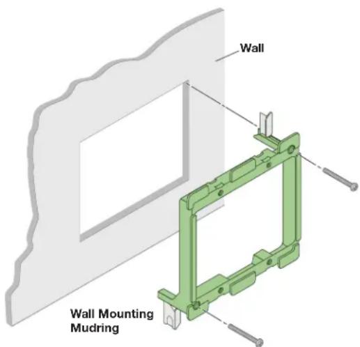
Figure 3. Installing the Mud Ring
Final Installation
After testing and making any adjustments, do the following:
- At the power outlet, unplug the power supply.
NOTE: One power supply can power both the transmitter and the receiver (see Power Supply Wiring on page 10).
- Mount the transmitter into the wall box or mud ring and attach the supplied decorator-style faceplate to the unit (see figure 2 on page 5).
- At the power outlet, reconnect the power supply. This powers up both units.
DTP T UWP 4K D Connections
Front Panel
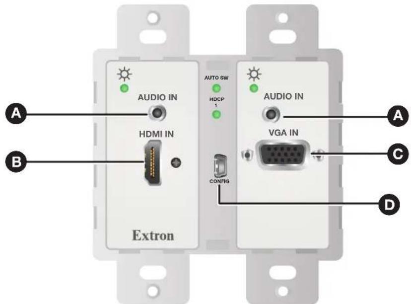
Figure 4. DTP T UWP 4K D Front Panel Ports
Audio input — Connect an unbalanced stereo audio source to this 3.5 mm mini stereo jack (see Audio Configuration on page 13 for embedded audio details).
B HDMI input — Connect an HDMI cable between this port and the HDMI output port of the digital video source.
© VGA input — Connect a VGA cable between this port and the output port of the video source.
D Mini USB port — Connect a male USB Mini-B cable to this port for SIS and PCS configuration and firmware updates.
Rear Panel

Figure 5. DTP T UWP 4K D Rear Panel Connectors
A DC power input — Plug the included external 12 VDC power supply into either this 2-pole port (see Power Supply Wiring on page 10 to wire the power connector) or the power input port on the receiver (see the user guide of your receiver for more information).
Over DTP control port — Connect an RS-232 device to this 3-pole, 3.5 mm captive screw port for pass-through RS-232 control (see RS-232 Connector Wiring on page 11 to properly wire the RS-232 connector).
Remote (RS-232 and contact closure) control port — Connect an RS-232 device, contact closure device, or both to this 5-pole, 3.5 mm captive screw port to control switching on the unit (see RS-232 Connector Wiring to properly wire the Remote connector).
- RS-232 — To control the unit through this port, connect an RS-232 device and configure it as follows: 9600 baud rate, 8 data bits, 1 stop bit, no parity.
- Contact — Momentarily short pin 1 or 2 to ground (G) to select the corresponding input.
D Grounding screw — Connect a grounding wire from this screw to the gang box chassis to safely ground the unit.
E DTP Out port — Connect one end of the twisted pair cable to the RJ-45 port on the transmitter (see Twisted Pair Recommendations for DTP Communication on page 9 to properly wire the RJ-45 connectors). Connect the opposite end of the cable to the appropriate receiver.
ATTENTION:
F Reset button — To perform a factory reset, use a small screwdriver to press and hold the recessed button for 6 seconds while the extender is running.
Twisted Pair Recommendations for DTP Communication
Use the following pin configuration for both ends of the shielded twisted pair cables.

Figure 6. Twisted Pair Cable Configuration
Supported Cables
The extenders are compatible with shielded twisted pair cable (F/UTP, SF/UTP, and S/FTP).
ATTENTION:
Cable Recommendations
Extron recommends using the following practices to achieve full transmission distances and reduce transmission errors.
- Use the following Extron XTP DTP 24 SF/UTP cables and connectors for the best performance:
• XTP DTP 24/1000 Non-Plenum 1000' (305 m) spool
• XTP DTP 24P/1000 Plenum 1000' (305 m) spool
• XTP DTP 24 Plug Package of 10
- If not using XTP DTP 24 cable, at a minimum, Extron recommends 24 AWG, solid conductor, STP cable with a minimum bandwidth of 400 MHz.
- Terminate cables with shielded connectors to the TIA/EIA-T568B standard.
- Limit the use of more than two pass-through points, which may include patch points, punch down connectors, couplers, and power injectors. If these pass-through points are required, use shielded couplers and punch down connectors.
NOTE: When using shielded twisted pair cable in bundles or conduits, consider the following:
- Do not exceed 40% fill capacity in conduits.
- Do not comb the cable for the first 20 meters, where cables are straightened, aligned, and secured in tight bundles.
- Loosely place cables and limit the use of tie wraps or hook-and-loop fasteners.
- Separate twisted pair cables from AC power cables.
Power Supply Wiring
Figure 7 shows how to wire the connector.

Figure 7. Power Connector Wiring
NOTES:
- Only one power supply is required for both the transmitter and receiver. A single power supply connected to either unit in the pair powers both units.
- A power supply is included with each individually-packaged transmitter.
- Do not tin the power supply leads before installing them in the direct insertion connector. Tinned wires are not as secure in the connectors and could be pulled out.
CAUTION: The wires must be kept separate while the power supply is plugged in. Remove power before wiring.
NOTE: Do not tin the wires before installing them in the direct insertion connector. Tinned wires are not as secure in the connectors and could be pulled out.
Remote RS-232 and Contact Closure Connector
Wire the rear Remote RS-232 and contact closure connector as shown in figure 8.
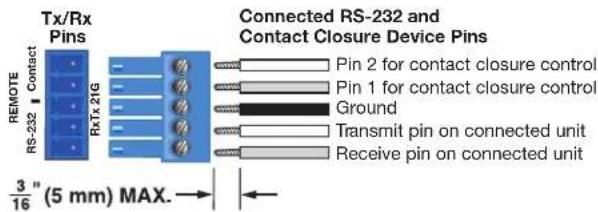
Figure 8. RS-232 and Contact Closure Connector Wiring
Over DTP RS-232 Connector
Wire the rear Over DTP RS-232 connector as shown in figure 9.

Figure 9. Over DTP Connector Wiring
Operation

Figure 10. Transmitter LED Indicators
Transmitter LEDs
Power LEDs — Two-color front panel LEDs on the transmitters light to indicate signal and power status as follows:
- Amber — The unit is receiving power but there is no signal on the associated input.
• Green — The unit is receiving power and a signal is present on the associated input.
NOTE: Both inputs on the transmitters have their own separate LEDs.
B Auto Switch LED — Lights steadily when auto switch is active (see Contact on page 8).
© HDCP LEDs — Lights steadily when HDMI input has been authenticated on the source device.
System Operation
After the transmitter, the receiver, and their connected devices are powered up, the system is fully operational. If any problems are encountered, ensure all cables are routed and connected properly.
NOTES:
- Ensure that the video source and display are properly connected to the transmitter and receiver pair, and that the transmitter, the receiver, and the display have power applied before power is applied to the video source. If all other devices are not turned on before the video source, the image may not appear.
- Input switching can be performed only via auto switching, RS-232, USB, or contact closure through the rear panel connectors.
Audio Configuration
The DTP T UWP 4K D series can embed analog audio inputs onto the digital video output. Use Extron Configuration Software on page 20 or SIS Command Control on page 14 to select the desired embedded audio mode.
NOTE: If no VGA or HDMI signal is present, analog audio will be transported over the DTP connection to the analog audio output of the receiver.
When an input is selected, audio transport over HDMI can be configured to operate in one of three modes. Each input can be configured individually for any of the three modes.
- Transport embedded digital audio (default) — The embedded digital audio content on the digital video input is transported. Analog audio is still separate from the embedded digital audio on the HDMI signal and transported simultaneously over the DTP output, not embedded onto the digital output.
- Embed analog audio input — The analog audio input is always embedded to the digital output, replacing whatever content is already present on the embedded digital audio. Analog audio is also transported over the DTP output as a simultaneous output.
- Auto select between analog audio and digital audio — When both analog audio and embedded digital audio on HDMI are present, embedded digital audio on the HDMI signal takes priority. Analog audio is transported simultaneously with the embedded digital audio content that is already present on the DTP output.
EDID Minder
EDID Minder ensures that source devices connected to the DTP T UWP 4K D inputs continually recognize the EDID of a sink device, even if a sink is not physically connected. By default, the EDID on the VGA input is configured for 1920x1080 @ 60 Hz, and the EDID on the HDMI input is configured for 1080p @ 60 Hz with 2-channel audio.
EDID can be configured further using PCS software (see EDID Minder on page 25).
SIS Command Control
This section includes:
- Contact Closure Control
• Simple Instruction Set Control
• Command and Response Table for SIS Commands
The DTP T UWP 4K D series transmitters can be remotely controlled via the front panel configuration (USB) port and the rear panel Remote RS-232 and Contact ports.
Contact Closure Control
The rear panel Remote port provides a way to select an input to the extender using a remote contact closure device. For contact closure pin assignments, see Contact on page 8.
To select a different input number using a contact closure device, momentarily short the pin for the desired input number to ground. To force one of the inputs to be always selected, leave the short to ground in place.
Simple Instruction Set Control
The DTP T UWP 4K D series of extenders can be remotely controlled using SIS commands from a host device such as a computer or control system via its rear panel Remote RS-232 port (see figure 5, © on page 8) or front panel Configuration (USB) port (see figure 4, Ⓓ on page 7).
The default serial port protocol of the RS-232 port is as follows:
• 9600 baud • No parity • 8-bit
- No flow control • 1 stop bit
Host-to-Extender Communications
SIS commands consist of one or more characters per field. No special characters are required to begin or end a command character sequence. When a command is valid, the extender executes the command and sends a response to the host device. All responses from the extender to the host end with a carriage return and a line feed (CR/LF = ←), which signals the end of the response character string. A string is one or more characters.
Extender-Initiated Messages
When a local event occurs, such as a front panel operation, loss or restoration of an input signal, or an error condition, the extender responds by sending a message to the host. Examples of the extender-initiated messages are listed below:
© Copyright 20yy, Extron Electronics DTP T UWP 232 D, Vx.xx, 60-nnnn-nn
The extender issues the copyright message when it first powers on.
• 20yy is the copyright year.
- Vx.xx is the firmware version number.
- 60-nnnn-nn is the part number.
Inn All←
The extender also sends the Inn message whenever the selected input is changed.
- n is the input number.
• 0 in the n field indicates no input is selected.
Error Responses
When the extender receives a valid SIS command, it executes the command and sends a response to the host device. If the extender is unable to execute the command because the command is invalid or it contains invalid parameters, the extender returns an error response to the host. The error response codes are:
E01 — Invalid input number
E06 — Invalid channel change
E10 — Invalid command
E13 — Invalid parameter
E14 — Not valid for this configuration
E17 — Invalid command for signal type
Timeout
Pauses of 10 seconds or longer between command ASCII characters result in a timeout. The command operation is aborted with no other indication.
Using the Command and Response Table
The Command and Response Table for SIS Commands begins on page 17. Symbols are used throughout the table to represent variables in the command and response fields. Command and response examples are shown throughout the table. The ASCII to HEX conversion table below is for use with the command and response table.
NOTE: Upper and lowercase text can be used interchangeably unless otherwise stated.
| ASCII to Hex Conversion Table Esc 1B CR ∅D LF ∅A | |||||||||||||
| Space → | 20 | ! | 21 | " | 22 | # | 23 | $ 24 | % | 25 | & | 26 | ' 27 |
| ( 28 ) | 29 | * | 2A | + | 2B , 2C | - | 2D | • | 2E / 2F | ||||
| 0 30 | 31 | 2 | 32 | 3 | 33 | 4 34 | 5 | 35 | 6 | 36 7 37 | |||
| 8 38 | 9 39 : | 3A ; 3B < 3C = 3D > 3E ? 3F | |||||||||||
| @ 40 A | 41 B | 42 C 43 D 44 E 45 F 46 G 47 | |||||||||||
| H 48 I | 49 J | 4A K 4B L 4C M 4D N 4E O 4F | |||||||||||
| P 50 Q | 51 R | 52 S 53 T 54 U 55 V 56 W 57 | |||||||||||
| X 58 Y | 59 Z | 5A [ 5B \ 5C ] 5D ^ 5E _ 5F | |||||||||||
| . 60 a | 61 b | 62 c 63 d 64 e 65 f 66 g 67 | |||||||||||
| h 68 i | 69 j | 6A k 6B | 6C m 6D n 6E o 6F | |||||||||||
| p 70 q | 71 r | 72 s 73 t 74 u 75 v 76 w 77 | |||||||||||
| x 78 y | 79 z | 7A { 7B | 7C } 7D ~ 7E DEL 7F | |||||||||||
Figure 11. ASCII to HEX Conversion Table
Symbol Definitions
← = Carriage return/line feed
← = Carriage return (no line feed)
| = Pipe (can be used interchangeably with the
← character)
• = Space
Esc = Escape key
W = Can be used interchangeably with the
Esc character
x1 = Input number θ through 2
(θ = deselect input [break tie]. This results in the output being disabled.)
1 = HDMI
2 = VGA
2 = Auto switch mode
θ = Disabled (default)
1 = Enabled (highest active input has priority)
2 = Enabled (lowest active input has priority)
x3 = Video mute
θ = Unmute video and sync (default)
1 = Mute video to black screen while sync is on
2 = Mute video and sync
4 = Output 5V mode
θ = Auto (5V enabled when source with 5V present or else off)
1 = 5V always enabled (default)
x5 = Output format
HDMI port: θ = Force output to DVI format
1 = HDMI out if HDMI sink; DVI if DVI sink
2 = Follow input format (Default)
VGA port: θ = Force output to DVI format (Default)
1 = HDMI out if HDMI sink; DVI if DVI sink
x7 = TMDS pass-thru mode
θ = Off
1 = On
2 = Auto (default)
X9 = Status
θ = Off, disabled, or not detected
1 = On, enabled, or detected
X11 = Input HDCP status
θ = No source is detected
1 = Source detected with HDCP
2 = Source detected without HDCP
x12 = Output HDCP status
θ = No sink is detected
1 = Sink detected with HDCP support
2 = Sink detected without HDCP support
X13 = Transmitter name
A text string of up to 24 alphanumeric characters and minus sign or hyphen (-).
No blank or space characters are permitted as part of a name.
The first character must be a letter, and the last character must not be a minus sign
or hyphen (default is DTP-T-UWP-232-D [color] or DTP-T-UWP-332-D [color]).
X14 = Raw EDID data
128 or 256 bytes of hexadecimal data
X15 = Video color bit depth mode
θ = Auto (default, based on sink EDID)
1 = Force 8-bit
X16 = Current EDID native resolutions and refresh rate in plain text
x17 = Verbose mode
θ = Clear/none
1 = Verbose mode (default)
2 = Tagged responses for queries
3 = Verbose mode and tagged for queries
X18 = Input audio format
HDMI: θ = embedded digital audio
1 = analog audio input
2 = auto select (embedded digital audio takes priority)
VGA: θ = Disable analog audio embedding
1 = Enable analog audio embedding
Command and Response Table for SIS Commands
| Command Function | SIS Command (Host to Unit) | Response (Unit to Host) | Additional Description |
| Auto Switch Mode | |||
| Disable | Esc0AUSW← | Ausw0← | |
| Priority to highest active input | Esc1AUSW← | Ausw1← | |
| Priority to lowest active input | Esc2AUSW← | Ausw2← | |
| Auto switch mode status | EscAUSW← | X2← | |
| Verbose mode 2/3 | AuswX2← | ||
| KEY: X2= Auto switch mode θ = Disabled (default), 1 = Enabled (highest active input has priority), 1 = Enabled (lowest active input has priority) | |||
| Video Mute | |||
| Enable video and sync mute | 2B/b | Vmt2← | |
| Enable video mute | 1B/b | Vmt1← | Mutes video to black screen with sync |
| Disable video mute | 0B/b | Vmt0← | |
| Video mute status | B/b | X3← | |
| Verbose mode 2/3 | VmtX3← | ||
| KEY: X3= Video mute θ = Unmute video and sync (default), 1 = Mute video to black screen with sync on, 1 = Mute video and sync | |||
| Output 5V mode | |||
| Set output 5V mode | Esc0AUSW← | Ausw0← | |
| Output 5V mode status | Esc1AUSW← | Ausw1← | |
| KEY: X4= Output 5V mode θ = Auto (5V enabled when source with 5V present, or off) 1 = 5V always enabled (default) | |||
| 4K video pass-thru mode | |||
| Set TMDS pass-thru mode | EscX1*X7VPBP← | VpbpX1*X7← | |
| View TMDS pass-thru mode status | EscX1VPBP← | X7← | |
| Verbose mode 2/3 | VpbpX7← | ||
| KEY: X1= Input 1 through max number of inputs X7= TMDS pass-thru mode θ = Off 1 = On 2 = Auto (default) | |||
| Select and view input | |||
| Select an input | X1! | InX1•All← | Select input X1to transmit to the connected receiver |
| Example: | 1! | In01•All← | |
| View input selection | ! | X1← | |
| KEY: X1= Input 1 through max number of inputs | |||
| Signal status | |||
| Request all signal statuses | Esc0LS← | SigX9*X9*X9← | Example: Input 1 • Input 2 * Output |
| KEY: X9= Status θ = Not detected 1 = Detected | |||
| HDCP status | |||
| View the HDCP status of a the HDMI input | EscI×1HDCP← | HdcpI×11← | |
| View the output HDCP status | EscOHDCP←×12← | ||
| KEY: ×1= Input 1 through max number of inputs | |||
| ×11= Input HDCP status | θ = No source is detected | 1 = Source detected with HDCP | |
| ×12= Output HDCP status | 2 = Source detected without HDCP | 1 = Sink detected with HDCP | |
| θ = No sink is detected | |||
| 2 = Sink detected without HDCP | |||
| HDCP authorized device | |||
| Set HDCP authorization for HDMI input | EscE×1*×9HDCP← | HdcpE×1*×9← | |
| View input HDCP authorization status | EscEHDCP← | ×9*×9← | |
| KEY: ×1= Input 1 through max number of inputs | |||
| ×9= Status | θ = Off or disabled (default) | 1 = On or enable | |
| Video breakaway | |||
| Select program video input only | ×1% | In×1*Vid← | |
| View currently selected video input | % | ×1← | |
| KEY: ×1= Input 1 through max number of inputs | |||
| Analog audio mute | |||
| Mute or unmute analog audio | ×3ZAmt | ×3← | |
| Read analog audio mute | Z | ×3← | |
| KEY: ×3= Status | θ = Off or disabled (default) | 1 = On or enable | |
| Analog audio breakaway | |||
| Select program audio input only | ×1 | In×1*Aud← | |
| View currently selected audio input | ×1← | ||
| KEY: ×1= Input 1 through max number of inputs | |||
| Enable or Disable (mute) HDMI output embedded audio | |||
| Enable HDMI audio mute | Esc1AFMT← | Afmt1← | Enable HDMI audio mute |
| Disable HDMI audio mute | Esc0AFMT← | Afmt0← | Disable HDMI audio mute (default) |
| View HDMI audio configuration | EscAFMT←×9← | ||
| KEY: ×9= Status θ = Off or disabled 1 = On or enable | |||
| Audio routing selection | |||
| Set input audio format (HDMI input only) | EscI×1*×18AFMT← | AfmtI*×18← | |
| Set input audio format (VGA input only) | EscI×1*×18AFMT← | AfmtI*×18← | |
| View input audio format | EscI×1AFMT← | ×18← | |
| KEY: ×1= Input HDMI: 1 VGA: 2 VGA Input | |||
| ×18= Input audio format HDMI: θ (embedded digital, default) 1 (analog audio input) | |||
| 2 (auto select, embedded digital takes priority) | |||
| VGA: θ (no embedded audio) 1 (embedded audio for VGA input only) | |||
| 2 (no embedded audio) | |||
| Video output color bit depth | |||
| Set video color bit depth mode |  | Bitd 15 | |
| View video color bit depth mode |  | ||
| KEY: 15 = Switcher name 0 = Auto based on sink (default) 1 | = Force 8-bit | ||
| Device name | |||
| Set the device name |  | Ipm 13 | Change the device name to 13 . |
| Set device name to factory default |  | Ipm -T-XX-XX | Set device name to defaultExample: DTP-T-UWP-232 |
| View device name |  | ||
| KEY: 13 = Switcher name A text string of up to 24 alphanumeric characters and minus sign/hyphen (-) | |||
| Reset | |||
| Reset to factory setting |  | Zpx← | Reset to factory defaults |
| Information requests | |||
| Information request | I | In 1 Vid·In 1 Aud·Ausw 3 ·Vmt 2 ·Amt 2 ← | |
| View raw EDID data | 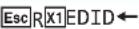 | 14 ← | Read data as text from the EDID assigned and used on input 1 . |
| View EDID native resolution | 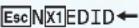 | 16 ← | Read out native resolution and refresh rate from the EDID assigned to the specified input in plain text.Example: 1920x1200 @60.00Hz |
| Request part number | 60-nnnn-nn← | See www.extron.com, for part numbers | |
| Query firmware version | X.XX← | ||
| Query firmware version w/build | X.XX.XXXX← | ||
| KEY: 1 = Input number 0 through 2 = Switch mode 0 = Ma 14 = Raw EDID date 128 or 256 by 16 = Current EDID native resolution | 2 = Auto-input switching low | 1 = Auto-input switching high | |
| Verbose mode | |||
| NOTE: If tagged responses are enabled (modes 2 and 3), all “view” commands return the prefix and the value, just as the “set” commands do.For example, the view autoswitch mode ← command returns Ausw 3 ← in verbose mode. | |||
| Set verbose mode | |||
| Read verbose mode | |||
| KEY: 17 = Verbose mode 0 = Cle 1 = Ver | 2 = Ta 1 1 = Ver | 3 = Ve 1 | 4 |
Configuration Software
This section details the Extron Product Configuration Software (PCS), available on the Extron website. The Windows-based PCS communicates with the transmitter via the rear panel Remote RS-232 port. The following topics are discussed:
• Installing the Software/Firmware
• Using PCS with the DTP T UWP 4K D Transmitters
Installing the Software/Firmware
PCS and Firmware are available on the Extron website. Download and install both programs as follows:
NOTES:
- An Extron Insider account is required to download either firmware or software.
-
Software and firmware can also be downloaded from the Download tab on the product web page.
-
Access www.extron.com and log in to your Insider Account.
- Mouse over the Download link at the top of the page (see figure 12, ①).

Figure 12. Downloading a Software or Firmware Package
- Click the appropriate link on the drop-down list.
For software, click the Software link (②). The Download Center Software page opens (see figure 13 on page 21). If the software is listed, click link (see the PCS Product Configuration Software link ③) and skip to step 5.
For firmware, click the Firmware link (4). The Download Center Firmware page opens (see figure 14 on page 21).
- Search for the name of the software or the name of the device for firmware.
For software, type the name of the software into the Search Software field and select the desired software (see figure 8).
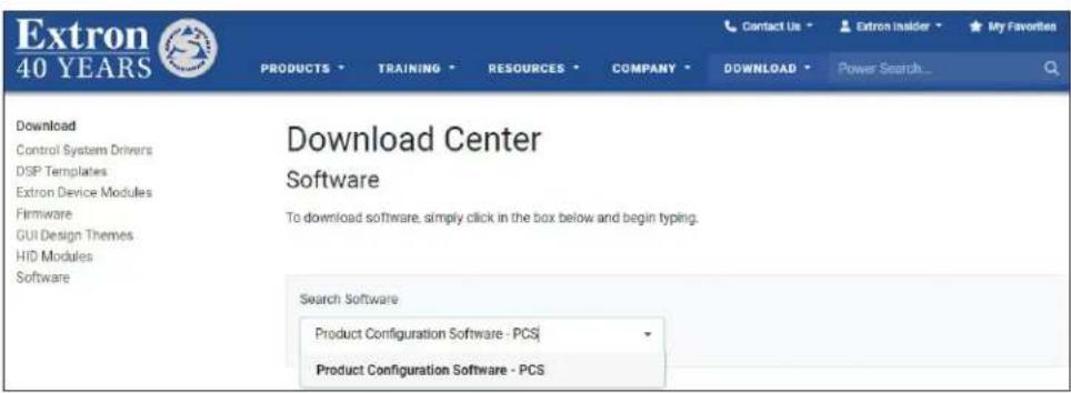
Figure 13. Software Download Center Page
The selected software page opens below the search (see figure 14).
| Version | Release Date | Release Notes |
| 4.10.2 Download Updated | Feb. 14, 2024 | Release Notes |
| Summary • Support for DA2 HD 8K L • Various bug fixes |
Figure 14. PCS Software Download
For Firmware: Type the name of the device into the Search Firmware field and select the desired device. The searched firmware page opens below the search (see figure 11).

Figure 15. Firmware Page with Search Bar
- Click Download (see figure 14 and figure 15) and follow the on-screen instructions. An executable (.exe) file is downloaded to the PC. Run this program to place the firmware on the PC for future use. Make a note of the folder where the firmware file was saved.
- (Optional) Click Release Notes for more information about the firmware update.
-
(Optional) Click Archives to download previous versions of firmware or software.
-
Install the software.
a. Navigate to the folder where the software file was downloaded.
b. Double-click the executable file and follow the on-screen directions to install the software.
For Firmware:
a. To install via PCS, select Update Firmware from the Device list in PCS.
b. To install via Firmware Loader, see Installing the Software/Firmware on page 20.
Using PCS with the DTP T UWP 4K D Transmitters
The Extron Product Configuration Software window opens with the Device Discovery panel open. Connect to the device using the Device Discovery panel or the TCP/IP panel (see figure 16 on page 22).
Device Discovery Panel
The Device Discovery panel displays accessible Extron devices connected directly to the PC via the front panel USB mini-B port. Devices are identified and sorted by model, IP address, device name, or connection method.
Start the Extron Product Configuration Software as follows:
- Click Start > Extron > Extron Product Configuration Software.
The Product Configuration Software opens to the Device Discovery screen (see figure 16).
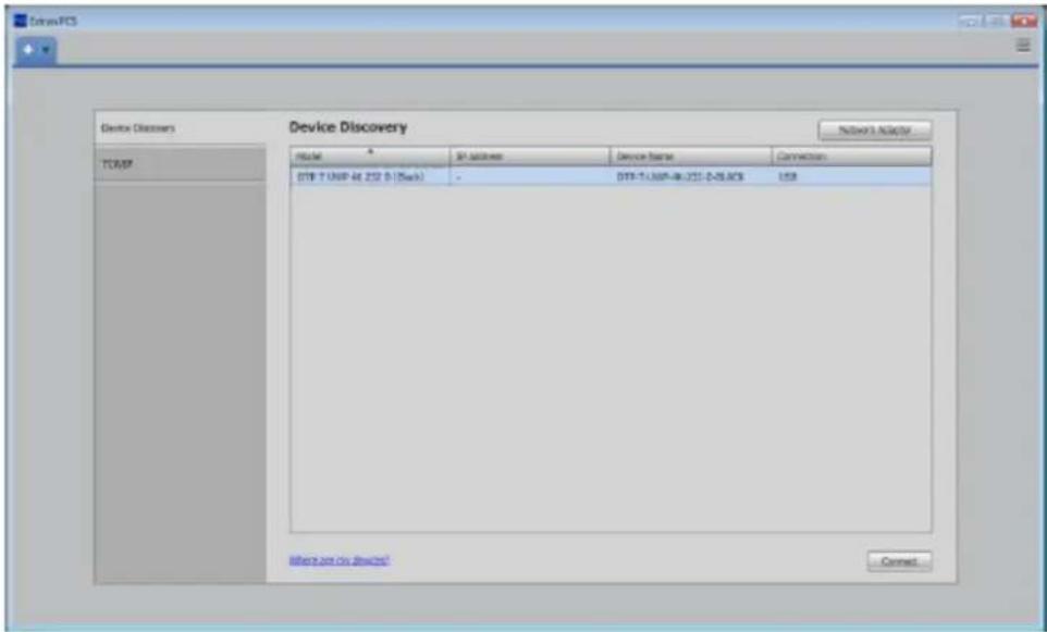
Figure 16. Device Discovery Screen
- Select the DTP T UWP 4K D3 unit by clicking on it to highlight it in the list (①).
- Click Connect ( ②). The Product Configuration Software opens to the Input/Output Configuration window (see figure 17 on page 23).

Figure 17. Product Configuration Software
AV Controls
Use the AV Controls panel to:
- Select Input
- Mute Audio
- Mute Video
- Mute Audio and Video
- Mute Sync

Figure 18. AV Controls Panel
Input/Output Configuration

Figure 19. Input/Output Configuration Screen
Input Configuration
The Input Configuration panel displays the inputs, and signal type. HDCP authorization can be enabled or disabled by selecting or deselecting the HDCP Authorized checkbox.
HDCP Authorized — Allows a user to turn off HDCP communication on the input. This is useful for devices that always encrypt their output if the downstream sink is capable of HDCP. By not allowing HDCP signals on an input, most content from these sources can be passed as a non-encrypted signal to analog and digital video outputs.
Output Configuration
• Color Bit Depth — Options include Auto (default) or Force 8-bit.
- HDCP Status — Shows the HDCP status of the display connected to the receiver.
- 5V Hot-Plug Mode — Options include Auto or Enabled (default)
- HDMI Video Pass-Through Mode — Enabling this option sets the HDMI input to pass-through a 4K30 signal unaltered. The default setting is Auto.

Figure 20. Output Configuration Panel
NOTES: When Pass-Through mode is enabled:
• Audio cannot be embedded.
• Neither audio nor video can be muted.
- If audio embedding or audio or video mute is selected in PCS, the software displays the changed settings, but the operation of the unit is unaffected.
EDID Minder

Figure 21. EDID Minder Screen
Extron EDID Minder automatically manages the EDID information between a digital display device and one or more input sources. The EDID Minder screen has options to assign EDID to an input, import non-factory default EDID into the PCS software EDID library, and save EDID from a connected DTP T UWP 4K D user-assigned memory slot. The resolution, refresh rate, and audio support of all of the EDID located locally in the PCS EDID library can also be viewed.
EDID Minder panels
- Filter — Displays various filters that can be enabled to easily locate specific EDID.
- Favorites — Displays commonly used EDID which can be added to the panel for quick access.
- Connected Outputs — Displays the EDID of output (color-coded green) that has been connected to the Loop-Thru port of the DTP T UWP 4K D unit.
• Available EDID — Displays the library of available EDID located on the connected unit or the local PC. - Inputs — Displays the current EDID of the connected input.
Image Settings
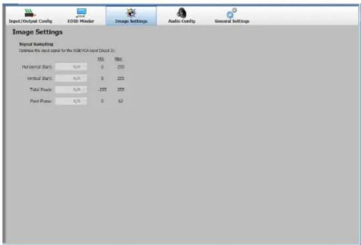
NOTE: The image settings on this panel only apply to the RGB/VGA input (Input 2).
Adjust the following settings by either typing the desired values into their respective fields, or using the up and down arrows next to each field.
- Horizontal Start
- Vertical Start
- Total Pixels
- Pixel Phase
Figure 22. Image Settings Screen
Audio Configuration

Figure 23. Image Settings Screen
These settings configure the audio for the inputs on the transmitter. The Audio Format options include:
| HDMI Input VGA Input | |
| Auto (Embedded digital audio takes priority) No Embedding | |
| Digital Audio Embedded Audio | |
| Analog Audio | |
General Settings
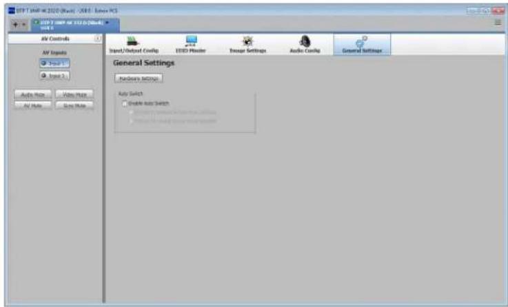
Figure 24. General Settings Screen
The General Settings screen has Auto Switch settings and a button to access the Hardware Settings window.
Auto Switch — Click the check box to enable auto switch and choose the Auto Switch priority by clicking the desired the radio button.
Hardware Settings

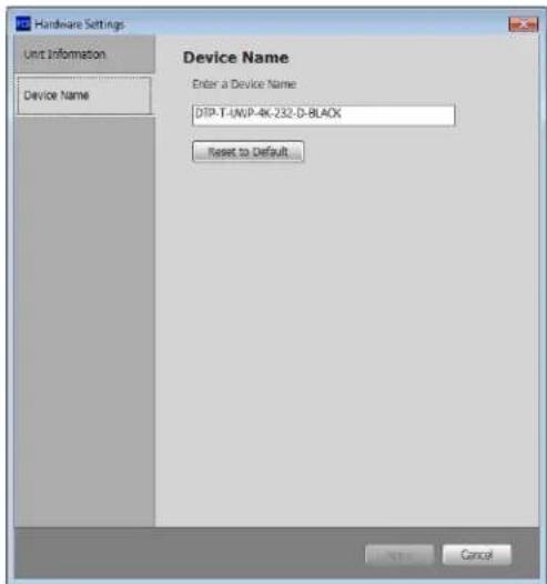
Figure 25. Hardware Settings Window Figure 26. Device Name Window
The Unit Information tab (see figure 25) of the Hardware Settings window is read-only with information regarding the connected DTP T UWP 4K D unit.
The Device Name tab (see figure 26) of the Hardware Settings window allows the user to change the device name, if necessary.
Device List
The Device list has options for device connection, configuration, and information (see figure 27).
- Disconnect — Disconnect the device from the PCS program and close the Device tab.
- Settings — Open the Hardware Settings submenu with the following options:
- Hardware Settings — Displays the dialog box with device information and a side tab to change the device name.
- Reset Device — Open the Reset Device... dialog box, with selectable modes for resetting the connected device, as well as the Unit Information (also displayed in the Hardware Settings dialog box).
- Update Firmware — Open the Update Firmware to this Device... submenu to upload firmware from the host device to the connected device.
NOTE: If necessary, download new firmware from the Extron website (see Installing the Software/Firmware on page 20).
- About This Module — Open the About This Module dialog box, with the module part number and firmware version of the connected device.

Figure 27. Device List
Software List
The Software list (see figure 28) has options pertaining to PCS settings.

Figure 28. Software List
Show Expanded Device Tabs
Selecting Show Expanded Device Tabs from the Software menu displays the device IP address or connection method in the Device tab.

Figure 29. Expanded Device Tab
Software Settings
This option resets all disabled confirmation dialogs to the default settings.
- From the Software list, select Software Settings. The Software Settings dialog box opens (see figure 30).

Figure 30. Software Settings Dialog Box
- Click the Re-enable Confirmation Dialogs button (①). The dialog box closes and the reset is complete. Alternatively, click the Close button (②) to close the dialog box without re-enabling the confirmation dialogs.
Tutorial
Display a general overview of where to find features in the PCS framework.
- From the Software list, select Tutorial. The Tutorial dialog box opens.
- Click the I Get It! button to close the dialog box.
Extron PCS Help
Open the PCS help file for general PCS operations.
From the Software list, select Extron PCS Help.
Application Licensing
Log into PCS with your Extron Insider account or check licensing details.

Figure 31. Application Licensing Dialog Box
About Extron PCS
Display information about the current PCS version.
- From the Software list, select About Extron PCS. The About - Extron PCS dialog box opens.

Figure 32. About - Extron PCS Dialog Box
- Click the Details button (see figure 32, ①) for more information.
- To display details about third-party software packages and associated licensing, click Licenses (2).
- Click the OK button (③) to close the dialog box.
Exit
Disconnect connected devices and close the application.
- From the Software list, select Exit. If device tabs are open, the Exit dialog box opens (see figure 33).
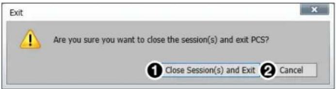
Figure 33. Exit Dialog Box
- Click the Close Session(s) and Exit button (①) to disconnect the software from connected devices, close all offline device tabs, and close the software.
Alternatively, click the Cancel button (②) to leave the software open.
Updating the Firmware
Firmware can be updated via Product Configuration Software.
Update the unit firmware as follows:
- Download the current firmware to a PC connected to the DTP T USW 233 from the Extron website (see Installing the Software/Firmware on page 21).
- Open PCS and connect to the DTP T UWP 4K D device (see Device Discovery Panel on page 22).
- From the drop-down Device list, select Update Firmware > Update Firmware to this Device... The Update Firmware dialog box opens, stating that the software must disconnect from the device to update firmware.
- Click Continue. The Update Firmware to this Device dialog box opens.
- Click the Open Firmware File... button, browse to, and select the desired firmware file.
ATTENTION:
This section provides information about updating the firmware of the DTP T UWP 4K D series and product wallplate dimensions.
Decorator-Style Wallplate Template Dimensions
To create a template, use the dimensions shown in figure 34.
NOTES:
• The drawing is not full size or to scale. DO NOT scale up or print to use as a template.
• Full size templates are available at www.extron.com.
Template for the 2-gang mounting bracket

Figure 34. Decorator-Style Wallplate Template Dimensions
Best Practices for Cleaning Your Extron Products
There may be times when it becomes necessary to clean your Extron product. Plastic surfaces and cosmetic finishes can be damaged by long term exposure to chemicals. Therefore, Extron recommends the following guidelines when cleaning our products.
All Extron products can be safely cleaned with:
- 70% concentration or higher Isopropyl Alcohol
-
Disinfectant cleaners that:
-
Are non-ammonium based (for example, contains no ammonium chloride)
- Contain 2% or less sodium hypochlorite (for example, 2% bleach, 98% water)
It is important to follow these general guidelines when cleaning:
- If possible, unplug the device.
- Spray the cleaner on a lint-free cloth until the cloth is damp.
- Do not spray the cleaner directly onto the product.
- Gently clean the product surface using the cloth.
Your health and safety are our top priority. Keeping devices clean, especially those in high-traffic environments and high-use applications, is a crucial step in minimizing the spread of infections. Please contact us if you have any questions about the guidelines or if you have a question about cleaning the product.

Extron Warranty

This Limited Warranty does not apply if the fault has been caused by misuse, improper handling care, electrical or mechanical abuse, abnormal operating conditions or non-Extron authorized modification to the product. Extron Electronics makes no further warranties either expressed or
implied with respect to the product and its quality, performance, merchantability, or fitness for any particular use. In no event will Extron Electronics be liable for direct, indirect, or consequential damages resulting from any defect in this product even if Extron Electronics has been advised of such damage. Please note that laws vary from state to state and country to country, and that some provisions of this warranty may not apply to you.
Powered Warranty
Extron warrants its powered products against defects in materials and workmanship for a period of three years from the date of invoice. In the event of malfunction during the warranty period, Extron will repair or replace a product to whatever extent it shall deem necessary to restore the product to proper operating condition.
Powered Warranty Exception
Everlast™ Power Supplies — Extron warrants Everlast power supplies against any defects in materials and workmanship for a period of seven years from the date of invoice. In the event of a malfunction during the warranty period, Extron will repair or replace the power supply to its original operating condition. Extron engineers will examine the returned product and determine whether the Everlast Power Supply Warranty or Powered Product Warranty applies.
Speakers — Extron warrants Flat Field®, SoundField®, SpeedMount®, Column Array, and System INTEGRATOR® speakers against any defects in materials and workmanship for a period of five years from the date of invoice.
Touchscreens — Extron warrants touchscreen display and overlay components against any defects in materials and workmanship for a period of one year from the date of invoice.
Annotator 300 — Extron warrants the Annotator 300 against any defects in materials and workmanship for a period of five years from the date of invoice.
Non-Powered Warranty Exception
Cable Cubby, Hideaway Surface Access Enclosures and Retractors — Extron warrants Cable Cubby cable access enclosures, HSA Hideaway Surface Access enclosures, and Retractor cable retraction modules for a period of three years from the date of invoice.
Active Cables and Active Adapters — Extron warrants active cables and active adapter cables for a period of three years from the date of invoice.
Cable Termination Tools and Dies — Extron warrants cable termination tools for a period of three years from the date of invoice, excluding the die.
Return Information
Units must be returned insured, with shipping charges prepaid. If not insured, you assume the risk of loss or damage during shipment. Returned units must include the serial number and a description of the problem, as well as the name of the person to contact in case there are any questions.
NOTE: To assure the highest level of service, a return authorization number must be obtained from Extron before products are returned for service. Products must be shipped to Extron, prepaid along with proof of purchase only after obtaining a Return Authorization (RA) number from the Extron Customer Support department.
Please contact Extron to receive an RA (Return Authorization) number:
USA: 714.491.1500 or 800.633.9876
Asia: 65.6383.4400
Europe: 31.33.453.4040 or 800.3987.6673
Japan: 81.3.3511.7655
Africa and Middle East:
971.4.299.1800

- DTP T UWP 4K D SERIES
- USER GUIDE HDMI TRANSMITTERS
- SAFETY INSTRUCTIONS
- SAFETY INSTRUCTIONS • ENGLISH
- FCC CLASS A NOTICE
- CONVENTIONS USED IN THIS GUIDE
- NOTIFICATIONS
- SOFTWARE COMMANDS
- SPECIFICATIONS AVAILABILITY
- EXTRON GLOSSARY OF TERMS
- CONTENTS
- INTRODUCTION....1
- INSTALLATION AND OPERATION 4
- SIS COMMAND CONTROL 14
- CONFIGURATION SOFTWARE.... 20
- REFERENCE INFORMATION 31
- EXTRON WARRANTY.... 33
- INTRODUCTION
- ABOUT THIS GUIDE
- TERMS USED IN THIS GUIDE
- ABOUT THE AND DTP T UWP 4K D EXTENDERS
- TWISTED PAIR CABLE ADVANTAGES
- CONTROL COMMUNICATIONS
- TRANSMISSION DISTANCE
- FEATURES
- INSTALLATION AND OPERATION
- MOUNTING THE TRANSMITTER
- ATTENTION
- UL AND SAFETY GUIDELINES
- CAUTION
- SITE PREPARATION AND WALL BOX INSTALLATION
- NOTES
- MUD RING INSTALLATION
- FINAL INSTALLATION
- DTP T UWP 4K D CONNECTIONS
- REAR PANEL
- TWISTED PAIR RECOMMENDATIONS FOR DTP COMMUNICATION
- SUPPORTED CABLES
- CABLE RECOMMENDATIONS
- POWER SUPPLY WIRING
- REMOTE RS-232 AND CONTACT CLOSURE CONNECTOR
- OVER DTP RS-232 CONNECTOR
- OPERATION
- TRANSMITTER LEDS
- SYSTEM OPERATION
- AUDIO CONFIGURATION
- EDID MINDER
- SIS COMMAND CONTROL
- CONTACT CLOSURE CONTROL
- SIMPLE INSTRUCTION SET CONTROL
- HOST-TO-EXTENDER COMMUNICATIONS
- EXTENDER-INITIATED MESSAGES
- ERROR RESPONSES
- TIMEOUT
- USING THE COMMAND AND RESPONSE TABLE
- SYMBOL DEFINITIONS
- COMMAND AND RESPONSE TABLE FOR SIS COMMANDS
- CONFIGURATION SOFTWARE
- INSTALLING THE SOFTWARE/FIRMWARE
- FOR FIRMWARE
- USING PCS WITH THE DTP T UWP 4K D TRANSMITTERS
- DEVICE DISCOVERY PANEL
- AV CONTROLS
- INPUT/OUTPUT CONFIGURATION
- INPUT CONFIGURATION
- OUTPUT CONFIGURATION
- EDID MINDER PANELS
- IMAGE SETTINGS
- GENERAL SETTINGS
- HARDWARE SETTINGS
- DEVICE LIST
- SOFTWARE LIST
- SOFTWARE SETTINGS
- TUTORIAL
- EXTRON PCS HELP
- APPLICATION LICENSING
- ABOUT EXTRON PCS
- EXIT
- UPDATING THE FIRMWARE
- UPDATE THE UNIT FIRMWARE AS FOLLOWS
- DECORATOR-STYLE WALLPLATE TEMPLATE DIMENSIONS
- BEST PRACTICES FOR CLEANING YOUR EXTRON PRODUCTS
- EXTRON WARRANTY
- POWERED WARRANTY
- POWERED WARRANTY EXCEPTION
- NON-POWERED WARRANTY EXCEPTION
- RETURN INFORMATION
Brand : Extron
Model : DTP T UWP 4K 232 D
Category : HDMI Transmitter