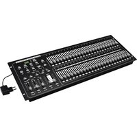
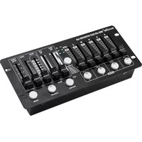
DMX Scene Setter 24/48 - Controller Eurolite - Free user manual and instructions
Find the device manual for free DMX Scene Setter 24/48 Eurolite in PDF.


| Product Type | DMX Controller |
| Model | DMX Scene Setter 24/48 |
| Brand | Eurolite |
| DMX Channels | 24 channels (48 scenes) |
| Power Supply | 9V DC, 500 mA (typical) |
| Dimensions | 483 x 44 x 150 mm (19" rack mount) |
| Weight | Approx. 2.0 kg |
| Chase Sequences | Up to 10 programmable chases |
| Scene Storage | 48 scenes (2 banks of 24) |
| DMX Output | 1 x 3-pin XLR male |
| DMX Input | 1 x 3-pin XLR female (for linking) |
| Display | 2-line LCD with backlight |
| Faders | 24 channel faders (60mm) |
| Scene Master | Master fader for overall intensity |
| Blackout Button | Instant blackout function |
| Maintenance | Clean with soft, dry cloth; keep away from moisture |
| Safety | Use only supplied power adapter; avoid exposure to rain or dust |
| Spare Parts | Contact Eurolite for spare faders or power supply |
| Repairability | Service by qualified personnel only |
| General Information | Ideal for small to medium lighting setups in theaters, clubs, and events |
Frequently Asked Questions - DMX Scene Setter 24/48 Eurolite
User questions about DMX Scene Setter 24/48 Eurolite
0 question about this device. Answer the ones you know or ask your own.
Ask a new question about this device
Download the instructions for your Controller in PDF format for free! Find your manual DMX Scene Setter 24/48 - Eurolite and take your electronic device back in hand. On this page are published all the documents necessary for the use of your device. DMX Scene Setter 24/48 by Eurolite.
USER MANUAL DMX Scene Setter 24/48 Eurolite
DMX SCENE SETTER 24/48
www.eurolite.de

www.youtube.com/eurolitevideo

www.facebook.com/Eurolitefans
DMX512 connection 24
Connection to the mains.... 24
Sound control 24
Foot pedal 24
OPERATING MODES 25
CHASE/SCENES 25
DOUBLE PRESET 25
1-48 SINGLE PRESET 25
PROGRAMMING 25
Enable program mode 25
Security for your programs 25
Program scenes 26
Enable edit mode 26
Erase a program 26
Erase all programs.... 26
Clear a scene or scenes 27
Delete a step or steps 27
Insert a step or steps 27
Modify a step or steps 28
RUNNING PROGRAMS 28
Running chase programs 28
Sound control 28
Running a program with a standard speed 28
Deleting a memorized standard speed 29
Changing the speed mode from 5 to 10 minutes... 29
GENERAL FUNCTIONS 29
Reverse the direction of chase programs .... 29
Fade time 29
TAP SYNC button 29
Master fader 29
Single mode 29
Mix mode 30
Dimmer display 30
Blind and Home 30
Add and Kill 30
MIDI SETTINGS 30
Setting MIDI IN 30
Setting MIDI OUT 30
Exit MIDI setting 30
Receiving MIDI file dump 30
Sending MIDI file dump 31
Implementation 31
CLEANING AND MAINTENANCE 31
TECHNICAL SPECIFICATIONS 31
Accessories.... 31
D00108796, version 3.0, publ. 25/02/2019
For product updates, documentation, software and support please visit www.eurolite.de. You can find the latest version of this user manual in the product's download section.
© 2019 Eurolite. All rights reserved.
No part of this document may be reproduced in any form without the written permission of the copyright owner. The contents of this document are subject to revision without notice due to continued progress in methodology, design, and manufacturing. Eurolite shall have no liability for any error or damage of any kind resulting from the use of this document.
All trademarks mentioned herein are the property of their respective owners.
INTRODUCTION
Experience Eurolite.
Product videos, suitable accessories, firmware and software updates, documentation and the latest news about the brand. You will find this and much more on our website. You are also welcome to visit our YouTube channel and find us on Facebook.

www.eurolite.de

www.youtube.com/eurolitevideo

www.facebook.com/Eurolitefans
Welcome to Eurolite! Thank you for choosing one of our products. Eurolite is your connection to the world of show with an unparalleled variety of products, both for professionals and beginners.
If you follow the instructions given in this manual, we are sure that you will enjoy this product for a long period of time. This user manual will show you how to install, set up and operate your new Eurolite product.
Users of this product are recommended to carefully read all warnings in order to protect yourself and others from damage. Please keep this manual for future needs and pass it on to further owners.
Product features
• Comfortable DMX controller
• 48 control channels
• 96 memorizable programs via 4 pages
• 24 scenes can be called up directly via the faders
- Blackout function
• Mix and single chase function
- Blind/home function
• Sound control via built-in microphone or via line input
• Supports standard MIDI
• 3-pin XLR connector with polarity selector
- Footswitch control possible
- Desktop console
- Rack installation (27") with 6 units

IMPORTANT SAFETY INSTRUCTIONS
CAUTION!

Operating conditions
This device has been designed for indoor use only. Keep this device away from rain and moisture.
DANGER!

Electric shock caused by short-circuit
Be careful with your operations. With a dangerous voltage you can suffer a dangerous electric shock when touching the wires!
- Please read these operating instructions carefully before using the product. They contain important information for the correct use of your product. Please keep them for future reference.
- Only use the product according to the instructions given herein. Damages due to failure to follow these operating instructions will void the warranty! We do not assume any liability for any resulting damage.
- We do not assume any liability for material and personal damage caused by improper use or non-compliance with the safety instructions. In such cases, the warranty/guarantee will be null and void.
- Unauthorized rebuilds or modifications of the product are not permitted for reasons of safety and render the warranty invalid.
- Never open any part of the product to prevent a possible electric shock.
- IMPORTANT: This product is not an outdoor product! Only for indoor use! Do not use this device near water. The recommended temperature range is -5 to +45 °C.
- To clean the unit, disconnect it from the power source.
- Only use a soft cloth, never use any solvent.
- Do not touch the power cord and connectors with wet hands as it may cause electric shock.
- This product is not a toy. Keep it out of the reach of children and pets. Do not leave packaging material lying around carelessly.
- This unit corresponds to all required directives of the EU and is therefore marked with .
Intended use
- The DMX controller serves for operation of DMX-controlled light effect devices such as LED spot lights, moving heads and scanners.
- This device is designed for professional use in the field of event technology, e.g. on stage.
Disposal of old equipment

When to be definitively put out of operation, take the product to a local recycling plant for a disposal which is not harmful to the environment. Devices marked with this symbol must not be disposed of as household waste. Contact your retailer or local authorities for more information. Remove any inserted batteries and dispose of them separately from the product.


You as the end user are required by law (Battery Ordinance) to return all used batteries/rechargeable batteries. Disposing of them in the household waste is prohibited. You may return your used batteries free of charge to collection points in your municipality and anywhere where batteries/rechargeable batteries are sold. By disposing of used devices and batteries correctly, you contribute to the protection of the environment.
OPERATING ELEMENTS AND CONNECTIONS


| No. | Element Function | |
| 1 | PRESET A indicators Show the current intensity of the channels 1-24. | |
| 2 | Channel faders 1-24 For adjusting the DMX values of channels 1-24 for the connected DMX fixtures. | |
| 3 | Flash buttons 1-24 These 24 buttons are used to bring an individual channel (1-24) to full intensity (255). | |
| 4 | PRESET B indicators Show the current intensity of the channels 25-48. | |
| 5 | SCENE indicators Light up when corresponding scenes are active. | |
| 6 | Channel faders 25-48 For adjusting the DMX values of channels 25-48 for the connected DMX fixtures. | |
| 7 | Flash buttons 25-48 These 24 buttons are used to bring an individual channel (25-48) to full intensity (255). | |
| 8 | BLIND button This function takes the channel out of the program in CHASE/SCENE mode. | |
| 9 | HOME button This button is used to deactivate the Blind function. | |
| 10 | TAP SYNC button | Press this button twice to adjust the running speed of the chase program. |
| 11 | FULL ON button | When activated, all channel outputs will be set to maximum (255) and blackout mode is disabled. This button is ideal for testing if a DMX signal is fed to the DMX fixtures. |
| 12 | BLACK OUT button | Sets all control channels to the value zero regardless of the FULL ON button. The corresponding LED is flashing. Thus, it is possible to blackout e. g. all DMX fixtures. As a basic setting, the Blackout function is activated when switching on. |
| 13 | MASTER A fader | This fader controls overall output of channels 1-24 (Preset A). |
| 14 | MASTER B fader | This fader controls the scenes/chases in Chase/Scene and Single Preset mode, and the overall output of channels 25-48 (Preset B) in Double Preset mode. |
| 15 | FADE fader | To adjust the fade time between the individual steps of a chase. |
| 16 | SPEED fader | To adjust the chase speed.Note: Both the TAP SYNC button and the SPEED fader can be used to set the chase speed. The last input is valid. |
| 17 | AUDIO LEVEL fader | This fader controls the sensitivity of the built-in microphone or of the audio signal that is fed into the AUDIO input. |
| 18 | MASTER A button | Not available. |
| 19 | PARK button | Used to switch between SINGLE CHASE mode and MIX CHASE mode when the CHASE/SCENES operating mode is selected.SINGLE CHASE: All chase programs will run in sequential order.MIX CHASE: All chase programs will run synchronously. In the event that DMX values contradict each other, the higher value is valid. |
| 20 | HOLD button | Press and hold down this button to hold all adjusted output values. Thus, it is possible to maintain a current scene. |
| 21 | STEP button | This button is used to go to next step when the Speed Fader is pushed to the bottom or in Edit mode. |
| 22 | AUDIO button | This button activates sound control mode. |
| 23 | DARK button | Press and hold down this button to set all control channels to the value zero regardless of the FULL ON button. |
| 24 | MODE SELECT button | Selects the operating mode: Chase/Scene mode, Double Preset or Single Preset. |
| 25 | PAGE/REC CLEAR button | To switch the flash buttons between the four pages. The LEDs above the button indicate which page is selected.Press this button and the RECORD button to clear the internal memory. |
| 26 | REC EXIT/ADD KILL button | Press this button and the RECORD button to exit from Program or Edit mode.In Add mode, multiple scenes or flash buttons will be on at a time. Press this button to select Kill mode. Then pressing any flash button will kill any other scenes or programs. |
| 27 | RECORD/SHIFT button | To enable Program mode hold down this button and tap the FLASH buttons 1, 6, 6 and 8 in sequence.Shortly press this button to memorize a step in Program mode.Press this button and a flash button (25-48) to memorize a chase program.The Shift function is used in with other buttons. |
| 28 | DOWN/BEAT REV button | The DOWN function allows to modify a scene in Edit mode.BEAT REV inverts the running direction of all the programs with memorized standard speed. |
| 29 | UP/CHASE REV button | The UP function allows to modify a scene in Edit mode.CHASE REV inverts the direction of all programs currently running. |
| 30 | DELETE/REV ONE button | DELETE is used to delete a step of a scene.REV ONE inverts the running direction of particular program. For this, press and hold down this button, then press down the FLASH button corresponding to your desired program and release together. |
| 31 | INSERT/0% OR 0-255 button | INSERT is used to add one or multiple steps to a scene.Press this button and the SHIFT button to select the mode of indication (0% or 0-255) in the display. |
| 32 | EDIT/ALL REV button | EDIT is used to active Edit mode.ALL REV inverts the running direction of all programs. |
| 33 | Display with indicators | Shows the current activity or programming state. |
| 34 | Power on/off | Switches the controller on and off. |
| 35 | Power input | Connect the power adapter provided here. |
| 36 | MIDI THRU/OUT/ IN jacks | To interconnect two Scene Setters for data exchange or to connect a sequencer or another MIDI device. |
| 37 | DMX512 output | 3-pin XLR jack for connecting the DMX input of the first DMX fixture. |
| 38 | Polarity switch | To adjust the polarity of the DMX output.left position: PIN 2 = Data -, Pin 3 Data +right position: PIN 2 = Data +, Pin 3 Data -Prior to connecting light effect units, adjust the polarity with the sliding switch. Set the switch to the left position for EUROLITE devices. |
| 39 | Line input | RCA jack for connecting an audio unit with line output (e.g. CD player, mixer) to control the run of a chase to the rhythm of the music; when connecting the jack the internal microphone is switched off. |
| 40 | REMOTE jack | 6.3 mm jack for connecting a footswitch. |
SETUP
Installation
Install the unit on a plane surface or in your rack. When choosing the installation spot make sure that there is enough space around the unit for ventilation or that heated air from the rack can be passed on to improve heat radiation. Steady overheating will damage the unit. Matching items are available as accessory, e.g. 30111556 Mixer case Pro MCB-27.
DMX512 connection
Use a DMX cable and 3-pin XLR plugs and connectors in order to connect the foot switch to the DMX chain. If you wish to connect fixtures with other XLR outputs, you need to use adapter cables.
1 Connect the DMX output of the controller to the DMX input of the first light effect unit.
2 Connect the DMX output of the first fixture in the DMX chain to the DMX input of the next fixture. Always connect one output to the input of the next fixture until all fixtures are connected.
3 At the last fixture, the DMX cable has to be terminated with a terminator. For this solder a 120 Ω resistor between signal (−) and signal (+) into a 3-pin XLR plug and plug it in the DMX output of the last fixture.
4 If the cable length exceeds 300 m or the number of DMX devices is greater than 32, it is recommended to insert a DMX level amplifier to ensure proper data transmission.
Pin connection:
DMX-output
XLR mounting-socket:

DMX-input
XLR mounting-plug:

1: Ground
2: Signal (-)
3: Signal (+)
Connection to the mains
Connect the power adapter provided to the corresponding input on the foot switch and to a mains socket. After the operation, disconnect the mains plug unit from the socket, to prevent unnecessary power consumption.
Sound control
For sound-controlled run of a chase it is possible to connect an audio unit with line output (e.g. CD player, mixer) to the jack AUDIO (sensitivity 0.1-1 V). When connecting the audio unit to the jack, the internal microphone is switched off.
Foot pedal
For convenient control of the functions full on and blackout, a foot pedal (e.g. item 70064490 EUROLITE Foot Controller) can be connected to the 6.3 mm jack REMOTE.
OPERATING MODES
The Scene Setter offers three operating modes which can be selected via the MODE SELECT button. The LEDs below the button indicate which mode is selected.
CHASE/SCENES
1 This mode will give you control of the DMX channels via the upper 24 channel faders. The lower 24 channels faders will give you access to your memorized chase programs.
2 The master faders are in reverse position, i.e. Master A is at is at its maximum when positioned all the way up, while Master B is at its maximum when positioned all the way down.
DOUBLE PRESET
1 This mode allows for a special working method often used in smaller theaters. Both fader rows have an identical function.
2 Both, the upper channel faders 1-24, and the lower channel faders 25-48 control DMX channels 1-24.
3 Master fader A controls channel faders 1-24, and master fader B channel faders 25-48.
4 Example: If both master faders are moved up, they will output the DMX values of the upper channel faders 1-24. Meanwhile, you can adjust the next scene with the lower channel faders 25-48. If you move both master faders down, the controller will fade from the upper setting to the lower setting. Then you can prepare the next scene and fade from the lower setting to the upper setting, etc.
5 This mode cannot be used for programming.
1-48 SINGLE PRESET
This mode will give you control of all 48 DMX channels. Use this mode during a show or in Program mode.
PROGRAMMING
Enable program mode
1 Press and hold down the RECORD button.
2 While holding down the RECORD button, tap the FLASH buttons 1, 6, 6 and 8 in sequence.
3 Release the RECORD button, the RECORD LED lights up, now you can begin programming your chase patterns.
NOTE
The first time you turn on your unit, the default setting of the Record Code is Flash buttons 1, 6, 6 and 8. You may change the Record Code to protect your programs.
IMPORTANT
Always remember to exit Program mode when you won't continue your programming, otherwise you may lose control of your unit.
Security for your programs
To protect your programs from any editing by others, you may change the Record Code.
1 Enter current Record Code (FLASH buttons 1, 6, 6 and 8).
2 Press and hold down the RECORD and EDIT buttons at a time.
3 While holding the RECORD and EDIT buttons, tap the desired FLASH button to enter a new Record Code. The Record Code consists of 4 flash buttons (the same button or different buttons), be sure your new Record Code consists of 4 flash buttons.
4 Enter your new Record Code a second time, all channel LEDs and scene LEDs will flash three times; now the Record Code is changed.
5 Exit Program mode. Tap the REC EXIT button while pressing and holding down the RECORD button, release the two buttons at a time, the Program mode is disengaged.
NOTES
1 The second time you enter your new Record Code different from that of the first time, the LEDs will not flash, which means you've failed to change the Record Code.
2 When you enter a new Record Code the first time, provided that you want to cancel the new Record Code, press and hold down the RECORD and REC EXIT buttons at a time to exit.
Program scenes
1 Enable Program mode.
2 Select the 1-48 SINGLE mode by tapping the MODE SELECT button. This will give you control of all 48 channels as you program. Be sure that MASTER A and B faders are both set to maximum (Master A is at its maximum when positioned all the way up, while Master B is at its maximum when positioned all the way down).
3 Create a desired scene using Channel Faders 1-48. At 0% or DMX 255, these faders should be at 10 position.
4 Once the scene is satisfactory, tap the RECORD button to program the scene as a step into the memory.
5 Repeat step 3 and 4 until all desired steps have been programmed into memory.
6 Select a chase bank to store your program. Tap the PAGE button select a page (page 1-4) to store your scenes.
7 Press a FLASH button between 25-48 while holding down the RECORD button. All LEDs will flash indicating the scenes have been programmed into memory.
8 If you are not satisfied with the scene or scenes, you may tap the REC CLEAR button while pressing and holding the RECORD button. All LEDs will flash, indicating the scenes have been cleared.
9 You can continue programming or exit. To exit Program
EXAMPLE
Program a 16-step chase with channel 1-32 at full in sequence and assign into Flash button 25 of Page 1.
1 Enable Program mode.
2 Push the MASTER A and B faders to maximum position and the FADE fader to top.
3 Tap the MODE SELECT button to select 1-48 SINGLE mode.
4 Push Channel fader 1 to the top position, its LED lights at full intensity.
5 Tap the RECORD button to program this step into memory.
6 Repeat steps 4 and 5 until you've programmed Channel faders 1-32.
7 Tap the RECORD button causing page 1 LED to light.
8 Tap the FLASH button 25 while holding down the RECORD button, all LEDs will flash indicating you've programmed the chase into memory.
Enable edit mode
1 Enable Program mode.
2 Use the PAGE button to select the page the program you wish to edit is on.
3 Tap the MODE SELECT button to select CHASE/SCENES mode.
4 Press and hold down the EDIT button.
5 While holding down the EDIT button, tap the FLASH button that corresponds to program you wish to edit.
6 Release the FLASH button, the relevant scene LED should light indicating you are in the Edit mode.
Erase a program
1 Enable Program mode.
2 Use the PAGE button to select the page that the program you wish to erase is on.
3 While holding down the RECORD button, tap the FLASH button (25-48) twice. Release the two buttons. All LEDs flash, indicating the program is erased.
Erase all programs
1 Press and hold the RECORD button.
2 Tap the FLASH buttons 1, 4, 2 and 3 in sequence while holding the RECORD button. All LEDs will flash, indicating all programs stored in memory have been erased.
Clear a scene or scenes
1 Enable Program mode.
2 Record a scene or scenes.
3 If you are not satisfied with the scene or scenes, you may tap the REC CLEAR button while pressing and holding the RECORD button. All LEDs will flash, indicating the scenes have been cleared.
Delete a step or steps
1 Enable Program mode.
2 Tap the STEP button to scroll to the step you wish to delete.
3 Tap the DELETE button when you reach the step you wish to delete. All LEDs will flash briefly indicating the deletion of the step.
4 Continue steps 2 and 3 until all the unwanted steps have been deleted.
5 Tap the REC EXIT button while pressing and holding down the RECORD button. The scene LED goes out, indicating the exit of Edit mode.
EXAMPLE
Delete the 3rd step of the program on Flash button 25 on Page 2.
1 Enable Program mode.
2 Tap the MODE SELECT button to select CHASE/SCENES mode.
3 Tap the PAGE button until Page 2 LED lights.
4 Tap the FLASH button 25 while pressing and down the EDIT button. The scene LED lights.
5 Tap the STEP button to scroll to the third step.
6 Tap the DELETE button to delete the step.
7 Tap the REC EXIT button while pressing and holding down the RECORD button to exit Edit mode.
Insert a step or steps
1 Record a scene or scenes you wish to insert.
2 Be sure you're in CHASE/SCENES mode. Then enter the Edit mode.
3 Tap the STEP button to scroll to the step which you wish to insert before. You may read the step from the display.
4 Tap the INSERT button to insert the step you've created. All LEDs will flash, indicating the step is inserted.
5 Tap the REC EXIT button while pressing and holding down the RECORD button. The scene LED goes out, indicating the exit of Edit mode.
EXAMPLE
Insert a step with channels 1-12 fully on at a time between step 4 and 5 of program 35.
1 Enable Program mode.
2 Push Channel faders 1-12 to the top and record the scene as a step.
3 Tap the MODE SELECT button to select CHASE/SCENES mode.
4 Tap the PAGE button until Page 2 LED lights.
5 Tap the FLASH button 35 while holding down the EDIT button, the corresponding scene LED lights.
6 Tap the STEP button to scroll to the step 4.
7 Tap the INSERT button to insert the scene you've created before.
Modify a step or steps
1 Enter Edit mode.
2 Tap the STEP button to scroll to the step you wish to modify.
3 Press and hold the UP button if you want to raise the intensity. If you want to lower the intensity, press and hold down the DOWN button.
4 While holding down the UP or DOWN button, tap the FLASH button corresponding to the DMX channel of the scene you wish to modify until you reach the desired intensity value read from the display. Then you may tap the FLASH buttons until you are satisfied with the new scene.
5 Repeat steps 2, 3 and 4 until all the steps have been modified.
6 Exit Edit mode. Tap the REC EXIT button while pressing and holding down the RECORD button. The scene LED goes out, indicating the exit of Edit mode.
RUNNING PROGRAMS
Running chase programs
1 Tap the MODE SELECT button to select CHASE/SCENES mode indicated by the red LED.
2 Tap the PAGE button to select the correct page the program you wish to run is located.
3 Push Master Fader B to its maximum position (fully down).
4 Move the desired Channel fader (25-48) to its maximum position to trigger the program, and the program will fade in depending upon current fade time.
5 You may also hold down the respective FLASH button to trigger the program.
6 Move the Channel fader to adjust the output of the current program.
7 Multiple programs can be selected at a time. Simply move multiple channel faders or hold down the respective FLASH buttons to trigger the desired programs.
8 Use the PARK button to switch between SINGLE CHASE mode and MIX CHASE mode.
- SINGLE CHASE LED lights: All chase programs will run in sequential order.
- MIX CHASE LED lights: All chase programs will run synchronously.
Sound control
1 Use the built-in microphone or plug an audio source into the RCA audio jack.
2 Select your program as described above.
3 Tap the AUDIO button until its LED lights, indicating Sound control mode is active.
4 Use the AUDIO LEVEL fader to adjust the music sensitivity.
5 To return to normal mode, tap the AUDIO button a second time causing its LED to go out. The Sound control mode is disengaged.
Running a program with a standard speed
You can define and memorize a standard speed for every chase program.
1 Be sure the Sound control mode is disengaged. Tap the MODE SELECT button to select CHASE/SCENES mode.
2 Tap the PARK button to select MIX CHASE mode. The LED lights indicating this selection.
3 Select your program as described above.
4 Move the SPEED fader until the display reads your desired value. You may also tap the TAP SYNC button twice to define your speed.
5 While pressing and holding down the REC SPEED button, tap the FLASH button (25-48) that stores the program.
6 The program will then run with the set speed when engaged.
7 Repeat steps 4 and 5 to set a new speed.
NOTE
Programs with memorized standard speed do not react to manual speed settings or Sound control mode.
Deleting a memorized standard speed
1 Be sure the Sound control mode is disengaged. The Audio LED is off.
2 Select your program as described above.
3 Move the Speed fader to the SHOW MODE position. Then tap the FLASH button (25-48) while pressing and holding down the REC SPEED button. The corresponding program will not run with the standard speed any longer.
4 Now you may move the Speed fader to select your desired speed.
Changing the speed mode from 5 to 10 minutes
1 Press and hold the RECORD button.
2 Tap the FLASH button 5 or 10 three times while holding down the RECORD button.
3 The 5 MIN or 10 MIN LED should light up indicating the Speed fader is set to run in the 5 or 10 minute mode.
GENERAL FUNCTIONS
Reverse the direction of chase programs
1 Reverse the direction of all the scenes. Press the ALL REV Button, all scenes should change their directions.
2 Reverse the chasing direction of all programs currently running: Press the CHASE REV button.
3 Reverse the chasing direction of all the programs with memorized standard speed: Press the BEAT REV button.
4 Reverse chasing direction of a particular program. Press and hold down the REV ONE button, then press down the FLASH button corresponding to your desired program and release together.
Fade time
1 The fade time is the amount of time that it will take for the dimmer to go from zero output to maximum output, and vice versa.
2 Fade time is adjusted through the Fade Fader, which varies from instant to 10 minutes.
TAP SYNC button
1 Be sure the Sound control mode is disengaged. The Audio LED is off.
2 The TAP SYNC button is used to set and synchronize the chase rate (the rate at which all scenes will sequence) by tapping the button several times. The chase rate will synchronize to the time of the last two taps. The LED above the STEP button will flash at the new chase rate. The chase rate may be set anytime whether or not a program is running.
3 Tap TAP SYNC will override any previous setting of the speed fader control until the fader is moved again.
Master fader
1 The Master Fader control provides proportion level control over all channels and scenes with the exception of the Flash Buttons.
2 For example: Whenever the Master fader control is at minimum, all stage outputs will be at zero except for any resulting from a FLASH button or FULL ON button. If the Master is at 50%, all outputs will be at only 50% of the setting of current channel or scenes except for any resulting from a Flash button or FULL ON button. If the Master is at full, all outputs will follow the unit setting.
3 Master fader A always controls outputs of channels 1-24. Master fader B controls the programs or scenes except in Double Preset mode.
Single mode
1 All chase programs will run in sequential order starting in the order of program number.
2 The display will read the running program number.
3 All programs will be controlled by the same Speed Fader.
4 Press the MODE SELECT button and select CHASE/SCENES mode.
5 Press the PARK button to select SINGLE CHASE mode. A red LED will indicate this selection.
Mix mode
1 All chase programs will run synchronously.
2 All programs can be controlled by the Speed Fader or each program's speed may be controlled individually (→section Running a program with a standard speed).
3 Press the MODE SELECT button and select CHASE/SCENES mode.
4 Press the PARK button to select MIX CHASE mode. A red LED will indicate this selection.
Dimmer display
1 The display is used to display intensity percentage or absolute DMX value.
2 To change between percentage and absolute value: Press and hold the SHIFT Button. While holding down the SHIFT button, press the % or 0-255 button to switch between percentage and absolute values.
3 If the display reads, for example, "076", it means a percentage value 76%. If the display reads "076", it means the DMX value 76.
Blind and Home
1 The Blind function takes channels temporally out from a chase, when the chase is running, and gives you manual control over the channel.
2 Press and hold the BLIND button and tap the relative FLASH button you want to temporarily take out of the chase.
3 To return to normal chase again press and hold the HOME Button and push the FLASH Button you want to return to normal chase.
Add and Kill
1 The ADD/KILL changes the mode of the Flash buttons. As a basic setting, the flash buttons are in Add mode. Then multiple scenes can be triggered via the Flash buttons.
2 Tapping the ADD/KILL button enables the Kill mode (corresponding LED lights). Then pressing any flash button will kill any other scenes or programs (they will keep running internally).
MIDI SETTINGS
Setting MIDI IN
1 Tap the FLASH button 1 three times while holding down the RECORD button. The display reads CHI indicating MIDI IN channel setup is available.
2 Tap the FLASH button numbered from 1-16 to assign MIDI IN Channel 1-16. The relevant channel LED lights indicating MIDI IN channel is set.
Setting MIDI OUT
1 Tap the FLASH button 2 three times while holding down the RECORD button. The display reads CHO indicating MIDI IN channel setup is available.
2 Tap the FLASH button numbered from 1-16 to assign MIDI OUT Channel 1-16. The relevant channel LED lights indicating MIDI OUT channel is set.
Exit MIDI setting
While holding down the RECORD button tap the REC EXIT button to exit MIDI setting.
Receiving MIDI file dump
Tap the FLASH button 3 three time while holding down the RECORD button. The display reads IN indicating the controller is ready to receive MIDI file dump.
Sending MIDI file dump
Tap the FLASH button 4 three time while holding down the RECORD button. The display reads OUT indicating the controller is ready to send a file.
NOTES
1 During file dump, all other operations will not function. Functions will automatically return when the file dump is completed.
2 File dump will be interrupted and stop if errors occur or power failure.
Implementation
1 With the MIDI function, you can transmit the memory content between two Scene Setters or to another Midi Sys-Ex compatible sequencer or computer. Connect the Midi Out output of the sending unit to the Midi In input of the receiving unit.
2 A received Sys-Ex Dump can delete all settings of a device. If you do not wish that a device accidentally receives Sys-Ex data, switch it off or adjust another Midi channel.
3 During receiving and sending file dump, the controller will automatically search for or send Device ID of 55h (85 decimal), a file named DC2448 with an extension of “.BIN”.
4 The controller will send and receive Note On Off data via the Flash buttons.
| Note No. (decimal) | Velocity | Function |
| 22-69 | Program master | Program 1-48 on/off |
| 70-93 | Channel intensity | Channel 1-48 on/off |
| 94 | Full On | |
| 95 | Dark | |
| 96 | Hold | |
| 97 | Sound control on/off | |
| 98 | Chaser/Scenes | |
| 99 | Double Preset mode | |
| 100 | Single Preset mode | |
| 101 | Step | |
| 102 | Blackout |
CLEANING AND MAINTENANCE
The product is maintenance-free, except for occasional cleaning. You can use a lint-free, slightly dampened cloth for cleaning. Refer all servicing to qualified personnel.
TECHNICAL SPECIFICATIONS
| Power supply: | 12 V DC, 500 mA via supplied power unit connected to 230 V AC, 50 Hz |
| Power consumption: | <10 W |
| Number of control channels: | 48 |
| DMX512 output: | 3-pin XLR connector with polarity selector |
| Sound control: | via built-in microphone or via audio input |
| Audio input: | RCA |
| Input sensitivity: | 0.1-1 V |
| Dimensions (LxWxH): | 710 x 264 x 90 mm |
| Weight: | 7.5 kg |
Specifications are subject to change without notice due to product improvements.
Accessories
| No. 70064490 | EUROLITE Foot controller with stereo jack |
| No. 30111556 | ROADINGER Mixer Case Pro MCB- 27, sloping, bk, 7U |
| No. 3022047N | XLR cable 3pin 3m bk |

- INTRODUCTION
- EXPERIENCE EUROLITE
- PRODUCT FEATURES
- IMPORTANT SAFETY INSTRUCTIONS
- CAUTION
- OPERATING CONDITIONS
- DANGER
- ELECTRIC SHOCK CAUSED BY SHORT-CIRCUIT
- INTENDED USE
- DISPOSAL OF OLD EQUIPMENT
- OPERATING ELEMENTS AND CONNECTIONS
- SETUP
- INSTALLATION
- DMX512 CONNECTION
- CONNECTION TO THE MAINS
- SOUND CONTROL
- FOOT PEDAL
- OPERATING MODES
- CHASE/SCENES
- DOUBLE PRESET
- SINGLE PRESET
- PROGRAMMING
- ENABLE PROGRAM MODE
- NOTE
- IMPORTANT
- SECURITY FOR YOUR PROGRAMS
- NOTES
- PROGRAM SCENES
- EXAMPLE
- ENABLE EDIT MODE
- ERASE A PROGRAM
- ERASE ALL PROGRAMS
- CLEAR A SCENE OR SCENES
- DELETE A STEP OR STEPS
- INSERT A STEP OR STEPS
- MODIFY A STEP OR STEPS
- RUNNING PROGRAMS
- RUNNING CHASE PROGRAMS
- RUNNING A PROGRAM WITH A STANDARD SPEED
- DELETING A MEMORIZED STANDARD SPEED
- CHANGING THE SPEED MODE FROM 5 TO 10 MINUTES
- GENERAL FUNCTIONS
- REVERSE THE DIRECTION OF CHASE PROGRAMS
- FADE TIME
- TAP SYNC BUTTON
- MASTER FADER
- SINGLE MODE
- MIX MODE
- DIMMER DISPLAY
- BLIND AND HOME
- ADD AND KILL
- MIDI SETTINGS
- SETTING MIDI IN
- SETTING MIDI OUT
- EXIT MIDI SETTING
- RECEIVING MIDI FILE DUMP
- SENDING MIDI FILE DUMP
- IMPLEMENTATION
- CLEANING AND MAINTENANCE
Brand : Eurolite
Model : DMX Scene Setter 24/48
Category : Controller