EG-UPSO-RACK-3000 - Uninterruptible power supply EnerGenie - Free user manual and instructions
Find the device manual for free EG-UPSO-RACK-3000 EnerGenie in PDF.


| Product Type | Uninterruptible Power Supply (UPS) |
| Model | EG-UPSO-RACK-3000 |
| Form Factor | Rackmount (2U) |
| Power Capacity | 3000 VA / 2700 W |
| Input Voltage | 220-240 VAC |
| Output Voltage | 220-240 VAC (Pure Sine Wave) |
| Input Frequency | 50/60 Hz (Auto Sensing) |
| Output Frequency | 50/60 Hz (Synchronized) |
| Battery Type | Lead-Acid, Sealed, Maintenance-Free |
| Typical Backup Time | Half load: ~15 minutes, Full load: ~5 minutes |
| Recharge Time | 4-8 hours to 90% capacity |
| Outlets | 6x IEC C13 (Battery & Surge Protected) + 2x IEC C19 (High Power) |
| Surge Protection | Yes, with RJ11/RJ45 and Coaxial protection |
| Communication Ports | USB, RS-232, Smart Slot (for SNMP card) |
| Warranty | 3 years (excluding battery) |
| Dimensions (WxDxH) | 17.2 x 21.5 x 3.5 inches (438 x 548 x 89 mm) |
| Weight | Approximately 48 kg (106 lbs) |
| Operating Temperature | 32°F to 104°F (0°C to 40°C) |
| Relative Humidity | 0-95% non-condensing |
| Noise Level | ≤45 dB at 1 meter |
Frequently Asked Questions - EG-UPSO-RACK-3000 EnerGenie
User questions about EG-UPSO-RACK-3000 EnerGenie
0 question about this device. Answer the ones you know or ask your own.
Ask a new question about this device
Download the instructions for your Uninterruptible power supply in PDF format for free! Find your manual EG-UPSO-RACK-3000 - EnerGenie and take your electronic device back in hand. On this page are published all the documents necessary for the use of your device. EG-UPSO-RACK-3000 by EnerGenie.
USER MANUAL EG-UPSO-RACK-3000 EnerGenie
natural_image
Exterior view of a black electronic power supply unit with digital display and control buttons (no visible text or symbols)EG-UPSO-RACK-1000
EG-UPSO-RACK-2000
EG-UPSO-RACK-3000
USER MANUAL
HANDBUCH
HANDLEIDING
MANUEL DESCRIPTIF
1 Safety Information....1
1.1 UPS safety information....1
1.2 Battery safety information.... 1
2 Product Overview....3
2.1 Specifications....3
2.2 Front panel features....4
2.3 Rear panel features.... 5
3 Installation....6
3.1 Unpacking inspection....6
3.2 Installation information....6
3.3 Installation and output connection....7
3.4 Standard Model Built-in Battery Pack Installation Guide.... 7
4 Network Functions....9
4.1 Communication port......9
4.2 EPO port (optional) 9
4.3 Intelligent card (optional)....9
5 Operation....11
5.1 Button operation.... 11
5.2 Display interface....11
5.3 UPS On/Off operation....13
5.4 UPS Settings....14
5.5 Parameters inquiring operation....15
5.6 Operation mode....16
6 Fault Messages....18
7 Troubleshooting....22
8 Software Download & Installation....24
1 Safety Information
1.1 UPS safety information
- Read all safety information and operating instructions carefully before attempting install, service or maintain the UPS. Save this manual properly for reuse.
- This UPS is intended for indoor use only.
- Do not operate this UPS in direct sunlight, in contact with fluids, or where the excessive dust or humidity.
- Be sure the air vents on the UPS are not blocked. Allow adequate space as the wall for proper ventilation.
- Do not open the UPS case as you will, there is a high risk of electric shock. All connection/wiring/servicing must be performed by a qualified electrician.
- Do not connect to the equipment like hair dryer or electric heater.
- Do not use liquid extinguisher if there is a fire, a dry powder extinguisher is recommended.
CAUTION
UPS has high voltage inside, do not repair it by yourself. If any questions, please contact local service center or dealer.
1.2 Battery safety information
- Environmental factors impact battery life. Elevated ambient temperatures, poor quality utility power, and frequent short duration discharges will shorten battery Replacing battery periodically can help to keep UPS in normal state and assu backup time required.
- Battery installing or replacing should be performed by a qualified electrician. If want to replace the battery cable, please purchase it from our local service of or distributors to avoid fever and lighter which can cause fire by inadequate capacity.
- Batteries may cause electric shocks and have a high short circuit current, following below requirements before installing or replacing the batteries.
A. Remove wristwatches, rings, jewelry and other conductive materials.
B. Only use tools with insulated grips and handles.
C. Wear insulated shoes and gloves.
D. Do not put the metal tools or parts on the batteries.
E. Before disconnecting the terminals from the batteries, cut off all the lock to the batteries first.
- Do not dispose of the batteries with fire. The batteries may explode.
- Do not open or mutilate batteries. Released electrolyte inside is harmful to the and eyes, and maybe toxic.
- Do not connect the positive pole and negative pole directly, otherwise it will be electric shocks or will be on fire.
- The battery circuit is not isolated from the input voltage, high voltage may occur between the battery terminals and ground, check if there is no voltage there touching.
Note: Symbol instructions:
| Symbol | Significations | Symbol | Significations |
 | Caution |  | Protective earth |
 | Danger! High Voltage! |  | Disable/mute audible alarm |
 | Turn on |  | Overload |
 | Turn off |  | Battery inspection |
 | Standby or Shutdown |  | Repeat |
 | AC |  | Display screen repeat ke |
 | DC |  | Battery |
2 Product Overview
2.1 Specifications
| Model | EG-UPSO-RACK-1000 | EG-UPSO-RACK-2000 | EG-UPSO-RACK-3000 | |||
| Rated Capacity | 1 kVA / 900W | 2 kVA / 1800W | 3 kVA / 2700W | |||
| Input | ||||||
| Rated input voltage | 208 Vac / 220 Vac / 230 Vac / 240 Vac | |||||
| Rated input frequency | 50 Hz / 60 Hz (auto-sense) | |||||
| Input voltage range | 110 ~ 176Vac (power derating linearly between 50% and 100% 176 ~ 280Vac (no derating); 280 ~ 300Vac (power derating 50%) | |||||
| Input frequency range | 40~70 Hz | |||||
| PFC | ≥ 0.99 | |||||
| THDI | ≤6% | |||||
| Bypass voltage range | -25% ~ +15% (settable) | |||||
| Output | ||||||
| Output voltage | 208 Vac / 220 Vac / 230 Vac / 240 Vac(settable) | |||||
| Voltage accuracy | ±1% | |||||
| Output PF | 0.9 | |||||
| Inverter overload capability | 105% ~ 125% load: transfer to bypass in 1 min; 125% ~ 150% load: transfer to bypass in 30 s; > 150% load: transfer to bypass in 300 ms | |||||
| From mains mode to BAT mode | 0ms (transfer time) | |||||
| From mains mode to bypass | 4 ms (typical) | |||||
| Output frequency | Line mode | Same as input frequency | ||||
| BAT mode | (50 / 60 ± 0.1) Hz | |||||
| Total voltage harmon distortion | ≤ 2% (linear load); ≤ 5% (non-linear load) | |||||
| Batteries | ||||||
| Battery type | Sealed lead acid maintenance free battery | |||||
| DC voltage | 24 V | 36V | 48 V | 72V | 72 V | |
| Inbuilt battery | 12 V / 9 | 12 V / 7 | 12 V / 9 | 12 V / 7 | 12 V / 9 Ah | |
| Quantity | 2 | 3 | 4 | 6 | 6 | |
| Charger output voltag | 27.1± 0.4 | 40.6± 0.6 | 54.2± 0.8 | 81.3± 1.2 | 81.3± 1.2 | |
| Recharging time | Standard model: 90% capacity restored in 3 hours;Long time model: depend on the capacity of battery | |||||
| Charging current (Max.) | Standard model: 1 A | |||||
| System Control and Communications | ||||||
| Protections | Over-temp protection; Fan testing protection; Overload protection;Output short circuit protection; Battery discharge protection | |||||
| Communication port | Standard: RS232; Options: USB, SNMP card, dry contacts | |||||
| Display | LCD+LED | |||||
| Environmental | ||||||
| Operatinghumidity | 0 ~ 95 % RH @ 0 ~ 40°C (non-condensing) | |||||
| Storage temperature | -25°C ~ 55°C(exclude batteries) | |||||
| Operating altitude | ≤ 1000m, above 1000m, derate 1% for each rising 100m | |||||
| Protection class | IP20 | |||||
| Noise level | ≤50dB (at 1m) | |||||
| Others | ||||||
| Dimensions (mm)W × D × H | 440*316*88 | 440*430*88 | 440*430*88 | 440*560*88 | 440*560*88 | |
| Weight (kg) | 10.6 | 15.5 | 18.7 | 25.6 | 26.8 | |
* Derate capacity to 70% in CUCF mode and to 90% when the output voltage is adjusted to 2
Note:
| Model | Type |
| EG-UPSO-RACK-1000 | 1 kVA Standard model |
| EG-UPSO-RACK-2000 | 2 kVA Standard model |
| EG-UPSO-RACK-3000 | 3 kVA Standard model |
2.2 Front panel features

natural_image
Diagram of a server rack with front panel and side panel, showing ventilation slots and control buttons (no text or labels)2.3 Rear panel features
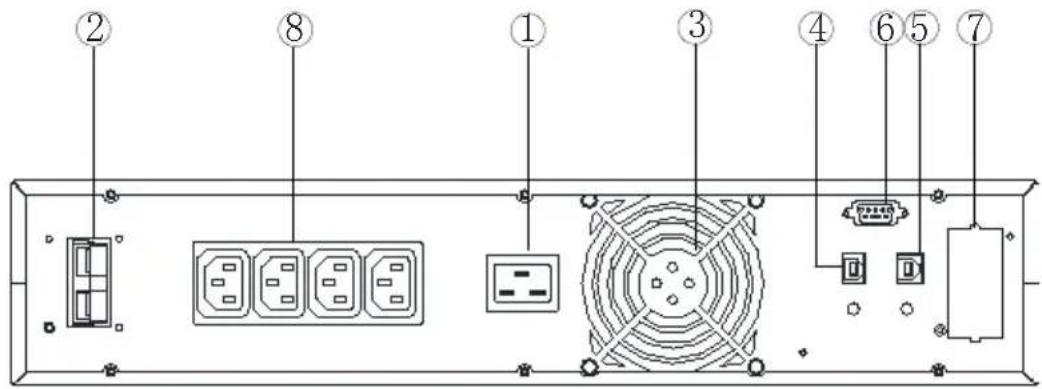
a. EG-UPSO-RACK-1000 (DC24V) rear panel
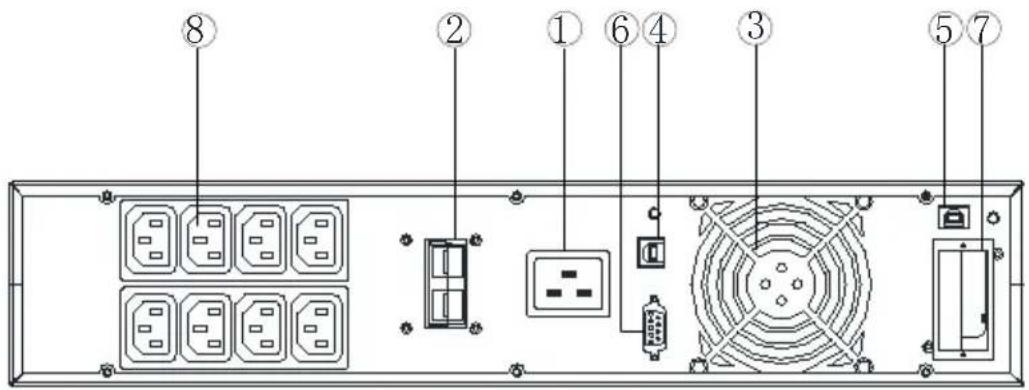
b. EG-UPSO-RACK-2000 (DC48V) rear panel

c. EG-UPSO-RACK-3000 (DC72V) rear panel
| 1 AC input socket | 6RS232 port |
| 2Battery connector | 7Intelligent slot |
| 3 Fan | 8Output sockets |
| 4 USB port | |
| 5EPO (Emergency Power Off) port |
Note:
The figure is for reference only. Due to the technology upgrading and development, the real unit might be different from the figure.
3 Installation
3.1 Unpacking inspection
- Open the UPS package and inspect the contents upon receipt. The accessories attached to the UPS contain a power cord, a user manual, communication ca CD-ROM. The long backup model also includes the cable for connection to b bank.
- Check if the unit is damaged during transport. Do not power on and notify the carrier and dealer if find damaged or parts missing.
- Verify this unit is the model you want to buy. Check the model name shower on the front panel and rear panel.
Note:
Keep the packaging box and packaging materials for future transport use. The equipment is heavy. Always handleit with care.
3.2 Installation information
- The UPS installation environment must be in good ventilation, away from water flammable gases and corrosive entities.
- Do not lie down the UPS against the wall so that front and side panel air rear panel air outtake hole will be unobstructed.
- The ambient temperature around the UPS should be within 0°C\~40°C (non-condensing).
- If dismantling the machine at low temperatures, there may be condensation droplets, users can not install or operate it before UPS completely got dry bed inside and outside, otherwise there will be danger of electric shocks.
- Place the UPS near the mains source so that can cut off utility power without delay in case of emergency.
- Make sure the load connected to the UPS is off when users connect it to U then turn on the load one by one later.
- Connect the UPS with the power outlet which is over-current protected. Do not connect the UPS with power outlets whose rated current is less than the main input current of this UPS.
- All power outlets should be configured with earthing device for safety.
-
UPS could be electrified or powered no matter the input power cord is tied c even when the UPS is off. The only way to cut off the output is switching of and disconnecting the mains power supply.
-
For all standard model UPS, it is advised to charge the batteries over 8 hours before using. Once the AC mains power energizes the UPS, it will automatically charge the batteries. Without prior charging, UPS output remains as usual but shorter back-up time than normal.
- When connected to motor, display equipment, laser printer etc., UPS power selection should be based on the startup power of the load which is usually as rated power.
- Wiring by a qualified electrician is required. Ensure input cables and output ca are connected correctly and firmly.
- If install a leakage current protective switch, please install it on output cable.
3.3 Installation and output connection
Normally, output connection of 1\~3kVA series is configured with power outlets or terminal blocks, users can plug the load cable into the UPS power outlets to enable the load. Make sure the mains cable and breakers in the building are enough that rated capacity of UPS to avoid the hazards of electric shock or fire.
3.4 Standard Model Built-in Battery Pack Installation Guide
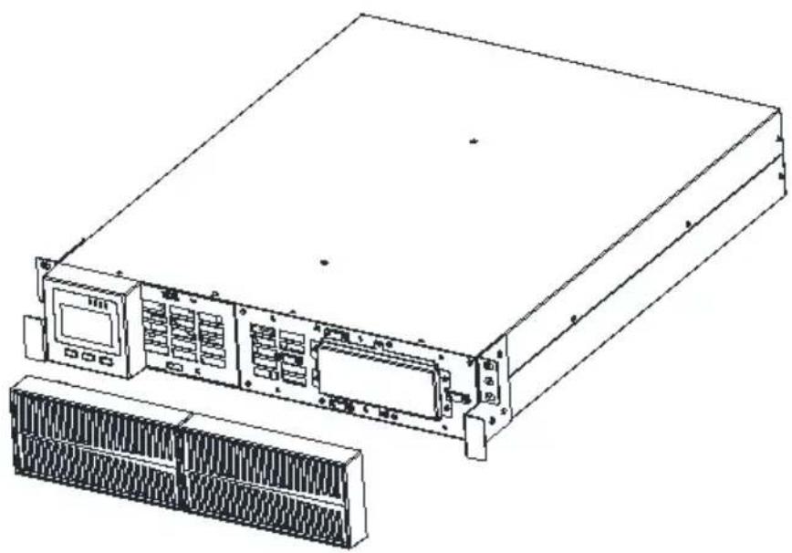
Step 1 Make sure the UPS is in mains mode, remove the two plastic panels of front.
natural_image
Line drawing of a server rack unit with front panel and rear panel, no text or symbols presentStep 2 Remove the two baffles in the picture below with a screwdriver.
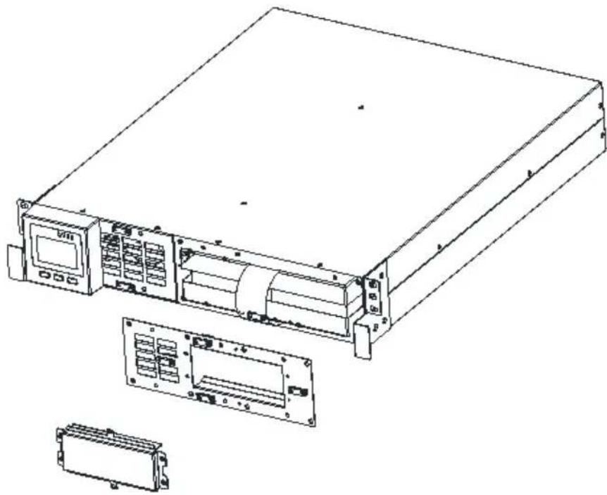
natural_image
Technical line drawing of a server rack with front panel, internal components, and external housing (no text or symbols)Step 3 Separate the battery terminals, pull the plastic handle of the battery pack drag the battery pack out.
Note: The battery pack is heavy. Please pay attention to safety when taking battery pack to prevent foot injury.

natural_image
Line drawing of a server rack unit with ports and connectors (no text or symbols)Step 4 After replacing the battery, put the battery pack back into the UPS. After connecting the battery terminals, lock the two baffles and cover the plastic panel
4 Network Functions
4.1 Communication port
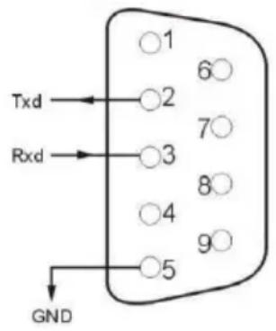
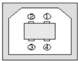
Users could monitor the UPS system through the communication port such as standard RS232 port and USB port with computer. Connecting this UPS with computer by communication cable could achieve UPS management easily.
RS232 port:
| Pins | 1 | 2 | 3 | 4 | 5 | 6 | 7 | 8 | 9 |
| Indication | empty | send | receive | empty | ground | empty | empty | empty | empty |
Note:
RS232 interface is set as below:
- Bit rate: 2400 bps
- Byte: 8bit
• Completion code: 1 bit - Bit pattern: None
USB port:
| Pins | 1 | 2 | 3 | 4 |
| Indication | +5V | date+ | date- | GND |
natural_image
Pure electrical component diagram without any text, numbers, or symbols4.2 EPO port (optional)
EPO is the short for Emergency Power Off. EPO on the rear panel of the UPS. It's green. Users off the output of UPS immediately by operating EF in case of emergency.

Normally, pin1 and pin2 are connected so that the machine can be working nor. When some emergencies happen, and when users have to cut off the output, just need to disconnect the connection between pin1 and pin2, or just pulling it out.
4.3 Intelligent card (optional)
There is an intelligent slot on the rear panel of the UPS, it's for SNMP card a contacts. Users can insert any type intelligent card from those three into it to n
and manage the UPS. And users don't have to turn off the UPS when install it intelligent card. Follow below process:
- First of all, remove the intelligent slot cover;
- Then insert the intelligent card (SNMP card and dry contacts);
• Finally, screw the intelligent card back.
> SNMP card (optional)
SNMP card on UPS is compatible with the most software, hardware and network operating system, it is a network management of UPS, with this function, UPS (login on internet, which can supply information of UPS status and input power, even possible to control UPS via net management system.
> Dry contacts card (optional)
Insert the dry contacts card into the intelligent slot. It's another type function of intelligent monitoring.
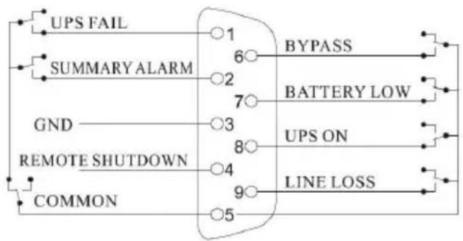
flowchart
graph TD
    A["UPS FAIL"] --> B["1"]
    C["SUMMARY ALARM"] --> D["2"]
    E["GND"] --> F["3"]
    G["REMOTE SHUTDOWN"] --> H["4"]
    I["COMMON"] --> J["5"]
    B --> K["BYPASS"]
    D --> L["BATTERY LOW"]
    F --> M["UPS ON"]
    H --> N["LINE LOSS"]
| Position | Definition |
| PIN1 | ON: UPS is malfunctioning |
| PIN2 | ON: Alarm (system failure) |
| PIN3 | Ground |
| PIN4 | Remote shutdown |
| PIN5 | Common |
| PIN6 | ON: Bypass mode |
| PIN7 | ON: Battery low |
| PIN8 | ON: Inverter mode;OFF: Bypass mode |
| PIN9 | ON: No AC power in |
5 Operation
5.1 Button operation
| Button | Function |
“ON” key | Press the two keys for more than half a second to turn on the |
“OFF” key | Press the two keys for more than half a second to turn off the |
TEST/MUTE key | Press the two keys for more than 1 second in Line mode or E CUCF mode: UPS runs the self-test function.Press the two keys for more than 1 second in battery mode: UI mute function. |
INQUIRING key | Not in setting mode:Press for more than half a second (less than 2 seconds): display the items orderly.Press for more than 2 seconds: Circularly and orderly display the items every 2 seconds, when press the key for some time will turn to output status.In setting mode:Press for more than half a second (less than 2 seconds): Select the setting option. |
FUNCTION SETTINGSkey | Not in setting mode:Press the key for more than 2 seconds: Function settings interIn setting mode:Press the key for more than half a second (less than 2 secor the function setting options.Press the key for more than 2 seconds: exit from this function interface. |
5.2 Display interface

| Display | Function |
| Icon display | |
 | Load icon:The approximate load capacity percentage (0-25%, 26-50% 51-75%and 76-100%) is indicated by the number of load bar sectio illuminated.When UPS is overloaded, the load iconwill flash. |
 | Mute icon: Indicates the audible alarm is disabled / mute.Press the mute key in the battery mode, themute icon flash. |
 | Fan icon:Indicates fan working status. When the fan normally runs, displays rotation; if the fan is not connected or faulty, the icon will |
 | Fault icon:Indicates UPS is in fault mode. |
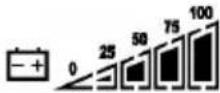 | Battery status icon: Indicates the battery capacity of 0-25%, 26-50% 51-75%, and 76-100%. When the capacity of battery get low or ba disconnected, the batterystatus iconwill flash. |
| UPS status information | |
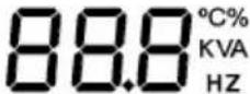
 | In non-setting mode, it displays UPS output information when UPS normally runs; Fault code will be told in fault mode.In setting mode, users could adjust different output voltage, activa mode, activate CUCF mode, select an ID number and so on by function setting keys and inquiring key. |
 | |
| Operation mode | |
 | Indicates the power capacity of UPS within 20 secondsafter starting IndicatesUPS operation mode in 20 seconds,such as STDBY (standb mode), BYPASS (Bypass mode), LINE (AC mode), BAT (Battery mo BATT (Battery Self Test mode), ECO (Economic mode), SHUTDN (Shutdownmode), CUCF (Constant Voltage and Constant Frequency mode). |
| LED indicator light functions | |
 | They are respectively inverter light and fault light from left to right.The inverter light (green LED indicator light) illuminates continuously: indicates that UPS is in mains mode or ECO mode or power sup battery mode.The fault light (red LED indicator light) illuminates continuously: it in that UPS is in fault status.Note: For LED indication in different modes, please refer to LED/dis panel and alarm list. |
5.3 UPS On/Off operation
| Operation | Description |
| Turn on the UP | > Turn on the UPS with mains powerWith mains power connected, UPS works in bypass mode, its output as the input voltage within the input range. If there is no need of voltage when mains power connected, you can set up bPS to 'OFF' bPS is ON, it means there is bypass output when power on.Press the ON key for more than half a second to start the UPS, t start the inverter.Once started, the UPS will perform a self-test function. When the se finishes, it will turn to online mode.> Turn on the UPS by battery without mains powerWhen main power is disconnected, press the ON key for more than second to start UPS.The operation of UPS startup process is almost same as above pro mains power. After the self-test finishes, UPS will work in battery mo |
| Turn off the UP | > Turn off the UPS in Line modePress the OFF key for more than half a second to turn off the UPAfter UPS shutdown, there is no output. If output is needed, you ca 'ON' on LCD setting menu.Turn off the UPS in battery mode without mains powerPress the OFF key for more than half a second to turn off the UPWhen UPS shutdown, it will do self-test first, until there is no displ panel. |
| UPS self-test/mute test operation | When UPS is in LINE Mode, press the self-test/mute key for more t second. UPS gets to self-test mode and tests its status. It will exit automatically after finishing test.When UPS is in BAT Mode, press the self-test/mute key for more t second, the buzzer stops beeping. If you press the self-test/mute key more second, it will restart to beep again. |
| UPS Setting | Enter Setup interface. Press and hold the function setting key for mo than 2 seconds, then come to Setup interface, press and hold the i key ( , ) for more than half a second(less than 2 seconds), select the function setting, choose the setup interface, at the moment, the flash.Enter thesetup interface. Press and hold the function setting key for more than half a second(less than 2 seconds), then come to the se interface, at this time, the letters doesn'tflash any more,the numerical flash. Press and hold the inquiring key ( , ) for more than second (less than 2 seconds), select the numerical value in accordar the function.Confirm the setup interface. After selecting numerical value, press and the function setting for more than half a second (less than 2 sNow, the setting function is completed and the numerical value illumi without flashing.Exit from the setup interface. Press and hold function setting key for more than half a second (less than 2 seconds), exit from the setup and return to the main interface.Note:UPS could not be set until it is connected to the battery and it is switched to Stdby mode (standby mode).Disconnect mains power after setting.The LCD display screen will automatically extinguish in about 1 min, setting will be configured normally. |
5.4 UPS Settings
• Output voltage setting
| LCD display | Settings |
 | For 208/220/230/240 VAC models, you may choose the following output voltage:208: output voltage is 208Vac220: output voltage is 220Vac230 (default): output voltage is 230Vac240: output voltage is 240Vac |
● Low voltage of battery setting
| LCD display | Settings |
 | The battery voltage selecting interface. You may choose following output voltage:9.8: Low voltage of battery is 9.8Vdc9.9: Low voltage of battery is 9.9Vdc10: Low voltage of battery is 10Vdc10.2: Low voltage of battery is 10.2Vdc10.5: Low voltage of battery is 10.5VdcdEF(default):EOD voltage automatically varies with loads including 20 hours discharge protection |
- Bypass mode setting
| LCD display | Settings |
 | Enable or disable Bypass function. You may choose the following two options:ON: Bypass enableOFF (default): Bypass disable |
- AUO setting
| LCD display | Setting |
 | AUO setting only can be set in Stdby mode or Bypass You may choose the following two options:ON: UPS will start up automatically and works in Line when connect mains.OFF (Default): UPS won’t start up automatically when connect mains except EOD, it will work in standby or mode. |
5.5 Parameters inquiring operation
Press the inquiring key or for more than half a second (less than 2 seconds) to inquire about items. The inquired items include Input, Battery, Output, Load and Temperature. The displayed items on LCD screen are shown as following:
| LCD display | Description |
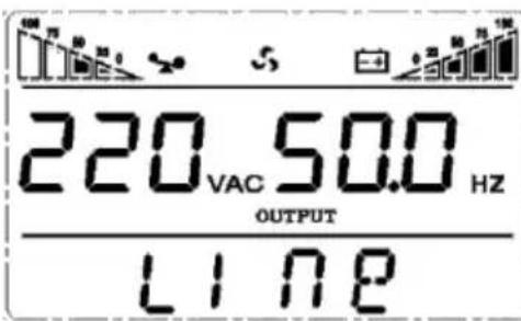 | Output: Display the output voltage and output frequent the UPS. As the following graphic shows, the output voltage is 220V, the output frequency is 50Hz. |
 | Load: Display the numerical value of the active power (WATT) and apparent power (VA) of the load. For e as the following graphics shows, the WATT of the Io 800W, VA is 1.0kVA (when disconnect loads, it is a phenomenon to show a small numerical value of WA and VA). |
 | Version and Temperature: Indicate firmware version ofUPSanddisplay the highest temperature of UPS components; As the following graphics shows, the firmware version is v1.7, the maximum temperature is 40°C. |
 | Input: Display the voltage and frequency of the input the following graphics shows, the input voltage is 22 input frequency is 50Hz. |
 | Battery: Display the voltage and capacity of the batt the following graphics shows, the battery voltage is 2 the capacity of battery is 100% (the capacity of batt approximately reckoned according to the battery voltage |
 | Warning: Display the warning code. |
5.6 Operation mode
| Operation mode and LCD display | Description |
Bypass mode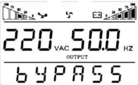 | Turn to bypass mode under the following three condConnect mains power and the bypass setup is OTurn off the UPS in line mode and the bypass ON.Overload in line mode.Note:When UPS is working in bypass mode, it has no back up function. |
Line mode | Being in line mode are as following: When input ma corresponding to the working conditions, UPS will wo line mode, LCD displays ‘Line’. |
Stdby mode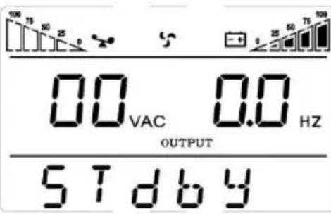 | UPS is powered off and no output supply power, bu can charge batteries. |
Battery mode | Being in battery mode are as following: the buzzer I once every 4 seconds.When the mains power is low or unstable, UPS will battery mode at once, and LCD displays ‘batt’. |
ECO mode | Being in ECO mode are as following: When the inp mains meet the input range of the ECO mode and function is on, the UPS works in ECO mode. If inp exceed the range of ECO several times within one but stays in inverter input range, UPS will work in i mode automatically. LCD displays ‘ECO’. |
CUCF mode | Frequency conversion mode is mainly to provide a s voltage and frequency (mainly in terms of frequency). starting this mode, its output will not be affected by meet input needs of some precision equipment and users' load more stable and secure. After opening C mode setup, LCD displays 'CUCF'. In CUCF mode, loading capacity will drop to 70% of the original capacity.The output frequency is fixed at the setting it doesn't vary with utility change. And the UPS can set to bypass mode in this mode. |
| Fault mode\( \begin{array}{c}\Delta \\|\\|\\|\\|\\|\\|\\|\\|\\|\\|\\|\\|\\|\\|\\|\\|\\|\\|\\|\\|\\|\\|\\|\\|\\|\\|\\|\\|\\|\\|\\|\\|\\|\\|\\|\\|\\|\\|\\|\\|\\|\\|\\|\\|\\|\\|\\|\\|\\|\\|\\| \\|\\|\\|\\|\\|\\|\\|\\|\\|\\|\\|\\|\\|\\|\\|\\|\\|\\|\\|\\|\\|\\|\\|\\|\\|\\|\\|\\|\\|\\|\\|\\|\\|\\|\\|\\|\\|\\|\\|\\|\\|\\|\\|\\|\\|\\|\\|\\|\\|\\-\\|\\|\\|\\|\\|\\|\\|\\|\\|\\|\\|\\|\\|\\|\\|\\|\\|\\|\\|\\|\\|\\|\\|\\|\\|\\|\\|\\|\\|\\|\\|\\|\\|\\|\\|\\|\\|\\|\\|\\|\\|\\|\\|\\|\\|\\|\\|\\|\\|\\- \\|\\|\\|\\|\\|\\|\\|\\|\\|\\|\\|\\|\\|\\|\\|\\|\\|\\|\\|\\|\\|\\|\\|\\|\\|\\|\\|\\|\\|\\|\\|\\|\\|\\|\\|\\|\\|\\|\\|\\|\\|\\|\\|\\|\\|\\|\\|\\|\\|\\ |\\|\\|\\|\\|\\|\\|\\|\\|\\|\\|\\|\\|\\|\\|\\|\\|\\|\\|\\|\\|\\|\\|\\|\\|\\|\\|\\|\\|\\|\\|\\|\\|\\|\\|\\|\\|\\|\\|\\|\\|\\|\\|\\|\\|\\|\\|\\|\\|\\|\\/\\|\\|\\|\\|\\|\\|\\|\\|\\|\\|\\|\\|\\|\\|\\|\\|\\|\\|\\|\\|\\|\\|\\|\\|\\|\\|\\|\\|\\|\\|\\|\\|\\|\\|\\|\\|\\|\\|\\|\\|\\|\\|\\|\\|\\|\\|\\|\\|\\|\\ | |
6 Fault Messages
Table 1: Fault code messages
| S/N | Working status | LCD display messages | Alarm beep | LCD flashes | LED flashes | |
| Inverter | Fault | |||||
| 1 | Inverter mode (mains power) | |||||
| Mains power voltage | Working mode displays Line | No beep | No flash | Flash always | / | |
| Mains power high/low voltage protection, switch to battery mode | Working mode displays bAT | One beep /4 sec | One flash / 4 sec | One flash / sec | / | |
| 2 | Battery mode | |||||
| Battery voltage - normal | Working mode displays bAT | One beep / 4 sec | One flash /4 sec | One flash / sec | / | |
| Warning for abnormal voltage of battery | Working mode displays bAT, Bat flash | One beep / sec | One flash /sec | One flash / sec | / | |
| 3 | Bypass mode | |||||
| Mains power - normal (under Bypass) | Working mode displays byPASS | One beep / 2 min | No flash | One flash /2 sec | / | |
| 4 | Warning for battery disconnected | |||||
| Bypass mode | Working mode displays byPASS, bat display is 0, and flash all the tir | One beep / 4 sec | One flash / 4 sec | One flash /2 sec | / | |
| Inverter mode | Working mode displays Line, bat display is 0, and flash all the time | One beep / 4 sec | One flash / 4 sec | Flash always | / | |
| Power on / Switch on | LCD illuminates when power on, and display the capacity of the UP later working mode displays Line or byPASS, bat icon flash all the time | 6 beeps | Flash always | Flash always | Flash always | |
| / | / | |||||
| 5 | Output overload protection | |||||
| Warning for mains power overload | Working mode displays Line, load icon flash | 2 beeps / sec | 2 flashes /sec | Flash always | / | |
| Protect operation for mains power mode overload | Working mode displays FAULT and the corresponding codes | Long beep | Flash always | / | Flash always | |
| Warning for battery | Working mode displays | 2 beeps / | 2 | One | / | |
| overload | bAT, load iconflash | sec | flashes/sec | flash / sec | ||
| Protect operation for battery mode overload | Working mode displays FAULT and the corresponding codes | Long beep | Flash always | / | Flash always | |
| 6 | Warning for bypass mode overload | Working mode displays byPASS, load iconflash all the time | One beep / 2 sec | One flash / 2 sec | One flash /2 sec | / |
| 7 | Fans fault(fan icon) | Fan icon flash, working mode displays depending on current mode | One beep / 2 sec | No flash | / | / |
| 8 | Faults mode | Working mode displays FAULT, numerical value area displays th corresponding error code | Long beep | Flash always | / | Flash always |
Note:
- End user need to provide below information when require to maintain the UPS
- UPS Model No. & Serial No.
- Date of fault occurrence.
- Fault details (LCD status, noise, AC power situation, load capacity, battery cap configuration ect.)
Table 3: Alarm code display
The alarm code will be displayed in four digital tubes on the right of the number of the LCD screen(red mark), as shown below:

The alarm truth table during operations is shown as below:
• signifies the alarm occurs, blank signifies no alarm appears
| The first digital tube from right to | Display value | Bypass lost | Remote Shutdown | Overload | Batterydisconnected |
| 0 | |||||
| 1 | ● | ||||
| 2 | ● | ||||
| 3 | ● | ● | |||
| 4 | ● | ||||
| 5 | ● | ● | |||
| 6 | ● | ● | |||
| 7 | ● | ● | ● | ||
| 8 | ● | ||||
| 9 | ● | ● | |||
| A | ● | ● | |||
| B | ● | ● | ● | ||
| C | ● | ● | |||
| D | ● | ● | ● | ||
| E | ● | ● | ● | ||
| F | ● | ● | ● | ● | |
| The second digital tube from right to left | Display value | Overcharging warnings | Mains reverse | Start-up abnormal | Charger fault |
| 0 | |||||
| 1 | ● | ||||
| 2 | ● | ||||
| 3 | ● | ● | |||
| 4 | ● | ||||
| 5 | ● | ● | |||
| 6 | ● | ● | |||
| 7 | ● | ● | ● | ||
| 8 | ● | ||||
| 9 | ● | ● | |||
| A | ● | ||||
| B | ● | ● | ● | ||
| C | ● | ● | |||
| D | ● | ● | ● | ||
| E | ● | ● | ● | ||
| F | ● | ● | ● | ● | |
| The third digital tube from right to left | Display value | EEPROM abnormal | Fan abnormal | Low battery | Median abnormal |
| 0 | |||||
| 1 | ● | ||||
| 2 | ● | ||||
| 3 | ● | ● | |||
| 4 | ● | ||||
| 5 | ● | ● | |||
| 6 | ● | ● | |||
| 7 | ● | ● | ● | ||
| 8 | ● | ||||
| 9 | ● | ● | |||
| A | ● | ● | |||
| B | ● | ● | ● | ||
| C | ● | ● | |||
| D | ● | ● | ● | ||
| E | ● | ● | ● | ||
| F | ● | ● | ● | ● | |
| The fourth digital tube from right to left | Display value | Over load fault | Mains lost | Bypass abnormal | |
| 0 | |||||
| 1 | ● | ||||
| 2 | ● | ||||
| 3 | ● | ● | |||
| 4 | ● | ||||
| 5 | ● | ● | |||
| 6 | ● | ● | |||
| 7 | ● | ● | ● |
Example:
If the alarm code "2000" appears on the LCD screen, it indicates loss of mains pow
7 Troubleshooting
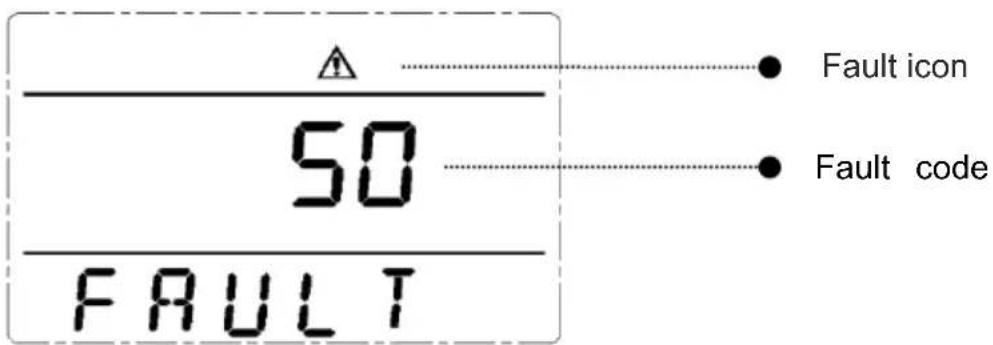
When the system works in fault mode, the LCD displays as below:
| Problem | Possible Cause | Solution |
| Fault icon display, audible buzzer alarm continually, the fault code is 00-14 | Bus voltage fault | Test the bus bar voltage or contact supplier. |
| Fault icon display, audible buzzer alarm continually, the fault code is15-24 | Soft start fault | Check the soft start circuit, especially the input fuse or contact the suppli directly. |
| Fault icon display, audible buzzer alarm continually, the fault code is 25-39 | Inverter voltage fault | Contact the supplier. |
| Fault icon display, audible buzzer alarm continually, the fault code is 40-44 | Over heat | Be sure that the UPS arenot overloaded, and the fan vent is not obstructed, as well as the indoor temperature is not high.Leave alone the UPS 10 minutes f cooling, and restart it. If the problempersists, contact the supplier. |
| Fault icon display, audible buzzer alarm continually, the fault code is 45-49 | Output short | Turn off the UPS and disconnect a loads.Be sure there is no any fault internal short circuit of the loads.And then restart the UPS. If the problempersists, contact the supplier. |
| Fault icon display, audible buzzer alarm continually, the fault code is 50-54 | Overload | Check the load level and disconnect the non-critical equipments, recount the total capacity of your load and reduce the load to the UPS.Check whether the load equipments has fault or not. |
| Fault icon display, audible buzzer alarm continually, the fault code is 55-59 | Bus short | Contact the supplier. |
| Fault icon display, audible buzzer alarm continually, the fault code is 60-64 | Shutdown fault | Check the first button of the LCD is pressed and cannot be bounced |
| Fault icon display, audible buzzer alarm continually, fan icon in the LCD flickers | Fan fault | Check whether the fans are connec and fixed well or not, and if fansa broken. If all seems fine, contact th supplier. |
| UPS fail to start when opera ‘On’ key | Pressing time too short | Press the power key more than 2 seconds to start the UPS. |
| The input connection is not ready or | Connect the input well, if the batter voltage is too low, disconnect the i | |
| UPS internal battery disconnect | and start the UPS with no-load. | |
| UPS internal system fault | Contact the supplier. | |
| Back up time become short | Battery undercharge | Keep the UPS battery recharging m than 3 hours |
| UPS overload | Check the load level and disconnect the non-critical equipments, | |
| Battery maturing, capacity descend | Replace with new batteries, contact supplier to get the new batteries ar spare parts. | |
| UPS doesn't have any power going through even mains power on | UPS input breaker disconnected | Reset the circuit breaker by manual |
Note:
When the output is short-circuited, the action of UPS protection will show up. B turning off the UPS, make sure to disconnect the entire loads and cut off the power supply, otherwise it will make the AC input shortcircuit.
8 Software Download & Installation
(Only for the model with communication port)
Please follow steps below to download and install monitoring software :
- Go to the website https://www.idbkmonitor.com
- Click UPSSmartView software icon and then choose your required OS to do the software
- Follow the on-screen instructions to install the software
- Safety Information....1
- Product Overview....3
- Installation....6
- Network Functions....9
- Operation....11
- Fault Messages....18
- Troubleshooting....22
- Software Download & Installation....24
- Safety Information
- UPS safety information
- CAUTION
- Battery safety information
- Product Overview
- Front panel features
- Rear panel features
- Note:
- Installation
- Unpacking inspection
- Installation information
- Installation and output connection
- Standard Model Built-in Battery Pack Installation Guide
- Network Functions
- Communication port
- EPO port (optional)
- Intelligent card (optional)
- > SNMP card (optional)
- > Dry contacts card (optional)
- Operation
- Button operation
- Display interface
- UPS On/Off operation
- UPS Settings
- - Bypass mode setting
- - AUO setting
- Parameters inquiring operation
- Operation mode
- Fault Messages
- Troubleshooting
- Software Download & Installation
Brand : EnerGenie
Model : EG-UPSO-RACK-3000
Category : Uninterruptible power supply