EG-PMS2-LAN - Socket EnerGenie - Free user manual and instructions
Find the device manual for free EG-PMS2-LAN EnerGenie in PDF.


| Product Type | Smart Power Strip with LAN Control |
| Model | EG-PMS2-LAN |
| Brand | EnerGenie |
| Socket Type | EU / UK / US (depending on region) |
| Number of Outlets | 4-6 (typical) |
| Dimensions (Approx.) | 200 x 60 x 30 mm |
| Weight (Approx.) | 300 g |
| Input Voltage | 100-240 V AC, 50/60 Hz |
| Maximum Load | 10 A (2200 W at 220 V) |
| Connectivity | Ethernet (LAN) port for network control |
| Control Interface | Web interface, mobile app (EnerGenie), API |
| Key Functions | Remote on/off, scheduling, energy monitoring, surge protection |
| Energy Monitoring | Real-time power consumption per socket |
| Surge Protection | Integrated surge protector (max 6000 V) |
| Overload Protection | Automatic shutdown if load exceeds rated limit |
| Maintenance & Cleaning | Wipe with a dry cloth; do not use liquids |
| Safety Certifications | CE, RoHS compliant |
| Operating Temperature | 0°C to 40°C |
| Spare Parts & Repairability | No user-serviceable parts; contact support for repairs |
| Package Contents | Power strip, user manual, Ethernet cable |
Frequently Asked Questions - EG-PMS2-LAN EnerGenie
User questions about EG-PMS2-LAN EnerGenie
0 question about this device. Answer the ones you know or ask your own.
Ask a new question about this device
Download the instructions for your Socket in PDF format for free! Find your manual EG-PMS2-LAN - EnerGenie and take your electronic device back in hand. On this page are published all the documents necessary for the use of your device. EG-PMS2-LAN by EnerGenie.
USER MANUAL EG-PMS2-LAN EnerGenie
natural_image
Abstract logo design featuring stylized lowercase 'e' with a circular element and a small letter 'g' on the top right (no text or symbols beyond the graphic elements)www.energenie.com
natural_image
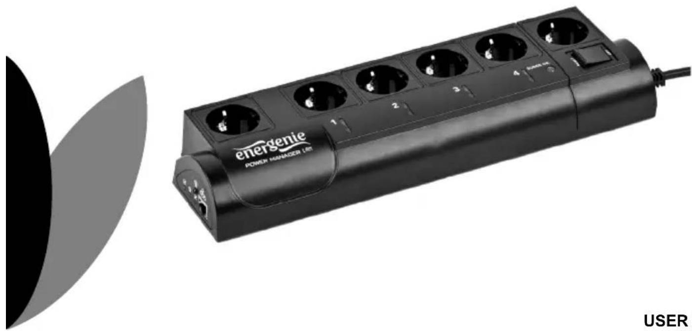
Exterior view of a black power manager utility pole with multiple charging outlets and a USB cable (no text or symbols on the main body)EG-PMS2-LAN PROGRAMMABLE SURGE PROTECTOR WITH LAN INTERFACE
USER MANUAL
HANDBUCH
HANDLEIDING
MANUEL DESCRIPTIF
- Do not plug several sockets in line
- Do not use if covered
- De-energized only if power plug is unplugged
- NEVER connect appliances which do not allow unattained operation!

2
All brands and logos are registered trademarks of their respective owners
1. Introduction
Congratulations with your purchase of this Programmable LAN Surge protector. Your EG-PMS2-LAN is an advanced surge protector with power management features. Four sockets are individually manageable via the LAN interface.
The sockets can be switched on/off by a timer schedule, by user or different events. It is also possible to pre-program the unit event timer schedule (hardware schedule) and then disconnect EG-PMS2-LAN from LAN and use it elsewhere. The device can be used as an advanced standby-killer.
With your free personal user account at EnerGenie.com you can manage your EG-PMS2-LAN via the Internet from all over the world, even from your Smartphone.
1.1. Features
- Switch individual sockets on/off manually from your computer
- Switch individual sockets on/off by a programmable timer schedule
- Switch individual sockets on/off whenever a certain software event occurs (e.g. Windows/other software start-up/shutdown, print spooler starting and finishing its job, etc)
-
Because of the LAN interface and the built-in web-server, EG-PMS2-LAN can be accessed from any computer within your local network (via an Internet browser or Power manager software)
-
It is also possible to assign an external IP-address to EG-PMS2-LAN, to enable worldwide remote access via the Internet
- No external IP-address at home? No problem. Create your own user account on EnerGenie.com to manage your EG-PMS2-LAN via Internet with any PC or smartphone. Switching on your coffee maker before setting off for home becomes a reality.
- IP-filter 64-bit password protected data encryption guarantees secure Internet access to EG-PMS2-LAN
- EG-PMS2-LAN has a built-in battery for the timer schedule, so the timer schedule remains active even when EG-PMS2-LAN is temporarily turned off.
1.2. Specifications
• Input voltage: max 250 VAC, 50 – 60 Hz
• Maximum load current: 10 A
• Maximum power consumed by EG-PM2: 2.5 W
• Built-in power supply
• RJ45 LAN connector
- Surge: Type3, Up = 1.2 kV for L-N, Uoc = 4 kV for L-N Uo = 230 V
Uc = 250V Ucs = 1.1 x 230 V = 253 V
• Hardware schedule possibilities:
- Maximum number of independent hardware schedule events – 45 per socket
• Time setting accuracy in seconds
- Combine periodical and once events
- Timer accuracy: not more than 2 seconds error per day in case that power is always present. Otherwise there can be an additional up to 2 seconds error per each "power off"
- Indoor use only
• Dimensions: 378 x 100 x 57 mm - Net weight: 1 Kg
1.3. Hardware requirements
- Local area network with RJ45 sockets
- Any Internet-enabled computer connected to the local area network
- Computer running Windows® XP/Vista/7/8/10 is required for using the Power Manager software (use of this software is not compulsory)
1.4. Package contents
- EG-PMS2-LAN
- User manual and Quick installation guide
- RJ45 cross-over cable (red), RJ45 LAN cable (grey)
CD with Power Manager software for Windows can be downloaded here:


2. Indicators and controls of the EG-PMS2-LAN

All brands and logos are registered trademarks of their respective owners

All brands and logos are registered trademarks of their respective owners
Figure #3
All brands and logos are registered trademarks of their respective owners
2.1. Indicators
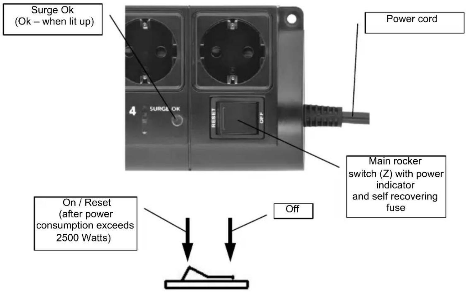
- Main rocker switch Z (see Figure #3 above) is lit – this means that EG-PMS2-LAN is connected to the power supply and active
- The indicator Socket 1 (2,3,4) (see Figure #1 above) is lit – this means that this particular socket is switched on
- The indicator LAN activity (see Figure #2 above) blinks green – this means that there is some LAN activity taking place
- The indicator Schedule (see Figure #2 above) blinks red as the reset procedure is being executed
- The indicator Schedule (see Figure #2 above) stays red if an active hardware schedule for any socket exists
- The indicator Surge Ok (see Figure #3 above) stays on if the surge protection is well functioning
3. Installation
- It is strongly recommended to avoid damp or wet places for installation.
- EG-PMS2-LAN should be connected to the European AC wall socket of the standard DIN 49 440
- Do not plug several sockets in line
- Do not use if covered
- De-energized only if power plug is unplugged
- NEVER connect appliances which does not allow unattained operation!
3.1. Getting started
- Connect EG-PMS2-LAN to the wall socket first and then to the LAN socket (or your computer LAN card) with the provided patch cord or vice-versa.
- EG-PMS2-LAN can now be switched on and off by means of the Main rocker switch (Z).
- Two non manageable sockets are switched on and off by means of the Main rocker switch (Z) and cannot be managed by the computer – so they are called non-manageable sockets in this manual.
-
If EG-PMS2-LAN is switched on then the red indicator POWER is lit. In this case both non-manageable sockets are now live and connected to the power supply.
-
The sockets: Socket 1, Socket 2, Socket 3 and Socket 4 can be managed or pre-programmed by computer via LAN. They are called manageable sockets in this manual.
- The manageable sockets of EG-PMS2-LAN can be programmed to be on or off. The current status of each manageable socket is represented by the corresponding indicator which will be lit if socket has power to it.
- If the Main rocker switch (Z) (see Figure #1 above) is turned off then the manageable sockets cannot be switched on by either web server, Power manager software or the hardware schedule.
- As soon as you turn the Main rocker switch (Z) on then the web server, Power manager software or the hardware schedule will be able to turn the manageable sockets on and off.
- Master switch button (B) (see Figure #2 above) can also switch all the manageable sockets on and off regardless of their current status or schedule that is being executed. To switch them on you should keep the button pressed for 1-2 seconds. To switch them off you should keep the button pressed for more than 3 seconds.
- To protect the connected devices from possible high current and short circuit EG-PMS2-LAN is equipped with the automatic circuit breaker built in Main rocker switch.
NOTE: If the total power consumption (or peak power) of the devices, connected to EG-PMS2-LAN exceeds 2500 Watts, the circuit breaker may power EG-PMS2-LAN off. In this case, please, remove the excessive load first and then (after 2-3 minutes) press the main rocker switch (Z) to restore the power supply (see Figure #3 above).
To be able to use EG-PMS2-LAN you will now have to complete its LAN configuration.
3.2. Preparing LAN configuration of EG-PMS2-LAN
Before configuring EG-PMS2-LAN hardware settings, please, let it obtain its IP address. Follow the steps below:
- Make sure EG-PMS2-LAN is connected to the local network with the provided RJ-45 cable (option A - recommended)
NOTE: by default the factory setting of EG-PMS2-LAN is DHCP enabled. If your LAN has a router with built-in DHCP server (which is very common) then EG-PMS2-LAN will automatically get an IP address from the DHCP server. Proceed to section 3.3 below in this case.
NOTE: you may prefer to connect EG-PMS2-LAN directly to the managing computer LAN adapter (network card) using the supplied crossover RJ-45 cable (option B). You might need to use this option if your LAN does not have DHCP server.
NOTE: The embedded EG-PMS2-LAN web server doesn't work correctly in dial-up modem connections. It is recommended to access it via broadband connections, in which the network equipment has MTU packet size is 1386 or more.
If you choose for option B then the following procedure is required to let EG-PMS2-LAN obtain a fixed IP address:
• Turn EG-PMS2-LAN on (with the Main rocker switch Z)
- Press IP Config (C) button on the side control panel (see Figure #2 above) with the tip of a pen
- While holding it pressed, press and release Reset (A) button and wait for about 3 seconds until you hear the sockets switching twice
The above-mentioned procedure forces EG-PMS2-LAN to reset itself to the default settings (see below) ...
• IP: 192.168.0.254
- Subnet mask: 255.255.255.0
• Gateway: 192.168.0.1
- DNS:0.0.0.0
- DHCP: enabled
• IP filtering: disabled
• Power Manager client port: 5000
• Web server port: 80
... EG-PMS2-LAN then searches for an IP address from your eventual DHCP server. If no DHCP server is found within 1 minute, EG-PMS2-LAN will then automatically revert to the default settings (see above, with IP: 192.168.0.254).
3.3. Power Manager installation
It is now time to identify which IP address has been obtained by EG-PMS2-LAN. We need to carry out the following:
- Insert the Power Manager CD into a PC CD-ROM drive. This PC can be connected either to the same LAN where the device is (if you chose option A section 3.2) or directly to the device with the crossover RJ-45 cable (if you chose option B section 3.2)
- If for any reason the automatic setup does not work, then open CD-ROM drive in the My Computer window and launch SETUP.EXE from the CD
- Follow instructions of the installation software
NOTE: Antivirus or firewall software may block connection to EG-PMS2-LAN. Please, configure antivirus/firewall to permit connection to the IP address and port of your EG-PMS2-LAN
3.4. IP configuration
The utility Find EG-PMS2-LAN (see Figure #4 below) will run automatically during the software installation but it can also be started from Start/All Programs/Gembird/Power Manager. The IP range where you would like to search for EG-PMS2-LAN will be set automatically according to the IP settings of your LAN adapter but can be changed manually in the Adapter subnet fields. Now press the Search button.
NOTE: only EG-PMS2-LAN within a local subnet can be found. If your computer LAN adapter is not in the (default) subnet of EG-PMS2-LAN (as might probably be the case if you chose option B section 3.2) you will have to change its IP address manually to be able to find EG-PMS2-LAN. For example if you wish to find EG-PMS2-LAN (with the default IP 192.168.0.254), the IP address of your computer should be set as 192.168.0.XXX (where XXX stands for any digit, for example 1) and the subnet mask should be 255.255.255.0.
After the searching the IP addresses of the found EG-PMS2-LAN devices will appear in the list box. Select EG-PMS2-LAN which you want to access, and press the Open button (see Figure #4 below).
Figure #4

The window of your default internet browser will be then opened to give you access to the built-in web-server. See section 4 below for the further details.
All brands and logos are registered trademarks of their respective owners
4. The web server
Your EG-PMS2-LAN is equipped with a web-server which allows managing the device using any web browser such as Internet Explorer, Firefox, Chrome, etc.
4.1. Web-server login page
To access the web server of EG-PMS2-LAN, just open Internet Explorer (or other browser) and input the IP address of EG-PMS2-LAN (for example http://192.168.1.241). If you have used Find EG-PMS2-LAN utility to locate EG-PMS2-LAN then you will be taken to this webpage automatically. Login page will then be displayed (see Figure #5 below).
NOTE: Java script must be enabled in your Internet Explorer (or another browser) settings. Otherwise, you get an error message: WARNING! JAVASCRIPT IS DISABLED!
Figure #5

The default password is 1. It is recommended to change the password on the Device settings page (see section 4.6 below) after the first login.
All brands and logos are registered trademarks of their respective owners
After a successful login you will face the EnerGenie page (see section 4.2 below).
NOTE: There is a possibility that you might then need to open the LAN settings page (see section 4.5 below) to complete the IP configuration.
4.2. EnerGenie page
With the help of EnerGenie page (see Figure #6 below) you will be able to see the status of all your four manageable sockets, and to switch the sockets on and off manually. The status of your sockets, as well as the buttons to switch them on/off are located at the top of the page.
NOTE: the names of the sockets can be changed from the default Socket1/Socket2/Socket3/Socket4 to something meaningful on the page Socket Name Settings (see section 4.4 below).
The EnerGenie page also allows you to setup access and management (switch on and off) of your EG-PMS2-LAN from anywhere via Internet even if it does not have an external IP address. To setup this free service you should follow two simple steps:
- Register the device. To restrict access to the device via the Internet to the rightful owner only, the device should be registered – e.g. assigned to your account. To register the device, simply push the button Register on this page (see Figure #6 below). You will then be redirected to Login page of EnerGenie.com. If you already own an account at EnerGenie.com then just enter your login and password on this page and you are done. Otherwise, use the Registration button on the Login page to create a new account. After your successful login (regardless whether you created a new or used an existing account) your EG-PMS2-LAN is automatically registered.
- Return back to the EnerGenie page of your EG-PMS2-LAN (see Figure #6 below). Push Activate button to let the device initiate communication with EnerGenie.com server. The EnerGenie page will then start updating itself until the Status becomes Registered Activated Connected (see Figure #6 below).
Figure # 6

All brands and logos are registered trademarks of their respective owners
After a successful registration and activation the button Register will be renamed to Login (and will then open the Login page of EnerGenie.com) and the button Activate will turn into Deactivate. If by any reason you would eventually decide to stop managing your EG-PMS2-LAN from Internet use then Deactivate button to stop communication of the device with EnerGenie.com server.
If you eventually decide to change registration of your EG-PMS2-LAN and assign it to another account, it will be possible via EnerGenie.com website (see section 5 below).
See section 5 below for further details on managing your EG-PMS2-LAN via EnerGenie.com website.
4.3. Socket page
There are 4 manageable sockets on EG-PMS2-LAN and so there are 4 pages corresponding to them. On each status page you can see the socket status (on or off) and you have the Switch On (Switch Off) button. Besides you can see the scheduled events for this socket. The socket number and its eventual name (see section 4.4 below) are shown at the very top of the page (see Figure #7 below).
Figure #7


Set schedule
Event schedule
| Event | Date/Time | |
| ON | Tue Jul 10 2012 14:20:00 GMT+0200 (W. Europe Daylight Time) | Periodic |
| OFF | Tue Jul 10 2012 14:30:15 GMT+0200 (W. Europe Daylight Time) | Periodic |
| ON | Mon Jul 09 2012 14:40:30 GMT+0200 (W. Europe Daylight Time) | |
| OFF | Mon Jul 09 2012 14:50:45 GMT+0200 (W. Europe Daylight Time) | |
Loop period: 1 days
Synchronized: Mon Jul 09 2012 12:37:00 GMT+0200 (W. Europe Daylight Time)
Mon Jul 09 2012 14:10:29 GMT+0200 (W. Europe Daylight Time)
The socket shown on the Figure #7 is currently off, it will be turned on again automatically on the 9th of July at 14:40:30 and on the same day at 14:50:45 it will be switched off. Next day it will be turned on at 14:20:00 and at 14:30:15 it will be switched off. Last two events will be executed each day staring from the 10^th of July.
All brands and logos are registered trademarks of their respective owners
Below the page you can see the current time of the web-server and eventual information about the last successful timer synchronization. Automatic timer synchronization is used if Use NTP for timer correction option is enabled (see section 4.6 below).
NOTE: If a certain socket has a switching fault, e.g. it should be switched on but the whole device is switched off, or it should be off but it does have voltage, then the warning message Wrong voltage on socket! will be shown above the Event schedule (see Figure #7 above). This message might also indicate that this socket is defective.
For setting up the socket schedule click Set schedule button. You will face then the page shown below (see Figure #8).
Figure #8


Choose the date and time of the scheduled event. If you wish the event to be executed periodically then choose Periodic option and set the loop period. To commit to your changes press the Apply button. To delete the entry press the x button. To delete the entered schedule press the Clear schedule button.
All brands and logos are registered trademarks of their respective owners
NOTE: The hardware schedule keeps running even when the device is powered off. However it is recommended not to power off the device for longer than 1 week, because the built-in battery might get discharged then. In this case the internal clock of the device would be reset and as result some schedule events would not be executed. Besides all the sockets would lose their previous status (they will be switched on). In case of an empty battery, just leave the device switched on for one day to fully charge the battery again.
4.4. Socket Name settings page
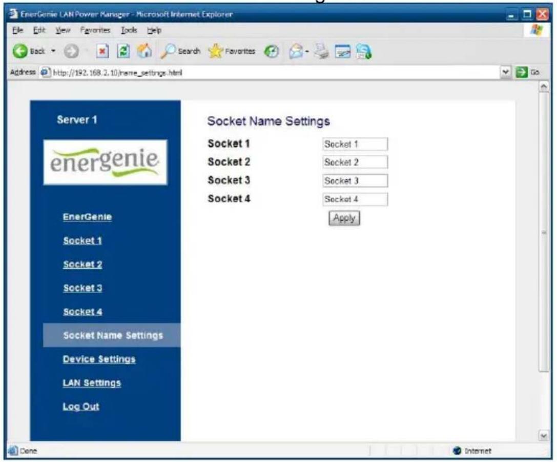
On the Socket name settings page (see Figure #9 below) you can assign an applicable name to your sockets. These names will be shown on EnerGenie page (see section 4.2 above) as well as on the Socket pages (see section 4.3 above).
NOTE: The socket names can not be longer than 11 characters.
HINT: Call your socket by the device which is attached to this socket. For example call Socket 1 – TV set if your TV is connected to this socket.
Figure #9
All brands and logos are registered trademarks of their respective owners
4.5. LAN settings page
Figure #10

All brands and logos are registered trademarks of their respective owners
On the LAN settings page (see Figure #10 above) you can set up DHCP, IP address, Subnet mask, Gateway, DNS server and IP filter (up to 3 IP addresses can then be enabled for remote access).
The new settings will be applied immediately after you press the Apply button.
IP address, Subnet mask, Gateway, DNS server will be used only if the DHCP option is disabled.
If you set DHCP option it is recommended for your own convenience to set up your DHCP server so that it always provides the same IP address to EG-PMS2-LAN. To do that you will need to know the MAC address of EG-PMS2-LAN. It can be found on this page or on the bottom sticker of the device. The MAC address is fixed and cannot be changed.
DNS server address is important to be properly set up in case you wish to enable the NTP timer correction option (see section 4.6 below).
IP filter option is needed to prevent unauthorized access to the server. It restricts the web server access from any computer with IP address different from IP1, IP2 and IP3. Make sure that you input IP1, IP2, and IP3 correctly before enabling this option.
Power Manager client port is used for connecting with the Power Manager software, normally it is not needed to change this setting.
Web server port is used for access the embedded EG-PMS2-LAN web server via browser, normally it is not needed to change.
When you click "Apply" button, new changes will be applied, the device will be reset, and login webpage will be opened. You will need waiting for a few seconds then refresh the webpage manually (by clicking "Refresh" button in the browser) or change IP address and web port in address field in the browser (in case that you have changed them). If you need just to reset the device, click "Apply" button with LAN settings unchanged.
4.6. Device settings page
On the device settings page you can setup name, password and internal time of EG-PMS2-LAN (see Figure #11 below).

Figure #11
To be able to setup the schedule of EG-PMS2-LAN you have to first setup its internal clock correctly. Enter the current local time and date.
All brands and logos are registered trademarks of their respective owners
Alternatively if the option Use NTP for timer correction is enabled (by default) then the time will be taken from NTP server. The device will try to connect with the server every 18 hours. The first synchronization would take place in 15 seconds after you press the Apply button.
NTP server field should have a valid name of NTP server (by default "pool.ntp.org"). If for any reason the NTP time correction doesn't work you can choose the best NTP server for your country via the website www.pool.ntp.org.
NOTE: for NTP time correction to work properly the device should have access to the Internet and have a proper DNS server setting (see section 4.5 above).
Server name can be convenient to identify the web server if you have more than one EG-PMS2-LAN. It is “Server 1” by default. The password is necessary to access EG-PMS2-LAN both from your web browser and the Power Manager software (see section 6 below). This password is case-sensitive and can be up to 32 characters long. Alphanumeric characters and spaces are allowed to be entered. Only the first eight characters of the password are used to access the device with the Power Manager software. You will need to enter this password in the Add LAN device window (see section 7 below).
The Power Manager software accesses EG-PMS2-LAN via a certain client port (by default 5000). You can change this port to any other except the port, which is occupied by the web server.
Don't forget to push the Apply button to save your settings.
4.7. Web-server logout
Having finished working with EG-PMS2-LAN, choose Log Out in the main menu. If you don't do this, you will be logged automatically after 10 minutes of inactivity. While you are logged to the web server, it can't be accessed from any other computer. If another user tries to access the web server which is running an active session the error message will be shown on the login page: Somebody with another IP has already logged in. Try again later. In the meantime the Power Manager software (see section 6) can still access the EG-PMS2-LAN.
5. EnerGenie.com device interface
With your free personal account at EnerGenie.com website you will be able to access your EG-PMS2-LAN from anywhere in the world using any Internet-enabled device (desktop PC, laptop, smartphone etc). See section 4.2 above on how to register your EG-PMS2-LAN on the server and setup the connection.
5.1. Logging in
To login into your EnerGenie account just open the webpage www.energenie.com/user in your Internet browser and enter your login and password in the login window (see Figure #12 below).
Figure #12

Check Remember me checkbox for automatic login in the future (the website will then save a cookie on your computer). If you lost your password, click Forgot password button.
5.2. Device management page
After a successful login you will see the list of your registered devices and their corresponding sockets (see Figure # 13 below).
All brands and logos are registered trademarks of their respective owners
Figure #13
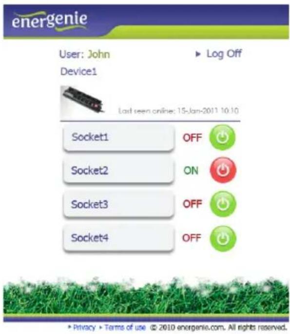
This page will automatically update itself and will keep showing you the time when your device was last seen online (the latest time when the device communicated with the server) and the status of each socket.
Click your user name to change your account settings.
Click the device to change its name and/or transfer it to another account.
All brands and logos are registered trademarks of their respective owners
Click the sockets to change their names
Click the On/Off buttons to switch the sockets on or off.
NOTE: the switching command can only be properly executed if the device is switched on, connected to the Internet and activated.
NOTE: the Last seen online status information lets you check if the device keeps communicating with the server.
6. Power Manager software
The Power Manager software is designed to support not only EG-PMS2-LAN but also other power management family products (please visit www.energenie.com).
6.1. Finding EG-PMS2-LAN
To be able to manage preconfigured EG-PMS2-LANs, please, do the following:
• Install Power Manager software on a PC connected to your local network. A socket icon will then appear in your system tray
- With a right mouse click on the socket icon you will get access to the Power Manager main menu (see Figure #14 below)
Figure #14
Please select Device – Add Device, or press [Ctrl+A] (see menu on Figure #15 below)
All brands and logos are registered trademarks of their respective owners
Figure #15
Add device... (Ctrl+A)
Remove Device (Del)
In the Add LAN device window (see figure #16 below) please, enter correct IP address, port number (5000 by default) and password (1 by default) as configured on the Device settings page (see section 4.6 above) of the web server. To disconnect from the device uncheck the option Enable, set this option again to regain the access. Click OK button to return to the LAN devices window.
Figure #16

Specified device should then appear with a green square next to it and Connected status in the LAN devices window (see Figure #17 below).
All brands and logos are registered trademarks of their respective owners
Figure #17

- To edit the LAN device, select it and click the Edit button, or just double click on the LAN device
- To remove the LAN device, select it and click the Remove button. You can select multiple LAN devices using Ctrl and Shift keys. You can also remove all LAN devices by clicking the Clear button
HINT: Use the popup menu which can be activated by the right mouse button click over the table.
If the status of EG-PMS2-LAN shows the device not to be Connected - it could be due to the following reasons:
- Incorrect IP/Port/Password specified in the Add LAN device window
• PC is not connected to the local network - You are trying to access EG-PMS2-LAN from the PC which is not allowed to do so. Change PC IP address or change IP filter list in EG-PMS2-LAN hardware settings (see section 4.5 above)
- EG-PMS2-LAN is not connected to local network. To check if EG-PMS2-LAN is on your local network you can do so-called ping test:
- Go to Start->Run
- Type cmd
- Type ping
in the window which would appear
Suppose EG-PMS-LAN with IP address 192.168.2.189 is connected to the local network. Then the cmd window will look as shown on the Figure #18 below:
Figure #18
![Administrator: C:\Windows\system32\cmd.exe Microsoft Windows [Version 6.0.6002] Copyright 2006 Microsoft Corporation. All rights reserved. C:\Users\Administrator>ping 192.168.2.189 Pinging 192.168.2.189 with 32 bytes of data: Reply from 192.168.2.189: bytes=32 time=ins TTL=128 Reply from 192.168.2.189: bytes=32 time](/content/2026/06/1373731/images/30dd7158affb95c70800ce6db3dfbc92b1d2307c7b30543b3a7b37c9fa51d821.jpg)
- EG-PMS2-LAN is connected to local network (ping test is ok) but not responding. Reset EG-PMS2-LAN by pressing the Reset button (A) on the side control panel (see Figure #2 above) or switch it off and then on again (see Figure #1 above)
NOTE: The Reset button A (see Figure #2 above) can sometimes help if EG-PMS2-LAN can't be accessed or works abnormally. The device will then be restarted. All the IP settings and device settings will remain the same as before, but the server time will be reset and all schedules will become outdated.
All brands and logos are registered trademarks of their respective owners
6.2. Managing EG-PMS2-LAN
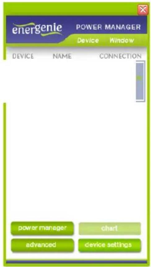
After successful connection, close LAN devices window. You can now start managing EG-PMS2-LAN via the Power Manager interface. Double click on the socket icon in the system tray or select Open from the popup menu (see Figure #14 above). You will get the window of the main control panel shown on the Figure #19 below.
Figure #19

flowchart
graph TD
    subgraph Power Management1
        A["Socket1"] --> B["Settings"]
    end
    subgraph Power Management2
        C["Socket2"] --> D["Settings"]
    end
    subgraph Power Management3
        E["Socket3"] --> F["Settings"]
    end
    subgraph Power Management4
        G["Socket4"] --> H["Settings"]
    end
    style Power Management1 fill:#f9f,stroke:#333
    style Power Management2 fill:#ccf,stroke:#333
    style Power Management3 fill:#cfc,stroke:#333
    style Power Management4 fill:#fcc,stroke:#333
Sockets should switch on and off (green color means the socket is switched on; red color means the socket is switched off) when you double
All brands and logos are registered trademarks of their respective owners
click on them. Click the Settings button for each socket to access the Settings dialog box (see Figure #20 below).
Figure #20
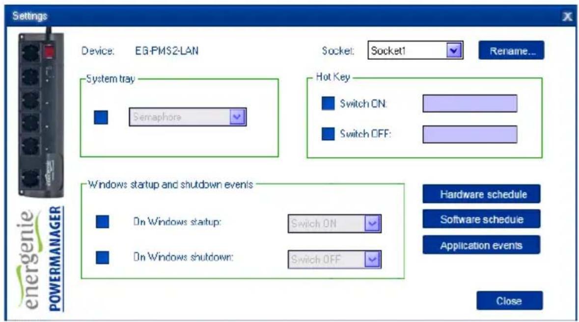
You can choose a different device and another socket from the Device and Socket drop down list-boxes.
- It is possible to give a name to the device and socket (for example Printer or Scanner) using the Rename button
- Check the System tray checkbox if you want to put the icon of the socket into the system tray. You can choose the icon from drop down list
box. Such icon is a fast way to switch the device connected to the socket on/off or check the device status
- You can also assign a hot key to switch the socket on/off. Check the Switch ON and Switch OFF checkboxes and specify the hot keys
- To switch the socket on/off on Windows startup (wake up), check the On Windows startup checkbox and choose the required action
- To switch the socket on/off on the Windows shutdown (sleep), check the On Windows shutdown checkbox and choose the required action
7. Power Manager core features
7.1. Setting up the hardware schedule
Using the Hardware schedule button available from the Settings window (see section 6.2 above) you can create the hardware timer schedule (see Figure #21 below). To add a new record, click the Add button.
Figure #21
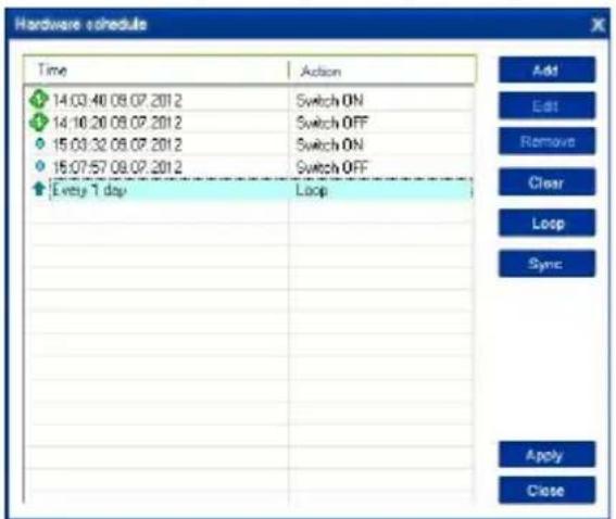
- The window Add entry will appear (see Figure #22 below). In the dialog box, specify the required time and the action
Figure #22

All brands and logos are registered trademarks of their respective owners
- To edit the record, select it and click the Edit button or just double click on the entry (see Figure #21 above). The same window will appear (see Figure #22 above)
- To remove the record, select it and click the Remove button (see Figure #21 above). You can select multiple entries using Ctrl and Shift keys. You can also remove all entries from the schedule by clicking the Clear button (see Figure #21 above)
- To set the period for periodic events (for example if you want to perform the same events every day) use the Loop button (see Figure #21 above) and specify the loop time period in the Edit loop period window (see Figure #23 below)
Figure #23
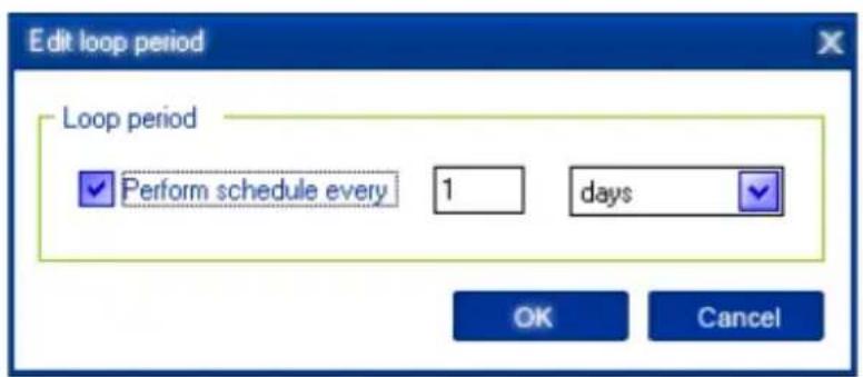
• After the schedule record has been created, click the Apply button (see Figure #21 above) to save the hardware timer schedule changes. In
case of incorrect entries, these will be highlighted and an error message will appear. Click the Apply button again after correcting all the errors - Use Sync button (see Figure #21 above) to synchronize device timer with PC clock. Note that after synchronization past entries will be removed from the schedule
HINT: Use the popup menu (see Figure #21 above) which can be activated by the right mouse button click over the table.
NOTE: The hardware schedule keeps running even when the device is powered off. However it is recommended not to power off the device for longer than 1 week, because the built-in battery might get discharged then. In this case the internal clock of the device would be reset and as result some schedule events would not be executed. Besides all the sockets would lose their previous status (they will be switched on). Leave the device switched on for one day to fully charge the battery.
7.2. Setting up software schedule
Using the Software schedule button available from the Settings window (see section 6.2 above) you can create the software timer schedule (see Figure #24 below).
NOTE: the software timer schedule will only be executed if the managing computer is on and the Power Manager is launched.
Figure #24

• To add a new task, click the Add button. The Add task window will appear (see Figure #25 below)
All brands and logos are registered trademarks of their respective owners
Figure #25

In the Add task window, check Switch ON time and/or Switch OFF time checkboxes and specify the time to switch the socked on and/or off. If you want the same event to be performed periodically, check Perform task every checkbox and specify the time interval. You can also add remarks about the task in the Comment field. To disable the task, uncheck the Enabled checkbox and to enable the task again, re-check the checkbox.
All brands and logos are registered trademarks of their respective owners
- To edit the task, select it (see Figure #24 above) and click the Edit button or just double click on the task. The Edit task window will appear (see Figure #26 below)
Figure #26

- To remove the task select it and click the Remove button (see Figure #24 above). You may select multiple tasks using Ctrl and Shift keys. You can also remove all tasks by clicking the Clear button
HINT: Use the popup menu which can be activated by the right mouse button click over the table (see Figure #24 above).
7.3. Setting up application events
Using the Application events window you can specify the socket events when a certain application is launched or closed down. You can also associate switching the sockets off or on with placement and removal of particular files in certain folders.
To use this feature push Application events button available from the Settings window (see section 6.2 above – Figure #20). You will get the following window (see Figure #27 below).
Figure #27

• To add a new program event, click the Add app button. The Add program event dialog will appear (see Figure #28 below)
All brands and logos are registered trademarks of their respective owners
Figure #28

Specify the application title and path to it using the Browse (...) button or typing it manually in the Title and Path name fields. If you use the Browse (...) button you can also select a shortcut to the application. In this case the application title and path name will be taken automatically via the shortcut if possible. After you have specified the application, check On run and/or On exit and choose the event (switch on or off).
NOTE: The On run event will take place when the first window of the selected application is opened. The On exit event will take place when the last window of the application is closed.
All brands and logos are registered trademarks of their respective owners
HINT: Your device is an advanced standby-killer. Using this feature you can for example switch your scanner on/off whenever Photoshop is started/closed.
- To add a new file event, click the Add folder button (see Figure #27 above). The Add file event window will appear (see Figure #29 below)
Figure #29

“Specify the path to the folder you would like to monitor using the Browse (...) button or typing it manually in the Path name field. Specify
All brands and logos are registered trademarks of their respective owners
the File name mask using wildcard characters: *, ?. Check then On placing and/or On removal checkboxes and select the event and delay.
NOTE: The On placing event will take place when the first file matching the specified file name mask is placed into the specified folder. The On removal event will take place when the last file matching the specified file name mask is removed from the specified folder.
HINT: Your device is an advanced standby-killer. Use the Add folder button to assign c:\system32\spool\printers folder to switch your printer on whenever you start printing and to switch it off again whenever you are ready with printing.
HINT: If you have several printers connected to the same computer, we suggest moving default spool directory of each printer to a separate location.
- To edit the event, select it and click the Edit button, or just double click on the event (see Figure #27 above). The Edit file event window will appear (see Figure #30 below)
Figure #30

- To remove the event, select it and click the Remove button (see Figure #27 above). You can select multiple events using Ctrl and Shift keys. You can also remove all events by clicking the Clear button
HINT: Use the popup menu which can be activated by the right mouse button click over the table.
8. Managing EG-PMS2-LAN via your own software
To let you switch the sockets from your own applications the following command line interface syntax is supported:
• pm.exe -[on | off] -device name -socket name
Examples:
- "C:\Program Files\Energenie\Power Manager\pm.exe" -on -My EnerGenie -Socket1
• "E:\Utils\PM3\pm.exe" -off -My EnerGenie -Table lamp - Execute pm.exe with -info key (pm.exe -info) to get the complete information about the status of the current devices.
For each of the connected devices the following information will then be provided and placed into Info.ini file in the Power Manager folder:
- DeviceName - the user specified device name
-
Socket#name, where # is replaced by a certain socket number - the user specified socket name
-
Socket#SwitchState, where # is replaced by a certain socket number - TRUE, when the socket is switched on, FALSE, when the socket is switched off
- Socket#VoltageState, where # is replaced by a certain socket number - TRUE, when voltage presence on the socket is detected, FALSE, when there is no voltage on the socket;
NOTE: Each use of this command line option totally overrides the data in Info.ini file.
NOTE: Power Manager should be active.
9. EG-PMS2-LAN SDK
For advanced users we supply the software development kit (SDK) to manage the device. Check the SDK manual in SDK folder on the supplied CD to get more information about it.
- Troubleshooting
| Problem | Solution |
| The rocker switch turns off. | The load connected to the device is too high, some of the devices connected to the EG-PMS2-LAN should be disconnected before the rocker switch can be turned on. |
| The switching command is not carried out, the rocker switch and indicators are not lit. | There is no power supply to the EG-PMS2-LAN. Please, make sure the EG-PMS2-LAN is connected to the power supply and the rocker switch is switched on. |
| The status of EG-PMS2-LAN in Power Manager does not become Connected | Try to ping the device (see section 6.1 above) |
| EG-PMS2-LAN is connected to local network (ping test is ok) but not responding. | Reset EG-PMS2-LAN by pressing the Reset button on the side control panel (see Figure #2 above) or switch it off and then on again using the Main rocker switch Z (see Figure #1 above). |
| Connection to EG-PMS2-LAN is lost. It seems something is wrong with its IP address. | Make sure EG-PMS2-LAN is connected to LAN and switched on. Launch Find EG-PMS2-LAN utility. You can also try to use IP config (C) button to let the device renew its IP address (see section 3.2 above) |
CERTIFICATE
of Conformity Low Voltage Directive 2006/95/EC
Registration No.: AN 50243877 0001
Report No.: 17014557 002

Holder:
GEMBIRD ELECTRONICS LTD. Flat. RM 2103, 21/F Office Tower Langham Place 8 Argyle Street Mongkok Hong Kong
Product:
Multiple Socket Outlets (Portable Socket-outlet with Surge Protection)
Identification:
EG-PMS2-LAN EG-10552
Serial No.: n.a.
Remark : Issued in conjunction with above 707 Rheinland license S1 50241875 0001.
This certificate of conformity is based on an evaluation of a sample of the above mentioned product. Technical Report and documentation are at the Licence Holder's disposal. This is to certify that the tested sample is in conformity with all revision of Annex I of Council Directive 2006/88/EC, in its latest amended version, referred to as the Low Voltage Directive. This certificate does not imply assessment of the series-production of the product and does not permit the use of a TUV Rheinland mark of conformity. The holder of the certificate is authorized to use this certificate in connection with the EC declaration of conformity according to Annex III of the Directive.

Date 21.12.2012
Certification Body

CE The CE marking may be used if all relevant and effective EC Directives are complied with. CE
| (ENG) Declaration of conformityThis product is tested and complies with the essential requirements of the laws of member states concerning EMC(2014/30/EU), RoHS (2011/65/EU). The CE declaration can be found underwww.gembird.eu |
| (DE) KonformitätserklärungDieses Produkt wurde getestet und stimmt mit den grundlegenden Anforderungen der Richtlinie EMC(2014/30/EU), RoHS (2011/65/EU) überein. Die Konformitätserklärung kann auf unserer Webseitewww.gembird.euheruntergeladen werden. |
| (ES) Declaración de conformidadEste producto está probado y cumple con los requisitos esenciales de las leyes de los estados miembros con respecto a EMC (2014/30 / UE), RoHS (2011/65 / UE). La declaración CE se puede encontrar enwww.gembird.eu |
| (CZ) Prohlášení o shoděTento produkt je testován a splňuje základní požadavky právních předpisů členských států týkajících se EMC (2014/30 / EU), RoHS (2011/65 / EU). Prohlášení CE naleznete nawww.gembird.eu |
| (FR/BE) Déclaration de conformitéLe produit est contrôlé et rempli les exigences des directives nationales et de la directive EMC(2014/30/EU), RoHS (2011/65/EU). La conformité CE a été démontrée et les déclarations correspondantes sont déposées chez le fabricant a:www.gembird.eu |
| (HR) Izjava o sukladnostiOvaj je proizvod testiran i udovoljava osnovnim zahtjevima zakona država članica u veziEMC-a (2014/30 / EU), RoHS (2011/65 / EU). Izjava CE se može naci podwww.gembird.eu |
| (IT) Dichiarazione di conformitàQuesto prodotto è testato ed è conforme ai requisiti essenziali delle leggi degli stati membri in materia di EMC (2014/30 / UE), RoHS (2011/65 / UE). La dichiarazione CE è disponibile all'indirizzowww.gembird.eu |
| (PT) Declaração de conformidadeEste produto foi testado e está em conformidade com os requisitos essenciais das leis dos estados membros sobre EMC (2014/30 / EU), RoHS (2011/65 / EU). A declaração CE pode ser encontrada emwww.gembird.eu |
| (PL) Deklaracja zgodnościTen produkt został przetestowany i jest zgodny z zasadniczymi wymaganiami prawnymi państw członkowskich dotyczącymi EMC (2014/30 / UE), RoHS (2011/65 / UE). Deklaracja CE znajduje się na stroniewww.gembird.eu |
| (RO) Declaratie de conformitateAcest produs este testat și respectă cerințele esențiale ale legislațiilor statelor membre privind EMC (2014/30 / UE), RoHS (2011/65 / UE). Declarația CE se găsește pewww.gembird.eu |
| (SK) Vyhlásenie o zhodeTento produkt je testovaný a splňa základné požiadavky právnych predpisov členských štátov týkajúcich sa EMC (2014/30 / EÚ), RoHS (2011/65 / EÚ). Vyhlásenie CE nájdete na stránkewww.gembird.eu |
| (SL) Izjava o skladnostiTa izdelek je preizkušen in ustreza bistvenim zahtevam zakonov držav članic o EMC (2014/30 / EU), RoHS (2011/65 / EU). Izjava CE je na voljo podwww.gembird.eu |
| (GR) Δήλωση συμμόρφωσηςΑυτό το προϊόν έχει ελεγχθεί και συμμορφώνεται με τις βασικές απαιτήσεις των νομοθεσιών των κρατών μελών όσον αφορά την Ευρωπαϊκή οδηγία g EMC (2014/30 / EU), RoHS (2011/65 / EU).Η δήλωση CE μπορεί να βρεθεί στην διεύθυνσηwww.gembird.eu |
| (ENG) Waste disposal:Do not deposit this equipment with the household waste. Improper disposal can harm both the environment and human health. For Information about waste collection facilities for used electrical and electronic devices, please contact your city council or an authorized company for the disposal of electrical and electronic equipment. |
| (DE) Entsorgungshinweise:Werfen Sie dieses Gerät nicht in den Hausmüll. Unsachgemäße Entsorgung kann sowohl der Umwelt als auch der menschlichen Gesundheit schaden.Informationen zu Sammelstellen für Altgeräte erhalten Sie bei Ihrer Stadtverwaltung oder einer autorisierten Stelle für die Entsorgung von Elektro-und Elektronikgeräten. |
| (ES) Deposito de basura:No deposite este equipo con la basura doméstica. La eliminación inadecuada puede dañar tanto el medio ambiente como la salud humana. Para obtener información sobre las instalaciones de recolección de desechos para dispositivos eléctricos y electrónicos usados, comuníquese con su ayuntamiento o una empresa autorizada para la eliminación de equipos eléctricos y electrónicos. |
| (CZ) Nakládání s odpady:Toto zařízení nevkládejte do domovního odpadu. Nesprávná likvidace může poškodit životní prostředí i lidské zdraví. Informace o zařízení pro sběr odpadu použitých elektrických zařízení získáte u městské rady nebo autorizované společnosti o likvidaci elektrických zařízení. |
| (FR/BE) Traitement des déchets:Ne jetez pas cet appareil dans les déchets domestiques. Un traitement inapproprié peut être dommageable à l'environnement et à la santé humain. Vous trouvez des informations sur les centres de rassemblement des appareils vieux chez l'administration municipale ou chez un centre autorisé pour le traitement des appareils électriques ou électroniques. |
| (HR) Odlaganje smeća:Ovu opremu ne odlazite zajedno s kućnim otpadom. Nepravilno odlaganje može naštetiti okolišu i ljudskom zdravlju. Za informacije o objektima za prikupljanje otpada za rabljene električne i elektroničke uređaje obratite se gradskom vijeću ili ovlaštenom društvu za odlaganje električne i elektroničke opreme. |
| (IT) Smaltimento dei rifiuti:Non depositare questa apparecchiatura con i rifiuti domestici. Lo smaltimento improprio può danneggiare sia l'ambiente che la salute umana. Per informazioni sulle strutture di raccolta dei rifiuti per i dispositivi elettrici ed elettronici usati, contattare il comune o una società autorizzata per lo smaltimento delle apparecchiature elettriche ed elettroniche. |
| (PT) Depósito de lixo:Não deposite este equipamento no lixo doméstico. O descarte inadequado pode prejudicar o meio ambiente e a saúde humana. Para obter informações sobre instalações de coleta de lixo para dispositivos elétricos e eletrônicos usados, entre em contato com o conselho da cidade ou uma empresa autorizada para o descarte de equipamentos elétricos e eletrônicos. |
| (PL) Utylizacja odpadów:Nie należy deponować tego sprzętu razem z odpadami domowymi. Niewłaściwa utylizacja može zaszkodzić zarówno środowisku, jak i zdrowiu ludzkiemu.Aby uzyskać informacje na temat urządzeń do zbierania zużytych urządzeń elektrycznych i elektronicznych, należy skontaktować się z radą miasta lub upoważnioną firmą w celu usunięcia sprzętu elektrycznego i elektronicznego. |
| (RO) Eliminarea deşeurilor:Nu depunęti acest echipament cu deşeurile menajere. Eliminarea necorespunzátoare poate dăuna atât mediului, cât și sănătății umane. Pentru informații despre instalațiile de colectare a deşeurilor pentru dispozitive electrice și electronice folosite, vă rugăm să contactați consiliul municipal sau o companie autorizată pentru eliminarea echipamentelor electrice și electronice. |
| (SK) Likvidácia odpadu:Toto zariadenie nevkladajte do domového odpadu. Nesprávna likvidácia može poškodit životné prostredie a l'udské zdravie. Informácie o zariadeniach na zber použitého odpadu z elektrických a elektronicých zariadení získate od mestského zastupitel'stva alebo od autorizovanej spoločnosti o likvidácii elektrických a elektronických zariadení. |
| (SL) Odlaganje odpadkov:Te opreme ne odlagajte skupaj z gospodinjskimi odpadki. Nepravilno odstranjevanje lahko škoduje okolju in zdravju ljudi. Za informacije o napravah za zbiranje odpadnih električnih in elektronskih naprav se obrnite na mestni svet ali pooblaščeno podjetje za odstranjevanje električne in elektronske opreme. |
| (GR) Διαχείριση απορριμάτων:Μην καταθέτετε αυτόν τον εξοπλισμό στα οικιακά απορρίμματα. Η ακατάλληλη απόρριψη μπορεί να βλάψει τόσο το περιβάλλον όσο και την ανθρώπινη υγεία.Για πληροφορίες σχετικά με τις εγκαταστάσεις συλλογής απορριμμάτων για χρησιμοποιημένες ηλεκτρικές και ηλεκτρονικές συσκευές, επικοινωνήστε με το δημοτικό συμβούλιο ή μια εξουσιοδοτημένη εταιρεία για τη διάθεση ηλεκτρικών και |
(ENG) WARRANTY CONDITIONS
The receipt must clearly list the date of purchase and the part number, in addition it should be printed. Keep the receipt for the entire warranty period since it is required for all warranty claims. During the warranty period the defective items will be credited, repaired or replaced at the manufacturer's expense. Work carried out under the warranty neither extends the warranty period nor starts a new warranty period. The manufacturer reserves the right to void any warranty claim for damages or defects due to misuse, abuse or external impact (falling down, impact, ingress of water, dust, contamination or break). Wearing parts (e.g. rechargeable batteries) are excluded from the warranty. Upon receipt of the RMA goods, Gembird Europe B.V. reserves the right to choose between replacement of defective goods or issuing a credit note. The credit note amount will always be calculated on the basis of the current market value of the defective products. Gembird Europe B.V. Wittevrouwen 56, 1358CD Almere, The Netherlands
www.gembird.nl/service support@gmb.nl
(DE) GARANTIE BEDINGUNGEN
All brands and logos are registered trademarks of their respective owners
- Introduction
- Features
- Specifications
- Hardware requirements
- Package contents
- Indicators and controls of the EG-PMS2-LAN
- Indicators
- Installation
- Getting started
- Preparing LAN configuration of EG-PMS2-LAN
- Power Manager installation
- IP configuration
- The web server
- Web-server login page
- EnerGenie page
- Socket page
- Socket Name settings page
- LAN settings page
- Device settings page
- Web-server logout
- EnerGenie.com device interface
- Logging in
- Device management page
- Power Manager software
- Finding EG-PMS2-LAN
- Figure #15
- Managing EG-PMS2-LAN
- Power Manager core features
- Setting up the hardware schedule
- Setting up software schedule
- Setting up application events
- Managing EG-PMS2-LAN via your own software
- EG-PMS2-LAN SDK
- CERTIFICATE
- Holder:
- Product:
- Identification:
- (ENG) WARRANTY CONDITIONS
- (DE) GARANTIE BEDINGUNGEN
Brand : EnerGenie
Model : EG-PMS2-LAN
Category : Socket