IDS Display - Display screen SIMRAD - Free user manual and instructions
Find the device manual for free IDS Display SIMRAD in PDF.


| Product Type | Marine Multifunction Display |
| Brand | Simrad |
| Model | IDS Display |
| Screen Size | 12.1 inches (typical) |
| Display Resolution | 1280 x 800 pixels |
| Display Technology | LED-backlit TFT LCD |
| Touchscreen | Optical bonding with anti-reflective coating |
| Waterproof Rating | IPX6 and IPX7 (front panel) |
| Operating Temperature | -15°C to +55°C |
| Power Supply | 10-32 V DC |
| Power Consumption | Typically 20 W (without backlight dimming) |
| Dimensions (WxHxD) | 330 x 215 x 65 mm |
| Weight | 2.4 kg |
| Mounting | Flush or bracket mount |
| Connectivity | NMEA 2000, NMEA 0183, Ethernet, USB, Video input |
| Supported Sonar | CHIRP, SideScan, DownScan (via optional modules) |
| Supported Radar | Broadband 3G/4G (via optional modules) |
| Charts | C-MAP, Navionics, or similar (optional) |
| Processor | Dual-core ARM Cortex-A9 |
| Operating System | Simrad proprietary software (Linux-based) |
| Maintenance | Clean with soft, damp cloth; avoid solvents |
| Safety | Overvoltage protection, reverse polarity protection |
| Spare Parts Availability | Contact Simrad dealer for replacement parts |
| Warranty | 2 years (subject to terms) |
Frequently Asked Questions - IDS Display SIMRAD
User questions about IDS Display SIMRAD
0 question about this device. Answer the ones you know or ask your own.
Ask a new question about this device
Download the instructions for your Display screen in PDF format for free! Find your manual IDS Display - SIMRAD and take your electronic device back in hand. On this page are published all the documents necessary for the use of your device. IDS Display by SIMRAD.
USER MANUAL IDS Display SIMRAD
As Navico is continuously improving this product, we retain the right to make changes to the product at any time which may not be reflected in this version of the manual. Please contact your nearest distributor if you require any further assistance.
It is the owner's sole responsibility to install and use the instrument and transducers in a manner that will not cause accidents, personal injury or property damage. The user of this product is solely responsible for observing safe boating practices.
NAVICO HOLDING AS AND ITS SUBSIDIARIES, BRANCHES AND AFFILIATES DISCLAIM ALL LIABILITY FOR ANY USE OF THIS PRODUCT IN A WAY THAT MAY CAUSE ACCIDENTS, DAMAGE OR THAT MAY VIOLATE THE LAW.
Governing Language
This statement, any instruction manuals, user guides and other information relating to the product (Documentation) may be translated to, or has been translated from, another language (Translation). In the event of any conflict between any Translation of the Documentation, the English language version of the Documentation will be the official version of the Documentation. This manual represents the product as at the time of printing. Navico Holding AS and its subsidiaries, branches and affiliates reserve the right to make changes to specifications without notice.
Copyright
Copyright © 2019 Navico Holding AS.
Warranty
The warranty card is supplied as a separate document. In case of any queries, refer to the brand web site of your display or system:
www.lowrance.com
www.simrad-yachting.com
www.bandg.com
Compliance Statements
Europe
Navico declare under our sole responsibility that the product conforms with the requirements of:
• Integration hub: CE under RED 2014/53/EU
• Display module: CE under EMC Directive 2014/30/EU
The relevant declaration of conformity is available in the product's section at the following website:
www.lowrance.com
www.simrad-yachting.com
www.bandg.com
Countries of intended use in the EU
AT - Austria LI - Liechtenstein
BE - Belgium LT - Lithuania
BG - Bulgaria LU - Luxembourg
CY - Cyprus MT - Malta
CZ - Czech Republic NL - Netherlands
DK - Denmark NO - Norway
EE - Estonia PL - Poland
FI - Finland PT - Portugal
FR - France RO - Romania
DE - Germany SK - Slovak Republic
GR - Greece SI - Slovenia
HU - Hungary ES - Spain
IS - Iceland SE - Sweden
IE - Ireland CH - Switzerland
IT - Italy TR - Turkey
LV - Latvia UK - United Kingdom
United States of America
Navico declare under our sole responsibility that the product conforms with the requirements of:
- Part 15 of the FCC Rules. Operation is subject to the following two conditions: (1) this device may not cause harmful interference, and (2) this device must accept any interference received, including interference that may cause undesired operation.
Warning: The user is cautioned that any changes or modifications not expressly approved by the party responsible for compliance could void the user's authority to operate the equipment.
Note: This equipment generates, uses and can radiate radio frequency energy and, if not installed and used in accordance with the instructions, may cause harmful interference to radio communications. However, there is no guarantee that the interference will not occur in a particular installation. If this equipment does cause harmful interference to radio or television reception, which can be determined by turning the equipment off and on, the user is encouraged to try to correct the interference by one or more of the following measures:
• Reorient or relocate the receiving antenna
- Increase the separation between the equipment and receiver
- Connect the equipment into an outlet on a circuit different from that of the receiver
- Consult the dealer or an experienced technician for help
Industry Canada
This device complies with Industry Canada's license-exempt RSSs. Operation is subject to the following two conditions: (1) This device may not cause interference; and (2) This device must accept any interference, including interference that may cause undesired operation of the device.
Industry Canada Statement: Under Industry Canada regulations, this radio transmitter may only operate using an antenna of a type and maximum (or lesser) gain approved for the transmitter by Industry Canada. To reduce potential radio interference to other users, the antenna type and its gain should be so chosen that the equivalent isotropically radiated power (e.i.r.p.) is not more than that necessary for successful communication.
Australia and New Zealand
Navico declare under our sole responsibility that the product conforms with the requirements of:
• Level 2 devices of the Radiocommunications (Electromagnetic Compatibility) standard 2017
• Radiocommunications (Short Range Devices) Standards 2014
Trademarks
- Navico® is a registered trademark of Navico Holding AS.
- Lowrance® is a registered trademark of Navico Holding AS.
- Simrad® is used by license from Kongsberg.
- B&G is a registered trademark of Navico Holding AS.
Contents
3 Preface
7 Introduction
7 About this manual
7 Information Display system
8 Branding options
9 Standard glass
10 Smart Display module sizes (not including any glass overhang)
11 Custom glass
11 Maximum glass size
11 Minimum glass sizes
13 Maximum glass edge
14 Smart Display module sizes (not including any glass overhang)
15 Information Display modules
15 Mounting guidelines
16 Mounting methods
1
Introduction
About this manual
This document is used to aid the boat builder in designing the Information Display system. The document covers a range of standard Information Display systems and also guidelines for creating customized Information Display dashes.
Important text that requires special attention from the reader is emphasized as follows:
→ Note: Used to draw the reader's attention to a comment or some important information.
Warning: Used when it is necessary to warn personnel that they should proceed carefully to prevent risk of injury and/or damage to equipment/personnel.
Information Display system
The Information Display system consists of:
- Bonded glass smart display (Information Display) Single or multiple Smart Displays bonded to a single glass.
- Integration Hub The hub allows for connecting various vessel equipment to the Information Display system.

A Bonded glass smart display
B Integration hub
C Accessories and optional equipment
This document covers the range of standard displays and also describes guidelines for customized setup. The glass is not only a lens for the display(s) but also makes up the dashboard surface.
The standard setup consists of a single or dual screen configuration. Both 9" and 12" screens are available.
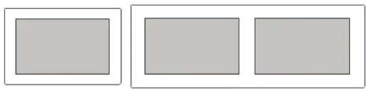
Custom display setups can consist of various sizes and shapes to suit the vessel dash.

Branding options
Available brands are:
SIMRAD LOWRANCE B&G
| Brand logo | Width Height | |||
| mm inches | mm inches | |||
| Simrad 35.5 1.40 | 8 0.31Lowrance 57.0 2.24 | |||
| B&G 42.0 1.65 | ||||
The logo text is white color, and will be placed on the top-center of the display.

2
Standard glass
Standard rectangular glass is available in two sizes for single and dual displays. The glass thickness is 3.2 mm (0.12").
| Configuration | A B C D | |||||||
| mm inch mm inch mm inch mm inch | ||||||||
| Single 9" 252 | 9.92 | 165 | 6.50 | 3.0 | 0.12 | N/A | ||
| Single 12" | 322 | 12 | 68 | 220 | 8.66 | |||
| Dual 9" | 548.5 | 21.58 | 199.5 | 7.83 | 63.5 | |||
| Dual 12" | 686 | 27.01 | 254.5 | 10.02 | 68.9 | |||
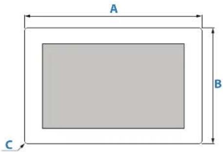

A Width
B Height
C Corner radius
D Gap between LCD visual/active area
→ Note: For standard glass mounting, we recommend the Dash Pocket-Frame mounting option. Refer to "Mounting methods" on page 16.
Smart Display module sizes (not including any glass overhang)
Smart Display modules not including any glass overhang have the following dimensions:
| Size | A B C | |||||
| mm inch | mm inch | mm inch | ||||
| 9" 236.5 9 | 31 149 | 5.91 | 50.5 1.99 | |||
| 12" 305 12 | 01 204 | 8.03 | 58.0 2.28 | |||


A Width
B Height
C Total depth without glass (the glass is 3.2 mm (0.12") thick)
3
Custom glass
Custom glass can be rectangular or different shapes to suit the vessel dash.
Advantage with customized glass:
- Ability to specify more than one LCD display
• Shape can be rectangular or custom
• Better dash appearance
• Different look compared to other boat builders
→ Note: Customized glass designs will be subject to a non-recurring engineering fee (NRE).
Maximum glass size
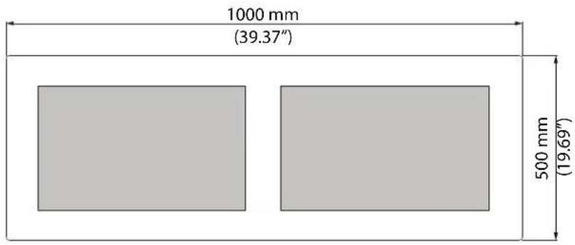
Minimum glass sizes
Single display pocket and bracket mounting
| Size | A B C | |||||
| mm inch | mm inch mm inch | |||||
| 9" 238 9.37 | 151 | 5.95 20 | 0.79 | |||
| 12" | 308 | 12.13 | 206 | 8.11 23 0.91 | ||
| Size | D | E | F | |||
| mm | inch | mm | inch | mm | inch | |
| 9" | 23 | 0.91 16 | 0.63 | 0 - 10 | 0 - 0.39 | |
| 12" 23 | 0.91 20 | 0.79 | ||||

A Width
B Height
C Distance between glass side edge and active area
D Distance between glass bottom edge and active area
E Distance between glass top edge and active area
F Corner radius, min - max
Single display dual lock mounting
For mounting by adhering from rear glass edges (assumes 8 mm glass width for adhering). Corner radius 0 mm - 17 mm.
| Size | A B C | |||||
| mm inch | mm inch mm inch | |||||
| 9" 252 9.9 | 2 165 | 6.50 27 | 1.06 | |||
| 12" 322 | 12.68 | 220 | 8.66 | 30 | 1.18 | |
| Size | DEF | |||||
| mm inch | mm inch mm inch | |||||
| 9" 30 | 1.18 | 23 | 0.91 | 0 - 17 | 0 - 0.67 | |
| 12" 30 | 1.18 | 27 | 1.06 | |||

A Width
B Height
C Distance between glass side edge and active area
D Distance between glass bottom edge and active area
E Distance between glass top edge and active area
F Corner radius, min - max
Dual display pocket and bracket mounting
| Size | A B C | |||||
| mm inch | mm inch | mm inch | ||||
| 9" 490 19 | 29 | 165 | 6.50 | 0 - 5 0 - 0.2 | ||
| 12" 629 24 | 76 | 220 | 8.67 | |||
| Size | DEFG | |||||||
| mm | inch | mm | inch | mm | inch | mm | inch | |
| 9" | 39 | 1.54 | 27 | 1.06 | 30 | 1.18 | 23 | 0.91 |
| 12" | 46 | 1.82 | 30 | 1.18 | 30 | 1.18 | 27 | 1.06 |
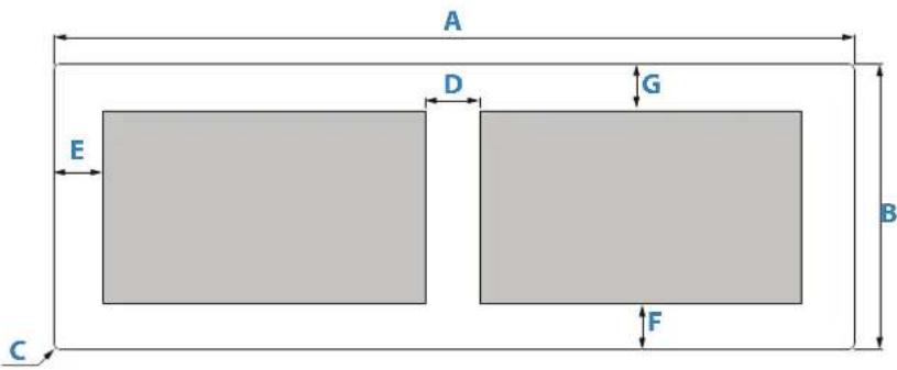
A Width
B Height
C Corner radius
D Gap between LCD visual/active area
Maximum glass edge
The maximum free glass distance (from the display housing edge to the glass edge) shall be 50 mm in all sizes.

Smart Display module sizes (not including any glass overhang)
Smart Display modules not including any glass overhang have the following dimensions:
| Size | A B C | |||||
| mm inch | mm inch | mm inch | ||||
| 9" 236.5 9 | 31 149 | 5.91 | 50.5 1.99 | |||
| 12" 305 12 | 01 204 | 8.03 | 58.0 2.28 | |||


A Module width
B Module height
C Module depth
4
Information Display modules
Mounting guidelines
General
Enclosures should be dry and well ventilated. In small enclosures, it may be required to fit forced cooling. Leave sufficient clearance to connect all relevant cables.
Dash flatness
The surface the Information Display attaches to must be flat, with no more than 1 mm (0.04") deviation from a theoretical flat plane over a distance of 500 mm (20"). This is to avoid the glass and LCD's being distorted when installed in the vessel.

Thermal considerations
→ Note: White materials will be around 8°C (14°F) cooler than black materials in direct sunlight.
⚠ Warning: Inadequate ventilation and subsequent overheating of the unit may cause unreliable operation and reduced service life. Exposing the unit to conditions that exceeds the specifications could invalidate your warranty.
- Ensure adequate separation between products that generate heat
- Ensure reasonable airspace around the Information Display, minimum 150 mm (5.91") at rear (E) and 75 mm (2.95") at top/bottom/sides (D) is recommended.
- If the Information Display is mounted in an angle (A) of less than 45° , ensure that the air temperature inside the enclosure does not exceed 35° C ( 95° F) with no air flow, or 45° C ( 113° F) with forced airflow (minimum air velocity across the back of the unit 1 m/s (3.3 ftps)).
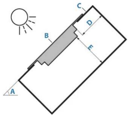
A Installation angle
B Information Display
C Dashboard enclosure
D 75 mm (2.95") minimum free space to top, bottom and sides
E 150 mm (5.91") minimum free space at the rear
Sun cover
It is recommended the Information Display is protected from the sun when the unit is not in use. Sun covers are not supplied by Navico.
Dash seal
Each display has a foam seal (A). The foam seal prevents water ingression.
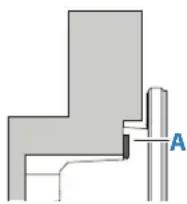
No additional seal is required for bracket, dash pocket-frame and dual lock mounting.
Mounting methods
Pocket versus exposed glass installation
There are two options to install the glass. Both of them can be used with all three mounting methods.
Pocket installation
The glass (B) is recessed into the dashboard (A).

Advantages:
• Lower risk of glass being damaged
Disadvantages:
• Water/ice accumulation risk in pocket
• Dust/dirt accumulation risk in pocket
• Potential fit/tolerances issues
Exposed glass edges
The glass (B) is placed over dashboard (A).

Advantages:
• No water/ice accumulation risk.
• No dust/dirt accumulation risk.
- No fit/tolerances issues.
Disadvantages:
• There is a risk of cracking the entire glass due to an impact on corners or edges.
Dash bracket mount
Advantages:
- Allows use of the smallest glass size
• Friendly for service - easy to remove - Does not require adhesive to seal (foam seal included)
• No stress is being applied to the glass, product is held by the display module plastic housing
Disadvantages:
- Requires access to the inside of dash during assembly
• Each bracket has 6 separate components
Clamping force must only be applied to the Information Display enclosure. After installation, there should be a small gap (F) between the dash and the Information Display glass.
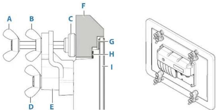
A Wing screw to fix product
B Wing nut to lock and prevent from loosening
C Bracket foot
D Wing screw to fix the bracket on the Smart Display module
E Bracket body
F Boat bulkhead/dash
G Gap between Information Display glass and dash
H Foam seal
1 Information Display glass and Smart Display module(s)
Mounting cutout size
| Size | A | B | ||
| mm inch | mm inch | |||
| 9" 224.7 8 | 84 | 137.2 5.40 | ||
| 12" 301.2 1 | 11.85 | 202.7 7.98 | ||

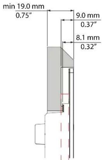
9" display dash steps

12" display dash steps
Dash pocket-frame mounting
Advantages:
- Allows use of the smallest glass size
• Friendly for service - easy to remove - Does not require adhesive to seal (foam seal included)
- No stress is being applied to the glass - product is held by plastic housing. Disadvantages:
- Requires access to the inside of dash to assemble
- Boat builder has to machine several pockets in a dash
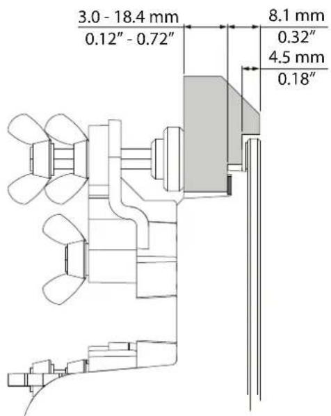
Clamping force must only be applied to the Information Display enclosure. After installation, there should be a small gap (D) between the dash and the Information Display glass.

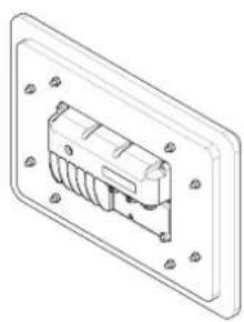
A M5 threaded rod
B M5 nut/locking nut
C Boat bulkhead/dash
D Gap between Information Display glass and dash
E Foam seal
F Information Display glass and Smart Display module(s)
Mounting cutout size
| Size | A | B | ||
| mm inch | mm inch | |||
| 9" | 176.7 | 6.96 108.7 | 4.28 | |
| 12" | ||||

9" display dash steps

12" display dash steps

Dual-Lock
Advantages:
- Does not require free space in the dash cavity corners or edge for fastening
- Does not require adhesive to seal (foam seal included)
• Friendly for service, not hard to remove
Disadvantages:
- Needs free space in the glass edges to attach the Dual-Lock strips. Smallest glass cannot be used
- Stress is being applied to the glass, product is attached by the glass, not the display module housing

A Dual-Lock strips
B Boat bulkhead/dash
C Gap between Information Display glass and dash
D Foam seal
E Information Display glass and Smart Display module(s)
Mounting cutout size
| Size | A | B | ||
| mm inch mm inch | ||||
| 9" 252.7 9 | 95 | 138.2 5.44 | ||
| 12" 294.6 1 | 11.60 | 193.4 7.61 | ||

Required Dual-Lock strips
| Configuration | Number of strips SJ3560 / SJ3562 | Width of the strips Length of the strips | |||
| mm inches mm inches | |||||
| Single 9" | 2/2 | 19 3/4 | 140 5.5 | ||
| Single 12" 165 | 6.5 | ||||
| Dual 9" | 3/3 | 140 5.5 | |||
| Dual 12" 219 | 8.6 | ||||
→ Note: The Information Display will need to have enough glass overhang to place the Dual-Lock strips. Standard single 9" and Standard single 12" do not meet with this requirement.
9" display dash steps
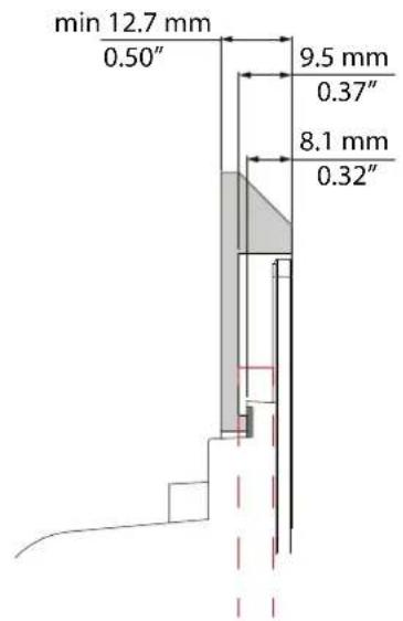
12" display dash steps

LOWRANCE
SIMRAD
B&G
- GOVERNING LANGUAGE
- COPYRIGHT
- WARRANTY
- COMPLIANCE STATEMENTS
- EUROPE
- COUNTRIES OF INTENDED USE IN THE EU
- UNITED STATES OF AMERICA
- INDUSTRY CANADA
- AUSTRALIA AND NEW ZEALAND
- TRADEMARKS
- CONTENTS
- 3 PREFACE
- 7 INTRODUCTION
- 9 STANDARD GLASS
- 11 CUSTOM GLASS
- 15 INFORMATION DISPLAY MODULES
- 1
- INTRODUCTION
- ABOUT THIS MANUAL
- INFORMATION DISPLAY SYSTEM
- BRANDING OPTIONS
- SIMRAD LOWRANCE B&G
- 2
- STANDARD GLASS
- SMART DISPLAY MODULE SIZES (NOT INCLUDING ANY GLASS OVERHANG)
- 3
- CUSTOM GLASS
- ADVANTAGE WITH CUSTOMIZED GLASS
- MINIMUM GLASS SIZES
- SINGLE DISPLAY DUAL LOCK MOUNTING
- MAXIMUM GLASS EDGE
- 4
- INFORMATION DISPLAY MODULES
- MOUNTING GUIDELINES
- GENERAL
- DASH FLATNESS
- THERMAL CONSIDERATIONS
- SUN COVER
- DASH SEAL
- MOUNTING METHODS
- POCKET VERSUS EXPOSED GLASS INSTALLATION
- POCKET INSTALLATION
- EXPOSED GLASS EDGES
- DASH BRACKET MOUNT
- DASH POCKET-FRAME MOUNTING
- DUAL-LOCK
Brand : SIMRAD
Model : IDS Display
Category : Display screen