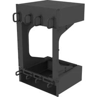
DIRLC9606RB1 - Ventilation system Panduit - Free user manual and instructions
Find the device manual for free DIRLC9606RB1 Panduit in PDF.


| Type of Product | Surface Raceway |
| Brand | Panduit |
| Model | DIRLC9606RB1 |
| Color | Black |
| Material | PVC (Polyvinyl Chloride) |
| Dimensions (L x W x D) | 6 ft (1.83 m) x 2.4 in (61 mm) x 1.2 in (30 mm) |
| Weight | 1.2 lb (0.54 kg) |
| Mounting Type | Screw or Adhesive (double-sided tape included) |
| Included Components | Raceway base, snap-on cover, mounting screws, adhesive tape, end caps |
| Application | Indoor cable management for data, voice, and AV cables |
| Compatibility | Standard Panduit fittings, joints, and bends |
| Operating Temperature | 32°F to 140°F (0°C to 60°C) |
| Flammability Rating | UL 94 V-0 |
| Standards | RoHS compliant, REACH compliant |
| Features | Snap-on cover for easy cable access, smooth edges to protect cables, multiple cable capacity |
| Installation | Cut table with standard utility knife, miter box recommended |
| Capacity | Up to 6 Cat6 cables or equivalent |
| Cleaning | Wipe with damp cloth, do not use abrasive cleaners |
| Storage | Keep in dry place away from direct sunlight |
| Warranty | 5 years against manufacturing defects |
Frequently Asked Questions - DIRLC9606RB1 Panduit
User questions about DIRLC9606RB1 Panduit
0 question about this device. Answer the ones you know or ask your own.
Ask a new question about this device
Download the instructions for your Ventilation system in PDF format for free! Find your manual DIRLC9606RB1 - Panduit and take your electronic device back in hand. On this page are published all the documents necessary for the use of your device. DIRLC9606RB1 by Panduit.
USER MANUAL DIRLC9606RB1 Panduit
NOTE: This Duct System requires the Switch to be rotated 90° from its standard orientation

Rear of Cabinet (Hot Aisle)
Hardware Included
| M4 x 0.7 x 12mm PanHead Phillips ScrewW/Split Lock Washer8x |

M6 x 1
Cage Nut
25x

M6 x 1 x 15mm
Round Head Screw
25x

12-24 Bonding
Cage Nut Kit
4 of each


M3x0.5 x 6mm
Flat Head Screw
6x

M6 Serrated FLANGE
Hex Nut
16x

1RU Cable Manager (4x) CMDRH1

2RU Cable Manager (4x) CMDRH2

natural_image
Pure technical line drawing of a U-shaped mechanical component (no text or symbols)For Technical Support: www.panduit.com/resources/install_maintain.asp
Component Guide

natural_image
Technical line drawing of a rectangular metal enclosure with mounting holes and frame railings (no text or symbols)Inlet Duct

natural_image
Line drawing of a rectangular electronic enclosure with mounting holes and mounting brackets (no text or symbols)Exhaust Duct
natural_image
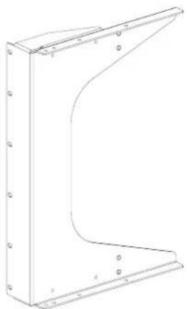
Technical line drawing of a metal bracket with mounting holes and a curved cutout (no text or symbols)Vertical Mounting Bracket (2x)


natural_image
Technical line drawing of a mechanical bracket with mounting holes and mounting holes (no text or symbols)Adjustable Bracket Left Top (LT) & Right Bottom (RB) (2x)

natural_image
Technical line drawing of a mechanical bracket with mounting holes and mounting holes (no text or symbols)Adjustable Bracket Right Top (RT) & Left Bottom (LB) (2x)
1.0 Preparation
1.1 17RU Open Space Required
- Installation of the Switch, Bottom Inlet Duct, and Top Exhaust Duct requires 17RU. This space must be open prior to Switch Installation (Figure 1).
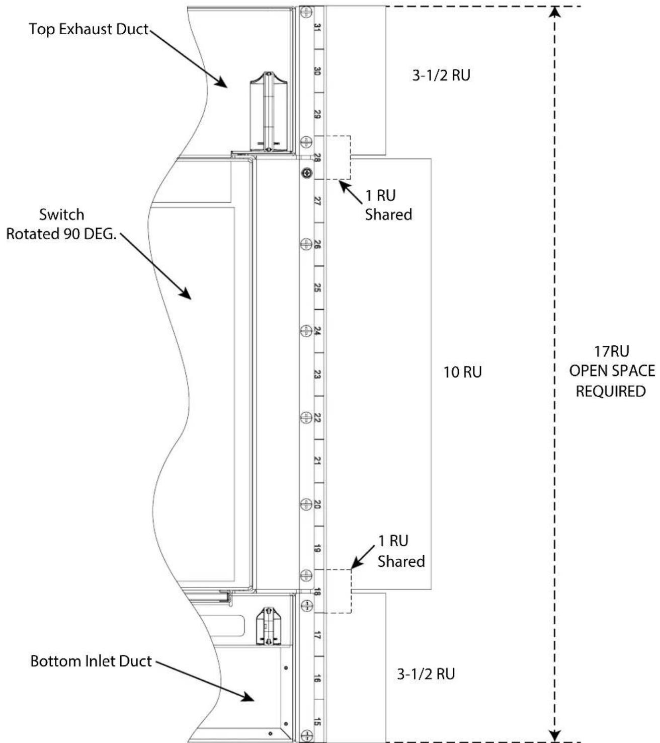
Figure 1
For Technical Support: www.panduit.com/resources/install_maintain.asp
2.0 Chassis Installation
2.1 Remove Mounting Ears
- Shown below
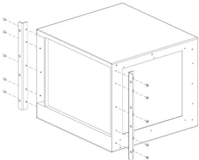
natural_image
Technical line drawing of a rectangular enclosure with vertical supports and mounting holes (no text or symbols)2.2 Vertical Mounting Bracket Installation
- Rotate Cisco 9606R 90 degrees counterclockwise. Fan Tray should be at top (Figure 2).
- Use M4 x 12mm (qty. 8) Pan Head Screws and (qty. 8) M4 Lock Washers for attaching Vertical Mounting Brackets (Figure 3).

Figure 2

natural_image
Technical line drawing of a mechanical housing or enclosure with mounting holes and structural ribs (no text or symbols)Figure 3
2.3 Optional Filter Bracket Installation
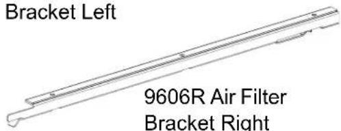
- Use M3 x 6mm (qty. 6) Flat Head Screws for attaching 9606R Air Filter Brackets (Figure 4).

Note: Filter Brackets do not need to be installed if NEBS-Compliant Air Filter will not be utilized
Figure 4
* Additional NEBS-Compliant information can be found at
www.cisco.com
(Cisco Catalyst 9600 Series Switches Hardware Installation Guide)
2.4 Cage Nut Installation
• Install (qty. 4) Bonding Cage Nuts Labeled A.
• Install (qty.16) M6 Cage Nuts In Locations (Figure 5).

Figure 5
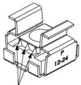
The four #12-24 Bonding Cage Nuts must be installed as shown below labeled A. Note: The Bonding Cage Nuts have 3 serrations on either side.
2.5 Vertical Mount Chassis Installation into Rack
- Note: Cisco Switch must rotate 90 degrees counterclockwise for installation. The Fan Tray will be at the top of the assembly.
- Bottom hole of Vertical Mounting Bracket installs into top hole of RU (Figures 6 & 7).
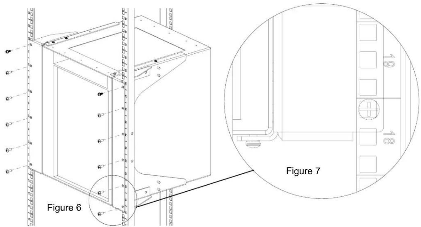
2.6 Extension Arm Installation
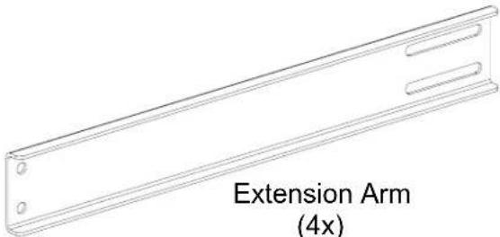
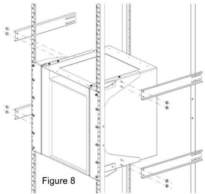
• Using the M6 Nuts provided, mount the Extension Arms to the Vertical Mounting Bracket (Figure 8).
• Note: DO NOT fully tighten Nuts at this point
natural_image
Technical line drawing of a cabinet frame structure with mounting brackets and structural details (no text or symbols)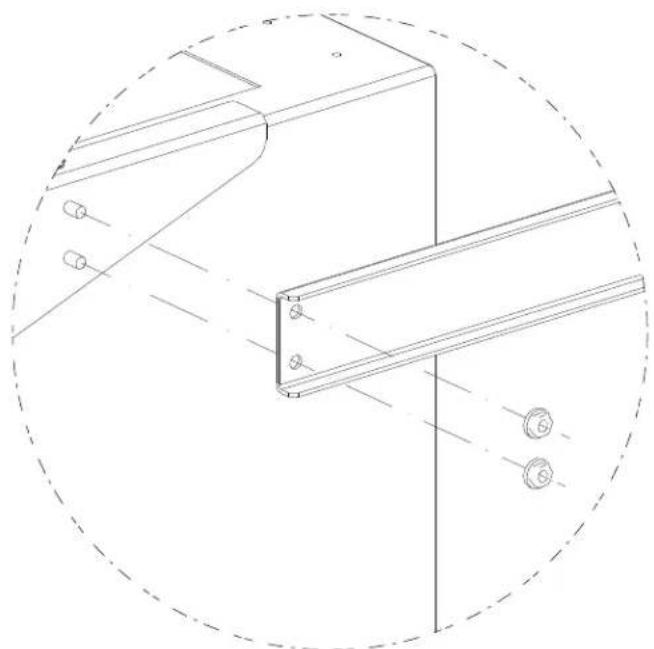
natural_image
Technical line drawing of a structural bracket with mounting holes and a circular boundary (no text or symbols)For Technical Support: www.panduit.com/resources/install_maintain.asp
2.7 Adjustable Bracket Installation
- Identify the two different Adjustable brackets. One is used for the top right and bottom left locations (Figures 9 & 9A). The other is used for the bottom right and top left positions (Figures 10 & 10A).
• Using the M6 Nuts provided, mount the Adjustable Brackets to the Extension Arms (Figure 11). - The mounting location of the top slot of the Adjustable Bracket is in the same location of the Chassis Vertical Mounting Bracket (Figure 11).
- Secure the Brackets in place. Also, TIGHTEN all the M6 Nuts to the Extension Arms.

3.0 Inlet Duct Installation into Rack
- Inlet Duct is installed directly underneath Chassis (Figures 12 & 13).

Figure 12
4.0 Exhaust Duct Installation into Rack
- Exhaust Duct is installed directly above Chassis (Figures 14 & 15).

Figure 14
Figure 15
For Technical Support: www.panduit.com/resources/install_maintain.asp
5.0 Cable Manager Installation
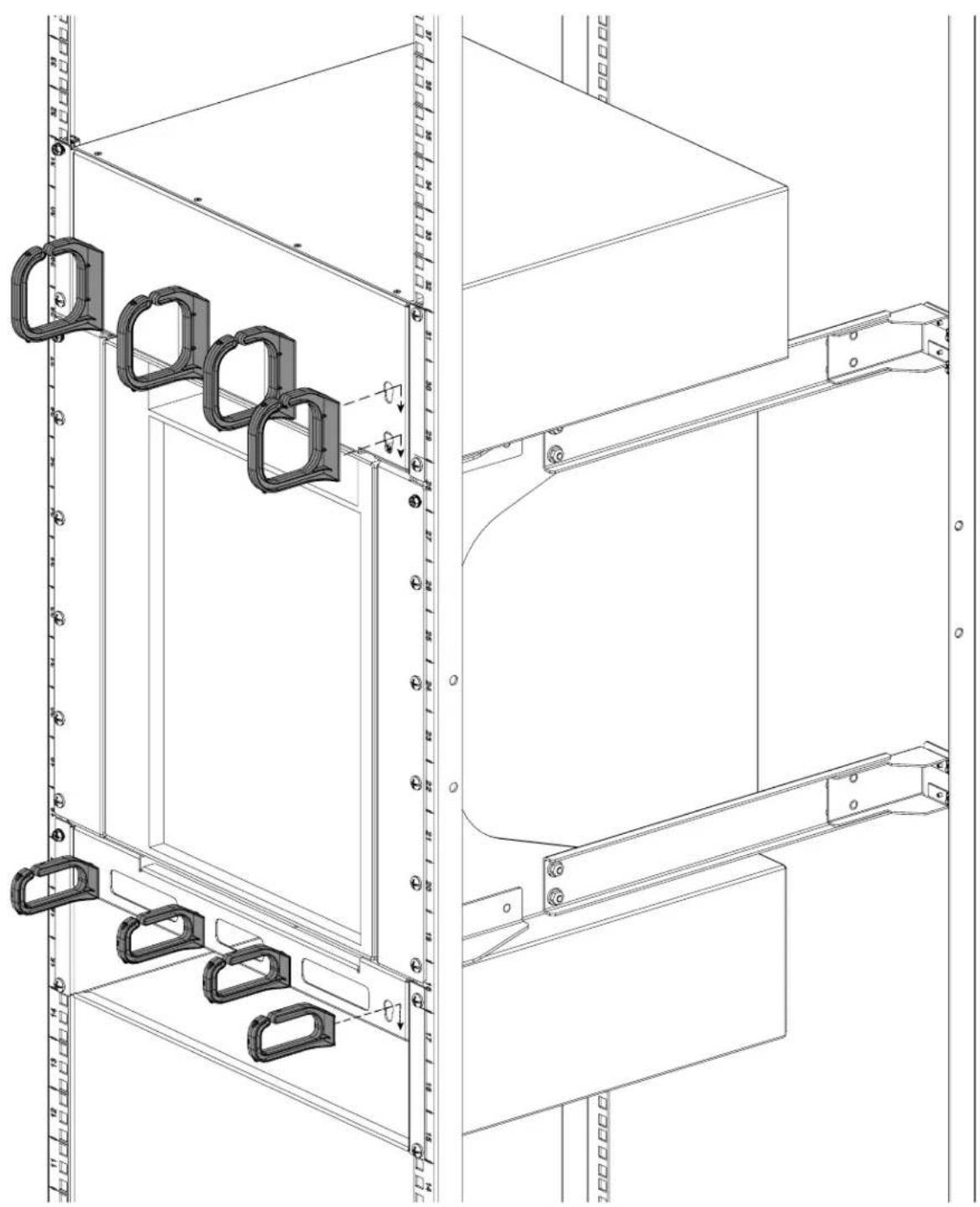
- Cable Managers are inserted into Keyholes and pushed downward to lock into place (Figure 16).
natural_image
Technical line drawing of a mechanical assembly with hanging components and mounting brackets (no text or symbols)Figure 16
For Instructions in Local Languages and Technical Support:
www.panduit.com/resources/install_maintain.asp
PANDUIT
www.panduit.com
E-mail: techsupport@panduit.com
Phone: 866-405-6654
- 12-24 Bonding
- Preparation
- 17RU Open Space Required
- Chassis Installation
- Remove Mounting Ears
- - Shown below
- Vertical Mounting Bracket Installation
- Optional Filter Bracket Installation
- Cage Nut Installation
- Vertical Mount Chassis Installation into Rack
- Extension Arm Installation
- Adjustable Bracket Installation
- Inlet Duct Installation into Rack
- Exhaust Duct Installation into Rack
- Cable Manager Installation
Brand : Panduit
Model : DIRLC9606RB1
Category : Ventilation system