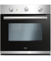
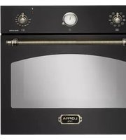
USER MANUAL FOS66GE LOFRA
INSTRUCTIONS AND ADVICE FOR THE INSTALLATION, USE AND MAINTENANCE OF THE GAS OVENS "GAIA E FLEXO" APPARATUS FOR COOKING FOR HOUSEHOLD PURPOSES
CE
ITALIANO
AVVERTENZE PER LA VOSTRA SICUREZZA E CONSIGLI....3
1.1 LOCALE DI INSTALLAZIONE DEL FORNO....7
1.2 SCARICO DEI PRODOTTI DELLA COMBUSTIONE....9
1.3 POSIZIONAMENTO DEL FORNO....9
1.4 ALLACCIAMENTO ALLA RETE DI ALIMENTAZIONE DEL GAS:UNI-CIG 7129/7131....11
1.5 ALLACCIAMENTO ALLA RETE ELETTRICA 11
1.6 ADATTAMENTO A DIVERSI TIPI DI GAS.... 11
2.1 CAVO DI ALIMENTAZIONE ELETTRICO 13
2.2 SMONTAGGIO E MONTAGGIO DELLA PORTA DEL FORNO....13
2.3 SOSTITUZIONE DELLA LAMPADA 13
3.1 FUNZIONAMENTO DEL FORNO....14
3.2 FUNZIONAMENTO DEL GRILL....15
3.3 GIRARROSTO 15
3.4 CONTAMINUTI TOUCH....17
3.5 GUIDE TELESCOPICHE (solo per i modelli previsti)....17
3.6 GRIGLIE CON DISPOSITIVO ANTICADUTA....17
4. PULIZIA....18
5. AVVERTENZE PER IL RISPARMIO ENERGETICO ED IL RISPETTO DELL'AMBIENTE....18
6. GARANZIE .... 19
natural_image
Simple line drawing of a window frame with a black arrow pointing to the left side (no text or symbols)
C): caricare max 3 Kg.
natural_image
Diagram of a kitchen ventilation system with an oven, chimney, and brick wall (no text or symbols)
natural_image
Close-up of a hand using a screwdriver to adjust or install electronic components on a metal panel (no visible text or symbols)

natural_image
Close-up of a metallic heat exchanger or cooling unit mounted on a grid base, with a black arrow pointing to the component (no visible text or symbols)
natural_image
Close-up of a mechanical valve assembly with tubing and fittings (no visible text or symbols)
natural_image
Simple line drawing of a vertical pole with a base and a circular symbol labeled 'B' (no text or symbols present)
2.2 SMONTAGGIO E MONTAGGIO DELLA PORTA DEL FORNO
natural_image
Close-up of a mechanical component with labeled parts (A), showing no readable text or symbols beyond the label.
natural_image
Technical line drawing of an oven with internal shelves and a downward arrow indicating a component (no text or symbols present)
natural_image
Simple diagram with a rectangle, three control buttons (−, Ⓧ, +), and a minus sign in the bottom-left corner (no text or symbols within the diagram itself)
0
natural_image
Simple diagram with a rectangle, three icons below (minus, clock, plus), no text or symbols present.
natural_image
Technical line drawing of a rack-mounted appliance with a magnified inset showing internal components (no text or symbols)
4. PULIZIA
natural_image
Close-up of a transparent rectangular electronic device with metallic leads and a small metallic object on top (no visible text or symbols)
Nuova Lofra S.r.l. reserves the right to modify at any time data and characteristics for technical and operating requirements
WARNINGS AND TIPS FOR YOUR OWN SAFETY
Before using the oven, please read carefully this instruction manual, in order to have all the necessary information for a proper installation.
! = ATTENTION ≈ HOT SURFACE
This appliance has been designed for domestic use only.
All installation, adjustments, conversion and maintenance operations must be carried out by qualified engineers, in accordance with the enclosed instructions and current installation standards.
The manufacturer accepts no liability for faulty installation, setting, handling and use of the appliance.
natural_image
Simple line drawing of a rectangular panel with an arrow pointing to the side (no text or symbols)
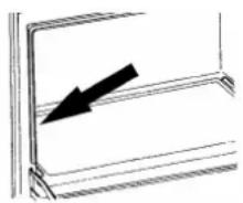
Information about this model and its features is displayed on the plate situated inside the oven door (see the image).
For any service repairs to the appliance, show the service engineer the guarantee and the till receipt with the date of purchase or delivery.
This appliance is not intended for use by person (including children) with reduced physical, sensory or mental capabilities, or lack of experience and knowledge, unless they have been given supervision or instruction concerning use of the appliance by a person responsible for their safety.
⚠ Warning: Accessible parts may become hot during use. Young children should be kept away.
Before carrying out any maintenance or conversion operations, unplug the oven from the mains and shut off the gas upstream of the appliance. If any components and/or accessories need replacing, only original Lofra spare parts must be used. Only qualified technicians may perform installation and maintenance operations
⚠️ Keep the instruction handbook near the oven, so that it can be consulted at any time. This way, the instructions and tips are close at hand for correct use and optimum performance.
Before using the oven remove the plastic protection from the stainless steel, aluminium and/or painted parts in order to prevent it melting. The utmost care must be taken when removing this protection so as to avoid damaging the protected parts.
During use the appliance becomes hot. Care should be taken to avoid touching heating elements inside the oven.
Children aged less than 8 years must be kept away or constantly supervised.
This appliance can be used by children aged from 8 years and above and persons with
reduced physical, sensory or mental capabilities or lack of experience and knowledge if they have been given supervision or instruction concerning use of the appliance in a safe way and understand the hazard involved. Children shall not play with the appliance. Cleaning and user maintenance shall not be made by children without supervision.
Periodically check that there are no gas leaks in the connecting pipe.
When the oven is not in use, ensure that all the knobs are in the off position; furthermore, if it is unused for a period of time, shut off the gas bottle valve and the supply valve, as well as the appliance's mains electricity supply
Before using the oven for the first time, we recommend leaving it on for one hour at the maximum temperature.
⚠️ Doing so may create smoke and unpleasant smells, which are caused by the glue in the heat insulation or oiled plates. To get rid of these odours, air room e.g. opening a window.
⚠️ Some models are fitted with an aluminium tray, ideal for baking pastries (180-200°C): max. load 3 kgs.
Do not cover the bottom of the oven with aluminium foils and do not place the aluminium pan on the bottom of the oven during functioning.
Do not use steel wool, abrasive powders and corrosive substances that could scratch and lead to the breaking of the glass.
Do not use steam cleaners to clean the appliance.
For the ovens that do not have a power cord, this manual indicates the type of cable to use, taking into account the temperature of the rear surface of the device.
The instruction show the correct installation of shelves and trays.
Stationary appliances not fitted with means for disconnection from the supply mains having a contact separation in all poles that provide full disconnection under overvoltage category III, the instructions state that means for disconnection must be incorporated in the fixed wiring in accordance with the wiring rules"
Do not discard packaging, accessories or other parts of the appliance into the environment. If possible, take them to recycling bins or a recycling plant.
If the power cord is damaged, it must be from the manufacturer, its service agent or similarly qualified persons to avoid a hazard; for replacement and / or ovens who do not have to refer to in paragraph 2.1
1. INSTALLATION
All installation, adjustments, conversion and maintenance operations must be carried out by qualified engineers, in accordance with the enclosed instructions and current installation standards. The manufacturer accepts no liability for faulty installation, setting, handling and use of the appliance.

WARNING
Before the installation make sure that local condition of gas distribution (nature and pressure) and the electrical supply (voltage and amperage) are accordant to those indicated on the plate situated on the inner edge of the left side of the appliance. This appliance is not connected to a device for the evacuation of the combustion products.
It must be installed and connected in accordance with the rules in force.
Pay particular attention to the provisions regulating the ventilation of the premises. On each appliance is indicated the type and pressure of the installed standard gas (see the plate).
1.1 PLACE OF INSTALLATION OF THE OVEN

In order to ensure a smooth operation the oven must be installed in a room with a volume of at least 26 m3, permanently ventilated, so that the air, necessary for the correct combustion of the gas (according to the installation regulation in force), is allowed to flow smoothly.
The natural flow of the air must occur directly through:
Permanent holes on the room's walls exposed on the outside; such holes must have a minimum section of 100 cm2 for the models equipped with safety device on the working top, and must be made in a way that they cannot be blocked neither from the inside nor from the outside and placed next to the floor, so that they won't disturb the correct operation of exhaust of combustion.
Single or branched ventilation ducts, Ventilation air should be taken directly from the outside from place without pollution. If air cannot come directly from the outside, indirect ventilation is allowed taking air from the nearby rooms, provided those are not sleeping rooks or rooms with fire hazards; in any case standards UNI-CIG 7129-7131 should be followed.
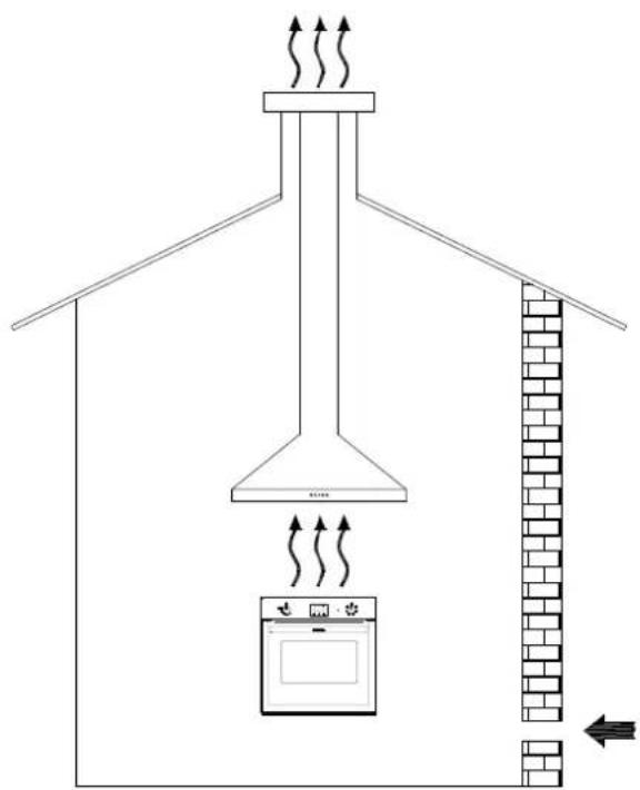
For proper functioning of the gas oven, make sure that there is sufficient air circulation within the rough opening (fig. 1)
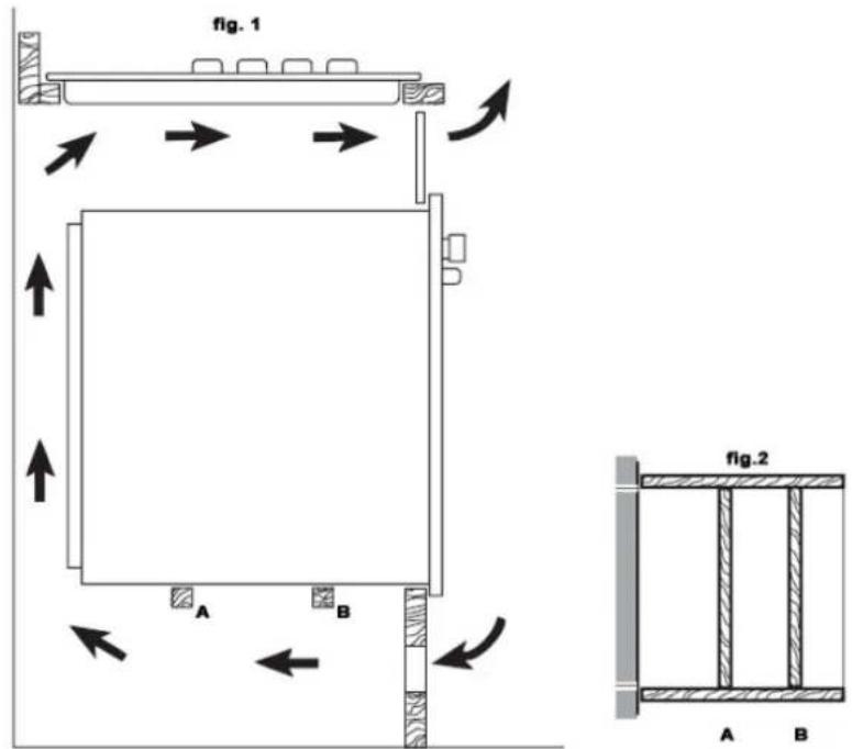
N.B. Fig . 2 , top view of the support base .
Cooking appliances must always discharge the flue gases into special hoods, which must be connected to chimneys, flue pipes or have directly access to the outside. If it is not possible to connect a hood, an electric fan can be fitted to a window or a wall, which must be turned on
when the oven is on, as long as ventilation standards UNI-CIG 7129-7131 are strictly adhered to.
1.3 POSITIONING THE OVENS
The ovens can be installed under the working top or a column of the kitchen. Dimensions for the installation can be found on the below drawings

Don't press on the handle when installing the oven
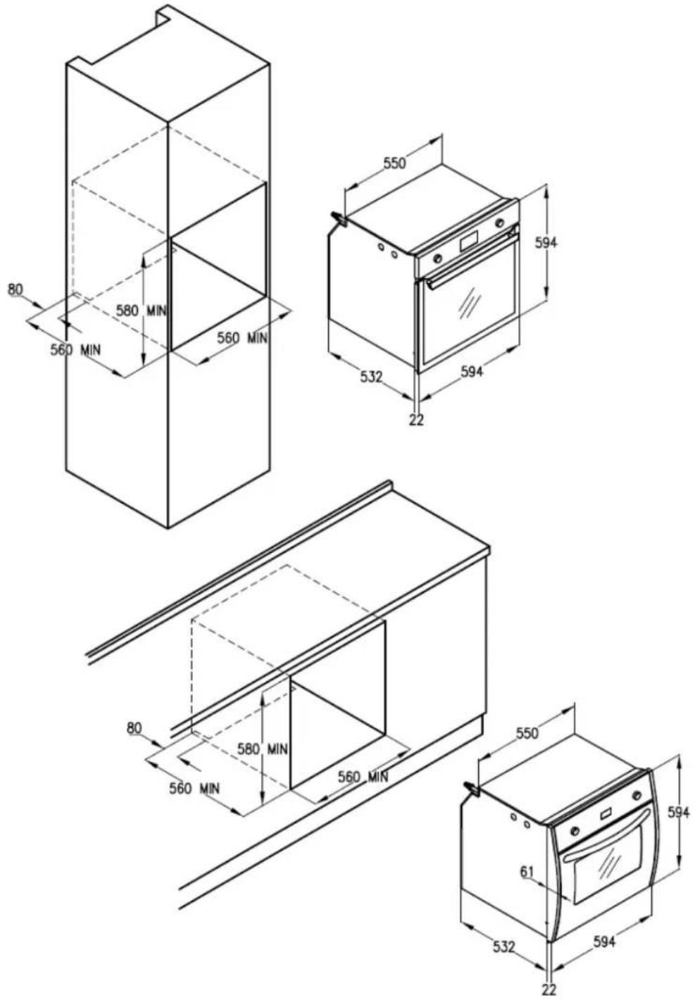
FIXING FLEXO OVEN
In order to install Flexo oven to the cabinet, open the oven door and remove the sides unscrewing the screws under the control panel.
Unthread the sides panels close the oven door and insert the oven in the cabinet.
Open the door once again and screws the burnished self-threading screws for wood with the saves enamelled hems on two holes of 9 mm diameter in the front panel right under the control panel.
Insert the sides, fix the screws unscrewed before under the control panel and close the door.
Fix the self-threading chromed screws (4x25 mm) on the two holes of the sides.
FIXING GAIA OVEN
Insert the oven inside the cabinet and open the door. Insert the 4 burnished self-threading screws for wood with the saves enamelled hems on two holes of 9 mm diameter in the front panel.
Close the oven door.
1.4 CONNECTION TO THE GAS SUPPLY: UNI-CIG 7129/7131
Connection to the gas supply can be made through a rigid metallic pipe conforming to UNI8863 standard, securely attached to the connector, or, through a continuous flexible stainless steel pipe conforming to UNI CIG 9891 standard, which can be extended to a maximum of 2 mt.
The connector “G” and the gasket “C” are supplied as accessories with the appliance and are in accordance with standards UNI ISO 7/1 and UNI 9264
If the appliance is powered on LPG (bottle) a pressure regulator compliant to the standards UNI CIG 7432 must be used.
1.5 CONNECTION TO THE ELECTRICITY SUPPLY
The connection of the oven to the electricity supply can be made through the wire supplied with the appliance or through the wire indicated below. It is necessary to have an all-pole mains isolator in the power network, or that allow

the complete disconnection form the wire, with contacts suitable to the over voltage category III.
1.6 CONVERTING THE GAS-SUPPLY TO THE OVEN BURNERS AND GAS GRILL
Oven burners:
To have access to the oven injector proceed as follows:
- open the oven door and remove the oven base
- unfasten the screw that secures the burner to the inside of the oven and remove the burner from its seat being careful not to damage the thermocouple fixed to it;
- replace the holder injector in accordance with the type of gas used (see table 1)
- put the burner back into its original position

natural_image
Close-up of a hand using a tool to adjust or install electronic components on a metal panel (no visible text or symbols)

natural_image
Close-up of a metallic component with a black arrow pointing to a small feature, placed on a textured surface (no visible text or symbols)
Setting the oven thermostat minimum
Preliminary instructions:
Oven with metal front panel (Gaia): remove the knob of the oven thermostat
Oven with glass front panel (Flexo): unfasten the four screws on the sides and take off the front panel
To set the minimum, proceed as follows:
- open the oven door;
- ight the oven burner and set it to the maximum, close the door and wait for about 10 minutes (or the time required for the oven to heat up to about 230^ ).
- turn the knob to the minimum position, remove it and adjust the by-pass screw until the flame is lowered but stable, even when rapid changes from maximum to minimum are made and the oven door is opened or closed quickly.
N.B.: For liquid gas setting, the oven burner minimum is set by fully tightening the thermostat by-passes.

natural_image
Close-up of a mechanical valve assembly with tubing and components (no visible text or symbols)
Gas grill burners.
To convert the gas to this type of burner, see the “oven burner” instructions above. The only difference is that the burner is in the top of the oven, and there is no need to set the minimum because the burner always works at full power.
FFV66GG (Flexo) - FOS66GG (Gaia)
| Burner | By pass 1/100 mm | Absorbed Power | Bore nozzle (mm) |
| Oven Burner | 40 | 2.5 kW max0,7 kW min | Gas MetanoG20- 20 mbar | Gas liquidoG30 – 28-30 mbar |
| 1,10 | 0,75 |
| Grill Oven Burner | - | 2 kW | 1,05 | 0,70 |
2. MAINTENANCE

WARNINGS :
Before carrying out any maintenance or conversion operations, turn off the electricity supply and close the gas upstream of the appliance. If components and/or accessories need replacing, use original Lofra spare parts only. All the operations hereunder must be carried out by qualified technicians in accordance with the enclosed instructions and current installation standards.
2.1 ELECTRICITY SUPPLY CABLE
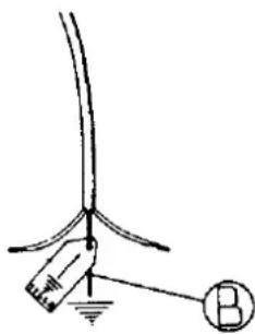
If the electricity supply cable needs replacing, it must be noted that the correct kind for the connection to the electric supply is: H05VV-F 3x1.5mm2 (outer diameter max 9 mm). The earth wire (yellow/green) must be at least 2 cm longer than the other two phase wires. This ensures that the electrics are safe should the wire be pulled accidentally.
A defective cable shouldn't be repaired but replaced with an equivalent one (as listed above).
In this case only authorized LOFRA technicians may replace it.
natural_image
Simple line drawing of a vertical pole with a hanging object and a circle labeled B (no text or symbols)
2.2 REMOVING AND FITTING THE OVEN DOOR
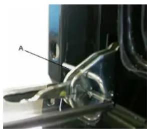
Insert the anti-rotation device in the hook of the hinge rods. Hold the oven door by the sides and slowly close it until you can feel a certain resistance; simultaneously lift the door and force it upwards in order to slide it out by freeing the hinge lock from the kitchen's body. To refit the door repeat the above instructions in reverse making sure the hinge lock is correctly fitted.
natural_image
Close-up of a mechanical component with labeled section A, showing wiring and a metallic rod (no readable text or symbols)
N.B. Attention, reassembling the windows, the writing "REFGLASS" must be read with the door open.
2.3 REPLACING THE BULB
Turn the cooker off at the mains before replacing the bulb.
If recently used, wait for the oven to chill. To identify the bulb see the product label.
Open the oven door, remove the protective glass cover, replace the light bulb (caution: it must be “incandescenza” type: 220-240V – T 300°C – E 14 – 15/25 W or “alogena” (12V –T 250°C – G4 – 5W | 220-240V – T 300°C – G9 – 40 W) and replace the glass protection.
3. USING THE OVEN
WARNINGS:
In case of lack of electricity the cooling fan is not active, therefore it is not recommended to use the oven.
If the burner flames accidentally go out, turn off the knob and wait for at least one minute before igniting.
Using a gas oven produces heat and humidity in the room where it is installed. Ensure the room is well ventilated by keeping all the natural air vents open or by installing a built-in hood with flue pipe.
Intensive or extensive use of the oven could may require supplementary ventilation e.g. increasing the capacity of the mechanic ventilation, if installed.
It's not possible to use the lower burner and the grill gas simultaneously.

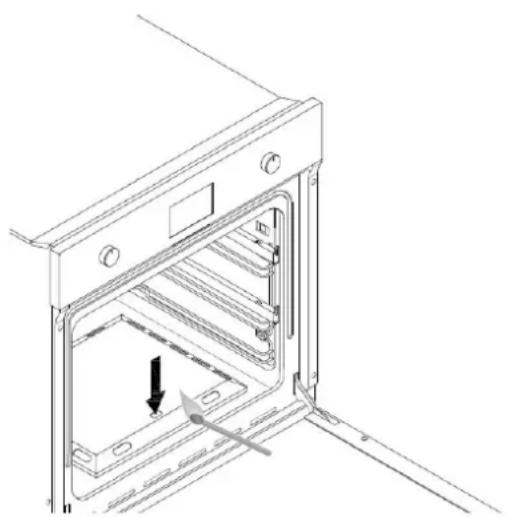
The oven burner must always be ignited with the oven door open.
natural_image
Technical line drawing of an oven with internal shelves and mounting feet (no text or symbols)
The oven burner must always be ignited with the oven door open.
All ovens are fitted with valve thermostats which not only regulate the temperature inside the oven, but also stop the gas flow should the burner go out accidentally, thus avoiding leakage of unburned gas.
The oven door should be opened as little as possible in order to avoid any rapid changes in the oven temperature, which may compromise the cooking results.
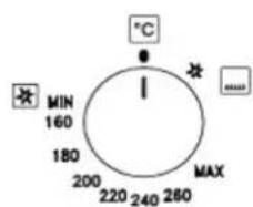
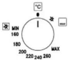
To ignite the burner, press the thermostat knob and turn it in an anti-clockwise direction to the desired temperature. Keep the knob pressed for about 5-10 seconds.
During this time, the burner stays alight by heating the
thermocouple that opens the safety valve and keeps the gas flowing. The automatic ignition device must not be activated for more than 15 seconds. If the burner does not ignite after this time, release the knob and wait for at least 1 minute with oven door opened before trying again. If the electric ignition does not work, bring a lighted match next to the hole that allows you to view the burner and simultaneously press the thermostat knob in the "max" position for about 5-10 seconds.
In case of accidental extinction of the flame turn the knob to the off position and open the door completely.

3.3 USING THE GRILL
The food is laid on the oven grill, which will then be placed inside the oven. The grill's position depends on the type of food, e.g. flat or thin meat should be placed on the level closest to the grill, while a roll of meat, or poultry etc, should be placed on the middle level. The drip tray should be fitted on the guides below the grill.
We recommend using the gas grill to complete oven cooking, therefore for 15-20 minutes at most, or for rotisserie cooking.
All the gas grill have a safety device that automatically stops the gas flow if the burner accidentally goes out. A special two-way thermostat activates the oven burner on the grill burner. The gas grill cannot be regulated as it always works at maximum.
They can be turned on manually or electronically, refer to the indications given for the gas oven burner.
3.4 ROTISSERIE
The rotisserie is used for spit-roasting using the oven and the grill. After placing the drip tray on the bottom shelf, follow these procedures:
- fit the handle to the spit, skewer the food onto the spit and secure it at either end with the two adjustable forks (to avoid the rotisserie motor overworking, try to distribute the food on the spit as evenly as possible)
- place the spit rod into the support and then into the motor shaft;
- loosen the split handle and start the motor with the switch on the front panel, then turn on the grill
3.5 MINUTE TIMER TOUCH CONTROL
Models with electric grill

0

Clock Adjustment

Figure 1
At the first switch the flashing symbols "Auto" and "0.00" will appear. For the first setting, press the central button for about 3 seconds.
When the symbol 📁 appears, press the button "+" or "-" to set the desired time.
Wait, and a beep will indicate that the time has been set (fig.1).
The change of the time set can be made later pressing simultaneously buttons "+" and "-" for 3 seconds and then setting the time as explained above.
MINUTE TIMER

Figure 2
This is only a timer and does not affect the oven operations, therefore at the end of the counting the oven will continue to function.
To set it, press the central button for 3 seconds, until the symbol 🔒 appears (figure 2). With buttons "+" and "-" set the desired time.
For a subsequent adjustment of the timer, press again the central button for 3 seconds and set the desired time.
A beep will indicate the end of the counting. To turn it off, press any button.
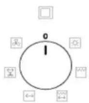
LIST OF FUNCTIONS

1 Oven light

2 Grill
The heat is radiated in the oven. Ideal for grilling, browning, and au gratin dishes.

3 Grill + Rotisserie

4 Rotisserie

5 Oven ventilation + Rotisserie

6 Oven ventilation
Models with gas grill

natural_image
Simple diagram with a rectangle, three directional buttons below (left, right, plus), no text or symbols present.
0

Clock Adjustment

Figure 1
At the first switch the flashing symbols "Auto" and "0.00" will appear. For the first setting, press the central button for about 3 seconds.
When the symbol 📁 appears, press the button “+” or “-” to set the desired time.
Wait, and a beep will indicate that the time has been set (fig.1).
The change of the time set can be made later pressing simultaneously buttons "+" and "-" for 3 seconds and then setting the time as explained above.
MINUTE TIMER

Figure 2
This is only a timer and does not affect the oven operations, therefore at the end of the counting the oven will continue to function.
To set it, press the central button for 3 seconds, until the symbol 🔒 appears (figure 2). With buttons “+” and “-” set the desired time.
For a subsequent adjustment of the timer, press again the central button for 3 seconds and set the desired time.
A beep will indicate the end of the counting. To turn it off, press any button.
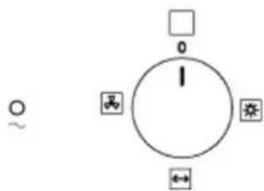
LIST OF FUNCTIONS

1 Oven light

2 Rotisserie

3 Oven ventilation
3.6 TELESCOPIC GUIDES (ONLY FOR CERTAIN MODELS)
The telescopic guides guarantee greater stability to the oven accessories. Placing the food on the shelves or on the tray is easier and safer.
The shelves and trays must be securely fitted into their housing on the guides.
We recommend using oven gloves during cooking or when the oven is still hot.
3.7 TRAYS WITH ANTI-FALL DEVICE
The tray are equipped with safety system to prevent its extraction out of the oven.
When inserting, check that the anti-fall device (see the picture) is always on the back.
The trays can be extracted from the oven only if raised from the front.
4. CLEANING
Before cleaning disconnect the mains and leave the oven to cool.
Clean the oven after each use in order to prevent build-ups of stubborn dirt that are difficult to remove and may damage the surfaces.
To clean the stainless steel, enamelled, and glass parts and the control panel, we recommend using a sponge or damp cloth with a non-abrasive cleaner. If spots are difficult to take off, please use specific cleaning products. Rinse and dry carefully after the cleaning. Do not use steel wool, abrasive powders and corrosive substances that could scratch.

natural_image
Technical line drawing of a rack-mounted appliance with a magnified inset showing internal structure (no text or symbols)
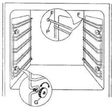
To keep the internal enamelled parts shiny for long time, they
should be cleaned frequently with warm soapy water. The grid guides and drip pan can be removed by unscrewing the nuts/washers G for more thorough cleaning. Refit the parts by placing the 2P extensions of the side guides in the holes F on the bottom of the oven; line up the 2 front eyelets of the guides with the screws fitted to the sides, then secure the guides with nuts/washers G. Do not wash the oven when it is still hot and do not use abrasive substances or products.

No Ensure that enamelled surface do not come into prolonged contact with
acid and alkaline substances, such as: VINEGAR, COFFEE, MILK, SALT WATER, LEMON JUICE, TOMATO JUICE, ETC.
Do not use steam cleaners.
natural_image
Close-up of a transparent glass table with a small metallic object on top, supported by a metal frame (no text or symbols visible)
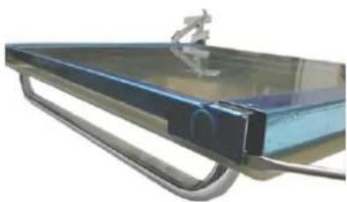
To clean the internal glasses of the oven door, according to the model, remove the top frame using a screwdriver, as illustrated in figure, and slide the glass out of the guides. Take the utmost care when doing these operations
5. WARNINGS FOR ENERGY SAVING AND ENVIRONMENTAL RESPECT

Don't use the oven with door opened to heat the room
Periodically check the integrity of the oven door gasket
It is possible to exploit the thermal inertia, turning off the oven about 10 minutes before the scheduled cooking time.
The packaging of the appliance must be recycled at the points of collections.
A oven out of use must be carried to the Waste Collection Centers.
The presence of the symbol below indicates that the appliance is included in the “new waste” category, therefore subject to recycling. (no urban waste)
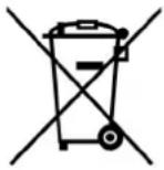

In accordance to article 13 of the 25th of July 2005 legislative decree, no.151 “Implementation of the 2002/95/CE, 2002/96/CE e 2003/108/CE directives on the restriction of the use and waste of certain hazardous substances in electrical and electronic equipment”
The crossed waste bin symbol on the appliance or on its packaging indicates that when the product is worn out and of no further use it must be disposed of separately from other discarded items. Thus, the user has to dispose of the appliance in the appropriate disposal site or arrange with the supplier of the new replacement appliance to dispose of it. The correct disposal of the appliance, insuring it gets correctly recycled, helps avoiding possible environment and health damage and contributes to the reuse and/or recycle of the materials the appliance is made of.
The incorrect disposal of the appliance by the user is subject to the laws in force.
Sede Via Montegrotto, 125 – 35038 TORREGLIA (PADOVA) – ITALY
Tel.: +39 049 9904811
Telefax: +39 049 9904800