IDEALARC AC1500 - Welding machine LINCOLN ELECTRIC - Free user manual and instructions
Find the device manual for free IDEALARC AC1500 LINCOLN ELECTRIC in PDF.


| Product Type | AC Welding Power Source |
| Brand | Lincoln Electric |
| Model | IDEALARC AC1500 |
| Input Voltage | 230V or 460V, 3-Phase, 60 Hz |
| Output Current Range | 100-1500 A AC |
| Duty Cycle | 60% at 1500A |
| Open Circuit Voltage | 80 VAC |
| Weight | Approximately 2000 lbs (907 kg) |
| Dimensions (H x W x D) | 48 x 30 x 36 inches (122 x 76 x 91 cm) |
| Cooling System | Forced air fan |
| Insulation Class | Class H |
| Protection Class | IP23 |
| Welding Processes | Stick (SMAW), Air Carbon Arc Gouging (CAC-A) |
| Electrode Size Range | 1/8 in. to 1/2 in. (3.2 mm to 12.7 mm) |
| Fan Shutdown | Automatic upon cool-down |
| Thermal Protection | Automatic resetting thermostat |
| Warranty | 1 year from date of purchase |
| Operation Manual | 29 pages, English |
| Recommended Electrode Type | E6010, E7018, E7024, etc. |
| Input Cable Size | #4 AWG or larger per code |
| Output Cable Size | 500 MCM or as needed for duty cycle |
| Certifications | UL, CSA, CE (varies by region) |
Frequently Asked Questions - IDEALARC AC1500 LINCOLN ELECTRIC
User questions about IDEALARC AC1500 LINCOLN ELECTRIC
0 question about this device. Answer the ones you know or ask your own.
Ask a new question about this device
Download the instructions for your Welding machine in PDF format for free! Find your manual IDEALARC AC1500 - LINCOLN ELECTRIC and take your electronic device back in hand. On this page are published all the documents necessary for the use of your device. IDEALARC AC1500 by LINCOLN ELECTRIC.
USER MANUAL IDEALARC AC1500 LINCOLN ELECTRIC
For use with machines having Code Numbers:
11418

Register your machine:
www.lincolnelectric.com/register
Authorized Service and Distributor Locator:
www.lincolnelectric.com/locator
Save for future reference
Date Purchased
Code: (ex: 10859)
Serial: (ex: U1060512345)
WARNING
! CALIFORNIA PROPOSITION 65 WARNINGS
!
Diesel engine exhaust and some of its constituents are known to the State of California to cause cancer, birth defects, and other reproductive harm.
The Above For Diesel Engines
The engine exhaust from this product contains chemicals known to the State of California to cause cancer, birth defects, or other reproductive harm.
The Above For Gasoline Engines
ARC WELDING CAN BE HAZARDOUS. PROTECT YOURSELF AND OTHERS FROM POSSIBLE SERIOUS INJURY OR DEATH. KEEP CHILDREN AWAY. PACEMAKER WEARERS SHOULD CONSULT WITH THEIR DOCTOR BEFORE OPERATING.
Read and understand the following safety highlights. For additional safety information, it is strongly recommended that you purchase a copy of "Safety in Welding & Cutting - ANSI Standard Z49.1" from the American Welding Society, P.O. Box 351040, Miami, Florida 33135 or CSA Standard W117.2-1974. A Free copy of "Arc Welding Safety" booklet E205 is available from the Lincoln Electric Company, 22801 St. Clair Avenue, Cleveland, Ohio 44117-1199.
BE SURE THAT ALL INSTALLATION, OPERATION, MAINTENANCE AND REPAIR PROCEDURES ARE PERFORMED ONLY BY QUALIFIED INDIVIDUALS.

FOR ENGINE powered equipment.
1.a. Turn the engine off before troubleshooting and maintenance work unless the maintenance work requires it to be running.

1.b. Operate engines in open, well-ventilated areas or vent the engine exhaust fumes outdoors.

1.c. Do not add the fuel near an open flame welding arc or when the engine is running. Stop the engine and allow it to cool before refueling to prevent spilled fuel from vaporizing on contact with hot engine parts and igniting. Do not spill fuel when filling tank. If fuel is spilled, wipe it up and do not start engine until fumes have been eliminated.
1.d. Keep all equipment safety guards, covers and devices in position and in good repair. Keep hands, hair, clothing and tools away from V-belts, gears, fans and all other moving parts when starting, operating or repairing equipment.
1.e. In some cases it may be necessary to remove safety guards to perform required maintenance. Remove guards only when necessary and replace them when the maintenance requiring their removal is complete. Always use the greatest care when working near moving parts.

1.f. Do not put your hands near the engine fan. Do not attempt to override the governor or idler by pushing on the throttle control rods while the engine is running.
1.g. To prevent accidentally starting gasoline engines while turning the engine or welding generator during maintenance work, disconnect the spark plug wires, distributor cap or magneto wire as appropriate.

1.h. To avoid scalding, do not remove the radiator pressure cap when the engine is hot.

ELECTRIC AND MAGNETIC FIELDS may be dangerous
2.a. Electric current flowing through any conductor causes localized Electric and Magnetic Fields (EMF). Welding current creates EMF fields around welding cables and welding machines
2.b. EMF fields may interfere with some pacemakers, and welders having a pacemaker should consult their physician before welding.
2.c. Exposure to EMF fields in welding may have other health effects which are now not known.
2.d. All welders should use the following procedures in order to minimize exposure to EMF fields from the welding circuit:
2.d.1. Route the electrode and work cables together - Secure them with tape when possible.
2.d.2. Never coil the electrode lead around your body
2.d.3. Do not place your body between the electrode and work cables. If the electrode cable is on your right side, the work cable should also be on your right side.
2.d.4. Connect the work cable to the workpiece as close as possible to the area being welded.
2.d.5. Do not work next to welding power source.

ELECTRIC SHOCK can kill.
3.a. The electrode and work (or ground) circuits are electrically "hot" when the welder is on. Do not touch these "hot" parts with your bare skin or wet clothing. Wear dry, hole-free es to insulate hands.
3.b. Insulate yourself from work and ground using dry insulation. Make certain the insulation is large enough to cover your full area of physical contact with work and ground.
In addition to the normal safety precautions, if welding must be performed under electrically hazardous conditions (in damp locations or while wearing wet clothing; on metal structures such as floors, gratings or scaffolds; when in cramped positions such as sitting, kneeling or lying, if there is a high risk of unavoidable or accidental contact with the workpiece or ground) use the following equipment:
- Semiautomatic DC Constant Voltage (Wire) Welder.
• DC Manual (Stick) Welder.
• AC Welder with Reduced Voltage Control.
3.c. In semiautomatic or automatic wire welding, the electrode, electrode reel, welding head, nozzle or semiautomatic welding gun are also electrically "hot".
3.d. Always be sure the work cable makes a good electrical connection with the metal being welded. The connection should be as close as possible to the area being welded.
3.e. Ground the work or metal to be welded to a good electrical (earth) ground.
3.f. Maintain the electrode holder, work clamp, welding cable and welding machine in good, safe operating condition. Replace damaged insulation.
3.g. Never dip the electrode in water for cooling.
3.h. Never simultaneously touch electrically "hot" parts of electrode holders connected to two welders because voltage between the two can be the total of the open circuit voltage of both welders.
3.i. When working above floor level, use a safety belt to protect yourself from a fall should you get a shock.
3.j. Also see Items 6.c. and 8.
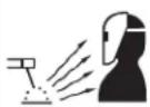
ARC RAYS can burn.
4.a. Use a shield with the proper filter and cover plates to protect your eyes from sparks and the rays of the arc when welding or observing open arc welding. Headshield and filter lens should conform to ANSI Z87. I standards.
4.b. Use suitable clothing made from durable flame-resistant material to protect your skin and that of your helpers from the arc rays.
4.c. Protect other nearby personnel with suitable, non-flammable screening and/or warn them not to watch the arc nor expose themselves to the arc rays or to hot spatter or metal.

FUMES AND GASES can be dangerous.
5.a. Welding may produce fumes and gases hazardous to health. Avoid breathing these fumes and gases. When welding, keep your head out of the fume. Use enough ventilation and/or exhaust at the arc to keep
fumes and gases away from the breathing zone. When welding with electrodes which require special ventilation such as stainless or hard facing (see instructions on container or MSDS) or on lead or cadmium plated steel and other metals or coatings which produce highly toxic fumes, keep exposure as low as possible and within applicable OSHA PEL and ACGIH TLV limits using local exhaust or mechanical ventilation. In confined spaces or in some circumstances, outdoors, a respirator may be required. Additional precautions are also required when welding on galvanized steel.
- b. The operation of welding fume control equipment is affected by various factors including proper use and positioning of the equipment, maintenance of the equipment and the specific welding procedure and application involved. Worker exposure level should be checked upon installation and periodically thereafter to be certain it is within applicable OSHA PEL and ACGIH TLV limits.
5.c. Do not weld in locations near chlorinated hydrocarbon vapors coming from degreasing, cleaning or spraying operations. The heat and rays of the arc can react with solvent vapors to form phosgene, a highly toxic gas, and other irritating products.
5.d. Shielding gases used for arc welding can displace air and cause injury or death. Always use enough ventilation, especially in confined areas, to insure breathing air is safe.
5.e. Read and understand the manufacturer's instructions for this equipment and the consumables to be used, including the material safety data sheet (MSDS) and follow your employer's safety practices. MSDS forms are available from your welding distributor or from the manufacturer.
5.f. Also see item 1.b.

WELDING and CUTTING SPARKS can cause fire or explosion.
6.a. Remove fire hazards from the welding area. If this is not possible, cover them to prevent the welding sparks from starting a fire.
Remember that welding sparks and hot materials from welding can easily go through small cracks and openings to adjacent areas. Avoid welding near hydraulic lines. Have a fire extinguisher readily available.
6.b. Where compressed gases are to be used at the job site, special precautions should be used to prevent hazardous situations. Refer to "Safety in Welding and Cutting" (ANSI Standard Z49.1) and the operating information for the equipment being used.
6.c. When not welding, make certain no part of the electrode circuit is touching the work or ground. Accidental contact can cause overheating and create a fire hazard.
6.d. Do not heat, cut or weld tanks, drums or containers until the proper steps have been taken to insure that such procedures will not cause flammable or toxic vapors from substances inside. They can cause an explosion even though they have been "cleaned". For information, purchase "Recommended Safe Practices for the Preparation for Welding and Cutting of Containers and Piping That Have Held Hazardous Substances", AWS F4.1 from the American Welding Society (see address above).
6.e. Vent hollow castings or containers before heating, cutting or welding. They may explode.
6.f. Sparks and spatter are thrown from the welding arc. Wear oil free protective garments such as leather gloves, heavy shirt, cuffless trousers, high shoes and a cap over your hair. Wear ear plugs when welding out of position or in confined places. Always wear safety glasses with side shields when in a welding area.
6.g. Connect the work cable to the work as close to the welding area as practical. Work cables connected to the building framework or other locations away from the welding area increase the possibility of the welding current passing through lifting chains, crane cables or other alternate circuits. This can create fire hazards or overheat lifting chains or cables until they fail.
6.h. Also see item 1.c.
6.1. Read and follow NFPA 51B "Standard for Fire Prevention During Welding, Cutting and Other Hot Work", available from NFPA, 1 Batterymarch Park, PO box 9101, Quincy, Ma 022690-9101.
6.j. Do not use a welding power source for pipe thawing.

CYLINDER may explode if damaged.
7.a. Use only compressed gas cylinders containing the correct shielding gas for the process used and properly operating regulators designed for the gas and used. All hoses, fittings, etc. should be suitable for tion and maintained in good condition.
7.b. Always keep cylinders in an upright position securely chained to an undercarriage or fixed support.
7.c. Cylinders should be located:
- Away from areas where they may be struck or subjected to physical damage.
- A safe distance from arc welding or cutting operations and any other source of heat, sparks, or flame.
7.d. Never allow the electrode, electrode holder or any other electrically "hot" parts to touch a cylinder.
7.e. Keep your head and face away from the cylinder valve outlet when opening the cylinder valve.
7.f. Valve protection caps should always be in place and hand tight except when the cylinder is in use or connected for use.
7.g. Read and follow the instructions on compressed gas cylinders, associated equipment, and CGA publication P-1, "Precautions for Safe Handling of Compressed Gases in Cylinders," available from the Compressed Gas Association 1235 Jefferson Davis Highway, Arlington, VA 22202.

FOR ELECTRICALLY powered equipment.
8.a. Turn off input power using the disconnect switch at the fuse box before working on the equipment.
8.b. Install equipment in accordance with the U.S. National Electrical Code, all local codes and the manufacturer's recommendations.
8.c. Ground the equipment in accordance with the U.S. National Electrical Code and the manufacturer's recommendations.
Refer to http://www.lincolnelectric.com/safety for additional safety information.
PRÉCAUTIONS DE SÛRETÉ
for selecting a QUALITY product by Lincoln Electric. We want you to take pride in operating this Lincoln Electric Company product … as much pride as we have in bringing this product to you!
CUSTOMER ASSISTANCE POLICY
The business of The Lincoln Electric Company is manufacturing and selling high quality welding equipment, consumables, and cutting equipment. Our challenge is to meet the needs of our customers and to exceed their expectations. On occasion, purchasers may ask Lincoln Electric for advice or information about their use of our products. We respond to our customers based on the best information in our possession at that time. Lincoln Electric is not in a position to warrant or guarantee such advice, and assumes no liability, with respect to such information or advice. We expressly disclaim any warranty of any kind, including any warranty of fitness for any customer's particular purpose, with respect to such information or advice. As a matter of practical consideration, we also cannot assume any responsibility for updating or correcting any such information or advice once it has been given, nor does the provision of information or advice create, expand or alter any warranty with respect to the sale of our products.
Lincoln Electric is a responsive manufacturer, but the selection and use of specific products sold by Lincoln Electric is solely within the control of, and remains the sole responsibility of the customer. Many variables beyond the control of Lincoln Electric affect the results obtained in applying these types of fabrication methods and service requirements.
Subject to Change – This information is accurate to the best of our knowledge at the time of printing. Please refer to www.lincolnelectric.com for any updated information.
Please Examine Carton and Equipment For Damage Immediately
When this equipment is shipped, title passes to the purchaser upon receipt by the carrier. Consequently, Claims for material damaged in shipment must be made by the purchaser against the transportation company at the time the shipment is received.
Please record your equipment identification information below for future reference. This information can be found on your machine nameplate.
Product
Model Number
Code Number or Date Code
Serial Number
Date Purchased
Where Purchased
Whenever you request replacement parts or information on this equipment, always supply the information you have recorded above. The code number is especially important when identifying the correct replacement parts.
On-Line Product Registration
- Register your machine with Lincoln Electric either via fax or over the Internet.
- For faxing: Complete the form on the back of the warranty statement included in the literature packet accompanying this machine and fax the form per the instructions printed on it.
- For On-Line Registration: Go to our WEB SITE at www.lincolnelectric.com. Choose “Quick Links” and then “Product Registration”. Please complete the form and submit your registration.
Read this Operators Manual completely before attempting to use this equipment. Save this manual and keep it handy for quick reference. Pay particular attention to the safety instructions we have provided for your protection. The level of seriousness to be applied to each is explained below:

WARNING
This statement appears where the information must be followed exactly to avoid serious personal injury or loss of life.

CAUTION
This statement appears where the information must be followed to avoid minor personal injury or damage to this equipment.
Installation......Section A
Technical Specifications....A-1
Location A-2
Input Wiring A-2
Output Connections....A-2
Wire Feeder Connections ......A-2
Connection of AC-1500 to NA-4 with Switch for 'Current Control' ......A-3
Connection of AC-1500 to NA-4 with rheostat for current control or LT-6....A-3
Output Studs ......A-4
Auxiliary Power A-4
Duty Cycle A-4
Operation......Section B
Safety Precautions and Graphic Symbols......B-1
Product Design Application B-2
Setting the Machine or Remote Control B-2
Setting the Output Current B-2
Weld with Manual Electrodes....B-2
Product Description ......B-2,B-3
Accessories......Section C
Optional Kit....C-1
Maintenance ....Section D
Safety Precautions ....D-1
Troubleshooting......Section E
Safety Precautions....E-1
How to Use Troubleshooting Guide....E-1
Troubleshooting Guide....E-2,E-3
Wiring Diagrams and Dimension Print......Section F
Parts Pages....P-556, P-28, P-84 Series
TECHNICAL SPECIFICATIONS - IDEALARC® AC-1500
| INPUT - SINGLE PHASE ONLY | ||
| Standard Voltage | Input Current at 100% Rated Output Single Phase Output Scott Connection | |
| 380/50/60 | 310 358 | |
| Rated Input Current With P.F. Capacitors310 Amp Single Phase358 Amp Scott-connection | Idle Current With P.F. Capacitors70 | |
| Power Factor @ Rated load With P.F. Capacitors71% | ||
RECOMMENDED INPUT WIRE GROUNDING CONDUCTOR AND FUSE SIZES*
| Input Volts/ Hz. | Input Amps Copper Wire Size – 75°C in Conduit Super Lag Fuses | Size in Amps | ||||||||||
| 1 Phase | Scott Conn. | 1 Phase | T&B Term. | Scott Conn. | T&B Term. | 1 Phase | T&B Term. | Scott Conn. | T&B Term. | 1 Phase | Scott Conn. | |
| 380/50 | 310 | 358 | 500MCM (250mm2) | 31013 300mm | 600MCM 2) | 31015 25mm | #3 2) | 31007 35mm | #2 2) | 31007 | 400 | 500 |
RATED OUTPUT
| Duty Cycle100% | AMPS AC1500 @ 44 Volts |
| Current Range240/1500 | |
OUTPUT (SMAW)
| “MIN” Terminal | “MED” Terminal | “MAX” Terminal | |
| Volts | 30-44 | 38-44 | 44 |
| Amps | 240-600 | 460-1060 | 890-1500 |
| Maximum Open Circuit Voltage | 86 | ||
PHYSICAL DIMENSIONS
| Height | Width | Depth | Weight |
| 53.50 in.(1358.9mm.) | 22.30 in.(566.4mm.) | 38.00in.(965.2mm.) | 1649lbs.748(kg.) |
* Thomas & Betts wire terminals (or equal) recommended above are required to comply with applicable U.L. standards for safety. A #30 hex (Allen) key wrench is required for assembly of terminals to wire. Based on National Electrical Code - 100% Duty Cycle 40°C (104°F) Ambient.
RATING: IP21 ENCLOSURE, INSULATION 155°(F)
LOCATION
Install the welder in a dry location where there is free circulation of air in through the louvers in front and out through the louvers in the back of the case. A location which minimizes the amount of smoke and dirt drawn into the machine reduces the chance of dirt accumulation that can block air passages and cause overheating.
INPUT WIRING

WARNING

ELECTRIC SHOCK
• Have an electrician install and service this equipment.
- Turn the input power off at the fuse box before working on equipment.
- Do not touch electrically hot parts.
Failure to fuse the input lines per the specifications in this manual will constitute customer abuse and void the warranty.
Have a qualified electrician make the complete input connection in accordance with the National Electrical Code, all local codes and the connection diagram located inside the machine.
Be sure the voltage, phase and frequency of the input power is as specified on the welder nameplate.
For most installations, connect the AC-1500 to single phase power or to one phase of a three phase line. Unbalanced line conditions can be easily avoided by properly balancing the AC-1500 with other machinery on the lines.
When installing two or four Scott connected AC-1500 machines for AC-AC tandem arc welding, three phase input power must be used. The terminals for connections to provide an output phase angle less than or greater than the usual 90° phase angle are included on the input panel.
The AC-1500 does not have an input contactor. Therefore, include an external starter or disconnect switch when planning the input circuit.
Remove the right side panel of the AC-1500 and bring the input power lines through the hole in the back of the case. See the table below for recommended sizing of input leads and overcurrent protection.
The frame of the welder must be grounded, A stud marked with the symbol located on the welder base below the panel is provided for this purpose. See the National Electrical Code for details on proper grounding methods.
OUTPUT CONNECTIONS
WIRE FEEDER CONNECTION
Turn the input power to the welder off. Remove the screw and lift the hinged door on the front of the control panel to expose the terminal strips. Connect the leads of the wire feeder input control cable to the terminal strips exactly as specified in the appropriate connection diagram. The AC-1500 to NA-4 connection diagrams are included in the NA-4 Operating Manual IM-278. Attach the control cables to the panel at the right of the terminal strip using the clamps provided.
If connecting the AC-1500 to an older NA-4 with the toggle switch type 'Current Control' (below code 7532), a K-775 'Remote Control' must be purchased and installed in accordance with the connection diagram S-15667 on page 5. The 'Remote Control' cord can be lengthened to any length by properly splicing a four conductor cord to the standard 25' cord before connecting to the AC-1500 terminal strip.
To connect the AC-1500 to any other wire feeder, write to the factory for instructions giving complete nameplate information for the specific equipment.
When connection to the terminal strips are completed, close the door and replace the screw.
Connection of AC-1500 to NA-4 S-15667
with Switch for 'Current Control' 6-18-76A
CONNECT THE CONTROL CABLE GROUND LEAD TO THE FRAME TERMINAL MARKED → NEAR THE POWER SOURCE TERMINAL STRIP.
THE POWER SOURCE MUST BE PROPERLY GROUNDED.
N.A. WELDING CABLES MUST BE OF PROPER CAPACITY FOR THE CURRENT AND DUTY CYCLE OF IMMEDIATE AND FUTURE APPLICATIONS
![graph TD A["AC-1500"] --> B["TO AUTOMATIC CONTROL BOX"] B --> C["CONTROL CABLE"] C --> D["TAPE LEADS SEPARATELY"] D --> E["REMOTE CURRENT CONTROL RHEOSTAT"] E --> F["21"] E --> G["4"] E --> H["31"] E --> I["2"] E --> J["32"] K["ELECT."] --> L["N.A."] M["WORK"] --> N["TO WORK"]](/content/2026/06/1403566/images/51600c06dfb10c170cf2b8b424f60b34e9527564294f08057d63fe0083cb2546.jpg)
FOR NA-4 WITH CODES 7531 AND LOWER
Connection of AC-1500 to NA-4 with rheostat for current control.
WARNING: Turn power source off before making these connections. Connect the control cable ground lead to the frame terminal marked near the power source terminal strip. The power source grounding terminal (marked and located near the power source input power connections) must also be connected to electrical ground per the power source Operating Manual.
N.A. Welding cables must be of proper capacity for the current and duty cycle of immediate and future applications. See the Operating Manual for proper sizes.
N.B. Extend lead 21 using #14 or larger insulated wire physically suitable for the installation. An S-16586 remote voltage sensing work lead is available for this purpose. Connect it directly to the work piece keeping it electrically separate from the welding work lead circuit and connection.
N.C. If using an older control cable: connect lead #75 to #75 on terminal strip, connect lead #76 to #76 on terminal strip, connect lead #77 to #77 on terminal strip.
N.D. To avoid possible induced NA-4 or LT-6 meter reading error; keep the control leads, including the extended #21 lead separated from the A.C. welding cables by at least 12 inches.
![graph TD A["AC-1500"] --> B["GND."] B --> C["To Automatic Control Box"] A --> D["N.C."] D --> E["32"] E --> F["2"] F --> G["31"] G --> H["4"] H --> I["76"] I --> J["75"] J --> K["21"] K --> L["32"] L --> M["2"] M --> N["31"] N --> O["77"] O --> P["76"] P --> Q["75"] style A fill:#f9f,stroke:#333 sty…](/content/2026/06/1403566/images/ea68f5b022c31c173a1ad89d1004299075e851f4072f6af11c0854f966cfff15.jpg)
S-15602
6-22-84H
OUTPUT STUDS
Connect the work cables to the 'To Work' stud on the front of the AC-1500. Connect the electrode cables to the 'Min,' 'Med' or 'Max' studs for the output desired. Actual current ranges for each stud are indicated on the nameplate above each stud. Recommended cable sizes are listed below. Both the 'To Work' and 'Max' studs have two terminals to simplify connection of recommended cables in parallel. Tighten the nuts with a wrench.
Select cables required for combined work and electrode cable lengths up to 150' from the following table:
Maximum Allowable Current for Copper Welding Cable
| Duty Cycle One | 4/0 | Two 4/0 | Four 4/0 | Five 4/0 | |
| 100% 650 | 1000 | 1200 | 1500 |
Cables in accessory kit recommended below have terminals as required to comply with applicable U.L. standards for safety.
150' combined length electrode and work cables.
AUXILIARY POWER
1000 volt-amperes of 115 volt AC power are available from #31 and #32 on the AC-1500 terminal strip.
DUTY CYCLE
The AC-1500 is rated for 100% duty cycle at 1500 amps and 44 volts.
SAFETY PRECAUTIONS
Read and understand this entire section before operating the machine.
WARNING

ELECTRIC SHOCK can kill.
- Do not touch electrically live parts or electrode with skin or wet clothing.
• Insulate yourself from work and ground.
• Always wear dry insulating gloves.

FUMES AND GASES can be dangerous.
- Keep your head out of fumes.
- Use ventilation or exhaust to remove fumes from breathing zone.

WELDING SPARKS can cause fire or explosion
- Keep flammable material away.
- Do not weld on containers that have held combustibles.

ARC RAYS can burn.
- Wear eye, ear and body protection.
Observe additional Safety Guidelines detailed throughout this manual.
GRAPHIC SYMBOLS THAT APPEAR ON THIS MACHINE OR IN THIS MANUAL

Output Control

Single Phase

Remote Control Setting

Three Phase

Local Control Settin
Uo Rated No-Load Voltage
Input Power Type
U1 Rated Input Voltage

Submerged Arc Welding
U2 Rated Welding Voltage

Transformer Type
X Rated Duty Cycle
Fuse
I1 Rated Input Current

High Voltage Indicator
I2 Rated Welding Current

High Temperature Indicator

Rated Frequency
PRODUCT DESIGN APPLICATION
The IDEALARC® AC-1500 is an upgraded design with the following additional features:
- Higher output current and duty cycle capabilities.
It is a single phase transformer-saturable reactor type power supply intended for use primarily in automatic or semiautomatic variable voltage AC welding applications. It can be used to supply one automatic welder head or two units may be used in Scott connection to provide two phase power to two welder heads in tandem. The welder can be used as is with NA-4 heads or modified with available options to supply the earlier NA-4 or LAF-4, and LT-34 welding heads.
WARNING
Pipe Thawing with an arc welder can cause fire, explosion, damage to electric wiring or to the arc welder if done improperly. The use of an arc welder for pipe thawing is not approved by the CSA, nor is it recommended or supported by Lincoln Electric.
SETTING THE MACHINE OUTPUT OR REMOTE CONTROL
The output can be controlled either from the AC-1500, the wire feeder or other remote locations.
To adjust the current from the wire feeder or other remote locations, set the toggle switch on the front of the AC-1500 to 'Output Control Remote'. To adjust the output current from the AC-1500, set this switch to 'Output Control at AC-1500'.
SETTING THE OUTPUT CURRENT
Start the AC-1500 using the line disconnect switch or breaker installed with the input wiring. The red pilot light on the front panel indicates when the welder is on.
Adjust the output current from minimum to maximum within the range set by the output stud connections using either the 'Output Control' rheostat on the AC-1500 (toggle switch set to 'Local Control') or the wire feeder or other remote rheostat (toggle switch set to 'Remote Control').
PRODUCT DESCRIPTION
Specifications are 50 Hz, 380 volt unit with a Power factor correction as a standard feature.
Output terminals, control power terminal strip, and controls are recessed or hinged covered to affect a "dead front". Due to the excessive amount of stray magnetic flux developed by the saturable reactor, the center sections of the welder side panels are made of a high impact, self-extinguishing, chemical resistant plastic material. USE OF METALLIC PANELS IN THEIR PLACE WILL RESULT IN EXCESSIVE HEATING OF THE PANELS AS WELL AS THE SHEET METAL SCREWS USED IN THE ASSEMBLY OF OTHER CASE PARTS.
Output welding current is available in three overlapping ranges by means of externally connecting the electrode cables to the Min., Med., or Max. tap electrode studs(See Technical Specifications in the Installation Section).
Input Line Voltage Compensation maintains a reasonably constant output within a range of ±10% change in supply line voltage.
Cooling of the welder is accomplished by drawing air in through the louvered case front panel, through the reactor and transformer assemblies, and out the louvered case rear panel. The two totally enclosed fan motors used have sealed ball bearings and require no lubrication maintenance.
Handling of the welder and any attached devices should be done with a fork-lift or pallet-jack capable of loads exceeding the combined weight of the system.
Overload/Thermal Protection is provided in three areas: the 115 volt AC auxiliary power is fused for 8 amps; the saturable reactor control power circuit is protected by a 40 amp fuse; the welder output power circuit is protected by the familiar current transformer-Klixon thermostat breaker. In the event of a control circuit or welder overload, the output contactors will open and the fan motors will continue to operate. If the overload is detected by the thermostatic breaker, the temperature light located on the front panel will illuminate until a safe operating temperature is reached.
Output Contactor control is provided by two S78 contactors connected in parallel. Input line contactors are not provided. The customer is expected to provide line starting and circuit breaking equipment.
Pilot light indicates when the supply lines to the welder are electrically "hot". This means that the welder input power and control transformers are energized when the pilot light is on.
Input Circuit Plan: The AC-1500 is not intended for the connection of flexible supply cables. Instead, the following table may be used for planning of supply cables routed in conduit (See Technical Specifications in the Installation Section).
Starting Device: The pushbuttons located on the front panel are not connected to any kind of starting or stopping device. They are not necessary to operating the welder. If pushbutton operation is desired, an input contactor must be professionally installed and wired to the pushbutton assembly. The AC-1500 does not have an input contactor. Therefore, include an external starter or disconnect switch when planning the input circuit. Once the input circuit is energized, the pilot light on the front panel should glow. High voltage is present inside the machine. Do not open the machine enclosure.
Input Panel is made accessible by removal of the right side panel assembly (as viewed from front). Supply lines and grounding lead should be brought into the welder through the hole provided in the case rear panel. Connections to the input panel should be made as instructed on the wiring diagram attached to the welder. The grounding lead connection is to be made to the grounding stud provided on the welder base directly below the input panel.
Location of installation should be such that the welder cooling air exhaust area (the case rear panel) is free of any obstructions that could impede air flow. A dry location should be chosen. The welder should not be placed on a surface that is inclined enough that it creates a risk of the machine falling over
Control Circuit connections for wire feeder equipment are to be made per instructions on the wire feeder diagram to the terminal strip provided under the hinged cover on the case front panel of the welding power supply. A strain relief strap to the right of the terminal strip is provided for attaching either the feeder control and remote current control cables or both simultaneously. A grounding screw located just to the right of the terminal strip is provided for connecting the wire feeder grounding lead. All connections must be made with the welding power supply turned off.
Hand Welding with stick electrode or semiautomatic arc welding is not recommended since OCV exceeds the 80 volts RMS limit allowed by standards for such use. (Unit is within 100 volt allowable limit for automatic or mechanically guided welding.)
Scott Connection information for tandem arc application and paralleling of Scott connected units for tandem arc application is available. (See list of wiring diagrams.)
Isolated Auxiliary Power of 1000 volt.-amp., 115 volts AC is available at terminals #31 and #32 on the terminal strip under the hinged cover on the case front panel of the welder. The circuit is fused with an 8 amp slow blow fuse located in the nameplated section of the welder front panel.
OPTIONAL KIT: Remote control K775.
SAFETY PRECAUTIONS
WARNING

ELECTRIC SHOCK can kill.
- Have qualified personnel do the maintenance and troubleshooting work.
- Turn the input power OFF at the disconnect switch or fuse box before working on this equipment.
- Do not touch electrically live parts or electrode with skin or wet clothing.
• Insulate yourself from work and ground.
• Always wear dry insulating gloves.
See additional warning information throughout this operator's manual.
Periodic blowing out of dust and dirt accumulated within the welder using an air stream is recommended. This may be particularly desirable in atmospheres containing chemical or metallic particles which could accumulate within the welder and cause some difficulty.
The totally enclosed fan motors have sealed ball bearings which require no lubrication maintenance.
HOW TO USE TROUBLESHOOTING GUIDE
WARNING
Service and Repair should only be performed by Lincoln Electric Factory Trained Personnel. Unauthorized repairs performed on this equipment may result in danger to the technician and machine operator and will invalidate your factory warranty. For your safety and to avoid Electrical Shock, please observe all safety notes and precautions detailed throughout this manual.
This Troubleshooting Guide is provided to help you locate and repair possible machine malfunctions. Simply follow the three-step procedure listed below.
Step 1. LOCATE PROBLEM (SYMPTOM).
Look under the column labeled "PROBLEM (SYMP-TOMS)". This column describes possible symptoms that the machine may exhibit. Find the listing that best describes the symptom that the machine is exhibiting.
Step 2. POSSIBLE CAUSE.
The second column labeled “POSSIBLE CAUSE” lists the obvious external possibilities that may contribute to the machine symptom.
Step 3. RECOMMENDED COURSE OF ACTION
This column provides a course of action for the Possible Cause, generally it states to contact your local Lincoln Authorized Field Service Facility.
If you do not understand or are unable to perform the Recommended Course of Action safely, contact your local Lincoln Authorized Field Service Facility.
CAUTION
If for any reason you do not understand the test procedures or are unable to perform the tests/repairs safely, contact your Local Lincoln Authorized Field Service Facility for technical troubleshooting assistance before you proceed.
Observe all Safety Guidelines detailed throughout this manual
| PROBLEMS (SYMPTOMS) | POSSIBLE CAUSE | RECOMMENDED COURSE OF ACTION |
| Welder will not start. | Supply line fuse blown.Open supply line lead.Wrong supply line voltage. | Look for possible cause and repair.Replace fuse.Repair.Provide nameplate specified voltage. |
| Welder will not weld (Contactors operating properly) | Electrode or ground cable loose or broken.Welder control circuit dead: No voltage across Control Transformer X1-X2. | Tighten connection or repair broken cable.Check Control Transformer primary voltage and if OK, replace transformer. |
| Welder will not weld (Contactors not operating). | Thermostat on coil tripped. Welder overheated (Fan motors operating).Fuse (or thermostat - below code 7600) on control panel open; Control circuit overloaded. (Fan motors operating)Circuit across #2 and #4 not working properly.Wire feeder control power; No voltage across #31 and #32. | Check operation of fans and make sure there is no obstruction to air flow. Do not operate in excess of welder rating.SCR's or diodes on heat sink assembly or P.C. board failed -see Trouble "Welder welds at max. or min. only - no control". Make repairs and replace fuse.Check connections at terminal strip and wire feeder. Relay contacts not closing. Repair as required.Check fuse and replace if no good. |
| Welder welds at min. only no control. | Remote control switch in wrong position.Control rheostat open.Control circuit open.Open saturable reactor control coil or connection. | Switch to 'Panel Control' for welder rheostat. Control and "Remote Control" for other control.Replace rheostat.No voltage across #41 and #44 -Repair broken leads or reconnect loose leads.Diodes or SCR's on heat sinks open or disconnected. Repair or replace.P.C. board plug disconnected - Check plug connection and plug in properly.P.C. board failed. Determine cause and replace board.Open circuit ar R1 -Repair or replace. Repair connection or replace coil. |
CAUTION
If for any reason you do not understand the test procedures or are unable to perform the tests/repairs safely, contact your Local Lincoln Authorized Field Service Facility for technical troubleshooting assistance before you proceed.
| PROBLEMS (SYMPTOMS) | POSSIBLE CAUSE | RECOMMENDED COURSE OF ACTION |
| Welder welds at max. only no control. | Diodes or SCR's on heat sink assemblies shorted.Shorted or grounded current control rheostat.Output By-Pass Capacitors open or disconnected.Free wheeling diode open or disconnected.P.C. board components failed. | Determine cause if possible and replace shorted device.Replace rheostat.Replace or reconnect.Replace or reconnect.Determine cause if possible and replace P.C. board. |
| Contacts chatter. | Low supply line voltage.Faulty contactor. | Check with Power Company.Repair or replace. |
CAUTION
If for any reason you do not understand the test procedures or are unable to perform the tests/repairs safely, contact your Local Lincoln Authorized Field Service Facility for technical troubleshooting assistance before you proceed.
IDEALARC® AC-1500

IDEALARC® AC-1500 WIRING DIAGRAM

M18868-1
NOTE: This diagram is for reference only. It may not be accurate for all machines covered by this manual. The specific diagram for a particular code is pasted inside the machine on one of the enclosure panels. If the diagram is illegible, write to the Service Department for a replacement. Give the equipment code number.
AC-1500 SCOTT CONNECTION DIAGRAM
TWO SINGLE MACHINES SCOTT CONNECTED
![graph TD A["TEASER TRANSFORMER (TRAIL ARC) AC-1200 OR AC1500"] --> B["MAIN TRANSFORMER (LEAD ARC) AC-1200 OR AC1500"] B --> C["3 PHASE SUPPLY LINES PHASE SEQUENCE A-C-B (N.A.)"] C --> D["LEAD ARC"] D --> E["TRAIL ARC"] E --> F["WORK"] F --> G["N.D.,N.E."] G --> H["ELEC."] H --> I["N.C."] I --> J["WO…](/content/2026/06/1403566/images/e832828649ca69af4221ccc84947841b934ac85177b5d49d328e71fe317d2c3a.jpg)
NOTE: The two arcs must be properly phased relative to each other, if the electrical connections are not as shown above, poor welding will result.
A way to verify the proper phase angle and phase sequence is to measure the A.C. voltage at the welding nozzles.
- Do not weld during the voltage measurements. Back the electrode out of each wire drive, then press the NA-4 start buttons.
CAUTION - Voltage will be high between the two electrode nozzles.
- Voltage readings between nozzles to work, and nozzle to nozzle should be per table;
| PHASE ANGLE | LEAD ARC TO WORK V | TRAIL ARC TO WORK V | LEAD ARC TO TRAIL ARC | |
| Value | Relationship | |||
| 100° | 90 VAC | 90 VAC | 138 VAC | 1.53 x V |
| 90° | 90 VAC | 90 VAC | 127 VAC | 1.41 x V |
| 80° | 90 VAC | 90 VAC | 116 VAC | 1.29 x V |
If voltages do not agree, recheck all wiring and the proper sequence of the input supply lines.
* If using the 900 phase angle connection, the phase sequence cannot be determined by voltage measurement. To determine the phase sequence use one of the following methods.
- Use a phase meter.
-
Use an oscilloscope
-
Temporarily reconnect the machine to either the 100° tap or the 80° tap and check the voltage per note 2.
N.A. To obtain proper phase sequence at the welding arcs, the input line sequence must be A-C-B.
N.B. Interconnect machines as shown for the desired phase angle.
N.C. Frames of all welding power sources must be grounded per National Electric Code.
N.D. Electrode cables of paralleled machines should be connected to the same range tap.
N.E. The weld cables for each arc, and work must be of proper capacity for the current and duty cycle of the immediate and future applications.
AC-1500 SCOTT CONNECTION DIAGRAM
TWO PARALLEL MACHINES SCOTT CONNECTED TO TWO OTHER PARALLEL MACHINES
FOR DESIRED PHASE ANGLE, INTERCONNECT MACHINES (AS SHOWN BELOW). BOTH PHASE ANGLES MUST BE THE SAME.

3 PHASE SUPPLY LINES (N.A.)
N.A. TO OBTAIN NORMAL PHASE SEQUENCE AT THE WELDING ARCS, THE INPUT LINE PHASE SEQUENCE SHOULD BE A-C-B. N.B. ELECTRODE CABLES OF PARALLELED MACHINES SHOULD BE CONNECTED TO THE SAME RANGE TAP. N.C. NUMBER OF 1/2 /0 CABLES CONNECTED: 1 ON MIN. TAP; 2 PARALLEL ON MED. TAP; 3 PARALLEL ON MAX. TAP.
AC-1500 AND PARALLELED DC-1000's
DOUBLE TANDEM ARC WELDING
DC, AG, AG; AC (LAST TWO ARCS SCOTT CONNECTED)
FRAMES OF ALL WELDING POWER SOURCES MUST BE GROUNDED
PER NATIONAL ELECTRIC CODE.
PHASE SEQUENCE, A-C-B

M14364
4-8-83E
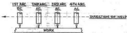
NOTE: THE THREE AC ARCS MUST BE PROPERLY PHASED RELATIVE TO EACH OTHER. IF THE ELECTRICAL CONNECTIONS ARE NOT AS SHOWN ABOVE, POOR WELDING WILL RESULT.
(A.) ONE WAY TO VERIFY PROPER PHASE ANGLE AND PHASE SEQUENCE IS TO USE AN OSCILLOSCOPE AS FOLLOWS:
1.) DO NOT WELD DURING THE FOLLOWING MEASUREMENTS. BACK THE ELECTRODE OUT OF THE DRIVE ROLLS. PRESS THE NA-4 START BUTTONS.
2.) EXTERNALLY TRIGGER THE SCOPE FROM THE VOLTAGE ON THE 4TH NOZZLE.
3.) CONNECT THE SCOPE INPUT TO EACH AC NOZZLE AND NOTE THE TIME OR PHASE DIFFERENCE BETWEEN ALL THREE. THEY SHOULD LOOK LIKE FIG.1.
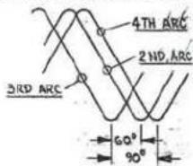
| PHASE ANGLE | 50 Hz TIME | 60 Hz TIME |
| 60° | 3.3 m sec. | 2.5 m sec |
| 90° | 5.0 m sec. | 4.2 m sec |
FIG.1
(B.) ANOTHER WAY TO VERIFY PROPER PHASE ANGLE AND PHASE SEQUENCE IS TO MEASURE THE AC VOLTAGES BETWEEN THE NOZZLES.
1) DO NOT WELD DURING THE FOLLOWING MEASUREMENTS. BACK THE ELECTRODE OUT OF THE DRIVE ROLLS. PRESS THE NA-4 START BUTTONS.
2.) THE VOLTAGE READINGS BETWEEN THE NOZZLES SHOULD BE PER THE TABLE BELOW.
| WELDER OCV2ND ARCNOTELE TO WORK | VOLTAGE BETWEEN2ND & 3RD ARCNOBELES | VOLTAGE BETWEEN3RD & 4TH ARCNOTELES | VOLTAGE BETWEEN2ND & 4TH ARCNOTELES |
| V | V | 1.41V | .52V |
| 90 | 90 | 127 | 47 |
IF THE VOLTAGE READINGS DO NOT AGREE, RE-CHECK ALL WIRING AND FOR PROPER PHASE SEQUENCE OF THE INPUT SUPPLY LINES.
N.A. REFER TO DC-1000 PARALLELING KIT (T14400). KIT CONTAINS CONTROL CABLE ASSEMBLY AND PARALLELING DIAGRAM INSTRUCTION SHEET. DIAGRAM SHOWS DETAILED INFORMATION FOR PARALLELING INPUTS, OUTPUTS AND CONTROL LEADS.
AC-1500 AND DC-1500's
DOUBLE TANDEM ARC WELDING
DC, AC, AC, AC (LAST TWO ARCS SCOTT CONNECTED)
FRAMES OF ALL WELDING POWER SOURCES MUST BE GROUNDED
PER NATIONAL ELECTRIC CODE.
PHASE SEQUENCE A-C-B
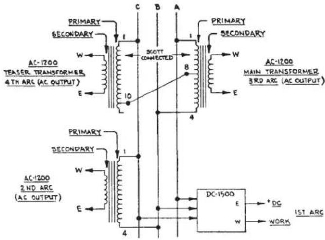
M-14364-1
4-8-83

NOTE: THE THREE AC ARCS MUST BE PROPERLY PHASED RELATIVE TO EACH OTHER, IF THE ELECTRICAL CONNECTIONS ARE NOT AS SHOWN ABOVE, POOR WEEDING WILL RESULT.
(A.) ONE WAY TO VERIFY PROPER PHASE ANGLE AND PHASE SEQUENCE IS TO USE AN OSCILLOSCOPE AS FOLLOWS:
1.) DO NOT WELD DURING THE FOLLOWING MEASUREMENTS. BACK THE ELECTRODE OUT OF THE DRIVE
ROLLS. PRESS THE NA-4 START BUTTONS.
2.) EXTERNALLY TRIGGER THE SCOPE FROM THE VOLTAGE ON THE 4TH NOZZLE.
3) CONNECT THE SCOPE INPUT TO EACH AC NOZZLE AND NOTE THE TIME OR PHASE DIFFERENCE BETWEEN ALL THREE. THEY SHOULD LOOK LIKE FIG.1.
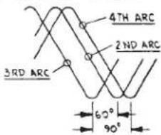
| PHASE ANGLE | 50 H2 TIME | 60 H2 TIME |
| 60° | 3.3 m sec. | 2.8 m sec. |
| 90° | 5.0 m sec. | 4.2 m sec. |
FIG. 1
(B.) ANOTHER WAY TO VERIFY PROPER PHASE ANGLE AND PHASE SEQUENCE IS TO MEASURE THE AC VOLTAGES BETWEEN THE NOZZLES.
1.) DO NOT WELD DURING THE FOLLOWING MEASUREMENTS. BACK THE ELECTRODE OUT OF THE DRIVE ROLLS. PRESS THE NA-4 START BUTTONS,
2.) THE VOLTAGE READINGS BETWEEN THE NOZZLES SHOULD BE PER THE TABLE BELOW.
| WELDER OCV2ND ARCNOZZLE TO WORK | VOLTAGEBETWEEN2ND & 3RD ARCNOZZLES | VOLTAGEBETWEEN3RD & 4TH ARCNOZZLES | VOLTAGEBETWEEN2ND & 4TH ARCNOZZLES |
| V | V | 1.41 V | .52 V |
| 90 | 90 | 127 | 47 |
IF THE VOLTAGE READINGS DO NOT AGREE, PE-CHECK ALL WIRING AND FOR PROPER PHASE SEQUENCE OF THE INPUT SUPPLY LINES.

 |  |  | 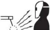 |
| WARNING | ·Do not touch electrically live parts or electrode with skin or wet clothing.·Insulate yourself from work and ground. | ·Keep flammable materials away. | ·Wear eye, ear and body protection. |
| SpanishAVISO DE PRECAUCION | ·No toque las partes o los electrodos bajo carga con la piel o ropa moja-da.·Aislese del trabajo y de la tierra. | ·Mantenga el material combustible fuera del área de trabajo. | ·Protéjase los ojos, los oídos y el cuerpo. |
| FrenchATTENTION | ·Ne laissez ni la peau ni des vête-ments mouillés entrer en contact avec des pièces sous tension.·Isolez-vous du travail et de la terre. | ·Gardez à l'écart de tout matériel inflammable. | ·Protégez vos yeux, vos oreilles et votre corps. |
| GermanWARNUNG | ·Berühren Sie keine stromführenden Teile oder Elektroden mit Ihrem Körper oder feuchter Kleidung!·Isolieren Sie sich von den Elektroden und dem Erdboden! | ·Entfernen Sie brennbarres Material! | ·Tragen Sie Augen-, Ohren- und Kör-perschutz! |
| PortugueseATENÇÃO | ·Não toque partes elétricas e electro-dos com a pele ou roupa molhada.·Isole-se da peça e terra. | ·Mantenha inflamáveis bem guarda-dos. | ·Use proteção para a vista, ouvido e corpo. |
| Japanese注意事項 | ●通電中の電気部品、又は溶材にヒフやぬれた布で触れないこと。●施工物やアースから身体が絶縁されている様にして下さい。 | ●燃えやすいものの側での溶接作業は絶対にしてはなりません。 | ●目、耳及び身体に保護具をして下さい。 |
| Chinese警告 | ●皮肤或濕衣物切勿接觸帶電部件及錚條。●使你自己與地面和工件絶縁。 | ●把一切易燃物品移離工作場所。 | ●佩戴眼、耳及身體勞動保護用具。 |
| Korean위험 | ●전도세나 응접봉을 젖은 형길 또는 피부로 절대 접촉치 마십시오.●모재와 접지를 접촉치 마십시오. | ●인화성 물질을 접근 시키지 마시요. | ●눈, 귀와 몇에 보호장구를 착용하십시오. |
| Arabicتحذير | ●لا تلمس الاجزاء التي يسري فيها التيار الكهرباني أو الاكترود بجلد الجسم أو بالعلابس المبلقة بال permاء.●ضع عازلا على جسمك خلال العمل. | ●ضع #: ● ضع #: ● ضع: ● ضع: ● ضع: ● ضع: ● ضع: ● ضع: ● ضع: ● ضع: ● ضع: ● ضع: ● ضع: ● ضع: ● ضع: ● ضع: ● ضع: ● ضع: ● ضع: ● ضع: ● ضع: ● ضع: ● ضع: ● ضع: ● ضع: ● ضع: ● ضع: ● ضع; ● ضع: ● ضع: ● ضع: ● ضع: ● ضع: ● ضع: ● ضع: ● ضع: ● ضع: ● ضع: ● ضع: ● ضع: ● ضع: ● ضع: ● ضع: ● ضع: ● ضع: ● ضع: ● ضع: ● ضع: ● ضع: ● ضع: ● ضع: ● ضع: ● ضع, ● ضع: ● ضع: ● ضع: ● ضع: ● ضع: ● ضع: ● ضع: ● ضع: ● ضع: ● ضع: ● ضع: ● ضع: ● ضع: ● ضع: ● ضع: ● ضع: ● ضع: ● ضع: ● ضع: ● ضع: ● ضع: ● ضع: ● ضع: ● ضع: ● ضع : ● ضع : ● ضع : ● ضع : ● ضع : ● ضع : ● ضع : ● ضع : ● ضع : ● ضع : ● ضع : ● ضع : ● ضع : ● ضع : ● ضع : ● ضع : ● ضع : ● ضع : ● ضع : ● ضع : ● ضع : ● ضع : ● ضع : ● ضع : ● ضع : ● ضع: ● ضع: ● ضع: ● ضع: ● ضع: ● ضع: ● ضع: ● ضع: ● ضع: ● ضع: ● ضع: ● ضع: ● ضع: ● ضع: ● ضع: ● ضع: ● ضع: ● ضع: ● ضع: ● ضع: ● ضع: ● ضع: ● ضع: ● ضع: ● ضع | |
READ AND UNDERSTAND THE MANUFACTURER'S INSTRUCTION FOR THIS EQUIPMENT AND THE CONSUMABLES TO BE USED AND FOLLOW YOUR EMPLOYER'S SAFETY PRACTICES.
- WARNING
- CALIFORNIA PROPOSITION 65 WARNINGS
- FOR ENGINE POWERED EQUIPMENT
- ELECTRIC AND MAGNETIC FIELDS MAY BE DANGEROUS
- ELECTRIC SHOCK CAN KILL
- ARC RAYS CAN BURN
- FUMES AND GASES CAN BE DANGEROUS
- WELDING AND CUTTING SPARKS CAN CAUSE FIRE OR EXPLOSION
- CYLINDER MAY EXPLODE IF DAMAGED
- FOR ELECTRICALLY POWERED EQUIPMENT
- PRÉCAUTIONS DE SÛRETÉ
- CUSTOMER ASSISTANCE POLICY
- PLEASE EXAMINE CARTON AND EQUIPMENT FOR DAMAGE IMMEDIATELY
- ON-LINE PRODUCT REGISTRATION
- CAUTION
- INSTALLATION......SECTION A
- OPERATION......SECTION B
- ACCESSORIES......SECTION C
- MAINTENANCE ....SECTION D
- TROUBLESHOOTING......SECTION E
- WIRING DIAGRAMS AND DIMENSION PRINT......SECTION F
- LOCATION
- INPUT WIRING
- ELECTRIC SHOCK
- OUTPUT CONNECTIONS
- WIRE FEEDER CONNECTION
- CONNECTION OF AC-1500 TO NA-4 WITH RHEOSTAT FOR CURRENT CONTROL
- OUTPUT STUDS
- AUXILIARY POWER
- DUTY CYCLE
- SAFETY PRECAUTIONS
- WELDING SPARKS CAN CAUSE FIRE OR EXPLOSION
- GRAPHIC SYMBOLS THAT APPEAR ON THIS MACHINE OR IN THIS MANUAL
- PRODUCT DESIGN APPLICATION
- SETTING THE MACHINE OUTPUT OR REMOTE CONTROL
- SETTING THE OUTPUT CURRENT
- PRODUCT DESCRIPTION
- SEE ADDITIONAL WARNING INFORMATION THROUGHOUT THIS OPERATOR'S MANUAL
- HOW TO USE TROUBLESHOOTING GUIDE
- STEP 1. LOCATE PROBLEM (SYMPTOM)
- STEP 2. POSSIBLE CAUSE
- STEP 3. RECOMMENDED COURSE OF ACTION
- AC-1500 SCOTT CONNECTION DIAGRAM
- AC-1500 AND PARALLELED DC-1000'S
- AC-1500 AND DC-1500'S
- DOUBLE TANDEM ARC WELDING
Brand : LINCOLN ELECTRIC
Model : IDEALARC AC1500
Category : Welding machine