
RM-500 - Microphone TOA - Free user manual and instructions
Find the device manual for free RM-500 TOA in PDF.


| Product Type | Dynamic Handheld Microphone |
| Model | RM-500 |
| Brand | TOA |
| Polar Pattern | Cardioid |
| Frequency Response | 80 Hz – 15 kHz |
| Impedance | 600 ohms |
| Sensitivity | -72 dB (0 dB = 1 V/Pa, 1 kHz) |
| Connector | XLR-3-11C (balanced) |
| Power Supply | Phantom power 6–52 V DC |
| Dimensions (approx.) | 180 mm (length), 50 mm (diameter) |
| Weight (approx.) | 300 g (without cable) |
| Cable Length | 5 m (integrated) |
| Housing Material | Die-cast zinc alloy |
| Finish | Matte black |
| Primary Functions | Public address, speech reinforcement, paging |
| Maintenance | Wipe with a dry soft cloth; avoid moisture and solvents |
| Cleaning | Use a soft brush for the grille; do not use compressed air |
| Safety Precautions | Do not drop or expose to excessive vibration |
| Spare Parts | Grille cap replacement available |
| Repair | Contact TOA authorized service center |
Frequently Asked Questions - RM-500 TOA
User questions about RM-500 TOA
0 question about this device. Answer the ones you know or ask your own.
Ask a new question about this device
Download the instructions for your Microphone in PDF format for free! Find your manual RM-500 - TOA and take your electronic device back in hand. On this page are published all the documents necessary for the use of your device. RM-500 by TOA.
USER MANUAL RM-500 TOA
Thank you for purchasing TOA's Remote Microphone.
Please carefully follow the instructions in this manual to ensure long, trouble-free use of your equipment.

natural_image
Line drawing of a handheld electronic device with a microphone and display panel (no text or symbols)TABLE OF CONTENTS
- SAFETY PRECAUTIONS ...... 2
- GENERAL DESCRIPTION 3
- FEATURES .... 3
- NOMENCLATURE 4
- LCD SCREEN DISPLAY .... 5
- OPERATION 6
6.1. Making an Individual (Group) Zone Broadcast 6
6.2. Making All-Zone Broadcast 7
- EXPLANATION OF SYMBOLS 7
- SPECIFICATIONS 8
1. SAFETY PRECAUTIONS
- Before installation or use, be sure to carefully read all the instructions in this section for correct and safe operation.
- Be sure to follow all the precautionary instructions in this section, which contain important warnings and/or cautions regarding safety.
• After reading, keep this manual handy for future reference.

WARNING
Indicates a potentially hazardous situation which, if mishandled, could result in death or serious personal injury.

CAUTION
Indicates a potentially hazardous situation which, if mishandled, could result in moderate or minor personal injury, and/or property damage.

WARNING
When Installing the Unit
- Do not expose the unit to rain or an environment where it may be splashed by water or other liquids, as doing so may result in fire or electric shock.
- Use the unit only with the voltage specified on the unit. Using a voltage higher than that which is specified may result in fire or electric shock.
- Avoid installing or mounting the unit in unstable locations, such as on a rickety table or a slanted surface. Doing so may result in the unit falling down and causing personal injury and/or property damage.
- Since the unit is designed for indoor use, do not install it outdoors. If installed outdoors, the aging of parts causes the unit to fall off, resulting in personal injury. Also, when it gets wet with rain, there is a danger of electric shock.
When the Unit is in Use
- To prevent a fire or electric shock, never open nor remove the unit case as there are high voltage components inside the unit. Refer all servicing to qualified service personnel.
- Do not place cups, bowls, or other containers of liquid or metallic objects on top of the unit. If they accidentally spill into the unit, this may cause a fire or electric shock.
- Do not insert nor drop metallic objects or flammable materials in the ventilation slots of the unit's bottom surface, as this may result in fire or electric shock.

CAUTION
When Installing the Unit
- Avoid installing the unit in humid or dusty locations, in locations exposed to the direct sunlight, near the heaters, or in locations generating sooty smoke or steam as doing otherwise may result in fire or electric shock.
- Use the dedicated AC adapter for the unit. Note that the use of other adapter may cause a fire.
2. GENERAL DESCRIPTION
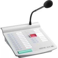
The RM-500 is a desktop type remote microphone for general broadcasts designed to be connected to the VX-3000 Series Integrated Voice Evacuation System.
3. FEATURES
- The names of arbitrary zones and groups can be displayed on the LCD screen as the broadcast destinations. In addition, visible and comprehensive icons are adopted for the broadcast status display.
- Can make broadcasts to up to 80 pre-registered zones by the key operation.
- The AUX key allows only the external audio signals to be controlled regardless of whether the microphone announcements are present or not.
- The speech intelligibility function makes it easier to hear the microphone announcements even in noisy environments, and also allows the microphone to pick up the audio signals at an appropriate level even if speaking too close to or too far from it.
- Equipped with the control output terminals, allowing the external unit such as sound source equipment to be activated from the own unit.
- Equipped with the control input terminals, allowing an arbitrary broadcast to be activated.
- Can be mounted on the wall by using an optional wall mounting bracket.
4. NOMENCLATURE
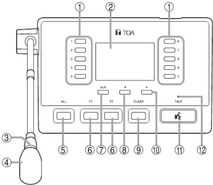
1. Numeric keys
Normally, select the item number displayed on the LCD screen. The functions set with the VX-3000 Setting software can be executed.
2. LCD screen
Normally, displays a list of the set functions and the status of the broadcast or function.
3. Microphone indicator (green)
Lights during the microphone broadcasts.
However, it does not light when announcements are being broadcast from the microphone connected to the AUX input terminal.
You can also set it to OFF by the system setting.
4. Microphone
Used for making general broadcasts.
5. ALL key
Selects the preset zones.
6. F1/F2 key
The functions set with the VX-3000 Setting software can be executed.
7. AUX key
Press this key to broadcast the audio signals fed to the AUX input terminal.
8. ◀ key
Press this key to move to the previous page from the current page displayed on the LCD screen.
9. Clear key
Terminates the broadcast when pressed while broadcast is in progress.
Clears selection for all the zones being selected.
10.▶ key
Press this key to move to the next page from the current page displayed on the LCD screen.
11. Talk key
Press this key to broadcast a voice announcement.
Set the key operation mode to either PTT or Lock at the system setup.
If the Talk key is set to "PTT" ("press-to-talk") mode, then it must be pressed continuously for the duration of the broadcast.
If the Talk key is set to "Lock" mode, then it must be pressed once to turn the microphone on at the beginning of a broadcast, then pressed again to turn the microphone off once the broadcast is finished.
12. Talk indicator (green)
Lights or goes off depending on the current operation state of the Talk key.
5. LCD SCREEN DISPLAY
In normal use state, the following contents are displayed on the LCD screen.
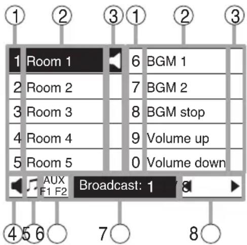
1. Number
Displays the number corresponding to the numeric key.
2. Function display area
Displays the function name.
3. Individual icon display area
Displays the state of the function corresponding to the number by an icon.
4. Overall icon display area
Displays the icon that represents the state of the function with the highest display priority in the statuses of all functions assigned to this unit.
5. Chime display area
Displays the chime icon (♪) when the chime is sounding by this unit's operation.
6. AUX/Function display area
Displays the function of the AUX key and the state of the F1/F2 key.
| AUX key | F1/F2 key | ||
| When the key is turned ON | AUX F | F2 | |
| When the key is turned OFF | AUX F1 | F2 | |
7. Broadcast status display area
Displays the broadcast status of the whole function assigned to this unit.
8. Page display
Displays the current page/total page.
[Icon display list]
| Icon Name | Display priority level | Meaning of icon | |
 | Emergency broadcast in progress | High | Emergency broadcast is in progress. |
 | Broadcast from another unit in progress | Broadcast from another unit is in progress. | |
 | Broadcast in progress | Low | Microphone announcements or AUX broadcast is in progress from this unit, or zones are being selected (including the broadcast after zone selection is in progress). Simultaneously check the display in the broadcast status display area (7). |
 | Control input in operation | Indicates that the control input of this unit is in make state. This icon is dedicated for the overall icon display area (4). | |
 | Others in operation | - | Displayed only in the Individual icon display area (3). The function assigned to the function display on the LCD screen is operating. |
6. OPERATION
- Operation method of the Talk key ( ) depends on the settings.
When the Talk key is set to PTT type, make microphone announcements while pressing the Talk key.
When the Talk key is set to Lock type, press the key once, then release it to start microphone announcements.
- If the icon (◀) "Broadcast from another unit in progress" is displayed on the LCD screen and not changed to (◀) "Broadcast in progress," this is an indication that the broadcast is being made from another unit having higher priority.
In this case, you cannot make broadcast from the own unit.
- To make broadcasts using the external equipment, press the AUX key.
6.1. Making an Individual (Group) Zone Broadcast

Step 1. Press the ◀ or ▶ key several times to display the page containing the target item to select.
Step 2. Press the numeric key corresponding to the number of the item to select.
Tip
To cancel the selection individually, press the numeric key corresponding to the number of the selected item again.
Step 3. To continue selecting, repeat Steps 1 and 2 as many times as necessary.
Step 4. Press the Talk key to start microphone announcements.
Step 5. Terminate the microphone broadcast by pressing the Talk key or the Clear key.
6.2. Making All-Zone Broadcast
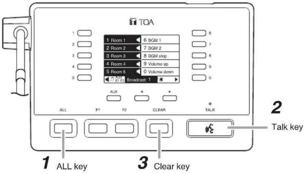
Step 1. Press the ALL key.
Step 2. Press the Talk key to start microphone announcements.
Step 3. Terminate the microphone broadcast by pressing the Talk key or the Clear key.
7. EXPLANATION OF SYMBOLS
| Symbol | Position Explanation |
 | Front This mark is an indication that the key with this mark is used for microphone announcements. |
 | Left side Volume control: turn it clockwise with a screw driver to increase the volume, turn it counter-clockwise to decrease the volume. |
 | Bottom Do not trash this device into normal waste.Use the foreseen electric waste collection places. |
 | This mark is a declaration that this product complies with all applicable EU directive and regulations. |
 | This mark is a declaration that this product complies with all requirements under UK regulations. |
 | This mark is a declaration that this product complies with all applicable China RoHS and regulations. |
 | Shows the polarity of the AC Adapter socket.The center pin is positive and its surrounding surface is negative. |
 | Shows the system's power voltage (24 V DC). |
8. SPECIFICATIONS
| Power Source 24 V DC | (operating range: 15 – 33 V DC)Supplied from the applicable system (RJ45 connector)or the optional AD-246 AC adapter (DC input power supply connector)Usable DC power supply plug: 5.5 mm (0.22") outer diameter,2.1 mm (0.08") inner diameter,9.5 mm (0.37") long, polarized, center positive |
| Current Consumption 130 mA or less | |
| Audio Output 0 dB*, balanced, RJ45 connector | |
| AUX Input 1 channel, un | balanced, LINE/MIC (selectable with the DIP switch)LINE: -20 dB*, 10 kΩ, push-in terminal blockMIC: -60 dB*, 2.2 kΩ, push-in terminal block |
| Control Input 1 channel, | no-voltage make contact inputs, open voltage: 33 V DC,short-circuit current: 10 mA, push-in terminal block |
| Control Output 1 channel, | open collector output, withstand voltage: 30 V DC,control current: 35 mA, push-in terminal block |
| Distortion 1% or less | |
| Frequency Response 100 Hz to 20 kHz | |
| Signal to Noise Ratio 60 | dB or more |
| Microphone | Unidirectional electret condenser microphone |
| Chime | Uses the built-in sound sources of the main system unit(one of them selectable by the main system settings) |
| Level Control | Microphone volume control, AUX volume control |
| RM Link | Shielded Category 5 twisted pair LAN cable (CAT5-STP), RJ45 connectorMaximum cable distance: 1200 m (3937.01 ft)(when powered by the optional AD-246 AC adapter) |
| External Equipment Connection Cable | Solid copper wire: ø0.4 – ø1.1 mm (AWG 28 – 17) |
| Operation | Numeric key x 10, Left/right selection key x 2, F1/F2 key x 2, ALL key x 1, Clear key x 1, Talk key x 1, AUX key x 1 |
| Indicator | LCD display: 3" (255 x 160 dots), with backlightIndicator: Talk indicator (green), Microphone indicator (green) |
| Operating Temperature | 0 to 40 °C (32 to 104 °F) |
| Operating Humidity | 90% RH or less (no condensation) |
| Finish | ABS resin, black, paint |
| Dimensions | 224 (w) x 47.2 (h) x 136 (d) mm (8.82" x 1.86" x 5.35") (excluding microphone) |
| Weight | 620 g (1.37 lb) |
| Accessories | Zip tie .... 2 |
| Optional Products | Wall mounting bracket: WB-RM500AC adapter: AD-246 |
* 0 dB = 1 V
Note: The design and specifications are subject to change without notice for improvement.
Traceability Information for Europe
| Manufacturer: |
| TOA Corporation |
| 7-2-1, Minatojima-Nakamachi, Chuo-ku, Kobe, Hyogo, Japan |
| Authorized representative: |
| TOA Electronics Europe GmbH |
| Suederstrasse 282, 20537 Hamburg, Germany |

- TABLE OF CONTENTS
- SAFETY PRECAUTIONS
- WARNING
- CAUTION
- When Installing the Unit
- When the Unit is in Use
- GENERAL DESCRIPTION
- FEATURES
- NOMENCLATURE
- Numeric keys
- LCD screen
- Microphone indicator (green)
- Microphone
- ALL key
- F1/F2 key
- AUX key
- ◀ key
- Clear key
- 10.▶ key
- Talk key
- Talk indicator (green)
- LCD SCREEN DISPLAY
- Number
- Function display area
- Individual icon display area
- Overall icon display area
- Chime display area
- AUX/Function display area
- Broadcast status display area
- Page display
- OPERATION
- Making an Individual (Group) Zone Broadcast
- Making All-Zone Broadcast
- EXPLANATION OF SYMBOLS
- SPECIFICATIONS
Brand : TOA
Model : RM-500
Category : Microphone