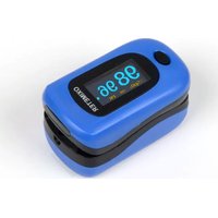
OXY-4 - Measuring equipment GIMA - Free user manual and instructions
Find the device manual for free OXY-4 GIMA in PDF.


| Product Type | Pulse Oximeter |
| Model | OXY-4 |
| Brand | GIMA |
| Dimensions | Approx. 58 x 36 x 32 mm |
| Weight (with batteries) | Approx. 50 g |
| Power Supply | 2 x AA alkaline batteries (1.5 V) |
| Battery Life | Approx. 30 hours continuous use |
| Display | LED digital display (SpO2, pulse rate, bar graph) |
| Measurement Parameters | SpO2 (0-100%), Pulse Rate (30-250 bpm) |
| Accuracy (SpO2) | ±2% (70-100%), unspecified below 70% |
| Accuracy (Pulse Rate) | ±2 bpm |
| Auto Power Off | Yes, after 8 seconds without signal |
| Low Battery Indicator | Yes, displayed on screen |
| Audible Alarm | Not available |
| Data Storage | None |
| Compatible Finger Size | Adults: circumference 2.2-3.2 cm |
| Operating Temperature | 10°C to 40°C |
| Storage Temperature | -20°C to 60°C |
| Standards Compliance | CE, FDA (if applicable), ISO 80601-2-61 |
| Maintenance & Cleaning | Wipe with 70% isopropyl alcohol; do not immerse |
| Safety Precautions | Not for continuous monitoring; avoid MRI; keep away from children |
| Spare Parts / Repairability | Replacement batteries, lanyard; no user-serviceable parts inside |
Frequently Asked Questions - OXY-4 GIMA
User questions about OXY-4 GIMA
0 question about this device. Answer the ones you know or ask your own.
Ask a new question about this device
Download the instructions for your Measuring equipment in PDF format for free! Find your manual OXY-4 - GIMA and take your electronic device back in hand. On this page are published all the documents necessary for the use of your device. OXY-4 by GIMA.
USER MANUAL OXY-4 GIMA
PULSOXIMETRO OXY-4 OXY-4 PULSE OXIMETER OXYMÈTRE OXY-4 PULOXIMETER OXY-4 OXÍMETRO OXY-4 OXÍMETRO DE PULSO OXY-4 KOPEŠTOMETPO OXY-4 OKSYMETR OXY-4
MANUALE D'USO E MANUTENZIONE
USE AND MAINTENANCE BOOK
INSTRUCTIONS DE FONCIONNEMENT ET ENTRETIEN
ATTENTION: The operators must carefully read and completely understand the present manual before using the product.
20060 Gessate (MI) - Italy
Made in China


0476





Instructions to User
Read these instructions carefully before using this equipment. These instructions describe the operating procedures to be followed strictly. Failure to follow these instructions can cause measuring abnormality, equipment damage and personal injury. The manufacturer is NOT responsible for the safety, reliability and performance issues and any monitoring abnormality, personal injury and equipment damage due to user's negligence of the operation instructions. The manufacturer's warranty service does not cover such faults.
- The contents contained in this manual are subject to change without notice.
- The uncomfortable or painful feeling may appear if using the device ceaselessly, especially for the microcirculation barrier patients. It is recommended that the sensor should not be applied to the same finger for over 2 hours- If any abnormal condition is found, please change the position of Pulse Oximeter.
- For the individual patients, there should be a more prudent inspecting in the placing process. The device can not be clipped on the edema and tender tissue.
- The light (the infrared is invisible) emitted from the device is harmful to the eyes, so the user and the maintenance man, can not stare at the light. - The Pulse Oximeter is not a treatment device.
- Testee can not use enamel or other makeup on the hinge.
- Testee's fingernail can not be too long- Please peruse the relative content about the clinical restrictions and caution.
1. SAFETY
1.1 Instructions for Safe Operations
- Check the main unit and all accessories periodically to make sure that there is no visible damage that may affect patient's safety and monitoring performance with regard to sensors and clips. It is recommended that the device should be inspected minimally before each use. When there is obvious damage, stop using the oximeter.
- Necessary maintenance must be performed by qualified service technicians ONLY. Users are not permitted to maintain it by themselves.
- The oximeter cannot be used together with the devices and accessories not specified in Use's Manual.
- Special attention should be paid while the Pulse Oximeter is used constantly when the ambient temperature over 37^ C, burning hurt may occur because of over-heating of the sensor at this situation.
1.2 Attentions

- Keep the oximeter away from dust, vibration, corrosive substances, explosive materials, high temperature and moisture.
- The device should be kept out of the reach of children.
- If the oximeter gets wet, please stop using it and do not resume operation until it is dry and checked for correct operation. When it is carried from cold environment to warm and humid environment, please do not use it immediately. Allow at least 15 minutes for Pulse Oximeter to reach ambient temperature.
- DO NOT press the keys on front panel with sharp materials or sharp points.
- High temperature or high pressure steam disinfection to the oximeter is not permitted. Refer to User's Manual for instructions of cleaning and disinfection.
- The finger should be put in properly and correctly.
- Do not shake the finger. Keep at ease during measurement.
- Do not put wet finger directly into sensor.
- Do not let anything block the emitting light from the device.
- Ensure that there is artery vessel within measuring site where the light transmits through.
- Vigorous exercise and the interference from the electrosurgical device may affect the measuring accuracy.
- If the first reading appears with poor waveform (irregular or not smooth), then the reading is unlikely true, the more stable value is expected by waiting for a while, or a restart is needed when necessary.
2. OVERVIEW
SpO2 is the saturation percentage of oxygen in the blood, so called O2 concentration in the blood; it is defined by the percentage of oxyhemo-
globin (HbO 2 ) in the total hemoglobin of the arterial blood. SpO 2 is an important physiological parameter to reflect the respiration function; it is calculated by the following method:
$$ \mathrm{SpO} _ {2} = \mathrm{HbO} _ {2} / (\mathrm{HbO} _ {2} + \mathrm{Hb}) \times 100 \% $$
HbO _2 are the oxyhemoglobins (oxygenized hemoglobin), Hb are those hemoglobins which release oxygen.
2.1 Features
- Large true color OLED display of SpO_2 , PR Pulse Bar, PI & Plethysmogram.
- Innovative 4 directions display.
- Automatic power on/off.
- Audible & visible over-limit indication.
- Shift parameter display between PR and PI.
2AAA alkaline batteries with low power consumption. - Low battery voltage indication.
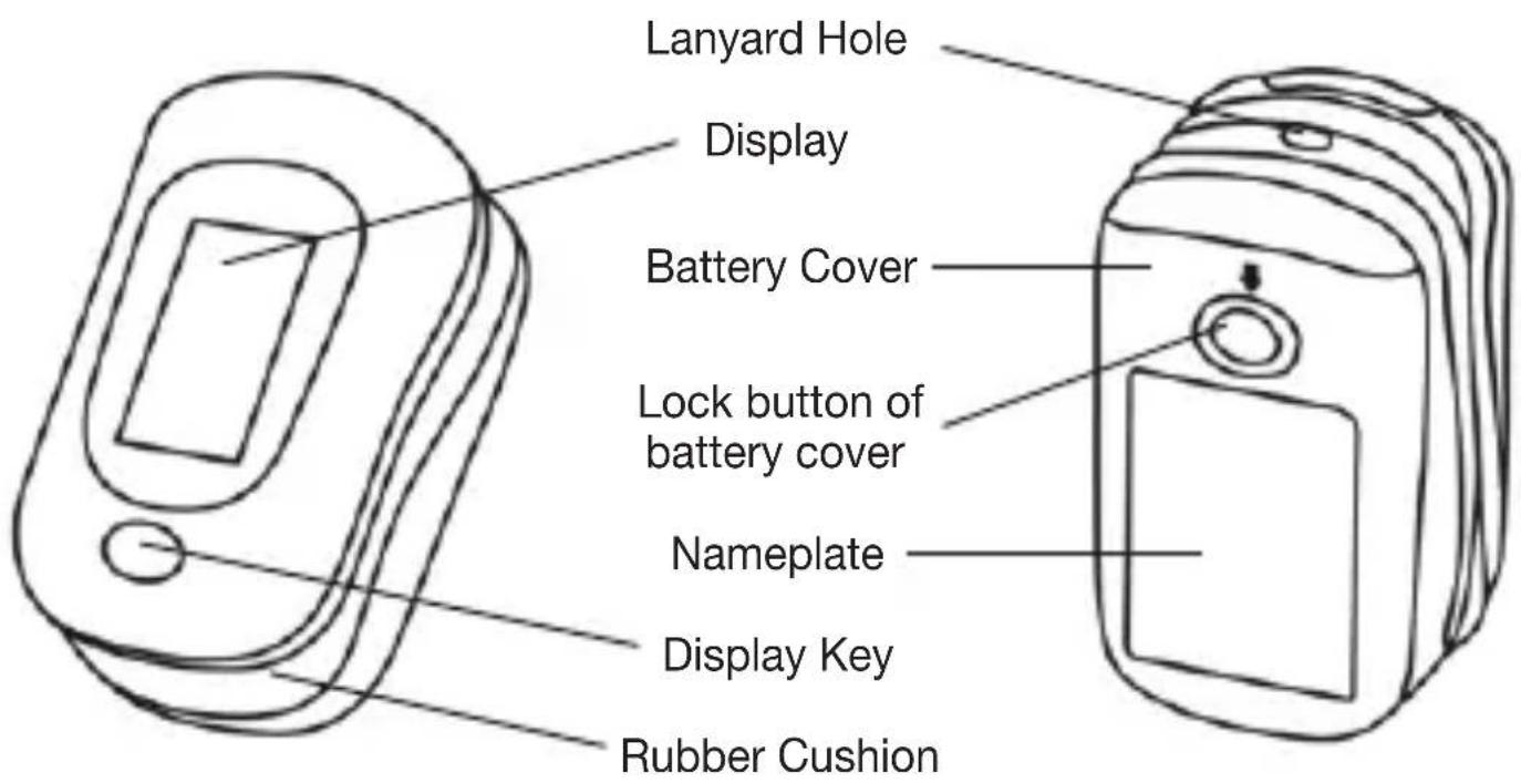
Figure 1
2.2 Major Applications and Scope
The Fingertip Oximeter is compact, convenient to use and carry and with low power consumption. You just need to put the fingertip into the sensor of the device, the SpO_2 value will appear on the screen immediately.
The Fingertip Oximeter can detect SpO_2 and pulse rate through patient's finger.
This device is applicable to home, hospital (including internal medicine, surgery, anesthesia, pediatrics, emergency room etc.), oxygen bar, the community medical center, alpine area and it also can be used before or after sports, and the like.

This device is not appropriate to be used for continuous monitoring.
2.3 Principle of Measurement
Based on Lamber-Beer law, the light absorbance of a given substance is directly proportional with its density or concentration. When the light with certain wavelength emits on human tissue, the measured intensity of light after absorption, reflecting and attenuation in tissue can reflect the structure character of the tissue by which the light passes. Due to that oxygenated hemoglobin (HbO 2 ) and deoxygenated hemoglobin (Hb) have different absorption character in the spectrum range from red to infrared light (600nm\~1000nm wavelength), by using these characteristics, SpO 2 can be determined. SpO _2 measured by this Pulse Oximeter is the functional oxygen saturation -- a percentage of the hemoglobin that can transport oxygen. In contrast, hemoximeters report fractional oxygen saturation – a percentage of all measured hemoglobin, including dysfunctional hemoglobin, such as carboxyhemoglobin or metahemoglobin.
Clinical application of pulse oximeters: SpO_2 is an important physiological parameter to reflect the respiration and ventilation function, so SpO_2 monitoring used in treatment has become more popular. (For example, such as monitoring patients with serious respiratory disease, patients under anesthesia during operation and premature and neonatal infants) The status of SpO_2 can be determined in timely manner
by measurement and will allow finding the hypoxemia patient earlier, thereby preventing or reducing accidental death caused by hypoxia effectively.
Factors affecting SpO2 measuring accuracy (interference reason)
- Intravascular dyes such as indocyanine green or methylene blue.
- Exposure to excessive illumination, such as surgical lamps, bilirubin lamps, fluorescent lights, infrared heating lamps, or direct sunlight.
- Vascular dyes or external used color-up product such as nail enamel or color skin care.
- Excessive patient movement.
- Placement of a sensor on an extremity with a blood pressure cuff, arterial catheter, or intravascular line.
- Exposure to the chamber with High pressure oxygen.
- There is an arterial occlusion proximal to the sensor.
- Blood vessel contraction caused by peripheral vessel hyperkinesias or body temperature decreasing.
Factors causing low SpO_2 Measuring value (pathology reason)
- Hypoxemia disease, functional lack of HbO_2 .
- Pigmentation or abnormal oxyhemoglobin level.
- Abnormal oxyhemoglobin variation.
- Methemoglobin disease.
- Sulfhemoglobinemia or arterial occlusion exists near sensor.
- Obvious venous pulsations.
- Peripheral arterial pulsation becomes weak.
- Peripheral blood supply is not enough.
2.4 Caution
A. The finger should be placed properly (see the figure 3 of this manual), or else it may cause inaccurate measurement.
B. The SpO_2 sensor and photoelectric receiving tube should be arranged in a way with the subject's arteriole in a position there between.
C. The SpO_2 sensor should not be used at a location or limb tied with
arterial canal or blood pressure cuff or receiving intravenous injection.
D. Do not fix the SpO_2 sensor with adhesive or else it may result in venous pulsation and inaccurate measure of SpO_2 .
E. Make sure the optical path is free from any optical obstacles like rubberized fabric.
F. Excessive ambient light may affect the measuring result. It includes fluorescent lamp, dual ruby light, infrared heater, direct sunlight and etc.
G. Strenuous action of the subject or extreme electrosurgical interference may also affect the accuracy.
3. BATTERY INSTALLATION
- Press the lock button of the battery cover, meanwhile, pull the cover back and take it out.
- Refer to Figure 2, insert two AAA size batteries into the battery compartment properly.
- Replace the cover. Please make sure that the batteries are correctly installed since the incorrect installation may cause the device inoperable.

natural_image
Line drawing of a mobile phone casing with open lid and internal components, showing two cylindrical parts (no text or symbols)Figure 2 Battery Installation
4. OPERATION
4.1 Start Measurement
- Open the clip as shown in Figure 3.
- Put finger into the rubber cushions of the clip (make sure the finger is in the correct position), and then clip the finger.
- The device will power on automatically in 2 seconds, and start to display software version number.
- Next enter into data display screen (as shown in Figure 4). The user can read the values and view the waveform from display screen.

Figure 3 Put finger into the Oximeter


Figure 4 A1 Figure 4 A2 Figure 4 B1 Figure 4 B2


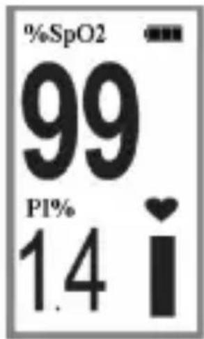
Figure 4 C1 Figure 4 C2 Figure 4 D1 Figure 4 D2
Screen Description:
“%SpO 2 ”: The title of SpO 2 ; “99”: SpO _2 value, unit:%;
"PR": The title of Pulse Rate; "65": Pulse Rate value, unit: bpm (beat per minute);
“♥. Pulse beat icon;
“”: Pulse bar-graph;
“PI%”: The title of Perfusion Index; “1.4”: Perfusion Index value, unit: %;;
"Battery power indicator.
- Change display direction
Four directions display alternately. Short time press “Display Key” to flip the screen 90° each time in a cyclical manner as shown in Figure 4. When the screen displays towards the left side, the plethysmogram will be viewed.
- Shift parameter display between PR and PI during measurement Long time press the “Display Key”, shift the parameter display between PR and PI. But when the PR is shifted to PI display and no button operation is performed after 20 seconds, the PI will change to PR display automatically.
4.2 Over-limit indication and Beep Silence
When measuring, if SpO_2 value or pulse rate value exceeds the limit, the device will beep automatically and the value which exceeds its limit will flash on the screen (Refer to chapter 4 for the detailed information).
When the beep sound is activated by over-limit, it will become silent or d-active at the following situations:
- The SpO_2 and PR value return to normal range.
- Press Display Key to mute. If this over-limit event persists, the Pulse Oximeter will resume beeping automatically later in 2 minutes.
- Remove the finger from the Pulse Oximeter or SpO_2 probe.
5. TECHNICAL SPECIFICATIONS
A. SpO_2 measurement:
dual-wavelength LED sensor with wavelength: Red light: 663 nm, Infrared light: 890 nm. Maximal average optical output power: ≤1.5mW Measuring range: 35%\~100% Measuring accuracy: ≤3% for SpO 2 range from 70% to 100% SpO 2 low over-limit: 90%
B. Pulse Rate measurement:
Measuring range: 30bpm\~240bpm Measuring accuracy: ±2bpm or ±2% (whichever is greater) Pulse Rate over-limit: high over-limit: 120bpm; low over-limit: 50bpm
C. Perfusion Index (PI) Display
Range: 0.2%\~20%
D. Audible & visual over-limit indication
When measuring, if SpO _2 value or pulse rate value exceeds the limit, the device will beep automatically and the value which exceeds its limit will flash on the screen. The Oximeter will shut down automatically in 8 seconds with no signal.
E. Display: Color OLED Display
F. Power supply requirement:
2 x LR03 (AAA) alkaline batteries Working voltage: 2.2V\~3.3VDC Operating current: ≤40mA
G. Environment requirement
Operating Temperature: 5 \~40°C
Operating Humidity: 30\~80%
Atmospheric pressure: 70\~106kPa
H. The performance under low perfusion condition
The accuracy of SpO _2 and PR measurement still meets the specification described above when the pulse modulation amplitude is as low as 0.6%.
I. Resistance to ambient light interference:
The accuracy of SpO_2 and PR measurement still meets the specification described above when the device is tested by SpO_2 simulator (Fluke Biomedical Index 2 series) while setting the emulating interference of sun light and 50Hz / 60Hz fluorescent light.
J. Dimensions: 60 mm (L) × 33 mm (W) × 30 mm (H)
Net Weight: 35g (including battery)
K. Classification:
The type of protection against electric shock: Internally powered equipment.
The degree of protection against electric shock: Type BF applied parts.
The degree of protection against harmful ingress of liquids: Ordinary equipment without protection against ingress of water.
Electro-Magnetic Compatibility: Group I, Class B.
6. ACCESSORIES
A. A lanyard
B. Two batteries
C. A carrying pouch
D. A User Manual

Note: The accessories are subject to change. Detailed items and quantity see the Packing List.
7. REPAIR AND MAINTENANCE
The expected service life (not a warranty) of this device is 5 years. In order to ensure its long service life, please pay attention to the use of maintenance.
A. Please change the batteries when the low-voltage indicator lightens.
B. Please clean the surface of the device before using. Wipe the device with 75% alcohol wipes, and then let it dry in air or wipe it dry. Do not allow liquid to enter the device.
C. Please take out the batteries if the oximeter will not be used for for any more than 7 days.
D. The recommended storage environment of the device is -20^ to 60^ ambient temperature and 10% to 95% relative humidity with atmospheric pressure: 50kPa 107.4kPa .
E. The Pulse Oximeter is calibrated in the factory before sale, so there is no need to calibrate it during its life cycle. However, if it is necessary to verify its precision routinely, the user can do the verification by means of SpO_2 simulator, or it can be done by the local third party testing house.
7.1 Cleaning and Disinfecting Instruction
Surface-clean sensor with a soft cloth damped with a solution such as 75% isopropyl alcohol, if low-level disinfection is required, use a mild bleach solution.
Then surface-clean by soft cloth damped ONLY with clean water and let air dry or wipe it dry.
Caution: Do not sterilize by irradiation steam, or ethylene oxide.
Do not use the Pulse Oximeter if it is damaged visually

High-pressure sterilization cannot be used on the device.
Do not immerse the device in liquid.
It is recommended that the device should be kept in a dry environment
8. TROUBLESHOOTING
| Trouble Possible Reason Solution | ||
| The SpO2and Pulse Rate display instable | 1. The finger is not placed far enough inside.2. The finger is shaking or the patient is moving. | 1. Place the finger correctly inside and try again.2. Let the patient keep calm. |
| Cannot turn on the device | 1. The batteries are drained or almost drained.2. The batteries are not inserted properly.3. The device is malfunctioning. | 1. Change batteries.2. Reinstall batteries.3. Please contact the local service center. |
| No display | 1. The device will power off automatically when it gets no signal for 8 s.2. The batteries are almost drained. | 1. Normal.2. Change batteries. |
Declaration of Conformity:
The manufacturer hereby declares that this device complies with the following standards:
IEC 60601-1
IEC60601-1-2
IEC60601-1-11, ISO 80601-2-61 and follows the provisions of the council directive MDD93/42/EEC.
9. KEY OF SYMBOLS
| Symbol | Description Symbol Description | ||
 | Type BF applied part WEE  sposal sposal | ||
 | Caution: read instructions (warnings) carefully |  | Keep away from sunlight |
 | Follow instructions for use |  | Keep in a cool, dry place |
 | Oxygen saturation (percentage) |  | Medical Device complies with Directive 93/42/EEC |
| PR | Pulse rate (beats per minute) |  | Product code |
 | Pulse beat icon Lot numb  | ||
 | Low battery voltage Manu  urer urer | ||
 | Serial number Date of ma  cuture cuture |

Disposal: The product must not be disposed of along with other domestic waste. The users must dispose of this equipment by bringing it to a specific recycling point for electric and electronic equipment. For further information on recycling points contact the local authorities, the local recycling center or the shop where the product was purchased. If the equipment is not disposed of correctly, fines or penalties may be applied in accordance with the national legislation and regulations.
GIMA WARRANTY CONDITIONS
Congratulations for purchasing a GIMA product. This product meets high qualitative standards both as regards the material and the production.
The warranty is valid for 12 months from the date of supply of GIMA.
During the period of validity of the warranty, GIMA will repair and/or replace free of charge all the defected parts due to production reasons.
Labor costs and personnel traveling expenses and packaging not included.
All components subject to wear are not included in the warranty.
The repair or replacement performed during the warranty period shall not extend the warranty. The warranty is void in the following cases: repairs performed by unauthorized personnel or with non-original spare parts, defects caused by negligence or incorrect use. GIMA cannot be held responsible for malfunctioning on electronic devices or software due to outside agents such as: voltage changes, electro-magnetic fields, radio interferences, etc. The warranty is void if the above regulations are not observed and if the serial code (if available) has been removed, cancelled or changed.
The defected products must be returned only to the dealer the product was purchased from. Products sent to GIMA will be rejected.
ELECTROMAGNETIC COMPATIBILITY INFORMATION
Table 1: Guidance and manufacturer's declaration - electromagnetic emissions
The device is intended for use in the electromagnetic environment specified below. The user of this device should assure that it is used in such an environment.
| Emissions test Compliance Electromagnetic environment | ||
| RF emissionsCISPR 11 | Group 1 | This device uses RF energy only for its internal function. Therefore, its RF emissions are very low and are not likely to cause any interference in nearby electronic equipment. |
| RF emissionsCISPR 11 | Class B | This device is suitable for use in all establishments. It uses internal power supply and has no connection with power supply network. |
| Harmonic emissionsIEC 61000-3-2 | N/A | |
| Voltage fluctuations/flicker emissionsIEC 61000-3-3 | N/A | |
Table 2: Guidance and manufacturer's declaration - electromagnetic immunity
The device is intended for use in the electromagnetic environment specified below. The user of this device should assure that it is used in such an environment.
| Immunity test IEC | 60601test level1 | Compliance level | Electromagnetic environment |
| Electrostatic discharge (ESD)IEC 61000-4-2 | ±6 kV contact±8 kV air | ±6 kV contact±8 kV air | Floors should be wood, concrete or ceramic tile. If floors are covered with synthetic material, the relative humidity should be at least 30%. |
| Electrical fast transient/burstIEC61000-4-4 | ±2 kV for power supply lines±1 kV for input/output lines | N/A N/A | |
| SurgeIEC 61000-4-5 | ±1 kV line (s)to line(s)±2 kV line(s)to earth | N/A N/A | |
| Voltage dips,shortinterruptionsand voltagevariations onpower supplyinput linesIEC 61000-4-11 | <5 % U_T (>95 % dip in U_T )for 0.5 cycle40 % U_T (60 % dip in U_T )for 5 cycles70 % U_T (30 % dip in U_T )for 25 cycles<5 % U_T (>95 % dip in U_T )for 5 s | N/A N/A | |
| Power frequency(50/60Hz)magnetic fieldIEC61000-4-8 | 3 A/m 3 A/m Power | frequency magneticfields should be at levelscharacteristic of a typicallocation in a typical commercial or hospital environment. |
Note: U_Tis the a.c. mains voltage prior to application of the test level.
Table 3: Guidance and manufacturer's declaration – electromagnetic immunity
The device is intended for use in the electromagnetic environment specified below. The user of this device should assure that it is used in such an environment.
NOTA 1: At 80 MHz and 800 MHz, the higher frequency range applies.
NOTA 2: These guidelines may not apply in all situations. Electromagnetic propagation is affected by absorption and reflection from structures, objects and people.
a: Field strengths from fixed transmitters, such as base stations for radio (cellular / cordless) telephones and land mobile radios, amateur radio, AM and FM radio broadcast and TV broadcast cannot be predicted theoretically with accuracy.
To assess the electromagnetic environment due to fixed RF transmitters, and electromagnetic site survey should be considered. If the measured field strength in the location in which the device is used exceeds the applicable RF compliance level above, the device should be observed to verify normal operation. If abnormal performance is observed, additional measures may be necessary, such as reorienting or relocating this device.
b: Over the frequency range 150 kHz to 80 MHz, field strengths should be less than 3V/m.
| Immunity test | IEC 60601 test level | Compliance Level | Electromagnetic environment |
| Conducted RF IEC 61000-4-6 | 3 Vrms da 150 kHz 80 MHz | N/A | Portable and mobile RF communications equipment should be used no closer to any part of this device, including cables, than the recommended separation distance calculated from the equation applicable to the frequency of the transmitter.. |
| Radiated RF IEC 61000-4-3 | 3 V/m da 80 MHz 2,5 GHz | 3 V/m | Recommended separation distance d = 1.2 d = 1.2 80MHz to 800MHz d = 2.3 800MHz to 2.5GHzWhere P is the maximum output power rating of the transmitter in watts (W) according to the transmitter manufacturer and d is the recommended separation distance in meters (m).Field strengths from fixed RF transmitters, as determined by an electromagnetic site survey ^a should be less than the compliance level in each frequency range. ^b Interference may occur in the vicinity of equipment marked with  the following symbol: the following symbol: |
Table 4: Recommended separation distances between portable and mobile RF communications equipment and the device
The device is intended for use in an electromagnetic environment in which radiated RF disturbances are controlled. The user of this device can help prevent electromagnetic interference by maintaining a minimum distance between portable and mobile RF communications equipment (transmitters) and this device as recommended below, according to the maximum output power of the communications equipment.
| Rated maximum output power of transmitter W | Separation distance according to frequency of transmitter m | ||
| 150 kHz to MHz 80 | MHz to 800 MHz 800 | MHz to 2,5 GHz | |
| 0.01 N/A 0,12 0,23 | |||
| 0.1 N/A 0,38 0,73 | |||
| 1 N/A 1,2 2,3 | |||
| 10 N/A 3,8 7,3 | |||
| 100 N/A 12 23 | |||
| For transmitters rated at a maximum output power not listed above, the recommended separation distance d in meters (m) can be estimated using the equation applicable to the frequency of the transmitter, where P is the maximum output power rating of the transmitter in watts (W) according to the transmitter manufacturer. NOTE 1: At 80 MHz and 800 MHz, the separation distance for the higher frequency range applies. NOTE 2: These guidelines may not apply in all situations. Electromagnetic propagation is affected by absorption and reflection from structures, objects and people. | |||

- PULSOXIMETRO OXY-4 OXY-4 PULSE OXIMETER OXYMÈTRE OXY-4 PULOXIMETER OXY-4 OXÍMETRO OXY-4 OXÍMETRO DE PULSO OXY-4 KOPEŠTOMETPO OXY-4 OKSYMETR OXY-4
- Instructions to User
- SAFETY
- Instructions for Safe Operations
- Attentions
- OVERVIEW
- Features
- Major Applications and Scope
- Principle of Measurement
- Factors affecting SpO2 measuring accuracy (interference reason)
- Factors causing low SpO_2 Measuring value (pathology reason)
- Caution
- BATTERY INSTALLATION
- OPERATION
- Start Measurement
- Screen Description:
- Over-limit indication and Beep Silence
- TECHNICAL SPECIFICATIONS
- SpO_2 measurement:
- Pulse Rate measurement:
- Perfusion Index (PI) Display
- Audible & visual over-limit indication
- Display: Color OLED Display
- Power supply requirement:
- Environment requirement
- The performance under low perfusion condition
- Resistance to ambient light interference:
- Classification:
- ACCESSORIES
- REPAIR AND MAINTENANCE
- Cleaning and Disinfecting Instruction
- TROUBLESHOOTING
- Declaration of Conformity:
- KEY OF SYMBOLS
- GIMA WARRANTY CONDITIONS
- ELECTROMAGNETIC COMPATIBILITY INFORMATION
- Table 1: Guidance and manufacturer's declaration - electromagnetic emissions
- Table 2: Guidance and manufacturer's declaration - electromagnetic immunity
- Table 3: Guidance and manufacturer's declaration – electromagnetic immunity
- Table 4: Recommended separation distances between portable and mobile RF communications equipment and the device
Brand : GIMA
Model : OXY-4
Category : Measuring equipment