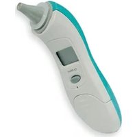
25580 - Thermometer GIMA - Free user manual and instructions
Find the device manual for free 25580 GIMA in PDF.


| Product Type | Digital Thermometer |
| Brand | GIMA |
| Model | 25580 |
| Measurement Range | 32.0°C - 42.0°C |
| Accuracy | ±0.1°C |
| Display | LCD |
| Memory | Last reading |
| Auto Shut-off | Yes, after approx. 10 minutes |
| Battery | 1 × 1.5V LR41 (included) |
| Dimensions | 12.5 × 2.5 × 1.5 cm |
| Weight | Approx. 25 g (with battery) |
| Material | Plastic body, stainless steel tip |
| Water Resistance | Not waterproof; wipe clean only |
| Cleaning | Wipe with isopropyl alcohol before and after each use |
| Measurement Sites | Oral, axillary, rectal |
| Measurement Time | ~60 seconds (oral/axillary), ~10 seconds (rectal) |
| Certifications | CE, ISO 13485 |
| Warranty | 1 year |
| Included Accessories | Battery, storage case, user manual |
Frequently Asked Questions - 25580 GIMA
User questions about 25580 GIMA
0 question about this device. Answer the ones you know or ask your own.
Ask a new question about this device
Download the instructions for your Thermometer in PDF format for free! Find your manual 25580 - GIMA and take your electronic device back in hand. On this page are published all the documents necessary for the use of your device. 25580 by GIMA.
USER MANUAL 25580 GIMA
TERMOMETRO AURICOLARE IR EAR THERMOMETER THERMOMETRE AURICOLAIRE OHRENTHERMOMETER TERMÓMETRO AURICULAR TERMÔMETRO AURICULAR ÕEPMOMETPO AYTIOY
Model: TH889

25580

Gima S.p.A.
Via Marconi, 1 - 20060 Gessate (MI) Italy
gima@gimaitaly.com - export@gimaitaly.com
www.gimaitaly.com
Made in China
IP22


0476


Intended use
The ear thermometer is electronic thermometer using an infrared detector (thermopile detector) to detect body temperature from ear canal in people of all ages.
Intended operator: Have eight years of education, no maximum.
Thank you for purchasing the thermometer. This thermometer is designed with an advanced infrared and ambient temperature compensation technology for instantaneous self-diagnosis and accurate temperature measurements. Do not use this device for Live & Dead decision or Safety related applications.
Please consult with doctor if you have health concerns.

Operating Instructions
NOTE: The device must stay in stable ambient (room) temperature for 15 minutes before operating.
-
Gently squeeze the opposite ends of the thermometer to pull off the probe cap. Do not use force to remove the cap.
-
Always use a new and undamaged probe cover. Make sure the ear canal is clean.

Warning: Choking from swallowing small parts and batteries by children or pets is possible, please keep small parts and batteries at places where children and pets can't reach.
- Install Probe Cover
1) Place a new probe cover on the connection ring. (See Figure 1)
NOTE: Make sure to place the "Adhesive Side" of probe cover "Upward."
2) Align the probe with the center of probe cover. Insert the probe into the probe cover on the connection ring. (See Figure 2)
3) Push the connection ring until the "Click" sound. This means the probe cover has been installed successfully.
NOTE: If the probe cover did not connect firmly, the “▷” icon will flash on the LCD screen. Please check the setting of the probe cover again.

Figure 1 Figure 2

Proper installation of the probe cover and using the specific probe cover ensure accurate measurements.
-
Press "ON/MEM" button to power on. The thermometer is ready for use after the ear icon stop flashing and two short beep sound.
-
Gently pull the ear back to straighten the ear canal and snugly position the probe into the ear canal, aiming towards the membrane of the eardrum to obtain an accurate reading. (Fig.4-1)
-
Measuring the ear temperature: Use the index finger to trigger. Press the "Scan" button until you hear a long beep. (Fig.4-2). After each ear measurement, wait "7" icon stop flashing to be ready for next measurement.
-
Power off: This device will automatically shut down after 1 minute pending to extend battery life.

Figure 4-1

Figure 4-2
NOTE
a. Before the measurement, please stay in a stable environment for 5mins and avoid the exercise, bath for 30mins.
b. It is recommended that you measure 3 times with the same ear. If the 3 measurements are different, select the highest temperature.
c. To avoid the risk of cross contamination, please clean the probe according to "Cleaning and Storage" section after each use.
d. The "Clinical Bias" is -0.2 \~ -0.4°C.
e. The "Limits of Agreement" is 0.58.
f. The "Repeatability" is 0.17° C .
Fever Indication:
If the thermometer detects a body temperature ≥37.5°C (or 99.5°F ), three short beep sound will follow one long beep sound to warn the user for potential fever.
Switching between Fahrenheit (°F) and Celsius (°C):
In "Power Off" mode, press and hold the "SCAN" button, then press the "ON/MEM" button for 3 seconds, icon "°C" will be switched to icon "°F". You can also use the same process to change the LCD display from °F to °C.
Memory Function:
When in power on, press the "ON/MEM" button to see the temperature stored. The thermometer provides 9 sets memory for the body temperature.
Cleaning and Storage:
The probe is the most delicate part of the thermometer. Use with care when cleaning the lens to avoid damage.

** The probe cover is disposable: throw it away and replace it after each use to ensure an accurate reading and avoid cross contamination.
Storage temperature Range: It should be stored at room temperature between -20\~+50°C, RH ≤85% Keep the unit dry and away from any liquids and direct sunlight. The Probe should not submerge into any liquids.
** If device is accidentally used without probe cover, clean the probe as follows:
a. Please use the cotton swab with Alcohol (70% concentration) to clean the lens( on the inside of the probe).
b. Allow the probe to fully dry for at least 1 minute.
NOTE: Please check the device if damaged once it falls. If you can't make sure of it, please send the complete device to the nearest retailer for recalibration.
Holding the thermometer too long may cause a higher ambient temperature reading of the probe.
This could make the body temperature measurement lower than usual.


Changing the Battery:
This device is supplied with one lithium cell (CR2032 x 1).
-
Open the battery cover: Insert a pointed object into the battery cover pick hole. At the same time, use thumb to remove battery cover. (See Figure 1)
-
Flip the battery out with a small screw driver (See Figure 2)
-
Insert the new battery under the metal hook on the left side and press the right side of the battery down until you hear a "click". (See Figure 3)
-
Replace the battery cover.
The positive (+) side Up and the negative (-) side pointed Down.
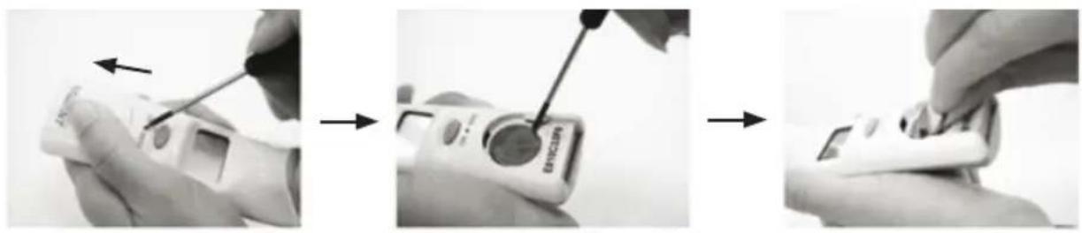
Figure 1 Figure 2 Figure 3
Specifications:
- Operating temperature range: 10\~40°C (50\~104°F), 15%\~85% RH
- Storage temperature Range: It should be stored at room temperature between -20\~+50°C, RH ≤85% Transportation temperature shall be less than 70°C, RH ≤95%
- Atmospheric pressure: 800\~1013 hPa
- Comply with ASTM E1965-98, EN ISO 80601-2-56, IEC/EN60601-1-2(EMC), IEC/EN60601-1(Safety) standards, ISO10993, RoHS.
- Accuracy: ±0.2°C (0.4°F) within 35\~42°C (95\~107.6°F), ±0.3°C (0.5°F) for other range.
- This thermometer is an adjusted mode thermometer that converts the ear temperature to display its "oral equivalent" (according to the result of the clinical evaluation to get the offset value)
- Enclosure Rating: IP22
- Dimensions: 149.1 x 42.5 x 54.9 mm
- Weight: 79.7 grams including battery
- Battery life: around 3,000 continuous readings.
- Product life: 4 years

The device should not submerge into any liquids and expose it to direct moisture.
There is no gender and age limitation for using infrared thermometer.
This is not an AP or APG product.
NOTE: The thermometer is calibrated at the time of manufacture. If at any time you question the accuracy of temperature measurements, please contact the dealers or nearest service address.
Throubleshooting
| Error message Problem Solution | ||
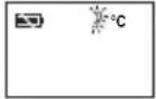 | Device stabilization in process. | Wait until stops flashing. |
 | Battery is low and no more measurements are possible. | Replace the battery. |
 | Measurement before device stabilization. | Wait until stops flashing. |
 | The ambient temperature is not within the range between 10°C and 40°C (50°F ÷ 104°F). | Allow the thermometer to rest in a room at least 15 minutes at room temp. (10°C ÷ 40°C, 50°F ÷ 104°F). |
 | Error 5 ÷ 9, the system is not functioning properly. | Unload the battery, wait for 1 minute and repower it. If the message reappears, contact the retailer for service. |
 | Temperature taken is higher than 42,2°C (108°F). | Check the integrity of the probe cover and take a new temperature measurement. |
 | Temperature taken is lower than 34°C (93,2°F). | Make sure the probe cover and the lens are clean and take a new temperature measurement. |
 | Device can not be powered on to the ready stage. | Change with a new battery. |
| Symbols | |||||
| CE | Medical Device complies with Directive 93/42/EEC | Product code WEEE disposal | |||
| Caution: read instructions (warnings) carefully | Lot number Keep away from sunlight | ||||
| Follow instructions for use Manufacture | weep in a cool, dry place | ||||
| Type BF applied part | Date of manufacture | IP22 | Covering Protection rate | ||
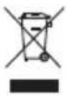
Disposal: The product must not be disposed of along with other domestic waste. The users must dispose of this equipment by bringing it to a specific recycling point for electric and electronic equipment.
GIMA WARRANTY TERMS
The Gima 12-month standard B2B warranty applies.
| Guidance and manufacturer's declaration – electromagnetic emissions | ||
| The device is intended for use in the electromagnetic environment specified below. The customer or the user of the device should assure that it is used in such an environment. | ||
| Emissions test Compliance Electromagnetic environment – guidance | ||
| RF emissionsCISPR 11 | Group 1 The device uses RF energy only for its internal function.Therefore, its RF emissions are very low and are not likely to cause any interference in nearby electronic equipment. | |
| RF emissionsCISPR 11 | Class B The device is suitable for use in all establishments, including domestic establishments and those directly connected to the public low-voltage power supply network that supplies buildings used for domestic purposes | |
| Guidance and manufacturer's declaration - electromagnetic immunity | |||
| The device is intended for use in the electromagnetic environment specified below. The customer or the user of the device should assure that it is used in such an environment. | |||
| Immunity test IEC 60601 test level | Compliance Electromagnetic environment - guidance | ||
| Radiated RF IEC 61000-4-3 | 10 V/m80 MHz to 2.7 GHz80% AM at 1KHz | 10 V/m80 MHz to 2.7 GHz80% AM at 1KHz | Recommended separation distance d = 1.2 d = 1.2 80 MHz to 800 MHz d = 2.3 800 MHz to 2.7 GHzWhere P is the maximum output power rating of the transmitter in watts (W) according to the transmitter manufacturer and d is the recommended separation distance in meters (m).Field strengths from fixed RF transmitters, as determined by an electromagnetic site survey, a should be less than the compliance level in each frequency range.Interference may occur in the vicinity of equipment marked  with the following symbol: with the following symbol: |
| NOTA 1 At 80 MHz and 800 MHz, the higher frequency range applies.NOTA 2 These guidelines may not apply in all situations. Electromagnetic propagation is affected by absorption and reflection from structures, objects and people. | |||
| a Field strengths from fixed transmitters, such as base stations for radio (cellular/cordless) telephones and land mobile radios, amateur radio, AM and FM radio broadcast and TV broadcast cannot be predicted theoretically with accuracy. To assess the electromagnetic environment due to fixed RF transmitters, an electromagnetic site survey should be considered. If the measured field strength in the location in which the device is used exceeds the applicable RF compliance level above, the device should be observed to verify normal operation. If abnormal performance is observed, additional measures may be necessary, such as reorienting or relocating the device.Guidance and manufacturer's declaration – electromagnetic immunity | |||
| The device is intended for use in the electromagnetic environment specified below. The customer or the user of the device should assure that it is used in such an environment. | |||
| Immunity test IEC 60601 test level | Compliance level | Electromagnetic environment - guidance | |
| Electrostatic discharge (ESD)IEC 61000-4-2 | contact ±8 Kv air ±2, ±4, ±8, ±15 kv | contact ±8 Kv air ±2, ±4, ±8, ±15 Kv | Floors should be wood, concrete or ceramic tile.If floors are covered with synthetic material, the relative humidity should be at least 30 %. |
| Power frequency (50/60 Hz) magnetic field IEC 61000-4-8 | 30 A/m50 Hz or 60Hz | 30 A/m50 Hz or 60Hz | Power frequency magnetic fields should be at levels characteristic of a typical location in a typical commercial or hospital environment. |
| Recommended separation distances between portable and mobile RF communications equipment and the ME EQUIPMENT or ME SYSTEM | |||||||
| The device is intended for use in an electromagnetic environment in which radiated RF disturbances are controlled. The customer or the user of the device can help prevent electromagnetic interference by maintaining a minimum distance between portable and mobile RF communications equipment (transmitters) and the device as recommended below, according to the maximum output power of the communications equipment. | |||||||
| Rated maximum output power of transmitter W | Separation distance according to frequency of transmitter m | ||||||
| 150KHz to 80MHz d = 1.2 | 80MHz to 800MHz d = 1.2 | 800MHz to 2.7GHz d = 2.3 | |||||
| 0.01 N/A 0.12 | 0.23 | ||||||
| 0.1 N/A 0.38 | 0.73 | ||||||
| 1 N/A 1.2 | 2.3 | ||||||
| 10 N/A 3.8 | 7.3 | ||||||
| 100 N/A 12 | 23 | ||||||
| For transmitters rated at a maximum output power not listed above, the recommended separation distance d in meters (m) can be estimated using the equation applicable to the frequency of the transmitter, where P is the maximum output power rating of the transmitter in watts (W) according to the transmitter manufacturer.NOTE 1 At 80 MHz and 800 MHz, the separation distance for the higher frequency range applies. NOTE 2 These guidelines may not apply in all situations. Electromagnetic propagation is affected by absorption and reflection from structures, objects and people. | |||||||
| Manufacturer's declaration-electromagnetic immunity | |||||||
| Test specifications for ENCLOSURE PORT IMMUNITY to RF wireless communications equipmentThe device is intended for use in the electromagnetic environment (for home healthcare) specified below. The customer or the user of the device should assure that it is used in such an environment | |||||||
| Test frequency (MHz) | Banda) (MHz) | Servicea) | Modulationb) | Maximum power (W) | Distance (m) | IMMUNITY TEST LEVEL (V/m) | Compliance LEVEL (V/m)(for home healthcare) |
| 385 380 - 390 TETRA 400 Pulse | modulation b)18 Hz | 1,8 0,3 27 27 | |||||
| 450 430 - 470 GMRS 460, | FRS 460 | FM c) □±5 kHz deviation 1 kHz sine | 2 0,3 28 28 | ||||
| 710 704 - 787 LTE Band | 13, 17 | Pulse modulation b)217 Hz | 0,2 0,3 9 9 | ||||
| 745 | |||||||
| 780 | |||||||
| 810 800 - 960 GSM 800/900, | TETRA 800,iDEN 820,CDMA 850,LTE Band 5 | Pulse modulation b)18 Hz | 2 0,3 28 28 | ||||
| 870 | |||||||
| 930 | |||||||
| 1 720 1700 - | 1990 | GSM 1800;CDMA 1900;GSM 1900;DECT;LTE Band 1, 3,4, 25; UMTS | Pulse modulation b)217 Hz | 2 0,3 28 28 | |||
| 1 845 | |||||||
| 1 970 | |||||||
| 2 450 2400 - | 2570 | Bluetooth,WLAN,802.11 b/g/n,RFID 2450,LTE Band 7 | Pulse modulation b)217 Hz | 2 0,3 28 28 | |||
| 5 240 5100 - | 5800 | WLAN802.11 a/n | Pulse modulation b)217 Hz | 0,2 0,3 9 9 | |||
| 5 500 | |||||||
| 5 785 | |||||||
| NOTE If necessary to achieve the IMMUNITY TEST LEVEL, the distance between the transmitting antenna and the ME EQUIPMENT or ME SYSTEM may be reduced to 1 m. The 1 m test distance is permitted by IEC 61000-4-3. | |||||||
| a) For some services, only the uplink frequencies are included.b) The carrier shall be modulated using a 50 % duty cycle square wave signal.c) As an alternative to FM modulation, 50 % pulse modulation at 18 Hz may be used because while it does not represent actual modulation, it would be worst case. | |||||||


Brand : GIMA
Model : 25580
Category : Thermometer