
DIMAGE A2 - Digital Camera KONICA MINOLTA - Free user manual and instructions
Find the device manual for free DIMAGE A2 KONICA MINOLTA in PDF.

| Product type | Digital camera with 7x optical zoom |
| Brand and model | Konica Minolta DiMAGE A2 |
| Sensor | CCD 2/3 type, 8.3 million pixels (effective 8.0 million) |
| ISO sensitivity | Auto, 64, 100, 200, 400, 800 |
| Lens | 7.2 - 50.8 mm (35mm equivalent: 28 - 200 mm), aperture f/2.8 - f/3.5 |
| Filter | Diameter 49 mm |
| Macro mode | From 0.25 m (tele) to 0.3 m (wide-angle) |
| Viewfinder | Electronic viewfinder (EVF) 0.44 inch color, tilts up to 90° |
| LCD screen | TFT 1.8 inch screen, tilts from -20° to +90° |
| Stabilizer | Anti-shake (sensor shift) |
| Built-in flash | Pop-up flash, range 0.5 - 3.8 m (W) / 0.5 - 3.0 m (T) |
| Storage media | CompactFlash Type I/II, IBM Microdrive |
| Image formats | JPEG, TIFF, RAW, RAW+JPEG, Motion JPEG (AVI), WAV |
| Power source | Lithium-ion battery NP-400 (7.4 V, 1500 mAh) or AC adapter AC-1L/AC-11 |
| Battery life | Approximately 280 photos (CIPA standard) |
| Dimensions (W x H x D) | 117 x 85 x 113.5 mm |
| Weight | Approximately 565 g (without battery or memory card) |
| Operating temperature | 0 °C to 40 °C |
| Cleaning | Soft, dry cloth; blow off dust before wiping the lens |
| Supplied accessories | NP-400 battery, BC-400 charger, neck strap, lens hood, lens cap, AV and USB cables, DiMAGE Viewer CD-ROM |
Frequently Asked Questions - DIMAGE A2 KONICA MINOLTA
User questions about DIMAGE A2 KONICA MINOLTA
0 question about this device. Answer the ones you know or ask your own.
Ask a new question about this device
Download the instructions for your Digital Camera in PDF format for free! Find your manual DIMAGE A2 - KONICA MINOLTA and take your electronic device back in hand. On this page are published all the documents necessary for the use of your device. DIMAGE A2 by KONICA MINOLTA.
USER MANUAL DIMAGE A2 KONICA MINOLTA
natural_image
Black KONICA MINOLTA digital camera with visible lens and aperture specifications (no text beyond branding)
INSTRUCTION MANUAL
Before you Begin
Thank you for purchasing this Konica Minolta digital camera. Please take the time to read through this instruction manual so you can enjoy all the features of your new camera.
Check the packing list before using this product. If any items are missing, immediately contact your camera dealer.
DiMAGE digital camera
Lithium-ion battery NP-400
Lithium-ion battery charger BC-400
Neck strap NS-DG4000
Lens shade DLS-2
Lens cap LF-1349
Accessory shoe cap SC-10
AV cable AVC-400
USB cable USB-500
Ferrite Core FRC-100
DiMAGE Viewer CD-ROM
DiMAGE Instruction Manuals CD-ROM
Quick Reference Guide
Konica Minolta International Warranty Certificate
This product is designed to work with accessories manufactured and distributed by Konica Minolta. Using accessories or equipment not endorsed by Konica Minolta may result in unsatisfactory performance or damage to the product and its accessories.
Konica Minolta is a trademark of Konica Minolta Holdings, Inc. DiMAGE is a trademark of Konica Minolta Camera, Inc. Apple, Macintosh, and Mac OS are registered trademarks of Apple Computer Inc. Microsoft and Windows are registered trademarks of the Microsoft Corporation. The official name of Windows is Microsoft Windows Operating System. Pentium is a registered trademark of the Intel Corporation. Microdrive is a trademark of the International Business Machines Corporation. QuickTime is a trademark used under license. Adobe is a registered trademark of Adobe Systems Incorporated. All other brand and product names are trademarks or registered trademarks of their respective owners.
For Proper and Safe Use
NP-400 Lithium-ion Batteries
This camera operates on a powerful lithium-ion battery. Misuse or abuse of the lithium-ion battery can cause damage or injury through fire, electric shock, or chemical leakage. Read and understand all warnings before using the battery.
Danger
- Do not short, disassemble, damage, or modify the battery.
- Do not expose the battery to fire or high temperatures over 60^ (140°F).
- Do not expose the battery to water, or moisture. Water can corrode or damage the internal battery safety devices and cause the battery to overheat, ignite, rupture, or leak.
- Do not drop or subject the battery to strong impacts. Impacts can damage the internal battery safety devices and cause the battery to overheat, ignite, rupture, or leak.
- Do not store the battery near or in metallic products.
- Do not use the battery with any other products.
- Only use the specified charger. An inappropriate charger may cause damage or injury through fire or electric shock.
- Do not use a leaking battery. If fluid from the battery enters your eye, immediately rinse the eye with plenty of fresh water and contact a doctor. If fluid from the battery makes contact with your skin or clothing, wash the area thoroughly with water.
- Only use or charge the battery in an environment with ambient temperatures between 0° and 40°C (32° and 104°F). Only store the battery in an environment with ambient temperatures between -20° and 30°C (-4° and 86°F) and a humidity of 45% to 85% RH.
Warning
- Tape over the lithium-ion battery contacts to avoid short-circuiting during disposal; always follow local regulations for battery disposal.
- If charging is not completed after the specified period elapses, unplug the charger and discontinue charging immediately.
General Product Warnings and Cautions
Read and understand the following warnings and cautions for safe use of the digital camera and its accessories.
Warning
- Only use the battery specified in this manual.
- Only use the specified charger or AC adapter within the voltage range indicated on the unit. An inappropriate adapter or current may cause damage or injury through fire or electric shock.
- Only use the charger power cord in the sales region for which it was designed. An inappropriate current may cause damage or injury through fire or electric shock.
- Do not disassemble the camera or charger. Electric shock may cause injury if a high voltage circuit inside the product is touched.
- Immediately remove the battery or unplug the AC adapter and discontinue use if the camera is dropped or subjected to an impact in which the interior, especially the flash unit, is exposed. The flash has a high voltage circuit which may cause an electric shock resulting in injury. The continued use of a damaged product or part may cause injuries or fire.
- Keep the battery, memory card, or small parts that could be swallowed away from infants. Contact a doctor immediately if an object is swallowed.
- Store this product out of reach of children. Be careful when around children not to harm them with the product or parts.
- Do not fire the flash directly into the eyes. It may damage eyesight.
- Do not fire the flash at vehicle operators. It may cause a distraction or temporary blindness which may lead to an accident.
- Do not use the monitor while operating a vehicle or walking. It may result in injury or an accident.
- Do not use these products in a humid environment, or operate them with wet hands. If liquid enters these products, immediately remove the battery or unplug the product, and discontinue use. The continued use of a product exposed to liquids may cause damage or injury through fire or electric shock.
- Do not use these products near inflammable gases or liquids such as gasoline, benzine, or paint thinner. Do not use inflammable products such as alcohol, benzine, or paint thinner to clean these products. The use of inflammable cleaners and solvents may cause an explosion or fire.
- When unplugging the AC adapter or charger, do not pull on the power cord. Hold the plug when removing it from an outlet.
- Do not damage, twist, modify, heat, or place heavy objects on the AC adapter or charger cord. A damaged cord may cause damage or injury through fire or electric shock.
- If these products emit a strange odor, heat, or smoke, discontinue use. Immediately remove the battery taking care not to burn yourself as the battery may become hot with use. The continued use of a damaged product or part may cause injuries or fire.
• Take the product to a Konica Minolta service facility when repairs are required.

Caution
- Do not use or store these products in a hot or humid environment such as the glove compartment or trunk of a car. It may damage the camera, charger, and battery which may result in burns or injuries caused by heat, fire, explosion, or leaking battery fluid.
- If the battery is leaking, discontinue use of the product.
- The camera, charger, and battery temperature rises with extended periods of use. Care should be taken to avoid burns.
- Burns may result if the memory card or battery is removed immediately after extended periods of use. Turn the camera off and wait for it to cool.
- Do not fire the flash while it is in contact with people or objects. The flash unit discharges a large amount of energy which may cause burns.
- Do not apply pressure to the LCD monitor. A damaged monitor may cause injury, and the liquid from the monitor may cause inflammation. If liquid from the monitor makes contact with skin, wash the area with fresh water. If liquid from the monitor comes in contact with the eyes, immediately rinse the eyes with plenty of water and contact a doctor.
- When using the AC adapter and charger, insert the plug securely into the electrical outlet.
- The rim of the lens hood can cause injury. Take care not to accidentally strike anyone with the camera when the lens hood is attached.
- Do not use electronic transformers or travel adapters with the charger. The use of these devices may cause a fire or damage the product.
- Do not use if the AC adapter or charger cord is damaged.
- Do not cover the AC adapter or charger. A fire may result.
- Do not obstruct access to the AC adapter or charger; this can hinder the unplugging of the units in emergencies.
- Unplug the AC adapter or charger when cleaning or not in use.
Table of Contents
Before you begin....3
For proper and safe use ....4
Names of parts ....14
Camera body....14
Data panel 17
Monitor display - recording mode....18
Monitor display - Quick View & playback mode....19
Getting up and running....20
Attaching the camera strap....20
Removing the lens cap....20
Attaching the lens hood 21
Charging the battery....22
Installing and changing the battery....23
Battery condition indicator....24
Auto power save 24
External power supplies (sold separately) 25
Inserting and changing a memory card 26
Turning on the camera 28
Handling the camera....28
Adjusting the viewfinder and monitor 29
Diopter adjustment....29
Setting the date and time....30
Basic recording 32
Setting the camera to record images automatically 32
EVF and LCD monitor display....32
Basic recording operation....33
Focus lock....34
Automatic monitor amplification ....34
Focus signals 35
Special focusing situations 35
Using the built-in flash 36
Flash range - automatic operation....36
Anti-shake system....37
Movie recording....38
Display mode switch....39
Basic playback 40
Single-frame playback and histogram display....40
Viewing images and histogram....41
Rotating images 41
Deleting single images 41
Changing the Quick View & playback display 42
Enlarged playback....43
Viewing movies....44
Advanced recording....45
Display-information button....45
Focus-mode switch....46
Digital zoom....47
Flex Focus Point....48
Macro mode 49
Exposure lock....50
Exposure-mode dial ....50
Program - P 51
Program shift - Pa/Ps 51
Auto recording....52
Aperture priority - A....54
Shutter priority - S....55
Shutter-speed range and camera sensitivity (ISO) 55
Manual exposure - M 56
Bulb exposures 57
Attaching a remote cord (sold separately)....57
Digital Subject Programs 58
Exposure and flash compensation....59
Using the function dial 60
Drive modes 61
Bracketing....62
Continuous advance....64
Interval 66
Self-timer 68
Metering modes 69
White balance....70
Custom white balance calibration....71
Memory - storing camera settings....72
Memory recall....73
Camera sensitivity - ISO 74
Flash range and camera sensitivity....75
Attaching an accessory flash unit....75
Using the flash sync terminal....76
Depth-of-field preview....77
Digital Effects Control 78
Color-saturation compensation....78
Contrast compensation....79
Filter....79
Recording menu....80
Navigating the recording-mode menu 80
Image size and image quality....82
About RAW image quality 84
Notes on image size and resolution....85
Flash modes....86
Wireless/Remote flash....88
Wireless/Remote camera and flash ranges....90
Notes on wireless/remote flash....91
Flash control....92
AEL button 94
Recording-mode reset 95
Interval setup....96
Bracketing setup 96
Sharpness 97
Data imprinting 98
Electronic keyboard....99
Instant playback....100
Voice memo....101
Color mode....102
About Adobe RGB....103
Noise reduction 103
Monitor amplification....104
Magnification button 105
Flex Digital Magnifier....105
DSP (Digital Subject Program) setup....106
Tracking AF....106
AE lock 106
Spot AE area 107
Direct Manual Focus 107
EVF mode....108
A short guide to photography....109
About exposure and flash compensation....110
What is an Ev? 111
Light sources and color....111
Movie menu 112
Navigating the movie menu 112
Image size and frame rate....113
Movie mode....113
Movie reset....114
Notes on movie recording....114
Advanced playback....115
Playing back voice memos 115
Navigating the playback menu....116
Frame-selection screen....118
Delete 119
Format 120
View folder....120
Lock 121
Index playback format....121
Copy 122
Slide Show 124
About DPOF 126
DPOF setup....126
Date imprint....127
Index print 127
Cancel print 127
Viewing images on a television 128
Setup menu 129
Opening the setup menu....129
Navigating the setup menu....130
LCD brightness....132
Shortcut help....132
Transfer mode 135
EVF auto switch 135
Video output....135
Language....135
Custom setup....136
File number memory 136
Folder name 137
Select folder 137
New folder....138
Date and time setup....138
Reset default 139
Audio signals....141
Focus signals 141
Shutter FX....142
Volume 142
Auto power save 142
Anti-shake 143
Full-time AF 143
Grip sensor....143
Control dial setup....144
Control dial setup - Manual exposure....145
Delete confirmation 145
Lens accessory 145
Data-transfer mode....146
System requirements 146
Connecting the camera to a computer....147
Connecting to Windows 98 / 98 second edition ....148
Automatic installation 148
Manual installation....149
QuickTime system requirements....151
Auto power save (Data-transfer mode)....151
Memory card folder organization 152
Disconnecting the camera from the computer 154
Windows 98 / 98 second edition .....154
Windows Me, 2000 Professional, and XP 154
Macintosh 155
Changing the memory card (data-transfer mode) 156
Removing the driver software - Windows....157
PictBridge....158
Notes on printing errors 159
Navigating the PictBridge menu 160
Troubleshooting....164
When using filters....166
About the lithium-ion battery charger cord....167
Attaching the ferrite core FRC-100....167
Care and storage 168
Camera care....168
Cleaning 168
Storage....168
Operating temperatures and conditions 169
Memory card care and handling 169
Batteries 170
LCD monitor care....170
Copyright....170
Before important events or journeys....171
Questions and service....171
Notes 172
Index 174
Technical specifications....176
Battery Pack BP-400 178
Filter examples 179
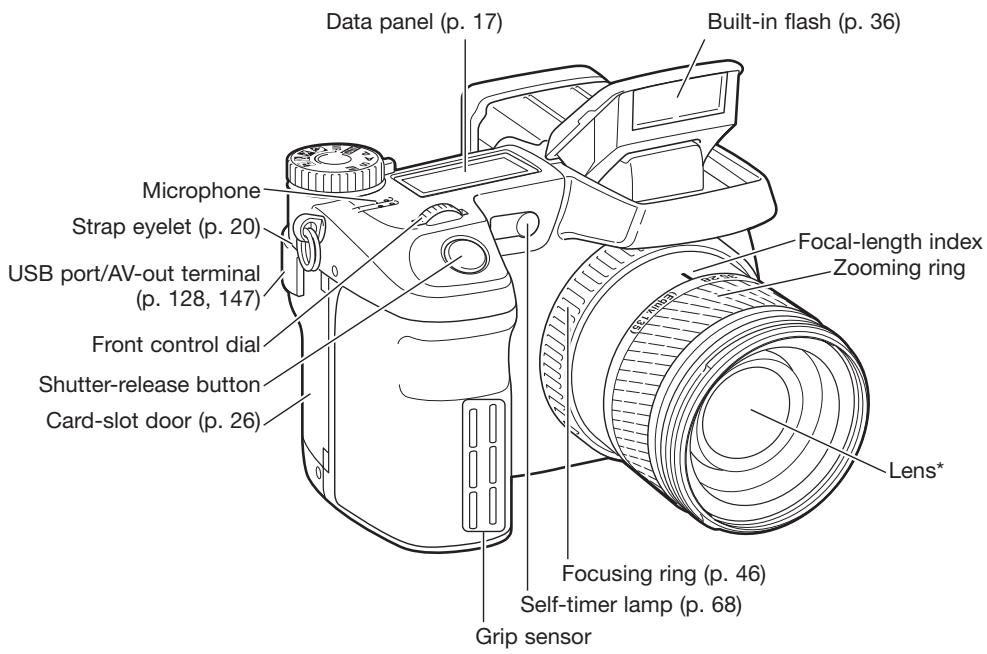
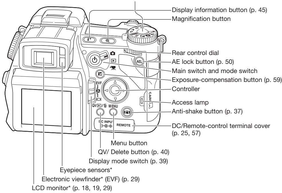
Names of Parts
Camera Body
* This camera is a sophisticated optical instrument. Care should be taken to keep these surfaces clean. Please read the care and storage instructions in the back of this manual (p. 168).
Camera Notes
The focal-length scale on the zooming ring is given in 35mm focal-length equivalents. The DiMAGE Viewer software supplied with the camera can display the actual focal length used to capture the recorded image as well as the equivalent focal length in 35mm photography.
Manual exposure (p. 56) M
Shutter priority (p. 55) S
Aperture priority (p. 54) A
Program exposure (p. 51) P
Auto recording (p. 52) AUTO

MR Memory recall (p. 73)
Portrait subject program (p. 58)
Sports action subject program (p. 58)
Sunset subject program (p. 58)
Night portrait subject program (p. 58)
Exposure-mode dial
Function button
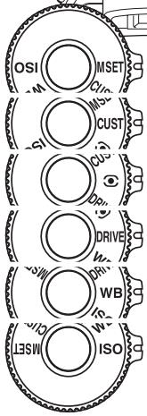
Metering modes (p. 69) Custom function (p. 136) CUST Memory set (p. 72) MSET
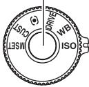
DRIVE Drive modes (p. 61)
WB White balance (p. 70)
ISO Camera sensitivity (p. 74)

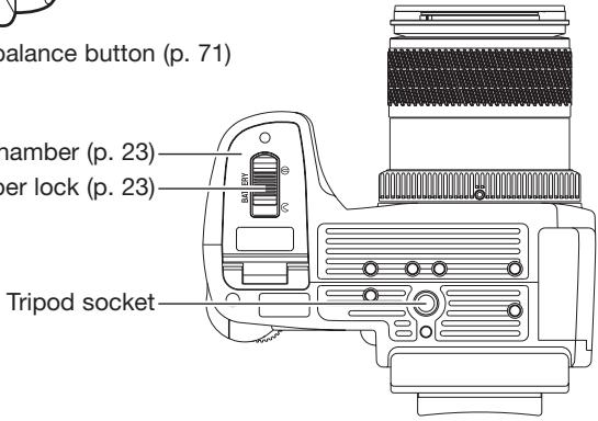
Battery-chamber (p. 23)
Battery-chamber lock (p. 23)
Data Panel
Located on the top of the camera body, the data panel shows the status of the camera. All icons have been shown for clarity. The single-frame advance and continuous advance indicators are displayed in the same area of the data panel.
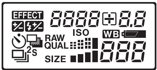
EFFECT

Digital-effects indicator (p. 78)
Exposure-compensation indicator (p. 59)
Flash-compensation indicator (p. 59)
Single-frame advance (p. 33)
Continuous advance (p. 64)
Bracketing (p. 62)
Self-timer (p. 68)
RAW QUAL
Image-quality display (p. 82)
SIZE
Image-size display (p. 82)

Camera-sensitivity indicator (p. 74)
White-balance indicator (p. 70)
#
Battery-condition indicator (p. 24)
8888+8.8
Shutter-speed and aperture display & exposure/flash compensation display
888
The frame counter cannot exceed 999. When the number of recordable images exceeds this, 999 will be displayed. The frame counter will continue to count down when the number of recordable images falls below one thousand.
natural_image
Line drawing of a camera with a digital display and control panel (no text or symbols)Monitor Display - Recording Mode
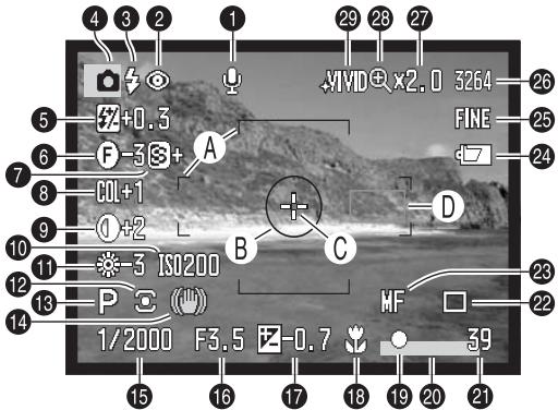
- Microphone indicator 20.
- Flash-mode indicator (p. 61) 21.
- Flash signal (p. 36) 22.
- Mode indicator 23.
- Flash-compensation display (p. 59) 24.
- Filter display (p. 78) 25.
- Sharpness display (p. 97) 26.
- Color-saturation-compensation display (p. 78) 27.
- Contrast-compensation display (p. 78) 29.
Camera-sensitivity (ISO) display (p. 74)
White-balance indicator (p. 70)
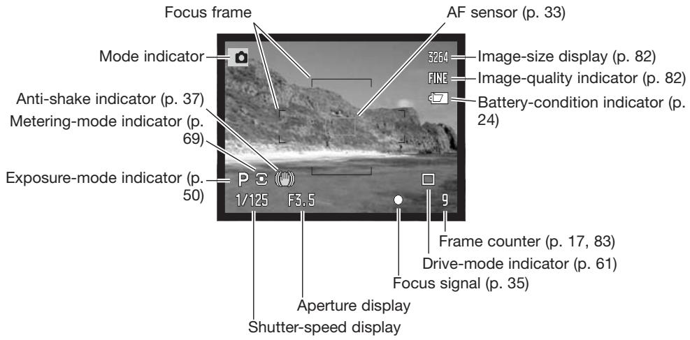
Metering-mode indicator (p. 69)
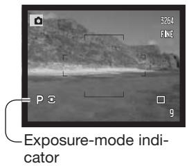
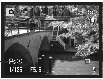
Exposure-mode indicator (p. 50)
Anti-shake indicator (p. 37)
Shutter-speed display
Aperture display
Exposure-compensation display (p. 59)
Macro-mode indicator (p. 49)
Focus signal (p. 35)
Data-imprinting indicator (p. 98)
Frame counter (p. 83)
Drive-mode indicator (p. 61)
Manual-focus indicator (p. 46)
Battery-condition indicator (p. 24)
Image-quality indicator (p. 82)
Image-size display (p. 82)
Magnification display (p. 47, 105)
Flex Digital Magnifier indicator (p. 105)
Color-mode indicator (p. 102)
A. Focus frame
B. Spot metering area (p. 69)
C. Flex Focus Point (p. 48)
D. AF sensors
Monitor Display - Quick View & Playback Mode
![12 x2.0 3264 FINE 9 8 13:24 2004.02.27 [10n 3 [0024/0093]] 4 5 6 11 7 1 3264 FINE 1/2000 F3.5 -0.7 AWB ISO200 KM003 100-0135 1. 2. 3. 4. 5. 6 13. 14. 15. 16. 17. 18. 19. 3 Histogram 2004.02.27 [10n 3 100-0135](/content/2025/01/139770/images/29b0552eea6c931f09a18f2b3256a0966fa178829322ad0ea4eacbf64517825e.jpg)
Mode indicator
Time of capture
Date of capture
Voice-memo indicator (p. 115)
Lock indicator (p. 121)
Print indicator (p. 126)
Frame number / total number of images
Scroll arrows (p. 43)
Battery-condition indicator (p. 24)
Image-quality indicator (p. 82)
Image-size display (p. 82)
Magnification display (p. 43)
Folder number - image file number
Folder name (p. 137)
Sensitivity setting (p. 74)
White-balance setting (p. 70)
Degree of exposure compensation (p. 59)
Aperture value
Shutter-speed
The dark area of the histogram shows the luminance distribution of the recorded image from black (left) to white (right). Each one of the 256 vertical lines indicates the relative proportion of that light value in the image. The histogram can be used to evaluate exposure and contrast, but displays no color information.
Getting Up and Running
This section covers the preparation of the camera. This includes the changing of batteries and memory card as well as the use of external power supplies.
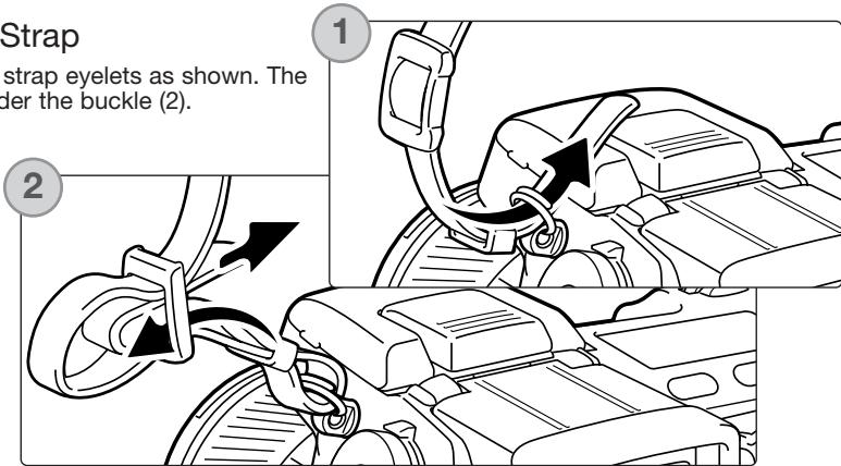
Attaching the Camera Strap
Attach the camera strap to the strap eyelets as shown. The tip of the strap should pass under the buckle (2).
Always keep the camera strap around your neck in case you drop the camera.
natural_image
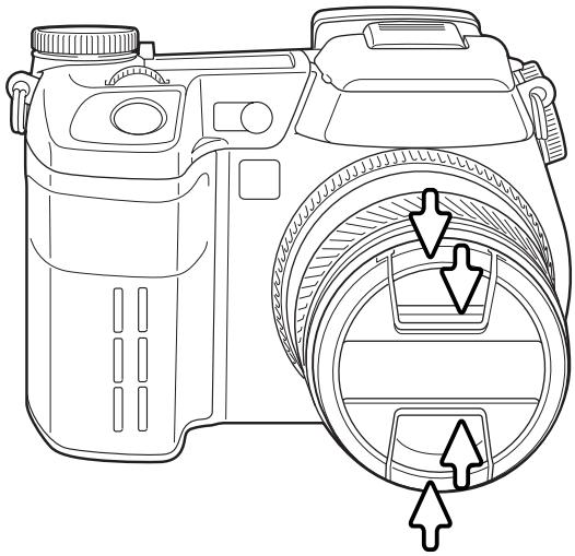
Line drawing of a DSLR camera with circular adjustment knobs and directional arrows indicating alignment (no text or symbols)Removing the Lens Cap
Using your thumb and index finger, pinch the inside or outside tabs of the lens cap to remove. When the camera is not in use, always replace the lens cap.
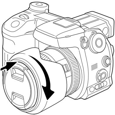
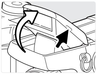
Attaching the Lens Hood
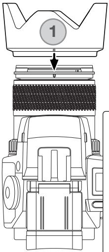
The lens hood is used to control stray light from entering the lens and causing flare. When using the camera under bright light, the use of the lens hood is recommended. The lens hood should not be used with the built-in flash as it can cause a shadow.
To mount the lens hood, align the rectangular dimple on the rim of the hood with the focal-length index on the top of the lens barrel (1).
natural_image
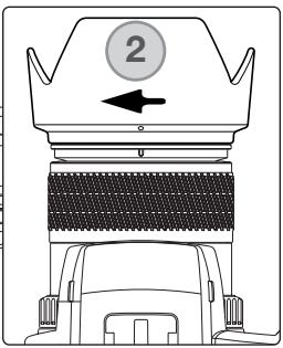
Diagram of a vehicle's top-down view showing a roof, grille, and side-mounted sensors (no text or symbols)Slide the hood onto the end of the lens and turn it 90° clockwise until it clicks and the circular dimple is aligned with the focal-length index (2). When mounted correctly, the large petals of the lens hood should be to the top and bottom. Never force the lens hood. If it does not fit, check its orientation. To detach the lens hood, turn it 90° counterclockwise and remove.
The lens hood can be reverse mounted when the camera is not is use.
With one of the large petals to the top, slide the hood onto the end of the lens. Turn it 90^ clockwise until it it clicks into place.
The lens hood can be attached or removed with the lens cap on the camera. To detach the lens hood, turn it 90° counterclockwise and remove.
natural_image
Line drawing of a DSLR camera with bidirectional arrow indicating rotation (no text or symbols)Charging the Battery
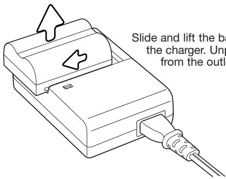
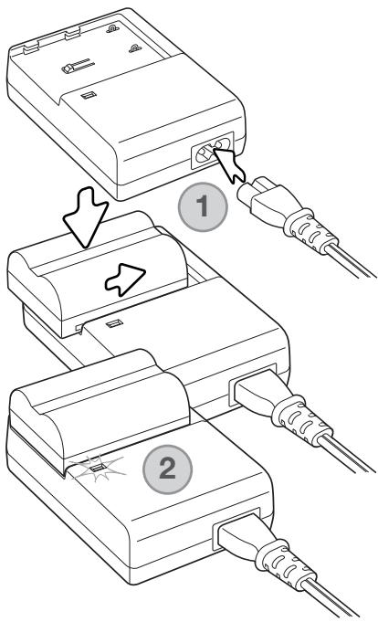
Before the camera can be used, the lithium-ion battery must be charged. Before charging the battery, read the safety warnings on page 4 of this manual. Only recharge the battery with the supplied battery charger. The battery should be recharged before each shooting session. See page 170 for battery care and storage.
Plug the power cord into the back of the charger unit (1). Plug the other end of the cord into a live household outlet. The included AC cord is designed for the current of the sales region. Only use the cord in the region it was purchased. For more on the AC cable, see page 167.
With the battery contacts toward the charger, align the channels on the bottom of the battery with the tabs on the charger unit. Slide the battery into the unit.
The indicator lamp (2) will glow to show the battery is charging. The lamp will go out when the battery is charged. Charging time is approximately 150 minutes.
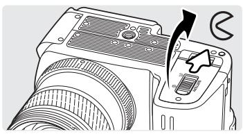
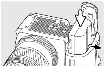
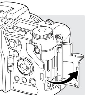
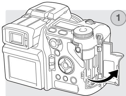
Installing and Changing the Battery
This digital camera uses one NP-400 lithium-ion battery. Before using the battery, read the safety warnings on pages 4 of this manual. When replacing batteries, the camera should be off.
natural_image
Diagram of a DSLR camera with a tool inserted, showing no text or symbols on the device itselfOpen the battery-chamber door by sliding the battery-chamber lock to the open position.
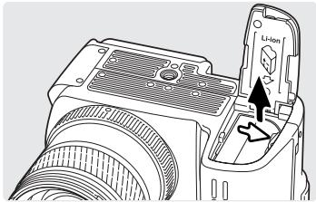
Insert the battery with the battery contacts first. Insert the battery so that it slides past the battery latch in the chamber. Push the battery into the chamber until the latch clicks into place.
natural_image
Technical line drawing of a DSLR camera with lens and external housing (no text or symbols)To remove a battery, slide the battery latch to the side of the battery chamber; the battery will spring out.
natural_image
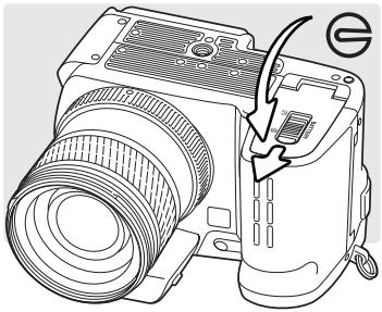
Line drawing of a camera with lens and external components, no text or symbols presentClose the battery-chamber door and slide the battery-chamber lock to the closed position.
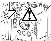
Battery Condition Indicator
This camera is equipped with an automatic battery-condition indicator. When the camera is on, the indicator appears on the data panel and monitors. The monitor indicator will change from white to red when battery power is low. If the data panel and monitors are blank, the battery may be exhausted.

Full-battery indicator - the battery is fully charged. This indicator is displayed for five seconds on the monitors when the camera is turned on. The indicator remains on the data panel.

Low-battery warning - battery power is very low, but all functions are operational. The battery should be replaced as soon as possible. This warning automatically appears and remains on the display until the batteries are changed.

natural_image
Pure electrical circuit lines without any symbolsBlinking low-battery warning - displayed on the data panel with no other icons. Power is insufficient for camera operation. The shutter will not release. Replace or recharge the battery immediately.
Auto Power Save
To conserve battery power, the camera will turn off the monitors and unnecessary functions if an operation is not made within three minutes. The data panel remains on. To restore power, press the shutter-release button partway down or press the main switch. The length of the auto-power-save period can be changed in section 3 of the setup menu (p. 129).
If an operation is not made within thirty minutes, the camera will shut down. Press the main switch to restore power.
External Power Supplies (sold separately)
The AC Adapter allows the camera to be powered from an electrical household outlet. The AC Adapter is recommended when the camera is interfaced with a computer or during periods of heavy use. AC Adapter model AC-1L is for use in North America and Japan, and AC-11 is for use in all other areas.
The External High-power Battery Pack Kit EBP-100 is a portable power source and significantly extends the operating time of the camera. The kit contains a high-power lithium-ion battery, holder, and charger. The battery, holder, and charger are also available separately.
Always turn off the camera and confirm the access lamp is not lit before changing between power supplies.
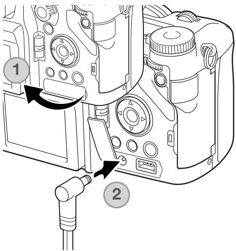
Remove the DC terminal cover from the right (1). The cover is attached to the body to prevent loss.
Insert the mini plug of the AC adapter or battery pack into the DC terminal (2).
Insert the AC adapter plug into an electrical outlet.
Inserting and Changing a Memory Card
Always turn off the camera and confirm the access lamp is not lit before inserting or removing a memory card, otherwise the card may be damaged, and data lost.
natural_image
Technical line drawing of a DSLR camera with internal components and an arrow indicating a directional movement (no text or symbols present)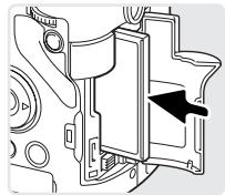
natural_image
Mechanical assembly diagram showing internal components with an arrow indicating a specific part (no text or symbols present)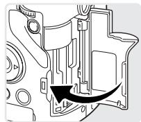
natural_image
Mechanical assembly diagram showing internal components with a black arrow indicating a specific part (no text or labels present)A memory card must be inserted for the camera to operate. If a card has not been inserted, a no-card warning will be displayed on the monitors. Type I and II CompactFlash cards and IBM Microdrives are compatible with this camera. For memory card care and handling, see page 169.
Open the card-slot door in the direction indicated.
Insert a memory card all the way into the card slot. Insert the card so the face is toward the front of the camera. Always push the card in straight. Never force the card. If the card does not fit, check that it is oriented correctly.
Close the card-slot door.
natural_image
Line drawing of a DSLR camera with internal components and a directional arrow indicating motion (no text or symbols)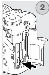
natural_image
Line drawing of a digital camera module with an arrow pointing to the internal component (no text or symbols present)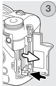
natural_image
Diagram of a camera module with an arrow indicating a component, no text or symbols present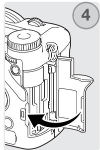
natural_image
Diagram of a camera module with an arrow indicating rotation or movement (no text or symbols present)To eject a card, open the card-slot door (1), and press and release the card-eject lever to extend it (2).
Press (3) the card-eject lever to eject the card (3). The card can now be pulled out. Take care when removing the card as it becomes hot with use. The card-eject lever should remain inside the camera body. If it extends, push it into the camera.
Insert a new memory card and close the card-slot door (4).
A memory card used in another camera may have to be formatted before being used. If the unable-to-use-card message appears, the card should be formatted with the camera. A memory card can be formatted in section 1 of the playback menu (p. 120). When a card is formatted, all the data on the card is permanently erased. If the card-error message appears, press the central button of the controller to close the window; check the Konica Minolta web site for the latest compatibility information:
North America: http://www.konicaminolta.us/ Europe: http://www.konicaminoltasupport.com
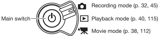
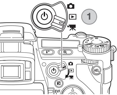
Turning on the Camera
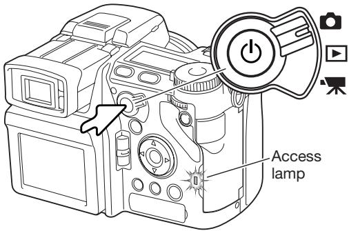
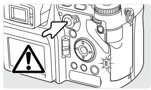
Press the main switch to turn on the camera. The access lamp glows briefly and an audio signal sounds to indicate the power is turned on. The audio signal can be turned off with the setup menu (p. 141).
If the camera shuts down immediately after it is turned on, the battery power is low. See page 22 on how to charge the battery.
Press and hold the main switch to turn the camera off.
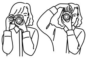
Handling the Camera
While using the electronic viewfinder (EVF) or LCD monitor, grip the camera firmly with your right hand while supporting the body with the palm of your left hand. Keep your elbows at your side and your feet shoulder-width apart to hold the camera steadily.
natural_image
Line drawing of two people using binoculars (no text or symbols)Adjusting the Viewfinder and Monitor
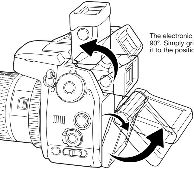
The electronic viewfinder can be tilted between 0^ and 90^ . Simply grip the finder between your fingers and move it to the position desired.
The LCD monitor can be tilted between -20^ and +90^ . Grip the top of the monitor and pull to tilt it down. The bottom of the monitor can then be swung up.
Always store the camera with finder and monitor against the body.
Diopter adjustment
The EVF has a built-in diopter that can be adjusted between -3.5 to +1.5. While looking through the EVF, turn the diopter-adjustment dial until the viewfinder image is sharp.
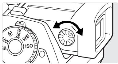
Setting the Date and Time
After initially inserting a memory card and battery, the camera's clock and calendar must be set. When images are recorded, the image data is saved with the date and time of recording. Depending on the region, the menu language may also have to be set. To change the language, see the camera notes on the following page.
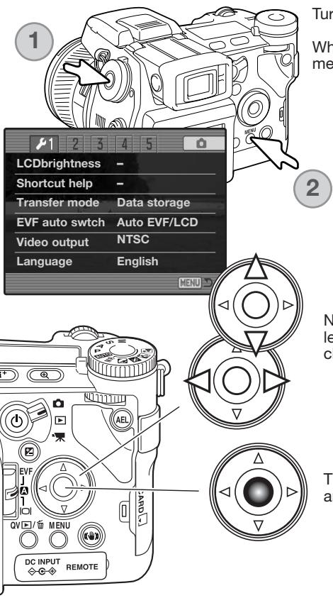
Turn on the camera.
While holding down the function button (1), press the menu button (2) to open the setup menu.
Navigating the menu is simple. The up/down and left/right keys of the controller move the cursor and change settings on the menu.
The central button of the controller selects menu options and sets adjustments.
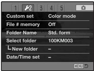

Use the right controller key to highlight the 2nd tab at the top of the menu.

Use the down key to highlight the date/time-set menu option.

Press the right key. "Enter" will appear on the right side of the menu.


Press the central button to display the date/time setting screen.
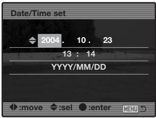
Date/Time setting screen

Use the left and right keys to select the item to be changed.

Use the up and down keys to adjust the item.

Press the central button to set the clock and calendar. The setup menu will be displayed.
Camera notes
For customers in certain areas, the menu language must also be set. Highlight the language option in section 1 of the setup menu. Press the right key to display the language settings. Using the up/down keys, highlight the desired language. Press the central button to set the highlighted language; the setup menu will be displayed in the selected language.
Basic Recording
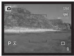
Setting the Camera to record Images Automatically
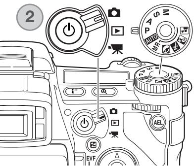

Set the exposure dial to the program (P) position (1). Confirm the mode switch is in the recording position (2).
All camera operations are now fully automatic. The autofocus, exposure, and imaging systems will work together to make photography effortless.
The Auto exposure mode acts like the program mode, except that the many of the recording functions are reset each time it is selected, see page 52 for more information.
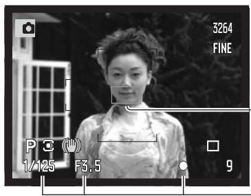
EVF and LCD Monitor Display
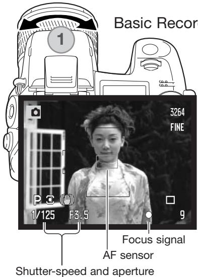
Basic Recording Operation
Use the zooming ring to frame the subject (1). The effect of the zoom is immediately displayed in the viewfinder (EVF) and LCD monitor.
Place the subject within the focus frame. For off-center subjects, use the focus-lock function (p. 34).
The subject must be within the focus range of the lens: 0.5m (1.6ft) - ∞. For subjects closer than 0.5m (1.6ft), use the macro function (p. 49).
Press the shutter-release button partway down (2) to lock the focus and exposure.
When the focus is set, an AF sensor will briefly appear in the live image to indicate the point of focus. The focus signals (p.35) on the monitors will confirm that the image is in focus. If the focus signal is red, the camera was unable to focus on the subject. Repeat the previous steps until the signal is white. The shutter speed and aperture value will change from white to black indicating the exposure is locked.
Press the shutter-release button all the way down (3) to take the picture. The access lamp glows indicating the image data is being written to the memory card. Never remove a card while data is being transferred.
Focus Lock
The focus-lock function is used when the subject is off-center and outside the focus frame. Focus lock may also be used when a special focusing situation prevents the camera from focusing on the subject.
Place the subject within the focus frame. Press and hold the shutter-release button partway down.
- The focus signals will indicate that the focus is locked. The shutter speed and aperture value will change from white to black indicating the exposure is locked.
- When the focus is set, an AF sensor will briefly appear on the live image to indicate the point of focus.
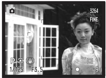
Without lifting your finger from the shutter-release button, recompose the subject within the image area. Press the shutter-release button all the way down to take the picture.
Automatic Monitor Amplification
In extremely low-light conditions when the camera-sensitivity gain has reached its limit, the automatic monitor-amplification function will intensify the EVF and LCD monitor image. The live image will be brighter, however, the display will be black and white. This will have no effect on the final color image. This function can be turned off in section 3 of the recording menu (p. 104).
Focus Signals
This digital camera has a quick, accurate autofocusing system. The focus signals in the lower right corner of the EVF and LCD monitor indicate the focus status. For more information on autofocus modes, see p. 46.
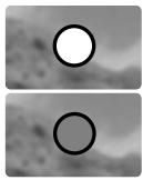
natural_image
Two identical circular shapes with black outlines on a blurred grayscale background (no text or symbols)White focus indicator - focus confirmed.
Red focus indicator - the subject is too close or a special situation is preventing the AF system from focusing. The shutter can be released.
If the AF system cannot focus on a certain subject, focus lock can be used with an object at the same distance as the main subject or the camera can be focused manually (p. 34).
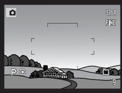
Special Focusing Situations
The camera may not be able to focus in certain situations. If the autofocus system cannot focus on a subject, the focus icon will turn red. In this situation the focus-lock function can be used to focus on another object at the same distance as your main subject, and then the image can be recomposed to take the picture.

The subject is too dark.
natural_image
Grayscale landscape photo showing a rural path with houses, trees, and distant buildings under a cloudy sky (no text or symbols)The subject in the focus frame is low in contrast.

Two subjects at different distances overlap in the focus frame.

natural_image
Illustration of a girl standing in front of a ship with ships and clouds in the background (no text or symbols)The subject is near a very bright object or area.
Using the Built-in Flash
In low-light conditions or indoors, the flash is needed to illuminate the subject and reduce blurring through camera shake. The flash can also be used as a fill light in direct sunlight to soften harsh shadows. Always remove the lens hood when using the built-in flash; the hood may cast a shadow if mounted.
natural_image
Diagram of a mechanical component with directional arrows indicating motion (no text or symbols)To use the flash, simply pull up the unit by the tabs on each side. The flash position must be set manually, and once up, the flash unit will always fire regardless of the amount of ambient light. The following indicators will appear in the upper left corner of the EVF and LCD monitors to show the flash status.
| (A425) | The red flash indicator appears when the flash is charging. |
| (645X1) | The white flash indicator appears when the flash is ready to fire. |
| (A423) | After taking a picture, the OK indicator appears briefly if the flash properly exposed the subject. |
| (6740) | Flash warning. In backlit situations, a white indicator appears to recommend the use of the flash. |
Flash Range - Automatic Operation
The camera will automatically control the flash output. For well-exposed images, the subject must be within the flash range. Because of the optical system, the flash range is not the same at the lens' wide-angle position as it is at the telephoto position.
Wide-angle position
0.5m \~ 3.8m (1.6 ft. \~ 12.5 ft.)
Telephoto position
0.5m \~ 3.0m (1.6 ft. \~ 9.8 ft.)
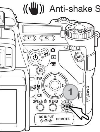
Anti-shake System
The Anti-shake system minimizes the effect of camera shake, a slight blurring caused by subtle hand motion. Camera shake is more pronounced at the telephoto setting than at the wide-angle. Anti-shake is employed when the shutter speed falls below a certain limit depending on the focal length in use. The effectiveness of Anti-shake depends on the shutter speed in use and the degree of shaking. The system may not work with moving subjects or when the camera is panned.
When the system is active, the Anti-shake button glows (1). Anti-shake can be turned off and on by pressing the button.
Frame the subject as described in the basic operation section. Press the shutter-release button partway down to focus and set the exposure; an Anti-shake indicator is displayed when active. Confirm the image has stabilized on the monitor and press the shutter-release button all the way down to take the picture.

The blue indicator appears when the Anti-shake system is activated.
The yellow indicator appears when the Anti-shake system is activated, but the shutter speed is too slow for it to be effective.
When Anti-shake is off, the white indicator appears to warn the shutter speed is too long for the camera to be safely handheld.
If the yellow or white warnings appears, place the camera on a tripod, use the built-in flash, increase the camera sensitivity (ISO) (p. 74), or use a wide-angle zoom position. If the Anti-shake indicator turns red, the camera is overheating because of operating and ambient temperatures. The Anti-shake system will turn off automatically. Allow the camera to cool before using Anti-shake.
The Anti-shake system is less effective at short subject distances or when using the macro function (p. 49). The use of a tripod is recommended. Anti-shake is not effective with a tripod mounted camera; turn off the Anti-shake function to conserve power.
Movie Recording
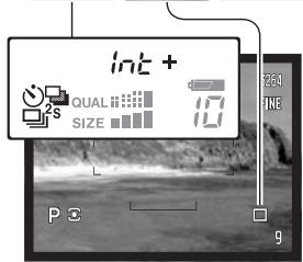
Set the mode switch to the movie-recording position (1). Before recording, the data-panel and monitor frame counters show the maximum time in seconds that can be recorded. The length of the movie clip depends on the image size and frame rate, and the space available on the memory card. The maximum recording time is 6 minutes with 544x408 30fps movies or 15 minutes with other size and frame-rate combinations; low light levels can shorten this time. Image size and frame rate is selected with the movie menu (p. 112). For more on movie recording, see page 114.

Place the subject in the center of the live image and press the shutter-release button partway down to set the focus. Use the focus signal to confirm focus.
Image size
Frame rate
Focus signal
Total recording time for the next movie clip.
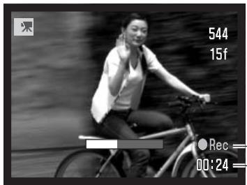
Recording time in seconds Recording indicator
Press the shutter-release button all the way down and release to start recording. The camera will continue to record until the recording time is used or the shutter-release button is pressed again. When recording, the monitor frame counter and status bar shows the recorded time.

Display Mode Switch
Located on the back of the camera, the display-mode switch controls which monitor is active. The three position switch allows the choice between automatic display and setting the display to the EVF or LCD monitor.
Auto display - the camera will automatically change between displaying the live image in the EVF or on the LCD monitor. The EVF's eye sensors monitor if the EVF is being used and switches the display location accordingly.

EVF DISPLAY - the live image will only be displayed in the electronic viewfinder. Under bright light, the image is easier to see in the EVF than on the LCD monitor.

LCD monitor display - the live image will only be displayed on the LCD monitor.
Basic Playback
Images can be viewed in the Quick View or playback modes. This section covers the basic functions in both modes. The playback mode has additional menu functions, see page 116.
To view images from the playback mode, turn the mode switch to the playback position.
To view images from the recording or movie recording modes, press the Quick View / delete button.
Single-frame Playback and Histogram Display
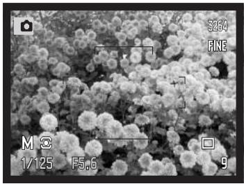
![Time of capture 13:24 2004.02.27 [0024/0093] Date of capture 3264 FINE Image size (p. 82) Image quality (p. 82) 3264 FINE 1/2000 Aperture value F3.5 -0.7 Shutter speed Degree of exposure compensation (p. 59) AWB ISO200 KMO03 White-balance setting (p. 70) Sensitivity setting (p. 74) Folder name (p. 137) Folder number - image file number 2004.02.27 Histogram (p. 19) Frame number/ total number of images](/content/2025/01/139770/images/4736fa0ce64e6a9744edc6f0464e49c755f2b22f08f44fe2754f3d5ccdf52e06.jpg)
Viewing Images and Histogram
When in the Quick view or playback mode, use the left/right keys of the controller to scroll through the images on the memory card.
To view the histogram of a still image, press the up key. Press the down key to return to single-frame playback.
- To return to a recording mode from Quick View, press the menu button.
natural_image
Black-and-white photo of a child looking at a landscape, with a camera control panel visible on the right (no readable text or symbols in the scene)Rotating Images
Press the down key of the controller to rotate a displayed image 90^ left, 90^ right, or horizontally.
Deleting Single Images
The displayed image can be deleted. Once deleted, an image cannot be recovered.

To delete a displayed image, press the QV/delete button; a confirmation screen will appear.

Use the left/right keys to highlight "Yes." "No" will cancel the operation.

Press the controller to execute the command on the confirmation screen. The camera will return to playback mode.
![Delete this frame? Yes No 13:24 2004.02.27 [0024/0093]](/content/2025/01/139770/images/0bd4e216aed24b8a7ad05981de8bc7f1a4041beecb03adaf1c8a991b2930dfc2.jpg)
Confirmation screen
Changing the Quick View & Playback Display
The display-information button controls the display format. Each time the button is pressed, the display cycles through to the next format: full display, image only, index playback.
flowchart
graph TD
    A["Full display"] --> B["Image only"]
    B --> C["Index playback"]
    C --> D["2004.07.27"]
    D --> E["[0024/0093"]]
    E --> F["2004.02.27"]
    F --> G["5637"]
In index playback, the four-way keys of the controller will move the yellow border to the adjacent image. When the image is highlighted with the border, the date of recording, voice-memo indicator, the lock and printing status, and the frame number of the image are displayed at the bottom of the screen. The highlighted image can be deleted using the QV/delete button (p. 41) or an accompanying audio track can be played by pressing the central button of the controller. When the display information button is pressed again, the highlighted image will be displayed in the single-frame playback mode. A nine or four image index can be displayed. The index-playback format can be changed in section 1 of the playback menu (p. 121).
![15:24 2004.02.27 [00034/0003]](/content/2025/01/139770/images/cbe8a25050690a8bc59df163da07ba040e285e7919b5020e63966b2270089e37.jpg)
Enlarged Playback
In single-frame playback, a still image can be enlarged for closer examination from 1.2X. The maximum magnification depends on image size from 2X for 640X480 size images to 10.2X for 3264X2448 images. RAW and TIFF images cannot be enlarged.
With the image to be enlarged displayed, press the magnification button (1).
natural_image
Close-up of a mechanical device with a scroll and zoom tool, no visible text or symbols
Use the up/down keys of the controller to adjust the magnification. The degree of magnification is displayed on the monitors.
Press the central button of the controller to switch between the zoom and scroll functions. The scroll arrows or magnification display will turn blue to indicate the active function.

natural_image
Close-up of a glass ink bottle and a mechanical component on a wooden surface, with no visible text or symbols.

Use the four-way key to scroll the image. Press and hold the four-way key to scroll continuously. The locator shows the area of the image being viewed. The front and rear control dials can change the magnification. Press the menu or magnification button to exit the enlarged playback mode.
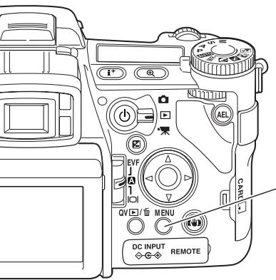
Press the display-information button (i+) to hide or show the guidance bar and display indicators.
Viewing Movies
Movies can be played back on the camera. Movie files are indicated by an indicator at the bottom of the display.
![Play 13:24 2004.02.27 [0024/0093]](/content/2025/01/139770/images/886fa79e1268e5fb5ff993eae2f6433fbdf87ddbcd807a84d2b651ffcdd61f8f.jpg)

Press the center of the controller to play back the file.
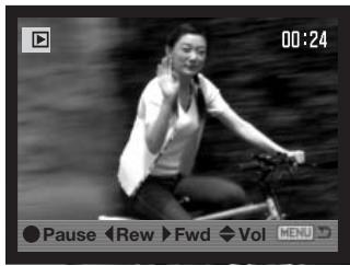

Press the controller to pause the movie; pressing the controller again will resume the playback.

Use the left/right keys of the controller to rewind or fast forward the movie clip.

Use the up/down keys to adjust the volume of the audio track.
When the movie is paused, pressing the up/down keys will jump to the first or last frame of the movie clip.
- To cancel the playback, press the menu button.
The guidance bar and display indicators can be hidden or shown by pressing the display-information button (i+).
Advanced Recording
This section contains detailed information on the camera's recording functions and operation. Read the sections pertaining to your interest and need.
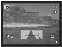
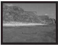
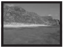
Display-information Button
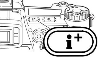
The display-information button controls what information is displayed with the live image. Each time the button is pressed, the display cycles to the next format: standard display, real-time histogram, focus frame, and live image only.
natural_image
Grayscale landscape photo showing a coastal cliff with no visible text or symbols, including a scale bar and camera settings (no readable text content)Standard display
natural_image
Grayscale landscape photo showing a rocky outcrop with a silhouette of a mountain in the foreground (no text or symbols visible)Real-time histogram
natural_image
Grayscale landscape photo showing a rocky cliff with a small water body and a scale bar (no text or symbols visible)Focus frame only
natural_image
Black-and-white landscape photo of a rocky cliffside with a body of water and distant hills (no text or symbols visible)Live image only
The real-time histogram shows the approximate luminance distribution of the live image. This histogram will not be accurate when the monitor image is amplified (p. 34, 104), or the built-in or a compatible Minolta flash unit is used. The histogram of a recorded image may not show the same distribution as the real-time histogram.
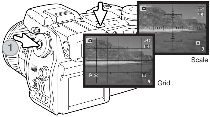
To display a grid or scale over the display formats, press and hold the function button (1) and press the display-information button to cycle through the options: grid, scale, and off.
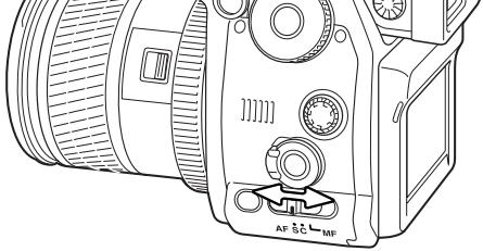
Focus-mode Switch
Single-shot AF (Autofocus), continuous AF, and manual focus is set with the focus-mode switch. Slide the switch to select the appropriate focus mode.
natural_image
Technical line drawing of a DSLR camera with no visible text or symbols
Single-shot AF - a general purpose autofocusing mode. Its operation is described in the basic recording section.

Continuous AF - used for photographing moving subjects. The camera continuously tracks and focuses on the subject.
Place the focus area on the subject. The four-way key of the controller can be used to move the area anywhere in the live image for off center subjects.
Press the shutter-release button partway down to engage the subject lock; the focus signal will confirm focus. If the subject moves or the camera is panned, the focus area will follow the subject. Focus and exposure will change as the subject moves and lighting conditions change.
Press the shutter-release button all the way down to take the picture. When the shutter button is released the focus area returns to the center of the live image. Subject tracking can be disabled and AE lock can be activated in section 4 of the recording menu (p. 80). Subject Tracking AF may not be effective under low light.
Continuous AF focus signal

Manual focus - the MF indicator is displayed in the lower right corner of the monitors to indicate the focus mode.
Use the focusing ring at the rear of the lens barrel to focus. Always use the monitor image to confirm focus. The approximate object distance from the CCD is displayed near the frame counter. The Flex Digital Magnifier (p. 105) can be used to enlarge the live image to judge sharpness.
Approximate location of the CCD plane
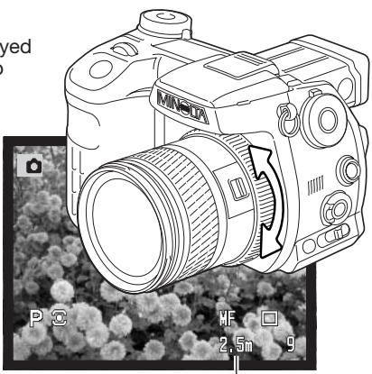
natural_image
Line drawing of a MINERA DSLR camera with lens and adjustment arrows, shown against a blurred floral background (no text or symbols on the device itself)Object distance
natural_image
Front view of a DSLR camera with a close-up of a historic cathedral at dusk, showing no visible text or symbols.Magnification display
Digital Zoom
The digital zoom doubles the lens magnification. The digital zoom cannot be used with RAW image quality, UHS continuous advance, or movie recording.
Press the magnification button on the back of the camera. The effect is immediate and X2.0 is displayed in top right corner of the live image. Pressing the magnification button a second time cancels the digital zoom.
When an image is taken with the digital zoom, the final image size depends on the image-size setting on the camera. 3264 X 2448, 2560 X 1920, 2080 X 1560, and 1600 X 1200 size images are resized to 1600 X 1200. 3264 X 2176 images are resized to 1600 X 1064. The pixel dimension of 640 X 480 size images do not change.
Flex Focus Point
The Flex Focus Point (FFP) is a powerful tool for off-center subjects. It can be moved to any point in the image area. The FFP cannot be used with the digital zoom or movie recording.
Press and hold the center button of the controller to activate the Flex Focus Point; the wide focus frames are replaced with a central cross.
natural_image
Black-and-white photo of a stone arch bridge over a river with trees and a building in the background (no visible text or symbols)Use the controller's four-way keys (1) to move the Flex Focus Point in the live image.

natural_image
Symmetrical geometric diagram with four arrows pointing outward from a central circle (no text or symbols)
natural_image
Black-and-white photo of a stone bridge over a water body with trees and a building in the background (no readable text or symbols)Press the shutter-release button partway down to focus; the FFP turns red briefly to confirm focus.

natural_image
Symmetrical circular diagram with concentric rings and directional arrows, no text or symbols presentPressing the central button of the controller returns the focus point to the center of the image area. To return to the wide-focus frames, press and hold the button until the frame lines appear.
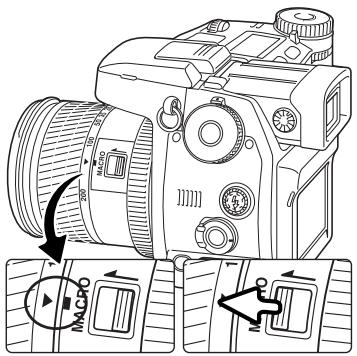
Macro Mode
The macro mode is used for close-up photographs of small objects. The built-in flash cannot be used with macro mode. The use of a tripod is recommended.
Align one of the arrows on the zooming ring with the index next to the macro switch and slide the switch forward. The lens must be zoomed to the wide-angle or telephoto position for the macro switch to engage. The zooming ring is locked at the wide-angle position. At the telephoto position, the zooming ring can move slightly to make fine adjustments to image size.
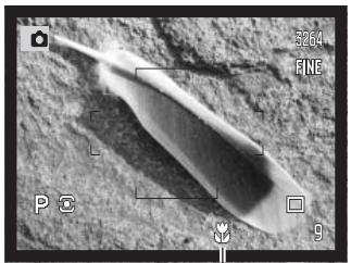
The macro indicator is displayed in the lower right corner of the monitors. Make sure the subject is within the macro focusing range:
Wide-angle position
0.3 \~ 0.6m (12 \~ 24 in.)
Telephoto position
0.25 \~ 0.6m (10 \~ 24 in.)
Approximate location of the CCD plane
natural_image
Grayscale image of a pointed, elongated object on a textured surface, with no visible text or symbols.Macro-mode indicator
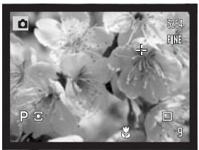
Shooting tips
Because of the high image magnification, hand holding cameras during close-up photography is very difficult. When possible, use a tripod.
Use the Flex Focus Point to specify the area to be in focus. Because depth of field (the area in focus) is narrow in close-up photography, using focus lock with off-center subjects can cause minor errors which are exaggerated at high magnifications.
natural_image
Close-up grayscale photo of flower petals with visible texture and no text or symbols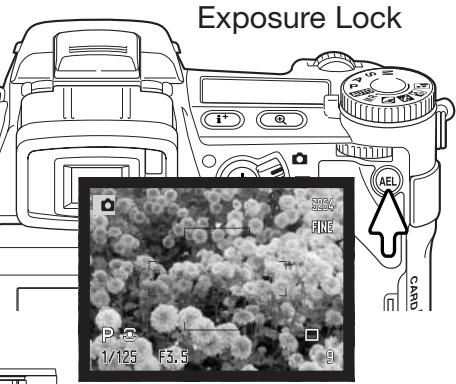
The AE lock button locks the automatic exposure system. This function allows the exposure to be set by a gray card or reference target outside the scene. When using flash in the P or A exposure modes, slow-shutter sync is activated by this button (p. 87). The operation of the AE lock button can be customized in section 1 of the recording menu (p. 94).
Press and hold the AE lock button to lock the exposure; the shutter speed and aperture monitor displays turns black; releasing the button cancels the setting. Frame the subject and press the shutter-release button partway down to lock focus.
Exposure-mode Dial
The exposure-mode dial is used to select traditional exposure modes as well as subject programs that optimize camera settings to specific shooting conditions. Camera settings saved in the camera can also be recalled with this dial. Simply turn the dial to the appropriate position.
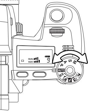
M Manual exposure (p. 56)
S Shutter priority (p. 55)
A Aperture priority (p. 54)
P Program exposure (p. 51)
AUTO Auto recording (p. 52)
MR Memory recall (p. 73)
Portrait subject program (p. 58)
Sports action subject program (p. 58)
Sunset subject program (p. 58)
Night portrait subject program (p. 58)
Program - P
Program exposure is set with the exposure-mode dial (p. 50). The program AE uses luminance and focal-length information to calculate exposures. This allows the photographer to shoot without worrying about exposure settings. The shutter speed and aperture values of the exposure are displayed on the monitors and data panel. If the brightness level of the scene is outside the exposure control range of the camera, the shutter-speed and aperture displays turn red on the monitors and blink on the data panel.
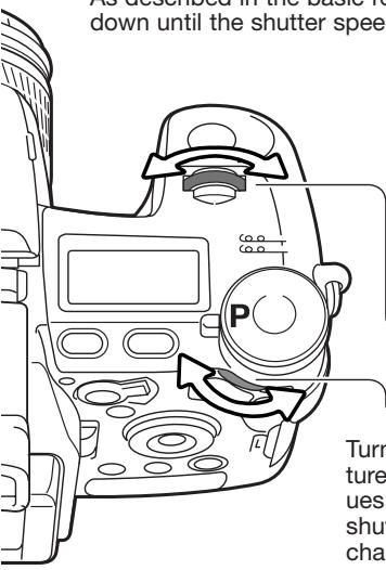
PROGRAM SHIFT - Ps/Pa
Program-shift function allows adjustment to the shutter-speed/aperture combination determined by the camera. The built-in flash cannot be used with program shift. The camera gives priority to the flash exposure; once the flash is raised, any changes made with program shift will be canceled.
As described in the basic recording operation (p. 33), press the shutter-release button partway down until the shutter speed and aperture value are displayed.
natural_image
Black-and-white photo of a stone arch bridge over a water body with trees and a building in the background (no readable text or symbols)
natural_image
Black-and-white photo of a stone arch bridge over water with trees and a railing, no visible text or symbols.Turn either the front or rear control dial to shift the shutter speed and aperture combination; each combination gives the equivalent exposure. The values are shifted in 0.3Ev or 1/3 stop increments. The front dial changes the shutter speed (Ps) and the rear dial changes the aperture (Pa). If the lighting changes, the shifted value remains fixed and the other display changes to compensate for the required exposure.
Auto Recording
Auto recording is set with the exposure-mode dial. Auto recording is the same as the program exposure mode (p. 51), except that when the camera is on, if the exposure mode dial is turned to or from the auto position, the auto exposure mode is reset. Turning the camera off will not reset the mode. The following functions are reset:
| Display mode | Standard | p. 45 |
| Exposure compensation | 0.0 | p. 59 |
| Flash compensation | 0.0 | p. 59 |
| Drive mode | Single-frame advance | p. 61 |
| Anti-shake | On | p. 37 |
| White balance | Auto | p. 70 |
| White-balance shift | 0 | p. 70 |
| Custom white balance | Memory reset to daylight | p. 70 |
| Camera sensitivity (ISO) | Auto | p. 74 |
| Metering mode | Multi-segment | p. 69 |
| Contrast compensation | 0 | p. 79 |
| Color-saturation compensation | 0 | p. 78 |
| Filter | 0 | p. 79 |
| Focus area | Wide focus frames | p. 33 |
| Image size | 3264 x 2448 | p. 82 |
| Image quality | Fine | p. 82 |
| Flash mode | Fill flash | p. 86 |
| Flash metering mode | ADI | p. 92 |
| Flash output (Manual) | 1/4 | p. 92 |
| AEL button | AE hold | p. 94 |
| Interval | 1 minute | p. 96 |
| Number of frames (Interval) | 2 | p. 96 |
| Start time (Interval) | 0.0 hr | p. 96 |
| Bracket setup | 0.3Ev step | p. 96 |
| Data imprinting | Off | p. 98 |
| Imprint to | Image and Exif | p. 98 |
| Instant playback | Off | p. 100 |
| Voice memo | Off | p. 101 |
| Color mode | Natural color (sRGB) | p. 102 |
| Sharpness | Normal | p. 97 |
| Noise reduction | On | p. 103 |
| Monitor amplification | Auto | p. 104 |
| Monitor amplification - Manual exp. | Exposure priority | p. 104 |
| Magnification button | Digital zoom | p. 105 |
| DSP setup | DSP (Digital Subject Programs) | p. 106 |
| Subject tracking AF | On | p. 106 |
| AE Lock | Off | p. 94 |
| Spot AE area | Center spot | p. 107 |
| Direct manual Focus (DMF) | Off | p. 107 |
| EVF mode | Quality 30fps | p. 108 |
| Custom setup | Depth of field preview | p. 136 |
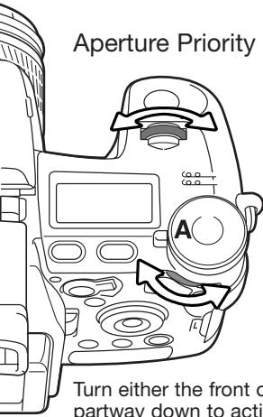
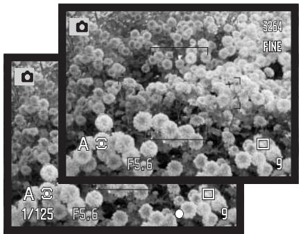
Aperture Priority - A
Aperture priority is set with the exposure-mode dial (p. 50). The photographer selects the aperture and the camera sets the appropriate shutter speed to ensure the correct exposure. When A mode is selected, the aperture display on the monitors turns blue.
natural_image
Microscopic view of spherical flowers with measurement annotations (no readable text or symbols)Turn either the front or rear control dial to change the aperture. Press the shutter-release button partway down to activate the exposure system; the corresponding shutter speed is displayed.
The aperture values can be changed by 0.3Ev or 1/3 stop increments between f/2.8 and f/11 at the lens' wide-angle position and f/3.5 to f/11 at the lens' telephoto position. If the aperture value is beyond the shutter-speed range, the shutter-speed display will blink on the data panel and turn red on the monitors.
With the camera sensitivity (ISO) set to auto (p. 74), the shutter speed may not change when the aperture is adjusted because the shutter speeds can be adjusted in fine steps.
Camera Notes
When photographing scenes with very bright objects such as the sun at large apertures (f/2.8 or f/3.5), streaking may be apparent in the image. Black areas caused by a loss of data may result. In these situations, stop down the aperture or use neutral density filters to minimize the effect.
Do not point the camera toward the sun for prolonged periods of time. The intensity of the sun could damage the CCD. Between exposures, turn off the camera or cover the lens.
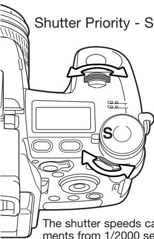
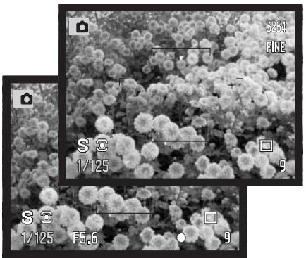
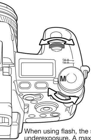
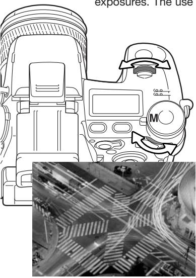
Shutter Priority - S
Shutter priority is set with the exposure-mode dial (p. 50). The photographer selects the shutter speed and the camera sets the appropriate aperture to ensure correct exposure. When S mode is selected, the shutter speed display on the monitors turns blue.
Turn either the front or rear control dial to change the shutter speed. Press the shutter-release button partway down to activate the exposure system; the corresponding aperture will be displayed.
The shutter speeds can be changed by 1/3 stop increments from 1/2000 second, see below. If the shutter speed is beyond the aperture range, the aperture display will blink on the data panel and turn red on the monitors.
natural_image
Black-and-white photo collage showing flower clusters with camera and measurement overlays (no readable text or symbols)When using flash, the shutter speed should be set to the flash duration of the flash unit to prevent underexposure. A maximum shutter speed of 1/1000s is recommended when using the built-in flash and 1/250s when using a compatible Minolta flash unit.
The yellow and white Anti-shake indicators do not appear in S mode.
SHUTTER-SPEED RANGE AND CAMERA SENSITIVITY (ISO)
The maximum shutter speed or bulb exposure depends on the camera sensitivity (ISO) setting. ISO can is changed with the function dial. For more about camera sensitivity, see page 74.
| ISO Settings | Shutter speed |
| 64 | 30 seconds |
| 100 | 30 seconds |
| 200 Auto | 15 seconds |
| 400 | 8 seconds |
| 800 | 4 seconds |
Manual Exposure - M
Manual exposure mode allows individual selection of shutter speeds and apertures. This mode overrides the exposure system giving the photographer total control over the final exposure. Manual exposure is set with the exposure-mode dial (p. 50).
The shutter speeds and aperture values can be changed in 1/3 stop increments. The shutter speed range in manual exposure mode is 30 to 1/2000 second including bulb (p. 57). The camera sensitivity is set to ISO 100, but can be changed with the function dial (p. 74). The maximum shutter speed changes with sensitivity, see page 55.
As changes are made to the exposure, the effect will be visible on the monitors. The shutter-speed and aperture display will blink on the data panel and turn red on the monitors if the image is extremely under or overexposed. If the monitors are black, increase the exposure until the image is visible; decrease the exposure if the monitors are white. The recording menu can be used to constantly display a live image regardless of the exposure setting (p. 104).
To set the shutter speed, turn the front control dial. To set the aperture, turn the rear control dial. The appropriate display will turn blue as the exposure is changed.
To use manual shift, press and hold the AEL button while turning the front control dial; both the shutter speed and aperture are changed without affecting the total exposure.
natural_image
Black-and-white close-up of a flower field with no visible text or symbolsWhen using flash, the shutter speed should be set to the flash duration of the flash unit to prevent underexposure. A maximum shutter speed of 1/1000s is recommended when using the built-in flash and 1/250s when using a compatible Minolta flash unit.
The operation of the manual exposure mode can be customized with the setup menu (p. 145). The yellow and white Anti-shake indicators do not appear in M mode.
Bulb Exposures
Bulb photographs can be taken in the manual-exposure mode (M). The maximum exposure time depends on the camera sensitivity setting, see page 55. The use of a tripod and a remote cord is recommended for bulb exposures. The camera's exposure system cannot be used to calculate bulb exposures. The use of a separate light meter is recommended.
natural_image
Diagram of a camera with exposure device and circuit board overlay (no text or symbols)Use the front control dial to decrease the shutter-speed until “bulb” is displayed.
Use the rear control dial to set the appropriate aperture required for the exposure.
To take the picture, press and hold the shutter-release button for the duration of the exposure. Releasing the shutter button will end the exposure.
The monitors will be blank during the exposure. The shutter sound effect will signal the end of the exposure. The monitors will remain blank for up to 30 seconds while noise-reduction processing is applied to the image.
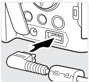
Attaching a Remote Cord (sold separately)
The optional remote cords (RC-1000S or RC-1000L) can be used to reduce vibrations from touching the camera during long exposures. Before using the cord, attach the ferrite core supplied with the camera as described on page 167.
Remove the remote-control terminal cover using the notch on the right side of the cover. The cover is attached to the body to prevent loss. Insert the plug of the cord into the terminal.
natural_image
Diagram showing a connector being inserted into a device panel, with no visible text or symbols.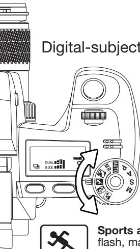
Digital-subject-programs
Digital subject programs optimize the camera's exposure, white-balance, and image-processing systems for specific conditions and subjects. Simply turn the exposure mode dial to select the appropriate subject program.

Portrait - optimized to reproduce warm, soft skin tones and a slight defocusing of the background. Most portraits look best at a telephoto setting; the longer focal length does not exaggerate facial features and the shallower depth of field softens the background. Use the built-in flash with strong direct sunlight or backlight to reduce harsh shadows.

Sports action - used to capture fast action by maximizing shutter speeds. When using a flash, make sure the subject is within the flash range (p. 75). The flash range can be extended by changing the camera sensitivity (p. 74). A monopod is more flexible and compact than a tripod when shooting events.

Sunset - optimized to reproduce rich, warm sunsets. When the sun is above the horizon, do not point the camera toward the sun for prolonged periods of time. The intensity of the sun could damage the CCD. Between exposures, turn off the camera or cover the lens.

Night portrait - for deep, subtle night scenes. When used with flash, the subject and background exposures are balanced. Use a tripod to eliminate blurring from camera shake. The flash can only be used with close subjects such as with a portrait of a person. When using the flash, ask your subjects not to move after the burst; the shutter will still be open for the background exposure.
Not all recording functions, such as the metering mode, can be changed when using Digital Subject Programs.
Exposure and Flash Compensation
The ambient light and flash exposure can be adjusted before the image is captured to make the final picture lighter or darker. Exposure can be adjusted by as much as ±2E_v in 1/3 increments (p.111). The exposure and flash compensation will remain in effect until it has been reset. For more on exposure and flash compensation, see page 110.
Adjustments to exposure must be set before the image is captured. When setting exposure or flash compensation, the change in Ev is shown on the data-panel aperture display and on the monitors. After the setting is made, the shutter-speed and aperture displays will indicate the actual exposure.
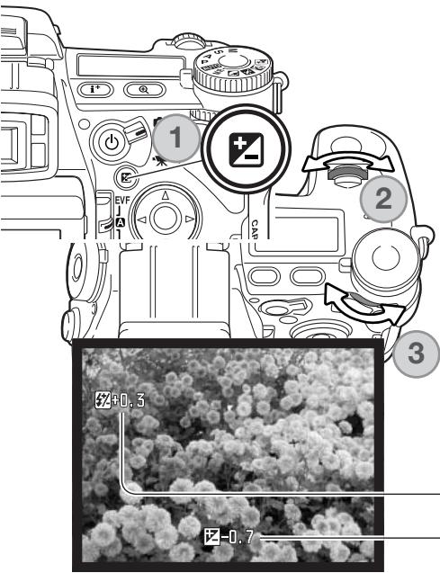
Press the exposure-compensation button (1).
Use the front control dial (2) to set exposure compensation. The indicators are enlarged when being adjusted.
Use the rear control dial (3) to set flash compensation.
Press the shutter-release button partway down or press the exposure-compensation button to complete the operation. The values will automatically be set if a change is not made for a few seconds. If any other value except 0.0 was set, an indicator will be displayed on the monitor as a warning. Also see camera notes on page 65.
-Flash compensation
Exposure compensation
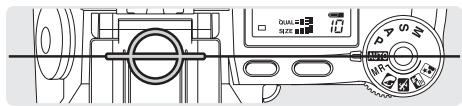
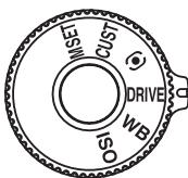
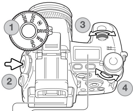
Using the Function Dial
The memory function, metering mode, drive mode, white balance, and camera sensitivity are controlled by the function dial. The custom position is for a designated menu function that can be set in section 2 of the setup menu. Only white balance can be set in the movie recording mode.
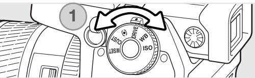
Turn the function dial to the mode to be changed (1).
Press the function button in the center of the dial (2). Turn the front control dial to change the mode (3). Use the rear control dial (4) to select between options of various functions like a 10-second and 2-second self-timer, or a specific custom white-balance register. Press the shutter-release button partway down or press the function button to complete the operation. Changes are displayed on the monitors. Also see camera notes on page 65.
Memory set - to store camera settings (p. 72).
Custom function - to set the function designated in section 2 of the setup menu (p.136).
Metering mode - changes the metering pattern (p. 69).
Drive mode - changes the method of image capture (p. 61).
White balance - changes between automatic, preset, and custom white balance (p.70).
ISO - changes camera sensitivity (p. 74).
Drive Modes
The drive modes control the rate and method of image capture. Indicators showing the selected drive mode appear on the data panel and monitors. The drive mode is set with the function dial (p. 60).
 | [04KY] | Single-frame advance - to take a single image each time the shutter-release button is pressed (p. 33). |
 | [7YXX] | Bracketing - to take a series of three images with differing exposure, contrast, saturation, or color (p. 62). |
 |  | Continuous advance - to take a series of three images when the shutter-release button is pressed and held (p. 64). |
 |  | High-speed continuous advance - to take a series of three images at approximately 2.7 frames per second (p. 64). |
 |  | UHS (Ultra High Speed) continuous advance - to take multiple 640 X 480 size images at approximately 7 frames per second (p. 64). |
| [DXZZ] |  | Interval - to take a series of images over a period of time (p. 66). |
 |  | Interval and time-lapse movie - to take a series of still images and a movie clip of a slow moving event (p. 66). |
 | [H5HO] | Self-timer - to delay the release of the shutter by 10 or 2 seconds. Used for self-portraits (p. 68). |
When a large amount of image data is captured in a short period, the camera's internal buffer memory becomes full; the frame counter turns yellow on the monitors. Time must be given for this data to be written to the memory card. Wait for the indicator to turn white before capturing more images.
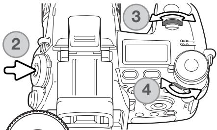
Bracketing
This drive mode makes a three image bracket of a scene. Bracketing is a method of taking a series of images of a static subject in which each image has a slight variation in exposure. Contrast, saturation, and filter brackets can also be made.
Turn the function dial to the drive mode position (1).
Press the function button in the center of the dial (2). Turn the front control dial to select the bracketing drive mode (3). Use the rear control dial (4) to switch between continuous-advance, single-frame advance, and Digital Effect brackets; the Digital Effect bracket depends on the position of the Digital Effect switch (p. 78). Press the shutter-release button partway down or press the function button to set the mode.
flowchart
graph TD
    A["C"] --> B["S"]
    B --> C["F"]
    B --> D["H"]
    B --> E["O"]
    C --> F["COL"]
    D --> G["Ent"]
Continuous-advance bracket - the order of the exposure bracket series is normal exposure (as indicated by the camera), underexposure, and overexposure. The exposure bracket is set to 0.3Ev increments, but can be changed to 0.5Ev increments in section 2 of the recording menu (p. 96). If the memory card is filled or the shutter button is released before the series has completed, the camera will reset and the entire bracket must be made again.
Single-frame advance bracket - the same as the continuous-advance bracket except that the shutter-release button must be pressed for each exposure. Focus does not lock with the first frame.
Digital Effect bracket - for filter, color saturation, or contrast brackets. Set the contrast, color saturation or filter to the desired level; the bracket series is from the Digital Effects Control setting to one unit under to one unit over. See the Digital Effects Control section on page 78 to set the contrast, color saturation, and filter.
Compose the picture as described in the basic recording section (p. 33). Press and hold the shutter-release button all the way down (1) to make the bracket series; three consecutive images will be captured. If single-frame advance bracketing is selected, the shutter-release button must be pressed for each exposure. If set to continuous AF (p. 46), the camera will continue to focus during a continuous bracket.
When using flash, TIFF, or RAW & JPEG, single-frame advance is employed. To make a flash bracket, raise the camera flash; the ambient exposure is not bracketed.
When exposure brackets are made in S exposure mode, the aperture controls the bracket. In A and M modes, the shutter speed controls the bracket; in M mode, pressing the exposure-compensation button during the bracket changes the exposure control to the aperture. The camera uses both the aperture and shutter speed control the bracket in P mode.
With a Digital Effect bracket, if the contrast or color saturation is set to the maximum or minimum level ( ±5 ), one bracket will be made at ±6 : +5, +4, +6. A RAW image cannot exceed the maximum and minimum levels and will contain two identical brackets: +5, +4, +5. A black and white Filter bracket is made to the settings before and after the set Filter (p. 79). If Filter 10 is selected, the bracket series will be 10, 9, 0.
Continuous Advance
Continuous-advance mode allows a series of images to be captured while holding down the shutter-release button. Continuous advance acts like a motor drive on a film camera. TIFF and RAW & JPEG image quality cannot be used. RAW cannot be used with UHS continuous advance.

Turn the function dial to the drive mode position (1). Press the function button in the center of the dial (2). Turn the front control dial to select the continuous-advance drive mode (3). Use the rear control dial (4) to switch between standard, high-speed, and UHS continuous advance. Press the shutter-release button partway down or press the function button to set the mode.

flowchart
graph TD
    A["Input Device"] --> B["Processing Unit"]
    B --> C["Output Device"]
    D["Input Device"] --> E["Processing Unit"]
    E --> F["Output Device"]
    G["Input Device"] --> H["Processing Unit"]
    H --> I["Output Device"]
Continuous advance - captures a maximum of three images at 1.8fps. When used with continuous autofocus, the camera adjusts the focus during the series. The live image is briefly displayed between frames.
High-speed continuous advance - captures a maximum of three full-size images at 2.7fps. The rate of capture decreases with images smaller than 3264 X 2448. Focus is locked with the first frame regardless of the focusing mode. The monitor turns off during the series.
UHS continuous advance - captures multiple 640 X 480 size images at 7fps. The approximate number of frames that can be captured at one time depends on the image quality setting: extra fine - 100, fine - 160, standard - 180. The digital zoom and flash cannot be used. Shutter speeds must be 1/30 secondor faster. Very bright light sources within the image may cause streaking. Black areas caused by a loss of data may be apparent.
Compose the picture as described in the basic recording section (p. 33). Press and hold the shutter-release button all the way down (1) to begin taking pictures. The camera continues to record images until the maximum number has been taken or the shutter button is released.
The built-in flash can be used with standard and high-speed continuous advance, but the rate of capture is reduced because the flash must recharge between frames.
Camera Notes
To change function dial or Digital Effects Controller settings quickly, simply press and hold the center dial or controller button (1) and select the setting with the front and rear control dials (2). Release the center button of the function dial or Digital Effects Controller to set the change. The exposure-compensation button can be operated the same way.
Interval
The interval mode makes a series of still or moving images over a period of time. Similar to time-lapse photography, a series of images of a slow moving event can be taken: the blossoming of a flower, the construction of a building. The built-in flash can be used.
The parameters of the interval series are set up in section 2 of the recording menu. The length of the interval between frames, the number of frames in the series, and the start time are set with the menu. See page 96.
Turn the function dial to the drive mode position (1).
Press the function button in the center of the dial (2). Turn the front control dial to select the interval drive mode (3). Use the rear control dial (4) to switch between the two interval modes. Press the shutter-release button partway down or press the function button to set the mode.

Interval
Interval and time-lapse movie
Interval - to create a series of still images specified within the parameters set on the recording menu.
Interval and time-lapse movie - to create a series of still images and a 640 X 480 movie clip specified within the parameters set on the recording menu. The movie file is played back at four frames per second.

—Number of frames in the interval series
—Frame counter
After mounting the camera on a tripod, compose the image so that the subject area falls within the focus frames; the camera sets the focus, exposure, and white balance, and charges the flash just before each exposure. Continuous AF can be used. Settings locked with the AE lock button are canceled after the first frame. To override the automatic systems, use manual focus (p. 46), manual exposure (p. 56), and preset or custom white balance (p. 70).
Confirm the memory card has enough storage capacity for the series by comparing the number of frames in the interval series with the number of recordable images displayed on the frame counter. Image size and quality settings can be changed to increase the number of pictures that can be saved on the memory card.
Press the shutter-release button to begin the series. During the interval series, the monitors will be turned off to conserve power. "Int" will be displayed on the data panel and the data-panel frame counter will countdown the remaining frames in the interval series. The access lamp will glow when an image is being recorded.
The camera will stop recording images and reset to the first frame when the number of frames set has been taken, or when the memory card is full. The use of an AC adapter is recommended when recording with long intervals or a large number of frames. To cancel the interval series, press the main switch or press the shutter-release button partway down.
Self-timer
Used for self-portraits, the self-timer will delay the release of the shutter after the shutter button is pressed. A ten second and two second self-timer is available.

Turn the function dial to the drive mode position (1). Press the function button in the center of the dial (2). Turn the front control dial to select the self-timer drive mode (3). Use the rear control dial (4) to switch between a ten-second and two-second delay. Press the shutter-release button partway down or press the function button to set the mode.
Ten-second self-timer
Two-second self-timer
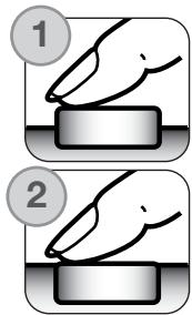
With the camera on a tripod, compose the picture as described in the basic recording section (p. 33). Focus lock (p. 34) or the Flex Focus Point (p. 48) can be used with off-center subjects. Press the shutter-release button partway down (1) to lock the exposure and focus. Press the shutter-release button all the way down (2) to begin the countdown. Because focus and exposure are determined when the shutter-release button is pressed, do not stand in front of the camera when setting up a self-timer image. Always confirm the focus with the focus signals before beginning the countdown (p. 35).
The self-timer lamp on the front of the camera and the audio signals indicate the countdown. The lamp will glow steadily just before the shutter fires. To stop the countdown, press the menu or function button or change the position of the flash (lift it or push it down). When using the ten-second self-timer, the drive mode is reset to single-frame advance after the exposure. The audio signal can be turned off in section 3 of the setup menu (p. 141).
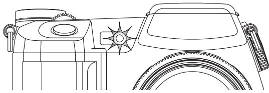
natural_image
Line drawing of a vehicle's front wheel, dashboard, and steering wheel (no text or symbols)Metering Modes
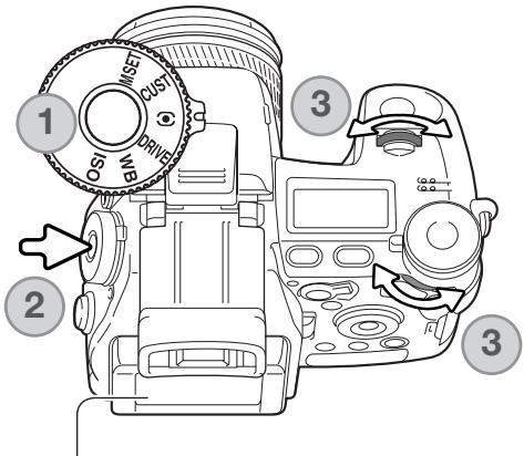
Metering mode indicators are displayed on the monitors only. To lock the exposure while pressing the shutter-release button partway down, the AE lock option in section 4 of the recording mode menu should be on. If the luminance levels of the scene are outside the metering range, the metering indicator turns red.
Turn the function dial to the metering mode position (1). Press the function button in the center of the dial (2). Turn the front or rear control dials to select the metering mode (3). Press the shutter-release button partway down or press the function button to set the mode.
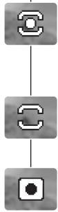
flowchart
graph TD
    A["Start"] --> B["Step 1"]
    B --> C["Step 2"]
Multi-segment - uses 300 segments to measure luminance and color. This data is combined with distance information to calculate the camera exposure. This advanced metering system will give accurate worry-free exposures in almost all situations.
Center weighted - a traditional metering method in film cameras. The system measures light values over the entire image area with emphasis given the central region.
Spot - uses a small area within the image to calculate the exposure. When this mode is selected, a small circle will appear in the middle of the live image indicating the measuring area. The spot allows precise exposure measurements of a particular object without being influenced by extremely bright or dark areas within the scene. When using spot metering with the Flex Focus Point (p. 48), the spot circle can move with the focus point. This function is selected in section 4 of the recording menu (p. 107).
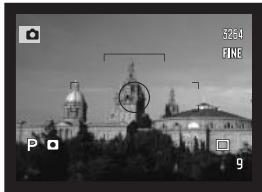
natural_image
Black-and-white cityscape photo featuring a prominent cathedral with domed architecture and a circular overlay of a target (no readable text or symbols)Spot metering display
White Balance
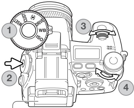
White balance is the camera's ability to make different types of lighting appear natural. Any changes are immediately visible on the monitors.
Turn the function dial to the white-balance (WB) mode position (1).
Press the function button in the center of the dial (2). Turn the front control dial to select the white-balance mode (3). Use the rear control dial (4) to shift the color balance of the preset modes or to select the custom white-balance register. Press the shutter-release button partway down or press the function button to set the mode.
AHB
Auto white balance - to automatically detect the type of light and adjust the white balance accordingly. When the built-in flash is used, the white balance is set for the color temperature of the flash. When set, no indicators appear on the data panel or monitors.
Daylight
Tungsten
Fluorescent
Cloudy
Shade
Flash
Preset white balance - to set the white balance to a specific light source. The rear control dial can be used adjust the white balance in seven levels: +3 to -3 (+4 to -2 for fluorescent). Except for fluorescent, the change of one unit is approximately equal to a 10 mired shift. When set, an indicator appears on the monitors and WB on the data panel. For information on light sources, see page 111.
Custom white balance - to apply custom white-balance settings. The rear control dial can be used to select one of three custom registers. When set, an indicator appears on the monitors and WB on the data panel. See page 71 on how to make custom white-balance calibrations.


Custom White-Balance Calibration
Custom-white-balance function allows the camera to be calibrated to a specific lighting condition. Three setting can be stored in the camera and used repeatedly. Custom white balance is especially useful with mixed-lighting conditions or when critical control over color is needed.
Select a white object and fill the center of the live image with it; the object does not need to be in focus. Press and hold the custom white-balance button to calibrate the camera; the measuring area is briefly displayed before the shutter releases.
On the register-selection screen use the control dials or left/right keys of the controller (1) to select the custom white-balance register in which to store the setting; any previous setting is replaced. Press the central button of the controller (2) to complete the operation. The menu button cancels the operation without saving the setting.
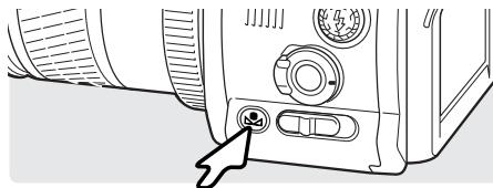
natural_image
Line drawing of a camera front panel with a cursor pointing to the button (no text or symbols)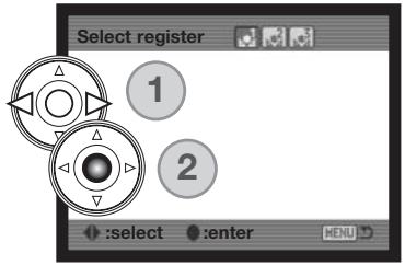
If an error occurs during calibration, a message will appear on the monitors. Press the controller to cancel the message and press the menu button to cancel the register-selection screen; the custom white-balance indicator will be yellow to indicate the error. Recalibrate using a suitable reference target. A calibration error may occur under extremely bright light sources, especially with flash units. Use a gray card as the calibration target to reduce the intensity of the illumination.
Shooting tips
When making the calibration, the color of the object used is critical. The object should be white. A colored object will cause the calibration to compensate for the object color rather than the color temperature of the ambient light. A blank piece of white paper is an ideal surface and can easily be carried in a camera bag.
Memory - Storing Camera Settings
Five sets of camera settings can be saved. This saves time under frequently repeating conditions by eliminating the need to set the camera. Except for functions like subject programs, data imprinting, voice memo, and instant playback, most recording-mode camera settings will be saved including the position of the Flex Focus Point, the display mode, and changes made with the function dial and digital effects control. Settings are displayed before being saved. Although the Digital Effects bracketing drive mode setting can be saved, the type of bracket, contrast, color saturation, or filter, must be reset with the Digital Effects Controller.
To save the current camera settings, turn the function dial to the M SET position and press the function button to open the register-selection screen; the current camera settings are displayed.
On the register-selection screen, use the control dials or left/right keys of the controller (1) to select the memory register in which to store the settings; any previous settings are replaced. Press the central button of the controller (2) to complete the operation. The menu button cancels the operation without saving the settings.
Camera settings cannot be deleted from memory by turning the camera off. They are erased with the reset function in section 3 of the setup menu.
Memory Recall
Camera settings saved with the function dial are recalled with the exposure-mode dial. Simply turn the exposure mode dial to the memory recall (MR) position (1); the register-selection screen will open.
natural_image
Two circular mechanical components with directional arrows and numbered circles (no text or symbols)On the register-selection screen use the control dials or left/right keys of the controller (2) to select the memory register in which the settings are stored; as the registers are selected the camera settings are displayed on the screen. Press the central button of the controller (3) to apply the settings to the camera. The menu button cancels the operation without recalling the settings.
To recall another set of settings in a different register, turn the exposure-mode dial to another position and then back to MR to open the memory-recall screen. Saved memory settings can also be assigned to the digital-subject-program positions on the exposure dial with section 4 of the recording menu. See page 106 for more information.
Camera Sensitivity - ISO
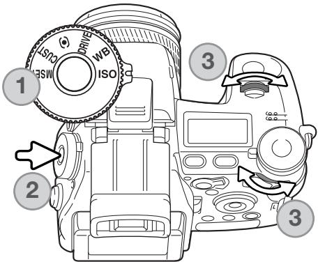
Five settings can be selected for camera sensitivity: Auto, 64, 100, 200, 400, and 800; the numerical values are based on an ISO equivalent. ISO is the standard used to indicate film sensitivity: the higher the number, the more sensitive the film.
Turn the function dial to the ISO position (1). Press the function button in the center of the dial (2). Turn the front or rear control dials to change the camera sensitivity (3). Press the shutter-release button partway down or press the function button to set the mode.
The auto setting automatically adjusts the camera sensitivity to the light conditions between ISO 64 and 200. When any other setting than auto is used, “ISO” will appear on the data panel, and “ISO” and the set value will be displayed on the monitors.
Photographers can select a specific sensitivity setting. Like grain in silver-halide film that increases with speed, noise increases with sensitivity in digital imaging; an ISO setting of 64 will have the least noise and 800 will have the most.
A change in ISO also affects the flash and shutter-speed range; the higher the ISO, the greater the range. See the next page for more on the flash range, and page 55 for the shutter-speed range.
As the ISO value doubles, the camera sensitivity doubles; changing the ISO between 100 and 200, 200 and 400, or 400 and 800 changes the camera sensitivity by one stop or 1 Ev (p. 111). A change between 100 and 800 changes the camera sensitivity by a factor of 8 or three stops. High ISO settings (400, 800) can allow the photographer to hand hold the camera in low-light conditions without the need of a flash.
Flash Range and Camera Sensitivity
For correct flash exposures, the subject must be within the flash range. The flash range can be extended by changing the camera sensitivity. When the camera sensitivity is set to auto, the ISO is set between ISO 64 and 200.
The flash range is measured from the CCD. Because of the optical system, the flash range is not the same at the lens' wide-angle position as it is at the telephoto position.
| ISO setting | Flash range (wide angle) | Flash range (telephoto) |
| 64 | 0.5m ~ 2.1m / 1.6 ft. ~ 6.9 ft. | 0.5m ~ 1.7m / 1.6 ft. ~ 5.6 ft. |
| 100 | 0.5m ~ 2.7m / 1.6 ft. ~ 8.8 ft. | 0.5m ~ 2.1m / 1.6 ft. ~ 6.9 ft. |
| 200 / AUTO | 0.5m ~ 3.8m / 1.6 ft. ~ 12.5 ft. | 0.5m ~ 3.0m / 1.6 ft. ~ 9.8 ft. |
| 400 | 0.5m ~ 5.4m / 1.6 ft. ~ 17.6 ft. | 0.5m ~ 4.2m / 1.6 ft. ~ 13.8 ft. |
| 800 | 0.5m ~ 7.6m / 1.6 ft. ~ 25 ft. | 0.5m ~ 6.0m / 1.6 ft. ~ 19.6 ft. |
Attaching an Accessory Flash Unit
To extend the versatility of the camera, an accessory flash unit (sold separately) can be used. Always remove the accessory flash when the camera is not in use, and replace the accessory-shoe cap to protect the contacts.
Slide the accessory-shoe cap off as shown. Mount the flash unit on the accessory shoe by sliding it forward until it stops.
System Accessories
The following flash units are compatible with this camera:
Maxxum/Program Flash 2500(D)
Maxxum/Program Flash 3600HS(D)
Maxxum/Program Flash 5600HS(D)
Macro Ring Flash 1200 with Macro Flash Controller
Macro Twin Flash 2400 with Macro Flash Controller
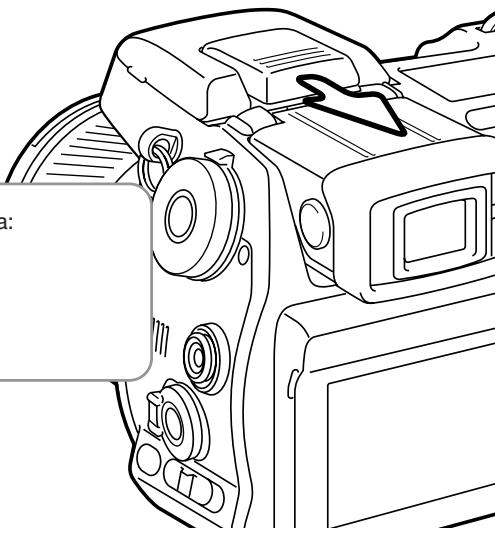
natural_image
Line drawing of a DSLR camera with no visible text or symbolsUsing the Flash Sync Terminal
The flash sync terminal allows a studio or location flash system to be connected to the camera with a standard PC cord. The terminal is compatible with both center positive (normal polarity) and center negative (positive polarity) flash units with a voltage of 400V or lower.
Unscrew the terminal cover. Securely connect the flash's PC cord to the flash sync terminal. Confirm the flash is off before connecting the cable to prevent it from firing. Always replace the cover when the terminal is not in use.
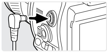
natural_image
Diagram of a car's seatbelt switch mechanism with no text or symbolsTo ensure correct exposures, use the manual exposure mode (p. 56). Set the shutter speed equal to or slower than the flash duration; refer to the flash unit's instruction manual. If the monitor image is too dark, change the manual-exposure option under monitor amplification to display priority in section 3 of the recording menu (p. 104).
If the built-in flash is raised when another flash unit is connected to the flash sync terminal, both flash units will fire. However, the camera's automatic flash control systems will not provide correct exposures. To use the built-in flash as a fill light, use manual flash control (p. 92).
The use of custom white balance is recommended (p. 71). When calibrating the camera, use the shutter speed and aperture settings require for the final exposure. A gray card may have to be used as the reference target with powerful flash units to reduce the intensity of the illumination. If custom white balance is not practical, use the preset daylight or flash setting; auto white balance is not recommended.
Depth-of-field Preview
The aperture controls depth of field; the area in front of the camera that appears in focus. The smaller the aperture, the greater the depth of field. Depth-of-field preview sets the aperture to the setting used in the exposure.
Turn the function dial to the custom position (1). Press and hold the function button to view the effect of the aperture setting on the live image. The shutter can be released during depth of field preview.
In Auto, P, and S exposure modes, the aperture value is automatically displayed. Except for the manual exposure mode, the exposure is not fixed and changes with the lighting conditions. The aperture can be changed during depth of field preview in A and M exposure modes; the live image may flash as the aperture is adjusted.
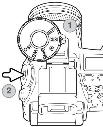
Camera Notes
The function assigned to the custom position of the function dial can be changed with the custom-setup option in section 2 of the setup menu (p. 136).
Digital Effects Control
The Digital Effects Controller can adjust image contrast, color, and saturation. Changes are instantly visible on the monitors before the image is captured.
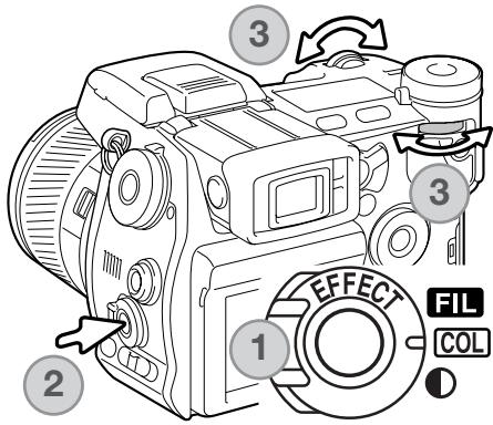
Turn the Digital Effect switch (1) to the image characteristic to be adjusted.
FIL Filter
COL Color-saturation
Contrast
Press the Digital Effects button (2) in the center of the switch; the setting screen is displayed. Turning the front or rear control dial (3) to make adjustments. Press the Digital Effects button again or press the shutter-release button partway down to set the adjustment. Also see camera notes on page 65.
Adjustments can be made repeatedly and in combination. Adjustments remain in effect until manually reset. When set to any value other than zero, an indicator and value will be displayed on the monitors as a warning.
Color-saturation Compensation

The color saturation of a scene can be adjusted within eleven levels ( ±5 ) with the Digital Effects Controller. Colors can be accented, positive value, or subdued, negative value.
Shooting tips
Unlike the display on a computer monitor, changes to contrast and color saturation can be difficult to judge on the monitor. To ensure the optimum level of contrast or color saturation, make a Digital Effect bracket (p. 62) of the scene.
Contrast Compensation

The contrast of a scene can be adjusted within eleven levels ( ±5 ) with the Digital Effects Controller. The contrast must be set before the image is captured. When changing the contrast setting, an indicator is displayed to show an increase (+) or decrease (−) in contrast. If contrast is set to any other value than zero, the indicator and value remain on the displays as a warning.
natural_image
Close-up of a single feather on a textured surface (no text or symbols visible)Contrast decreased

natural_image
Close-up of a single feather resting on a textured surface (no text or symbols visible)Contrast normal
natural_image
Close-up of a single feather on a textured surface (no text or symbols visible)Contrast increased
Filter

The overall color of a scene can be adjusted with the Digital Effect Controller. The Filter effects differ between the color mode in use, see the color examples on page 179. The filter must be set before the image is captured. When changing the setting, an icon and numeral will indicate the filter in effect. If the Filter is set to any other setting than zero, an indicator and value will remain on the displays as a warning.
When used with Natural Color, Vivid Color, or Adobe RGB, the Filter can be adjusted in eleven levels ( ±5 ). A positive adjustment acts like a warming filter. A negative adjustment makes the image cooler.
When used with the black-and-white color mode, the Filter can tone the neutral monochrome image in eleven steps. The Filter effect cycles from neutral to red, to green, to magenta, to blue, and returning to neutral. The zero position is neutral. Black and white filter settings have no effect on RAW images.
Recording Menu
In recording mode, press the menu button to activate the menu. The menu button also closes the menu after making settings. The four-way key of the controller is used to move the cursor in the menu. Pressing the central button of the controller will enter a setting.
Navigating the Recording Menu
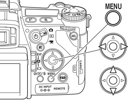
Activate the recording menu with the menu button. Tab 1 at the top of the menu will be highlighted.
Use the left/right keys of the controller to highlight the appropriate menu tab; the menus will change as the tabs are highlighted.
When the desired menu section is displayed, use the up/down key to scroll through the menu options. Highlight the option whose setting needs to be changed.

Press the right controller key to display the settings; the current setting is indicated by an arrow. To return to the menu options, press the left key.

Use the up/down key to highlight the new setting. If “Enter” is displayed, press the central button of the controller to open the next screen.

Press the central button of the controller to select the highlighted setting.
Once a setting has been selected, the cursor will return to the menu options and the new setting will be displayed. Changes can continue to be made. To return to the recording mode, press the menu button.
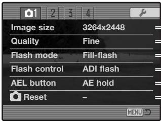
To set image resolution (p. 82).
To set file type and compression (p. 82).
To set the flash mode of the built-in flash (p. 86).
To set automatic or manual flash control (p. 92).
To customize the operation of the AEL button (p. 94).
To reset the recording-mode functions (p. 95).
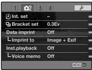
To set the interval drive mode parameters (p. 66)
To bracket with 0.3Ev or 0.5Ev steps (p. 96).
To imprint data on a recorded image (p. 98).
To imprint to the image or Exif data (p. 98).
To play back images after they are recorded (p. 100).
To attach audio to images after instant playback (p. 101).
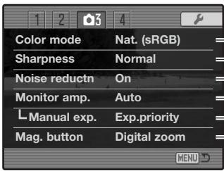
To select color or B&W images, and color space (p. 102).
To increase or decrease image sharpness (p. 97).
To apply noise reduction to long exposures (p. 103).
To activate automatic monitor amplification (p. 104).
To set M exposure mode monitor preferences (p. 104).
To set the digital zoom or Digital Flex Magnifier (p. 105).
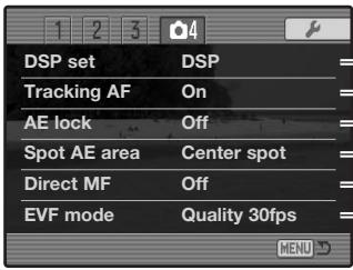
To use Digital Subject Programs for memory recall (p. 106).
To activate Subject Tracking AF (p. 106).
To activate AE lock with the shutter-release button (p. 106).
To select the spot metering area location with FFP(p. 107).
To activate Direct Manual Focus (p. 107).
To select the monitor frame rate (p. 108).
Image Size and Image Quality
Image size and quality are set in section 1 of the recording menu (p. 80). Changes are displayed on the LCD monitor and data panel.
| SIZE ■■■ | 3264 | 3264 X 2448 | RAWQUAL■■■ | RAW | RAW image |
| SIZE ■■■ | 3264 | 3264 X 2176 3:2 | RAWQUAL■■ | RAW+ | RAW & JPEG image |
| SIZE ■■ | 2560 | 2560 X 1920 | QUAL■■■■ | TIFF | TIFF image |
| SIZE ■■ | 2080 | 2080 X 1560 | QUAL■■■ | X.FIN | Extra fine JPEG image |
| SIZE ■ | 1600 | 1600 X 1200 | QUAL■■ | FINE | Fine JPEG image |
| SIZE | 640 | 640 X 480 | QUAL■ | STD. | Standard JPEG image |
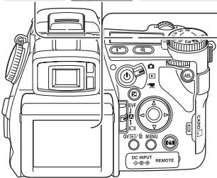
Image size affects the number of pixels in each image. The greater the image size, the larger the file size. Choose image size based on the final use of the image - smaller images are more suitable for web sites whereas larger sizes produce higher quality prints. The 3264 X 2176 option uses a 3:2 image ratio instead of the usual ratio of 4:3. When this is selected, the top and bottom of the monitor image is masked.
Image quality controls the file type and rate of compression. TIFF and RAW are high-quality image files. The extra fine, fine, and standard settings produce JPEG files at various rates of compression. The higher the image quality, the lower the rate of compression and the larger the file sizes. If economical use of the memory card is important, use the standard mode. The RAW & JPEG option creates two image files at one time, a 3264 X 2448 RAW file and a fine quality JPEG file with an image size selected with the menu. The image files are saved with the same file name, but with different extensions (p. 152). It can require more than 10 seconds to save RAW or TIFF files; the frame counter turns yellow and no images can be captured during this period.
Only full-size images can be taken with RAW image quality. RAW images require special processing before they can be used, refer to the DiMAGE Viewer software manual. Some camera functions cannot be used with the RAW image-quality setting. See page 84 for more information.
The number of images that can be stored on a memory card is determined by the size of the card and the file size of the images. One memory card can contain images with differing sizes and qualities. The actual file size is determined by the scene; some subjects can be compressed further than others.
Approximate file sizes.
| 3264x2448 | 3264x2176 | 2560x1920 | 2080x1560 | 1600x1200 | 640x480 | |
| RAW | 11,892KB | - | - | - | - | - |
| TIFF | 23,529KB | 20,928KB | 14,520KB | 9,626KB | 5,745KB | 1,020KB |
| Extra fine | 7,923KB | 7,056KB | 4,920KB | 3,289KB | 1,995KB | 420KB |
| Fine | 4,022KB | 3,588KB | 2,520KB | 1,704KB | 1,058KB | 270KB |
| Standard | 2,349KB | 2,102KB | 1,491KB | 1,025KB | 656KB | 240KB |
Approximate number of images that can be stored on a 128MB memory card.
| RAW | 10 | - | - | - | - | - |
| TIFF | 5 | 5 | 8 | 12 | 21 | 122 |
| Extra fine | 15 | 17 | 25 | 37 | 62 | 296 |
| Fine | 30 | 34 | 49 | 72 | 117 | 389 |
| Standard | 53 | 59 | 83 | 121 | 190 | 520 |
Camera Notes
The frame counter indicates the approximate number of images that can be stored on the memory card at the camera's image quality and size settings. If the settings are changed, the frame counter adjusts accordingly. Because the counter uses approximate file sizes, the actual image taken may not change the counter or may decrease it by more than one. When the frame counter displays zero, it indicates no more images at the image size and quality settings can be captured. Changing those settings may allow more images to be saved to the card.
About Raw Image Quality
In the RAW image-quality mode, the image size is set at full and cannot be changed. The image size will not be displayed on the monitors. The digital zoom, enlarged playback, data imprinting, and print functions cannot be used.
Unlike the other image-quality modes, RAW image data is unprocessed and requires image processing before it can be used. To view the RAW data, the DiMAGE Viewer software is required. This software can reconstruct the image and apply the same image processing controls as the camera. RAW data is saved as a 12-bit file; the DiMAGE Viewer software can convert this data into 24-bit or 48-bit TIFF files.
A RAW image is stored with a file header that contains white-balance information, changes made to contrast, saturation, and color with the Digital Effects Control, any image processing applied in a subject-program setting, and changes to sharpness. The changes in camera sensitivity are applied to the RAW data; ISO values can be manually set to control noise (p. 74).
The camera's image-processing controls apply the affect of the color modes to the live image on the monitors, but the stored data may not be influenced by the setting. The black and white color mode has no effect on the final image; a raw image taken in the black-and-white color mode can be restored to a color picture. However, black and white filter effects (p. 79) are not applied to a RAW image. The saturation difference between the Natural Color and Vivid Color modes is preserved in the RAW data, but the solarization color mode does not alter the image data. For more on color modes, see page 102.
Konica Minolta history
In the center of the Sakai plant in Japan is Okina bridge. In the 15th century, Sakai was a prosperous free city, and Okina bridge spanned the moat at one of the entrances into the walled town. For centuries, this bridge carried pilgrims on their way to two of Japan's sacred places: the mountain monastery of Koyasan and the great Shinto shrine, Kumano Taisha. The bridge in the courtyard dates from 1855, see photo on the next page. In 1968, Minolta offered to preserve the bridge when the city government announced they would fill in the moat for a planned highway. The bridge now spans a specially constructed goldfish pond. The writing on the stone bollard at the front of the bridge prohibits vehicles from crossing.
Notes on Image Size and Resolution
Image size changes the number of pixels in the image. When displayed at the same resolution, images appear to have the same amount of detail, but the dimensions of the image increases with the number of pixels; except for the 640 X 480 image, the other pictures are too large to be displayed on this page. When the images are enlarged to the same dimensions, the difference in the recorded image size affects the resolution of details.

natural_image
Pixelated grayscale image with no discernible text, symbols, or structured content.
natural_image
Close-up of a textured surface with granular patterns (no visible text or symbols)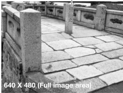
natural_image
Stone bridge structure with carved railings and a full image area label (640 X 480) at the bottom.

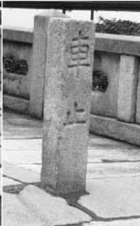

natural_image
Close-up of paved stone pavement with visible aggregate texture and cracks (no text or symbols)

natural_image
Close-up of cracked concrete pavement with a small rectangular object in the background (no text or symbols visible)


natural_image
Close-up of cracked concrete pavement with visible cracks and texture (no text or symbols)Flash Modes
The flash mode can be changed in section 1 of the recording menu (p. 80). For the flash to fire, the built-in unit must be manually lifted. The flash will fire in the selected mode regardless of the amount of ambient light. When the flash is used, the camera sensitivity is automatically set between ISO 100 and 200. This setting can be changed using the function dial (p. 74). The auto-white-balance setting will give priority to the flash's color temperature. If preset or custom white-balance settings are used, priority is given to the active setting's color temperature.
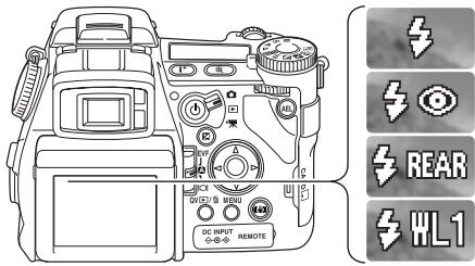
Fill-flash
Red-eye reduction
Rear flash sync
Wireless
Fill Flash
Fill-flash can be used as the main or supplementary light. In low-light conditions, the flash will act as the main source of illumination and overpower the ambient light. Under strong sunlight or in backlit situations, the fill-flash can reduce harsh shadows.
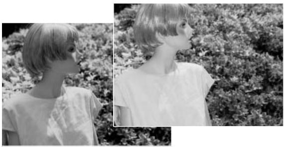
natural_image
Side-by-side black-and-white photo of a woman with short blonde hair, wearing a light-colored top, standing in front and back views of foliage (no text or symbols visible)Red-eye Reduction
Red-eye reduction is used when taking photographs of people or animals in low-light conditions. The red-eye effect is caused by light reflected from the retina of the eye. The camera will fire two pre-flashes before the main flash burst to contract the pupils of the subject's eyes.
Rear Flash Sync
Rear flash sync is used with long exposures to make trailing lights or blurring appear to follow rather than proceed the subject. The effect is not apparent if the shutter speed is too fast and stops the subject's motion.
When the shutter is released, a pre-flash will fire. This pre-flash does not expose the subject, but is used in the calculation of the flash exposure. The flash will fire again just before the shutter closes.
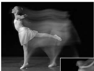
natural_image
Black-and-white photo of a dancer in mid-pose, captured mid-motion with motion blur effect (no text or symbols)
natural_image
Monochrome motion photo of a person in motion, possibly dancing or performing a dance or exercise (no text or symbols visible)Camera Notes
Slow shutter sync can be set in P and A exposure modes. This flash mode controls the shutter and aperture to balance the ambient and flash illumination. When photographing a subject outside at night, the ambient-light exposure will be balanced to bring out the details in the background with the flash exposure for the subject. Because shutter speeds can be longer than usual, the use of a tripod is recommended.
- Set the camera to the P or A exposure mode (p. 50).
- Frame the subject on the monitors.
- Press and hold the AE lock button to lock the exposure.
- Press the shutter-release button partway down to lock the focus. Compose the image on the monitors.
- Press the shutter-release button all the way down to take the picture.
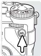
The operation of the AE lock button can be changed in section 1 of the recording menu.
System Accessories
The Close-up Diffuser CD-1000 is used directly on the camera with the built-in flash to provide soft lighting for close-up photography. Contact your local Konica Minolta dealer for more information.
Wireless / Remote Flash

natural_image
Black-and-white photo of a woman seated at a desk with a lamp and curtains in the background (no visible text or symbols)On-camera flash
Wireless/Remote flash

natural_image
Black-and-white photo of a woman seated at a desk with arms crossed, next to a person in the background (no visible text or symbols)Wireless/Remote flash allows the camera to control an off-camera Program/Maxxum 5600HS(D) or 3600HS(D) flash unit without the need of a cable. Single or multiple flash units can be placed around the subject to create different lighting effects.
The camera's built-in flash fires to control the off-camera flash units rather than to illuminate the subject. See your local camera dealer about Minolta lighting accessories.
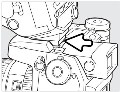
natural_image
Technical line drawing of a mechanical assembly with no visible text or symbolsSlide the cap off the accessory shoe (p. 75).
Slide the Program/Maxxum 5600HS(D) or 3600HS(D) flash on the accessory shoe until the safety lock engages.
Turn on the camera and flash unit.
Set the camera to the wireless flash mode in section 1 of the recording menu (p. 80). This will simultaneously set the flash to the wireless mode and set the camera to the flash's wireless channel.
Press and hold the mounting-foot-release button (1) to disengage the safety catch to remove the flash unit from the camera.
natural_image
Illustration of three camera components: a DSLR camera, a potted flower, and a compact DSLR camera (no text or symbols)Position the camera and flash around the subject. See the following page for the camera-to-subject and flash-to-subject ranges. Make sure no objects come between the camera and flash unit.

Raise the built-in flash on the camera. The wireless flash indicator (WL) will be displayed in the top left corner of the live image. The number next to it indicates the channel in use. The flash signal will turn white when the flash is charged.
When the 5600HS(D) or 3600HS(D) flash is charged, the AF illuminator on the front of the unit will blink (2). Take a picture as described in the basic recording section on page 33.
The flash units can be test fired by pressing the AEL button on the camera. If the flash does not fire, change the camera, flash, or subject position. The slow-shutter-sync function can be used in P and A exposure modes (p. 87).
natural_image
Illustration of a black-and-white photo flash unit with a starburst light on the side (no text or symbols)Wireless/Remote Camera and Flash Ranges
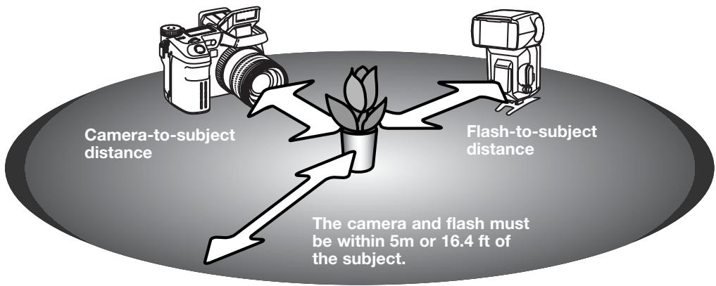
Minimum camera-to-subject distance
| Aperture | Camera sensitivity setting (ISO) | ||||
| 64 | 100 | 200 / AUTO | 400 | 800 | |
| f/2.8 | 1.1 m / 3.6 ft | 1.4 m / 4.6 ft | 2.0 m / 6.6 ft | 2.8 m / 9.2 ft | 3.9 m / 12.8 ft |
| f/4.0 | 0.8 m / 2.6 ft | 1.0 m / 3.2 ft | 1.4 m / 4.6 ft | 2.0 m / 6.6 ft | 2.8 m / 9.2 ft |
| f/5.6 | 0.6 m / 2.0 ft | 0.7 m / 2.3 ft | 1.0 m / 3.2 ft | 1.4 m / 4.6 ft | 2.0 m / 6.6 ft |
| f/8.0 | 0.4 m / 1.3 ft | 0.5 m / 1.6 ft | 0.7 m / 2.3 ft | 1.0 m / 3.2 ft | 1.4 m / 4.6 ft |
| Minimum flash-to-subject distance | |||||
| f/2.8 | 0.8 m / 2.6 ft | 1.0 m / 3.2 ft | 1.4 m / 4.6 ft | 2.0 m / 6.6 ft | 2.8 m / 9.2 ft |
| f/4.0 | 0.6 m^3 / 2.0 ft^3 | 0.7 m / 2.3 ft | 1.0 m / 3.2 ft | 1.4 m / 4.6 ft | 2.0 m / 6.6 ft |
| f/5.6 | 0.4 m^4 / 1.3 ft^4 | 0.5 m^1 / 1.6 ft^1 | 0.7 m / 2.3 ft | 1.0 m / 3.2 ft | 1.4 m / 4.6 ft |
| f/8.0 | 0.3 m^5 / 0.9 ft^3 | 0.4 m^2 / 1.3 ft^2 | 0.5 m1 / 1.6 ft^1 | 0.7 m / 2.3 ft | 1.0 m / 3.2 ft |
1 Maximum flash-to-subject distance: 3600HS(D) - 3.6 m / 11.8 ft.
2 Maximum flash-to-subject distance: 3600HS(D) - 2.5 m / 8.2 ft. 5600HS(D) - 4.0 m / 13.1 ft.
3 Maximum flash-to-subject distance: 3600HS(D) - 4.0 m / 13.1 ft.
4 Maximum flash-to-subject distance: 3600HS(D) - 2.8 m / 9.2 ft. 5600HS(D) - 4.2 m / 13.8 ft.
5 Maximum flash-to-subject distance: 3600HS(D) - 2.0 m / 6.6 ft. 5600HS(D) - 3.0 m / 9.8 ft.
Notes on Wireless/Remote Flash
Wireless/Remote flash performs best under subdued light or interior lighting. Under bright light sources, the flash may not be able to detect the control signals from the camera's built-in flash.
The wireless/remote system has four channels so that multiple lighting systems can be used in the same area without affecting each other. Once the camera and flash are separated, the wireless channel can be changed. Refer to the flash's instruction manual on how the set the wireless channel. The flash and the camera must be set to the same channel.
When not using off-camera flash units, always turn off the wireless flash mode in section 1 of the recording menu, or inaccurate flash exposures will result. The 5600HS(D) and 3600HS(D) flash units can be reset simultaneously with the camera. Simply mount the flash unit in the accessory shoe and change the wireless flash mode setting on the menu to another flash mode.
This camera does not have a preset flash sync speed. In program (P) or aperture-priority (A) exposure mode, the shutter speed will not fall below the camera-shake limit unless the slow-sync function is activated (p. 87). When using shutter-priority (S) or manual (M) exposure mode, any shutter speed can be used for the exposure.
The flash can synchronize with the camera at any shutter speed, the 5600HS(D) and 3600HS(D) high-speed sync function is unnecessary. When using flash, the shutter speed should be set to the flash duration of flash unit to prevent underexposure. A maximum shutter speed of 1/250s is recommended when using a compatible Minolta flash unit. The Wireless/Remote Flash Controller is not compatible with this camera.
Flash Control
ADI, pre-flash TTL, and manual flash controls are available. Flash control is changed in section 1 of the recording menu (p. 80).
ADI (Advanced Distance Integration) flash metering - combines distance information from the auto-focusing system with information from a pre-flash exposure. Unlike conventional TTL flash metering, ADI is not influenced by the reflectance of the subject or background ensuring optimum flash exposures.
Pre-flash TTL - calculates flash exposure with a pre-flash only. This mode must be used when using close-up filters or filters that reduce the amount of light entering the camera such as neutral density filters. Pre-flash TTL must be used when a diffuser is attached to the built-in flash or an external flash unit.
The camera will automatically switch from ADI metering to pre-flash TTL when a low-contrast subject is preventing the autofocus system from focusing. If the autofocus system cannot lock on the subject, use manual focus; the ADI metering will remain in effect.
Manual flash control - fires the flash at full power, 1/2, 1/4, 1/8, or 1/16 power. Because no pre-flash is used, it can be used to fire slave flash units. Manual flash cannot be used with red-eye reduction or wireless.
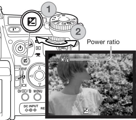
Select the manual option from flash control in section 1 of the recording menu. With the built-in flash raised, press the exposure compensation button (1). Use the rear control dial (2) to select the manual flash power ratio; the front control dial compensates the ambient exposure.
Press the shutter-release button partway down or press the exposure-compensation button to complete the operation. The power ratio and the manual flash indicator are displayed on the monitors when the flash is raised.
The chart lists approximate guide numbers for manual flash calculations. The following equations are useful in determining the guide number (GN), aperture (fn), or flash-to-subject distance required for exposures.
| Guide no. (for distance in meters / feet) | |||||
| Manual flash | Camera sensitivity (ISO) | ||||
| 64 | 100 | 200 | 400 | 800 | |
| 1/1 (Full) | 6.3 / 21 | 8 / 26 | 11 / 36 | 16 / 52 | 22 / 72 |
| 1/2 | 4.5 / 15 | 5.6 / 18 | 8 / 26 | 11 / 36 | 16 / 52 |
| 1/4 | 3.2 / 10 | 4 / 13 | 5.6 / 18 | 8 / 26 | 11 / 36 |
| 1/8 | 2.2 / 7.2 | 2.8 / 9.2 | 4 / 13 | 5.6 / 18 | 8 / 26 |
| M1/16 | 1.6 / 5.2 | 2 / 6.6 | 2.8 / 9.2 | 4 / 13 | 5.6 / 18 |
$$ \frac {\mathrm{GN}}{f \mathrm{n.}} = \text { dist. } $$
$$ G N = f n. X \text { dist. } $$
$$ \frac {\text { GN }}{\text { dist. }} = f \text { n }. $$
Flash Notes
Maxxum/Program Flash 2500(D), 3600HS(D), 5600HS(D), Macro Ring Flash 1200, and Macro Twin Flash 2400 are compatible with this camera. ADI flash metering works with the three Maxxum/Program flashes attached to the accessory shoe. See the flash manual on how to set ADI metering. The use of other flash units is not recommended.
With the Maxxum/Program Flash 5600HS(D) and 3600HS(D), the flash-metering mode will automatically switch to pre-flash TTL when the bounce-flash or wireless/remote function is used, or the flashes are connected to the camera with an off-camera cable. Pre-flash TTL automatically activates when using the macro flash units. When using bounce flash with the Maxxum/Program Flash 2500(D), set TTL with the metering mode switch on the flash unit or pre-flash TTL on the recording menu on the camera.
When using the Maxxum/Program flash units, if the flash illumination is uneven at the camera's wide-angle lens position, attach the wide-angle adapter to the flash units. With the 3600HS(D), also change the flash metering mode to pre-flash TTL. When the auto-zoom function is used with the Maxxum/Program 3600HS(D) and 5600HS(D) flash units, the flash's zoom setting will be wider than the lens setting.
When using the Macro Ring Flash 1200 or Macro Twin Flash 2400 in macro mode (p. 49), light fall off toward the edges of the frame may be noticeable at the wide-angle macro lens position.
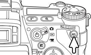
When the AEL button is pressed and held, the exposure is locked. The exposure remains locked after an image has been captured until the AEL button has been released (hold setting) or pressed again (toggle setting). How the button operates can be changed in section 1 of the recording menu (p. 80).
| Menu option | |
| AE hold | The default setting. Press and hold the AEL button to lock the exposure. The exposure remains locked until the AEL button is released. |
| AE toggle | Press and release the AEL button to lock the exposure. To cancel the exposure lock, press the AEL button again. |
| AE hold | Exposure is determined with the spot metering area. Press and hold the AEL button to lock the exposure; the spot circle is displayed. The exposure remains locked until the AEL button is released. |
| AE toggle | Exposure is determined with the spot metering area. Press and release the AEL button to lock the exposure; the spot circle is displayed. To cancel the exposure lock, press the AEL button again. |
These menu options do not affect the operation of the manual shift function (p. 56).
Recording Mode Reset
The recording mode functions can be reset in section 1 of the recording menu (p. 80). When selected, a confirmation screen will appear; choosing "Yes" resets the following functions and settings, "No" cancels the operation.
| Exposure compensation | 0.0 | p. 59 |
| Flash compensation | 0.0 | p. 59 |
| Drive mode | Single-frame advance | p. 61 |
| Anti-shake | On | p. 37 |
| White balance | Auto | p. 70 |
| White-balance shift | 0 | p. 70 |
| Metering mode | Multi-segment | p. 69 |
| Contrast compensation | 0 | p. 79 |
| Color-saturation compensation | 0 | p. 78 |
| Filter | 0 | p. 79 |
| Focus area | Wide focus frames | p. 33 |
| Flash mode | Fill flash or red-eye reduction1 | p. 86 |
| Flash control | ADI | p. 92 |
| Sharpness | Normal | p. 97 |
- The flash mode is reset to whichever of the two modes was last set.
Button shortcuts can be used to reset the recording mode (p. 132). The confirmation screen will not appear in the shortcut operation.
Interval Setup
The parameters for the interval drive mode (p. 66) are set in section 2 of the recording menu (p. 80).
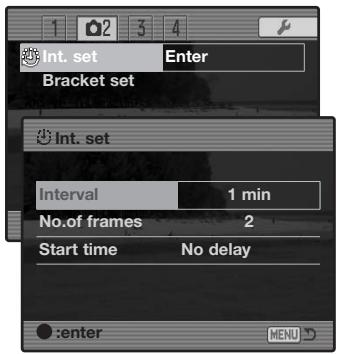

Select “Enter” in the interval-set option in section 2 of the recording menu. Press the center of the controller to open the setup screen.


On the setup screen, use the up/down controller keys to highlight the parameter to be changed and then press the right controller key. Use the up/down keys to change the parameter. Use the left controller key to return to the parameters. Continue until the parameters are set.

Press the center of the controller to complete the operation. The menu button closes the screen and cancels any changes.
Bracketing Setup
When making an exposure bracket (p. 62), the exposure difference between frames can be set to 0.3EV or 0.5Ev. This is set in section 2 of the recording menu (p. 80).
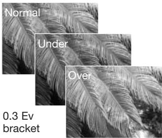
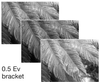
natural_image
Close-up of fern fronds with visible venation, labeled '0.5 Ev bracket' (no other text or symbols)Sharpness
The sharpness of the image can be altered. This must be set before the image is recorded. Sharpness is set in section 3 of the recording menu (p. 80). If any setting other than normal is selected, the sharpness indicator is displayed on the monitors.
| Menu options | ||
| Hard (+) |  | Increases the sharpness of the image, accentuating details. |
| Normal |  | No filter applied. |
| Soft (−) | [5x7W] | Softens the details of the image. |
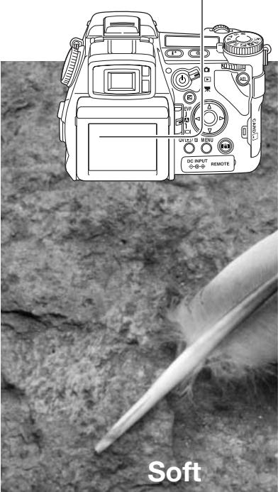
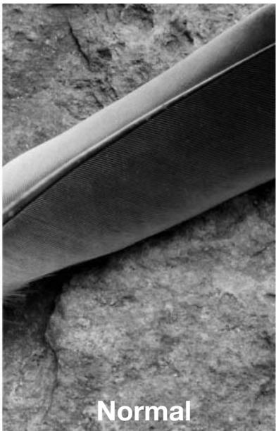

Data Imprinting
Data can be printed on a still image and saved to the file's Exif data. The function must be activated before the image is taken. Once activated, data will continue to be imprinted until the function is reset; a yellow bar is displayed behind the frame counter on the monitors to indicate the function is active. Data imprinting is selected in section 2 of the recording menu (p. 80). Data imprinting cannot be used with TIFF, RAW, and RAW & JPEG image quality. Only one imprinting format can be used with each image.
| Menu option | |
| Off | Data imprinting function disabled. |
| YYYY/MM/DD | Prints the year, month, and day the image was taken. The date format can be changed with Date/Time set option in section 2 of the setup menu (p. 30). |
| MM/DD/hr:min | Prints the date and time the image was taken. |
| Text | To imprint alphanumeric characters. When this option is selected, the electronic keyboard opens (p. 99). |
| Text + ID# | To imprint text with a serial number. As each successive image is captured, the ID number will increase by one. When this option is selected, the electronic keyboard opens (p. 99). The serial number is reset every time this option is selected. |
The data can be imprinted in the lower right corner of the image when viewed horizontally as well as to the file's Exif data, or to the Exif data only. The Exif data can be seen with the DiMAGE Viewer software. The imprinting location is selected with the imprint-to option in section 2 of the menu.
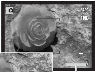
natural_image
Close-up grayscale image of a rose flower on textured ground, with no visible text or symbolsImprinting indicator
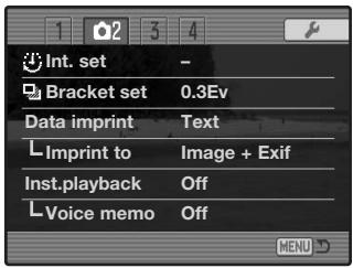
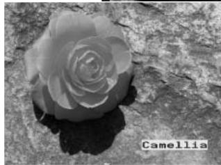
natural_image
Black and white close-up of a rose on a textured rock surface, labeled 'Camellia' in the corner (no other text or symbols)Electronic Keyboard
The electronic keyboard is used to enter text for imprinting data or for naming new folders. The keyboard automatically appears when text needs to be entered.
To enter text, simply use the four-way keys of the controller to highlight the desired character and then press the central button of the controller to enter it. Highlight the case key and press the center of the controller to switch between upper case, lower case, and Japanese; the change is immediately displayed on the keyboard.
To enter the text and complete the operation, highlight the enter key and press the controller. To cancel the operation, press the menu button.
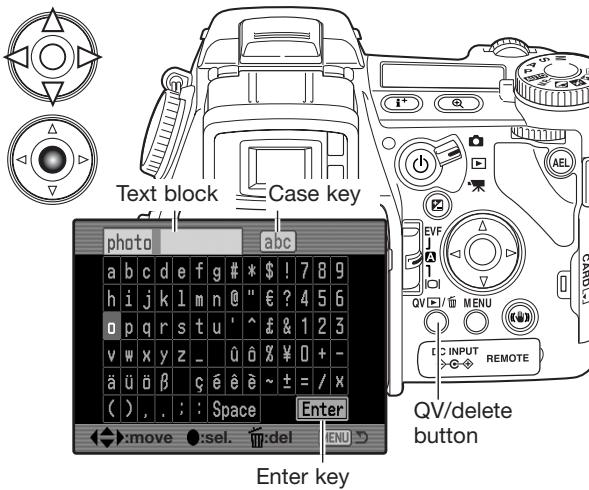
To delete text, move the cursor into the text block at the top of the screen. Use the cursor to highlight the character to be deleted. Press the QV/delete button to delete the character.
To replace a character, highlight the character in the text block then highlight the new character on the keyboard. Press the center button of the controller to replace the character.
Camera Notes
While the Japanese character set can be imprinted directly on the image, the Exif data may not be correctly displayed with the DiMAGE Viewer because of the limits of the computer's operating system.
Instant Playback
After an image is captured, it can be displayed on the monitors for two or ten seconds before being saved. When using the continuous-advance or continuous-advance bracketing drive mode, an index display is used. Instant-playback is activated and the length of the playback period is set in section 2 of the recording menu (P.80).
natural_image
Black-and-white photo of a dense cluster of white flowers with no visible text or symbols
If the central button of the controller is pressed during the instant playback period, the displayed image(s) are saved immediately and the playback canceled.

Pressing the display-information button switches between displaying the image with and without the guidance bar.

To delete an image during the instant playback, press the QV/delete button. A confirmation screen will appear.

Use the left/right keys of the controller to highlight "YES." "NO" will cancel the operation.

Press the central button of the controller to delete the image. When a continuous or bracketed series of images is captured, the entire series will be erased.
Voice Memo
Voice memo allows up to fifteen seconds of audio to be recorded with a still image. The function is activated in section 2 of the recording menu (p. 80) and is used in unison with instant playback. When the function is active, the microphone indicator is displayed on the monitors. Voice memo must be set before taking a picture. It will remain in effect until reset.
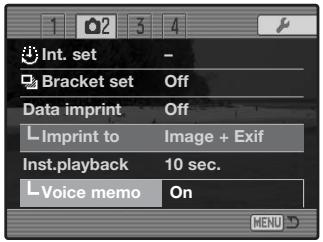
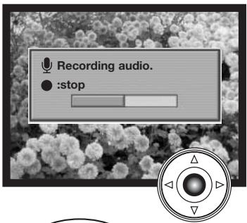
After the instant playback period, a screen will appear indicating the audio recording has started. A status bar will display the amount of recorded time. The recording will stop when the fifteen second recording period has ended or by pressing the center button of the controller.
A voice memo is attached to the last image of a continuous-advance or continuous-advance bracketing series (p. 61). The voice memo can be played back in Quick View and the playback mode (p. 115).
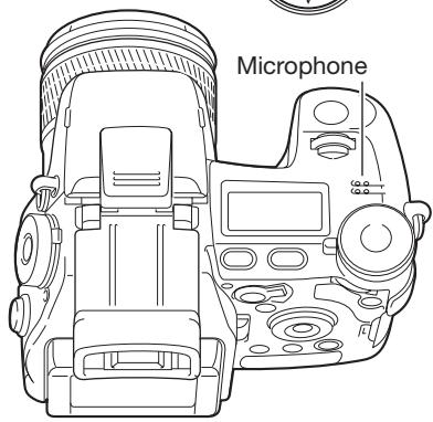
Recording Tips
When making audio recordings, be careful not to touch or cover the microphone. The quality of the recording is proportional to the subject to microphone distance. For best results, hold the camera approximately 20cm (8in) from your mouth.
During instant playback, if the central button of the controller is pressed, the image is saved and the voice-memo recording starts. If the shutter-release button is pressed partway down, the image is saved and the voice-memo recording is canceled.
Color Mode
The color mode controls whether a still image is color or black and white. This must be set before the image is recorded. The color mode is set in section 2 of the recording menu (p. 80). The live image on the monitors will reflect the selected color mode. The color mode has no effect on image file size. See the color examples on page 103.
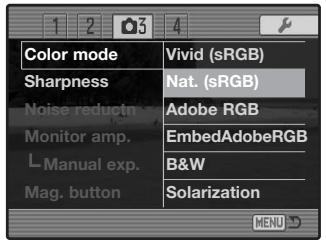
flowchart
graph TD
    A[" "] --> B["YIVID"]
    B --> C["Adobe"]
    C --> D["Adobe"]
    D --> E["BW"]
    E --> F["SOL"]
Natural Color - reproduces the colors in the scene faithfully. This mode uses no monitor indicator when active. Employs the sRGB color space.
Vivid Color - increases the saturation of the colors in the scene. The increased saturation affects the RAW image data. Employs the sRGB color space.
Adobe RGB - like Natural Color, this color mode reproduces the colors in the scene faithfully, but uses the extended gamut of the Adobe RGB color space.
Embedded Adobe RGB - the same as Adobe RGB, except that the color space is embedded in the image file.
Black & White - produces monochrome images. Images can be toned using the Filter setting on the Digital Effects Controller (p. 78).
Solarization - produces a partial reversal of tones in the image. Exposure compensation function can be used to accentuate the solarization effect (p. 59). The Digital Effects Controller cannot be used. This color mode does not affect RAW images. For more on RAW image quality and color mode, see page 84.
natural_image
Close-up photo of three peaches on a blue plate with camera and image editing icons (no text or symbols on the objects themselves)Natural Color and Adobe RGB - reproduces the colors in the scene faithfully.
natural_image
Close-up photo of three peaches on a blue plate with camera and image editing icons (no readable text or symbols)Vivid Color - increases the saturation of the colors in the scene.
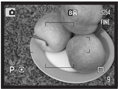
natural_image
Black-and-white photo of three fruits on a plate with camera and image editing icons (no readable text or symbols)Black & White - produces monochrome images.

Solarization - produces a partial reversal of tones and colors in the image.
About Adobe RGB
Adobe RGB has a larger color gamut than the more common sRGB. The size of the gamut limits the colors that can be reproduced; the larger the gamut, the more colors. If the image will be printed out with a high-quality printer, the use of the Adobe RGB color mode is recommended over the sRGB color modes of Natural and Vivid Color.
Color matching must be used when opening Adobe-RGB image files. The use of embedded Adobe RGB is recommended. When using the DiMAGE Viewer, the color matching function must be active and the color space set to Original Color Space (Adobe RGB) in the color preferences window. See color matching in the advanced setup section in the DiMAGE Viewer manual. DiMAGE Viewer version 2.2 or later is required to open Adobe RGB images taken with this camera.
Noise Reduction
This function reduces the affect of dark noise caused by long exposures. Noise reduction is only applied to exposures of one second or longer. Processing is applied to each image after it is captured. The monitor remains blank during processing for a maximum of 30 seconds. Noise reduction uses dark-frame subtraction.
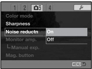
Monitor Amplification
The monitor amplification options control the display of the live image. Monitor amplification has two settings:
Auto - in low-light conditions when the camera-sensitivity gain has reached its limit, the automatic monitor-amplification function will intensify the monitor image. Although the live image turns black and white, this does not affect the color mode in use.
When the automatic monitor amplification activates, the Flex Digital Magnifier (p. 105) cannot be used. If the real-time histogram (p. 45) is used, it will reflect the amplified image and not the final values of the exposure.
Normal - the monitor image is not amplified in low light.
When using the manual (M) exposure mode (p. 56), two other options are available:
Exposure priority - the live image reflects the set exposure. Automatic monitor amplification is disabled.
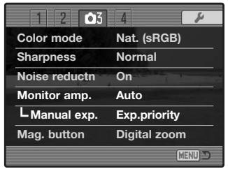
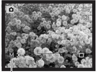
natural_image
Microscopic view of a dense cluster of spherical particles with no visible text or symbolsDisplay-priority indicator
Display priority - the live images is displayed regardless of the exposure settings. This allows the image to be composed on the monitor when using a flash as the main light source. When selected, the manual exposure mode indicator turns red on the monitor.
Magnification Button
The function assigned to the magnification button can be changed between the digital zoom (p. 47) and the Flex Digital Magnifier in section 3 of the recording menu (p. 80). The Flex Digital Magnifier can only be used during manual focus. Button shortcuts can be used to switch between the digital zoom and Flex Digital Magnifier (p. 132).
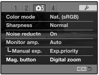
Flex Digital Magnifier
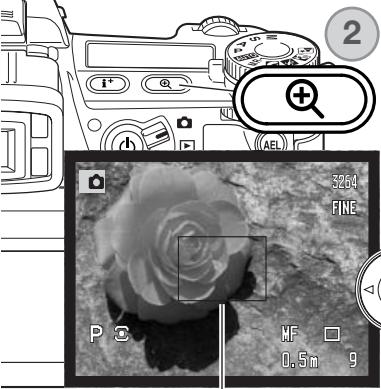
The Flex Digital Magnifier is a focusing aid for manual focus (p. 46). The live image can be magnified by X3.3. It is activated with the recording menu, see above. This function is disabled in the other focusing modes.

natural_image
Two circular diagrams with directional arrows and a numbered circle (1), no text or symbols present.Initially, the 3.3X magnification area is displayed. This can be moved in the live image with the four-way keys of the controller (1). Pressing the center button of the controller returns the area to the middle of the image. Press the magnification button (2) to enlarge the image.
Magnification area
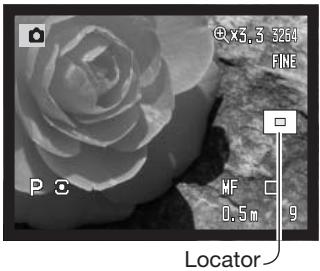
When enlarged, the degree of magnification is displayed in the top right corner of the monitor. The controller can be used to scroll and center the image area. Pressing the magnification button again cancels the magnified image.
The locator shows which portion of the image is displayed. When the shutter-release button is pressed partway down, the entire image area is displayed.
DSP (Digital Subject Program) Setup
The memory registers used for camera settings can be assigned to the Digital Subject Program positions on the exposure-mode dial. This is set in section 4 of the recording menu (p. 80). Two options are available:
DSP - the Digital Subject Programs are active on the exposure-mode dial.
Memory recall - the memory registers are assigned to the Digital Subject Program positions as indicated in the illustration.
For more about Digital Subject Programs, see page 58. To save camera settings turn to page 72.
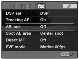
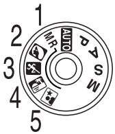
Tracking AF
Subject Tracking AF used in the continuous AF focus mode (p. 46) can be turned off in section 4 of the recording menu (p. 80). When off, the position of the focus area can still be changed with the four-way keys of the controller.
AE Lock
AE (autoexposure) lock can be turned off and on in section 4 of the recording menu (p. 80). When AE lock is on, the exposure is locked when the shutter-release button is pressed partway down; the shutter speed and aperture displays turn black to confirm the exposure lock. When AE lock is off, the exposure continues to change with the lighting conditions when the shutter-release button is pressed partway down. This has no affect on the operation of the AEL button (p. 50). When using single-shot AF with multi-segment metering, AE lock is always active regardless of the menu setting.
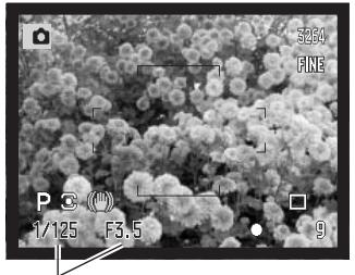
natural_image
Microscopic view of a granular material surface with no visible text or symbolsExposure locked
Spot AE Area
When using spot metering (p. 69) with the Flex Focus Point (p. 48), the position of the spot metering area can be specified at the center of the live image or linked to the Flex Focus Point; the spot moves after the position of the FFP is set. This is set in section 4 of the recording menu (p. 80).
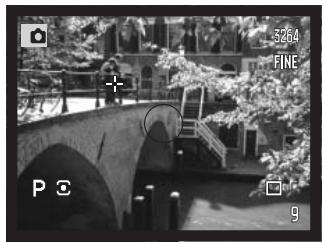
natural_image
Black-and-white photo of a stone arch bridge over a water body with trees and buildings in the background (no visible text or symbols)Center spot
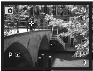
natural_image
Black-and-white photo of a stone arch bridge over water with trees and buildings in the background (no visible text or symbols)With Flex Focus Point
Direct Manual Focus
Direct manual focus allows manual adjustments to be made after the AF system has locked onto the subject. Direct manual focus is activated in section 4 of the recording menu (p. 80). Direct manual focus is canceled when continuous AF or manual focus (p. 46) is in use.
As described in the basic recording operation section (p. 33), press the shutter-release button partway down to lock the focus (1); the focus signal will turn white. "DMF" will be displayed next to the drive-mode indicator.
While holding the shutter-release button partway down, the camera can be manually focused with the focusing ring (2). Always use the monitor image to confirm focus. The approximate focusing distance is displayed next to the frame counter. If active, the Flex Digital Magnifier (p. 105) can be used.
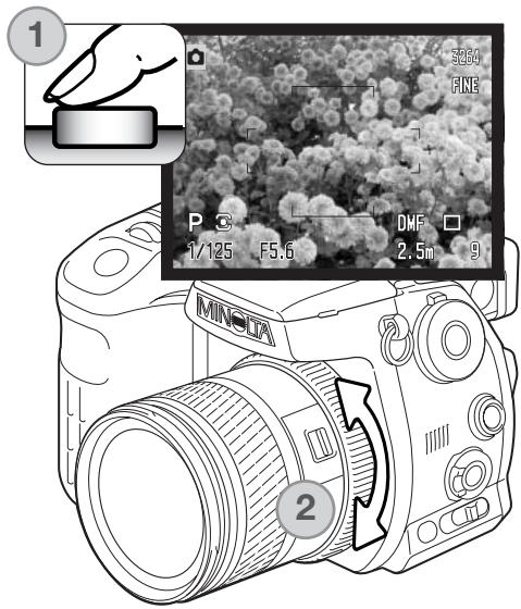
EVF Mode
The frame rate of the EVF can be specified; the monitor is not affected. This is set in section 4 of the recording menu (p. 80). Two options are available:
Quality 30fps - high-resolution VGA (640x480) viewfinder image at 30 frames per second.
Motion 60fps - smooth 60 frames-per-second viewfinder image for use with moving subjects. Half VGA (640x240) resolution. If full-time AF (p. 143) or movie recording is used, the frame rate is set to 30fps.
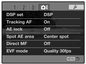
Minolta History
On February 20th, 1962, John Glenn became the first American to orbit the Earth. On board his Friendship 7 spacecraft was a Minolta Hi-matic camera to record that historic event. The 4 hour, 55 minute, and 23 second flight orbited the Earth three times at an average speed of 28,000 kph (17,500 mph).
Mr. Glenn visited our Sakai camera factory in Japan on May 24th, 1963 to plant a palm tree to celebrate the occasion. The palm tree is still in the courtyard of the factory and stands over eight meters tall (26ft).
The camera? It was not lost. It is on display at the Smithsonian Institution's National Air and Space Museum in Washington D.C. This and other objects from John Glenn's Friendship 7 Mercury flight can be found in galley 210, “Apollo to the Moon.”
A short Guide to Photography
Photography can be a rewarding pursuit. It is a broad and disciplined field that can take years to master. But the pleasure in making photographs and the joy of capturing a magical moment cannot be compared. The guide is an introduction to some basic photographic principles.
The lens aperture controls not only exposure, but also depth of field; the area between the closest object in focus and the furthest object in focus. The larger the aperture value, the greater the depth of field and the longer the shutter speed needed to make the exposure. The smaller the aperture value, the shallower the depth of field and the faster the shutter speed needed to make the exposure. Usually landscape photographs use a large depth of field (large aperture value) to keep the foreground and background in focus, and portraits use a shallow depth of field (small aperture value) to separate the subject from the background.
Depth of field also changes with focal length. The smaller the focal length, the greater the depth of field; the longer the focal length, the shallower the depth of field.
The shutter controls not only exposure, but also the ability to stop motion. Fast shutter speeds are used in sport photography to stop action. Slow shutter speeds can be used to show the flow of motion such as water cascading over a waterfall. The use of a tripod is recommended with slow shutter speeds.
The change in aperture and shutter speed is not apparent in the live image. For critical work, take a test photograph and view the result in Quick View (p. 40).

natural_image
Black-and-white photo of a smiling child on a beach holding a net, no text or symbols visible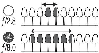
natural_image
Black and white photo of a cascading waterfall over rocky terrain (no text or symbols visible)About Exposure and Flash Compensation
Sometimes the camera's exposure meter is deceived by certain conditions. Exposure compensation can be used in these situations. For example, a very bright scene, such as a snowy landscape or a white sandy beach, can appear too dark in the captured image. Before taking the picture, adjusting the exposure by +1 or +2 EV will result in an image with normal tonal values.
natural_image
Black and white photo of scattered white maple leaves on a leafy background (no text or symbols)Calculated camera exposure
natural_image
Black and white photo of scattered maple leaves on a dark background (no text or symbols)-1.0Ev
natural_image
Black and white close-up of scattered maple leaves on a dark, textured surface (no text or symbols visible)-2.0Ev
In the example above, the dark water caused the camera to overexpose the image making it bright and washed-out. By compensating the exposure, detail is brought out in the leaves, and the stones and water appear richer.
When using fill-flash to reduce harsh shadows caused by bright illumination or direct sunlight, flash compensation can change the ratio between the highlights and shadows. The fill-flash will affect the darkness of the shadows without affecting the area illuminated by the main light source. By decreasing the flash output with a negative Ev setting, the shadows receive less light and are harder, but subtle details in the shadows that would not appear without the flash are apparent. Increasing the flash output by using a positive Ev setting softens and nearly eliminate shadows.

natural_image
Black-and-white portrait of a woman with short hair, wearing a white top, against a blurred floral background (no text or symbols visible)Positive compensation

natural_image
Side profile of a person with short hair wearing a white top, set against a blurred background of shrubs (no text or symbols visible)No compensation

natural_image
Side profile of a person with short blonde hair wearing a white top, set against a blurred floral background (no text or symbols visible)Negative compensation

natural_image
Black-and-white photo of a person with short blonde hair wearing a top, standing outdoors near floral background (no text or symbols visible)No flash
What is an EV?
Ev stands for exposure value. A change of one Ev adjusts the exposure calculated by the camera by a factor of two.
| +2.0 Ev | 4X as much light |
| +1.0 Ev | 2X as much light |
| 0.0 Ev | Calculated exposure |
| -1.0 Ev | 1/2 as much light |
| -2.0 Ev | 1/4 as much light |
Light Sources and Color
The human eye adapts itself extremely well under different conditions. The paper of this manual you are reading looks white regardless of the type of lighting. Photographic systems are much less flexible. As the light source changes, so does the overall color of a scene - fluorescent office ceiling lights create a green cast to pictures, regular household tungsten light bulbs make everything red. Like your eyes, the camera's white-balance controls adjust for different lighting to make natural looking pictures.
The most common source of light, our sun, changes color depending on the time of day and the atmospheric conditions. The sun is of course very warm near the horizon and very blue at noon. The daylight preset white-balance setting is for beautiful sunny days. When the weather is overcast, the color is cooler. When the main light source is skylight, light from the blue sky rather than the direct light of the sun, the resulting color is very blue. The shade preset white-balance is designed for this condition.
Artificial lighting is more consistent but will show variations. Tungsten lamps become warmer as their wattage decreases. And fluorescent lamps come in classifications that define their color. The preset white balance settings can be adjusted with the rear control dial (p. 70) to match the change in these light sources.
Some artificial lighting has a discontinuous spectrum that creates very unnatural color in a photograph. White balance cannot correct high-energy vapor lighting: sodium-vapor (yellow highway lights), or mercury vapor. For portraits under these lighting conditions, the flash can be used to overpower the ambient light. With landscapes containing these types of lights, set the white balance to the preset daylight setting.
Movie Menu
In movie mode, press the menu button to activate the menu. The menu button also closes the menu after making settings. The four-way key of the controller is used to move the cursor in the menu. Pressing the central button of the controller will enter a setting.
Navigating the Movie Menu
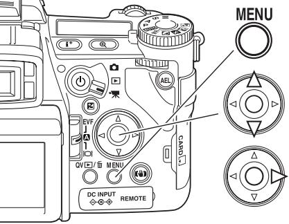
Activate the recording menu with the menu button. Tab 1 at the top of the menu will be highlighted.
Use the up/down key to scroll through the menu options. Highlight the option whose setting needs to be changed.
Press the right controller key to display the settings; the current setting is indicated by an arrow. To return to the menu options, press the left key.

Use the up/down key to highlight the new setting. If “Enter” is displayed, press the central button of the controller to continue.

Press the central button of the controller to select the highlighted setting.
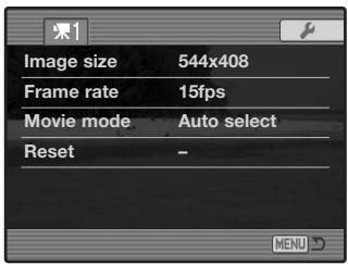
Once a setting has been selected, the cursor will return to the menu options and the new setting will be displayed. Changes can continue to be made. To return to the movie mode, press the menu button.
Image Size and Frame Rate
Movies can be recorded at two sizes: 544x408 and 320x240. The larger the image size, the higher the image quality and the larger the file sizes. Image size is set in the movie menu.
Movies can be recorded at two frame rates: 15 fps and 30 fps. The higher the frame rate, the smoother the moving image and the larger the file sizes. Frame rate is set in the movie menu. The computer environment may affect the playback of 544x408 30fps movies.
If image size or frame rate is changed, the frame counter displays the approximate number of seconds that can be recorded at that setting on the installed memory card. The total time that can be stored on a memory card is determined by the size of the card and the recording rate. The actual file size is determined by the scene; some subjects can be compressed further than others.
| Approximate recording rate | ||
| 544x408 | 320x240 | |
| 30fps | 945KB/s | 578KB/s |
| 15fps | 558KB/s | 297KB/s |
| Approximate capacity of a 128MB memory card | ||
| 30fps | 2 min. 02 sec. | 3 min. 26 sec. |
| 15fps | 3 min. 24 sec. | 6 min. 42 sec. |
Movie Mode
The movie mode option selects the type of movie recorded. Three options are available on the movie menu:
Standard movie - to record a color movie under normal lighting conditions.
Night Movie - to record under low light levels. Night Movies are black and white. While Night Movies can be recorded under normal conditions, bright outdoor lighting may be beyond the exposure control range.
Auto select - automatically switch between standard and Night Movie modes depending on the lighting conditions. When recording, the mode is fixed.
Movie Reset
This menu function resets the movie mode. When selected, a confirmation screen will appear; choosing “Yes” resets the following functions and settings, “No” cancels the operation.
| Exposure compensation | 0.0 | p. 59 |
| Contrast compensation | 0 | p. 79 |
| Color-saturation compensation | 0 | p. 78 |
| Filter | 0 | p. 79 |
| White balance | Auto | p. 70 |
| Image size | 544x408 | p. 113 |
| Frame rate | 15fps | p. 113 |
| Movie mode | Auto select | p. 113 |
| Anti-shake | On | p. 37 |
Button shortcuts can be used to reset the recording mode (p. 132). The confirmation screen will not appear in the shortcut operation.
Notes on Movie Recording
The list below indicates which functions can be set in the movie mode:
| Available recording functions | |
| Exposure compensation (p. 59) | Anti-shake (p. 37) |
| Contrast compensation (p. 79) | Display information button (p. 45) |
| Color-saturation compensation (p. 78) | Manual focus (p. 46) |
| Filter (disabled with Night Movies)(p. 79) | Macro mode (p. 49) |
White balance (p. 70)
Custom white-balance calibrations can only be made in the recording mode. Once made, the setting are available for movie recording.
Advanced Playback
This section covers how to playback voice memos as well as the playback mode's menu functions. The menu navigation section covers basic menu operation. It is followed by detailed descriptions of the menu settings.
Playing Back Voice Memos
Voice memos can be played back in Quick View and the playback mode. See page 101 on how to record voice memos.
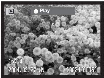
natural_image
Microscopic view of a dense cluster of spherical particles under scanning (no text or symbols visible)
Voice memos are indicated by the voice-memo indicator displayed at the bottom of the monitor image.

Press the central button of the controller to start the audio playback.
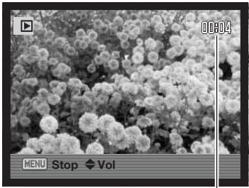
natural_image
Black-and-white photo of a dense cluster of white flowers with no visible text or symbols
During playback, use the up/down keys of the controller to adjust the volume.

Press the menu button to cancel audio playback.
Playback time
Navigating the Playback Menu
In playback mode, press the menu button to activate the menu. The menu button also closes the menu after making settings. The four-way key of the controller is used to move the cursor in the menu. Pressing the central button of the controller will enter a setting.
Activate the playback menu with the menu button. Tab 1 at the top of the menu will be highlighted.
Use the left/right keys of the controller to highlight the appropriate menu tab; the menus will change as the tabs are highlighted.

When the desired menu section is displayed, use the up/down key to scroll through the menu options. Highlight the option whose setting needs to be changed.

Press the right controller key to display the settings; the current setting is indicated by an arrow. To return to the menu options, press the left key.

Use the up/down key to highlight the new setting. If “Enter” is displayed, press the central button of the controller to open the next screen.

Press the central button of the controller to select the highlighted setting.
Once a setting has been selected, the cursor will return to the menu options and the new setting will be displayed. Changes can continue to be made. To return to the playback mode, press the menu button.
To delete images on the memory card (p. 119).
To format the memory card (p. 120).
To select the folder to view in playback mode (p. 120).
To protect images from deletion (p. 121).
To copy images from one memory card to another (p. 122).
To specify the index playback format (p. 121).
To play back images automatically (p. 124)
To select the images for the Slide Show (p. 124).
To specify how long each image is played back (p. 124)
To repeat the Slide Show presentation automatically (p. 124).
To select images for DPOF printing (p. 126).
To print the date of capture with each print (p. 127)
To create an index print with the DPOF order (p. 127)
To cancel DPOF print orders on the memory card (p. 127).
Frame-selection Screen
When a marked-frames setting is chosen on a menu, the frame selection screen will appear. This screen allows multiple files to be selected. The index format of the screen can be changed in section 1 of the playback menu (p. 121).
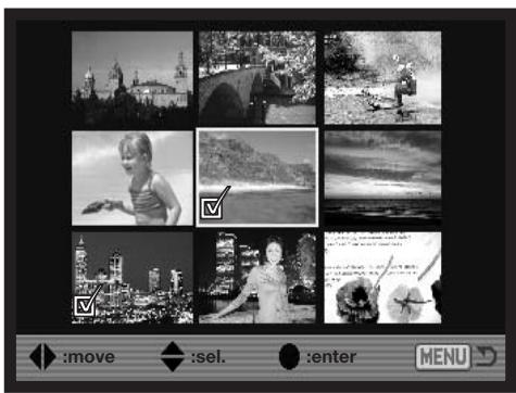

The left/right keys of the controller move the yellow border to select the image.

The up key of the controller selects the frame; when selected, an indicator appears next to the thumbnail. The down key deselects the image removing the indicator.
As images are selected, indicators appear next to the frame:
| The file is selected for deletion. | |
| The file is locked or selected to be locked. | |
| The file is selected for the slide show or to be copied to another memory card. | |
| The image is selected for printing. The number next to the indicator shows the number of copies requested. |


Delete

Deleting permanently erases the image. Once deleted, an image cannot be recovered. Care should be taken when using the delete function.
Single, multiple, or all images in a folder can be deleted with the playback menu. Before an image is deleted, a confirmation screen will appear; choosing "Yes" will execute the operation, "No" will cancel the operation. To delete images in other folders, the folder must first be selected with the view-folder option in section 1 of the playback menu (p. 116) or the select-folder option in section 2 of the setup menu (p. 137). The delete option has three settings:
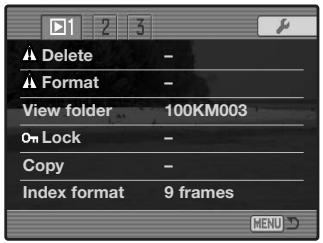
This frame - The image displayed or highlighted in playback mode will be deleted.
All frames - All unlocked images in the selected folder will be deleted.
Marked frames - To delete multiple images. When this setting is chosen, the frame-selection screen will be displayed. Use the left/right keys of the controller to highlight the first image to be deleted. Pressing the up key will mark the thumbnail with the delete indicator. To deselect an image for deletion, highlight it with the yellow border and press the down key; the delete indicator will disappear. Continue until all the images to be deleted are marked. Press the controller to continue (the confirmation screen will appear), or press the menu button to cancel the operation and return to the playback menu. On the confirmation screen, highlighting and entering “Yes” will delete the marked images.
The delete function will only erase unlocked images. If an image is locked, it must be unlocked before it can be deleted.
Format

When a memory card is formatted, all data on the card is erased.
The formatting function is used to erase all data on a memory card. Before formatting a card, copy the data to a computer or storage device. Locking files will not protect them from being deleted when the card is formatted. Always format the memory card using the camera; never use a computer to format a card.
When the format option is selected and entered, a confirmation screen will appear. Choosing “Yes” will format the card, choosing “No” will cancel the formatting operation. never remove the card while it is being formatted. A screen will appear to indicate the card has been formatted; press the central button of the controller to return to the playback menu.
Although it is recommended to format a CompactFlash card with the camera, a card can be formatted with a computer. The card must be formatted on a Windows system using a FAT or FAT32 file system.
View Folder
Recorded images are stored in folders on the memory card. To view or edit these images, the folder they are contained in can be selected temporarily with the view-folder option in section 1 of the playback menu (p. 116). The view-folder option is reset to the folder selected in the select-folder option in section 2 of the setup menu (p. 137) each time the camera is turned off or switched to the recording or movie modes.
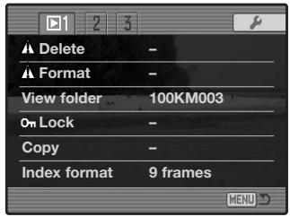
For more on memory card organization, see page 152. Folders can be created and selected in section 2 of the setup menu (p. 129).
Lock
Single, multiple, or all images in a folder can be locked. A locked image cannot be deleted by either the playback menu functions or the QV/delete button. Important images should be locked. To lock images in other folders, the folder must first be selected with the view-folder option in section 1 of the playback menu (p. 116) or the select-folder option in section 2 of the setup menu (p. 137). The lock option has four settings:
This frame - The image displayed or highlighted in playback mode will be locked.
All frames - All images in the folder will be locked.
Marked frames - To lock or unlock multiple images. When this setting is chosen, the frame-selection screen (p. 118) will be displayed. Use the left/right keys of the controller to highlight the image to be locked. Pressing the up key will mark the thumbnail with the lock indicator. To unlock an image, highlight it with the yellow border and press the down key; the lock indicator will disappear. Continue until all the images are marked. Press the controller to lock the marked frames, or press the menu button to cancel the operation and return to the playback menu.
Unlock frames - All images in the folder will be unlocked. A confirmation screen appears.
Locking an image will protect it from a delete function. However, the formatting function will erase all files on a memory card whether locked or not.
Index Playback Format
The index format option allows the index playback to be displayed with four or nine images. This affects all index displays.
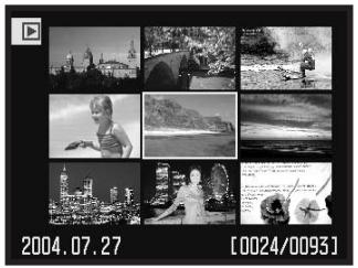
natural_image
Grid of black-and-white photos showing urban scenes and a person in a wheelchair, with date and time labels (2004.07.27, 2004/0093) at the bottom.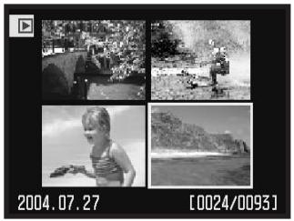
natural_image
Four-panel black-and-white photo collage showing outdoor scenes, a child playing, and a beach with hills in the background (no text or symbols)Copy
Image files can be copied from one memory card to another. Up to 29MB of data can be transferred. Every time the copy function is used, a new folder is automatically created for the image(s).
This frame - To copy the image currently displayed.
Marked frames - To copy single or multiple images. When selected, the frame-selection screen (p.118) will appear; highlight the images to be copied with the yellow border and then press the up key of the controller to mark it with the check indicator. To deselect an image, highlight the selected thumbnail and press the down key; the check indicator will disappear. Continue until all the images are marked. Press the central button of the controller to continue, or press the menu button to cancel the operation and return to the playback menu.
When the controller is pressed, a screen with four messages will be displayed; the messages are highlighted as the copying procedure is executed. If too many images have been selected, a warning will appear and the copy routine will be canceled. Divide the number of images into two or three batches.
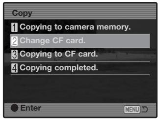
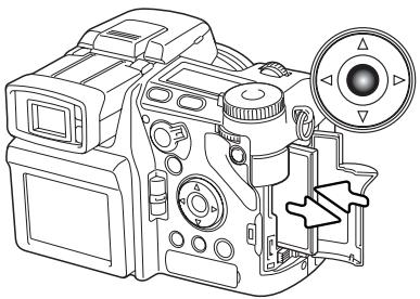
natural_image
Technical line drawing of a DSLR camera with control panel and adjustment knob (no text or symbols)When the change-CF-card message is highlighted, remove the camera's memory card and insert the card to which the image is to be copied. If the card has insufficient space, the card-full warning is briefly displayed; insert a different card or press the menu button to cancel the routine. Press the central button of the controller to continue.
Wait until the copy-completed message is highlighted. A new screen will appear to indicate the name of the new folder containing the copied images; press the central button of the controller to return to the playback menu.
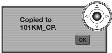
If the images were copied to a new card, the no-images message will be displayed when viewed on the camera. Select the copy folder with the view-folder option in section 1 of the playback menu (p. 116).
Konica Minolta History
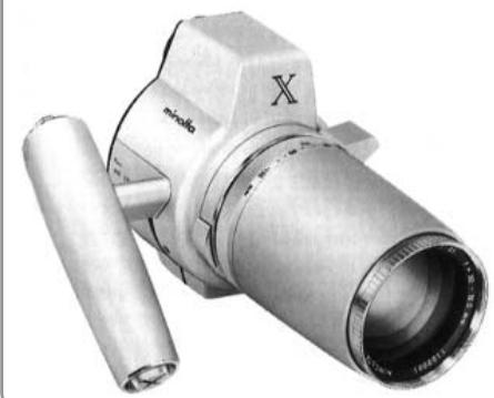
natural_image
Close-up of a metallic mechanical device with a cylindrical shaft and hexagonal top (no visible text or symbols)Innovation and creativity has always been a driving force behind our products. The Electro-zoom X was purely an exercise in camera design. It was unveiled at Photokina in Germany in 1966.
The Electro-zoom X was an electronically controlled aperture-priority mechanical SLR with a built-in 30 - 120mm f/3.5 zoom lens giving twenty 12 X 17mm images on a roll of 16mm film. The shutter-release button and battery chamber are located in the grip. Only a few prototypes were built making it one of our rarest cameras.
Slide Show
Section 2 of the playback menu controls the slide-show function. This function automatically displays all still images in a folder in order.
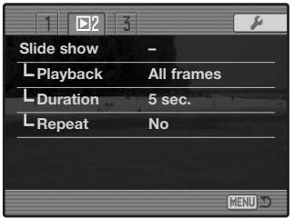
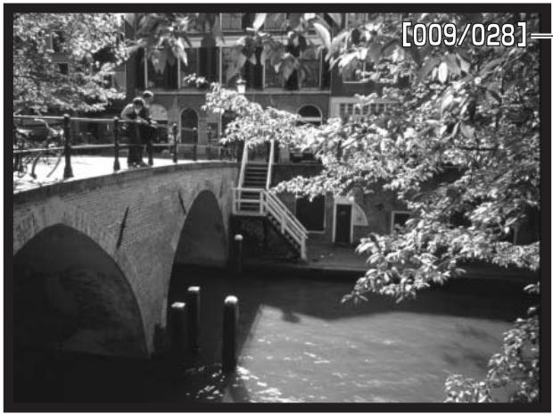
natural_image
Black-and-white photo of a stone arch bridge over a river with people walking on it, surrounded by trees and a building in the background (no visible text or symbols)- Number of image displayed / total number of images in the presentation.

Press the central button of the controller to pause and restart the presentation.

Use the left/right keys of the controller to advance to the next image or return to the previous one.


To cancel the presentation, press the menu button or the down key of the controller.
| Menu options | Settings | |
| Slide show | Enter | To start the slide-show presentation. Pressing the central button of the controller will pause the presentation. During the slide show, press the menu button or the down key of the controller to stop the presentation and return to the playback-mode menu. |
| All frames | To select all the images in the folder to be displayed in the slide-show presentation. | |
| Playback | Marked Frames | To select specific images in the folder to be displayed in the slide-show presentation. When this setting is chosen, the frame-selection screen (p. 118) will be displayed. Use the left/right keys of the controller to highlight the image to be included in the presentation. Pressing the up key will mark the image with a check indicator. To deselect a marked image, highlight it with the yellow border and press the down key; the check indicator will disappear. Continue until all the images have been edited. Press the controller to set the marked frames, or press the menu button to cancel the operation and return to the playback menu. |
| Duration | 1 - 60s. | To select the period each image will be displayed during the slide show. |
| Repeat | Yes / No | Selecting “Yes” will cause the slide show to repeat until it is canceled using the menu button or the down key of the controller. “No” will end the slide show presentation and return to the playback-mode menu when all the images have been displayed once. |
About DPOF
This camera is supported by DPOF ^™ version 1.1. The DPOF (Digital Print Order Format) allows direct printing of still images from digital cameras. After the DPOF file is created, the memory card is simply taken to a photofinishing service or inserted into the memory -card slot of DPOF compatible printers. When a DPOF file is created, a misc. folder is automatically made on the memory card to store it (p. 152). DPOF print files cannot be made for RAW images or images with embedded color profiles (p. 102).
DPOF Setup
The print menu option is used to set an order for standard prints from images in a specific folder. Single, multiple, or all images can be printed. If a memory card has multiple folders, a printing file must be created for each folder. Folders are selected with the view-folder option in section 1 of the playback menu (p. 116) or the select-folder option in section 2 of the setup menu (p. 137).
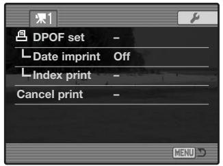
This-frame - To create a DPOF file for the image displayed or highlighted in playback mode.
All-frames - To create a DPOF file for all images in the folder specified in section 1 of the playback menu.
Marked frames - To choose a group of images to be printed or when the number of copies for each image varies. When selected, the frame-selection screen will appear (p. 118). Use the left/right keys of the controller to highlight an image to be printed. Pressing the up key will mark the image with the printer indicator. The number next to the indicator indicates the number of copies of that image will be printed. Pressing the up key will increase the number of copies, pressing the down key will decrease the number. A maximum of nine copies can be ordered. To deselect an image for printing, press the down key until the the number of copies reaches zero and the printer indicator disappears. Continue until all the images to be printed are marked. Press the controller to create the DPOF file, or press the menu button to cancel the operation and return to the playback menu.
When the this-frame or all-frames setting is chosen, a screen will appear requesting the number of copies of each image; a maximum of nine copies can be ordered. Use the up/down keys of the controller to set the number of copies desired. If the all-frames setting was used to create a print order, any additional images saved afterwards in the folder will not be included in the order.
DPOF files created with another cameras will be canceled.
Date Imprint
To print the date of capture with each image with a compatible DPOF printer, turn the menu option on. To cancel date imprint, simply turn the option off. How the date is printed varies with the printer.
Index Print
To create an index print of all the images in the folder, select the Yes option. To cancel an index print, simply change the setting to "No." If an index-print order is created, any additional images saved afterwards in the folder will not be included in the index print. The number of images printed per sheet differs between printers. The information printed with the thumbnails can vary.
Cancel Print
After the pictures have been printed, the DPOF file will still remain on the memory card and must be canceled manually. The cancel-print option deletes the DPOF files. When the setting is selected, a confirmation screen will appear; choosing and entering “Yes” will execute the operation and cancel the print and index-print order.
All frames C - To cancel all printing files on the memory card.
All frames F - To cancel the printing file in the folder.
Viewing Images on a Television
It is possible to view camera images on your television. The camera has a video-out terminal which can be used to connect the camera to a television using the supplied AV cable. The camera is compatible with the NTSC and PAL standards. The video-output setting can be checked and set in section 1 of the setup menu (p. 129).
- Turn off the television and the camera.
- Insert the single plug of the AV cable into the camera's AV-out terminal.
- Plug the other end of the AV cable into the video and audio input terminal on the television. The yellow plug is for the video output, and the white plug is for the monaural audio output.
- Turn the television on.
- Change the television to the video channel.
- Turn on the camera and set the mode switch to the playback position. The camera's monitors will not activate when the camera is attached to a television. The playback-mode display will be visible on the television screen.
- View images as described in the playback section. Use the television controls to adjust the volume of the audio playback. Because of the broadcast standard used to display television images, image quality and resolution will appear lower than when displayed on a computer monitor.
Setup Menu
The setup menu controls camera operations. The menu navigation section covers basic menu operation. It is followed by detailed descriptions of the menu settings.
Opening the Setup Menu
The setup menu can be opened two ways.
To access the menu directly, hold down the function button (1) and press the menu button (2) to open the setup menu.
Setup tab


The setup menu can be accessed from the recording, movie, or playback menus.
Use the left/right keys of the controller to highlight the setup tab. Press the central button of the controller to open the setup menu.
Navigating the Setup Menu
See page 129 on how to open the setup menu. The four-way key of the controller is used to move the cursor in the menu. Pressing the central button of the controller will enter a setting.
Use the left/right keys of the controller to highlight the appropriate menu tab; the menus will change as the tabs are highlighted.
When the desired menu section is displayed, use the up/down key to scroll through the menu options. Highlight the option whose setting needs to be changed.

Press the right controller key to display the settings; the current setting is indicated by an arrow. To return to the menu options, press the left key.

Use the up/down key to highlight the new setting. If “Enter” is displayed, press the central button of the controller to open the next screen.

Press the central button of the controller to select the highlighted setting.
Once a setting has been selected, the new setting will be displayed. To return to the mode set with the mode switch, press the menu button.
To set monitor brightness (p. 132).
To display button shortcut information (p. 132).
To specify camera operation with a computer (p. 135).
To set the automatic display function (p. 135).
To switch video output between NTSC and PAL (p. 135).
To set the menu language (p. 135).
To allocate a custom function to the function dial (p. 136)
To activate file number memory (p. 136).
To select the folder name format (p. 137).
To select the destination folder for recorded images (p. 137).
To create a new folder (p. 138).
To set the camera's clock and calendar (p. 138).
To reset camera functions (p. 139).
To change or turn off audio signals (p. 141).
To change or turn off focus signals (p. 141).
To change or turn off the shutter sound effect (p. 142).
To adjust or turn off the volume of camera signals (p. 142).
To set the auto power save period (p. 142).
To specify when Anti-shake is applied (p. 143).
To activate Full-time AF (p. 143).
To activate the grip sensor (p. 143).
To customize control dial operation (p. 144).
To customize manual exposure operation (p. 145).
To change the confirmation screen's default setting (p. 145).
To specify the lens accessory in use (p. 145).
This tab may not be active. A firmware update is provided with the lens accessory.
LCD Brightness
The brightness of the EVF and LCD monitor is set independently of each other. Select the display to adjust using section 1 of the setup menu; the corresponding monitor activates automatically and the brightness screen is displayed.

Brightness is controlled in eleven levels. Use the left/right controller keys to adjust the brightness The monitor will adjust accordingly. Press the central button of the controller to set the level and complete the operation. Press the menu button to close the screen without applying any changes.


Shortcut Help
The shortcut help shows button commands to open the LCD brightness screen, change the focusing screens, switch between the digital zoom and Flex Digital Magnifier, open the setup menu, or reset the camera. To close the help screen, press the menu button.
The following shortcuts can be used:
Press and hold the display information button to open the LCD brightness screen.
natural_image
Front view of a DSLR camera with control panel and buttons (no text or symbols visible)
m161
To display a grid or scale over the display formats, press and hold the function button (1) and press the display-information button (2) to cycle through the options: grid, scale, and off. For more on the displays modes, see page 45.
When using manual focus, a shortcut allows switching between the digital zoom (p. 47) and the Flex Digital Magnifier (p. 105). The shortcut is different depending on which function is selected in the mag. button option in section 3 of the recording menu.
Digital zoom selected on the menu
If the digital zoom is not activated, press and hold the function button (1) then press the magnification button (2) to activate the Flex Digital Magnifier. The image can be scrolled using the four-way keys of the controller when magnified. If the digital zoom is active, the display switches between the digital zoom and the Flex Digital Magnifier.
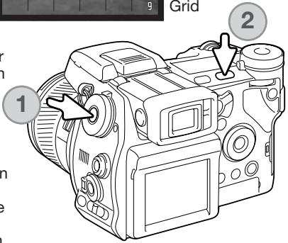
Flex Digital Magnifier selected on the menu
Without the live image magnified, press and hold the function button (1) then press the magnification button (2) to activate the digital zoom. Press the magnification button to switch between the digital zoom and the Flex Digital Magnifier.
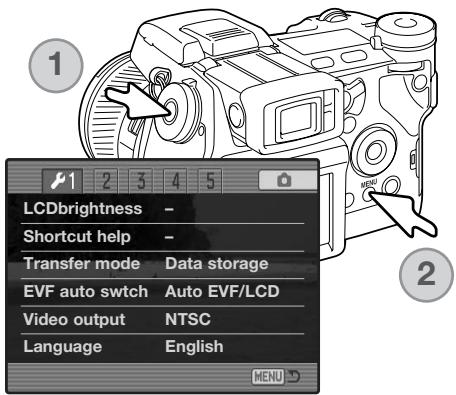
Hold down the function button (1) and press the menu button (2) to open the setup menu.
Hold down the function button (1) and press the QV/delete button (2) to reset the camera. This shortcut only resets the recording mode or movie mode depending on the position of the mode switch. Refer to page 95 to see which functions reset in the recording mode, and page 114 for the movie mode.
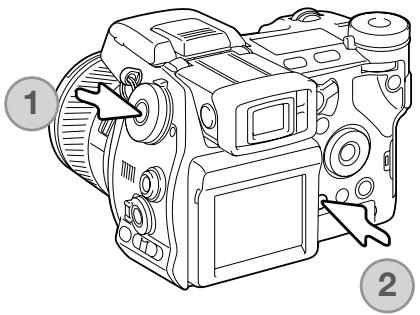
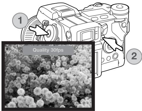
Hold down the function button (1) and press the exposure-compensation button (2) to switch the EVF mode between Quality 30fps and Motion 60fps. Each time this shortcut is used, the active EVF mode is briefly displayed at the top of the monitor. If on, the Motion 60fps EVF mode is canceled when full-time AF (p. 143) is activated.
Transfer Mode
The data-transfer mode must be specified depending on whether the camera is used to transfer data to a computer, print images with a PictBridge compatible printer, or record images with the optional DiMAGE Capture software. Select the appropriate option:
Data storage - to transfer data between the camera and a computer. This option must be selected when moving image files to a computer or when using the DiMAGE Viewer software.
PTP - to print images with a PictBridge compatible printer.
Comp. control - to record images from a computer using the optional DiMAGE Capture software. A firmware update is provided with DiMAGE Capture to activate this option.
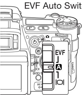
EVF Auto Switch
This option controls the auto-display function in the recording and movie mode (p. 39). Two setting are available:
Auto EVF/LCD - the EVF's eye sensors switch between the EVF and LCD monitor automatically.
EVF auto on - the LCD monitor is turned off and the eye and grip sensors activate the EVF when in use. This setting will help conserve battery power. The grip sensor can be disabled in section 4 of the setup menu.
Video Output
Camera images can be displayed on a television (p. 128). The video output can be changed between NTSC and PAL. North America uses the NTSC standard and Europe uses the PAL standard. Check which standard is used in your region to play back images on your television set.
Language
The language used in the menus can be changed.
Custom Setup
One frequently used function can be allocated to the custom position on the function dial. The function is selected in section 2 of the setup menu (p. 130). The following recording functions are available:
| Image size (p. 82) | Flash control (p. 92) |
| Image quality (p. 82) | Color mode (p. 102) |
| Flash mode (p. 86) | Depth-of-field preview (p. 77) |
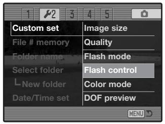
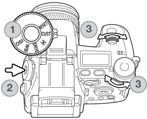
In the recording mode, the function specified in the menu is set with the function dial. To use depth-of-field preview, see page 77.
Turn the function dial to the custom position (1). Press the function button in the center of the dial (2). Turn the front or rear control dials to select the setting (3). Press the shutter-release button partway down or press the function button to complete the operation. Also see camera notes on page 65.
File Number (#) Memory
When file number memory is selected, if a new folder is created, the first file stored in the folder will have a number one greater than the last file saved. This allows multiple folders to be created to store images by category, place, or date, but the image file numbers will be in the order in which they were shot. If the file number memory is disabled, the image file name will have a number one greater than the last image saved in the folder.
If file number memory is active and the memory card is changed, the first file saved to the new card will have a number one greater than the last file saved on the previous card if the new card does not contain an image with a greater file number. If it does, the file number of the new image will be one greater than the greatest on the card.
Folder Name
All recorded images are stored in folders on the memory card. Folder names come in two formats: standard and date.
Standard folders have an eight character name. The initial folder is named 100KM003. The first three digits are the folder's serial number, which will increase by one each time a new folder is created. The next two letters refer to Konica Minolta, and the last three numbers indicate the camera used; 003 indicates a DiMAGE A2.
A date folder name also starts with the three digit serial number and is followed by one register for the year, two register for the month, and two registers for the day: 100YMMDD. The folder 10140223 was created in 2004 on February 23rd.
With the date folder format selected, when an image is recorded a new folder with the day's date will be created. All images recorded that day will be placed in that folder. Images recorded on a different day will be placed in a new folder with the corresponding date. When a new folder is created, the serial number in the
image-file name is reset to 0001 unless file number memory is active. For more information on folder organization and file names, see page 152.

100KM003
(Standard)

10140223
(Date)
Select Folder
This option allows the selection of existing folders. In quick view or playback mode, the images in the selected folder can be viewed or edited. In recording mode, the folder-name option in section 2 of the setup menu must be set to standard form in order to select the folder in which to place the subsequent recorded images.
Except for the all-frames-C cancel-print options in section 3 of the playback menu, changes made with menus only affect the images in the selected folder. To make changes to all images in multiple folders, each folder must be selected and the menu operation repeated for each folder. Folders can be selected temporarily with the view-folder option in section 1 of the playback menu (p. 120). Formatting a memory card in section 1 of the playback menu, erases all folders regardless of whether they are selected or not.
New Folder
This allows the creation of new folders. The folder-name option in section 2 of the setup menu must be set to standard form in order to use the new-folder function. When selected, the electronic keyboard (p. 99) automatically appears so the folder name can be entered. Once the name is typed in and the enter button on the keyboard is highlighted and entered, the folder will be created and the name will be listed in the select-folder option.

Every folder name begins with a three digit index number. When the electronic keyboard activates, three digits will be displayed in the register. This number cannot be changed. Every time a new folder is created, the folder number will increase automatically by one greater than the highest folder number on the memory card. A five-character folder name must be entered after the number; only capital letters, numbers, and the underbar can be used. To cancel the electronic-keyboard display without creating a new folder, press the menu button.
Date and Time Setup
It is important to accurately set the clock. When a still image or a movie clip is recorded, the date and time of the recording are saved with the image and are displayed during playback or can be read with the DiMAGE Viewer software included on the CD-ROM. The camera's clock is also used with data imprinting.
When the Date/Time-set option is selected and entered, the date/time screen will be displayed. The left/right keys of the controller are used to select the item to be changed and the up/down keys are used to change the value. When the date and time have been adjusted, set the clock by pressing the central button of the controller.


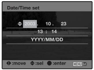
Reset Default
This option resets all camera modes: recording, movie, playback, and setup. To reset the recording or movie modes, see pages 95 and 114. When selected, a confirmation screen will appear; choosing “Yes” resets the following functions and settings, “No” cancels the operation.
| Recording mode | ||
| Display mode | Standard | p. 45 |
| Exposure compensation | 0.0 | p. 59 |
| Flash compensation | 0.0 | p. 59 |
| Digital zoom | Canceled | p. 47 |
| Anti-shake | Active | p. 37 |
| Drive mode | Single-frame advance | p. 61 |
| White balance | Auto | p. 70 |
| Custom-white balance registers | Settings deleted (Daylight) | p. 70 |
| Camera sensitivity (ISO) | Auto | p. 74 |
| Metering mode | Multi-segment | p. 69 |
| Memory | Reset to default settings | p. 72 |
| Contrast compensation | 0 | p. 79 |
| Color-saturation compensation | 0 | p. 78 |
| Filter | 0 | p. 79 |
| Focus area | Wide focus frames | p. 33 |
| Recording menu | ||
| Image size | 3264 X 2448 | p. 82 |
| Image quality | Fine | p. 82 |
| Flash mode | Fill-flash | p. 86 |
| Flash control | ADI | p. 92 |
| AEL button | AE hold | p. 94 |
| Interval setup | 1 min. interval, 2 frames, no delay | p. 96 |
| Bracket setup | 0.3Ev | p. 96 |
| Data imprinting | Off | p. 98 |
| Imprint to | Image + Exif | p. 98 |
| Instant playback | Off | p. 100 |
| Voice memo | Off | p. 101 |
| Color mode | Natural (sRGB) | p. 102 |
| Sharpness | Normal | p. 97 |
| Noise reduction | On | p. 103 |
| Monitor amplification | Auto | p. 104 |
| Monitor amplification (Manual exposure) | Exposure priority | p. 104 |
| Magnification button | Digital zoom | p. 105 |
| DSP setup | DSP | p. 106 |
| Subject Tracking AF | On | p. 106 |
| AE lock | Off | p. 106 |
| Spot AE area | Center spot | p. 107 |
| Direct Manual Focus (DMF) | Off | p. 107 |
| EVF mode | Quality 30fps | p. 108 |
| Movie menu | ||
| Image size | 544 X 408 | p. 113 |
| Frame rate | 15fps | p. 113 |
| Movie mode | Auto select | p. 113 |
| Playback menu | ||
| Display mode | Single-frame playback | p. 40 |
| Index format | 9 frames | p. 121 |
| Playback (Slide Show) | All frames | p. 124 |
| Duration (Slide Show) | 5 seconds | p. 124 |
| Repeat (Slide Show) | No | p. 124 |
| Setup menu | ||
| LCD brightness | Monitor and EVF reset | p. 132 |
| Transfer mode | Data storage | p. 135 |
| EVF auto switch | Auto EVF/LCD | p. 135 |
| Custom setup | DOF preview | p. 136 |
| File number memory | Off | p. 136 |
| Folder name | Standard | p. 137 |
| Audio signals | 1 | p. 141 |
| Focus signal | 1 | p. 142 |
| Shutter FX | 1 | p. 142 |
| Volume | 2 | p. 142 |
| Auto power save | 3 minutes | p. 142 |
| Anti-shake | Display + exposure | p. 143 |
| Full-time AF | Off | p. 143 |
| Grip sensor | On | p. 143 |
| Control dial setup | Front: shutter speed, Rear: aperture | p. 144 |
| Control dial setup (Manual exposure) | Front: shutter speed, Rear: aperture | p. 145 |
| Delete confirmation | “No” | p. 145 |
| Lens accessory | None | p. 145 |
Audio Signals
Every time a button is pressed, an audio signal gives a positive confirmation of the operation. The audio signals can be turned off in section 3 of the setup menu (p. 130). The tone of the signal can also be changed; signal 1 is electrical and signal 2 is mechanical.
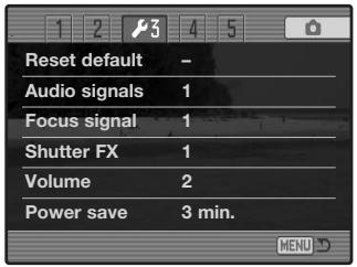
Focus Signals
When the shutter-release button is pressed partway down, an audio signal gives a positive confirmation the AF system has focused. The focus signals can be changed or turned off in section 3 of the setup menu (p. 130). Two tones are available.
Shutter FX
A shutter sound effect gives positive audio confirmation when the shutter is released. The sound effects can be turned off in section 3 of the setup menu (p. 130). Two shutter effects are available. Signal 1 uses the shutter sound from the Dynax/Maxxum 9 SLR. Signal 2 uses a mechanical shutter sound taken from the legendary Minolta CLE.
natural_image
Black MINOLTA camera with visible lens and control buttons (no text or symbols on body)Volume
The volume of the audio signals and sound effects can be increased or decreased in section 3 of the setup menu (p. 130). If the volume is turned off, the audio signals, focus signal, and shutter FX are disabled.
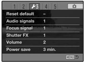
Auto Power Save
The camera will turn off the monitors to conserve battery power if no operation is made within a certain period. The length of this period can be changed to 1, 3, 5, or 10 minutes. To restore power, press the shutter-release button partway down or press the main switch. When the camera is connected to the computer, the auto-power-save period is set to ten minutes. This period cannot be changed.
If an operation is not made within thirty minutes, the camera will shut down. Press the main switch to restore power.
Anti-shake
When the Anti-shake system activates can be changed in section 4 of the setup menu. Two options are available:
Display + Exp. - when the shutter-release button is pressed part-way down, the anti-shake function will activate if on. The affect of the Anti-shake system can be seen in the live image.
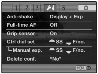
Exposure - Anti-shake is only applied during the exposure and is not apparent in the live image. When the shutter-release button is pressed partway down, wait a moment before taking the picture for the Anti-shake system to stabilize the image.
Full-time AF
Full-time AF continually focuses the camera so the monitor image is always sharp. When the grip sensor is on, full-time AF is activated when the camera is held; the eye sensor is also employed when using the EVF. With the grip sensor off, full-time AF is always active when using the LCD monitor and activated by the eye sensors when using the EVF. When full-time AF is on, the EVF mode (p. 108) frame rate is set to 30fps.
Grip Sensor
The grip sensor conserves power by only activating the full-time AF function when the camera is held. The grip sensor also works with the eye sensors when the EVF auto on option is used, see page 135.
The grip sensor can be turned off when the camera is mounted on a tripod so that full-time AF and the EVF auto on function can be used. Wearing gloves may prevent the grip sensor from working. The sensor is controlled in section 4 of the setup menu.
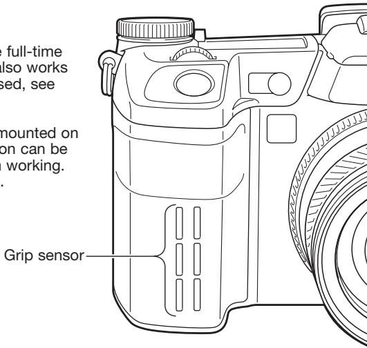
Control Dial Setup
The control dial setup option in section 4 of the setup menu changes the front and rear control dial operation in the P, A, and S exposure modes. Exposure compensation (p. 59) can also be assigned to one of the control dials. Refer to the sections on the exposure modes for more information.
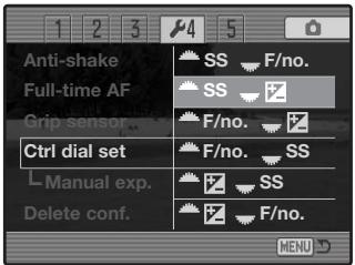
| P (Program exposure) | A (Aperture priority) | S (Shutter priority) | ||||
| Front dial | Rear dial | Front dial | Rear dial | Front dial | Rear dial | |
 | Ps shift | PA shift | Aperture | Aperture | Shutter speed | Shutter speed |
 | Ps shift | Exposure comp. | Aperture | Exposure comp. | Shutter speed | Exposure comp. |
 | PA shift | Exposure comp. | Aperture | Exposure comp. | Shutter speed | Exposure comp. |
 | PA shift | Ps shift | Aperture | Aperture | Shutter speed | Shutter speed |
 | Exposure comp. | Ps shift | Exposure comp. | Aperture | Exposure comp. | Shutter speed |
 | Exposure comp. | PA shift | Exposure comp. | Aperture | Exposure comp. | Shutter speed |
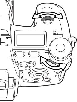
natural_image
Top-down technical diagram of a car dashboard and steering wheel (no text or labels)Control Dial Setup - Manual Exposure
The manual-exposure option in section 4 of the setup menu changes the front and rear control dial operation in the manual (M) exposure mode. Three options are available:
| Front dial | Rear dial | |
 | Shutter speed | Aperture |
 | Aperture | Shutter speed |
 | Programmed manual - both shutter speed and aperture are used to change the exposure following the camera's program line. | |
Delete Confirmation
Each time a delete command is used a confirmation screen appears confirming the action to erase the image data. When this screen opens, the no button is highlighted. This function allows the yes button to be initially highlighted to make deleting images easier. Care should be taken when deleting images as the data cannot be retrieved once erased.
![Delete this frame? Yes No 13:24 2004.02.27 [0024/0093]](/content/2025/01/139770/images/0777493d2a6502fb244ac9cad3352c6847d5b7f87905c3903450fc2fa7ae3bae.jpg)
Lens Accessory
When using this camera with the optional supplementary lenses, the accessory must be specified in section 5 of the setup menu. For more information on the Wide-angle Converter ACW-100 or Telephoto Converter ACT-100, contact your local Konica Minolta dealer. A firmware update is provided with these products to activate this option.
Data-transfer Mode
Read this section carefully before connecting the camera to a computer. Details on using and installing the DiMAGE Viewer software are found in the supplied software manual. The DiMAGE manuals do not cover the basic operation of computers or their operating systems; please refer to the manual supplied with your computer.
System Requirements
For the camera to be connected directly to the computer and used as a mass-storage device, the computer must be equipped with a USB port as a standard interface. The computer and the operating system must be guaranteed by their manufacturers to support USB interface. The following operating systems are compatible with the camera:
Windows 98, 98SE, Me, 2000 Professional, and XP
Macintosh OS 9.0 \~ 9.2.2 and Mac OS X 10.1.3 \~ 10.1.5, 10.2.1 \~ 10.2.8, 10.3 \~ 10.3.1
Compatibility with Windows XP is with the home or professional editions only. Check the Konica Minolta web site for the latest compatibility information:
North America: http://www.konicaminolta.us/
Europe: http://www.konicaminoltasupport.com
Users with Windows 98 or 98 second edition will need to install the driver software on the included DiMAGE software CD-ROM (p. 148). No special driver software is required for other Windows or Macintosh operating systems.
Customers who have bought a previous DiMAGE digital camera and have installed the Windows 98 driver software must repeat the installation procedure. The updated version of the driver software included on the supplied DiMAGE software CD-ROM is required for the operation of the DiMAGE A2 with a computer. The new software will have no affect on the performance of older DiMAGE cameras.
A remote camera driver is supplied in the Windows edition of the DiMAGE Viewer CD-ROM. This driver is not compatible with this camera. When using the DiMAGE Capture software (sold separately), the supplied ferrite core should be attached to the USB cable, see page 167.
Connecting the Camera to a Computer
A fully charged battery should be used when the camera is connected to a computer. The AC adapter (sold separately) is recommended over the use of batteries. For users with Windows 98, read the section on how to install the necessary driver before connecting the camera to a computer.
- Start up the computer. The computer must be on before connecting the camera.
- Open the AV out / USB port cover. Attach the smaller plug of the USB cable to the camera. The plug should be firmly attached.
- Attach the other end of the USB cable to the computer's USB port. The plug should be firmly attached. The camera should be connected directly to the computer's USB port. Attaching the camera to a USB hub may prevent proper operation.
- With a memory card inserted, turn on the camera. A screen will appear to indicate the start of the connection process. When the connection is made, the camera's monitors turn off. To change the card while the camera is connected to a computer, see page 156.
With the camera properly connected to Windows XP or Mac OS X, a window opens to download the image data; follow the instructions in the window. A drive icon, or volume, appears with other operating systems; the volume name varies with memory card and operating system. If the computer does not recognize the camera, disconnect the camera, restart the computer, and repeat the procedure.
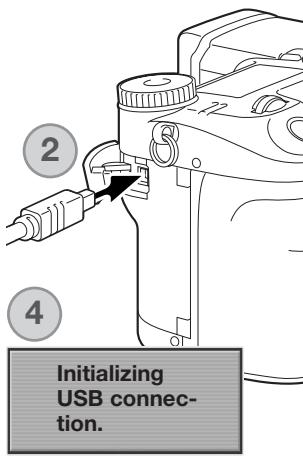
Windows XP
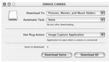
Windows
Mac OSX

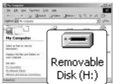
Mac OS
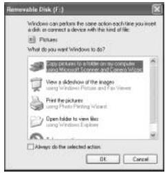
Connecting to Windows 98 / 98 Second Edition
The driver needs only to be installed once. If the driver cannot be installed automatically, it can be installed manually with the operating system's add-new-hardware wizard; see the instructions on the following page. During installation, if the operating system requests the Windows 98 CD-ROM, inset it into the CD-ROM drive and follow the accompanying instructions on the screen. No special driver software is required for other Windows operating systems.
Automatic Installation
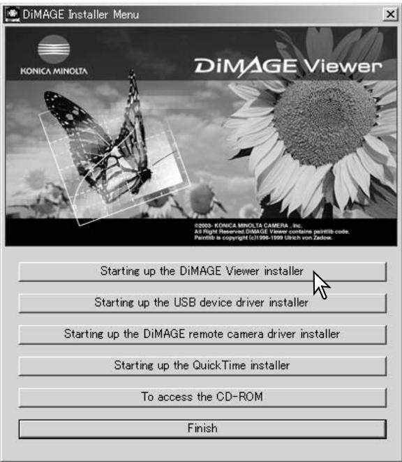
Before connecting the camera to the computer, place the DiMAGE Viewer CD-ROM in the CD-ROM drive. The DiMAGE installer menu should automatically activate. To automatically install the Windows 98 USB driver, click on the starting-up-the-USB-device-driver-installer button. A window will appear to confirm that the driver should be installed; click "Yes" to continue.
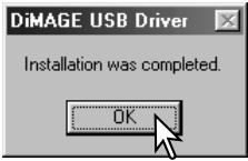
When the driver has been successfully installed, a window will appear. Click "OK." Restart the computer before connecting the camera (p. 147).
Manual Installation
To install the Windows 98 driver manually, follow the instructions in the connecting-the-camera-to-a-computer section on page 147.
When the camera is plugged into the computer, the operating system will detect the new device and the add-new-hardware-wizard window will open. Place the DiMAGE Viewer CD-ROM in the CD-ROM drive. Click "Next."
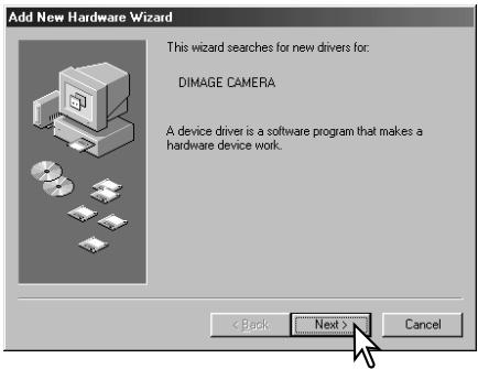
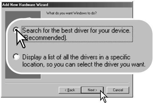
Choose the recommended search for a suitable driver. Click "Next."
Choose to specify the location of the driver. The browse window can be used to indicate the driver location. The driver should be located in the CD-ROM drive at :Win98\USB. When the location is shown in the window, click "Next."
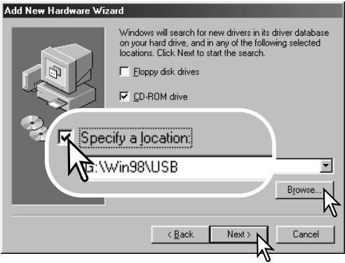
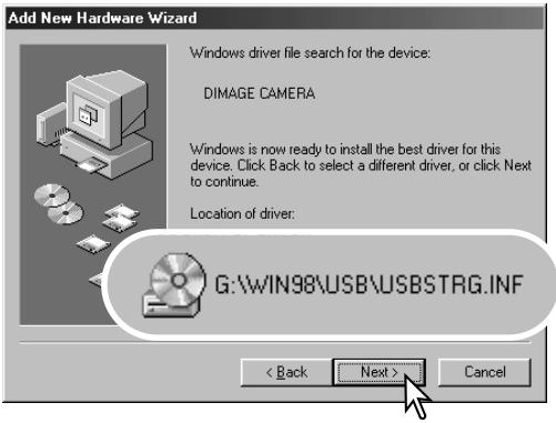
The last window will confirm the driver has been installed. Click “Finish” to close the add new hardware wizard. Restart the computer.
The add new hardware wizard will confirm the location of the driver. One of three drivers may be located: MNLVENUM.inf, USBPDR.inf, or USB-STRG.inf. The letter designating the CD-ROM drive will vary between computers. Click “Next” to install the driver in the system.

Windows has finished installing the software that your new hardware device requires.
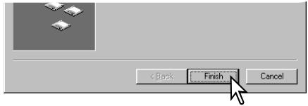
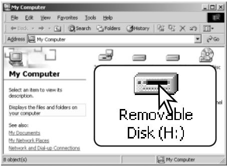
When the my-computer window is opened, a new removable-disk icon will be displayed. Double click on the icon to access the camera's memory card; see page 152.
Quicktime System Requirements
To install QuickTime, follow the instructions in the installer. Macintosh users can download the latest version of QuickTime free of charge from the Apple Computer web site at http://www.apple.com.
IBM PC / AT Compatible
Pentium processor-based PC or compatible computer
Windows 98, Me, 2000, or XP.
128MB or more of RAM
Auto Power Save (data-transfer mode)
If the camera does not receive a read or write command within ten minutes, it will shut down to save power. When the camera shuts down, an unsafe-removal-of-device warning may appear on the computer monitor. Click “OK.” Neither the camera or computer will be damaged in this operation.
Unplug the USB cable and turn off the camera. Remake the USB connection by reattaching the cable and turning the camera on.
Memory Card Folder Organization
natural_image
Close-up of a rectangular electronic component with internal slots and mounting holes (no visible text or symbols)Once the camera is connected to the computer, image and audio files can be accessed by double clicking on icons. Image folders are located in the DCIM folder. To copy images and audio recordings, simply drag and drop the file icon into a location in the computer.
Drive Icon

Dcim

Misc
The misc. folder contains DPOF print files (p. 126).
Files and folders on the memory card can be deleted using the computer. Changing file names or adding other types of data to the card with a computer may cause the camera to malfunction.

100KM003

10140223

102KM_CP
From left to right: standard folder, date folder (p. 137), and copy folder (p. 122).

PICT0001.TIF

PICT0001.THM
TIFF image

PICT0002.MRW

PICT0002.THM
RAW image

PICT0003.JPG
Extra fine, fine, or standard image

PICT0003.WAV
PICT0003's voice-
memo file

PICT0004.JPE

PICT0004.THM
Extra fine, fine, or standard image when using embedded Adobe RGB.

PICT0005.MOV

PICT0005.THM
Movie clip
Image and audio file names begin with “PICT” followed by a four-digit file number and a tif, mrw, jpg, jpe, mov, or thm extension. Voice-memo files have a wav extension and the file name corresponds to its image file. The thumbnail images (thm) are used in camera and DiMAGE Viewer operation.
When a new folder is created, the first three digits in the folder name will be one greater than the largest folder number on the card. When the file number in the image file name exceeds 9,999, a new folder will be created with a number one greater than the greatest folder number on the memory card: e.g. from 100KM003 to 101KM003.
The file number on the image file may not correspond to its frame number on the camera. As images are deleted in the camera, the frame counter will adjust itself to show the number of images on the card and reassign the frame numbers accordingly. The file numbers on the image files will not change when an image is deleted. When a new image is recorded, it will be assigned a number one greater than the largest file number in the folder. File numbers can be controlled with the file-number-memory function in section 2 of the setup menu (p. 136).
Camera Notes
Image files contain exif tag data. This data includes the time and date the image was recorded as well as the camera settings used. This data can be viewed with the camera or the DiMAGE Viewer software.
If a camera image is opened in an image-processing application that does not support Exif tags, and then the image is saved overwriting the original data, the Exif tag information is erased. Some Exif compatible applications rewrite the Exif data preventing the DiMAGE Viewer from reading it. When using software other than the DiMAGE Viewer, always rename the image file to protect the exif tag data.
To view images correctly on your computer, the monitor's color space may need to be adjusted. Refer to your computer manual on how to calibrate the display to the following requirements: sRGB, with a color temperature of 6500K, and a gamma of 2.2.
Although it is recommended to format a CompactFlash card with the camera, a card can be formatted with a computer. The card must be formatted on a Windows system using a FAT or FAT32 file system.
Disconnecting the Camera from the Computer

Never disconnect the camera when the access lamp is lit - the data or memory card may permanently be damaged.
Windows 98 / 98 Second Edition
Confirm that the access lamp is not lit. Turn off the camera and then disconnect the USB cable.
Windows Me, 2000 Professional, and XP

To disconnect the camera, click once on the unplug-or-eject-hardware icon located on the task bar. A small window will open indicating the device to be stopped.
Stop USB Mass Storage Device - Drive(H:)
3:45 PM
Click on the small window to stop the device. The safe-to-remove-hardware window will open. Turn off the camera and then disconnect the USB cable.
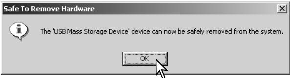
When more than one external device are connected to the computer, repeat the procedure above except right click on the unplug-or-eject-hardware icon. This will open the unplug-or-eject-hardware window after clicking on the small window indicating the unplug-or-eject-hardware routine.
Unplug or eject hardware
3:43 PM
The hardware devices to be stopped will be displayed. Highlight the device by clicking on it then click “Stop.”
A confirmation screen will appear to indicate the devices to be stopped. Clicking "OK" will stop the device.
A third and final screen will appear to indicate the camera can be safely disconnected from the computer; click OK. Turn off the camera and then disconnect the USB cable.
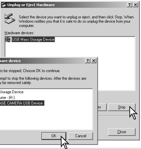
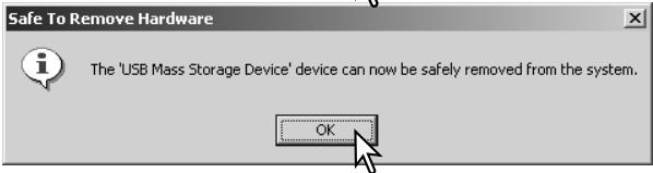

Macintosh
Confirm that the access lamp is not lit and then drag the mass-storage device icon and drop it into the trash. Disconnect the USB cable.
Changing the Memory Card (Data-transfer mode)
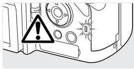
Care should be taken when changing memory cards while the camera is attached to the computer. Data could be lost or damaged if the camera is not properly disconnected. Always confirm the access lamp is out before removing the memory card.
Windows 98 / 98 Second Edition
- Turn off the camera.
- Change the memory card.
- Turn on the camera to remake the USB connection.
Windows Me, 2000 Professional, and XP
- Stop the USB connection using the unplug-or-eject-hardware routine (p. 154).
- Turn off the camera.
- Change the memory card.
- Turn on the camera to remake the USB connection.
Macintosh
- Stop the USB connection by dragging the drive icon into the trash (p. 155).
- Turn off the camera.
- Change the memory card.
- Turn on the camera to remake the USB connection.
Removing the Driver Software - Windows
- Insert a memory card in the camera and connect it to the computer with the USB cable. Other devices must not be connected to the computer during this procedure.
- Right click on the My-computer icon. Select "properties" from the drop-down menu.
Windows XP: from the start menu go to the control panel. Click on the performance and maintenance category. Click "System" to open the system properties window.
- Windows 2000 and XP: select the hardware tab in the properties window and click the device-manager button.
Windows 98 and Me: click the device-manager tab in the properties window.
- The driver file will be located in the universal-serial-bus-controller or other-devices location of the device manager. Click on the locations to display the files. The driver should be indicated with the camera name. Under certain conditions, the driver name may not contain the camera name. However, the driver will be indicated by either a question mark or exclamation point.
- Click on the driver to select it.
- Windows 2000 and XP: click on the action button to display the drop-down menu. Select “uninstall.” A confirmation screen will appear. Clicking “Yes” will remove the driver from the system.
Windows 98 and Me: click the remove button. A confirmation screen will appear. Clicking "Yes" will remove the driver from the system.
- Disconnect the USB cable and turn off the camera. Restart the computer.
PictBridge
Confirm the transfer-mode option in section 1 of the setup menu is set to PTP. Connect the camera to a PictBridge compatible printer using the camera's USB cable. The larger plug on the cable is connected to the printer. Open the AV out/ USB port cover and insert the smaller plug of the cable into the camera. Turn the camera on; the PictBridge screen is displayed automatically.
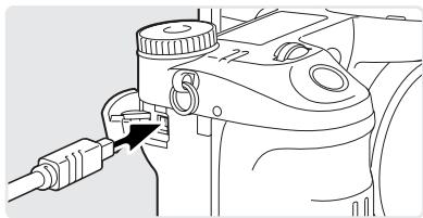
natural_image
Technical line drawing of a camera lens assembly with a connector (no text or symbols)Individual still images can be selected for printing on the PictBridge screen; TIFF, RAW and images with an embedded color profile (p. 102) are not displayed and cannot be selected. For other printing options, see the menu navigation section on page 160.

Use the left/right keys of the controller to display the image to be printed.

Press the up key to select the number of copies to be printed. To deselect an image for printing, press the down key until the number of copies reaches zero. A maximum number of fifty images can be printed.

Repeat the previous steps until all the images to be printed are selected. Press the central button of the controller to continue.
The information (i+) button switches between the single frame and index playback formats on the PictBridge screen. Enlarged playback, activated with the magnification button, can be used to examine image files on the screen.
The number of prints in the print run is displayed as well as the print parameters selected with the menu. See the menu navigation section for more information (p. 160). Press the central button of the controller to begin printing, or press the menu button to return to the PictBridge screen.
Once printing begins, the operation can be canceled by pressing the center of the controller. The printing-finished message indicates the end of the operation; turn the camera off to end the routine.

Notes on Printing Errors
If the battery is exhausted before the print run is complete, printing is canceled. Use a fully-charged battery or the optional AC adapter.
If a minor problem occurs during printing, such as the paper runs out, follow the procedure recommended for the printer; no action is required for the camera. If a major printer error occurs, press the center of the controller to end the routine. Refer to the printer manual for the correct procedure for the printer problem. Check the printer settings before starting again and deselect the images that were printed.
Navigating the PictBridge Menu
Pressing the menu button (1) turns the menu on and off. The four-way keys of the controller (2) move the cursor in the menu. Pressing the central button of the controller enters a setting. The options that can be changed vary with the printer.
MENU

Activate the menu with the menu button.

Use the left/right keys of the controller to highlight the appropriate menu tab; the menu changes as the tabs are highlighted.

Use the up/down keys to scroll through the menu options. Highlight the option whose setting needs to be changed.

With the menu option highlighted, press the right controller key; the settings are displayed with the current setting highlighted. If “Start” is displayed, press the center of the controller to continue.

Use the up/down keys to highlight the new setting.

Press the central button of the controller to select the highlighted setting.
Once a setting has been selected, the cursor will return to the menu options and the new setting will be displayed. To return to the PictBridge screen, press the menu button. Read the following sections on information on the menu options.
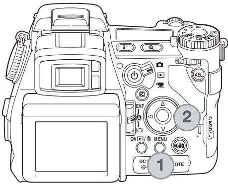
Batch Print
Batch print in section 1 selects all still images on the memory card for printing. Two options are available:
All-frames - to print all images on the card. A screen opens so the number of copies of each image can be specified. A maximum number of fifty images can be printed.
Reset - to cancel changes made with the batch print option or with the print selection screen.
Index Print
An index print of all still images on the memory card can be made. The quality and size of the print can be specified with the camera menu. The number of images per page varies with the printer. The print-setup confirmation screen is displayed before the print routine starts.
Paper Size
The paper size of the print can be specified. The printer-setup option uses the size set with the printer. The sizes option should be set first, see below.
Sizes
To set paper sizes depending on region. This changes the paper-size option above to common sizes used in particular areas.
Layout
The layout of the print can be set. The printer-setup option uses the layout parameters of the printer. Borderless printing can be specified with the camera as well as the number of images per page.
Print Quality
The print quality can be set. The printer-setup option uses the quality set with the printer. The fine quality can be specified with the camera.
Data Print
Data can be printed with the image. The printer-setup option uses the options set with the printer. The date of capture and the file name can be selected for printing. Data printing can also be disabled with the menu.
Printing Notes
The following are the dimensions for postcard, L, and 2L paper sizes in both millimeters and inches for your reference:
| Postcard | 100 X 148mm | 3.9 X 5.9 in. |
| L | 89 X 127mm | 3.5 X 5.0 in. |
| 2L | 127 X 178mm | 5.0 X 7.0 in. |
DPOF Print
DPOF print in section 3 allows still images and an index print selected with the DPOF printing options in section 2 of the playback menu to be printed from a DPOF compatible PictBridge printer. Simply select the start option from the menu to begin the routine.
The number of prints in the print run is displayed; an index print is counted as one. Press the central button of the controller to begin printing, or press the menu button to return to the PictBridge menu.
Once printing begins, the operation can be canceled by pressing the center of the controller. The printing-finished message indicates the end of the operation; press the center of the controller and turn the camera off to end the routine.

Troubleshooting
The section covers minor problems with basic camera operation. For major problems or damage to the camera or charger, or if a problem continues to reoccur frequently, contact a Konica Minolta service facility.
| Problem | Symptom | Cause | Solution |
| The camera will not work. | Nothing displayed on the data panel or the monitors. | The batteries are dead. | Recharge battery (p. 22). |
| The AC adapter is not connected properly. | Check that the adapter is connected to the camera and a live electrical outlet (p. 25). | ||
| “Err” displayed on the data panel. | The camera is hot or it has been left in a very hot environment. | Turn off the camera and allow it to cool. If “Err” is still displayed on the camera after it cools, remove and replace the battery or power cord. | |
| Shutter will not release. | “000” is displayed on the frame counter. | Memory card is full and unable to store an image at the image-quality or image-size setting on the camera. | Insert a new memory card (p. 26), delete some images (p. 41), or change the image-quality or image-size setting (p. 82). |
| No-card warning appears on the monitors. | No memory card in the camera. | Insert a memory card (p. 26). | |
| Pictures are not sharp. | Focus signal is red. | Subject is too close. | Make sure the subject is within the autofocus range (0.5m -∞/1.6 ft -∞) or use the macro mode (p. 49). |
| The camera is in macro mode. | Cancel the macro mode setting (p. 49). | ||
| A special situation is preventing the autofocus system from focusing (p. 35) | Use the focus-lock function to focus on an object at the same distance as the subject (p. 34) or use manual focus (p. 46). | ||
| Pictures are taken indoors or in low-light situations without flash. | Slow shutter speeds result in blurred images when the camera is hand-held. | Use Anti-shake or a tripod, change the camera sensitivity to a higher setting (p. 74), or use the flash (p. 36). | |
| While using flash, the pictures are too dark. | The subject is beyond the flash range (p. 75). | Move closer to the subject or change the camera sensitivity to a higher setting (p. 74). | |
| A shadow appears on the bottom of the image. | Lens hood mount-ed when using flash. | The lens hood blocks the light from the built-in flash. | Always remove the lens hood when using the built-in flash. |
| Shooting data is displayed, but live image is entirely black or white. | Camera set to manual-exposure mode (M). | Shutter speed and aperture combination is extremely under or overexposing the live image. | Change the shutter speed or aperture value until an image appears on the monitor (p. 56). |
| Live image turns black and white. | Camera used under low-light conditions. | With still images, automatic monitor amplification activates under low-light conditions (p. 34). Although the live image is black and white, the recorded still image will be color. In movie recording, the Night Movie mode will record black and white images. | |
| Inaccurate exposures with very bright or dark scenes. | Metering-mode indicator is red. | Subject or scene is outside the metering range of the camera. | Change the camera sensitivity (p. 74) or the light levels. |
If the camera does not function normally, turn it off, remove and reinsert the battery, or unplug and reconnect the AC adapter. Always turn the camera off using the main switch otherwise the memory card may be damaged and camera settings reset.
The camera temperature rises with extended periods of use. Care should be taken to avoid burns when handling the camera, batteries, or memory card.
When using Filters
Polarizing filters and close-up lenses may cause vignetting at the wide-angle range of the lens (below the 50mm mark on the zooming ring). With very powerful close-up lenses, such as a +3 or Minolta No. 2, vignetting may be noticeable below 100mm. Most step-up rings will cause vignetting. The Minolta Step-up Adapter 49mm to 62mm can be used.
About the Lithium-ion Battery Charger Cord
The included AC cord is designed for the current of the sales region. Only use the cord in the region where it was purchased.
| Region | Product code |
| Continental Europe, China, Korea, Singapore (220-240V) | APC-110 |
| Great Britain, Hong Kong (220V-240V) | APC-120 |
| United States, Canada (110V-120V) | APC-130 |
| Japan (100V) | APC-140 |
Attaching the Ferrite core FRC-100
When using an optional remote cord (RC-1000S or RC-1000L), or when operating the camera with the optional DiMAGE Capture software, the cord and USB cable must have the supplied ferrite core (FRC-100) attached. The ferrite core reduces harmful interference.
natural_image
Technical line drawing of a cylindrical mechanical component with internal features and mounting holes (no text or symbols)Slide a thin blunt object under the two latches on the core to open it.
natural_image
Pure mechanical assembly diagram showing a rotating component with no text or symbolsThe core must be placed on the end of the cable that is connected to the camera as shown on the right.
Place the core around the cable and close. Confirm the latches on the core have caught.
Care and Storage
Read this section in its entirety to get the best results from your camera. With proper care, your camera will provide years of service.
Camera Care
- Do not subject the camera to shock or impact.
- Turn off the camera when transporting.
- This camera is neither waterproof nor splashproof. Inserting or removing batteries or the memory card, or operating the camera with wet hands may damage the camera.
- When at the beach or near water, take care not to expose the camera to water or sand. Water, sand, dust, or salt can damage the camera.
- Do not leave the camera under direct sunlight. Do not point the lens directly at the sun; the CCD may be damaged.
Cleaning
- If the camera or the outside of the lens is dirty, gently wipe it with a soft, clean, dry cloth. If the camera or lens comes in contact with sand, gently blow away loose particles. Wiping may scratch the surface.
- To clean the lens surface, first blow away any dust or sand, then gently wipe the lens with a cloth or tissue designed for optics. Use lens-cleaning fluid if necessary.
- Never use organic solvents to clean the camera.
- Never touch the lens surface with your fingers.
Storage
- Store in a cool, dry, well-ventilated area away from dust and chemicals. For long periods of disuse, store the camera in an airtight container with a silica-gel drying agent.
- Remove the batteries and memory card from the camera when not in use for extended periods.
- Do not store the camera in an area with naphthalene or mothballs.
- During long periods of storage, operate the camera occasionally. When taking the camera out of storage, check that the camera is functioning properly before using.
Operating Temperatures and Conditions
- This camera has been designed for use in temperatures from 0^ to 40^ (32°F to 104°F).
- Never leave the camera exposed to extreme high temperatures, such as in a car parked in the sun, or to extreme humidity.
- When taking the camera from a cold to a warm environment, place it in a sealed plastic bag to prevent condensation from forming. Allow the camera to come to room temperature before removing it from the bag.
Memory Card Care and Handling
Memory Cards are manufactured with precision electronic components. The following may cause data loss or damage:
- Improper use of the card.
- Bending, dropping, or subjecting the card to impact.
- Heat, moisture, and direct sunlight.
- Static electrical discharge or electromagnetic fields near the card.
- Removing the card or interrupting the power supply while the camera or a computer is accessing the card (reading, writing, formatting, etc.).
- Touching the electrical contacts of the card with your fingers or metal objects.
- Using the card beyond its life. Purchasing a new card periodically may be necessary.
- When using an IBM Microdrive, do not subject the camera to vibrations.
Konica Minolta has no responsibility for any loss or damage to data. It is recommended that a copy of the card data be made.
Batteries
- Battery performance decreases with temperature. In cold environments, we recommend keeping spare batteries in a warm place, such as the inside of a coat. Batteries can recover their power when they warm up.
- Do not store the battery when it is fully charged.
- When storing the battery for extended periods, recharge it for five minutes every six months. The battery may not be able to be charged if completely exhausted.
- A special built-in, long-life battery supplies power to the clock and memory when the camera is turned off. If the camera resets each time it is turned off, the battery is exhausted. It must be replaced at a Konica Minolta service facility.
- Keep battery and camera charger contacts clean. Dirty contacts can prevent charging. If the contacts become dirty, wipe them with a cotton swab.
LCD Monitor Care
- The LCD monitor and EVF are manufactured using high-precision technology and more than 99.99% of the pixels operate properly. Less than 0.01% of the monitor pixels are displayed as color or bright points; this is not monitor defect and does not affect the recorded image.
- Do not apply pressure to the surface of the LCD monitor; it may be permanently damaged.
- In a cold environment, the LCD monitor may become temporarily dark. When the camera warms up, the display will function normally.
- The LCD monitor may be slow to react in low temperatures or may turn dark in a hot environment. When the camera reaches normal operating temperature, the display will function normally.
- If fingerprints are on the LCD monitor surface, gently wipe with a soft, clean, dry cloth.
Copyright
- TV program, films, video tapes, photographs, and other materials may be copyrighted. Unauthorized recording or duplication of such material may be contrary to copyright laws. Taking pictures or images of performances, exhibitions, etc. is prohibited without approval and can infringe on copyright. Images protected by copyright can only be used under the provisions within the copyright laws.
Before Improtant Events or Journeys
- Check the camera's operation; take test pictures and purchase spare batteries.
- Konica Minolta has no responsibility for any damage or loss incurred by equipment malfunction.
Questions and Service
- If you have questions about your camera or charger, contact your local camera dealer or write to the Konica Minolta distributor in your area.
- Before shipping your camera or charger for repair, please contact a Konica Minolta Service Facility.
Notes
The following marks may be found on the product:

This mark on your camera certifies that this camera meets the requirements of the EU (European Union) concerning interference causing equipment regulations. CE stands for Conformité Européenne (European Conformity).
FCC Compliance Statement
Declaration on Conformity
Responsible Party: Konica Minolta Photo Imaging U.S.A. Inc.
Address: 725 Darlington Avenue, Mahwah, NJ 07430
Digital Camera: DiMAGE A2

Tested To Comply With FCC Standards
FOR HOME OR OFFICE USE
This device complies with Part 15 of the FCC Rules. Operation is subject to the following two conditions: (1) This device may not cause harmful interference, and (2) this device must accept any interference received, including interference that may cause undesired operation. Changes or modifications not approved by the party responsible for compliance could void the user's authority to operate the equipment. This equipment has been tested and found to comply with the limits for a Class B digital device, pursuant to Part 15 of the FCC Rules. These limits are designed to provide reasonable protection against harmful interference in a residential installation.
This equipment generates, uses and can radiate radio frequency energy and, if not installed and used in accordance with the instructions, may cause harmful interference to radio communications. However, there is no guarantee that interference will not occur in a particular installation. If this equipment does cause harmful interference to radio or television reception, which can be determined by turning the equipment off and on, the user is encouraged to try to correct the interference by one or more of the following measures:
- Reorient or relocate the receiving antenna.
- Increase the separation between the equipment and the receiver.
- Connect the equipment to an outlet on a circuit different from that to which the receiver is connected.
- Consult the dealer or an experienced radio/TV technician for help.
Do not remove the ferrite cores from the cables.
This Class B digital apparatus complies with Canadian ICES-003.
Index
AC adapter, 25, 67, 147
Adobe RGB, 2, 102, 103, 152
Auto focus
Continuous, 46
Flex Focus Point (FFP), 48, 49, 107
Full-time, 143
Single-shot, 46
Subject Tracking, 46, 106
Signals, 35, 46
Anti-shake, 37, 143
Auto power save, 24, 142, 151
Battery
Care and storage, 4, 170
Changing, 23
Charging, 4, 5, 22
Condition, 24
Camera
Body, 14
Strap, 20
Camera sensitivity (ISO), 55, 56, 74, 75
Color mode, 2, 102, 103, 136
Color saturation compensation, 62, 78
Continuous advance
Bracketing, 62
High speed, 64
Standard, 64
UHS, 64
Contrast compensation, 62, 79
Copy, 122, 152
Data panel, 17
Data imprinting, 98
Date and time
Displayed, 19, 153
Setup, 20, 138
Delete, 41, 100, 119
Depth-of-field preview, 77, 136
Digital Effects
Bracket, 62
Controller, 78-79, 179
Diopter adjustment, 29
Display
Enlarged, 43
Formats, 42, 45
Histogram, 19, 40, 41
Index, 42, 121
Playback, 19
Recording, 18, 45
DMF (Direct Manual Focus), 105, 107
DPOF print, 126-127, 152
Electronic keyboard, 98, 99, 138
Ev, 59, 111
EVF mode, 108, 134, 143
Exposure
Bulb, 57
Compensation, 59, 110
Lock, 50, 94, 106
Metering, 69, 107
Exposure modes
Aperture priority, 54, 144
Auto, 32, 52
Digital Subject Programs, 58, 106
Manual, 56, 57, 104, 145
Program, 51, 144
Shutter priority, 55, 144
Program manual, 145
Program shift, 56
External power supplies, 25, 177, 178
File organization, 152
Filter, 62, 79, 179
Flash
Attaching, 75, 76, 88
Compatible flash units, 75, 93
Compensation, 59, 110
Metering, 92-93
Range, 36, 75
Signals, 36
Terminal, 76
Flash modes
Fill-flash, 86
Manual, 92-93
Rear sync, 87
Red-eye reduction, 86
Remote, 88-91
Slow shutter sync., 87
Wireless, 88-91
Flex Digital Magnifier, 105, 133
Flex Focus Point (FFP), 48, 49, 107, 133
Focus lock, 34, 35
Focus signals, 35, 46
Folder
Create, 138
Name, 19, 137, 152-153
New, 138
Organization, 152-153
Format memory cards, 27, 120, 153
Frame-selection screen, 118
Image
File name, 152-153
Size, 82-83, 85
Quality, 82-84
Interval
Drive mode, 66
Setup, 96
Time-lapse movie, 66
Lock, 121
Macro, 37, 49
Manual focus, 47
Memory, 72-73, 106
Memory card
Changing, 26-27
Format, 27, 120, 153
Monitor
Amplification, 34, 104
Display, 18-19
PictBridge, 158
Playback
Enlarged, 43
Index, 42, 121
Instant, 100
Movie, 44
Single frame, 40-41
Voice memo, 115
Quick View, 40
Recording
Basic operation, 33
Movie, 38, 111-114
Voice memo, 101
Reset
Camera, 139-141
Movie mode, 114
Recording mode, 95
Self-timer, 68
Sharpness, 97
Shortcuts, 65, 132-134
Slide Show, 124-125
Time-lapse movie, 66
White balance
Auto, 70
Calibration, 71, 76
Custom, 70, 76
Light sources, 70, 111
Preset, 70
Technical Specifications
Number of effective pixels:
CCD:
Camera sensitivity (ISO):
Aspect ratio:
Lens construction:
Maximum aperture:
Focal length:
Focusing range (from the CCD):
Filter diameter:
Autofocusing system:
Shutter:
Built-in flash recycling time:
Viewfinder LCD:
Monitor LCD:
Field of view:
A/D conversion:
Recording media:
File formats:
PRINT Image Matching II:
Menu languages:
AV output:
8.0 million
2/3-type progressive primary-color CCD with a total of 8.3 million pixels
Auto and 64, 100, 200, 400, and 800 ISO equivalents
4:3
16 elements in 13 groups
f/2.8 (wide-angle position), f/3.5 (telephoto position)
7.2 - 50.8 mm (35mm equivalent: 28 - 200mm)
0.5 m - infinity (1.6 ft - infinity)
0.25 - 0.6 m (11.8 - 23.6 in) macro mode: telephoto
0.3 - 0.6 m (9.8 - 23.6 in) macro mode: wide-angle
49 mm
Video AF
CCD electronic shutter plus mechanical shutter
5s (approx)
11 mm (0.44 in.) color-filter type VGA full-color display.
46 mm (1.8 inch) low-temperature polysilicon TFT
Approximately 100%
12 bits
Type I and II CompactFlash cards, 170MB, 340MB, 512MB, and 1GB IBM Microdrives.
JPEG, TIFF, Motion JPEG (mov), WAV, and RAW.
DCF 2.0, DPOF, and Exif 2.21 compliant.
Yes
English, German, French, Spanish, and Chinese.
NTSC and PAL
Battery:
Battery performance (recording):
One NP-400 lithium-ion battery
Approx. number of recorded images: 280 frames.
Based on the CIPA standard with a NP-400 lithium-ion battery, full-size images (3264 X 2448), fine image quality, EVF off, LCD monitor on, flash used with 50% of the frames, no instant playback, no voice memo.
Battery performance (playback):
Approx. continuous playback time: 240 min. Based on the CIPA standard with a NP-400 lithium-ion battery, LCD monitor on.
External power source:
AC adapter (AC-1L or AC-11)
External High-Power Battery Pack Kit EBP-100 Battery Pack BP-400
Dimensions:
117.0 (W) X 85.0 (H) X 113.5 (D) mm
4.61 (W) X 3.35 (H) X 4.47 (D) in
Weight:
Approximately 565g (19.8 oz)
(without batteries or memory card)
Operating temperature:
0^ - 40^ (32^ - 104^)
Operating humidity:
5 - 85% (noncondensing)
Lithium-ion Battery Charger BC-400
Input voltage:
AC 100-240V, 50-60Hz
Weight:
86g (3.0 oz.)
Dimensions:
65 (W) X 90 (H) X 30 (D) mm
2.56 (W) X 3.54 (H) X 1.18 (D) in
Lithium-ion Battery NP-400
Voltage:
7.4V, 1500mAh
Weight:
85g (3.0 oz.)
Dimensions:
56.0 (W) X 39.5 (H) X 21.0 (D) mm
2.20 (W) X 1.56 (H) X 0.83 (D) in
Specifications are based on the latest information available at the time of printing and are subject to change without notice.
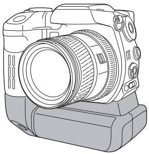
natural_image
Line drawing of a DSLR camera with lens and external casing (no text or symbols)Battery Pack BP-400
The Battery Pack BP-400 is a portable power source for the camera. This accessory uses two NP-400 lithium-ion batteries or six Ni-MH or alkaline batteries to power the camera. For more details on the Battery Pack BP-400 or other accessories listed in this manual, contact your local Konica Minolta dealer.
| Approximate recording performance | |
| With two NP-400 lithium-ion batteries | 560 frames |
| With six 2100mAh Ni-MH batteries | 290 frames |
Based on the following test conditions: full-size images, standard image quality, EVF off, LCD monitor on, flash used with 50 % of frames, no instant playback, no voice memo
| Approximate continuous playback performance | |
| With two NP-400 lithium-ion batteries | 480 minutes |
| With six 2100mAh Ni-MH batteries | 270 minutes |
Based on the following test conditions: LCD monitor on, EVF off.
This product is designed to work with accessories manufactured and distributed by Konica Minolta. Using accessories or equipment not endorsed by Konica Minolta may result in unsatisfactory performance or damage to the product and its accessories.
Filter Examples
Filter levels
with color images

natural_image
Three peaches on a blue plate with a white rim, placed on a textured surface (no text or symbols visible)
natural_image
Close-up of three peaches on a white plate with blue rim, no text or symbols visible
natural_image
Close-up of three peaches on a blue plate (no text or symbols visible)
natural_image
Close-up of two peaches on a blue plate with a white rim, no text or symbols visible
natural_image
Close-up of three peaches on a plate with a blue rim and white background (no text or symbols)
natural_image
Close-up of fresh peaches on a plate with a blue rim and white background (no text or symbols)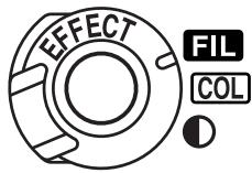

natural_image
Close-up of three red-painted apples on a blue plate (no text or symbols visible)
natural_image
Close-up of three peaches on a blue plate (no text or symbols visible)
natural_image
Close-up of three peaches on a blue plate (no text or symbols visible)
natural_image
Close-up of three red-pink fruits on a blue plate (no text or symbols visible)
natural_image
Close-up of three pink-pink fruits on a blue plate (no text or symbols visible)Filter settings with black and white images.
For more on Filter effects, see page 79.
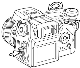
natural_image
Line drawing of a DSLR camera with adjustment knobs and scroll wheel (no text or symbols)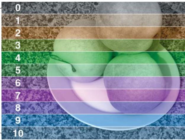

KONICA MINOLTA
We offer support for our digital products 24 hours per day on www.konicaminoltasupport.com.
Camera know-how, image composition, digital image editing: discover more about Konica Minolta's new internet world and visit
www.konicaminoltaphotoworld.com
KONICA MINOLTA CAMERA, INC.
© 2003 Konica Minolta Camera, Inc. under the Berne Convention and the Universal Copyright Convention.
1AG6P1P1613
0-43325-53276-4
9222-2720-11 SY-A312/0401
Printed in Germany
- Before you Begin
- For Proper and Safe Use
- NP-400 Lithium-ion Batteries
- Danger
- Warning
- General Product Warnings and Cautions
- Caution
- Table of Contents
- Names of Parts
- Camera Body
- Camera Notes
- Data Panel
- EFFECT
- RAW QUAL
- SIZE
- #
- 8888+8.8
- 888
- Monitor Display - Recording Mode
- Monitor Display - Quick View & Playback Mode
- Getting Up and Running
- Attaching the Camera Strap
- Removing the Lens Cap
- Attaching the Lens Hood
- Charging the Battery
- Installing and Changing the Battery
- Battery Condition Indicator
- Auto Power Save
- External Power Supplies (sold separately)
- Inserting and Changing a Memory Card
- Turning on the Camera
- Handling the Camera
- Adjusting the Viewfinder and Monitor
- Diopter adjustment
- Setting the Date and Time
- Basic Recording
- Setting the Camera to record Images Automatically
- Basic Recording Operation
- Focus Lock
- Automatic Monitor Amplification
- Focus Signals
- Special Focusing Situations
- Using the Built-in Flash
- Flash Range - Automatic Operation
- Anti-shake System
- Movie Recording
- Display Mode Switch
- Basic Playback
- Viewing Images and Histogram
- Rotating Images
- Deleting Single Images
- Changing the Quick View & Playback Display
- Enlarged Playback
- Viewing Movies
- Advanced Recording
- Display-information Button
- Focus-mode Switch
- Digital Zoom
- Flex Focus Point
- Macro Mode
- Shooting tips
- Exposure-mode Dial
- Program - P
- PROGRAM SHIFT - Ps/Pa
- Auto Recording
- Aperture Priority - A
- Shutter Priority - S
- SHUTTER-SPEED RANGE AND CAMERA SENSITIVITY (ISO)
- Manual Exposure - M
- Bulb Exposures
- Attaching a Remote Cord (sold separately)
- Digital-subject-programs
- Exposure and Flash Compensation
- Using the Function Dial
- Drive Modes
- Bracketing
- Continuous Advance
- Interval
- Self-timer
- Metering Modes
- White Balance
- Daylight
- Tungsten
- Fluorescent
- Cloudy
- Shade
- Flash
- Custom White-Balance Calibration
- Memory - Storing Camera Settings
- Memory Recall
- Camera Sensitivity - ISO
- Flash Range and Camera Sensitivity
- Attaching an Accessory Flash Unit
- System Accessories
- Using the Flash Sync Terminal
- Depth-of-field Preview
- Digital Effects Control
- Color-saturation Compensation
- Contrast Compensation
- Filter
- Recording Menu
- Navigating the Recording Menu
- Image Size and Image Quality
- About Raw Image Quality
- Konica Minolta history
- Notes on Image Size and Resolution
- Flash Modes
- Fill Flash
- Red-eye Reduction
- Rear Flash Sync
- Wireless / Remote Flash
- Notes on Wireless/Remote Flash
- Flash Control
- Flash Notes
- Recording Mode Reset
- Interval Setup
- Bracketing Setup
- Sharpness
- Data Imprinting
- Electronic Keyboard
- Instant Playback
- Voice Memo
- Recording Tips
- Color Mode
- About Adobe RGB
- Noise Reduction
- Monitor Amplification
- Magnification Button
- Flex Digital Magnifier
- DSP (Digital Subject Program) Setup
- Tracking AF
- AE Lock
- Spot AE Area
- Direct Manual Focus
- EVF Mode
- Minolta History
- A short Guide to Photography
- About Exposure and Flash Compensation
- What is an EV?
- Light Sources and Color
- Movie Menu
- Navigating the Movie Menu
- Image Size and Frame Rate
- Movie Mode
- Movie Reset
- Notes on Movie Recording
- Advanced Playback
- Playing Back Voice Memos
- Navigating the Playback Menu
- Frame-selection Screen
- Delete
- Format
- View Folder
- Lock
- Index Playback Format
- Copy
- Slide Show
- About DPOF
- DPOF Setup
- Date Imprint
- Index Print
- Cancel Print
- Viewing Images on a Television
- Setup Menu
- Opening the Setup Menu
- Navigating the Setup Menu
- LCD Brightness
- Shortcut Help
- Digital zoom selected on the menu
- Flex Digital Magnifier selected on the menu
- Transfer Mode
- EVF Auto Switch
- Video Output
- Language
- Custom Setup
- File Number (#) Memory
- Folder Name
- Select Folder
- New Folder
- Date and Time Setup
- Reset Default
- Audio Signals
- Shutter FX
- Volume
- Anti-shake
- Full-time AF
- Grip Sensor
- Control Dial Setup
- Control Dial Setup - Manual Exposure
- Delete Confirmation
- Lens Accessory
- Data-transfer Mode
- System Requirements
- Connecting the Camera to a Computer
- Windows
- Mac OSX
- Connecting to Windows 98 / 98 Second Edition
- Automatic Installation
- Manual Installation
- Quicktime System Requirements
- IBM PC / AT Compatible
- Auto Power Save (data-transfer mode)
- Memory Card Folder Organization
- Disconnecting the Camera from the Computer
- Windows 98 / 98 Second Edition
- Windows Me, 2000 Professional, and XP
- Stop USB Mass Storage Device - Drive(H:)
- Unplug or eject hardware
- Macintosh
- Changing the Memory Card (Data-transfer mode)
- Removing the Driver Software - Windows
- PictBridge
- Notes on Printing Errors
- Navigating the PictBridge Menu
- Batch Print
- Paper Size
- Sizes
- Layout
- Print Quality
- Data Print
- Printing Notes
- DPOF Print
- Troubleshooting
- When using Filters
- About the Lithium-ion Battery Charger Cord
- Attaching the Ferrite core FRC-100
- Care and Storage
- Camera Care
- Cleaning
- Storage
- Operating Temperatures and Conditions
- Memory Card Care and Handling
- Batteries
- LCD Monitor Care
- Copyright
- Before Improtant Events or Journeys
- Questions and Service
- Notes
- Index
- Technical Specifications
- Battery Pack BP-400
- Filter Examples
- KONICA MINOLTA
Brand : KONICA MINOLTA
Model : DIMAGE A2
Category : Digital Camera