MCB-131 - Relais temporisateur numérique ENTES - Free user manual and instructions
Find the device manual for free MCB-131 ENTES in PDF.


| Product Type | Miniature Circuit Breaker (MCB) |
| Brand | ENTES |
| Model | MCB-131 |
| Number of Poles | 1 |
| Rated Current (In) | 32 A |
| Rated Voltage | 230/400 V AC |
| Breaking Capacity | 6 kA |
| Trip Curve | C |
| Frequency | 50/60 Hz |
| Dimensions (H x W x D) | 80 x 18 x 70 mm |
| Weight | 0.1 kg |
| Mounting | DIN rail |
| Material | Thermoplastic housing, copper contacts |
| Operating Temperature | -25°C to +55°C |
| IP Protection | IP20 |
| Standards | IEC 60898-1 |
| Maintenance | None required |
| Safety | Overload and short circuit protection |
| Spare Parts | Not available (integrated unit) |
| Repairability | Not repairable |
| General Information | Suitable for residential and commercial installations |
Frequently Asked Questions - MCB-131 ENTES
User questions about MCB-131 ENTES
0 question about this device. Answer the ones you know or ask your own.
Ask a new question about this device
Download the instructions for your Relais temporisateur numérique in PDF format for free! Find your manual MCB-131 - ENTES and take your electronic device back in hand. On this page are published all the documents necessary for the use of your device. MCB-131 by ENTES.
USER MANUAL MCB-131 ENTES
MCB-130/131 MULTIFUNCTION DIGITAL TIME RELAY
With 2 CO Contact
Operating Manual

A6696 : Rev.2
Dudullu OSB: 1. Cadde; No: 23 34776 Umraniye - ISTANBUL / TURKEY
Tel : +90 216 313 01 10 Fax : +90 216 314 16 15
www.entes.com.tr
Precautions for Installation and Safe Use
If below precautions are not properly observed and carried out, it may result in cases with injury or death.
Disconnect power before working on the device.
When device is connected to the network, do not remove the front panel.
Do not clean the device with solvent or similar items. Only clean with dry cloth.
Verify correct terminal connections before energizing the device.
Install the device on the electrical panel.
Contact your authorized reseller in case problems occur with your device.

- No responsibility is assured by the manufacturer or any of its subsidiaries for any consequences rising out of not following above precautions.
1. INTRODUCTION
MCB-125/126 is a multifunction digital timer with 1 CO contact. It offers wide time adjustment range between 0.1-9999 seconds/minutes.
1.1 Application
MCB-125/126 has 21 different functions with wide adjustable time ranges. The main application area is the industrial and automation control systems.
The device has two dry contacts for START and STOP inputs.
1.1 Product Features
MCB-130/131 has the following features:
85-315 VAC/DC - MCB-130
10-30 VAC/DC - MCB-131
28 different functions
0.1-9999 seconds/minutes time range
2 separate relay outputs (User can assign a function to any relay.)
Start-Stop dry contact inputs
Memorizing remaining time of function in case of a power outage
Custom design LCD with green backlight
SET, ESC, UP, DOWN buttons are located on front panel for easy programming
PK25 DIN Rail mounting
1.2 Hardware Features

To operate functions with external triggering, the device has the necessary START and STOP dry contacts.
1.3.1. Display

- ONSrt : Indicates that the relay will start as closed.
- OFFSrt: Indicates that the relay will start as open.
- Srt-Input Icon: Indicates that the function is started with external input.
- Indicates whether function trigger is Level or Edge.
- Battery
6 and 8. min sec : Indicates whether timing unit is minute or second - Time setting indicator for Star-Delta function
- Numeric Two Digits: Show function number
- Stop: Indicates that stop input is active. Start: Indicates that stop input is active.
- When R1 or R2 relays are activated, the center of the circles are turned on. R and L letters are used
to indicate left or right direction when inverser relay function is selected. Star-Delta: Indicate the output relay state in Star-Delta function. - Indicates the time type of functions.
- In the main menu, it shows the elapsed time.
- In the main menu, it shows the entered time. In the settings menu, it shows the function names.
1.2.2 Button functionality
SET, ESC, UP and DOWN buttons help to select functions and set their times.
UP button goes to previous menu item in Settings Menu and increase selected parameter value.
DOWN button goes to next menu item in Setting Menu and decrease selected parameter value.
SET button is for entering data. When pressed at least 3 seconds, Setting Menu is selected.
ESC button exits from a menu.
1.2.3 Outputs
MCB-130-131 has two changeover relay outputs. According to VDE 0110 and IEC 60947-1 standards; switching capacity of relay output is 8A, 2000VA, 250 V. and maximum electrical life time is 1 × 10^6 .
The user can assign a function to any of the output relays.
1.2.4 Inputs
1.2.4.1 Start Input and Stop Input:
These inputs are voltage-free dry inputs.
Start Input: For some of the functions, output depends on the state of the start input or input pulses from start input. When user shorts two terminals of this input, start input activates. Stop Input: When stop input applies, the timing pauses with stop input's leading edge. When stop input is removed, the timing continues to count from it's last value with stop input's trailing edge. Stop input affects all functions as the same without any exception. When user shorts two terminals of this input, stop input activates.
An Example: This function needs td delay time to release relay. When stop input is applied, it stops counting and saves the time t1. With stop input's trailing edge, counting continues from the saved time t1 until delay time td (Here td=t1 + t2). While stop input is active, the relay doesn't change its
position

U: Supply Voltage
Stop : Stop Input
R : R1 or R2 Rela
Id : Delay Time
t1 : Time elapsed until Stop Input is activated (t1 < td)
t2: Time elapsed after Stop Input is deactivated (td=t1+t2)
2. OPERATING INSTRUCTIONS
When the device is taken out of the box, an installation menu will be displayed. Language and function settings are done in this menu as seen in the figure below. Afterwards, device returns to main menu and starts operating.

flowchart
graph TD
    A["MURULN MENU"] --> B["DIL"]
    B --> C["SETTING PUNC"]
    C --> D["TURICE"]
    D --> E["POSTS OF RECOOLING PROCESSED & EXERCISE"]
    C --> F["RETURN ONION"]
    F --> G["RETURN ONION"]
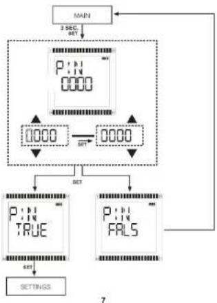
To enter Settings Menu, press SET button for 3 seconds. If password is active, entered the password (It is "0000" by factory default). If password is not active, Settings menu is displayed directly.
flowchart
graph TD
    A["MAN"] --> B["SET"]
    B --> C["PIN 0000"]
    C --> D["SET"]
    D --> E["0000"]
    E --> F["SET+"]
    F --> G["0000"]
    G --> H["SET"]
    H --> I["PIN TRUE"]
    H --> J["PIN FALS"]
    I --> K["SET"]
    J --> L["SETTINGS"]
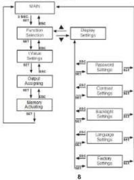
Basic settings map is shown below. There are two main submenus as function selection and display settings.
Function Selection Submenu: A new function is set from function selection menu. In this submenu, user chooses a function, sets t parameter/parameters for selected function; assigns relay output and selects the activation of memory feature to keep remaining timer value.
Display Configurations Submenu: Changing password, adjusting contrast, activating backlight or changing language is done from this submenu.
flowchart
graph TD
    A["MAIN"] --> B["Function Selection"]
    B --> C["Value Settings"]
    C --> D["Output Assigning"]
    D --> E["Memory Activating"]
    E --> F["Display Settings"]
    F --> G["Password Settings"]
    F --> H["Contrast Settings"]
    F --> I["Backlight Settings"]
    F --> J["Language Settings"]
    F --> K["Factory Settings"]
    G --> L["8"]
    H --> L
    I --> L
    J --> L
    K --> L
    L --> M["3.5% INT"]
    L --> N["8% INT"]
2.1 Functions:
- On Delay When supply voltage is applied, "td" begins. At the end of the adjusted time, the output relay is activated

4. Off Delay
When supply voltage is applied, output is activated and "td" time begins. At the end of the adjusted time, the output relay is deactivated. 6. Flasher / Relay ON start
When supply voltage is applied, output relay is activated and "ton" time begins. At the end of ton time, output relay is deactivated and "toff" time begins. This cycle is repeated while supply voltage is applied.  7. Flasher / Relay ON start When supply voltage is applied, "toff" time begins. At the end of ton time, output relay is activated and "ton" time begins. This cycle is repeated while supply voltage is applied.  8. Flasher / Start by external trigger leading edge / Relay ON start This function is controlled by start input after supply voltage is applied. With the leading edge, output relay is activated and remain on during "ton" time. It is deactivated when "toff" time starts. This cycle is repeated while start pulse is on (high).  10. Flasher / Start by external edge - retrigger / Relay ON start This function is controlled by start input after supply voltage is applied. With the leading edge, output relay is activated and remain on during "ton" time. After that, it is deactivated and "toff" time starts. This cycle is repeated until the next edge- retrigger pulse. If a trigger pulse occurs during "ton", time counting is reset and "ton" time counting is restarted. 11. Flasher / Start by external edge - retrigger / Relay OFF start
Function is similar to the ON Start version (function 10) with the exception that the output relay starts as passive. 12. Inverser (right - left) Relay/Relay ON start
When the supply voltage is applied, Relay R1 is activated and "t3" time starts. At the end of "t3" time, Relay R1 is deactivated and "t3" time starts. At the end of "t2" time, R2 is activated and "t4" time starts. At the end of "t4" time, R2 is deactivated and "t1" time starts. At the end of "t1" time, R1 is activated again. This cycle is repeated while supply voltage is on. 13. Inverser (right - left) Relay/Relay OFF start
Function is similar to the ON Start version (function 12) with the exception that the output relay starts as passive.  14.Inverser (right - left) Relay/Start by external trigger leading edge/Relay ON start When the supply voltage is applied and Start Input is activated, Relay R1 is activated and "13" time starts. At the end of "13" time, Relay R1 is deactivated and "13" time starts. At the end of "12" time, R2 is activated and "14" time starts. At the end of "14" time, R2 is deactivated and "11" time starts. At the end of "11" time, R1 is activated again. This cycle is continues while supply voltage is on and Start Input is activated.  15.Inverser (right - left) Relay/Start by external trigger leading edge/Relay OFF start Function is similar to the ON Start version (function 14) with the exception that the output relay starts as passive. 16. Adjustable ON Delay by external trigger leading edge
This function is controlled by start input after supply voltage is applied. When the Start Input is closed, the cycle starts with adjustable "toff" delay time. At the end of delay time, output relay is activated and remain activated during "ton" time. After "ton" time, the output relay is deactivated. If the Start Input is deactivated and activated, function will be reset. bar
| Category | Value | |---|---| | U | ON | | OFF | Off | | S | ON | | OFF | Off | | R | NO | | C | 0 | | t1 | 11 | | t1 | 12 | | t1 | 11 | | t | 1 | | t<12 | Off |19. Adjustable OFF Delay Pulse by External Trigger Leading Edge Re-trigger
This function is controlled by start input after supply voltage is applied. With the leading edge of the Start Input, output relay is activated and "td" time starts. After "td" time, the output relay is deactivated and stays that way until another pulse is applied to the Start Input. If another pulse is applied during "td" time, function is reset.  20. Adjustable OFF Delay Pulse by External Trigger Falling Edge Re-trigger This function is controlled by start input after supply voltage is applied. With the falling edge of the Start Input, output relay is activated and "td" time starts. After "td" time, the output relay is deactivated and stays that way until another pulse is applied to the Start Input. If another pulse is applied during "td" time, function is reset.  21. Impuls Relay When the device is energized, "t" time starts. At the end of "t" time, output relay activates for 0.5 seconds and then deactivates. The function restars only when the supply voltage is removed and applied again.  22. Dual Time ON Delay When the device is energized, "t1" time starts. After "t1" time, R1 relay activates and "t2" time starts. After "t2" time, R2 relay activates. The relays stay active until supply voltage is removed. 23. Dual Time OFF Delay
When the device is energized, R1 and R2 relays activate and "t1" time starts. After "t1" time, R1 relay deactivates and "t2" time starts. After "t2" time, R2 relay deactivates. The function starts again if the supply voltage is removed and applied again. 24. Up Counter-1
After the device is energized, it starts to count with the first applied leading edge. When the pulse number equals to the adjusted "t" number, output relay activates. The output relay stays active until the user sets a new "t" number from the menu or supply voltage is removed and reapplied. 25. Down Counter
This function is controlled by start input after the supply voltage is applied. When start input is applied, counting down starts from the selected value. When this value reaches zero, the output relay activates, if control input retriggered, the output relay de-activates and the function is reset. If the Start Input is triggered before the countdown is finished, function is not affected. If the supply voltage is removed and reapplied, counting starts again. 26. Up Counter-2
Function is similar to the Up Counter-1 function with the exception that the user can adjust how long the output is going to stay active. 27. Latch (Start-Stop) Relay
This function is controlled by start input after the supply voltage is applied. This function does not require any timing value. When start input is applied, relay activates until a second pulse from start input. After receiving the second start input signal, relay deactivates until a third pulse from the start input. This process is repeated while the supply voltage is applied. 28. Star Delta Timer
When the device is energized, R1 relay (star relay) is activated and the t_A time begins. When the t_A time is complete, R1 is deactivated and the second time delay t_A begins. When the t_A time is complete, R2 relay (delta relay) activates, R2 relay stays active while the supply voltage is applied. When the supply voltage is removed and reapplied, function 2.2 Settings
2.2.1 Function Selection:
Function sub-menu is reached by pressing SET button in Settings menu. The functions that the device offers can be browsed with UP or DOWN buttons. The user selects the desired function enters its adjustment menu by pressing SET button. natural_image
Pure diagram of three vertical bars with arrows indicating direction, no text or symbols presentnatural_image
Pure diagram of two parallel lines with vertical bars and a central shaded region, no text or symbols present.natural_image
Pure diagram of parallel lines with vertical bars and curved shapes, no text or symbols present2.2.2 Time Setting :
After selecting the function, user sets t value/values according to the application need. Time range for "t" is between 0.1 seconds-9999 seconds and 0.1 minutes-9999 minutes. Setting starts from left digit towards right digit. User uses UP button to increase value of the digit and DOWN button to decrease. The user presses SET button to move to the next digit on the right and the ESC button to move back to a previous digit. After entering a number, user selects unit (minutes or seconds) by pressing UP or DOWN. Finally, the selected values are stored by pressing SET button. Example Time Setting (0.1 - 9.9) : flowchart
graph LR
    A["0000"] -->|SET| B["0000"]
    B -->|SET| C["0020"]
    C -->|SET| D["0030"]
    D -->|SET| E["0038"]
    E -->|SET| F["... dk"]
    style A fill:#f9f,stroke:#333
    style B fill:#f9f,stroke:#333
    style C fill:#f9f,stroke:#333
    style D fill:#f9f,stroke:#333
    style E fill:#f9f,stroke:#333
    style F fill:#f9f,stroke:#333
flowchart
graph LR
    A["2000"] --> B["2500"]
    B --> C["2570"]
    C --> D["2578s"]
    style A fill:#f9f,stroke:#333
    style B fill:#f9f,stroke:#333
    style C fill:#f9f,stroke:#333
    style D fill:#f9f,stroke:#333
2.2.3 Assigning Output
User is free to choose output relay (R1 or R2) for ON DELAY, DUAL TIME, COUNTER, FLASHER, SINGLE SHOT, ONE SHOT function groups. User should assign R1 or R2 relay as output when configuring a function. After assigning, unassigned output will be an instantaneous contact. It means that it will activate whenever supply voltage is applied as shown in the diagram below.  U : Supply voltage (terminals: 1-3) R : Relay 1 (terminals: 7-9) or Relay 2 (terminals: 10-12) (not assigned output)2.2.4 Memory
Device has an internal memory. If the memory option is activated while setting 2nd, 3rd, 6th, 7th, 8th, 9th, 10th, 11th, 12th, 13th, 14th, 15th and 26th functions; elapsed time and relay positions will be stored when the power goes out. When the power comes back on, the device continues from the stored time and relay position. If the memory option isn't activated while setting a function, elapsed time and relay positions are not stored in case of a power outage and the device starts the function from the start when the power comes back on. FUNCTION SETTINGS ON Delay : flowchart
graph TD
    A["MAIN"] --> B["FUNCTN SAVE 01"]
    B --> C["OUT R1 01"]
    B --> D["OUT R2 01"]
    C --> E["SET"]
    D --> F["SET"]
    G["SETTING FUNC"] --> H["ON"]
    H --> I["DELY 01"]
    I --> J["0038 01"]
    J --> K["0000 0000."]
    K --> L["ESC"]
    style A fill:#f9f,stroke:#333
    style B fill:#ccf,stroke:#333
    style C fill:#cfc,stroke:#333
    style D fill:#fcc,stroke:#333
    style E fill:#ffc,stroke:#333
    style F fill:#cfc,stroke:#333
    style G fill:#fcc,stroke:#333
    style H fill:#cfc,stroke:#333
    style I fill:#cfc,stroke:#333
    style J fill:#cfc,stroke:#333
    style K fill:#cfc,stroke:#333
    style L fill:#cfc,stroke:#333
flowchart
graph TD
    A["SETTING FUNC"] --> B["FLASHR"]
    B --> C["0038-06"]
    C --> D["0000-0000."]
    D --> E["SET↓↑ENC"]
    E --> F["-00 18-06"]
    F --> G["0000-0000."]
    G --> H["MAIN"]
    H --> I["FUNCTN SAVE 05"]
    I --> J["MEMORY ACTV 05"]
    J --> K["MEMORY PASV 06"]
    K --> L["SET"]
    L --> M["R2"]
    M --> N["OUT R1 06"]
    N --> O["↓LT"]
    O --> P["OUT R2 06"]
flowchart
graph TD
    A["MAIN"] --> B["FUNCTN SAVE 18"]
    B --> C["0038 min 18"]
    C --> D["OUT R1 18"]
    D --> E["SET"]
    E --> F["ENC SET"]
    F --> G["SINGLE.T SHOT 18"]
    G --> H["SETTING FUNC"]
    H --> I["SET"]
    I --> J["ESC SET"]
    J --> K["0000→0000."]
    K --> L["SET"]
    L --> M["ESC SET"]
    M --> N["OUT R2 18"]
    N --> O["SET"]
    O --> P["ESC SET"]
flowchart
graph TD
    A["MAIN"] --> B["FUNCTN SAVE 16"]
    B --> C["OUT R1 16"]
    B --> D["OUT R2 16"]
    C --> E["0038-16"]
    D --> F["0000-16"]
    E --> G["0000"]
    F --> H["0000"]
    G --> I["0000"]
    H --> J["0000"]
    I --> K["0000"]
    J --> L["0000"]
    K --> M["0000"]
    L --> N["0000"]
    M --> O["0000"]
    N --> P["0000"]
    O --> Q["0000"]
    P --> R["0000"]
    Q --> S["0000"]
    R --> T["0000"]
    S --> U["0000"]
    T --> V["0000"]
    U --> W["0000"]
    V --> X["0000"]
    W --> Y["0000"]
    X --> Z["0000"]
    Y --> AA["0000"]
    Z --> AB["0000"]
flowchart
graph TD
    A["SETTING FUNC"] --> B["0038_2"]
    C["RIGHT LEFT"] --> D["0000→0000_2"]
    E["EQUAL PULS"] --> F["0088_2"]
    G["MAIN"] --> H["FUNCTN SAVE_2"]
    I["MEMORY ACTV"] --> J["0000→0000_2"]
    K["MEMORY PASV"] --> L["0078_2"]
    B --> M["0000→0000_2"]
    D --> N["0000→0000_2"]
    F --> O["0000→0000_2"]
    J --> P["0000→0000_2"]
    L --> Q["0000→0000_2"]
2.2.5 Display Settings :
In this submenu, user can change password, contrast, backlight and language settings and return to factory default settings. In Password submenu, user can activate or deactivate the password. To change password, the user should first enter current password, then new password twice. In Contrast menu, user can change contrast level from 1 to 5. In Backlight menu, user can choose a setting from "always on", "always off", "on for 5 seconds", on for 10 seconds" and "on for 20 seconds" options. In Language menu, device supports 5 languages as Turkish, English, German, French, Spanish. flowchart
graph TD
    A["SETTING RSP"] --> B["PIN"]
    B --> C["CONTINS"]
    C --> D["BL CHEY"]
    D --> E["URIGAR DE"]
    E --> F["FCFORD SETT"]
    F --> G["PIN"]
    G --> H["CONTINS"]
    H --> I["BL CHEY OFF"]
    I --> J["BL CHEY 20..."]
    J --> K["FRENCH"]
    K --> L["SPRING"]
    L --> M["PRASE LOT2"]
    M --> N["COMPAR YES"]
    N --> O["ENGLISH"]
    O --> P["TURISH"]
    P --> Q["COPIER SETT"]
    Q --> R["CHANGE"]
    R --> S["CURRENT CHANGE"]
    S --> T["CURRENT CHANGE"]
    T --> U["CURRENT CHANGE"]
    U --> V["CURRENT CHANGE"]
    V --> W["CURRENT CHANGE"]
    W --> X["CURRENT CHANGE"]
    X --> Y["CURRENT CHANGE"]
    Y --> Z["CURRENT CHANGE"]
flowchart
graph TD
    A["MAIN"] --> B["Function Selection"]
    B --> C["SET"]
    C --> D["ESC"]
    D --> E["Display Configurations"]
    E --> F["SET"]
    F --> G["ESC"]
    G --> H["F1"]
    H --> I["SET"]
    I --> J["ESC"]
    J --> K["F1S"]
    K --> L["SET"]
    L --> M["ESC"]
    M --> N["setting t"]
    N --> O["SET"]
    O --> P["ESC"]
    P --> Q["Output Assigning"]
    Q --> R["SET"]
    R --> S["ESC"]
    S --> T["Memory Activating"]
    T --> U["SET"]

    A --> V["Password Setting"]
    V --> W["SET"]
    W --> X["ESC"]
    X --> Y["Password Activation"]
    Y --> Z["SET"]
    Z --> AA["ESC"]
    AA --> AB["Password Passive"]
    AB --> AC["SET"]

    A --> AD["Contrast Setting"]
    AD --> AE["SET"]
    AE --> AF["ESC"]
    AF --> AG["Backlight Setting"]
    AG --> AH["SET"]
    AH --> AI["ESC"]
    AI --> AJ["Language Setting"]
    AJ --> AK["SET"]
    AK --> AL["ESC"]
    AL --> AM["Factory Setting"]

    V --> AN["1"]
    AN --> AO["5"]

    V --> AP["Backlight ON"]
    AP --> AQ["SET"]

    V --> AR["Backlight OFF"]
    AR --> AS["SET"]

    V --> AT["Backlight 5 SEC"]
    AT --> AU["SET"]

    V --> AV["Backlight 10 SEC."]
    AV --> AW["SET"]

    V --> AX["Backlight 30 SEC."]
    AX --> AY["SET"]

    V --> AZ["English"]
    AZ --> BA["SET"]

    V --> BB["Turkish"]
    BB --> BC["SET"]

    V --> BD["Deutch"]
    BD --> BE["SET"]

    V --> BF["French"]
    BF --> BG["SET"]

    V --> BH["Spanish"]

    V --> BI["English"]

    V --> BJ["English"]

    V --> BK["English"]

    style A fill:#f9f,stroke:#333
    style B fill:#ccf,stroke:#333
    style K fill:#cfc,stroke:#333
    style L fill:#fcc,stroke:#333
    style M fill:#cff,stroke:#333
    style N fill:#ffc,stroke:#333
    style O fill:#ffc,stroke:#333
    style P fill:#ffc,stroke:#333
    style Q fill:#ffc,stroke:#333
    style R fill:#ffc,stroke:#333
    style S fill:#ffc,stroke:#333
    style T fill:#ffc,stroke:#333
    style U fill:#ffc,stroke:#333
    style V fill:#ffc,stroke:#333
    style W fill:#ffc,stroke:#333
    style X fill:#ffc,stroke:#333
    style Y fill:#ffc,stroke:#333
    style Z fill:#ffc,stroke:#333
    style AA fill:#ffc,stroke:#333
    style AB fill:#ffc,stroke:#333
    style AC fill:#ffc,stroke:#333
    style AD fill:#ffc,stroke:#333
    style AE fill:#ffc,stroke:#333
    style AF fill:#ffc,stroke:#333
    style AG fill:#ffc,stroke:#333
    style AH fill:#ffc,stroke:#333
    style AI fill:#ffc,stroke:#333


- Precautions for Installation and Safe Use
- - No responsibility is assured by the manufacturer or any of its subsidiaries for any consequences rising out of not following above precautions.
- INTRODUCTION
- Application
- Product Features
- Hardware Features
- Inputs
- OPERATING INSTRUCTIONS
- Functions:
- On Delay / Start by external trigger leading edge
- On Delay / Start by external edge re-trigger
- Off Delay
- Off Delay / Start by external trigger trailing edge
- Flasher / Relay ON start
- Flasher / Start by external edge - retrigger / Relay OFF start
- Inverser (right - left) Relay/Relay ON start
- Inverser (right - left) Relay/Relay OFF start
- Adjustable ON Delay by external trigger leading edge
- Adjustable OFF Delay Pulse by External Trigger Leading Edge Re-trigger
- Dual Time OFF Delay
- Up Counter-1
- Down Counter
- Up Counter-2
- Latch (Start-Stop) Relay
- Star Delta Timer
- Settings
- Function Selection:
- Time Setting :
- Assigning Output
- Memory
- Display Settings :
Brand : ENTES
Model : MCB-131
Category : Relais temporisateur numérique