
Canonet - Camera CANON - Free user manual and instructions
Find the device manual for free Canonet CANON in PDF.
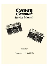


| Product Type | 35mm Rangefinder Camera |
| Lens | 40mm f/1.7 (estimated) |
| Shutter | Copal leaf shutter, speeds 1/4 - 1/500 sec |
| Focus | Manual focusing via coupled rangefinder |
| Exposure | Manual exposure with built-in selenium light meter (estimated) |
| Viewfinder | Bright frame finder with parallax correction |
| Film Format | 35mm (135 film) |
| Flash | Hot shoe and PC sync terminal |
| Dimensions | Approx. 130 × 75 × 60 mm |
| Weight | Approx. 600 g |
| Power Source | None (fully mechanical); optional battery for light meter (PX625, estimated) |
| Main Functions | Manual focus, manual aperture and shutter speed, film advance lever, rewind knob, self-timer |
| Care and Cleaning | Clean lens with soft brush and lens cloth; store in dry, dust-free environment |
| Safety | Do not disassemble the camera; avoid dropping or exposing to moisture |
| Spare Parts and Repairability | Parts available from vintage camera specialists; repairs recommended by experienced technicians |
| General Information | Classic 35mm rangefinder from the 1960s-70s, known for its compact design and sharp lens. |
Frequently Asked Questions - Canonet CANON
User questions about Canonet CANON
0 question about this device. Answer the ones you know or ask your own.
Ask a new question about this device
Download the instructions for your Camera in PDF format for free! Find your manual Canonet - CANON and take your electronic device back in hand. On this page are published all the documents necessary for the use of your device. Canonet by CANON.
USER MANUAL Canonet CANON

Includes:
Canonet 1, 2, 3 (1962)
CANON REPAIR MANUAL
CANONET
(REFERENCE NO. C-30208)
CANON CAMERA COMPANY, INC.
TOKYO, JAPAN
TABLE OF CONTENTS
TOP COVER 1,7
SHUTTER BUTTON 1
BASE PLATE 1
TRIGGER LEVER 1
REWIND CRANK 1
WINDING MECHANISM (cf.p.5)
| B 1077 | Screw |
| B 1413 | Screw |
| S 6258 | Screw X5 |
EXPLODED VIEW
of
CANONET

PARTS LIST
| WINDING MECHANISM (cf. p.4) | W 5222YS 1371 | Washer xNRetaining Washer | |
| C 9262-09 | Base Plate (B. P.) | ||
| C 9263 | Gear (B. P.) | ||
| C 9264 | Feeding Gear (B. P.) | ||
| C 9265 | Film Rewind Release Lever (B. P.) | ||
| C 9266-11 | Wind Device (B. P.) | ||
| C 9267 | Lever (B. P.) | ||
| C 9268 | Sprocket Gear (B. P.) | ||
| C 4005 | Collar | ||
| C 4006 | Washer | ||
| C 4007 | Cover | ||
| C 4008 | Spring | ||
| C 4009-03 | Cover | ||
| C 4010-03 | Wind Shaft for Spool Gear | ||
| C 4011 | Gear | ||
| C 4012-03 | Feeding Claw | ||
| C 4014 | Spring | ||
| C 4020 | Wind Lever Shaft | ||
| C 4021 | Pin Face Nut | ||
| C 4022-03 | Spring | ||
| C 4023 | Clutch Lever | ||
| C 4024 | Collar | ||
| C 4035 | Shaft Screw | ||
| C 4036 | Nut | ||
| C 4042 | Spring | ||
| C 4044 | Lever | ||
| C 4049-06 | Spring | ||
| C 4051-03 | Lever | ||
| C 4052 | Spring | ||
| C 4056 | Clutch Shaft | ||
| C 4057 | Spring | ||
| C 4287 | Spring | ||
| C 4314 | Spring | ||
| C 4315 | Collar | ||
| B 1190 | Screw x 6 | ||
| B 1217 | Screw | ||
| B 8135 | Washer | ||
| S 3787 | Screw | ||
| S 3808 | Screw | ||
| p/V 312rj | Washer xN | ||
| Lw 3122J | |||
| W 5221 | Washer | ||
EXPLODED VIEW
of
CANONET

OBJECTIVE LENS
| CU 086 | Front Lens (Unit) |
| CU 087 | Rear Lens (Unit) |
| CU 110 | Helicoid (Unit) |
| CU 111 | Front Panel (Unit) |
| C 9278 | Flash Socket (B. P.) |
| C 9281 | Lever (B. P.) |
| C 9282 | Contact (B. P.) |
| C 9338 | Lattice Window Frame (B. P.) |
| C 4092-06 | Ring for Shutter Charge |
| C 4094 | Light Shield |
| C 4129 | Insulator |
| C 4176-04 | Ring for Shutter Release |
| C 4177 | Intermediate Ring |
| C 4248 | Nut |
| C 4252 | Flange |
| C 4257 | Focusing Knob |
| C 4258 | Window |
| C 4261 | Assemble Collar |
| C 4262 | Pressure Plate |
| C 4267 | Collar |
| C 4299 | Cord Holder |
| C 4300 | Cord Holder |
| C 4311 | Guide Holder x 2 |
| C 4312 | Guidex4 |
| C 4363 | Focusing Ring |
| S 3177 | Screwx2 |
| S 3237 | Screwx2 |
| S 3287 | Screw x 2 |
| S 3307 | Screw x2 |
| S 3507 | Screw |
| S 3557 | Screw x2 |
| S 3787 | Screw x 6 |
| Y 9135 | Shutter Unit |
EXPOSURE METER (cf. pp. 2 & 8)
ES 4003. Photoelectric Cell is included in CU 066 Exposure Meter and is not supplied as a separate part.
EXPLODED VIEW
of
CANONET


PARTS LIST
TOP COVER (cf. p. 1)
C 4240
Eyepiece Holder
C 4241-02
Film Counter Window
G 52^6
Eyepiece
FILM COUNTER (cf. p. 2)
C 4238
Nut
S 3177
Screw
YS 1101
Retaining Washer
YS 1131
Retaining Washer x 3
EXPLODED VIEW
CANONET

PARTS LIST
EXPOSURE METER (cf. pp. 2 & 6) CU 066 Exposure Meter (Unit)
| C 9272 | Shutter Shaft (B. P.) |
| C 9275-05 | Drive Lever Unit (B. P.) |
| C 9277 | Base (B. P.) |
| C 9286 | Lever for Shutter Release (B. P.) |
| C 9289-04 | EE-Calculator (B. P.) |
| C 9412 | Moving Arm (B. P.) |
| C 9413-02 | Moving Arm (B. P.) |
| C 4125 | Insulator |
| C 4126 | Insulator |
| C 4127 | Collar |
| C 4128 | Contact |
| C 4137-03 | Lever for Mask |
| C 4146 | Coil Spring |
| C 4147 | Coil Spring |
| C 4149 | Galvanometer Holder x 2 |
| C 4153-03 | Moving Guide |
| C 4154-04 | Spring |
| C 4155 | Cam |
| C 4156 | Resistor Holder |
| C 4157 | Bearing for Shutter Shaft |
| C 4166 | Spring Holder |
| C 4167 | Coil Spring |
| C 4298 | Connecting Rod |
| C 4301-03 | Coil Spring |
| C 4366 | Nut |
| B 1382 | Screw x 2 |
| B 1435 | Screw |
| B 5031 | Screw x 2 |
| S 1167 | Screw x3 |
| S 3207 | Screw x 11 |
| W 2131 | Washer x 4 |
| W 2132 | Washer x 2 |
| YS1 1101 | Retaining Washer x 3 |
| YS: 1131 | Retaining Washer x 4 |
INDEX OF PART NUMBERS
| PART NO. | PAGE | PART NO. | PAGE | PART NO. | PAGE | PART NO. | PAGE |
| CU 066 | 2,8 | C 9431 | 2 | C 4079 | 4 | C 4205 | 2 |
| CU 067 | 2 | C 9487 | 1 | C 4086 | 4 | C 4208 | 3 |
| CU 086 | 6 | C 9488 | 4 | C 4090 | 2 | C 4209 | 3 |
| CU 087 | 6 | C 9503 | 3 | C 4091 | 4 | C 4210-05 | 3 |
| CU 110 | 6 | C 4092-06 | 6 | C 4212 | 3 | ||
| CU 111 | 6 | C 4093 | 1 | C 4215 | 2 | ||
| C 4094 | 6 | C 4216-03 | 3 | ||||
| C 4095-02 | 2 | C 4221-02 | 3 | ||||
| C 4096-05 | 4 | C 4238 | 7 | ||||
| C 4002 | 1 | C 4098 | 1 | C 4240 | 7 | ||
| C 4005 | 5 | C 4099 | 1 | C 4241-02 | 7 | ||
| SM 0377 | 2,3 | C 4006 | 5 | C 4100 | 2 | C 4248 | 6 |
| C 4007 | 5 | C 4101 | 1 | C 4257 | 6 | ||
| C 4008 | 5 | C 4102 | 1 | C 4258 | 6 | ||
| C 4009-03 | 5 | C 4103 | 1 | C 4261 | 6 | ||
| C 4010-03 | 5 | C 4104 | 1 | C 4262 | 6 | ||
| C 4011 | 5 | C 4106 | 1 | C 4267 | 6 | ||
| C 4012-03 | 5 | C 4107 | 1 | C 4272 | 3 | ||
| C 9215 | 2 | C 4014 | 5 | C 4108 | 1 | C 4275 | 4 |
| C 9252 | 1 | C 4020 | 5 | C 4109 | 1 | C 4277 | 4 |
| C 9262-09 | 5 | C 4021 | 5 | C 4113-04 | 1 | C 4278 | 4 |
| C 9263 | 5 | C 4022-03 | 5 | C 4114 | 1 | C 4279 | 1 |
| C 9264 | 5 | C 4023 | 5 | C 4115 | 4 | C 4280 | 1 |
| C 9265 | 5 | C 4024 | 5 | C 4117 | 4 | C 4283 | 4 |
| C 9266-11 | 5 | C 4035 | 5 | C 4118 | 1 | C 4285 | 4 |
| C 9267 | 5 | C 4036 | 5 | C 4125 | 8 | C 4287 | 5 |
| C 9268 | 5 | C 4042 | 5 | C 4126 | 8 | C 4290 | 1 |
| C 9269 | 1 | C 4044 | 5 | C 4127 | 8 | C 4298 | 8 |
| C 9270 | 4 | C 4049-06 | 5 | C 4128 | 8 | C 4299 | 6 |
| C 9271 | 4 | C 4051-03 | 5 | C 4129 | 6 | C 4300 | 6 |
| C 9272 | 8 | C 4052 | 5 | C 4137-03 | 8 | C 4301-03 | 8 |
| C 9275-05 | 8 | C 4056 | 5 | C 4146 | 8 | C 4304 | 1 |
| C 9277 | 8 | C 4057 | 5 | C 4147 | 8 | C 4307 | 1 |
| C 9278 | 6 | C 4058 | 1 | C 4149 | 8 | C 4308 | 2 |
| C 9280-03 | 3 | C 4059 | 1 | C 4153-03 | 8 | C 4309 | 4 |
| C 9281 | 6 | C 4061-05 | 1 | C 4154-04 | 8 | C 4310 | 2 |
| C 9282 | 6 | C 4062-05 | 1 | C 4155 | 8 | C 4311 | 6 |
| C 9285-03 | 3 | C 4064 | 1 | C 4156 | 8 | C 4312 | 6 |
| C 9286 | 8 | C 4065 | 1 | C 4157 | 8 | C 4314 | 5 |
| C 9288-04 | 3 | C 4066 | 1 | C 4162 | 1 | C 4315 | 5 |
| C 9289-04 | 8 | C 4067-05 | 1 | C 4166 | 8 | C 4316 | 1 |
| C 9290-10 | 1 | C 4068 | 1 | C 4167 | 8 | C 4317 | 1 |
| C 9338 | 6 | C 4069 | 1 | C 4176-04 | 6 | C 4318 | 6 |
| C 9340 | 3 | C 4070-03 | 1 | C 4177 | 6 | C 4322 | 6 |
| C 9412 | 8 | C 4071 | 4 | C 4179 | 3 | C 4323 | 1 |
| C 9413-02 | 8 | C 4072 | 1 | C 4180 | 3 | C 4325 | 1 |
| C 9425 | 4 | C 4073 | 4 | C 4181-02 | 3 | C 4328 | 4 |
| C 9426 | 3 | C 4075 | 4 | C 4185-04 | 3 | C 4330 | 3 |
| C 9427 | 2 | C 4076 | 4 | C 4186 | 3 | C 4331 | 3 |
| C 9428 | 3 | C 4077 | 4 | C 4187 | 3 | C 4332 | 3 |
| C 9429 | 3 | C 4078 | 4 | C 4192-03 | 3 | C 4333 | 3 |
| PART NO. | PAGE | PART NO. | PAGE | PART NO. | PAGE |
| C 4334 | 3 | S 1167 | 8 | Y 9003 | 1 |
| C 4359 | 2 | S 1218 | 3 | Y 9134 | 6 |
| C 4360 | 3 | S 1518 | 2.4 | Y 9135 | 6 |
| C 4363 | 6 | S 1777 | 2 | ||
| C 4364 | 6 | S.3177 | 1,6,7 | ||
| C 4366 | 8 | S 3207 | 8 | ||
| S 3237 | 6 | ||||
| S 3287 | 6 | ||||
| S 3307 | 2.6 | YS 1101 | 7.8 | ||
| S 3507 | 6 | YS 1131 | 2,3,7,8 | ||
| S 3557 | 6 | YS 1371 | 5 | ||
| B 1011 | 3 | S 3587 | 1 | ||
| B 1077 | 4 | S 3787 | 5,6 | ||
| B 1190 | 5 | S 3808 | 5 | ||
| B 1217 | 2,5 | S 4178 | 1 | ||
| B 1353 | 1 | S 4207 | 3 | ||
| B 1355 | 1 | S 4208 | 2 | ||
| B 1356 | 1 | S 4508 | 4 | ||
| B 1382 | 8 | S 4665 | 1 | ||
| B 1413 | 4 | S 6237 | 2 | ||
| B 1435 | 8 | S 6258 | 2,4 | ||
| B 4021 | 1 | S 6517 | 2 | ||
| B 5031 | 8 | S 6558 | 1 | ||
| B 6050 | 3 | S 6577 | 1 | ||
| B 6107 | 2 | S 6878 | 4 | ||
| B 6139 | 3 | S1-140157 | 2 | ||
| B 8135 | 5 | ||||
| B 8166 | 3 | ||||
| B 8269 | 4 | ||||
| B 8270 | 4 | ||||
| B 8295 | 4 | ||||
| W 1832 | 2 | ||||
| W 2131 | 8 | ||||
| W 2132 | 8 | ||||
| W 2622 | 4 | ||||
| E 8401 | 8 | W 3121 | 5 | ||
| ES 4003 | 6 | W 3122 | 5 | ||
| W 5220 | 3 | ||||
| W 5221 | 3,5 | ||||
| W 5222 | 3,5 | ||||
| G 5229 | 1 | ||||
| G 5230 | 3 | ||||
| G 5231 | 3 | ||||
| G 5232 | 3 | ||||
| G 5233 | 3 | ||||
| G 5234 | 3 | ||||
| G 5235 | 3 | ||||
| G 5236 | 1 |
CANON REPAIR MANUAL
SHUTTER for CANONET 1.2
(REF. NO. 1-30202)
(REF. NO. 1-30206)
CANON CAMERA CO., INC.
TOKYO, JAPAN
SHUTTER for CANONET 1.2

PARTS LIST
| Y13-5001 | Insulator Sheet |
| Y13-5002 | Flash Lead Wire |
| Y13-5003 | Insulator Bush |
| Y13-5004 | Screw |
| Y13-5005 | Spring |
| Y13-5009 | Screw x 3 |
| Y13-5010 | Diaphragm Blade x 5 |
| Y13-5011 | Blade Retaining Plate |
| Y13-5012 | Screw x 2 |
| Y13-5018 | Screw |
| Y13-5023 | Spring |
| Y13-5024 | Screw |
| Y13-5025 | Spring |
| Y13-5026 | Spring |
| Y13-5028 | Washer |
| Y13-5029 | Screw |
| Y13-5030(1.8)~Y13-5030(1.9)/Y13-5030(2.5)Y13-5030(2.6). | Adjusting ScrewSuch numbers (1.8), (1.9)and (2.6) indicate diameter of Adjusting Screws.There are some 9 kind of screw begins with diameter 1. 8^ increase 0. 1^each ends 2. b(j>.Standard screw is Y13-5030(20). |
| Y13-5031 | Screw |
| Y13-5033 | Screw |
| Y13-5040 | Spring |
| Y13-5042 | Retaining Washer x 2 |
| Y13-5044 | Lead Wire |
| Y13-5045 | Hood Ring |
| Y13-5046 | Screw x 3 |
| Y13-5047 | Nut |
| Y13-5140 | Diaphragm Control Ring |
| Y13-5141 | Marking Ring |
| Y13-5142 | Screw x 3 |
| Y13-5143 | Coil Spring |
| Y13-5144 | Steel Ball |
| Y13-5145 | Contact Change Ring |
| Y13-5146 | Rear Cover Plate |
| Y13-5147 | Screw x 2 |
| Y13-5148 | Automatic Diaphragm Lever |
| Y13-5149 | Aperture Scale Ring |
| Y13-5150 | Screw |
| Y13-5151 | Screw |
| Y13-5152 | Click Spring |
| Y13-5153 | Front Cover Plate |
| Y13-5154 | Coupling Shaft |
| Y13-5155 | ASA Cam Ring |
| Y13-5156 | Click Spring |
| Y13-5157 | Shutter Speed Ring |
CANON REPAIR MANUAL
SHUTTER for CANONET 3
(REFERENCE NO. 1-30208)
CANON CAMERA COMPANY INC.
TOKYO, JAPAN
EXPLODED VIEW
REF. NO. 1-30208
of
SHUTTER for CANONET 3

PARTS LIST
| Y13-5001 | Insulator Sheet | Y13-•5044 | Lead Wire |
| Y13-5002 | Flash Lead Wire | Y13--5045 | Hood Ring |
| Y13-5003 | Insulator Bush | Y13-•5046 | Screw x 3 |
| Y13-5004 | Screw | Y13-•5047 | Nut |
| Y13-5005 | Spring | Y13-•5090 | ASA Cam Ring |
| Y13-5006 | Click Spring | ||
| Y13-5007 | Screw | ||
| Y13-5008 | Diaphragm Control Ring | ||
| Y13-5009 | Screw x 3 | ||
| Y13-5010 | Diaphragm Blade x 5 | ||
| Y13-5011 | Blade Retaining Plate | ||
| Y13-5012 | Screw x 2 | ||
| Y13-5013 | Marking Ring | ||
| Y13-5014 | Screw x 2 | ||
| Y13-5015 | Contact Change Ring | ||
| Y13-5016 | Rear Cover Plate | ||
| Y13-5017 | Screw x 2 | ||
| Y13-5018 | Screw | ||
| Y13-5019 | Steel Ball x 2 | ||
| Y13-5020 | Click Spring x 2 | ||
| Y13-5021 | Screw x 2 | ||
| Y13-5022 | Automatic Diaphragm Lever | ||
| Y13-5023 | Spring | ||
| Y13-5024 | Screw | ||
| Y13-5025 | Spring | ||
| Y13-5026 | Spring | ||
| Y13-5027 | Diaphragm Regulating Ring Washer | ||
| Y13-5028 | Screw | ||
| Y13-5029 | Adjusting Screw | ||
| Y13-5030(1.8)- | Such numbers (1.8), (1.9) and (2.6) indicate diameter of adjusting Screws. | ||
| Y13-5030(1.9) | |||
| Y13-5030(2.5) | There are some 9 Kind of Screw begins with diameter 1.8 4 increase 0.1 (j> each ends 2.6 <&. | ||
| Y13-5030(2.6) | Standard screw is Y13-5030(2.0). | ||
| Y13-5031 | Screw | ||
| Y13-5032 | Screw | ||
| Y13-5033 | Screw | ||
| Y13-5034 | Screw | ||
| Y13-5035 | Spacer | ||
| Y13-5036 | B Lock Lever | ||
| Y13-5037 | Screw | ||
| Y13-5038 | Spring | ||
| Y13-5039 | Front Cover Plate | ||
| Y13-5040 | Spring | ||
| Y13-5041 | Coupling Shaft | ||
| Y13-5042 | Snap Ring x 2 | ||
| Y13-5043 | Time Regulating Ring |
EXPLODED VIEW
REF. NO. 1-30208
of
SHUTTER for CANONET 3

When the double-image of the Range-Viewfinder does not align....4
When the Viewfinder Mask does not move smoothly....4
When the Aperture Scale Indicator inside the Range-Viewfinder is out of order....4
When the Red Mark does not appear normally....5
EXPOSURE METER
When the Exposure Meter does not work....6
FILM COUNTER
When the Film Counter does not move forward....7
When the Film Counter does not return....7
WINDING MECHANISM
When the Shutter does not charge....8
When the Trigger Lever does not move....8
When the Trigger Lever runs idle or when it winds many times before the Shutter Button is pressed down....8
When the Shutter Button cannot be pressed down....9
When the Shutter Button does not return to its original position 9
When the film cannot be rewound or when the film catches....9
INCORRECT FOCUS
When the back focus becomes out of focus....10
When the double-image of the Range-Viewfinder does not align....10
RANGE-VIEWFINDER
When the double-image of the Range-Viewfinder does not align, it should be adjusted in the following manner: Turn Screw C4221 when the deviation of the double-image is vertical.
Turn the Eccentric Screw of Lever C9285 to right or left when the deviation of the double-image is horizontal. Care must be taken not to turn C4221 and the Eccentric Screw of C9285 too far as the screw thread may become worn or its calking may become loosened.
Cover Plate C9252 need not be removed when adjusting the double-image.
See Repair Manual p.3.

When the Finder Mask does not move smoothly even after turning the Focusing Ring, the following adjustments should be made.
- Check to see if Spring C4216 has become weak. If so, bend C4216 to give it more strength, or replace it with a new one.
See Repair Manual p.3.
- When the pressure of Holder C4179 is too strong, bend C4179 to weaken it.
See Repair Manual p.3.
- When Viewfinder Mask C9430 is touching Cover Plate C9252, make the proper corrections by bending C9252.
See Repair Manual pp. I S3.
- If Viewfinder Mask C9430 is touching Aperture Scale Index C9429 or EE-Signal C4359, bend either C9429 or C4359 so that there will be a gap of approximately 1 mm.
See Repair Manual pp.2&3.
When the Aperture Scale Indicator inside the Range-Viewfinder is out of order, the following adjustments should be made:
- Make necessary adjustments by turning the Eccentric Screw of Lever C9427. If after adjustment the needle should again become unaligned, it means that the calking of the Eccentric Screw has become loose. In this case, replace C9427.
See Repair Manual p.2.
- If the needle of Aperture Scale Index C9429 is bent and is touching Viewfinder Mask C9430, adjust by bending the needle.
- If Lever C9427 and Lever for Mask C4137 are out of place, adjustments should be made by bending C9427 upwards.
See Repair Manual pp.2&8.
- If Lever C9427 and Arm C9428 are out of place, the upward and downward play of both should be adjusted with a washer.
See Repair Manual pp.2&3.
- If the movement of C9427 is impeded by Lever C9427 and Film Counter Advancing Lever C9431 pressing against it, C9431 should be bent and adjusted so that it will not touch.
See Repair Manual p. 2.
When the Red Mark does not appear normally, that is, when the Red Mark appears even though the Shutter has been set for automatic photography, or when the Red Mark does not appear at all after the lens cap has been put on and the Shutter Button pressed, it may be assumed that something is wrong with the Red Mark itself. In this case, the following adjustments should be made:
- If the movement of Moving Guide C4153 is bad, replace Washer W 2132 x 2, which is under Retaining Washer YS 1131x2 holding C4153, with one of less thickness.
See Repair Manual p.8.
- Adjust the length of EE-Signal C4359 after loosening Screw SI-140157 x 2 securing C4359.
See Repair Manual p.2.
EXPOSURE METER
When the shutter is not released even after the shutter button is pressed down for automatic photography with the shutter speed set at 1/125 or 1/250 in bright sunlight, it may be assumed that the exposure meter has developed some kind of trouble. In this case, the following checks and adjustments should be made.
- Check to see whether the meter needle is in the position shown in the figure with the lens cap on. Then take the lens cap off and see if the needle moves when the lens is pointed towards the light.
See Repair Manual p.2.

- If the needle does not move, the connection between the photoelectric cell and the cord should be checked in the following order:
1) Window C4258 and Lattice Window Frame C9338 are removed by disconnecting Collar C4261 with Tool T06A-C4261.
2) Check whether the cord is firmly connected to Photoelectric Cell ES4003. Make sure that no naked wire is touching the inner side of ES4003.
3) Before tightening C4261, press down on ES4003 with the hand and check to see if the needle moves when light is focused on it.
- If the above conditions are found to be normal but still the needle does not move, Exposure Meter CU066 should be replaced.
FILM COUNTER
If for some reason the winding mechanism becomes faulty and the film counter does not move forward, adjustments should be made in the following manner:
- Check the Spring for Film Counter CU067 and reattach if it has come loose.
See Repair Manual p.2.
- If the movement of the Stop Claw for CU067 is small, the Stop Claw will not mesh with the Ratchet Gear Teeth and this will prevent the Film Counter from moving forward. In this case, the tip of the Stop Claw should be bent.
See Repair Manual p.2.
When the Back Cover is opened, the Film Counter will automatically return to "2". However, if for some reason the Film Counter fails to return when the Back Cover is opened, adjustments should be made in the following manner:
Check to see if the Resetting Lever of Film Counter CU067 is not touching the camera body. If it is found to be touching the camera body, adjust by bending the Resetting Lever.
See Repair Manual p.2.
WINDING MECHANISM
When the camera shows the conditions described below, it may be assumed that the Winding Mechanism has become defective, and so the following adjustments should be made:

When the shutter is not charged even after the Trigger Lever is wound, the following adjustments should be made: Loosen Screw B1190. Float Winding Device C9266-11 and set the Shutter with a pair of tweezers. Then adjust the amount of charge by turning the Eccentric Screw of C9266-11.
See Repair Manual p.5.
When the Trigger Lever does not move, the following checks and adjustments should be made:
- Check to see whether the Screw for the Winding Device is loose.
- Check to see whether Spring C4049 is out of place. If so, reattach.
See Repair Manual p.5.
- If Cone C4090 is caught between Lever C9267 and Lever C4051-03, loosen Screw S1777 and adjust C4090 by turning it to the right.
See Repair Manual pp.2&5
- If Lever C4051-03 does not disengage itself from Lever C4044 when the shutter button is pressed down because Cone C4090 does not go down enough, Screw S1777 should be loosened and adjustments made by turning C4090 to the left.
When the Trigger Lever runs idle or when it winds many times before the shutter button is pressed down, the following checks and adjustments should be made:
- Check to see whether Spring C4042 is out of place. If so, reattach.
See Repair Manual p. 5
If the spindle of Lever C4044 is bent, replace Base Plate C9262-09.
See Repair Manual p. 5
- If the gap between Lever C4044 and Winding Device C9266-11 has become too wide because Lever C4044 has become worn out, adjustments should be made by turning the Hexagonal Eccentric Nut for Base Plate C9262-09 with Spanner 2 for C4041. If this is insufficient, C4044 should be replaced.
See Repair Manual p. 5
When the Shutter Button cannot be pressed down, it should be adjusted in the following manner:
Check to see whether Spring C4049 attached to Lever C4051-03 is out of place and if so, reattach.
See Repair Manual p. 5
When the Shutter Button does not return to its original position after it has been pressed down, the following adjustments should be made:
Check to see whether Cone C4090 is caught between Lever C9267 and Lever C4051-03. If so, loosen Screw SI 777 and make adjustments by turning C4090 to the right.
See Repair Manual pp. 2 & 5.
When the film cannot be rewound or when the film catches, the following adjustments should be made:
Open the Back Cover and set the Rewind Clutch Lever to R. Then check to see whether it will turn both to the left and right by rotating the sprocket manually. If it does not turn, see whether Clutch Lever C4023 is bent, or whether Clutch Shaft C4056 is held down properly by C4023. Then adjust by bending C4023, or replace C4023.
See Repair Manual p. 5.
INCORRECT FOCUS
When the Back Focus becomes out of focus due to some kind of shock, the following adjustments should be made with the use of a 200mm T-Type Collimator:
First, loosen only three of the S3787x4 Screws holding Focusing Ring C4256, determine the proper position by turning C4256, and when the proper position is found, loosen the remaining one S3787 Screw.
Lastly, set the oo of C4256 to the camera's Range-Viewfinder Distance Scale and again tighten all four S3787x4 Screws.
See Repair Manual p. 6
When the double-image of the Range-Viewfinder does not align due to some kind of shock, adjustments should be made after referring to the paragraph on "When the Range-Viewfinder's Double-Image does not align?"
CANON REPAIR GUIDE
SHUTTER for CANONET
(REF.NO.1-30208)
CANON CAMERA CO., INC.
TOKYO, JAPAN
CONTENTS
Disassembling Method
Barrel 4
Shutter Blades 5
Diaphragm Blades 6
Diaphragm Ring 7
Adjusting Method
Release Lever 9
M-Governor 10
Shutter Blades 11
Diaphragm Blades 14
Main Cocking Lever 15
Trouble, Cause & Remedy
It cannot be released 18
Heavy Release 18
It cannot be charged 19
Charge is heavy 20
Diaphragm blades do not return 20
Diaphragm blades do not return smoothly 21
B Full Open 21
B skips 22
One Second Open 22
Slow Skips 22
It cannot be released by self-timer 23
BARREL DISASSEMBLING

Works
Specifications
Taking out Barrel
Fit the nut to the screw.
Taking out nut.
n.b. Use a pincers or pin face screwdriver for the purpose.
Taking out barrel.
Taking out Speed Plate
Taking out speed plate.
Taking out Click Lever for B Set
Taking out Click Lever for B Set.
SHUTTER BLADES DISASSEMBLING


Works
Specifications
Taking out Set Lever
Taking out screw. 1/T
Taking out set lever.
Note: The set lever should be taken out by pushing the top end up with a screwdriver.
Taking out Plate
Taking out screws x 4. A, B, C, D
Taking out plate.
It can be taken out with the shutter blades assembled to the plate.
DIAPHRAGM BLADES DISASSEMBLING

Works
Specifications
Taking out Diaphragm
Taking out screw x 2 (A, B)
Taking out middle plate
Taking out diaphragm blades (5 blades).
Taking out Diaphragm Control Ring
Taking out screw x 3 (C, D, E)
Taking out Diaphragm Control Ring
DIAPHRAGM RING DISASSEMBLING

Works
Specifications
Taking out Screw x 2
Letting Diaphragm Ring Revolve
Taking out screw A and B.
Rotate the diaphragm ring counter-clockwise relative to the shutter body to the position specified in the following diagram.
approximately 5mm
Removing the Diaphragm Ring
The diaphragm ring can be removed at the position where the two 'o' marks align.
Note: Be careful not to lose the bearing ball and spring; the bearing ball provides the auto-click function.
RELEASE LEVER ADJUSTMENT
Disassembly Procedure
1. Removing the M-Governor Driver
1) Remove the spring. 2) Remove the nut.
Remove the nut holding the governor driver with your fingers from the top, ensuring the adjusting tap does not move out of position.
3) Marking
Place a mark on the governor driver and adjusting tap to easily identify the assembly position.
4) Remove the M-Governor Driver. 5) Remove the adjusting tap.
2. Removing the release lever
1) Remove the spring. 2) Remove the release lever.
1. Insertion of shaft must be smooth. 2. There should not be any scratch or roughness on the surface where the release hook touches.


nut


governor driver
adjusting tap

< ^

release lever
Inspection
1. Put MOG-3 on the release lever shaft. 2. Put MOG-3 on the release lever hook part. 3. Fix the release lever and spring. 4. Fix the adjusting tap. 5. Fix the governor driver. 6. Fasten the nut.
Put the mark of the governor driver and adjusting tap together and fasten, holding the governor driver with your fingers so that the position of the tap does not move.
7. Check gearing of release. Refer to the item on how to replace and adjust tension.
8. Fixing B lever.
M-GOVERNOR ADJUSTMENT
How to Disassemble
1. Taking out B lever.
2. Taking out M-Governor Driver.
Refer to the item on how to replace and adjust the release.
3. Removing the segment gear.
1) Screw 2) Segment gear

Screw

Collar

Segment gear
Governor
Anchor
Cog-wheel supporter
Inspection
1. The space between the cog-wheel supporter and the anchor must be less than 0.15 mm.
2. The operation of the anchor and cog-wheel must be smooth.
How to Fix
1. Fixing the governor
1) Place the governor on the plate. 2) Segment gear collar 3) Segment gear 4) Screw 5) When holding the dowel and moving it left and right, it should operate smoothly without any resistance.
dowel for segment gear

Gear space between segment gear and cog-wheel can be adjusted to some extent.
2 Fixing governor driver
Refer to the item how to replace and adjust release lever.
3 Check release gearings.
Refer to the item how to replace and adjust tension.
4 Fixing B lever
SHUTTER BLADES ADJUSTMENT
How to Disassemble
1 Take out the spring from spring hanger.

2 Take out tension lever in the state that shutter is depressed. 3 Take out four screws which fix plate.
(a)

4 Set dowel for M-Governor Driver at the point a little farther near to X than M position.

Scratched blades, dirt, oily, fingerprints
Inspection
1 Plate
1) Put CU087 Rear Lens to the plate.

2) Assembling sub shutter blade
Assemble as shown in the diagram (a)-(d).
3) Assembling shutter blades
Assemble as (a) - (e). clockwise direction.
Assemble the last sub blade on the blade (e).

n.b. Pay attention not to put any fingerprints' on it.
2 Case
Check setting position of M-Governor Driver switching dowell. The position should be a little farther near to X than M position.
3 Assembling plate and case

1) Hold the plate with your left hand as shown in the diagram, and press the release lever in with your forefinger. In this stage pay attention if it is inclined, the assembled blades come off. 2) Hold it in the direction which the case is fitted to the plate, and fit the release lever pin and long hole for the pin.
3) Placing the case and the plate in parallel, assemble in until the height of release pin's top end becomes same level as the oblique lines portion of the diagram.

work (a) and (b)
release pin
4) Assemble synchro side tightly to work (c)
5) Being synchro side closely fitted to work (d)
6) Assemble the other side (synchro wire side.) In this stage assemble after M-Governor Driver is properly set. work (e)
4 Fasten four pieces of screw for the plate.
Refer to the item how to disassemble (3) of this section.
5 Hanging spring for synchro contact.
Refer to the item how to disassemble (1) of this section.
6 Fixing tension lever
Put a little lac to screw hole of tension shaft.
n.b. 1 Put correctly the pieces of washer which have been inserted.
2 Pay attention that lac should not be put to the operation portion.

DIAPHRAGM BLADES ADJUSTMENT
How to Disassemble
1 Taking out plate.
Refer to the item how to replace and adjust shutter blades.
2. Removing the blades retaining plate.
1) Set the diaphragm regulating ring to Auto. 2) Remove the two screws for the blades retaining plate. 3) Remove the blades retaining plate.
Inspection
Check for scratches, dirt, oil, and fingerprints on the blades.
1. Assemble the blades in the direction shown in the diagram, in counterclockwise order.

Blade retaining plate
2. Place the blades in order within the case circle.
3. Fix the blade retaining plate.
4. Fasten the screw for the plate.
5. Check the operation of the blades. They should move smoothly.
6. Fixing plate. Refer to the item on how to replace and adjust shutter blades.

Diaphragm blade
MAIN COCKING LEVER ADJUSTMENT
How to Disassemble
1. Remove the slow governor.
1) Set the cocking lever.
2) Take out three screws for the governor.
3) Take out the governor.
4) Take out washers.

Slow governor
2 Taking out the main cocking lever
1) Take out tension spring.

Tension spring
Take out the spring in the direction of the arrow using a screwdriver.
2) Pull out the main cocking lever.
Note: Pay attention that the synchro contact should not be bent when pulling it out.
Inspection
1 The movement of the piston should be smooth.
2 Every surface should be smooth.
How to Fix
1 Put MOG-3 on the tension.

Put MOG-3 here.
Put a little MOG-3 on the brim.
2 Fix the main cocking lever.
Push in the main cocking lever to the extent that the spring hang tool can be inserted.
3 Hang the spring hang tool to the rise up portion of the tension spring and hang it to portion (a) of the main cocking lever, pulling the spring.

4 Press the main cocking lever completely down.
If it is hard, insert it while pushing the tension spring in the arrow direction with pincers.
n.b. 1 Pay attention as the spring should not be weakened.
2 Pay attention to the bending of the contact.
5 Fix the rear cocking lever.
Put a little lac to the screw hole of the main cocking lever shaft.
n.b. Pay attention as lac should absolutely not be put to the operation portion.

6 Put MOG-3 to the main cocking lever.
Put a little MOG-3 to the (a), (b) portions in the diagram.

7 Gearing of release lever and main cocking lever
1) Set the cocking lever.
2) Letting the
piston operate to the arrow direction and check if it touches to semi-circle.

3) If it touches,
adjust bend-
ing the re-
lease hook
to the arrow direction.
4) Timing of piston, setting of semicircle, tension, and release hook
i As a rule the release and piston should be charged simultaneously,
ii It may have some divergence, however, it should not extremely be different, because it causes that synchro contacts when the contact moves and sets.
iii In that case the piston should charge in the first place.
5) Room
It requires some room space after charge.
TROUBLE, CAUSE & REMEDY
IT CANNOT BE RELEASED.
1 The blades do not move.
1-1 Oil
Clean.
1-2 Metal collapse
Replacement
Refer to the item of shutter blades adjustment.
2 The main cocking lever does not move.
2-1 Creaking main cocking lever shaft
Replacement
Refer to the item of main cocking lever adjustment.
2-2 Rusting main cocking lever
Replacement
the same as the above
3 Inferior Piston Move
3-1 Coming off piston spring
Correct the hanging.
Check the spring movement.
3-2 Adjusting aberration
Refer to the item of main cocking lever adjustment.
3-3 The piston does not move.
Replacement
the same as the above
4 An obstacle be caught in.
Abridged
HEAVY RELEASE
1 Roughness of Release Hook and Main Cocking Lever
1-1 Lack of oil on the touching surface
Lubricate MOG-3 on the surface.
1-2 Roughness of the touching surface
Replacement
Refer to the item of release lever and main cocking lever adjustment.
2 Inferior Operation of
2-1 Bent release lever
Adjustment
Check the gearing of rear release and tension.
3 Inferior Release Ring
2-2 Rusted release lever
Replacement
Refer to the item of release lever adjustment.
3-1 Rough surface of release pin
Polish using oil stone and after that put a little liquid molybdenum.
3-2 Rough surface where touches to the helicoid
The disposal is same as mentioned in 3-1.
3-3 Bent release ring
Rectifying or replacement
IT CANNOT BE CHARGED.
1 Coming off Main Cocking Lever
1-1 Loosened screw
Refer to the item of main cocking lever adjustment.
1-2 So much room space in the tension lever long hole
the same as the above
2 Inferior Piston Move
2-1 The piston does not move.
Refer to the item of main cocking lever adjustment.
2-2 Coming off piston spring
Hang it up and check the effect of spring.
3 Inferior Release Lever Move
3-1 Bent release lever
After adjustment, check the gearing of release and main cocking lever.
Refer to the item of main cocking lever adjustment.
3-2 Inferior release spring
Replace it and refer to the item of release, lever adjustment.
3-3 Rusted release lever
Replace and the rest is same as the above.
CHARGE IS HEAVY.
1 Rough Surface of Main Cocking Lever with Release Lever
1-1 Lack of Lubrication Lubricate MOG-3 to the touching surface.
1-2 Rough surface Replace main cocking lever and release lever. Refer to the item of main cocking lever and release lever adjustment.
2 Creaking Main Cocking Lever Shaft
2-1 Lack of Lubrication Lubricate MOG-3 to the tension shaft. Refer to the item of main cocking lever adjustment.
2-2 Rough tension shaft Replacement the same as the above
2-3 Rusted tension shaft Replacement the same as the above
3 Rear cocking lever touches to rear cover plate.
3-1 Bent rear cocking lever Replacement Refer to the item of main cocking lever adjustment.
4 Inferior M Governor
4-1 Cog-wheel has been detached and it touches to connection plate. Adjustment Refer to the item of M Governor adjustment.
4-2 Loosened segment gear screw Adjustment the same as the above
4-3 Lack of lubrication on cog-wheel Lubrication
DIAPHRAGM BLADES DO NOT RETURN.
1 Oil
Cleaning
2 Stuck Blades
2-1 Inferior stopper position
After adjustment: 1 Stop down fully up to f 16 by manual lever.
2 At this time check if the auto lever moves smoothly without any catching.
2-2 Warping
Replacement
Refer to the item of diaphragm blades adjustment.
2-3 Scratch
Replacement
the same as the above
3 Transformation by Shock
Refer to the item of diaphragm blades adjustment.
4 Detached Spring
Hang it up.
DIAPHRAGM BLADES DO NOT RETURN SMOOTHLY.
1 Oil
2 Inferior Operation of Auto Diaphragm Lever
2-1 Loosened screw abridged
2-2 It touches to the case because of bending. Replace the auto lever.
2-3 Rusted the same as the above
3 Inferior Operation of Manual Diaphragm Lever
3-1 Lubricate and clean.
3-2 Replace in case of inferior riveting.
3-3 Replace in case of rusting.
B FULL OPEN
1 Inferior Governor
Refer to slow skipping.
2 Connection of B Lever and Main Cocking Lever
2-1 Stuck: Replace B lever.
2-2 Rough surface: Replace B lever and main cocking lever. Refer to the item of main cocking lever.
3 Creaking Sector Ring
Most of this trouble being caused by shock.
Replacement
Refer to the item of shutter blades adjustment.
4 An obstacle has been stuck.
abridged
B SKIPS.
1 Inferior Operation of B Lever
Replacement
2 Warped Cam Plate
Rectify.
ONE SECOND OPEN
1 Inferior Governor
1-1 Loosened governor set screw abridged
1-2 Lack of lubrication on anchor Lubricate.
1-3 Aberrant adjustment for anchor Adjust.
1-4 Connection plate is too loose. Replace governor.
1-5 There is an obstacle in gear Rinse by benzine and then lubricate.
2 Creaking Sector Ring
Most of this trouble being caused by shock,
3 An obstacle has been stuck
abridged
SLOW SKIPS.
1 Inferior Governor
1-1 Operation of anchor clutch lever Replace governor.
1-2 Put in anchor clutch lever pin. After being adjusted the bending of clutch lever, and then adjust the clutch space.
1-3 Anchor clutch lever pin is too high, the same as the item 1-2
1-4 Inferior operation of speed change lever Replace governor.
IT CANNOT BE RELEASE SELF-TIMER.
1 Inferior Operation of Clutch Lever
1-5 Loosened reverting of pinion gear Replace governor.
1-6 Creaking of connection plate
1-1 Bent clutch lever Rectify bending.
1-2 Detached clutch lever and sector ring's dowell Adjustment
2 Bent Safety Lever
Hold the end of safety lever with pincers and rectify the bent base by pushing in a screwdriver.
3 Self gear gets dirty.
Rinse with benzine and then lubricate.
4. An obstacle has been stuck.
abridged
CANON SERVICE TOOL MANUAL
CANONET
(REFERENCE NO. C-30206)
CANON CAMERA COMPANY, INC.
TOKYO, JAPAN
CONTENTS
HOW TO USE......
THE LENS PROJECTION TEST UNIT
THE 200mm T TYPE COLLIMATOR
THE LENS SHUTTER TESTER
THE INSPECTION DEVICE FOR CANON METER
THE LOCATING JIG FOR THE EE-DRIVING SHAFT
THE SPANNER-2 FOR C4041
Lens Projection Test Unit
2. PURPOSE
When the Canonet is overhauled, for example, by disjoining the front panel with objective from the body or by disassembling the front panel with objective lens, it is necessary to adjust and reassemble them, while testing, in the following method of test:
(a) Correct adjustment shall be made of the focal plane of the camera in the same method as adopted for the 200mm T Type Collimator. (b) Test and adjustment shall be conducted, through the use of the Lens Projection Test Unit, as to whether the lens is correctly fitted in the camera body.
This formula may be applied also to the checking of the customers' claims regarding the quality of the lens.
It is necessary, however, to prevent the participation in the test work by those customers who have little technical knowledge; otherwise it may cause an unnecessary conflict with them.
3. TO BE USED FOR
Canonet
4. COMPOSITION
(1) The Lens Projection Test Unit 1
The Lens Projection Test Unit refers to the equipment for use in the test of the Canon Lens and Canon Cine Lens, which has already been supplied, with the exception of its attachment; so the Test Unit is not supplied with the recently-introduced Lens Projection Test Attachment-2.
(2) The Lens Projection Test Attachment-2 1 (3) Screen 1
This projection test screen is not supplied with the Lens Projection Test Attachment-2. White mat art paper pasted up on a wall, a white wall as such, or a suitable cine screen may be used as the projection test screen.
Its standard size shall be about 75cm by about 110cm, but it is desirable for its surface to be even.
This is because it is difficult to discern any image on a screen the surface of which is rough.
5. OUTWARD APPEARANCE

Fig. J The method of the Lens Projection Test for Canonet
6. HOW TO USE
6.1. The Lens Projection Test Unit without attachment shall be placed on a desk the surface of which is even, a screen being set right ahead of the desk. In this case, the Test Unit shall be made to face just toward the screen with a space of about 1.5 m left. The screen shall be about 75cm x about 110cm in size.
6.2. The lens shall be opened to F1.9 with the shutter kept to Time exposure.
6.3. The Lens Projection Test Attachment -2 shall be fixed in the back of the camera body by opening its back cover so as to be stuck close to the rail. In this case, the center of the Test Attachment shall be trained right on the optical center of the lens. In handling the Lens Projection Attachment, you must keep your fingers off the plateglass, especially the test chart.
6.4. The Lens Projection Test Unit shall be switched on.
6.5. The camera body shall be maintained so that the distribution of light intensity through the camera in the test position can be equivalent. In this case, a suitable holder may be used.
6.6. The helicoid of the lens shall be adjusted so that the test chart's image on the screen can be discerned most clearly.
6.7. If the test chart is imaged equally on the screen both vertically and horizontally, then it may safely be said that the lens is fixed properly to the camera body.
It is necessary, however, to note that tolerance, however slight it may be, is considered in proportion to the ratio of photographing. Even if at first sight the lens is fitted in the camera body in the wrong way, sometimes it need not be taken seriously if the ratio of photographing is taken into consideration in examining the image on the screen.

Fig. 2 The Diagram of the Test Chart
HOW TO USE THE 200mm T TYPE COLLIMATOR
- NAME OF THE TOOL
200mm T Type Collimator
- PURPOSE
In repairing the Canonet, when the front panel with objective lens has been removed from the body or when front panel with objective lens has been further dismantled, a 200mm T Type Collimator must be used to adjust the helicoid so that the focal plane will be accurately maintained.
- TO BE USED FOR
Canonet
- COMPOSITION
(1) 200mm T Type Collimator (collimator, pole, stand)
(2) Mirror 1
- OUTWARD APPEARANCE

Fig. 1: The Appearance of the 200mm T Type Collimator. Fig. 2: The Illustration of the optical construction of the 200mm T Type Collimator.
6. HOW TO USE
- 6.1. Place the stand of the 200mm T Type Collimator on a flat table, set up the pole and attach the collimator to the pole. 6.2. Place the mirror on the bench of the stand. Next, turn the heliographical mirror and adjust so that the field of vision is brightest. It is most desirable to use natural light. 6.3. Turn the adjusting ring for the diopter and adjust so that the crossed line within the field of vision is clearest.
6.4. Turn the adjusting knob directly underneath the scale and find the position in which the test target picture can be seen at its clearest.
The test target picture should be clearest when the scale is at the "0" position, but adjustment is not very easy until one gets used to it. Practice is necessary.
6.5. After the camera has been assembled, place the mirror against the camera's film plane position and close the back cover. Have the reflecting surface of the mirror facing toward the lens side.
- Open the lens aperture to F1.9, set the distance scale to infinity, set the shutter speed to T (time), and open the shutter.
6.7. Place the camera with the top cover toward you on the bench.
6.8. Turn the adjusting knob directly underneath the scale and find the position in which the test target picture can be seen at its clearest.
If this position is between 8 and 10 on the black letter side, you are guaranteed of correct focusing of your camera.
7. HOW TO ADJUST
7.1. If this position is not between 8 and 10 on the black letter side, take the following steps: 7.2. Adjust the scale of the 200mm T Type Collimator to 9 on the black letter side. 7.3. Loosen the lock screw S3787 of the camera's focusing ring C4256.
See Repair Manual p. 6.
7.4. Place the camera on the bench. While looking at the field of vision, place your fingers on the focusing knob and turn the helicoid slowly, either clockwise or counterclockwise.
Turn the helicoid until you find the position in which the test target picture is clearest.
7.5. Make the infinity mark ∞ of the focusing ring C4256 coincide with the distance scale index and then tighten the lock screw S 3787.
See Repair Manual p. 6.
- Repeat the inspection outlined in 6.8.
HOW TO USE THE LENS SHUTTER TESTER
- NAME OF THE TOOL
Lens Shutter Tester
- PURPOSE
The Lens Shutter Tester is used to test the performance of the shutter of the camera with the lens shutter.
- TO BE USED FOR
Canonet
- COMPOSITION
(1) The Lens Shutter Tester A 1 (2) The Lens Shutter Tester B 1 (3) Cable Cord 1 (4) Sync-Cord 1 (5) Lamp 24V 20W 1 (6) Fuse 1A 1
- OUTWARD APPEARANCE

The Top of the Tester B The Appearance of the Lens Shutter Testers
- HOW TO USE
- Place the Lens Shutter Testers A & B on a flat table. Be careful not to let the intense light rays fall on the photoelectric tube of the Tester B. 6.2. Connect the Testers A and B with the Cable Cord. 6.3. Connect the Tester A with source of electricity. 6.4. Turn the LINE dial of the Tester A to the right and adjust the needle of the LINE VTG meter so that it gets into the red part. 6.5. Wait for a few minutes until the Testers become settled. 6.6. Put the MEASURE lever of the Tester A on RESET and adjust the needle of the meter so that it points to -100.
by turning the ZERO dial.
Then, put the lever on MEASURE and, if the needle gets out of -100, adjust it by turning the BALANCE dial.
6.7. Adjust the height of the camera stand of the Tester B so that the center of the shutter of the camera and that of the window of the Tester B come on the same point.

The stand will become higher when you turn this part to the left.
When you get suitable height, turn this part to the right and fix the stand.
6.8. Set the LIGHT dial at 1.
6.9. How to Measure the Shutter Speed.
6.9.1. Set the FUNCTION dial at SPD.
6.9.2. Set the MEASURE lever at MEASURE.
6.9.3. Set the SHUTTER SPEED dial at 1.
6.9.4. Set the aperture ring of the camera at open (FI. 9) and the shutter speed ring at 1.
(The SHUTTER SPEED of the Tester A and the shutter speed of the camera should be always the same.)
6.9.5. Open the hinged back of the camera.
6.9.6. Place the camera on the camera stand. (The lamp will be lighted.)
6.9.7. Press the shutter button.
6.9.8. The needle of the meter should indicate the value in the standard range (—30—1-30(%)). (Read the value on the upper scale.)

6.9.9. The needle of the meter will return to -100 if you return the MEASURE lever to RESET after measuring.
- Measure various shutter speeds in the same way.
6.9.11. If the shutter speed gets out of the standard range, parts must be exchanged as it is difficult to adjust the shutter speed itself.
- How to Measure the Time Lag of the X Contact.
- Set the FUNCTION dial at X.
- Set the MEASURE lever at MEASURE.
- 10.1 Set the SHUTTER SPEED dial at m.s.
- 10.4. Connect the red cord of one end of the Sync-Cord with SYNC. POST, the black one with GND and another end with the flash socket of the camera.
6 10.5. Set the aperture ring of the camera at full open (FI. 9) and the flash setting lever at X. (Any shutter speed will do.)
- Open the hinged back of the camera.
- 10.7. Place the camera on the camera stand.
- 10.8. Press the shutter button.
- The needle of the meter should swing in this condition. The swing of the needle, however, is very small. (Usually the swing is not more than 0.5 m.s.)
6.10. 10. When you want to read the quantity of the swing, measure it following the directions below.
Set the SHUTTER SPEED dial at 1000.
If the needle of the meter swings from -100 to 0 when you press the shutter button, the time lag in this case is 1 m.s.
When the SHUTTER SPEED is at 500, it will become 2 m.s.

When the SHUTTER SPEED is at 500, it will become 2 m.s.
6.10.11. If the needle does not swing, measure it following the direction below because the contact is not in the open position but in some stopped-down position.
Turn the aperture ring slightly from the open position. Rotate the aperture ring to a position one quarter of the way from 1.9 to 2.8.
The needle of the meter is expected to swing when you measure under these conditions.
6.10. 12. The needle of the meter will return to -100 if you return the MEASURE lever to RESET after measuring.
6.11.1. Set the FUNCTION dial at M.
6.11.2. Set MEASURE lever at MEASURE.
6.11.3. Set the SHUTTER SPEED dial at m.s.
6.11.4. Connect the red cord of one end of the Sync-Cord with SYNC. POST, the black one with GND and another end with the flash socket of the camera.
6.11.4. Connect the red cord of one end of the Sync-Cord to SYNC. POST, the black one to GND, and the other end to the camera's flash socket.
6.11. 5. Set the camera's aperture ring to full open (1.9) and the flash setting lever to M. (Any shutter speed will do.)
6.11, 6. Open the hinged back of the camera.
6.11.1. Place the camera on the camera stand. (The lamp will be lighted.)
6.11.8. Press the shutter button.
6.11.9. The needle of the meter should indicate the value in the standard range (14.5—19 m.s.). (Read the value by the numbers of m.s. on the lower scale of the meter.)

6.11.10. The needle of the meter will return to -100 if you return the MEASURE lever to RESET after measuring.
- HOW TO TREAT AND PRESERVE
7.1. Give neither vibration nor shock to the Lens Shutter Testers.
7.2. Be careful not to let intense direct rays fall on the photoelectric tube on the Tester B.
7.3. Usually, test with the aperture full open.
7.4. The LIGHT of the Tester B corresponds to the aperture of the camera approximately as follows.
| LIGHT | Aperture |
| 1 | open-2.8 |
| 2 | 4-11 |
| 3 | 16 |
The quantity of the swing of the needle of the meter and the brightness of the light source are not related, but the Testers cannot work correctly if the brightness of the light source is too much or if it is insufficient.
7.5. If the needle of the meter does not swing or if it does not return after it swings to another end when you measure X or M contact, examine the brightness of the light source and the condition of the contact of that point. 7.6. The lamp used as the light source in the Tester B is the one of 24V, 20W (for cars). 7.7. As the output of the photoelectric tube changes as time goes on, select the suitable LIGHT of the Tester B, regardless of the correspondence stated in 4.4. when you measure.
HOW TO USE THE INSPECTION DEVICE FOR CANON METER
- NAME OF THE TOOL
Inspection Device for Canon Meter
- PURPOSE
The Inspection Device is the apparatus to be used as a light source when inspecting the performance of the Canon Meter and products that have the Canon Meter (e.g., Canonet and Zoom 8). It should be connected to a power supply of either 100V-125V or 220V-240V, following the respective instructions.
Model 1: 100V-125V, Projection Lamp 100V 500W
Model 2: 220V-240V, Projection Lamp 220V 500W
- TO BE USED FOR
Canonet (in addition, this Inspection Device can also inspect the Canon Meter of Canon Meter R, Canon Meter 2, Canon 7, Zoom 8, and so on.)
- COMPOSITION
(1) The Inspection Device for Canon Meter, Model 1 or Model 2: 1 unit (2) Projection Lamp (100V 500W or 220V 500W): 1 unit (3) Fuse (Model 1: 10A, Model 2: 5A): 1 unit
- OUTWARD APPEARANCE

The appearance of the Inspection Device for Canon Meter
6. HOW TO USE
- 6.1. Place the Inspection Device for Canon Meter on a flat table where no direct rays of the sun fall intensely. 6.2. Make sure that switches for the light source and for the fan are both OFF and the voltage control handle is turned full to the left. 6.3. Connect the cord to the power supply. 6.4. When the switch for the fan is put to ON, the fan works and the signal lamp is lighted at the same time. 6.5. Put the switch for the light source to ON. 6.6. If you turn the voltage control handle slowly from this side to the opposite (right way round), the light source gradually becomes brighter. Making it properly bright, measure the accuracy of the Canon Meter according to the directions below.
6.7. Measure 1
Set the film speed at ASA 100, shutter speed 1/8, and the aperture ring to AUTO.
Turn the time ring to the letter T.
Place the meter window equally to the center of the Opal Glass of the Inspection Device.
Boost voltage to the value indicated on the Data Sheet, Term 1, by turning the handle.
(For Reference: The brightness in this case is approximately LV 8, using ASA 100 film.)
Press the shutter button.
Detach the camera from the Inspection Device, watch the diaphragm from the back of the camera opening the hinged back and examine how the aperture works, following the directions below:
Turn the aperture ring slowly and check the point where the diaphragm begins to work, consulting the calibrated scales on the aperture ring. The aperture should show the value between F4 and F8.
Be sure to return the aperture ring to AUTO after measuring.
6.8. Measure 2
Repeat the same measure with ASA 100 and 1/125, on the condition indicated on the Data Sheet, Term 2.
(For Reference: The brightness in this case is approximately LV 12, using ASA 100 film.)
The aperture should show the value between F4 and F8.
Be sure to return the aperture ring to AUTO after measuring.
6.9. Measure 3
Repeat the same measure with ASA 100 and 1/500, on the condition indicated on the Data Sheet, Term 3.
(For Reference: The brightness in this case is approximately LV 14, using ASA 100 film.)
The aperture should show the value between F4 and F8.
Be sure to return the aperture ring to AUTO after measuring.

Fig. 1

Fig. 2

Fig. 3
Note: Fig. 1 Open the hinged back and turn the aperture ring from AUTO to the calibrated scales, watching the diaphragm from the back of the camera.
Fig. 2 The aperture at AUTO on this condition.
Fig. 3 Turning the aperture ring, you will find one point where the diaphragm begins to be stopped down furthermore
BE SURE TO RETURN THE APERTURE RING TO AUTO AFTER MEASURING!
- HOW TO INSPECT
7.1. Keep in mind that the brightness of the projection lamp, the light source of the Inspection Device, changes while being used. For the surface of the lamp becomes black and the quantity of light which falls on the Opal Glass is changed. When the filament of the projection lamp is burnt out, you should check the brightness on the Opal Glass with the new projection lamp you are going to use.
7.2. Use Canon Meter R which is correctly adjusted as the examining tool.
7.3. How to Examine
- Choose one of the Canon meters as the standard and check it as soon as the Inspection Device is delivered to you.
7.3.2. Check the chosen Canon Meter R on the conditions according to the attached Data Sheet and record the indicated value.
- Examine from time to time the Inspection Device by the chosen Canon Meter R and revise the voltage indication of each Term on the Data Sheet.
7.3.4. When you exchange the projection lamp with a new one, check it with the Canon Meter R mentioned above.
7.3.5. Be sure that the voltage indicated on the Data Sheet should be correct especially as for the low voltage! (0-40V for 100V and 0-100V for 220V.)
7.4. The projection lamp used in the Inspection Device is that of JIS C 7511 Projection Lamp C 100V 500WS (Metallic Cap F27-22), which corresponds to ASA PH22.851953 Projection Lamp (Dimensions for T10 Bulb).
- HOW TO TREAT AND PRESERVE
8.1. Give neither vibration nor shock to the Inspection Device.
8.2. After use, let the voltage fall off to 0 by turning the handle left way round, put the switch for light source to OFF and, after it gets cool, put the switch for the fan to OFF.
8.3. Avoid as possible lighting continuously for long time.
8.4. Do not let the light from the outside (e.g. the sun, room lamp and so on) influence the Device while using (Above all, do not open the top cover and never allow direct rays to fall on the Opal Glass).
HOW TO USE THE LOCATING JIG FOR THE EE-DRIVING SHAFT
- NAME OF THE TOOL
Locating Jig for the EE-Driving Shaft.
- PURPOSE
Set up and adjust the Lever C9281 of the EE-Driving Shaft of Canonet following the directions below. The Locating Jig is necessary for these cases: when the Screw S3787 which attaches the Lever C9281 to the Driving Shaft is loosened, when the Lever C9281 is to be exchanged, and when the front panel with objective lens is to be disassembled, repaired, and again assembled.
- TO BE USED FOR
Canonet
- COMPOSITION
(1) Locating Jig
- OUTWARD APPEARANCE

(Front)
- HOW TO USE
6.1. Set the Locating Jig on a flat table in the position shown above.
6.2. Set the Film Speed to ASA 50, Shutter Speed 1/30, and Lens Aperture F5.6.
6.3. Attach the front panel with objective lens or the body to the Jig so that pins of the Jig may get into two tapped holes which are under the Front Panel and that the point of the Driving Shaft may get into the guide of the Jig.
6.4. Adjust the height of the Lever C9281 so that its flange may touch that of the cradle when the calibration of the range viewfinder is set for the infinity mark ∞.
6.5. Turn the Lever C9281 until it comes to the stopper position following the arrow of the Locating Jig and then fix the Lever on this point with Screw S3783 x 2.
6.6. Fix the Set Screw with special adhesive (Diabond No. 1640;
For tightening Nut C4036
See Repair Manual p. 5.
For tightening Pin Face Screw C4104
See Repair Manual p. 1.
For tightening Bearing C4180
See Repair Manual p. 3.
For tightening Bearing C4181-02
See Repair Manual p. 3.
For tightening Shaft Screw C4205
See Repair Manual p. 2.
For tightening Nut C4238
See Repair Manual p. 7.
For tightening Nut C4248
See Repair Manual p. 6.
For tightening, assemble Collar C4261.
See Repair Manual p. 6.

T06A-C4263
T06A-C4264
T06A-C4265
T06A-C4266 T06A-C4267
T06A-C4331
For tightening Front Lens CU086, the inner side pin face slot is used.
See Repair Manual p. 6.
For tightening Front Lens CU086, the outer side pin face slot is used.
See Repair Manual p. 6.
For tightening Rear Lens CU087, the outer side pin face slot is used.
See Repair Manual p. 6.
For tightening Rear Lens CU087, the outer side pin face slot is used.
See Repair Manual p. 6.
See Repair Manual p. 6.
For tightening Rear Lens CU087
Inner side pin face slot is used.
See Repair Manual p. 6.
For tightening Collar C4267
See Repair Manual p. 6.
For tightening Screw C4331
See Repair Manual p. 3.
CANON SERVICE MATERIALS MANUAL
CANONET
(REFERENCE NO. C-30206)
CANON CAMERA COMPANY, INC.
TOKYO, JAPAN
Following service materials are provided for Canonet. Expressly for the use of the lubricating oil, charts which show the part for each oil to be used are attached.
Lubricant
Grease
Perma-Lube C-3-3 75%
Perma-Lube3005 25%
Perma-Lube IH-1
Mil-G 3278A
Liquid-Molybdenum

Oil
Squalol L-2
Launa
Adhesive
Diabond No. 1620
Diabond No. 1640
Pliobond
Epoxy resin
White adhesive
Paint
BL-I (Lustrous--for repair painting of the outside.)
BL-I (Lusterless---for defending the internal reflection.)
ATTACHED CHART (I)
Repair Manual p. 1

(C4290)
(C4102)

Repair Manual p. 3

(C4181)
(C9288)

ATTACHED CHART (H)
Repair Manual p. 4 (C4091) (C4328)
Repair Manual p. 5

(C 9266)
(C 4057)
(C 9263)
Repak Manual jj.6 (CU086) (CU087)
- CANON REPAIR MANUAL
- TABLE OF CONTENTS
- EXPLODED VIEW
- CANONET
- PARTS LIST
- SHUTTER FOR CANONET
- EXPOSURE METER
- FILM COUNTER
- WINDING MECHANISM
- INCORRECT FOCUS
- RANGE-VIEWFINDER
- CANON REPAIR GUIDE
- CONTENTS
- DISASSEMBLING METHOD
- ADJUSTING METHOD
- TROUBLE, CAUSE & REMEDY
- BARREL DISASSEMBLING
- WORKS
- SPECIFICATIONS
- SHUTTER BLADES DISASSEMBLING
- DIAPHRAGM BLADES DISASSEMBLING
- DIAPHRAGM RING DISASSEMBLING
- RELEASE LEVER ADJUSTMENT
- M-GOVERNOR ADJUSTMENT
- SHUTTER BLADES ADJUSTMENT
- DIAPHRAGM BLADES ADJUSTMENT
- MAIN COCKING LEVER ADJUSTMENT
- IT CANNOT BE RELEASED
- HEAVY RELEASE
- IT CANNOT BE CHARGED
- CHARGE IS HEAVY
- DIAPHRAGM BLADES DO NOT RETURN
- WARPING
- SCRATCH
- TRANSFORMATION BY SHOCK
- DETACHED SPRING
- OIL
- B FULL OPEN
- REPLACEMENT
- B SKIPS
- ONE SECOND OPEN
- SLOW SKIPS
- IT CANNOT BE RELEASE SELF-TIMER
- CANON SERVICE TOOL MANUAL
- PURPOSE
- TO BE USED FOR
- COMPOSITION
- OUTWARD APPEARANCE
- HOW TO USE
- HOW TO USE THE 200MM T TYPE COLLIMATOR
- HOW TO ADJUST
- HOW TO USE THE LENS SHUTTER TESTER
- HOW TO USE THE INSPECTION DEVICE FOR CANON METER
- MEASURE
- HOW TO USE THE LOCATING JIG FOR THE EE-DRIVING SHAFT
- CANON SERVICE MATERIALS MANUAL
- ATTACHED CHART (I)
- ATTACHED CHART (H)
Brand : CANON
Model : Canonet
Category : Camera